WO2011105154A1 - 電動パワーステアリング装置 - Google Patents
電動パワーステアリング装置 Download PDFInfo
- Publication number
- WO2011105154A1 WO2011105154A1 PCT/JP2011/051570 JP2011051570W WO2011105154A1 WO 2011105154 A1 WO2011105154 A1 WO 2011105154A1 JP 2011051570 W JP2011051570 W JP 2011051570W WO 2011105154 A1 WO2011105154 A1 WO 2011105154A1
- Authority
- WO
- WIPO (PCT)
- Prior art keywords
- steering
- motor
- current
- electric power
- torque
- Prior art date
Links
Images


Classifications
-
- B—PERFORMING OPERATIONS; TRANSPORTING
- B62—LAND VEHICLES FOR TRAVELLING OTHERWISE THAN ON RAILS
- B62D—MOTOR VEHICLES; TRAILERS
- B62D5/00—Power-assisted or power-driven steering
- B62D5/04—Power-assisted or power-driven steering electrical, e.g. using an electric servo-motor connected to, or forming part of, the steering gear
- B62D5/0457—Power-assisted or power-driven steering electrical, e.g. using an electric servo-motor connected to, or forming part of, the steering gear characterised by control features of the drive means as such
- B62D5/046—Controlling the motor
- B62D5/0463—Controlling the motor calculating assisting torque from the motor based on driver input
-
- B—PERFORMING OPERATIONS; TRANSPORTING
- B62—LAND VEHICLES FOR TRAVELLING OTHERWISE THAN ON RAILS
- B62D—MOTOR VEHICLES; TRAILERS
- B62D5/00—Power-assisted or power-driven steering
- B62D5/04—Power-assisted or power-driven steering electrical, e.g. using an electric servo-motor connected to, or forming part of, the steering gear
- B62D5/0457—Power-assisted or power-driven steering electrical, e.g. using an electric servo-motor connected to, or forming part of, the steering gear characterised by control features of the drive means as such
- B62D5/0481—Power-assisted or power-driven steering electrical, e.g. using an electric servo-motor connected to, or forming part of, the steering gear characterised by control features of the drive means as such monitoring the steering system, e.g. failures
- B62D5/0484—Power-assisted or power-driven steering electrical, e.g. using an electric servo-motor connected to, or forming part of, the steering gear characterised by control features of the drive means as such monitoring the steering system, e.g. failures for reaction to failures, e.g. limp home
-
- B—PERFORMING OPERATIONS; TRANSPORTING
- B62—LAND VEHICLES FOR TRAVELLING OTHERWISE THAN ON RAILS
- B62D—MOTOR VEHICLES; TRAILERS
- B62D5/00—Power-assisted or power-driven steering
- B62D5/04—Power-assisted or power-driven steering electrical, e.g. using an electric servo-motor connected to, or forming part of, the steering gear
- B62D5/0457—Power-assisted or power-driven steering electrical, e.g. using an electric servo-motor connected to, or forming part of, the steering gear characterised by control features of the drive means as such
- B62D5/0481—Power-assisted or power-driven steering electrical, e.g. using an electric servo-motor connected to, or forming part of, the steering gear characterised by control features of the drive means as such monitoring the steering system, e.g. failures
- B62D5/049—Power-assisted or power-driven steering electrical, e.g. using an electric servo-motor connected to, or forming part of, the steering gear characterised by control features of the drive means as such monitoring the steering system, e.g. failures detecting sensor failures
Definitions
- the present invention relates to an electric power steering apparatus that enables a vehicle to turn with a light steering force of the steering wheel when a steering force applied to a steering wheel by an operator is transmitted to the wheel through a steering system.
- the steering force applied from the operator to the steering wheel is detected by a torque sensor provided on a steering shaft connected to the steering wheel.
- the control device Based on the steering force (steering torque) detected by the torque sensor, in the electric power steering device, the control device drives an electric motor (also simply referred to as a motor), and assist torque (auxiliary torque) generated by the motor. ) Is transmitted to the steering shaft (steering system) via a worm gear reduction mechanism or the like, thereby reducing the steering force of the steering wheel by the operator.
- the torque sensor as shown in Japanese Patent No. 3055752 and Japanese Patent No. 2830992, a core that connects the input shaft and the output shaft with a torsion bar and engages with the input shaft and the output shaft. And when the torque acts between the input and output shafts, the core is displaced, and the displacement of the core is electrically detected by a detection coil, or Japanese Patent No. 3964414 and Japanese Patent No. 4057552.
- the steering shaft is covered with a magnetostrictive film and includes a detection coil for detecting a change in the magnetic characteristics of the magnetostrictive film, and the torque applied to the steering shaft is electrically detected by the detection coil. Is known.
- Japanese Patent Publication No. 6-96389 discloses that when the torque sensor fails and the vehicle speed is equal to or higher than a predetermined speed, the assist of the steering force by the electric motor is canceled to perform manual steering, and the vehicle speed is lower than the predetermined speed. In some cases, a technique has been proposed in which the electric motor is controlled in accordance with the steering angular velocity calculated from the output of the steering angle sensor.
- the present invention has been made in consideration of such problems, and provides a steering assist force by a motor even when a torque sensor fails and the steering torque cannot be detected by the torque sensor. It is an object of the present invention to provide an electric power steering device that enables the above.
- An electric power steering apparatus detects a torque detecting unit that detects torque generated in a steering system, a motor that applies assist torque to a rotating shaft of the steering system, and a rotation angle of a rotor of the motor.
- An electric power steering apparatus comprising: a rotor rotation angle detection unit; and a motor control unit that controls a current for driving the motor based on the torque detected by the torque detection unit.
- An abnormality detection unit that detects whether an abnormality has occurred in the motor unit, and the motor control unit is detected by the rotor rotation angle detection unit when an abnormality of the torque detection unit is detected by the abnormality detection unit The current for driving the motor is controlled based on a rotation angle of the rotor.
- the rotation of the rotor detected by the rotor rotation angle detection unit of the motor which is an essential component for the motor rotation control (magnetic pole position detection). Since the current for driving the motor, that is, the assist current is controlled based on the angle, the steering assist by the motor can be performed even when the torque sensor fails and the torque sensor cannot detect the steering torque. Power can be granted.
- a storage unit that stores in advance as a characteristic the relationship between the rotation angle of the rotor and the current that drives the motor
- a vehicle speed detection unit that detects the vehicle speed of the vehicle on which the electric power steering device is mounted.
- the motor control unit is configured to store the memory based on the rotation angle of the rotor detected by the rotor rotation angle detection unit when an abnormality of the torque detection unit is detected by the abnormality detection unit.
- a steering angular velocity detection unit that detects an angular velocity of the rotation shaft of the steering system is provided, and the motor control unit has an absolute value of the steering angular velocity detected by the steering angular velocity detection unit when the steering is turned off.
- the steering angular velocity detection unit can detect the angular velocity of the rotating shaft of the steering system based on the angular velocity of the rotor.
- a vehicle stop state detection unit that detects a stop state of the vehicle on which the electric power steering device is mounted.
- the motor control unit is detected by the vehicle stop state detection unit as being in a stop state.
- the steering assist force can be prevented from being unnecessarily applied by setting the value of the current for driving the motor to zero.
- the rotor rotation angle detection unit for controlling the rotation of the motor detects the rotor.
- a steering assist force can be applied by controlling the current for driving the motor based on the rotation angle.
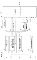
- FIG. 1 is an overall schematic configuration diagram of an electric power steering apparatus according to an embodiment.
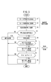
- FIG. 2 is a connection diagram in an ECU in the electric power steering apparatus of FIG. 1 example; It is a flowchart provided for description of a steering angle estimation process and a current fade process.
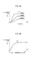
- 4A is an explanatory diagram of a base assist current characteristic referred to in the normal assist process
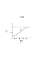
- FIG. 4B is an explanatory diagram of a base assist current characteristic referred to in the abnormal assist process.
- It is explanatory drawing of a current fade characteristic.
- It is explanatory drawing of the continuous steering time reduction characteristic.
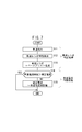
- It is a flowchart provided for description of a vehicle speed ratio correction process and a vehicle speed current limiting process. It is explanatory drawing of a vehicle speed ratio characteristic. It is explanatory drawing of a vehicle speed current limiting characteristic. It is explanatory drawing of an assist electric current correction process.
- FIG. 1 is an overall schematic configuration diagram of an electric power steering apparatus 10 according to this embodiment mounted on a vehicle.
- FIG. 2 is a functional block diagram in the ECU (Electronic Control Unit) 22 in the electric power steering apparatus 10 of FIG.
- the electric power steering apparatus 10 basically steers from the steering wheel 12 (operator operated by the driver to steer the vehicle) to the steered wheels 16 via the steering shaft 14.
- System (steering system) 18 and a torque sensor (torque sensor and steering angle sensor) that is provided on the rotating shaft of the steering system 18 and includes a steering angle sensor 19 therein to detect torque Tr and steering angle ⁇ s of the rotating shaft. 20), an ECU 22 that determines the assist torque Ta based on the output from the torque sensor 20, and the like, and an electric motor (hereinafter also simply referred to as a motor) 24 that is a brushless motor driven by the ECU 22. Deceleration transmission that decelerates the output of the motor 24 and transmits it to the rotating shaft of the steering system 18 as assist torque Ta. It includes a structure 26, a.
- the motor 24 may be a brush motor.
- an input shaft 41 and an output shaft 42 are connected by a torsion bar inside, and two detection coils (not shown) supported by a housing (not shown) are inserted.
- a known configuration is provided so as to surround a cylindrical core (not shown) engaged with the output shafts 41 and 42 (see, for example, Japanese Patent Nos. 3055752 and 2830992).
- the steering angle sensor 19 has a known configuration that detects the rotation angle of the input shaft 41 as the steering angle ⁇ s (for example, see Japanese Patent No. 3055752).
- the torque sensor 20 may have a known configuration using a magnetostrictive film sensor that does not use a torsion bar or a cylindrical core (see, for example, Japanese Patent No. 3964414 or Japanese Patent No. 4057552).
- the torque Tr and steering angle ⁇ s signals output from the torque sensor 20 and the steering angle sensor 19 are supplied to the torque detection circuit 72 of the ECU 22 through the harness 91, and the steering angle ⁇ s is detected as a steering angular velocity. Is supplied to a steering angular velocity calculation unit 74 as a unit.
- the steering shaft 14 includes a main steering shaft 15 integrally coupled to the steering wheel 12, each of which is a rotating shaft, an input shaft 41 coupled to the main steering shaft 15 via a universal joint 46, a rack & The output shaft 42 provided with the pinion 30 of the pinion mechanism 28 is connected.
- the input shaft 41 and the output shaft 42 are supported by bearings 48a, 48b, and 48c, and the pinion 30 is provided at the lower end of the output shaft 42.
- the pinion 30 meshes with the rack teeth 50a of the rack shaft 50 that can reciprocate in the vehicle width direction.
- the steered wheels 16 that are the left and right front wheels are connected to both ends of the rack shaft 50 via tie rods 52.
- the steering system 18 described above includes a rack having the steering wheel 12 to the steering shaft 14 (the main steering shaft 15, the universal joint 46, the input shaft 41, the output shaft 42 provided with the pinion 30), and rack teeth 50a.
- the shaft 50, the tie rod 52, and the steered wheel 16 are included.
- a normal rack and pinion type steering operation can be performed when the steering wheel 12 is steered, and the steered wheels 16 can be steered by operating the steering wheel 12 to change the direction of the vehicle.
- the rack shaft 50, the rack teeth 50a, and the tie rod 52 constitute a steering mechanism.
- the electric power steering apparatus 10 includes the motor 24 that supplies a steering assist force (a steering assist force, also simply referred to as an assist force) for reducing the steering force by the steering wheel 12.
- a steering assist force also simply referred to as an assist force
- the worm gear 54 fixed to the rotating shaft of the motor 24 meshes with a worm wheel gear 56 provided on the lower side of the bearing 48b in the intermediate portion of the output shaft 42.
- the worm gear 54 and the worm wheel gear 56 constitute the speed reduction transmission mechanism 26.
- a rotation angle ⁇ rm (also referred to as a motor mechanical angle) of the rotor 23 of the motor 24 that rotates integrally with the rotation shaft 25 is converted into a rotation angle ⁇ r (motor electric angle) of the rotor 23 by a resolver 58 as a rotor rotation angle detector. And is supplied to the rotor rotation angle detection circuit 76 of the ECU 22 (which functions as a motor mechanical angle calculation circuit for calculating the motor mechanical angle ⁇ rm, as will be described later).
- the resolver 58 is a relative angle detection sensor, but a rotary encoder of an absolute angle detection sensor may be employed instead of the resolver 58. The difference between the rotation angle ⁇ rm (motor mechanical angle) and the rotation angle ⁇ r (motor electrical angle) will be described later.
- the ECU 22 is a computer including a microcomputer, a CPU (Central Processing Unit), a ROM (including EEPROM) and a RAM (Random Access Memory), and other A / D converters, D / A converters, and the like.
- Input / output device, timer as a time measuring means, etc., and the CPU reads out and executes the program recorded in the ROM so that various function realizing parts (function realizing means), for example, a control part, a calculating part, a processing It functions as a part.
- function realizing means for example, a control part, a calculating part, a processing It functions as a part.
- the ECU 22 includes a storage unit 78 as a memory for storing various characteristics (including maps), programs, and the like, which will be described later, and includes the torque detection circuit 72, the steering angular velocity calculation unit (steering angular velocity detection). Part) 74, functions as a rotor rotation angle detection circuit 76, and functions as an abnormality detection part 80, a vehicle stop state detection part 82, a motor control part 84, a time measuring part 85, and the like.
- a storage unit 78 as a memory for storing various characteristics (including maps), programs, and the like, which will be described later, and includes the torque detection circuit 72, the steering angular velocity calculation unit (steering angular velocity detection). Part) 74, functions as a rotor rotation angle detection circuit 76, and functions as an abnormality detection part 80, a vehicle stop state detection part 82, a motor control part 84, a time measuring part 85, and the like.
- the torque detection circuit 72 is a signal corresponding to the torque Tr from the differential signal of the signal related to the torque Tr output from the two detection coils (not shown) of the torque sensor 20 through the harness 91 (for convenience of understanding, Torque Tr) is generated and supplied to the motor control unit 84.
- the rotor rotation angle detection circuit 76 calculates (detects) a rotation angle (motor mechanical angle) ⁇ rm corresponding to the rotation of the rotor 23 of the motor 24 from the rotation angle ⁇ r (motor electrical angle) supplied from the resolver 58. While supplying to the motor control part 84, it supplies to the steering angular velocity calculation part 74.
- FIG. 1 The rotor rotation angle detection circuit 76 calculates (detects) a rotation angle (motor mechanical angle) ⁇ rm corresponding to the rotation of the rotor 23 of the motor 24 from the rotation angle ⁇ r (motor electrical angle) supplied from the resolver 58. While supplying to the motor control part 84, it supplies to the steering angular velocity calculation part 74.
- the steering angular velocity calculation unit 74 when a steering angle (also referred to as a steering angle, steering angle, or steering angle of the steering shaft 14) ⁇ s is supplied from the steering angle sensor 19 that is operating normally, the steering angle sensor.
- the steering angular velocity calculation unit 74 is calculated by the rotor rotation angle detection circuit 76 based on the rotation angle ⁇ r of the resolver 58.
- the abnormality detection unit 80 monitors the torque Tr, which is the output of the torque detection circuit 72, and the steering angle ⁇ s, which is the output of the steering angle sensor 19, so that the fusing failure between the terminal of the torque sensor 20 and the harness 91, Opening of the harness 91 (disconnection of the harness 91) or short-circuit between the harnesses 91, abnormality of the differential amplifier in the torque detection circuit 72, for example, the output is fixed at 0 volts or a voltage other than 0 to 5 volts Is detected, the abnormality detection signal Sab is supplied to the motor control unit 84 and the steering angular velocity calculation unit 74.
- the output of the vehicle speed sensor 86 for detecting the vehicle speed Vs from the number of rotations of the front and rear wheels or the transmission, that is, the vehicle speed Vs, is supplied to the motor control unit 84 and the vehicle stop state detection unit 82 of the ECU 22 through the harness 94.
- the brake operation signal Sb of the parking brake 88 is supplied through the harness 95 to the vehicle stop state detection unit 82 and the motor control unit 84 of the ECU 22.
- signals such as the vehicle speed Vs and the brake operation signal Sb are supplied to the ECU 22 through an in-vehicle network such as CAN (controller area network).
- CAN controller area network
- You may connect by what is called a point-to-point wiring system instead of an in-vehicle network.
- the vehicle stop state detection unit 82 supplies the vehicle stop detection signal Sstop to the motor control unit 84. To do.
- the motor control unit 84 determines the assist current Ia of the motor 24 corresponding to the assist torque Ta, in addition to the torque Tr and the steering angular velocity ⁇ s ′, the rotation angle (motor mechanical angle) ⁇ rm of the rotor 23 and the estimated steering angle ⁇ sc. Based on the estimated steering angular velocity ⁇ sc ′, the abnormality detection signal Sab, the vehicle speed Vs, the brake operation signal Sb, and the like, a characteristic (described later) stored in the storage unit 78 (characteristic storage unit) is referred to, and the program is executed. The assist current Ia thus determined is supplied to the stator coil of each phase of the motor 24 through the harness 93.
- the motor 24 generates an assist torque Ta corresponding to the supplied assist current Ia and applies it to the output shaft 42 through the deceleration transmission mechanism 26 to generate a steering assist force on the steering shaft 14.
- FIG. 3 is a flowchart for explaining the operation of the first and second embodiments. The process according to this flowchart is repeatedly executed every predetermined time.
- the ECU 22 performs a steering angle estimation process (estimated steering angle calculation process) in steps S1 to S3 regardless of whether the torque sensor 20 or the steering angle sensor 19 is abnormal or normal.
- step S1 the rotor rotation angle detection circuit 76 integrates the rotation angle ⁇ r (electric angle of the rotor 23) detected by the resolver 58, and calculates the motor electric angle ⁇ re.
- step S2 the rotor rotation angle detection circuit 76 multiplies the calculated motor electrical angle ⁇ re by the number of pole pairs of the resolver 58 as shown in the following equation (1) to obtain the rotor 23 (rotation shaft 25). ) Is calculated (converted to the motor mechanical angle ⁇ rm) and supplied to the motor control unit 84 and the steering angular velocity calculation unit 74.
- step S3 the motor control unit 84 and / or the rotor rotation angle detection circuit 76 uses the calculated motor mechanical angle ⁇ rm as the steering angle (estimated steering) of the steering shaft 14 as shown in the following equation (2).
- ⁇ sc ⁇ rm ⁇ reduction ratio of deceleration transmission mechanism 26 (2 )
- the motor rotation speed N and the estimated steering rotation speed Nsc are calculated by the motor control unit 84.
- the steering wheel 12 is rotated to the right and cut, and then turned to the left and turned back to return to the straight traveling state. Therefore, basically, when turning right from the straight traveling state and returning to the straight traveling state, the right rotation is the cutting direction and the left rotation is the returning direction.
- the steering angle ⁇ s (estimated steering angle ⁇ sc) when the steering wheel 12 is rotated rightward from the straight traveling state (neutral state of the steering wheel 12) becomes a positive value, and the straight traveling state (the steering wheel 12 of the steering wheel 12).
- the steering angle ⁇ s (estimated steering angle ⁇ sc) when the steering wheel 12 is rotated in the left direction from the neutral state is a negative value.
- the magnitude of the angle if there is a positive / negative sign, it is complicated. Therefore, in the following description, unless otherwise noted, a case where the vehicle turns right from the straight traveling state and returns to the straight traveling state will be described as an example (on the coordinates of the steering assist characteristic, the first quadrant). In this case, both the steering angle ⁇ s and the estimated steering angle ⁇ sc take positive values.
- the rotor rotation angle detection circuit 76 based on the rotation angle ⁇ r detected by the resolver 58, The estimated steering angle ⁇ sc [deg] and the estimated steering angular velocity ⁇ sc ′ [deg / s] from which the steering angle ⁇ s [deg] is estimated by the steering angular velocity calculation unit 74 and the motor control unit 84 can be obtained.
- the steering assist force applied to the steering wheel 12 by rotating the motor 24 is basically applied in the direction in which the steering angle ⁇ s or the estimated steering angle ⁇ sc is changing.
- step S4 it is detected whether or not the abnormality detection signal Sab is supplied from the abnormality detection unit 80.
- step S4 when the motor control unit 84 detects the abnormality detection signal Sab related to the torque sensor 20 and the steering angle sensor 19, the motor control unit 84 executes the processing after step S5.
- the motor control unit 84 executes the processing after step S5.
- the torque sensor 20 with a built-in steering angle sensor 19 shown in FIG. 1 the supply of power is stopped by opening or shorting the harness 91, and the outputs of the steering angle sensor 19 and the torque sensor 20 are in an abnormal state at the same time. There are many cases.
- step S4 when the motor control unit 84 does not detect the abnormality detection signal Sab, normal processing (normal assist processing) is performed in step S10. In this normal process, since the torque sensor 20 and the steering angle sensor 19 are normal, a conventional steering assist force application operation is performed.
- the motor control unit 84 has characteristics (base assist current characteristics) of the base assist current Ia [A] with respect to the steering torque Tr [kgfcm] with the vehicle speed Vs as a parameter shown in FIG. Alternatively, it is also referred to as a base assist characteristic.) 101 is referred (searched), and basically the base assist current Ia that increases as the vehicle speed decreases is calculated to drive the motor 24.
- step S4 when the motor control unit 84 detects the abnormality detection signal Sab indicating that the torque sensor 20 or the like has become abnormal, the abnormality assist process in step S5 is executed.
- step S5 the motor control unit 84 has characteristics (referred to as base assist current characteristics or base assist characteristics) 102 of the base assist current Ia [A] with respect to the estimated steering angle ⁇ sc shown in FIG. Referring to (searching), the base assist current Ia is calculated, and the motor 24 is driven based on the calculated base assist current Ia.
- base assist current characteristics or base assist characteristics characteristics
- the base assist current characteristic 102 may be stored in the storage unit 78 as a map, or may be stored in the storage unit 78 using a calculation formula. In the case where the map is stored discretely in the storage unit 78, it is preferable to obtain the value between them by interpolation.
- the estimated steering angle ⁇ sc [deg] is a value from 0 [deg] to a dead zone corresponding steering angle ⁇ d [deg] (about 0 to 10 [deg]). In this embodiment, it is set to 10 [deg].)
- Ia 0 [A] is set (a region where the assist current Ia does not flow), and the dead zone corresponding steering angle ⁇ d [ deg] or higher, and the estimated steering angle ⁇ sc is increased in accordance with the increase of the estimated steering angle ⁇ sc (increased approximately proportionally).
- the characteristic is set to take a constant value (the value of the base assist current Ia is saturated).
- the processing from steps S1 to S5 described above corresponds to the processing in the first embodiment.
- the electric power steering apparatus 10 applies assist torque to a torque sensor 20 as a torque detection unit that detects torque Tr generated in the steering system 18 and an output shaft 42 that is a rotating shaft of the steering system 18.
- the motor 24 is driven based on the motor 24 to be applied, the resolver 58 as a rotor rotation angle detection unit for detecting the rotation angle ⁇ r of the rotor 23 of the motor 24, and the torque Tr detected by the torque sensor 20.
- An electric power steering apparatus 10 including a motor control unit 84 that controls current (step S10), and includes an abnormality detection unit 80 that detects whether an abnormality has occurred in the torque sensor 20 or the torque detection circuit 72, When the abnormality detection unit 80 detects an abnormality in the torque sensor 20 or the torque detection circuit 72, the motor control unit 84 An estimated steering angle ⁇ sc is calculated based on the motor electrical angle ⁇ re that is an integrated value of the rotation angle ⁇ r detected by the Luba 58, and the characteristic 102 of the base assist current Ia [A] with respect to the estimated steering angle ⁇ sc is referred to. The base assist current Ia is calculated and controlled to drive the motor 24.
- a predetermined steering assist control for applying a steering assist force by the motor 24 to the steering wheel 12 by passing an assist current Ia based on the assist current characteristic 102 is performed.
- the steering assist control at the time of abnormality is a provisional assist process, and various restrictions are imposed as described later.
- a neutral point (neutral state) correction process for updating the memory with the estimated steering angle ⁇ sc corresponding to the rotation angle ⁇ r that is the output of the resolver 58 as a zero value (0 [deg]) is appropriately performed.
- the provision of the steering assist force using the rotor rotation angle detection circuit 76 is a provisional process
- the abnormality detection unit 80 detects an abnormality in the torque sensor 20 or the like, it is The operator (driver) is informed that the steering assist process corresponding to the abnormality is being performed. Thereby, the operator (driver) can drive the vehicle to a safe place by using the assist force by the provisional electric power steering using the rotation angle ⁇ r of the rotor 23 of the motor 24.
- the assist force by the provisional electric power steering imposes various restrictions on the normal assist process in step S21 in which the torque sensor 20 and the like are in a normal state.
- FIG. 5 shows a cut-in current fade characteristic (also referred to as a cut-in current fade characteristic) 103 used for a current fade process stored in the storage unit 78, and a switch-back current fade characteristic (also referred to as a switch-back current fade characteristic). .)
- the example 104 is shown, and a part of the base assist current characteristic 102 of FIG. 4B is shown again.
- the characteristics of the first quadrant in FIG. 5 (the cutting direction in the right direction from 0 [deg] on the horizontal axis toward the large value in the positive direction, and the positive direction) (Characteristics related to the return direction toward a small value in the 0 [deg] direction).
- step S6 it is determined from the estimated steering angular velocity ⁇ sc ′, which is a differential value of the estimated steering angle ⁇ sc, whether the assist current Ia is being applied and the steering wheel 12 is being turned.
- the estimated steering angular velocity ⁇ sc ′ is calculated by the steering angular velocity calculator 74 or the motor controller 84.
- the reason why the cutting current fade characteristic 103 indicated by the one-dot chain line has a smaller assist amount (assist current Ia) than the base assist current characteristic 102 indicated by the solid line is that This is to prevent overshoot.
- the motor control unit 84 refers to the time from the start of turning ⁇ the continuous steering time tr (in the same direction).
- ⁇ Is measured by the timer 85 and the ratio (referred to as a continuous steering reduction ratio or a continuous steering reduction ratio) Rc ⁇ Rc is 1 (no reduction) to 0 with reference to the continuous steering time reduction characteristic 105 shown in FIG.
- the values up to (assum the assist current Ia to zero) are taken.
- the assist current Ia calculated by the estimated steering angle ⁇ sc on the base assist current characteristic 102 is multiplied by the continuous steering reduction ratio Rc corresponding to the continuous steering time tr, and then As shown in the equation (3), the assist current Ia is faded (reduced).
- Ia on the right side of the equation means base assist current on the base assist current characteristic 102
- Ia on the left side means faded (reduced) base assist current on the cut-in current fade characteristic 103.
- the continuous steering reduction ratio Rc of the continuous steering time reduction characteristic 105 is such that the assist current Ia is reduced by 10% in 1 second (1 [s]).
- the assist current Ia is set to zero.
- the assist current fade characteristic 103 that assists less than the base assist current characteristic 102 (assist current Ia) is assisted. Like to do.
- the assist current Ia is limited to the allowable maximum assist current Iamax ⁇ coordinate point 106 in FIG. (See ⁇ scth, Iamax) ⁇ .
- the switchback current fade in step S9 is performed in order to promote the return of the steering wheel 12 at the time of switchback. Execute the process.
- the assist current Ia is determined along the switchback current fade characteristic 104 of FIG.
- the estimated steering angle ⁇ sc is switched back leftward because the steering wheel 12 (steering system 12) acting on the traveling vehicle is moved in the straight direction (neutral position). It depends on the force to return, so-called SAT (Self Aligning Torque).
- the steering angular velocity calculation unit 74 or the motor control unit 84 that calculates the estimated angular velocity ⁇ sc ′ of the output shaft 42 that is the rotation axis of the steering system 18 is further provided.
- the assist current Ia for driving the motor 24 is switched back, and the current fade characteristic 104 ⁇ the gradient of this characteristic 104 is the load (front axle load of the vehicle) for each individual vehicle, the vehicle speed Vs, the road surface condition It changes according to etc. ⁇ ,
- the over assist current can be prevented.
- the steering angle sensor 19 attached to the torque sensor 20 or the steering angle sensor provided independently of the torque sensor 20 is in a normal state, the steering angle ⁇ s that is the output of the steering angle sensor 19 or the like. Is differentiated to calculate the steering angular velocity ⁇ s ′ and the current fade process can be performed.
- the assist current needs to be increased in the medium and high speed regions as compared to the low speed region.
- FIG. 8 shows a vehicle speed ratio characteristic 109 stored in the storage unit 78 for correcting the base assist current characteristic 102 in accordance with the vehicle speed Vs.
- the ratio R is increased proportionally.
- the ratio R is fixed to ⁇ 1.
- Vs 10 [km / h] or less
- R ⁇ 0.2 is set.
- the assist current Ias after the vehicle speed correction can be obtained by the following equation (4).
- the assist current needs to be increased in the medium speed and high speed areas as compared with the low speed area, but the steering angle range is narrowed as the vehicle speed Vs increases, the viewpoint of preventing overcurrent, and the resolver 58.
- a current limit value Imax that is the maximum value (limit value) of the assist current for each vehicle speed Vs.
- the first constant value Imax1 is set to 10 to 30 [km / h].
- h] is gradually increased, about 30 to 60 [km / h] is set to a second constant value Imax2, gradually decreased to about 60 to 120 [km / h], and gradually increased to about 120 [km] or more. It was found that setting the third constant value Imax3 to be practically preferable (Imax3 ⁇ Imax1 ⁇ Imax2).
- step S5 the base assist current Ia correction process (third embodiment) according to the flowchart shown in FIG. 7 is performed.
- the vehicle speed ratio characteristic 109 shown in FIG. 8 is retrieved (referenced) in step S12, and as shown in the equation (4), the vehicle speed ratio characteristic 109 shown in FIG.
- the base assist current Ia is multiplied by the ratio R to calculate the assist current Ias after the vehicle speed correction.
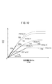
- characteristics 110, 150, 180, and 220 indicated by solid lines indicate vehicle speeds Vs of 10 [km / h], 50 [km / h], 80 [km / h], and 120 [ km / h] shows the characteristic of the assist current Ias after the vehicle speed correction.
- the motor control unit 84 detects abnormality.
- a storage unit 78 is obtained from the estimated steering angle ⁇ sc calculated based on the rotation angle ⁇ r of the rotor 23 detected by the resolver 58 as the rotor rotation angle detection unit.
- the base assist current Ia for driving the motor 24 is obtained by referring to the characteristic 102 stored in the vehicle, and the base assist current Ia is detected by the vehicle speed sensor 86.
- the steering assist force is applied to the entire vehicle speed range by the steering assist force required.
- step S14 the value of the assist current Ias after vehicle speed correction obtained in step S13 is the current limit value Imax (Imax1, Imax2, determined by the vehicle speed current limit characteristic 108 shown in FIG. 9 at the vehicle speed Vs. It is determined whether or not the value exceeds Imax3). If Ias> Imax, the assist current Ias is limited to the current limit value Imax corresponding to the vehicle speed Vs in step S15. When Ias ⁇ Imax, the assist current Ias is used as it is.
- characteristics 110, 150, 180, and 220 indicated by solid lines are currents taking the ratio R into consideration, and characteristics 110a, 150a, 180a, and 220a indicated by dotted lines are characteristics taking into account the current limit value Imax.
- the storage unit 78 that stores the current limit value Imax corresponding to the vehicle speed Vs as the characteristic 108, an excessive output can be suppressed, and the ratio R shown in FIG. It is possible to obtain a characteristic that cannot be set only by vehicle speed interlocking control based on.
- the vehicle stop state detection unit 82 detects the motor control unit 84. Is supplied with a vehicle stop detection signal Sstop. At this time, the motor control unit 84 can prevent the steering assist force from being unnecessarily applied by setting the assist current Ia to a zero value.
- the torque sensor 20 fails and the torque sensor 20 cannot detect the steering torque Tr, it is detected by the resolver 58 of the motor 24 or the like.
- the steering angle ⁇ s is estimated using the rotation angle ⁇ r of the rotor 23, the steering angular velocity ⁇ s ′ is estimated, and a predetermined steering assist by the motor 24 is performed using the estimated steering angle ⁇ sc and / or the estimated steering angular velocity ⁇ sc ′. Power can be granted.
Priority Applications (4)
| Application Number | Priority Date | Filing Date | Title |
|---|---|---|---|
| CN201180009482.1A CN102762435B (zh) | 2010-02-25 | 2011-01-27 | 电动动力转向装置 |
| DE112011100682.9T DE112011100682B4 (de) | 2010-02-25 | 2011-01-27 | Elektrische Servolenkungsvorrichtung |
| JP2012501711A JP5635071B2 (ja) | 2010-02-25 | 2011-01-27 | 電動パワーステアリング装置 |
| US13/579,106 US8960363B2 (en) | 2010-02-25 | 2011-01-27 | Electric power steering device |
Applications Claiming Priority (2)
| Application Number | Priority Date | Filing Date | Title |
|---|---|---|---|
| JP2010040583 | 2010-02-25 | ||
| JP2010-040583 | 2010-02-25 |
Publications (1)
| Publication Number | Publication Date |
|---|---|
| WO2011105154A1 true WO2011105154A1 (ja) | 2011-09-01 |
Family
ID=44506575
Family Applications (1)
| Application Number | Title | Priority Date | Filing Date |
|---|---|---|---|
| PCT/JP2011/051570 WO2011105154A1 (ja) | 2010-02-25 | 2011-01-27 | 電動パワーステアリング装置 |
Country Status (5)
| Country | Link |
|---|---|
| US (1) | US8960363B2 (de) |
| JP (1) | JP5635071B2 (de) |
| CN (1) | CN102762435B (de) |
| DE (1) | DE112011100682B4 (de) |
| WO (1) | WO2011105154A1 (de) |
Cited By (6)
| Publication number | Priority date | Publication date | Assignee | Title |
|---|---|---|---|---|
| JP2014122015A (ja) * | 2012-12-21 | 2014-07-03 | Hyundai Motor Company Co Ltd | ハイブリッド車両用操向装置及びその制御方法 |
| JP2014208511A (ja) * | 2013-03-25 | 2014-11-06 | 株式会社ジェイテクト | 車両用操舵装置 |
| JP2014234146A (ja) * | 2013-06-05 | 2014-12-15 | オムロンオートモーティブエレクトロニクス株式会社 | 電動パワーステアリング制御装置 |
| KR20160041350A (ko) * | 2014-10-07 | 2016-04-18 | 현대모비스 주식회사 | 페일세이프 기능을 갖는 전동식 동력 조향장치 및 그 제어방법 |
| US9828023B2 (en) | 2015-03-31 | 2017-11-28 | Honda Motor Co., Ltd. | Electric power steering device |
| US20230040044A1 (en) * | 2020-04-20 | 2023-02-09 | Thyssenkrupp Presta Ag | Degradation concept for a steer-by-wire steering system |
Families Citing this family (23)
| Publication number | Priority date | Publication date | Assignee | Title |
|---|---|---|---|---|
| JP5171487B2 (ja) * | 2008-09-02 | 2013-03-27 | 本田技研工業株式会社 | ステアリング装置 |
| EP2662266B1 (de) * | 2011-01-07 | 2015-11-25 | Honda Motor Co., Ltd. | Elektrische servolenkvorrichtung |
| EP2799310B1 (de) * | 2013-04-30 | 2016-06-08 | Steering Solutions IP Holding Corporation | Bereitstellung von Unterstützungsdrehmoment ohne Handraddrehmomentsensor |
| JP6078444B2 (ja) * | 2013-09-20 | 2017-02-08 | 日立オートモティブシステムズ株式会社 | パワーステアリング装置および車両搭載機器の制御装置 |
| JP2015160504A (ja) * | 2014-02-27 | 2015-09-07 | 株式会社ジェイテクト | 車両用操舵装置、当該装置の故障判定方法、及び転舵モータの制御方法 |
| JP5967339B2 (ja) * | 2014-06-25 | 2016-08-10 | 日本精工株式会社 | 電動パワーステアリング装置 |
| JP6040963B2 (ja) * | 2014-07-07 | 2016-12-07 | 株式会社デンソー | 回転機の制御装置 |
| WO2016019344A1 (en) * | 2014-07-31 | 2016-02-04 | Trw Automotive U.S. Llc | Assist compensation for actively controlled power steering systems |
| US10144445B2 (en) | 2014-09-15 | 2018-12-04 | Steering Solutions Ip Holding Corporation | Modified static tire model for providing assist without a torque sensor for zero to low vehicle speeds |
| JP6379907B2 (ja) * | 2014-09-16 | 2018-08-29 | 株式会社ジェイテクト | 電動パワーステアリング装置 |
| KR101639479B1 (ko) * | 2014-10-13 | 2016-07-13 | 주식회사 만도 | 전동식 조향 제어 방법 및 그 장치 |
| JP5965968B2 (ja) * | 2014-11-19 | 2016-08-10 | 本田技研工業株式会社 | 電動パワーステアリング装置及び保舵支援制御装置 |
| CN107257760B (zh) * | 2014-12-22 | 2019-06-18 | Trw有限公司 | 电力辅助转向系统 |
| US10464594B2 (en) | 2015-09-03 | 2019-11-05 | Steering Solutions Ip Holding Corporation | Model based driver torque estimation |
| US10336363B2 (en) | 2015-09-03 | 2019-07-02 | Steering Solutions Ip Holding Corporation | Disabling controlled velocity return based on torque gradient and desired velocity error |
| TWI579179B (zh) * | 2015-12-30 | 2017-04-21 | 上銀科技股份有限公司 | 檢測方向盤轉角傳感器故障之系統及其方法 |
| US10308278B2 (en) * | 2016-03-25 | 2019-06-04 | Nsk Ltd. | Electric power steering apparatus |
| US10155534B2 (en) | 2016-06-14 | 2018-12-18 | Steering Solutions Ip Holding Corporation | Driver intent estimation without using torque sensor signal |
| JP6399260B2 (ja) * | 2016-07-05 | 2018-10-03 | 日本精工株式会社 | 電動パワーステアリング装置 |
| KR20190028842A (ko) * | 2017-09-11 | 2019-03-20 | 주식회사 만도 | 페일-세이프 전동식 파워 스티어링 장치 및 방법 |
| KR102024550B1 (ko) * | 2017-10-16 | 2019-09-24 | 주식회사 만도 | 전동식 동력 조향 시스템의 페일 세이프 제어장치 및 제어방법 |
| DE102019206980B4 (de) * | 2019-05-14 | 2023-06-22 | Volkswagen Aktiengesellschaft | Verfahren und Lenkungssteuergerät zum Ermitteln einer Stellgröße für das Einstellen eines Servolenkmoments bei einem Fahrzeuglenksystem |
| CN113479257A (zh) * | 2021-08-23 | 2021-10-08 | 浙江吉利控股集团有限公司 | 一种转向操纵系统及车辆 |
Citations (5)
| Publication number | Priority date | Publication date | Assignee | Title |
|---|---|---|---|---|
| JPH11129925A (ja) * | 1997-10-31 | 1999-05-18 | Nissan Motor Co Ltd | 電動式パワーステアリング装置 |
| JP2001106099A (ja) * | 1999-10-14 | 2001-04-17 | Koyo Seiko Co Ltd | 電動パワーステアリング装置 |
| JP2002225745A (ja) * | 2001-02-02 | 2002-08-14 | Nsk Ltd | 電動パワーステアリング装置の制御装置 |
| JP2003072580A (ja) * | 2001-09-07 | 2003-03-12 | Koyo Seiko Co Ltd | 電動パワーステアリング装置 |
| JP2005067262A (ja) * | 2003-08-28 | 2005-03-17 | Nissan Motor Co Ltd | 電動パワーステアリング制御装置 |
Family Cites Families (20)
| Publication number | Priority date | Publication date | Assignee | Title |
|---|---|---|---|---|
| JPH0696389B2 (ja) * | 1986-10-29 | 1994-11-30 | 株式会社日立製作所 | 電動式パワ−ステアリング制御装置 |
| JPH0355752A (ja) | 1989-07-25 | 1991-03-11 | Hikari Gijutsu Kenkyu Kaihatsu Kk | 走査トンネル顕微鏡 |
| JPH03235759A (ja) * | 1990-02-09 | 1991-10-21 | Mazda Motor Corp | 電動式パワーステアリング装置 |
| JPH0457552A (ja) | 1990-06-27 | 1992-02-25 | Mitsubishi Electric Corp | 自動車電話機 |
| JP3214917B2 (ja) | 1992-09-14 | 2001-10-02 | マツダ株式会社 | 自動車の音声による経路誘導装置 |
| US5712563A (en) | 1994-06-13 | 1998-01-27 | Honda Giken Kogyo Kabushiki Kaisha | Steering torque sensor utilizing a displacement detector having a pulse power supply |
| JP3055752B2 (ja) | 1994-06-13 | 2000-06-26 | 本田技研工業株式会社 | 操舵トルクセンサ |
| JP2830992B2 (ja) | 1995-09-01 | 1998-12-02 | 本田技研工業株式会社 | 電動パワーステアリング装置 |
| US6943512B2 (en) * | 2002-02-04 | 2005-09-13 | Nsk Ltd. | Control apparatus for electric power steering system |
| EP1666339B1 (de) * | 2003-08-28 | 2018-12-05 | NSK Ltd. | Steuerung für elektrische servolenkungsvorrichtungen |
| JP4057552B2 (ja) | 2004-05-10 | 2008-03-05 | 本田技研工業株式会社 | トルクセンサとそのトルクセンサを用いた電動パワーステアリング装置 |
| US7506554B2 (en) | 2004-08-25 | 2009-03-24 | Honda Motor Co., Ltd. | Magnetostrictive torque sensor system and electric steering system |
| JP3964414B2 (ja) | 2004-08-25 | 2007-08-22 | 本田技研工業株式会社 | 磁歪式トルクセンサと電動ステアリング装置 |
| JP2006143151A (ja) * | 2004-11-24 | 2006-06-08 | Honda Motor Co Ltd | 電動パワーステアリング装置 |
| JP2007283891A (ja) * | 2006-04-17 | 2007-11-01 | Jtekt Corp | 車両用操舵装置 |
| JP5273929B2 (ja) * | 2007-03-06 | 2013-08-28 | 株式会社ジェイテクト | 電動パワーステアリング装置 |
| JP2009269540A (ja) | 2008-05-09 | 2009-11-19 | Jtekt Corp | 電動パワーステアリング装置 |
| DE102008032081A1 (de) | 2008-07-08 | 2010-01-14 | Volkswagen Ag | Verfahren und System zum Betreiben einer elektromechnischen Lenkung eines Fahrzeugs |
| JP5229645B2 (ja) * | 2010-06-24 | 2013-07-03 | 株式会社デンソー | 電動機駆動装置、および、これを用いた電動パワーステアリング装置 |
| EP3144845B1 (de) | 2014-06-30 | 2019-04-03 | Nippon Telegraph and Telephone Corporation | Detektionsvorrichtung, detektionsverfahren und detektionsprogramm |
-
2011
- 2011-01-27 DE DE112011100682.9T patent/DE112011100682B4/de not_active Expired - Fee Related
- 2011-01-27 JP JP2012501711A patent/JP5635071B2/ja active Active
- 2011-01-27 US US13/579,106 patent/US8960363B2/en active Active
- 2011-01-27 WO PCT/JP2011/051570 patent/WO2011105154A1/ja active Application Filing
- 2011-01-27 CN CN201180009482.1A patent/CN102762435B/zh active Active
Patent Citations (5)
| Publication number | Priority date | Publication date | Assignee | Title |
|---|---|---|---|---|
| JPH11129925A (ja) * | 1997-10-31 | 1999-05-18 | Nissan Motor Co Ltd | 電動式パワーステアリング装置 |
| JP2001106099A (ja) * | 1999-10-14 | 2001-04-17 | Koyo Seiko Co Ltd | 電動パワーステアリング装置 |
| JP2002225745A (ja) * | 2001-02-02 | 2002-08-14 | Nsk Ltd | 電動パワーステアリング装置の制御装置 |
| JP2003072580A (ja) * | 2001-09-07 | 2003-03-12 | Koyo Seiko Co Ltd | 電動パワーステアリング装置 |
| JP2005067262A (ja) * | 2003-08-28 | 2005-03-17 | Nissan Motor Co Ltd | 電動パワーステアリング制御装置 |
Cited By (7)
| Publication number | Priority date | Publication date | Assignee | Title |
|---|---|---|---|---|
| JP2014122015A (ja) * | 2012-12-21 | 2014-07-03 | Hyundai Motor Company Co Ltd | ハイブリッド車両用操向装置及びその制御方法 |
| JP2014208511A (ja) * | 2013-03-25 | 2014-11-06 | 株式会社ジェイテクト | 車両用操舵装置 |
| JP2014234146A (ja) * | 2013-06-05 | 2014-12-15 | オムロンオートモーティブエレクトロニクス株式会社 | 電動パワーステアリング制御装置 |
| KR20160041350A (ko) * | 2014-10-07 | 2016-04-18 | 현대모비스 주식회사 | 페일세이프 기능을 갖는 전동식 동력 조향장치 및 그 제어방법 |
| KR102172089B1 (ko) | 2014-10-07 | 2020-10-30 | 현대모비스 주식회사 | 페일세이프 기능을 갖는 전동식 동력 조향장치 및 그 제어방법 |
| US9828023B2 (en) | 2015-03-31 | 2017-11-28 | Honda Motor Co., Ltd. | Electric power steering device |
| US20230040044A1 (en) * | 2020-04-20 | 2023-02-09 | Thyssenkrupp Presta Ag | Degradation concept for a steer-by-wire steering system |
Also Published As
| Publication number | Publication date |
|---|---|
| CN102762435B (zh) | 2015-09-30 |
| DE112011100682T5 (de) | 2013-03-07 |
| JPWO2011105154A1 (ja) | 2013-06-20 |
| CN102762435A (zh) | 2012-10-31 |
| US8960363B2 (en) | 2015-02-24 |
| US20120312627A1 (en) | 2012-12-13 |
| DE112011100682B4 (de) | 2018-05-09 |
| JP5635071B2 (ja) | 2014-12-03 |
Similar Documents
| Publication | Publication Date | Title |
|---|---|---|
| JP5635071B2 (ja) | 電動パワーステアリング装置 | |
| US9266559B2 (en) | Electric power steering device | |
| US10272941B2 (en) | Vehicle steering device | |
| US7406375B2 (en) | Electric power steering apparatus and method for controlling the electric power steering apparatus | |
| US7628247B2 (en) | Electric power steering device equipped with automatic steering function | |
| US10293856B2 (en) | Vehicular steering system | |
| EP2599687B1 (de) | Fahrzeuglenkungssystem | |
| JP2013107450A (ja) | 四輪操舵制御装置 | |
| JP7234968B2 (ja) | 転舵装置 | |
| JP2013116685A (ja) | 車両用操舵装置 | |
| JP5416722B2 (ja) | 電動パワーステアリング装置 | |
| JP2014004920A (ja) | 車両の電動パワーステアリング装置 | |
| JPWO2020003506A1 (ja) | 操舵装置 | |
| JP2004338562A (ja) | 電動パワーステアリング制御装置 | |
| JP6098352B2 (ja) | 車両用操舵制御装置及び車両用操舵制御方法 | |
| EP2597015B1 (de) | Hydraulisches Servolenksystem | |
| JP2010202062A (ja) | 電動パワーステアリング装置 | |
| JP5427796B2 (ja) | 電動パワーステアリング装置 | |
| JP5427797B2 (ja) | 電動パワーステアリング装置 | |
| US20200130736A1 (en) | Steering control device | |
| JP2013023002A (ja) | 電動パワーステアリング装置 | |
| JP2008062686A (ja) | 電動パワーステアリング制御装置及びその制御方法 | |
| JP6098351B2 (ja) | 車両用操舵制御装置及び車両用操舵制御方法 | |
| JP6180959B2 (ja) | 電動パワーステアリング装置、レゾルバ故障検出装置、レゾルバ故障検出方法 | |
| JP2016002884A (ja) | ステアリング装置 |
Legal Events
| Date | Code | Title | Description |
|---|---|---|---|
| WWE | Wipo information: entry into national phase |
Ref document number: 201180009482.1 Country of ref document: CN |
|
| 121 | Ep: the epo has been informed by wipo that ep was designated in this application |
Ref document number: 11747118 Country of ref document: EP Kind code of ref document: A1 |
|
| WWE | Wipo information: entry into national phase |
Ref document number: 2012501711 Country of ref document: JP |
|
| WWE | Wipo information: entry into national phase |
Ref document number: 13579106 Country of ref document: US |
|
| WWE | Wipo information: entry into national phase |
Ref document number: 1120111006829 Country of ref document: DE Ref document number: 112011100682 Country of ref document: DE |
|
| 122 | Ep: pct application non-entry in european phase |
Ref document number: 11747118 Country of ref document: EP Kind code of ref document: A1 |