WO2011102490A1 - マスク - Google Patents
マスク Download PDFInfo
- Publication number
- WO2011102490A1 WO2011102490A1 PCT/JP2011/053573 JP2011053573W WO2011102490A1 WO 2011102490 A1 WO2011102490 A1 WO 2011102490A1 JP 2011053573 W JP2011053573 W JP 2011053573W WO 2011102490 A1 WO2011102490 A1 WO 2011102490A1
- Authority
- WO
- WIPO (PCT)
- Prior art keywords
- base
- joint
- mask
- end side
- ear hook
- Prior art date
Links
Images

Classifications
-
- A—HUMAN NECESSITIES
- A41—WEARING APPAREL
- A41D—OUTERWEAR; PROTECTIVE GARMENTS; ACCESSORIES
- A41D13/00—Professional, industrial or sporting protective garments, e.g. surgeons' gowns or garments protecting against blows or punches
- A41D13/05—Professional, industrial or sporting protective garments, e.g. surgeons' gowns or garments protecting against blows or punches protecting only a particular body part
- A41D13/11—Protective face masks, e.g. for surgical use, or for use in foul atmospheres
- A41D13/1107—Protective face masks, e.g. for surgical use, or for use in foul atmospheres characterised by their shape
- A41D13/1115—Protective face masks, e.g. for surgical use, or for use in foul atmospheres characterised by their shape with a horizontal pleated pocket
-
- A—HUMAN NECESSITIES
- A62—LIFE-SAVING; FIRE-FIGHTING
- A62B—DEVICES, APPARATUS OR METHODS FOR LIFE-SAVING
- A62B23/00—Filters for breathing-protection purposes
- A62B23/02—Filters for breathing-protection purposes for respirators
- A62B23/025—Filters for breathing-protection purposes for respirators the filter having substantially the shape of a mask
Definitions
- This invention relates to the construction technique of the mask which covers a wearer's mouth, nose, etc.
- JP-A-3-34195 discloses a mask covering a wearer's mouth and nose.
- the mask includes a mask main body that covers the mouth, a left ear hook, and a right ear hook.
- the left ear hook and the right ear hook are heat welded to the mask main body.
- the joint part that joins the mask main body part, the left ear hook part, and the right ear hook part is exposed on the wearing surface (the wearer side face) of the mask main body part. For this reason, there exists a possibility that a hard junction part may contact a wearer's skin.
- the present invention was devised in view of such points, and an object thereof is to provide a technique effective in preventing the joint portion of the mask from coming into contact with the wearer's skin.
- the mask of the present invention may be a disposable mask intended for one-time use or several-time use, or a mask that can be used repeatedly by washing or the like.
- One aspect of the invention includes at least a mask body and first and second ear hooks.
- the mask main body is a member that covers the mouth and nose of the wearer, and the first and second ear hooks are members that are hung on the wearer's left and right ears.
- the first and second ear hooks are joined to the mask main body by first and second joints that are separated from each other in the first direction.
- a 1st ear hook part is hung on a wearer's left ear
- a 2nd ear hook part is hung on a wearer's right ear.
- the “first direction” represents the longitudinal direction (width direction) of the mask main body, and corresponds to the left and right direction of the wearer in the mask wearing state.
- One direction of the first direction represents the direction from the first ear hooking portion to the second ear hooking portion, and corresponds to the left to right direction when viewed from the wearer in the mask wearing state.
- the other direction of the first direction represents the direction from the second ear hooking portion to the first ear hooking portion, and corresponds to the right to left direction when viewed from the wearer in the mask wearing state.
- the mask main body portion, the first and second ear hook portions are typically formed by joining one sheet piece or a plurality of sheet pieces.
- the mask main body can be configured in a planar shape or a three-dimensional shape, but is preferably configured to be a three-dimensional shape at least when the mask is worn.
- a mask main body configured to be planar when the mask is not worn but to be three-dimensional when the mask is worn is used.
- a pleat type mask main body composed of a plurality of ridges extending in parallel is used.
- the sheet piece forming the mask main body and the first and second ear hooks for example, a sheet piece made by fixing or entangled fibers by mechanical, chemical or thermal treatment is used.
- a nonwoven fabric sheet that includes heat-sealable synthetic fibers (thermoplastic synthetic fibers) in part and is capable of heat-seal (heat-seal) is used.
- the mask main body and the first and second ear hooks may be formed integrally or separately.
- the 1st and 2nd ear hook part is formed with the nonwoven fabric sheet piece which has a stretching property.
- various joining methods can be used. For example, a method of bonding by thermal fusion, a method of bonding using an adhesive, or the like can be used.
- the first and second joints are configured by providing joints having various shapes such as linear (straight, curved) or dotted along a line (straight, curved) or discontinuously.
- the first ear hook portion has a first base portion at least partially joined to one surface of the mask main body portion by the first joint portion. Moreover, it has the 1st edge part which extends in the one direction side of a 1st direction from a 1st base part, and forms an opening.
- the “one surface of the mask main body” typically corresponds to the wearing surface (the surface on the wearer's side).
- the “first edge” is a portion that is hung on one ear (for example, the left ear) of the wearer.
- the second ear hook portion has a second base portion at least partially joined to one surface of the mask main body portion by the second joint portion. Moreover, it has the 2nd edge part extended in the other direction side of a 1st direction from a 2nd base, and forming an opening. “The other direction side of the first direction” corresponds to the direction from the second ear hooking portion to the first ear hooking portion along the first direction.
- the “first edge” is a portion that is hung on the wearer's other ear (for example, the right ear). At least when the mask is worn, the first ear hooking portion is folded back along the first direction at the location of the first joint portion, and a part of the folded portion is between the first joint portion and the wearer. Arranged between.
- the second ear hooking portion is folded back along the first direction at the second joint portion.
- a part of the folded portion is disposed between the second joint and the wearer. That is, a part of the first ear hook part (a part of the folded part) covers the first joint part, and a part of the second ear hook part (a part of the folded part) 2 joints are covered.
- all the 1st junction part and the 2nd junction part are covered, at least one part should just be covered.
- the first joint part is covered by a part of the first ear hook part
- the second joint part is covered by a part of the second ear hook part.
- the mask of this invention is easy to wrap and carry.
- the first base has at least a first upper end base and a first lower end base that are separated along a second direction intersecting the first direction.
- the 1st lower end side base is arranged in the one direction side of the 2nd direction from the 1st upper end side base.
- the first edge extends from the first upper end base and the first lower end base.
- at least a part of the first upper end base and at least a part of the first lower end base are joined to one surface of the mask main body by the first joint.
- the second base portion has at least a second upper end side base portion and a second lower end side base portion that are separated along the second direction.
- the 2nd lower end side base is arranged in the one direction side of the 2nd direction rather than the 2nd upper end side base. And the 2nd edge is extended from the 2nd upper end side base and the 2nd lower end side base. Further, at least a part of the second upper end side base part and at least a part of the second lower end side base part are joined to one surface of the mask main body part by the second joint part.
- the “second direction intersecting the first direction” represents a direction (height direction) intersecting the longitudinal direction of the mask main body, and corresponds to the vertical direction of the wearer in the mask wearing state.
- One direction of the second direction represents the direction from the upper piece to the lower piece of the mask main body, and corresponds to the direction from the top to the bottom of the wearer in the mask wearing state.
- the other direction of the second direction represents the direction from the lower piece to the upper piece of the mask main body, and corresponds to the direction from the bottom to the top of the wearer in the mask wearing state.
- the second joint is covered.
- the first base portion includes a first upper end base portion, a first central base portion, and a first upper base portion, which are sequentially arranged along one direction of the second direction intersecting the first direction. It has the 1st lower end side base. The first edge extends from the first upper end base and the first lower end base. Further, at least a part of the first upper end base, at least a part of the first center base, and at least a part of the first lower end base are joined to one surface of the mask main body by the first joint.
- the second base portion has at least a second upper end side base portion, a second central base portion, and a second lower end side base portion that are sequentially arranged along one direction of the second direction. .
- the 2nd edge is extended from the 2nd upper end side base and the 2nd lower end side base.
- at least a part of the second upper end base, at least a part of the second center base, and at least a part of the second lower end base are joined to one surface of the mask main body by the second joint.
- the “second direction that intersects the first direction” is a direction that intersects the longitudinal direction of the mask body, and corresponds to the vertical direction of the wearer in the mask wearing state.
- the first upper end base portion between the first joint and the first edge, the first central base portion closer to the first edge than the first joint portion, The first joint portion is covered by the portion of the first lower end side base portion between the first joint portion and the first edge portion.
- the first joint portion is the first upper end side base portion
- the first joint portion at one end in the second direction is the first joint portion at the other end in the second direction. It is provided so that it may be arrange
- the second joint portion has a second upper end side base portion in which the second joint portion at one end in the second direction is the second joint portion at the other end in the two directions. It is provided so as to be arranged on the side opposite to the second edge along the first direction. In this embodiment, it is possible to prevent the occurrence of a gap between the mask main body and the wearer at the location of the first upper end side base and the second upper end side base.
- the first joint portion and the second joint portion are provided along the second direction.
- the 1st and 2nd junction part should just be provided in order along the 2nd direction, and can use various arrangement
- a portion of the first ear hook portion on the first edge side from the first joint portion and a portion of the second ear hook portion on the second edge side from the second joint portion are arranged. Can be easily folded.
- a different invention includes at least a mask main body and first and second ear hooks.
- the first and second ear hooks are joined to the mask main body by first and second joints that are separated along the first direction, respectively.
- the “first direction” is as described above.
- the first ear hook portion has a first base portion at least partially joined to one surface of the mask main body portion by the first joint portion. Moreover, it has the 1st edge part which extends in the one direction side of a 1st direction from a 1st base part, and forms an opening.
- the second ear hook portion has a second base portion at least partially joined to one surface of the mask main body portion by the second joint portion.
- the 2nd edge part extended in the other direction side of a 1st direction from a 2nd base, and forming an opening.
- a part of the first ear hook is disposed between the first joint and the wearer, and a part of the second joint is composed of the second joint and the wearer. It is comprised so that it may be arrange
- the first ear hook for example, the left ear hook
- the second ear hook for example, When the right ear hook part is folded, the first and second ear hook parts are joined to the mask main body part so that the second joint part is covered with a part of the second ear hook part.
- the first and second ear hooks are configured such that the first joint portion is covered by a part of the first ear hook portion and the second joint portion is covered by a part of the second ear hook portion.
- the part is joined to the mask body part. In this invention, it can prevent that a 1st junction part and a 2nd junction part contact a wearer's skin.
- the mask main body has a plurality of pleats extending along the first direction.
- the ends of one side in the first direction (for example, the left end) are joined by the first joint, and the plurality of scissors are joined to the other side in the first direction (for example, the right end). ) are joined by the second joint. That is, the mask main body is configured in a pleated type that is three-dimensional when worn. And the 1st and 2nd edge part is extended in the strip
- FIG. 6 is a view taken along line VI-VI in FIG. 3. It is a figure which shows the other example of a junction part. It is a figure which shows the other example of a junction part. It is a figure which shows the other example of a junction part. It is a figure which shows the other example of a junction part. It is the figure which looks the other example of a junction part. It is the figure which looked at the non-wearing state of the mask of other embodiments from the non-wearing side.
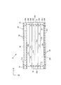
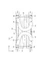
- FIG. 1 is a view of a non-wearing state of the mask 10 of one embodiment as viewed from the non-wearing surface 20Y side (the surface side opposite to the wearing surface 20X), and FIG. 2 is a mask 10 of one embodiment. It is the figure which looked at the non-wearing state from the wearing surface 20X side.
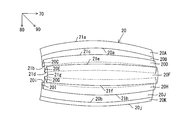
- FIG. 4 is a diagram showing the mask main body 20 in a non-wearing state
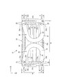
- FIG. 5 is a diagram showing the mask main body 20 in a wearing state
- FIG. 6 is a view taken along the line VI-VI in FIG.
- the “direction” used in the present specification is defined as follows.
- the “first direction 70” represents the longitudinal direction (width direction) of the mask main body 20 and corresponds to the wearer's left and right direction (referred to as “left and right direction”) in the mask wearing state.
- “One direction of the first direction 70” represents the direction from the left ear hook part (first ear hook part) 30 to the right ear hook part (second ear hook part) 40, and is worn in the mask wearing state. This corresponds to the direction from left to right as viewed from the person (referred to as “right direction”).
- “The other direction of the first direction” represents the direction from the right ear hooking portion (second ear hooking portion) 40 to the left ear hooking portion (first ear hooking portion) 30.
- the “second direction 80” represents a direction (height direction) intersecting the longitudinal direction of the mask main body 20, and corresponds to the wearer's vertical direction (referred to as “vertical direction”) when the mask is worn. .
- One direction of the second direction 80 represents the direction from the upper piece to the lower piece of the mask main body 20, and corresponds to the direction from the top to the bottom of the wearer in the mask wearing state (referred to as “down direction”).
- the other direction of the second direction 80 represents the direction from the lower piece to the upper piece of the mask main body 20, and corresponds to the direction from the bottom to the top of the wearer in the mask wearing state (referred to as “upward direction”).
- the “third direction 90” represents the front-rear direction of the mask body 20, and corresponds to the front-rear direction of the wearer in the mask wearing state (referred to as “front-rear direction”).
- One direction of the third direction 90 represents the direction from the non-wearing surface 20Y of the mask body 20 to the wearing surface 20X, and corresponds to the direction from the front to the back of the wearer in the mask wearing state (“backward direction” ").
- the other direction of the third direction 90 represents the direction from the wearing surface 20X to the non-wearing surface 20Y of the mask main body 20 and corresponds to the direction from the back to the front of the wearer in the mask wearing state (“front direction ").
- the mask 10 includes a mask main body 20, a left ear hook 30, and a right ear hook 40.
- the mask main body 20 is a member that covers the mouth and nose of the wearer.
- the left ear hook 30 and the right ear hook 40 are members that are hung on the wearer's left ear and right ear.
- the mask body 20 corresponds to the “mask body” of the present invention
- the left ear hook 30 corresponds to the “first ear hook” of the present invention
- the right ear hook 40 of the present invention This corresponds to the “second ear hook”.
- the mask main body 20 has a plurality of pleats extending along the first direction 70 (left-right direction), and is formed as a pleat type mask main body.
- sheet pieces formed in a square shape by the upper side 20a, the lower side 20b, the left side 20c, and the right side 20d are parallel to the upper side 20a and the lower side 20b (first The lines are sequentially folded along a plurality of folding lines 21a to 21j (parallel to the direction 70).
- the plurality of ridges 20B to 20J extending along the first direction 70 are arranged along the second direction 80 (vertical direction).
- the mask body 20 has a square shape in which the length (width) along the first direction 70 is W and the length (height) along the second direction 80 is H in a non-wearing state. Yes.
- the shape of the mask body 20 is not limited to a square.
- the shape retaining portion 50 is held by the folded pieces 20A and the collars 20B folded along the folding line 21a.
- the shape-retaining part 50 reduces the gap between the mask body 20 and the wearer's face by making the upper end of the mask body 20 correspond to the uneven shape of the wearer's face when wearing the mask. is there. It is preferable that the shape-retaining part 50 is easily bent and has a rigidity for maintaining the bent shape.
- the shape retaining portion 50 for example, a thin plate formed of synthetic resin or metal is used.
- the shape-retaining part 50 is held on the mask body 20 by various methods.
- the folded pieces 20 ⁇ / b> A and the flanges 20 ⁇ / b> B are joined by the joining portion 28 indicated by a broken line and the joining portion indicated by a black circle.
- the shape retaining piece 50 is held.
- the folded piece 20K folded by the folding line 21j is joined to the flange 20J by the joining portion 29. Adjacent ridges are joined at both ends along the first direction 70 by a left joint and a right joint 25 described later.
- the mask main body 20 is preferably made of a nonwoven fabric sheet made of thermoplastic fibers in three layers: an outer layer disposed on the anti-wearer side, a filter layer (intermediate layer), and an inner layer disposed on the wearer side. It is formed by a laminated sheet that is laminated.
- Non-woven sheets include, for example, polyethylene, polypropylene, polyethylene terephthalate, etc., air-through method, spunbond method, thermal bond method, spunlace method, point bond method, melt blow method, stitch bond method, chemical bond method, needle punch The one having a basis weight of 10 to 150 g / m 2 is used.
- the nonwoven fabric sheet forming the outer layer and the inner layer those having good breathability and touch are used, and as the nonwoven fabric sheet forming the filter layer, those having good breathability and barrier properties (collecting properties) are used. Is preferred.
- the left ear hook portion 30 and the right ear hook portion 40 are joined to the mask main body portion 20 in a state where the left ear hook portion 30 and the right ear hook portion 40 are arranged on the wearing surface (wearer side surface) 20X of the mask main body portion 20.
- mask main body 20, left ear hook 30 and left ear hook 40 are formed separately.
- the mask body 20, the left ear hook 30 and the left ear hook 40 may be formed integrally.
- the left ear hook 30 and the left ear hook 40 are overlapped with the mask main body 20 by folding one sheet piece.
- the left ear hook 30 and the right ear hook 40 are formed of sheet pieces.
- a nonwoven fabric sheet made of thermoplastic synthetic fiber can be used as in the mask main body portion 20, but a nonwoven fabric sheet having high stretchability is used. Is preferred.
- stretchable SB (spunbond) nonwoven fabric sheet stretchable SMS (spunbond / meltblown / spunbond composite nonwoven fabric sheet) nonwoven fabric sheet, (stretchable SB-film-SB) nonwoven fabric sheet, stretchable with a basis weight of 30 to 120 g / m 2
- a spunlace nonwoven fabric sheet, a stretchable HMA (hot melt backing agent) nonwoven fabric sheet, and the like are used.
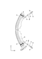
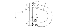
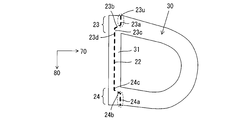
- the left ear hook 30 includes a base 31 and an edge (ear hook) 32 that extends from the base 31 and forms an opening 30a.
- the base portion 31 extends along the second direction 80, and includes a central base portion 31b, an upper end side base portion 31a disposed on the other direction side (upper side) along the second direction 80 from the central portion 31b, It has the lower end side base part 31c arrange
- the edge portion (ear hook portion) 32 extends from the upper end side base portion 31 a and the lower end side base portion 31 c of the base portion 31.
- the opening 30 a is formed by the notch 33.
- the edge (ear hook) 32 is hung on the wearer's left ear inserted in the opening 30a.
- the base 31 corresponds to the “first base” of the present invention
- the edge (ear hook) 32 corresponds to the “first edge” of the present invention.
- the “upper end side base portion 31a” corresponds to the “first upper end side base portion” of the present invention
- the central base portion 31b corresponds to the “first central base portion” of the present invention
- the lower end side base portion 31c is This corresponds to the “first lower end side base” of the present invention.
- the left ear hook 30 is disposed on the wearing surface 20 ⁇ / b> X of the mask main body 20 on the other direction side (left side) along the first direction 70.
- the left ear hook 30 is disposed on the wearing surface 20 ⁇ / b> X such that the edge 32 is disposed on one side (right side) along the first direction 70 from the base 31.
- a part of the base 31 of the left ear hook 30 is joined to the mask body 20 by the left joint.
- the left joint is constituted by a linear joint or a dotted joint formed along the second direction 80.
- a part of the base portion 31 is joined to the mask main body portion 20 by the left joint portion at the upper end side base portion 31a, the central base portion 31b, and the lower end side base portion 31c.
- the left joint includes an upper end joint 23 that joins the upper base 31a to the mask main body 20, a central joint 22 that joins the central base 31b to the mask main body 20, and a lower base 31c that serves as the mask main body 20. It has the lower end side joining part 24 joined to.
- the left joint is formed such that a portion closer to the edge 32 than the left joint can be folded back along the first direction 70 at the left joint.
- the left joint corresponds to the “first joint” of the present invention
- the upper end joint 23 corresponds to the “first upper joint” of the present invention
- the central joint 22 corresponds to the present invention.
- the lower end side joint 24 corresponds to the “first lower end joint” of the present invention.
- the right ear hook 40 has a base 41 and an edge (ear hook) 42 that extends from the base 41 and forms an opening 40a.
- the base portion 41 includes an upper end side base portion 41a, a central base portion 41b, and a lower end side base portion 41c that are sequentially arranged in one direction along the second direction 80.
- the edge portion (ear hook portion) 42 extends from the upper end side base portion 41a and the lower end side base portion 41c.
- the opening 40 a is formed by the notch 43.
- the edge (ear hook) 42 is hung on the wearer's right ear inserted into the opening 40a.
- the base 41 corresponds to the “second base” of the present invention
- the edge (ear hook) 42 corresponds to the “second edge” of the present invention
- the “upper end side base portion 41a” corresponds to the “second upper end side base portion” of the present invention
- the central base portion 41b corresponds to the “second central base portion” of the present invention
- the lower end side base portion 41c is This corresponds to the “second bottom side base” of the present invention.
- the right ear hook 40 is disposed on the wearing surface 20 ⁇ / b> X of the mask main body 20 on one side (right side) along the first direction 70.
- the right ear hooking portion 40 is arranged on the wearing surface 20 ⁇ / b> X such that the edge portion (ear hooking portion) 42 is arranged on the other direction side (left side) along the first direction 70 from the base portion 41. ing.
- the base 41 of the right ear hook 40 is joined to the mask body 20 by the right joint.
- the right joint is constituted by a linear joint or a dotted joint formed along the second direction 80.
- a part of the base portion 41 is joined to the mask main body portion 20 by the right joint portion at the upper end side base portion 41a, the central base portion 41b, and the lower end side base portion 41c.
- the right joint includes the upper joint 26 that joins the upper base 41a to the mask body 20, the central joint that joins the central base 41b to the mask body 20, and the lower base 41c to the mask body 20. It has the lower end side joining part 27 to join.
- the right joint is formed such that a portion closer to the edge 42 than the right joint can be folded back along the first direction 70 at the location of the right joint.
- the right joint corresponds to the “second joint” of the present invention
- the upper joint 26 corresponds to the “second upper joint” of the present invention
- the central joint corresponds to the “second joint” of the present invention.
- the lower end side joint portion 27 corresponds to the “second lower end side joint portion” of the present invention.
- the width of the connecting portion with (42) is set to L.
- the height H of the mask main body 20 is set to 70 mm to 110 mm
- the width L of the upper end base 31a (41a) and the lower end base 31c (41c) is set to 10 mm to 30 mm. That is, in the present embodiment, the edge 32 (42) of the left ear hook 30 (right ear hook 40) is formed as a band-shaped member having a width.
- the left ear hook portion 30 and the right ear hook portion 40 are disposed on the wearing surface 20X of the mask main body portion 20 on the left side portion and the right side portion, respectively, along the first direction.
- the edge portions (32, 42) are arranged on the center side along the first direction 70 from the base portions (31, 41), that is, the edge portions 32 and the right ear hook portions of the left ear hook portion 30.
- Forty edges 42 are arranged on the wearing surface 20 ⁇ / b> X so as to face each other along the first direction 70.
- a part of the base 31 of the right ear hook 30 is joined to the mask body 20 by the left joint, and a part of the base 41 of the right ear 40 is joined to the mask body 20 by the right joint.
- the left ear hook 30 and the right ear hook 40 are superimposed on the wearing surface 20X of the mask main body 20, so that the size (area) of the mask 10 is almost equal to the size (area) of the mask main body 20. Will be equal. Thereby, the mask 10 can be easily packaged and carried when not worn.
- the central portions of the flanges 20 ⁇ / b> B and 20 ⁇ / b> J at both ends along the second direction 80 are pulled along the second direction 80.
- the central portion along the first direction 70 of the ridges 20 ⁇ / b> B to 20 ⁇ / b> J expands along the second direction 80.
- the distance along the third direction 90 (front-rear direction) between the center flange 20F and the flanges 20A and 20B at both ends is increased. That is, the mask main body 20 has a three-dimensional shape.
- the left ear hook 30 and the right ear hook 40 are folded back in the first direction 70 (left-right direction). That is, the edge 32 of the left ear hook 30 is folded back to the left along the first direction 70. As a result, the portion of the left ear hook 30 that is closer to the edge 32 than the left joint is folded back at the location of the left joint. Further, the edge 42 of the right ear hook 40 is folded back to the right along the first direction 70. As a result, the portion of the right ear hooking portion 40 that is closer to the edge 42 than the right joint is folded back at the location of the right joint.
- the opening 30a of the left ear hook 30 is hung on the wearer's left ear, and the opening 40a of the right ear hook 40 is hung on the wearer's right ear.
- a part of the folded portion of the left ear hook 30 is disposed between the left joint and the wearer 60. That is, the left joint is covered with a part of the folded portion of the left ear hook 30.
- a part of the folded portion of the right ear hook 40 is disposed between the right joint and the wearer 60. That is, the right joint is covered with a part of the folded portion of the left ear hook 40.
- the left joint is also formed between the upper end base 31a and the lower end base 31c to form the left ear hook 30 and the mask main body 20.
- the joint strength can be increased.
- positioning aspect of the lower end side junction part 24 (27) in the base 31c (41c) is changed.
- the central joint portion 22 in the central base portion 31b (41b) is formed so that the position along the second direction 80 is substantially the same with respect to the first direction 70 (substantially parallel to the third direction 80). Yes.
- the upper end side joint part 23 (26) in the upper end side base part 31a (41a) and the lower end side joint part 24 (27) in the lower end side base part 31c (41c) are positioned along the second direction at the first position. Shifted with respect to direction 70.
- the upper joint 23 has a lower joint 23 d at one end (lower end) along the second direction 80 and an upper end at the other end (upper end) along the second direction 80. It is disposed on the opposite side of the edge portion 32 along the first direction 70 with respect to the joint portion 23u.
- the lower joint portion 26 d at the lower end along the second direction 80 is along the first direction 70 with respect to the upper joint portion 26 u at the upper end along the second direction 80. It is arranged on the opposite side to the edge 42.
- An appropriate joint is formed between the upper joint 23u (26u) and the lower joint 23d (26d).
- the lower end side joint portion 24 has an upper end upper joint portion 24 u along the second direction 80 in a first direction 70 with respect to a lower end lower joint portion 24 d along the second direction 80. Is disposed on the side opposite to the edge 32.
- the upper joint portion 27 u at the upper end along the second direction 80 is along the first direction 70 with respect to the lower joint portion 27 d at the lower end along the second direction 80. It is arranged on the opposite side to the edge 42.
- An appropriately shaped joint is formed between the upper joint 24u (27u) and the lower joint 24d (27d).
- shape and position (position along the 1st direction 70) of a left side junction part and a right side junction part can be set suitably, a part of part turned up in the location of a left side junction part and a right side junction part It is preferable to set so that the left joint and the right joint can be covered.
- the position of the upper-end-side joint portion 23 of the left-side joint portion extends along the second direction 80 from the position of the upper joint portion 23u at the upper end along the second direction 80.
- the lower end portion of the lower joint portion 23d is sequentially shifted in the other direction (left direction) along the first direction 70.
- the position of the upper end side joint portion 26 of the right side joint portion is changed from the position of the upper end upper joint portion 26u along the second direction 80 to the lower end lower joint portion 26d along the second direction 80.
- the position is sequentially shifted in one direction (right direction) along the first direction 70. This prevents a gap from being formed between the mask main body 20 and the wearer in the upper end side bases 31a and 41a when the mask is worn.
- the position of the lower end side joining portion 24 of the left side joining portion is changed from the position of the lower end lower joining portion 24d along the second direction 80 to the upper end upper joining portion 24u along the second direction 80.
- the position is sequentially shifted in the other direction (left direction) along the first direction 70.
- the position of the lower end side joint portion 27 of the right side joint portion 25 is changed from the position of the lower end lower joint portion 27d along the second direction 80 to the upper end upper joint portion 27u along the second direction 80.
- the upper end side joint portion (23, 26) and the lower end side joint portion (24, 27) can be formed in an appropriate shape, but the end portion side in the second direction 80 is the edge portion 32 (42). It is preferably formed at right angles (including substantially right angles) to the folding direction. That is, the upper end side joint portion 23 (26) is formed in parallel (including substantially parallel) to the second direction 80 at a location on the upper joint portion 23u (26u) side of the upper end in the second direction 80. . Further, the lower end side joint portion 24 (27) is formed in parallel (including substantially parallel) to the second direction 80 at a position on the lower joint portion 24d (27d) side of the lower end in the second direction 80. . For example, the upper end side joint portion 23 shown in FIG.
- the upper end side joint portion 23 shown in FIG. 8 is a joint formed at a location on the upper joint portion 23u side (a portion indicated by a wavy line) in parallel (including substantially parallel) to the second direction 80. It has the part 23a and the junction parts 23b and 23c formed along the step-like straight line. Further, the upper end side joint portion 23 shown in FIG.
- FIG. 9 is a joint formed at a location on the upper joint portion 23u side (a portion indicated by a wavy line) in parallel (including substantially parallel) to the second direction 80. It has the part 23a and the junction part 23b formed in parallel (it contains substantially parallel) to the 2nd direction 80 (joint part 23a and 23b are discontinuous).
- the end sides of the upper end side joint portions (23, 26) and the lower end side joint portions (24, 27) along the second direction 80 are set in the direction in which the edge portion 32 (42) is folded back (first).
- the strength against tensile stress in the folding direction (first direction 70) of the edge 32 (42) is increased.
- the upper end side base portion 31a (41a) and the central base portion 31b (41b) which are sequentially arranged in one direction (downward direction) along the second direction 80 on the left ear hook portion 30 (right ear hook portion 40).
- the base 31 (41) including the lower end side base 31c (41c) is provided, the shape of the base 31 (41) is not limited to this.
- Another embodiment 110 of the mask of the present invention is shown in FIG.
- the mask 110 according to the present embodiment includes a mask main body 120, a left ear hook 130 and a right ear hook 140.
- the mask main body 120 has the same configuration as the mask main body 20 described above.
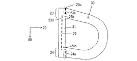
- the left ear hook 130 includes a base including an upper end base 131a and a lower end base 131c that are separated along the second direction 80, and an edge 132 extending from the upper end base 131a and the lower end base 131c. ing.
- the left ear hook 130 has an opening 130 a formed by a notch 133.
- the left ear hook 130 is worn by the mask main body 120 such that the edge 132 is disposed on one side (right side) along the first direction 70 from the upper end base 131a and the lower end base 131c. It is overlaid on the other side (left side) of the surface 120X.
- the left joint includes an upper end joint 123 that joins the upper base 131a to the mask body 120, a lower joint 124 that joins the lower base 131c to the mask body 120, and a flange 20B of the mask body 120. It has a central joint 122 for joining ⁇ 20J.
- the right ear hooking portion 140 includes a base portion including an upper end side base portion 141a and a lower end side base portion 141c that are separated along the second direction 80, and an edge portion 142 that extends from the upper end side base portion 141a and the lower end side base portion 141c.
- the right ear hook 140 has an opening 140 a formed by a notch 143.
- the right ear hooking portion 140 has a mask main body portion 120 such that the edge portion 142 is disposed on the other direction side (left side) along the first direction 70 from the upper end side base portion 141a and the lower end side base portion 141c. It is arrange
- the right joint includes an upper end joint 126 that joins the upper base 14a to the mask body 120, a lower joint 127 that joins the lower base 14c to the mask body 120, and the flanges 20B to 20J of the mask body 120.
- the central joint portion 125 is joined.
- the upper end side joint portion 123 (126) and the lower end side joint portion 124127) of the left side joint portion (right side joint portion) are edge portions 132 (142) from the upper end side joint portion 123 (126) and the lower end side joint portion 124 (127).
- the side portion is formed so that it can be folded back at the locations of the upper end side joint portion 123 (126) and the lower end side joint portion 124 (127).
- the upper ear side joint portion 123 and the lower end side joint 124 of the left ear hook 130 are located on the edge 132 side of the upper end side joint portion 123 and the lower end side joint 124. Wrap at the point of. Further, the portion of the right ear hooking portion 140 that is closer to the edge 142 than the upper end side joint portion 126 and the lower end side joint portion 127 is folded back at the location of the upper end side joint portion 126 and the lower end side joint portion 127. Accordingly, the upper end side joint portion 123 and the lower end side joint 124 are covered by a part of the portion closer to the edge portion 132 than the upper end side joint portion 123 and the lower end side joint 124.
- the upper end side joining portion 126 and the lower end side joining 127 are covered by a part of the portion on the edge 142 side from the upper end side joining portion 126 and the lower end side joining 127.
- the portion between the upper end side joint portion 123 (126) and the lower end side joint portion 124 (127) of the left side joint portion (right side joint portion) is not covered, but the upper end side joint portion 123 (126).
- the part corresponding to the lower end side junction part 124 (127) is covered. Thereby, it can prevent that the upper end side junction part 123 (126) and the lower end side junction part 124 (126) contact a wearer's skin at the time of mask wear. Even in this case, it can be worn better than the prior art.
- the mask when the mask is worn, it is possible to prevent a gap from being formed between the mask main body 120 and the wearer in the upper base portions 131a and 141a and further in the lower base portions 131c and 141c.
- the shape between the upper end side base part 131a (141a) and the lower side base part 131c (141c) of the base part 131 (141) can be changed suitably.
- the present invention is not limited to the configuration described in the embodiment, and various changes, additions, and deletions are possible.
- a mask main body portion, the left ear hook portion, and the right ear hook portion a mask main body portion, a left ear hook portion, and a right ear hook portion having various configurations can be used.
- the mask main body, the left ear hook, and the right ear hook can be formed using various materials and using various methods.
- various joining methods can be used as a method of joining the mask main body, the left ear hook, and the right ear hook.
- each ridge of the mask main body can be changed as appropriate.
- the shape, arrangement position, etc. of the left joint and the right joint can be appropriately changed.
- a junction part a continuous junction part can also be used and the junction part of the various shapes arrange
- Each configuration described in the embodiment can be used alone, or a plurality of appropriately selected configurations can be used in combination.
- the first ear hook has a first base and a first edge that extends from the first base and forms an opening; At least a part of the first base is joined to one surface of the mask body by the first joint, The first edge extends from the first base to one side of the first direction,
- the second ear hook has a second base and a second edge extending from the second base and forming an opening; At least a part of the second base part is joined to the one surface of the mask main body part by the second joint part, The second edge extends from the second base to the other direction side of the first direction, At least when the mask is worn, the first ear hook is folded back along the first direction at the location of the first joint, and the second ear hook is located at the location of the second joint.
- the mask is folded along the first direction.
- the first base portion has a first lower end side base portion and a first upper end side base upper end portion separated in a second direction intersecting the first direction, and the first lower end side base portion is The first upper end side base upper end portion is disposed on one side of the second direction, The first edge extends from the first upper end base and the first lower end base, At least a part of the first upper end base and at least a part of the first lower end base are joined to the one surface of the mask main body by the first joint,
- the second base portion has a second lower end side base portion and a second upper end side base portion that are separated in the second direction, and the second lower end side base portion is more than the first upper end side base portion.
- the second edge extends from the second upper end base and the second lower end base, At least a part of the second upper end side base part and at least a part of the second lower end side base part are joined to the one surface of the mask main body part by the second joint part.
- the first base includes a first upper end base, a first center base, and a first lower end base that are sequentially arranged along one direction of a second direction that intersects the first direction.
- the first edge extends from the first upper end base and the first lower end base, At least a part of the first base portion is the first upper end base portion, the first central base portion, and the first lower end side base portion, and the one of the mask main body portions by the first joint portion.
- the second base has a second upper end side base, a second center base, and a second lower end side base arranged in order along the one direction of the second direction,
- the second edge extends from the second upper end base and the second lower end base, At least a part of the second base portion is the second upper end side base portion, the second central base portion, and the second lower end side base portion, and the one of the mask main body portions by the second joint portion.
- a mask characterized by being bonded to a surface.
- a mask according to claim 1 wherein At least when wearing a mask, a part of the first ear hook is disposed between the first joint and the wearer, and a part of the second joint is the second joint.
- a mask characterized in that it is placed between wearers.
- the mask main body has a plurality of ridges extending along the first direction, and the plurality of ridges have an end on the other direction side in the first direction at the first joint portion. And the end on the one direction side in the first direction is joined by the second joint,
- the first edge extends in a strip shape from the first base,
- the mask, wherein the second edge portion extends from the second base portion in a band shape.
- Has an edge of The second ear hooking portion extends from the second base portion, the second base portion being at least partially joined to the mask main body portion by the second joint portion, and forming a second opening.
- Has an edge of At least when wearing a mask a part of the first ear hook is disposed between the first joint and the wearer, and a part of the second joint is the second joint.
- a mask characterized in that it is placed between wearers.
Priority Applications (4)
| Application Number | Priority Date | Filing Date | Title |
|---|---|---|---|
| EP11744776A EP2537559A1 (en) | 2010-02-19 | 2011-02-18 | Mask |
| KR1020127024442A KR101604166B1 (ko) | 2010-02-19 | 2011-02-18 | 마스크 |
| US13/579,518 US20130047995A1 (en) | 2010-02-19 | 2011-02-18 | Mask |
| CN201180009896.4A CN102762261B (zh) | 2010-02-19 | 2011-02-18 | 口罩 |
Applications Claiming Priority (2)
| Application Number | Priority Date | Filing Date | Title |
|---|---|---|---|
| JP2010-035449 | 2010-02-19 | ||
| JP2010035449A JP5436262B2 (ja) | 2010-02-19 | 2010-02-19 | マスク |
Publications (1)
| Publication Number | Publication Date |
|---|---|
| WO2011102490A1 true WO2011102490A1 (ja) | 2011-08-25 |
Family
ID=44483075
Family Applications (1)
| Application Number | Title | Priority Date | Filing Date |
|---|---|---|---|
| PCT/JP2011/053573 WO2011102490A1 (ja) | 2010-02-19 | 2011-02-18 | マスク |
Country Status (6)
| Country | Link |
|---|---|
| US (1) | US20130047995A1 (zh) |
| EP (1) | EP2537559A1 (zh) |
| JP (1) | JP5436262B2 (zh) |
| KR (1) | KR101604166B1 (zh) |
| CN (1) | CN102762261B (zh) |
| WO (1) | WO2011102490A1 (zh) |
Cited By (1)
| Publication number | Priority date | Publication date | Assignee | Title |
|---|---|---|---|---|
| JP2018003189A (ja) * | 2016-06-30 | 2018-01-11 | ユニ・チャーム株式会社 | マスク |
Families Citing this family (29)
| Publication number | Priority date | Publication date | Assignee | Title |
|---|---|---|---|---|
| US20080271739A1 (en) | 2007-05-03 | 2008-11-06 | 3M Innovative Properties Company | Maintenance-free respirator that has concave portions on opposing sides of mask top section |
| US9770611B2 (en) | 2007-05-03 | 2017-09-26 | 3M Innovative Properties Company | Maintenance-free anti-fog respirator |
| JP5972092B2 (ja) * | 2012-08-06 | 2016-08-17 | サンエムパッケージ 株式会社 | マスク |
| JP6068135B2 (ja) * | 2012-08-10 | 2017-01-25 | ユニ・チャーム株式会社 | マスク |
| US10786695B2 (en) | 2013-07-17 | 2020-09-29 | The Smartmask Llc | Protective respiratory mask with electronic system |
| US20150020815A1 (en) * | 2013-07-17 | 2015-01-22 | Pamela Gabriel | Protective Mask with Imbedded Functionality |
| KR20180083886A (ko) * | 2015-11-11 | 2018-07-23 | 쓰리엠 이노베이티브 프로퍼티즈 캄파니 | 형상 유지형 편평-절첩식 호흡기 |
| JP6374432B2 (ja) * | 2016-04-15 | 2018-08-15 | ユニ・チャーム株式会社 | 使い捨てマスク |
| JP6859206B2 (ja) * | 2017-06-06 | 2021-04-14 | 花王株式会社 | シート状マスクの製造方法 |
| CN108211157A (zh) * | 2017-07-11 | 2018-06-29 | (株)喜途意成进 | 一种无缝型口罩及其制作方法 |
| TWI645883B (zh) * | 2017-07-24 | 2019-01-01 | 台灣康匠製造股份有限公司 | 具展翼之口罩及其製造工序 |
| JP6608472B2 (ja) * | 2018-02-19 | 2019-11-20 | アイリスオーヤマ株式会社 | マスク |
| JP2019189989A (ja) * | 2018-04-27 | 2019-10-31 | 花王株式会社 | マスク、包装体及び包装方法 |
| JP2020002510A (ja) * | 2018-06-29 | 2020-01-09 | 桐灰化学株式会社 | マスク |
| JP6816075B2 (ja) * | 2018-09-05 | 2021-01-20 | スズラン株式会社 | マスク、およびマスクの製造方法 |
| JP7289494B2 (ja) * | 2018-10-12 | 2023-06-12 | 興研株式会社 | 使い捨てマスク |
| USD885559S1 (en) | 2019-03-04 | 2020-05-26 | The Smartmask Llc | Respiratory mask |
| JP7346255B2 (ja) * | 2019-11-13 | 2023-09-19 | 小林製薬株式会社 | アイマスク型の温熱具 |
| JP7437940B2 (ja) | 2020-01-08 | 2024-02-26 | 白元アース株式会社 | マスク |
| WO2021230208A1 (ja) * | 2020-05-12 | 2021-11-18 | 株式会社瑞光 | マスク及びその製造方法 |
| JP7296918B2 (ja) * | 2020-05-29 | 2023-06-23 | 大王製紙株式会社 | マスク |
| US11284654B2 (en) * | 2020-06-10 | 2022-03-29 | Under Armour, Inc. | Breathable face mask |
| USD910929S1 (en) * | 2020-06-30 | 2021-02-16 | Joseph Chi Won | Face mask |
| JP7210512B2 (ja) * | 2020-07-31 | 2023-01-23 | 大王製紙株式会社 | マスク |
| KR102555641B1 (ko) * | 2020-12-02 | 2023-07-13 | 송철규 | 마스크 고속 제조장치 |
| JP2022142086A (ja) | 2021-03-16 | 2022-09-30 | 大王製紙株式会社 | マスク |
| JP2022153831A (ja) | 2021-03-30 | 2022-10-13 | 大王製紙株式会社 | マスク、及びマスクの製造方法 |
| GB202105679D0 (en) * | 2021-04-21 | 2021-06-02 | Logicor Us Ltd | Face mask |
| KR102443638B1 (ko) * | 2021-06-25 | 2022-09-16 | 크린킵 주식회사 | 마스크 제조방법 |
Citations (4)
| Publication number | Priority date | Publication date | Assignee | Title |
|---|---|---|---|---|
| JPH0334195A (ja) | 1989-06-29 | 1991-02-14 | Toshiba Corp | 半導体記憶装置 |
| JP2003010351A (ja) * | 2001-06-29 | 2003-01-14 | Mitsuyo Tanaka | マスク |
| JP3130364U (ja) * | 2006-07-20 | 2007-03-29 | 時枝 氏井 | 簡易防煙マスク |
| JP2008093428A (ja) * | 2007-09-28 | 2008-04-24 | Uni Charm Corp | マスク |
Family Cites Families (5)
| Publication number | Priority date | Publication date | Assignee | Title |
|---|---|---|---|---|
| JPH061326Y2 (ja) * | 1990-04-17 | 1994-01-12 | 功 庄田 | 木工用サンディングホイール |
| US7725948B2 (en) * | 2004-12-22 | 2010-06-01 | Kimberly-Clark Woldwide, Inc. | Face mask with offset folding for improved fluid resistance |
| US20070068529A1 (en) * | 2005-09-27 | 2007-03-29 | Suresh Kalatoor | Respirator that uses a polymeric nose clip |
| CN200951271Y (zh) * | 2006-08-31 | 2007-09-26 | 玉川卫生用品(上海)有限公司 | 一种多折口罩 |
| CN101537237B (zh) * | 2008-03-21 | 2011-12-28 | 康那香企业股份有限公司 | 具有弹性不织布耳带的口罩的制造方法 |
-
2010
- 2010-02-19 JP JP2010035449A patent/JP5436262B2/ja active Active
-
2011
- 2011-02-18 CN CN201180009896.4A patent/CN102762261B/zh active Active
- 2011-02-18 US US13/579,518 patent/US20130047995A1/en not_active Abandoned
- 2011-02-18 EP EP11744776A patent/EP2537559A1/en not_active Withdrawn
- 2011-02-18 KR KR1020127024442A patent/KR101604166B1/ko active IP Right Grant
- 2011-02-18 WO PCT/JP2011/053573 patent/WO2011102490A1/ja active Application Filing
Patent Citations (4)
| Publication number | Priority date | Publication date | Assignee | Title |
|---|---|---|---|---|
| JPH0334195A (ja) | 1989-06-29 | 1991-02-14 | Toshiba Corp | 半導体記憶装置 |
| JP2003010351A (ja) * | 2001-06-29 | 2003-01-14 | Mitsuyo Tanaka | マスク |
| JP3130364U (ja) * | 2006-07-20 | 2007-03-29 | 時枝 氏井 | 簡易防煙マスク |
| JP2008093428A (ja) * | 2007-09-28 | 2008-04-24 | Uni Charm Corp | マスク |
Cited By (1)
| Publication number | Priority date | Publication date | Assignee | Title |
|---|---|---|---|---|
| JP2018003189A (ja) * | 2016-06-30 | 2018-01-11 | ユニ・チャーム株式会社 | マスク |
Also Published As
| Publication number | Publication date |
|---|---|
| US20130047995A1 (en) | 2013-02-28 |
| JP5436262B2 (ja) | 2014-03-05 |
| KR20130036004A (ko) | 2013-04-09 |
| KR101604166B1 (ko) | 2016-03-16 |
| CN102762261A (zh) | 2012-10-31 |
| CN102762261B (zh) | 2015-01-14 |
| EP2537559A1 (en) | 2012-12-26 |
| JP2011167419A (ja) | 2011-09-01 |
Similar Documents
| Publication | Publication Date | Title |
|---|---|---|
| JP5436262B2 (ja) | マスク | |
| JP5318002B2 (ja) | マスク | |
| JP6499032B2 (ja) | 使い捨てマスク | |
| JP5901900B2 (ja) | マスク | |
| JP4831430B2 (ja) | マスク | |
| JP2007021031A5 (zh) | ||
| JP2008093428A (ja) | マスク | |
| JP4990228B2 (ja) | 衛生マスク | |
| JP4717538B2 (ja) | マスク | |
| JP2008055036A (ja) | マスク | |
| JP4996264B2 (ja) | マスク | |
| JP2011120761A (ja) | 衛生マスク | |
| JP2007021027A5 (zh) | ||
| JP3212966U (ja) | マスク | |
| JP2018083988A (ja) | マスク | |
| JP3162028U (ja) | サイドフィット加工したマスク | |
| JP2020084388A (ja) | マスク | |
| JP4921305B2 (ja) | マスク | |
| JP5837252B1 (ja) | 使い捨てマスク | |
| JP3156690U (ja) | マスク | |
| JP6081725B2 (ja) | マスク | |
| JP5074746B2 (ja) | 使い捨て衛生マスク | |
| JP5901899B2 (ja) | マスク | |
| CN212088208U (zh) | 口罩 |
Legal Events
| Date | Code | Title | Description |
|---|---|---|---|
| WWE | Wipo information: entry into national phase |
Ref document number: 201180009896.4 Country of ref document: CN |
|
| 121 | Ep: the epo has been informed by wipo that ep was designated in this application |
Ref document number: 11744776 Country of ref document: EP Kind code of ref document: A1 |
|
| NENP | Non-entry into the national phase |
Ref country code: DE |
|
| WWE | Wipo information: entry into national phase |
Ref document number: 2011744776 Country of ref document: EP |
|
| ENP | Entry into the national phase |
Ref document number: 20127024442 Country of ref document: KR Kind code of ref document: A |
|
| WWE | Wipo information: entry into national phase |
Ref document number: 13579518 Country of ref document: US |