WO2011102268A1 - 半導体ガスの製造方法 - Google Patents
半導体ガスの製造方法 Download PDFInfo
- Publication number
- WO2011102268A1 WO2011102268A1 PCT/JP2011/052702 JP2011052702W WO2011102268A1 WO 2011102268 A1 WO2011102268 A1 WO 2011102268A1 JP 2011052702 W JP2011052702 W JP 2011052702W WO 2011102268 A1 WO2011102268 A1 WO 2011102268A1
- Authority
- WO
- WIPO (PCT)
- Prior art keywords
- monofluoromethane
- catalyst
- producing
- fluoride
- difluoroacetic acid
- Prior art date
- Legal status (The legal status is an assumption and is not a legal conclusion. Google has not performed a legal analysis and makes no representation as to the accuracy of the status listed.)
- Ceased
Links
Images


Classifications
-
- C—CHEMISTRY; METALLURGY
- C07—ORGANIC CHEMISTRY
- C07C—ACYCLIC OR CARBOCYCLIC COMPOUNDS
- C07C17/00—Preparation of halogenated hydrocarbons
- C07C17/361—Preparation of halogenated hydrocarbons by reactions involving a decrease in the number of carbon atoms
-
- C—CHEMISTRY; METALLURGY
- C07—ORGANIC CHEMISTRY
- C07C—ACYCLIC OR CARBOCYCLIC COMPOUNDS
- C07C51/00—Preparation of carboxylic acids or their salts, halides or anhydrides
- C07C51/58—Preparation of carboxylic acid halides
-
- H—ELECTRICITY
- H10—SEMICONDUCTOR DEVICES; ELECTRIC SOLID-STATE DEVICES NOT OTHERWISE PROVIDED FOR
- H10P—GENERIC PROCESSES OR APPARATUS FOR THE MANUFACTURE OR TREATMENT OF DEVICES COVERED BY CLASS H10
- H10P50/00—Etching of wafers, substrates or parts of devices
- H10P50/20—Dry etching; Plasma etching; Reactive-ion etching
- H10P50/28—Dry etching; Plasma etching; Reactive-ion etching of insulating materials
- H10P50/282—Dry etching; Plasma etching; Reactive-ion etching of insulating materials of inorganic materials
- H10P50/283—Dry etching; Plasma etching; Reactive-ion etching of insulating materials of inorganic materials by chemical means
Definitions
- the present invention relates to a method for producing monofluoromethane (CH 3 F), and more specifically, difluoroacetic acid fluoride which is useful as an intermediate for medical and agricultural chemicals while producing monofluoromethane useful as a semiconductor gas such as an etching agent and a cleaning agent.
- the present invention relates to a method for producing the derivative simultaneously.
- Patent Document 1 As a method for producing monofluoromethane, a method is known in which methyl chloride is fluorinated with hydrogen fluoride (chlorine-fluorine exchange) on a catalyst (Patent Document 1). Although this method has high selectivity, it is difficult to say that it is an efficient production method with low conversion.
- the target product monofluoromethane (boiling point: ⁇ 78 ° C.) and by-product hydrogen chloride (boiling point: ⁇ 85 ° C.) are not only close to each other in boiling point, but also exhibit an azeotropic phenomenon. Distillation separation is not easy and a complicated purification process is used (Patent Document 2).
- Non-patent Document 1 a method of fluorinating methyl iodide using a tetra-n-butylammonium salt is known (Non-patent Document 1), but starting materials are difficult to obtain compared to the method of Patent Document 1.
- the starting materials of these methods are not only highly toxic, but also are ozone-depleting substances, so care must be taken in handling.
- Patent Document 2 when chlorine, bromine, iodine, etc., which are highly reactive with radicals, are mixed into the product, the etching rate is affected, so these halogen-containing substances should be used as raw materials. Is not desirable.
- Patent Document 3 discloses that as a by-product, alkyl fluoride and its fluoride are synthesized during the synthesis of difluoroacetic acid fluoride or difluoroacetic acid ester by contacting 1-alkoxy-1,1,2,2-tetrafluoroethane with a metal oxide catalyst. Although it is described that olefins and hydrogen fluoride, which are decomposition products of alkyl fluoride, are produced, there is no description about the yield, purity, isolation and purification method, utilization method, etc. of monofluoromethane.
- the fluorine-containing semiconductor gas produced by the halogen-fluorine exchange reaction often contains halogens other than fluorine, such as chlorine, bromine, and iodine, which are avoided in the semiconductor device production process due to the raw materials, It is known that various problems occur in precise etching such as anisotropic etching. Therefore, the present invention provides a method for practically and efficiently producing monofluoromethane substantially free of halogen other than fluorine.
- the present inventors examined a method for producing monofluoromethane. From the pyrolysis product produced by bringing 1-methoxy-1,1,2,2-tetrafluoroethane into contact with a catalyst and thermally decomposing it. We have found that high yield and high purity monofluoromethane can be isolated easily.
- the present invention is as follows.
- Invention 1 wherein the step of recovering monofluoromethane includes a step of liquefying a part of the thermal decomposition product and separating monofluoromethane.
- Invention 3 Invention 2 in which a part of the pyrolysis product is liquefied by cooling.
- Invention 1 wherein the step of recovering monofluoromethane includes a step of absorbing difluoroacetic acid fluoride in a solvent inert to difluoroacetic acid fluoride.
- Invention 6 Invention 5 wherein the solvent inert to difluoroacetic acid fluoride is a hydrocarbon compound.
- Invention 7 Invention 1 in which the step of recovering monofluoromethane includes a step of contacting with a compound active against difluoroacetic acid fluoride.
- Invention 8 Invention 7 wherein the compound active against difluoroacetic acid fluoride is water, alcohols, primary amines, secondary amines or ⁇ unsaturated carboxylic acid esters.
- Invention 9 Invention 7 or 8 wherein a solvent is present in the step of contacting with a compound active against difluoroacetic acid fluoride.
- invention 10 Inventions 7 to 9 wherein a basic substance is present in the step of contacting with a compound active against difluoroacetic acid fluoride.
- Invention 11 Pyrolysis process is carried out using metal oxide, partially fluorinated metal oxide, metal fluoride, untreated comb as phosphoric acid or untreated comb or fluorinated phosphate as catalyst. Inventions 1 to 10 in which the temperature is 100 ° C. to 400 ° C.
- Invention 12 Inventions 1 to 10 wherein the pyrolysis step uses alumina, partially fluorinated alumina or aluminum fluoride as a catalyst, and the pyrolysis temperature is 130 ° C. to 260 ° C.
- Invention 15 Inventions 1 to 6 comprising the steps of obtaining monofluoromethane and separately obtaining difluoroacetic acid fluoride.
- FIG. 2 is a schematic view of an apparatus used in Examples 1 to 21.
- FIG. 6 is a schematic view of an apparatus used in Examples 22 to 24 and Reference Examples 5 and 6.
- FIG. 26 is a schematic view of an apparatus used in Example 26.
- FIG. 10 is a schematic view of an apparatus used in Examples 27 and 28.
- the production method of the present invention does not contain chlorine or the like as a raw material, high-purity monofluoromethane that does not contain halogen other than fluorine as impurities can be produced.
- high-purity monofluoromethane that can be used as an etching agent or a cleaning agent in the semiconductor industry can be produced without performing purification operations by complicated means.
- 1-methoxy-1,1,2,2-tetrafluoroethane having a low impact on the global environment such as ozone layer destruction and low toxicity is used as a raw material, so that the production is highly practical. Is the method.
- difluoroacetic acid fluoride obtained as a by-product has a use as a pharmaceutical and agrochemical intermediate, the raw materials can be used effectively.
- 1-methoxy-1,1,2,2-tetrafluoroethane is thermally decomposed in the presence of a catalyst to obtain a thermal decomposition product containing monofluoromethane, and this thermal decomposition product
- monofluoromethane is separated from the product.
- the reaction involving this method is represented by the following equation: CHF 2 CF 2 OCH 3 ⁇ CH 3 F + CHF 2 COF
- 1-Methoxy-1,1,2,2-tetrafluoroethane which is a raw material of the present invention, can be obtained by a known production method.
- 1-methoxy-1,1,2,2-tetrafluoroethane can be synthesized by reacting methanol and tetrafluoroethylene in the presence of potassium hydroxide (J. Am. Chem. Soc., 73, 1329). (1951)).
- the thermal decomposition catalyst according to the present invention is a metal oxide, partially fluorinated metal oxide, metal fluoride, phosphoric acid or phosphate, and is used as a solid catalyst.
- the metal oxide examples include alumina, titania, zirconia and the like, and alumina that is easily available is particularly preferable.
- Alumina can be formed into a molded product of any size and shape by adding ammonia to an aqueous solution of an aluminum salt such as aluminum sulfate or aluminum nitrate to precipitate aluminum hydroxide, and molding and drying.
- an aluminum salt such as aluminum sulfate or aluminum nitrate to precipitate aluminum hydroxide
- ⁇ -alumina having a large specific surface area is preferable.
- Commercially available ⁇ -alumina or ⁇ -alumina can be used as a desiccant, adsorbent, catalyst carrier and the like.
- the metal oxide Prior to use, the metal oxide is partially fluorinated with hydrogen fluoride, organic fluorine compound gas, etc., partially replacing oxygen atoms with fluorine atoms to form partially fluorinated metal oxides. It is preferable to prevent fluorination and decrease in activity. Without this fluorination treatment, when the monofluoromethane or raw material generated by pyrolysis comes into contact with the metal oxide at the reaction temperature, the catalyst becomes fluorinated and the catalytic activity becomes unstable. On the other hand, monofluoromethane or difluoroacetic acid Fluoride can be decomposed and increase by-products of hydrocarbons such as methane. For the fluorination treatment, hydrogen fluoride is preferable because it is not only inexpensive as a fluorinating agent but also does not cause carbon deposition by the treatment.
- metal fluorides aluminum fluoride (AlF 3 ) or calcium fluoride (CaF 2 ) is particularly preferable. These fluorides are preferably anhydrous. When preparing from a hydrous material, it is preferable to perform a dehydration process by heating. In these catalysts, the metal is completely fluorinated, so the phenomenon does not occur as in the case of metal oxides in which the catalyst extracts fluorine from the raw material or product, but even in metal fluorides, hydrogen fluoride The fluorination treatment with the above is preferable because it activates the catalyst surface.
- phosphoric acid or phosphate As a catalyst for thermal decomposition, phosphoric acid or phosphate (in this specification, phosphoric acid and phosphate may be collectively referred to as “phosphate”) is also preferable.
- the phosphate may be supported on a carrier.
- phosphoric acid any of orthophosphoric acid, polyphosphoric acid, and metaphosphoric acid may be used.
- polyphosphoric acid include pyrophosphoric acid.
- Phosphate is the metal salt of these phosphoric acids. Since it is easy to handle, orthophosphoric acid is preferred.
- a phosphate consists of hydrogen, aluminum, boron, alkaline-earth metal, titanium, zirconium, lanthanum, cerium, yttrium, rare earth metal, vanadium, niobium, chromium, manganese, iron, cobalt, nickel And at least one metal phosphate selected from the group.
- the phosphate as the main component is aluminum phosphate, cerium phosphate, boron phosphate, titanium phosphate, zirconium phosphate, chromium phosphate, or the like. These also preferably contain other metals.
- cerium, lanthanum, yttrium, chromium, iron, cobalt, nickel and the like are preferable, but cerium, iron and yttrium are more preferable.
- aluminum phosphate, cerium phosphate, and phosphates composed of these two types are more preferable.
- the method for preparing the phosphate catalyst is not particularly limited, and a commercially available phosphate may be used as it is, or may be prepared by a general precipitation method.
- a specific preparation method of the precipitation method for example, dilute aqueous ammonia is added dropwise to a mixed aqueous solution of metal nitrate (in the case of a plurality of metals, a solution of each salt) and phosphoric acid to adjust the pH. Adjust to precipitate and leave to mature as needed. Then, it is washed with water and it is confirmed that it has been sufficiently washed with the conductivity of the washing water. In some cases, a portion of the slurry is taken and measured to determine the cations. It is then filtered and dried.
- the drying temperature is preferably 80 ° C to 150 ° C. More preferably, it is 100 ° C to 130 ° C.
- the obtained dried product is pulverized to have a uniform particle size, or further pulverized and formed into pellets or spheres.
- firing is performed in an air or nitrogen atmosphere at 200 ° C. to 1500 ° C.
- the firing is preferably performed at 400 to 1300 ° C, more preferably at 500 to 900 ° C.
- the firing time depends on the temperature, it is about 1 to 50 hours, preferably about 2 to 24 hours. Since the calcination treatment is a treatment necessary for stabilizing the phosphate, it may not exhibit sufficient catalytic activity at the initial stage of the reaction when it is treated at a temperature lower than the temperature of the thermal decomposition reaction or when the treatment time is short. is there. In addition, it is not preferable to perform the calcination treatment at a temperature higher than the above temperature range or for a long time because not only excessive heating energy is required but also crystallization of the catalyst is caused and the catalytic activity is impaired.
- the operation of adding a metal component other than the main component is preferably performed using a metal salt, and is used as the metal nitrate, chloride, oxide, phosphate or the like.
- nitrate is preferable because of its high water solubility.
- nitrate is preferable because of its high water solubility.
- nitrate is preferable because of its high water solubility.
- limiting in particular in addition amount Generally it is 1 gram atom or less with respect to 1 gram atom of phosphorus, Preferably it is 0.5 gram atom or less. More preferably, it is 0.3 gram atom or less.
- the addition of these metal components may be performed in the metal salt solution before precipitation during catalyst preparation, or may be performed by immersing the phosphate catalyst after catalyst calcination in the metal salt solution.
- Metal oxides, partially fluorinated metal oxides, metal fluorides, phosphoric acid or phosphate catalysts can be used as powders as fluidized bed catalysts, but they are compressed into pellets. It can also be used as a fixed bed catalyst.
- a binder may be added when tableting the powder.
- saccharides, polymer compounds, metal oxides and the like that have been generally used can be used.
- phosphoric acid such as orthophosphoric acid, polyphosphoric acid, and metaphosphoric acid is added, the catalytic activity is not impaired. Can be compressed into tablets.
- the active component can be used as it is as a catalyst, but it is preferable to use it while it is supported on a carrier.
- the carrier include metal oxides such as alumina, titania, zirconia, zirconia sulfate (ZrO (SO 4 )), silicon carbide, silicon nitride, activated carbon and the like, and activated carbon is particularly preferable.
- the catalyst carrying phosphoric acid can be prepared by immersing the carrier in a phosphoric acid solution and impregnating it, or by drying the one coated or adsorbed by spraying.
- the phosphate When the phosphate is supported, it can be prepared by impregnating a single solution of one or more compounds to be supported, or coating or adsorbing by a spray and then drying. In addition, after impregnating the first compound solution and drying, it is possible to impregnate another compound solution.
- the phosphate-carrying catalyst can also be prepared by performing the preparation method by the precipitation method of phosphate described above in the presence of a support such as activated carbon.
- Activated carbon is made from plant-based, peat, lignite, lignite, bituminous coal, anthracite, etc. that are made from wood, charcoal, coconut husk, palm kernel charcoal, raw ash, etc. Any of petroleum type or synthetic resin type such as carbonized polyvinylidene chloride may be used. These activated carbons can be selected and used. For example, activated carbon produced from bituminous coal (BPL granular activated carbon manufactured by Toyo Calgon), coconut shell charcoal (granular white birch GX, SX, CX, XRC manufactured by Nippon Enviro Chemicals), Toyo Calgon PCB) and the like, but is not limited thereto. The shape and size are usually used in a granular form, but can be used within a normal knowledge range as long as it is suitable for a reactor such as a sphere, fiber, powder, or honeycomb.
- the activated carbon used in the present invention is preferably activated carbon having a large specific surface area.
- the specific surface area of the activated carbon is sufficient within the range of specifications of commercial products, but is 400 m 2 / g to 3000 m 2 / g, and preferably 800 m 2 / g to 2000 m 2 / g.
- a basic aqueous solution such as ammonium hydroxide, sodium hydroxide, potassium hydroxide or the like for about 10 hours or longer at room temperature or when activated carbon is used as a catalyst support.
- Pretreatment with an acid such as nitric acid, hydrochloric acid, or hydrofluoric acid may be performed to activate the carrier surface and remove ash in advance.
- the phosphate catalyst or phosphate-carrying catalyst of the present invention is also contacted with a fluorine-containing compound such as hydrogen fluoride, fluorinated hydrocarbon or fluorinated chlorinated hydrocarbon in advance before use. This is effective for prolonging the life of the catalyst and preventing abnormal reactions because it prevents changes in the composition of the catalyst during the reaction.
- a fluorine-containing compound such as hydrogen fluoride, fluorinated hydrocarbon or fluorinated chlorinated hydrocarbon
- the carrier of the present invention such as a metal oxide may contain a metal component and atoms other than oxygen, and alumina (Al 2 O 3 ), zirconia (ZrO 2 ), titania (TiO 2 ), and zirconia sulfate.
- alumina Al 2 O 3
- ZrO 2 zirconia
- TiO 2 titania
- zirconia sulfate at least one metal oxide selected from the group consisting of these partially fluorinated oxides is preferred, and alumina and partially fluorinated alumina are particularly preferred in terms of catalyst activity and catalyst life.
- the ratio of oxygen atoms and fluorine atoms in the catalyst is not particularly limited.
- partially fluorinated or chlorinated oxides such as alumina and zirconia as described above are oxides such as “alumina” and “zirconia”. May be displayed by name.
- Fluorination treatment with hydrogen fluoride can significantly increase the activity of the reaction. It is preferably carried out by contacting with hydrogen fluoride at least at a temperature higher than the thermal decomposition temperature.
- the temperature is about 200 to 600 ° C., preferably about 250 to 500 ° C., more preferably 300 to 400 ° C.
- the temperature is about 200 to 700 ° C, preferably about 250 to 600 ° C, more preferably 300 to 550 ° C.
- the temperature is about 200 to 600 ° C, preferably about 250 to 500 ° C, more preferably 300 to 400 ° C. In any case, if the temperature is lower than 200 ° C., it takes time for the treatment, and it is not preferable to perform the treatment beyond the maximum temperature range because excessive heating energy is required.
- the treatment time is not limited because it relates to the treatment amount and the treatment temperature, but it is about 1 hour to 10 days, preferably about 3 hours to 7 days.
- a catalyst obtained by treating aluminum fluoride, calcium fluoride, alumina, or aluminum phosphate with hydrogen fluoride is particularly preferable.
- the gas phase continuous flow system is mentioned as the most preferable form, but it is not limited to this.
- the dimensions and shape of the reactor can be appropriately changed according to the amount of reactants and the like.
- an inert gas can be allowed to exist under the reaction conditions, but the separation operation of monofluoromethane and the inert gas becomes complicated.
- the pyrolysis temperature depends on the type of catalyst or the contact time, but is usually 100 to 400 ° C, preferably 110 to 350 ° C, more preferably 130 to 320 ° C, still more preferably 130 to 260 ° C, and 140 to 200 ° C is particularly preferred. If the reaction temperature is less than 100 ° C., the selectivity for monofluoromethane is high, but the conversion is low, so the productivity is low and this is not preferred. When the reaction temperature exceeds 400 ° C., the conversion rate is almost 100%. However, the reaction apparatus requires severe heat resistance and requires excessive heating energy, which is not economically undesirable and causes side reactions. There is.
- the produced difluoroacetic acid fluoride may decompose into trifluoromethane (CHF 3 ) when it contacts the catalyst at a high temperature.
- CHF 3 trifluoromethane
- the reaction time depends on the reaction temperature, but is usually 0.1 to 1000 seconds, preferably 1 to 500 seconds, and more preferably 10 to 300 seconds. When the reaction time is shorter than 0.1 seconds, the conversion rate may be lowered. On the other hand, when the reaction time is longer than 1000 seconds, the productivity is lowered. Conversely, even in a very slow reaction region where the reaction temperature is less than 100 ° C., it is possible to increase the conversion rate by extending the contact time.
- the reaction pressure is not particularly limited, and may be normal pressure, reduced pressure, or increased pressure.
- a pressure of about 0.05 to 0.5 MPa (0.5 to 5 atmospheres) is preferable, and usually a pressure in the vicinity of atmospheric pressure that facilitates operation is preferable.
- the conversion rate of 1-methoxy-1,1,2,2-tetrafluoroethane can be substantially 100%. Since the conversion rate correlates with the byproduct rate of trifluoromethane, when it is desired to reduce the production of trifluoromethane and simplify the purification process, it is preferably 30 to 95%, more preferably 50 to 90%. When the conversion rate is less than 30%, the productivity of monofluoromethane is low, and when it exceeds 95%, the by-product of trifluoromethane may increase.
- the catalyst of the thermal decomposition reaction may generate coking over time, and the activity of the catalyst may decrease.
- the activity-reduced catalyst can be easily regenerated by contacting with oxygen (oxygen treatment) at 200 ° C. to 1200 ° C., preferably 400 ° C. to 800 ° C.
- oxygen treatment it is convenient to circulate oxygen while the catalyst is loaded in the reaction tube or in an external device.
- gases may coexist in the circulation of oxygen, and oxygen, air, nitrogen-diluted oxygen and the like can be used, but air or air diluted with nitrogen is economically preferable.
- a gas having oxidizing power such as chlorine and fluorine can be used.
- the main components of the pyrolysis products generated by pyrolysis are monofluoromethane and difluoroacetic acid fluoride.
- HFE-254pc 1-methoxy-1,1,2,2-tetrafluoroethane
- the method for separating and obtaining monofluoromethane from the thermal decomposition product is not limited.
- a distillation separation method using a difference in boiling point between monofluoromethane and other components an absorption separation method using a difference in solubility in a solvent, or a compound having a hydrogen atom active against difluoroacetic acid fluoride
- a reaction separation method of separating after reacting with is a distillation separation method using a difference in boiling point between monofluoromethane and other components, an absorption separation method using a difference in solubility in a solvent, or a compound having a hydrogen atom active against difluoroacetic acid fluoride
- the target compound monofluoromethane (boiling point: ⁇ 78 ° C.) has a boiling point difference from other main components difluoroacetic acid fluoride (boiling point: 0 ° C.) and unreacted HFE-254pc (boiling point: 40 ° C.).
- the thermal decomposition product gas flowing out from the thermal decomposition apparatus
- the main component of monofluoromethane can be easily separated and recovered by simple liquefaction.
- the pyrolysis product can be liquefied by pressurization, and even in that case, it is preferable to cool it.
- the low boiling point component may contain CH 4 , C 2 H 4 , CHF 3 , C 3 H 6, etc. as impurities.
- CHF 2 COOCH 3 , CHF 2 COOH and the like may be contained.
- ⁇ Cooling temperature depends on operating pressure, gas flow rate, cooling capacity, etc.
- the cooling temperature under the pressurizing condition can be easily inferred from the following explanation and data of vapor pressure. Under atmospheric pressure, it may be ⁇ 80 to ⁇ 5 ° C., preferably ⁇ 78 to ⁇ 20 ° C.
- Monofluoromethane does not substantially condense (liquefy) at ⁇ 78 ° C., and a refrigerant cooled with carbon dioxide gas or solid carbonic acid (dry ice) can also be used.
- the cooling method is not particularly limited, and known means can be applied.
- a method using a condenser having a general multi-tube structure a method of circulating gas to an empty tower cooled with a refrigerant or the like, or a packed tower having a distillation filler inside, can be used.
- the pyrolysis product can be distilled and separated using a rectifying column.
- the rectifying tower include a packed tower and a bubble bell tower.
- the distillation conditions may be set according to the composition of the target low-boiling component or high-boiling component. In order to increase the composition of monofluoromethane as a low-boiling component, it is preferable to perform distillation at a column top of around ⁇ 78 ° C. and a column bottom of about 0 to 50 ° C.
- the low boiling point component may contain a trace amount of CH 4 , C 2 H 4 , CHF 3 , C 3 H 6 and the like.
- the low-boiling component consisting essentially of monofluoromethane distilled out is sufficiently high in purity and can be made into a semiconductor gas product.
- the high boiling point component taken out from the bottom of the column contains difluoroacetic acid fluoride and unreacted HFE-254pc as main components.
- the high boiling point component is further separated into difluoroacetic acid fluoride and HFE-254pc by distillation, and difluoroacetic acid fluoride can be used as a raw material for synthesis of various reactions, and HFE-254pc can be used as a raw material for recycling in the thermal decomposition process.
- the pyrolysis product produced by pyrolysis is brought into contact with an inert solvent that does not react with difluoroacetic acid fluoride (hereinafter referred to as “inert solvent”), and the difluoroacetic acid fluoride contained in the pyrolysis product is absorbed by the solvent. And undissolved monofluoromethane can be removed.
- inert solvent difluoroacetic acid fluoride
- the inert solvent is a solvent that is in a liquid state upon contact for absorption and does not have an active hydrogen atom.
- a solvent having no halogen atom other than fluorine such as chlorine is preferred.
- Specific examples of such a solvent include aliphatic or aromatic hydrocarbon compounds, ketones, ethers and esters.
- the aliphatic hydrocarbon compound a hydrocarbon compound having 5 to 20 carbon atoms is preferable, and aromatic hydrocarbons such as pentane, hexane, heptane, octane, nonane, decane, undecane, cyclopentane, cyclohexane, cycloheptane, methylcyclohexane, etc.
- the compound is preferably an aromatic compound having 6 to 20 carbon atoms, such as benzene, toluene, o-, m- or p-xylene, mesitylene, ethylbenzene, fluorobenzene, o-, m- or p-trifluoromethylbenzene, Examples thereof include bistrifluoromethylbenzene.
- ketones include acetone, methyl ethyl ketone, diethyl ketone, and methyl isobutyl ketone.
- ethers include dimethyl ether, diethyl ether, dipropyl ether, diisopropyl ether, ethylene glycol dimethyl ether, ethylene glycol diethyl ether, and propylene glycol dimethyl ether.
- examples include methyl formate, ethyl formate, methyl acetate, ethyl acetate, butyl acetate, methyl butyrate, ethyl butyrate, and butyl butyrate. Even if the alkyl group contained in these compounds is an isomer, it can be used similarly.
- the contact between the thermal decomposition product and the inert solvent is carried out at ⁇ 70 to + 20 ° C., preferably ⁇ 30 to 0 ° C. If it exceeds + 20 ° C., the solubility of difluoroacetic acid fluoride in an inert solvent is lowered, and the absorption efficiency is lowered. On the other hand, when the temperature is lower than ⁇ 70 ° C., the viscosity of the inert solvent may increase or may solidify, and monofluoromethane may also be absorbed, resulting in a decrease in yield.
- This contact can be performed under pressure. In this case, although the contact temperature is different, it is usually preferable from the viewpoint of the apparatus and operation to be performed at a pressure close to atmospheric pressure.
- the contact method between the thermal decomposition product and the inert solvent is not limited, and a known gas-liquid contact method can be employed. Examples thereof include a method using a packed tower, a plate tower, a spray tower, a scrubber, a wet wall tower, a bubble tower, a three-phase fluidized bed, a bubble stirring tank and the like. Among these, a packed tower, a spray tower, a bubble tower, a bubble stirring tank, and the like are preferable.
- the pyrolysis product is supplied from below and the inert solvent is circulated and supplied through the upper liquid dispersion plate.
- the pyrolysis product is absorbed by the inert solvent and is retained as the absorbed solvent in a storage tank provided below or outside the packed tower. Unabsorbed monofluoromethane is discharged from the top of the packed tower.
- an inert solvent is dispersed in the tower as a number of fine droplets from the top of the hollow tower, the pyrolysis product supplied from the bottom of the tower is raised, and difluoroacetic acid is Fluoride is absorbed in an inert solvent, and monofluoromethane not absorbed is discharged from the upper part of the packed column.
- a pyrolysis product is blown from the bottom of a liquid into a container charged with an inert solvent, and difluoroacetic acid fluoride contained in the pyrolysis product is absorbed and absorbed by the inert solvent as the bubbles rise.
- the missing monofluoromethane is discharged from the top of the packed tower.
- a sparger may be used for blowing the pyrolysis product into the column, or a known method for obtaining the residence time of the pyrolysis product as bubbles in the column may be applied.
- the thermal decomposition product blown into the tank can be made finer with a baffle plate and a stirring blade in the agitation tank to increase the contact efficiency.
- the introduction destination of the thermal decomposition product is switched to the second tank, and the piping is connected so that the main component of monofluoromethane is recovered through the third tank. change.
- the third tank is used as the introduction destination of the thermal decomposition product, and the first tank prepared by taking out the absorbed solvent and preparing the newly prepared inert solvent is prepared. Change the piping so that monofluoromethane is the main component outlet. The same can be done in the following.
- the low-boiling components obtained by the absorption separation method usually contain the solvent used as the absorption liquid, it is desirable to remove the solvent by distillation, but it can be easily removed by simple distillation or precision distillation described later. it can.
- the absorption liquid (absorbed solvent) used in the absorption separation method contains an inert solvent in addition to difluoroacetic acid fluoride and unreacted HFE-254pc as main components.
- the absorbed solvent is further separated into difluoroacetic acid fluoride and HFE-254pc by distillation, and difluoroacetic acid fluoride can be used as a raw material for synthesis of various reactions, and HFE-254pc can be used as a raw material for recycling in the thermal decomposition process.
- reaction separation method difluoroacetic acid fluoride contained in a reaction product generated by thermal decomposition is converted into a high-boiling and stable compound by reaction and then separated from monofluoromethane. Conversion and separation can be performed simultaneously in the same container or in different containers.
- the active compound to be a reaction partner include, but are not limited to, compounds having active hydrogen atoms such as water, alcohols, primary amines or secondary amines, and ⁇ unsaturated carboxylic acid esters. Absent. Of these, water or alcohols are preferred. The reaction of these compounds can be illustrated by the following formula.
- R represents an organic group.
- a basic substance is present as a catalyst or as an acid acceptor for stabilizing the produced hydrogen fluoride (HF).
- HF hydrogen fluoride
- alkali metal hydroxides or carbonates such as sodium hydroxide, potassium hydroxide, sodium carbonate and potassium carbonate, and tertiary amines are preferable.
- potassium is particularly preferable as the alkali metal.
- difluoroacetic acid is converted to difluoroacetate.
- Alcohols are not particularly limited, but R may have a branched alkyl group having 1 to 8 carbon atoms or a fluorinated alkyl group, a cycloalkyl group that may have an alkyl group as a substituent, Examples thereof include an aryl group and an aralkyl group, and among these, an alkyl group having 1 to 8 carbon atoms or a fluorine-containing alkyl group having 2 to 8 carbon atoms is preferable. Further, an alkyl group having 1 to 4 carbon atoms or a fluorinated alkyl group having 2 to 4 carbon atoms is more preferable.
- the alcohol may be a polyhydric alcohol.
- alkyl group having 1 to 8 carbon atoms examples include methyl group, ethyl group, n-propyl group, isopropyl group, n-butyl group, s-butyl group, t-butyl group, n-pentyl group, and isopentyl group.
- fluorine-containing alkyl group having 2 to 8 carbon atoms examples include 2,2,2-trifluoroethyl group, pentafluoroethyl group, 2,2,3,3,3-pentafluoropropyl group, and n-hexafluoropropyl group. Examples thereof include a hexafluoroisopropyl group.
- the polyhydric alcohol has a valence of 2 to 5, preferably 1 to 8 carbon atoms, and more preferably 1 to 4 carbon atoms.
- Specific examples include glycol, ethylene glycol, diethylene glycol, triethylene glycol, propylene glycol, dipropylene glycol, and pentaerythritol.
- Alcohols can also be used as metal alkoxides of the alcohols.
- the metal include sodium, potassium, and lithium.
- Sodium or potassium alkoxides of alcohols having 1 to 4 carbon atoms are preferred. Specific examples include sodium methoxide, sodium ethoxide, sodium propoxide, potassium butoxide, potassium methoxide, potassium ethoxide, potassium propoxide, potassium butoxide and those in which these alkyl groups are isomers.
- R 1 R 2 NH R 1 and R 2 are hydrogen or a linear, branched or cyclic alkyl group having a total carbon number of 3 to 15. .
- R 1 and R 2 are hydrogen or a linear, branched or cyclic alkyl group having a total carbon number of 3 to 15. .
- Examples of the amine having 3 to 15 carbon atoms represented by the above general formula include diethylamine, dipropylamine, diisopropylamine, dibutylamine, diamylamine, propylamine, isopropylamine, butylamine, amylamine, hexylamine, heptylamine, octyl Examples include amine, nonylamine, decylamine, undecylamine, dodecylamine, tridecylamine, tetradecylamine, pentadecylamine and the like. Of these, easily available diethylamine, dipropylamine, diisopropylamine, dibutylamine and the like are more preferable, and diethylamine is particularly preferable. These amines can also be used as a mixture.
- the ⁇ unsaturated carboxylic acid ester is preferably an acrylic acid ester or a methacrylic acid ester, and is methyl acrylate, ethyl acrylate, propyl acrylate, butyl acrylate, 2-ethylhexyl acrylate, methyl methacrylate, ethyl methacrylate, Examples thereof include propyl methacrylate, butyl methacrylate and 2-ethylhexyl methacrylate.
- Compounds having active hydrogen atoms such as water, alcohol, primary amine and secondary amine may be mixed with each other and used in excess of difluoroacetic acid fluoride.
- These reagents may be used together with an inert solvent. It is preferable to use the reagent when the fluidity is ensured for a solid or a compound having a low melting point.
- the amount of the solvent to be used is not limited, but is 30 to 10000 parts by mass, preferably 100 to 1000 parts by mass with respect to 100 parts by mass of the reagent.
- the inert solvent include the inert solvent described in “Absorption separation method”.
- the temperature to be contacted is not particularly limited, and may be in a state where it is not heated or cooled separately, and usually about 0 to 50 ° C. Since the pressure does not particularly affect the reaction, it may be carried out under pressure or under reduced pressure, but it may be carried out in the vicinity of atmospheric pressure where no pressure is applied or under reduced pressure.
- the tertiary amine as a basic substance to be present at the time of contact is not particularly limited, but the general formula R 1 R 2 R 3 N (R 1 , R 2 , R 3 are linear, branched or cyclic) It is preferably a tertiary amine represented by the following formula: an alkyl group having a total carbon number of 6 to 15. Even tertiary amines with 5 or less carbon atoms can capture hydrogen fluoride as tertiary amines / hydrogen fluoride salts. Tertiary amines / hydrogen fluoride salts produced because such tertiary amines are highly water soluble.
- tertiary amines having a total carbon number of 16 or more are suitable for decomposition / recovery with water because of their low water solubility, but the amount of hydrogen fluoride trapped per weight is small, which is undesirable in practice.
- Examples of the tertiary amine having a total carbon number of 6 to 15 represented by the general formula include tri-n-propylamine, tri-isopropylamine, tri-n-butylamine, tri-isobutylamine, tri-sec-butylamine, Tri-tert-butylamine, tri-n-amylamine, tri-isoamylamine, tri-sec-amylamine, tri-tert-amylamine, N-methyldi-n-butylamine, N-methyldiisobutylamine, N-methyldi-tert-butylamine N, N-diisopropylbutylamine, N, N-dimethyl-n-octylamine, N, N-dimethylnonylamine, N, N-dimethyldecylamine, N, N-dimethylundecylamine, N, N-dimethyldodecyl Amine, N-methyldihexyl
- tri-n-propylamine, tri-isopropylamine, tri-n-butylamine, tri-isobutylamine, tri-n-amylamine, tri-isoamylamine and the like are more preferable, and tri-n-butylamine is particularly preferable.
- These tertiary amines can also be used as a mixture.
- the tertiary amine is added in an amount of 0.5 mol or more per 1 mol of difluoroacetic acid fluoride.
- excess tertiary amine for example, the reaction product solution formed by the esterification reaction forms a layer composed of difluoroacetic acid ester and tertiary amine / hydrogen fluoride salt and a layer composed of free tertiary amine. These layers can be easily separated and the tertiary amine is recovered.
- the contact method between the thermal decomposition product and the reaction reagent is not limited, and the same known gas-liquid contact method as that described in the “Absorption separation method” can be adopted. These contact methods can also be used by combining the same type of devices or different types of devices in series.
- a bubbling method using a bubble tower or a bubble stirring tank also referred to as “tank”
- a multi-tank type in which a plurality of tanks are connected in series is preferable.
- a single tank or a plurality of tanks may be used, but a multi-tank type in which a plurality of tanks are connected in series is preferable.
- an absorption tank group consisting of three tanks will be described.
- the pyrolysis product is introduced into the first tank, and the piping is set so that the main component of monofluoromethane is recovered through the second tank.
- the introduction destination of the thermal decomposition product is switched to the second tank, and the main component of monofluoromethane is recovered through the third tank.
- Change the piping in the same way When the reaction reagent or acid acceptor of the reaction absorption liquid in the second tank is consumed, the third tank is used as the introduction destination of the thermal decomposition product, and the content liquid is taken out and prepared with the newly prepared reaction absorption liquid.
- the piping is changed so that one tank is used as an outlet for components mainly composed of monofluoromethane. The same can be done in the following.
- the component mainly composed of monofluoromethane (low-boiling component) obtained by the reaction separation method usually contains CH 4 , C 2 H 4 , CHF 3 , C 3 H 6 and the like. It can be purified by precision distillation.
- Difluoroacetic acid, difluoroacetic acid salt, difluoroacetic acid ester and difluoroacetic acid amide produced by the reaction separation method can be separated and purified using known means, respectively.
- the reaction absorption liquid of the esterification reaction can recover difluoroacetic acid ester by washing with water and / or basic aqueous solution and distilling. If tertiary amine is used as the basic substance, the reaction absorption liquid is immediately distilled. The difluoroacetic acid ester can also be recovered.
- the low-boiling components obtained by the various separation methods may contain a trace amount of acidic components.
- difluoroacetic acid fluoride or hydrogen fluoride may be mixed into the low boiling point components after separation by cooling liquefaction due to entrainment of droplets.
- the acidic component contained in the low-boiling component can be removed by drying after contact with water and / or a basic aqueous solution, and high purity monofluoromethane can be obtained.
- various gas-liquid contact methods shown in the “absorption separation method” such as a bubbling method using a bubble column and a scrubber method using a packed column can be arbitrarily applied.
- Examples of the basic aqueous solution include a KOH aqueous solution, a NaOH aqueous solution, and a Ca (OH) 2 aqueous solution.
- a KOH aqueous solution is preferred.
- a dehydrating agent such as soda lime, synthetic zeolite, or silica gel.
- soda lime, synthetic zeolite, and silica gel may not only be dehydrated but also have an effect of removing undesirable by-products.
- As the synthetic zeolite 3A type, 4A type, 5A type, 10X type, 13X type and the like can be used.
- the low boiling point component may contain a trace amount of CH 4 , C 2 H 4 , CHF 3 , C 3 H 6, etc., but can be further purified by precision distillation.
- Precision distillation can be performed by a known method using a rectification column packed with various fillers. Atmospheric pressure may be used for precision distillation of monofluoromethane (boiling point: ⁇ 78 ° C.), but pressure distillation is convenient because of low temperature distillation.
- a component containing monofluoromethane enriched by distillation is burned with air or oxygen, or a catalyst used in the thermal decomposition of the method of the present invention, particularly a catalyst containing phosphate as an active component at about 500 ° C. It is possible to make it harmless and dispose of it by washing it with a basic aqueous solution by burning it in contact with oxygen or the like.
- Monofluoromethane as a product is obtained by cooling and solidifying monofluoromethane produced by the method of the present invention with liquid nitrogen, etc., and depressurizing the inside with a vacuum pump to remove air components, and then returning it to a gas or liquid state. Prepare by moving to a storage cylinder.
- the obtained product is monofluoromethane which is excellent in both organic substance purity and inorganic substance purity and does not contain air or the like.
- Monofluoromethane is a thin film with a thickness and thickness that is created using the CVD method, sputtering method, sol-gel method, vapor deposition method, etc. in the thin film device manufacturing process, optical device manufacturing process, super steel material manufacturing process, etc. mainly in the semiconductor industry. It is useful as a so-called etching gas (etching agent) for etching a film. Further, in these processes, it is also useful as a so-called cleaning gas for removing thin films and powders deposited on devices, pipes and the like when forming thin films and the like.
- etching gas etching agent
- cleaning gas for removing thin films and powders deposited on devices, pipes and the like when forming thin films and the like.
- the monofluoromethane obtained in the present invention does not substantially contain halogen other than fluorine such as chlorine and bromine that form deep impurity levels in the semiconductor, and is suitable for semiconductor manufacturing equipment and semiconductor thin film processing applications. This is because the reaction raw materials and auxiliary materials do not contain chlorine, bromine, or iodine, and therefore mixing of halogen elements other than fluorine cannot occur.
- Monofluoromethane according to the method of the present invention containing no halogen such as chlorine is preferable because halogen elements such as chlorine are pointed out to affect the etching rate and anisotropic etching in etching.
- the monofluoromethane of the present invention or an etching gas containing the same is W, WSi x , Ti, TiN, Ta 2 O 5 , Mo, deposited on a substrate such as a silicon wafer, metal plate, glass, single crystal, and polycrystalline. It can be suitably applied to Re, Ge, Si 3 N 4 , Si, SiO 2 and the like.
- an etching technique using plasma such as RIE (reactive ion etching), ECR (electron cyclotron resonance) plasma etching, microwave etching, and high-frequency plasma etching is preferably employed.
- the treatment conditions are not particularly limited, but various additives can be added depending on the type, physical properties, productivity, fine accuracy, and the like of the target film.
- inert gases such as N 2 , He, Ar, Ne, and Kr
- particularly Ar can obtain a higher etching rate due to a synergistic effect with monofluoromethane.
- an oxidizing gas can be added to increase the etching rate.
- the addition amount depends on the plasma output, the shape of the apparatus, the performance, and the characteristics of the target film, but is usually preferably 10 times or less the flow rate of monofluoromethane. When more than this is added, the excellent anisotropic etching performance of monofluoromethane may be impaired.
- a reducing gas when it is desired to reduce the amount of F radicals that promote isotropic etching, it is preferable to add a reducing gas.
- Reducing gases include CH 4 , C 2 H 2 , C 2 H 4 , C 2 H 6 , C 3 H 4 , C 3 H 6 , C 3 H 8 , HI, HBr, HCl, CO, NO, NH 3 and H 2 are exemplified.
- the addition amount is desirably 10 times or less, and if it is added more than this amount, the F radicals acting on the etching are remarkably reduced and the etching rate is lowered.
- a gas having 1 carbon atom such as CH 4 , CHF 3 , and CH 2 F 2 is also effective for fine tuning of the fluorine / carbon ratio of the etching gas.
- These addition amounts are also preferably 10 times or less. If more is added, the excellent etching rate of monofluoromethane is impaired.
- CO is efficient because it traps by-product HF in the form of HCOF and itself acts as an etchant.
- the gas pressure is preferably 5 Torr or less, but a pressure of 0.001 Torr or less is not preferable because the etching rate becomes slow.
- Etching is preferably performed at a flow rate between 10 SCCM and 10,000 SCCM, although the gas flow rate used depends on the reactor capacity of the etching apparatus and the wafer size.
- the etching temperature is preferably 400 ° C. or less. At high temperatures exceeding 400 ° C., etching tends to proceed isotropically, and the required processing accuracy cannot be obtained, and the resist is etched significantly. It is not preferable.
- the selectivity of the etching rate between silicon and the silicon oxide film at the time of processing a contact hole can be improved.
- ashing can be performed using an oxidizing gas such as F 2 or O 2 after the etching is completed.
- a removable deposits specifically, SiO 2, WSi x, TiN , Ta 2 O 5, Si 3 N 4, oxides such as SiB, nitrides, carbides , Boride and composites thereof.
- a silicon-containing deposit that is a deposit containing at least silicon or a compound thereof is particularly preferable as an object to be removed.
- the monofluoromethane of the present invention or the cleaning gas containing the same contains O as an additive in consideration of the type and thickness of the deposit to be removed and the type of material used in the apparatus for producing a thin film and the like.
- O 3 , CO 2 , F 2 , NF 3 , Cl 2 , Br 2 , I 2 , XF n (wherein X represents Cl, I or Br, and n represents an integer of 1 ⁇ n ⁇ 7)
- CH 4 , CH 2 F 2 , CHF 3 , N 2 , He, Ar, Ne, or Kr can be added.
- the addition of oxygen is effective for improving the cleaning speed.
- CH 3 F: O 2 (molar ratio) is preferably 10: 1 to 1: 5, more preferably 5: 1 to 1: 3.
- inert gases such as N 2 , He, Ne, Ar, Kr, and Xe
- Ar improves the cleaning rate due to a synergistic effect with monofluoromethane.
- the cleaning conditions are appropriately selected in consideration of the material of the device to be treated and are not particularly limited.
- the temperature is 800 ° C. or lower when the material of the device is quartz, and a metal such as ceramics or aluminum is used as the material. If it is, it is preferably 500 ° C. or lower. Above these temperatures, corrosion occurs and is not preferable.
- the pressure exceeds 500 ° C., the pressure is preferably 100 Torr or less, and when it exceeds 100 Torr, a load (corrosion or the like) is applied to the apparatus, which is not preferable.
- the cleaning with the cleaning gas of the present invention can be performed by any of the thermal decomposition method, the photodecomposition method, and the plasma method, but the plasma method is preferable.
- the plasma method may be generated in the chamber using high frequency or microwave, but a remote plasma method in which the plasma method is generated outside the chamber and introduced into the chamber is preferably employed.
- the cleaning method of the present invention can be applied to a film forming apparatus for forming a thin film by a CVD method in a manufacturing process such as a semiconductor device such as a semiconductor device or a liquid crystal device, an optical device, or a coating tool, a manufacturing apparatus for manufacturing whisker, powder or the like.
- application to a film forming apparatus is particularly preferable, and it is more preferable to use the film forming apparatus for a semiconductor device using a silicon compound such as a semiconductor device or a liquid crystal device.
- the present invention will be specifically described below with reference to embodiments, but the present invention is not limited thereto.
- the percentage (%) in the composition and purity of the organic substance represents the area% analyzed by the gas chromatograph of the FID detector.
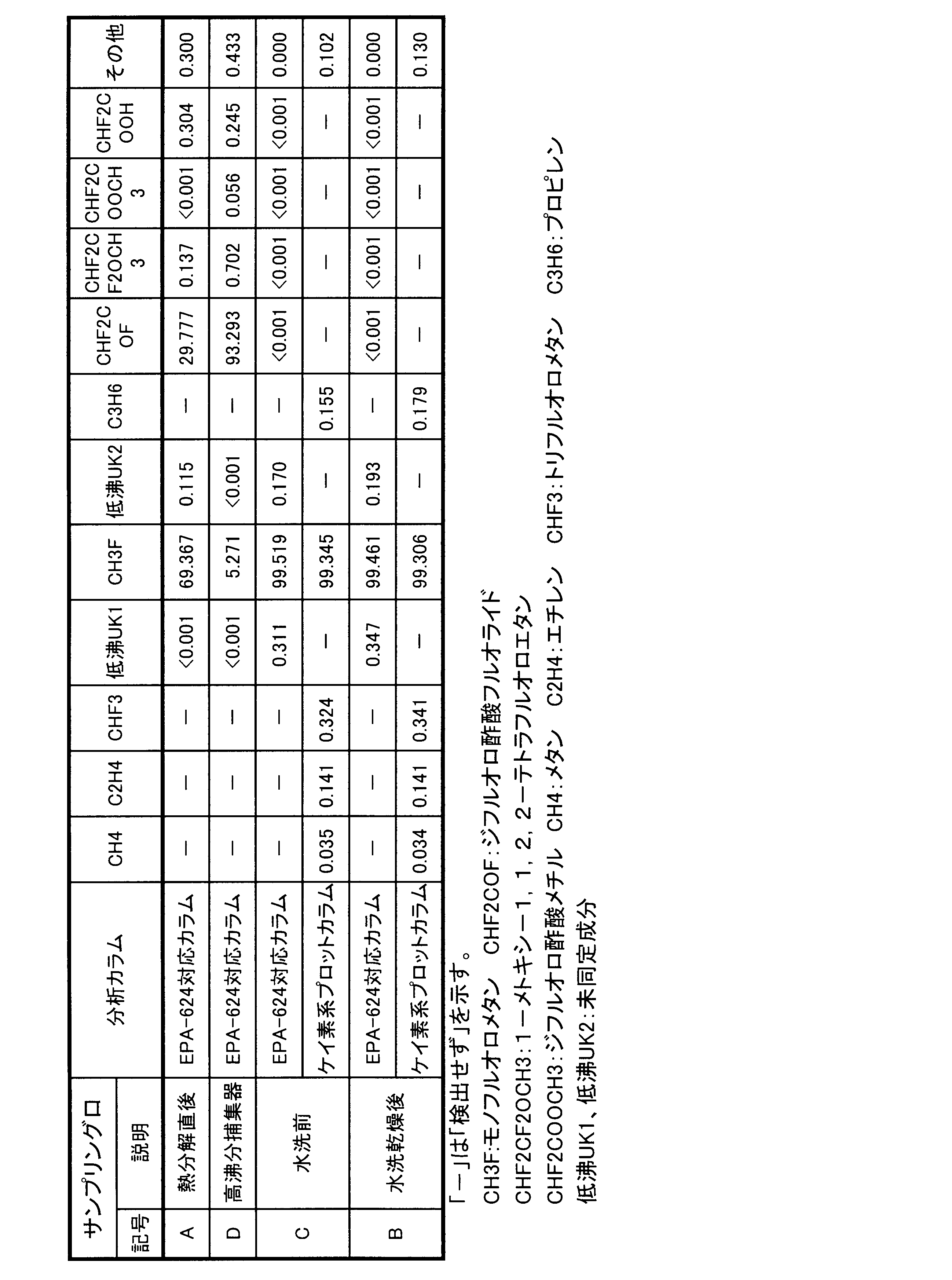
- a column corresponding to “EPA METHOD 624” was used for analysis of a composition containing high-polar difluoroacetic acid fluoride (CHF 2 COF) and the like (a composition collected at sampling port A).
- Compositions mainly containing low-boiling components such as methane (CH 3 F) and trifluoromethane (CHF 3 ) (compositions collected at the sampling port B) were analyzed using a silicon-based plot column.
- the HF supply rate is lowered to 1 g / min or less to suppress local heat generation, and after confirming that the temperature has reached the set temperature, gradually increase the HF
- the feed rate was returned to 4 g / min.
- the jacket set temperature was raised to 250 ° C. by 50 ° C., and the fluorination of ⁇ -alumina was repeated. Thereafter, the jacket set temperature was set to 300 ° C., and the HF flow rate was gradually increased to 20 g / min.
- the HF flow rate was lowered to 1 g / min.
- the fluorination treatment is further continued for 24 hours under the same conditions from the point when the heat spot is substantially not observed.
- Aldrich anhydrous aluminum fluoride (AlF 3 ) was tableted into 5 mm ⁇ ⁇ 5 mmL pellets and calcined at 700 ° C. for 5 hours in a nitrogen stream to prepare an aluminum fluoride catalyst.
- Example 1 The apparatus used for the experiment is shown in FIG.
- a stainless steel reaction tube 51 having an internal diameter of 37 mm and a length of 500 mm, which has a sampling port A53 on the outlet side and an electric furnace 52 on the outside, and a stainless steel Lieich ring filled with a stainless steel Raschig ring at the outlet of the reaction tube 51
- a jacketed high boiling point compound collector 55 having two cooling tubes 54 (circulating at ⁇ 50 ° C. refrigerant) (both circulating at ⁇ 50 ° C.
- a gas washing bottle A56 contents: Water, ice-cooled 59
- gas washing bottle B57 contents: 50% KOH aqueous solution, ice-cooled 59
- gas washing bottle C58 empty trap, ice-cooled 59
- soda lime and synthetic zeolite 4A are filled 1: 1.
- the dried pipes 60 were connected in series in this order, and a sampling port B61 was provided at the outlet of the dried pipe.
- the catalyst (230 cc) prepared in Catalyst Preparation Example 1 was charged into the reaction tube 51, and the electric furnace 52 was heated while flowing nitrogen at 15 cc / min.
- hydrogen fluoride (HF) was introduced through the vaporizer at 0.6 g / min. While circulating HF, the temperature was slowly raised to 210 ° C. and held for 15 hours.
- HFE-254pc 1-methoxy-1,1,2,2-tetrafluoroethane
- Examples 2 to 21 Using the catalysts prepared in Catalyst Preparation Examples 2 to 5, experiments were conducted in the same manner as in Example 1 under the conditions shown in Table 1. The obtained results are shown in Tables 1 and 2.
- Example 22 The apparatus used for the experiment is shown in FIG.
- the pyrolysis reaction was carried out under the same conditions as in Example 1, and the pyrolysis gas flowing out from the reaction tube 71 was passed through a serpentine tube 75 immersed in an ethanol bath maintained at ⁇ 15 ° C., and then the top of the tower was dry ice-acetone bath And cooled by a separation tower 78 (-15 ° C.) having a reflux condenser 79 maintained at ⁇ 78 ° C. to condense high-boiling components, and collected by a jacketed high-boiling compound collector 76 ( ⁇ 15 ° C.).
- the low-boiling components that do not condense were passed through an ice water trap 81, a potassium hydroxide aqueous solution trap 82, and a drying tube 83 filled with synthetic zeolite 4A.
- Samples were sampled from sampling port A73, sampling port B84, sampling port C80, and sampling port D77 shown in FIG. 4 and analyzed by gas chromatography using a column corresponding to “EPA METHOD 624”.
- Sampling port B84 and sampling port C80 were also analyzed by “silicon-based plot columns”, and it was confirmed that the analysis results substantially coincided between these columns. The results are shown in Table 3.
- Example 23 The apparatus shown in FIG. 4 was used.
- a stainless steel reaction tube 71 having an inner diameter of 37 mm and a length of 500 mm, having a sampling port A73 on the outlet side and having an electric furnace 72 on the outside, a polyethylene empty trap 74 at the outlet of the reaction tube 71, at ⁇ 15 ° C.
- a holding pipe 75 in the refrigerant bath maintained, a reflux condenser 79 maintained at -78 ° C.
- a separation tower 78 having B84 ( ⁇ 15 ° C.), an ice water trap 81, a basic aqueous solution trap 82 (50% KOH aqueous solution, ice-cooled), and a drying tube 83 filled with synthetic zeolite 4A 1: 1 are respectively made of fluororesin or polyethylene. It was connected with a pipe made of the product, and the outlet of the drying pipe 83 was opened to the abatement apparatus.
- the connection between the reaction tube 71 and the empty trap 74 was separated in the apparatus shown in FIG.
- the temperature of the electric furnace 72 was raised while flowing nitrogen at 15 cc / min.
- the supply rate was lowered to 0.1 g / min, and after confirming that the local heat generation had converged, gradually increased to 1.0 g / min.
- HF feed rate was increased.
- the temperature reached 350 ° C.
- the flow of HF was stopped after holding for 30 hours
- the nitrogen flow rate was increased to 200 cc / min
- the holding was continued for 2 hours
- the electric furnace temperature was lowered to 180 ° C.
- 1-methoxy-1,1, 2,2-Tetrafluoroethane (HFE-254pc) was introduced through the vaporizer at a rate of 0.2 g / min and immediately after the nitrogen flow was stopped.
- the setting of the electric furnace 72 was changed so that the reaction temperature became 150 ° C., and after reaching a steady state, the reaction tube outlet and the empty trap 74 were connected, and the apparatus configuration shown in FIG. 4 was restored.
- the effluent gas passes through an empty trap 74 and a serpentine tube 75, condenses high boiling point components in a separation tower 78 ( ⁇ 15 ° C.), and is collected in a jacketed high boiling point compound collector 76 ( ⁇ 15 ° C.).
- Low-boiling components that do not condense were passed through an ice water trap 81, a potassium hydroxide aqueous solution trap 82, and a drying tube 83.
- Example 24 The same experiment as in Example 23 was performed except that the reaction temperature was 175 ° C.
- the sample collected at the sampling port A73 was analyzed by a gas chromatograph of an FID detector (column corresponding to “EPA METHOD 624”), CH 3 F: 69.544%, CHF 2 COF: 28.240%, CHF 2 CF 2 OMe: 1.351%, other: 0.685%.
- the sample collected at the sampling port B84 was analyzed by a gas chromatograph (silicon-based plot column) of an FID detector, CH 4 : 0.024%, C 2 H 4 : 0.121%, CHF 3 : 0. 126%, CH 3 F: 99.455%, C 3 H 6 : 0.003%, and others: 0.271%.
- Example 25 A stainless steel reaction tube having an inner diameter of 23 mm and a length of 400 mm was filled with granular (particle size: about 2.5 to 3.5 mm) anhydrous calcium chloride (63 g, bulk: 120 cc) manufactured by Junsei Chemical Co., Ltd. Heated to 160 ° C. while flowing in minutes.
- organic matter CHF 2 COF: 94.181%, CHF 2 CF 2 OMe: 4.569% recovered in the jacketed high boiling point compound collector 76 in Example 24 was allowed to flow at a rate of 0.3 g / min. At the same time, the supply of nitrogen was stopped. An exotherm of 10 ° C. to 20 ° C.
- Example 26 The apparatus used for the experiment is shown in FIG.
- a refrigerant bath 94 maintained at ⁇ 30 ° C. at the outlet of the reaction tube 91, using a stainless steel reaction tube 91 having an inner diameter of 37 mm and a length of 500 mm, which has a sampling port A93 on the outlet side and an electric furnace 92 on the outside.
- Absorption tank A95 and absorption tank B96 were each charged with 170 g of toluene.
- the temperature of the electric furnace 92 was increased while flowing nitrogen at 15 cc / min.
- the supply rate is lowered to 0.1 g / min, and after confirming that the local heat generation has ended, gradually increase to 1.0 g / min.
- HF feed rate was increased.
- the flow of HF is stopped after holding for 20 hours, the flow rate of nitrogen is increased to 200 cc / min, the holding is continued for 2 hours, the electric furnace temperature is lowered to 190 ° C., and 1-methoxy-1,1, 2,2-Tetrafluoroethane (HFE-254pc) was introduced through the vaporizer at a rate of 0.10 g / min, and immediately after the nitrogen flow was stopped.
- HFE-254pc 1-methoxy-1,1, 2,2-Tetrafluoroethane
- the dried tube outlet gas was passed through a stainless steel cylinder cooled with liquid nitrogen to obtain 29 g of collected material.
- Table 2 shows the results of vaporizing the collected material and analyzing it with a silicon-based plot column. Furthermore, when this gas was analyzed by a gas chromatograph (column corresponding to “EPA METHOD 624”) of an FID detector, it was found that monofluoromethane was 87.02 area%, toluene was 12.70 area%, and other components were 0.28 area%. there were.
- Example 27 The apparatus used for the experiment is shown in FIG. A stainless steel reaction tube 101 having an inner diameter of 37 mm and a length of 500 mm, which has a sampling port A103 on the outlet side and an electric furnace 102 provided outside, is provided in a refrigerant bath maintained at ⁇ 30 ° C. at the outlet of the reaction tube 101.
- Absorption tank A105 and absorption tank B106 were each charged with 200 cc of ethanol.
- the temperature of the electric furnace 102 was raised while flowing nitrogen at 15 cc / min.
- the supply rate is lowered to 0.1 g / min, and after confirming that the local heat generation has ended, gradually increase to 1.0 g / min.
- HF feed rate was increased.
- the flow of HF is stopped after holding for 20 hours, the flow rate of nitrogen is increased to 200 cc / min, the holding is continued for 2 hours, the electric furnace temperature is lowered to 190 ° C., and 1-methoxy-1,1, 2,2-Tetrafluoroethane (HFE-254pc) was introduced through the vaporizer at a rate of 0.10 g / min, and immediately after the nitrogen flow was stopped.
- HFE-254pc 1-methoxy-1,1, 2,2-Tetrafluoroethane
- Example 28 The same experiment as in Example 27 was performed except that 20% KOH aqueous solution (200 cc each) was used instead of ethanol in absorption tank A105 and absorption tank B106, the cooling temperature was -2 ° C, and the cleaning tank 107 was an empty trap. It was.
- the analysis results are shown in Tables 1 and 2. Further, when the gas collected at the sampling port B109 was analyzed by a gas chromatograph (“EPA METHOD 624” compatible column) of an FID detector, it was 99.84 area% monofluoromethane and 0.16 area% other components. It was.
- FIG. 1A schematically shows a cross-sectional schematic diagram of the sample before etching
- FIG. 1B schematically shows a cross-sectional schematic diagram of the sample after etching.
- An SiO 2 interlayer insulating film 22 was formed on the single crystal silicon wafer 21, and a resist mask 23 having an opening as an etching mask was formed on the SiO 2 film.
- reference numeral 24 represents a shoulder drop.
- FIG. 2 shows a schematic cross-sectional view of the remote plasma apparatus used in the experiment.
- the substrate (sample holder 11) temperature was 25 ° C.
- the pressure was 2.67 Pa (0.02 torr)
- the RF power density was set to 2.2 W / cm 2 .
- the relative etching rate is obtained when the area of SiF 3 (mass number 85) obtained by analyzing the exhaust gas of the reaction chamber 1 with a mass analyzer (MS) is used (monofluoromethane). each was determined as 1.000 and the area ratio of the area of SiF 3 use example 2), the relative etch rate of monofluoromethane prepared in example 20 and example 23, 1.002 and 1.001 Met. The results are shown in Table 4.
- Monofluoromethane obtained by the method of the present invention is useful as a semiconductor gas (dry etching agent, cleaning agent), and by-product difluoroacetic acid fluoride and derivatives thereof are catalysts for various reactions, intermediates for medicines and agricultural chemicals, and functions. It is a useful compound used for an intermediate of a functional material.
Landscapes
- Chemical & Material Sciences (AREA)
- Organic Chemistry (AREA)
- Chemical Kinetics & Catalysis (AREA)
- Engineering & Computer Science (AREA)
- Oil, Petroleum & Natural Gas (AREA)
- Organic Low-Molecular-Weight Compounds And Preparation Thereof (AREA)
Abstract
Description
1-メトキシ-1,1,2,2-テトラフルオロエタンを触媒と接触させて熱分解する熱分解工程と、熱分解生成物からモノフルオロメタンを回収する工程とを少なくとも有するモノフルオロメタンの製造方法。
モノフルオロメタンを回収する工程が、熱分解生成物の一部を液化してモノフルオロメタンを分離する工程を含む工程である発明1。
熱分解生成物の一部の液化を、冷却することで行う発明2。
冷却温度が、-80~-5℃である発明3。
モノフルオロメタンを回収する工程が、ジフルオロ酢酸フルオライドに対して不活性な溶媒にジフルオロ酢酸フルオライドを吸収させる工程を含む工程である発明1。
ジフルオロ酢酸フルオライドに対して不活性な溶媒が、炭化水素化合物である発明5。
モノフルオロメタンを回収する工程が、ジフルオロ酢酸フルオライドに対して活性な化合物と接触させる工程を含む工程である発明1。
ジフルオロ酢酸フルオライドに対して活性な化合物が、水、アルコール類、第一アミン、第二アミンまたはαβ不飽和カルボン酸エステルである発明7。
ジフルオロ酢酸フルオライドに対して活性な化合物と接触させる工程において、溶媒を存在させる発明7または8。
ジフルオロ酢酸フルオライドに対して活性な化合物と接触させる工程において、塩基性物質を存在させる発明7~9。
熱分解工程が、金属酸化物、部分フッ素化金属酸化物、金属フッ化物、未処理もくしはフッ素化処理したリン酸または未処理もくしはフッ素化処理したリン酸塩を触媒とし、熱分解温度を100℃~400℃とする発明1~10。
熱分解工程が、アルミナ、部分フッ素化アルミナまたはフッ化アルミニウムを触媒とし、熱分解温度を130℃~260℃とする発明1~10。
請求項1~12のいずれか1項に記載の方法で製造されたモノフルオロメタンを含むことを特徴とする半導体装置製造工程におけるエッチング剤またはクリーニングガス。
請求項1~12のいずれか1項に記載の方法で製造されたモノフルオロメタンを用いることを特徴とする半導体装置製造工程におけるエッチング方法またはクリーニング方法
モノフルオロメタンを得ると共にジフルオロ酢酸フルオライドを分離して得る工程を有する発明1~6。
CHF2CF2OCH3 → CH3F + CHF2COF
目的化合物であるモノフルオロメタン(沸点:-78℃)は、その他の主な成分であるジフルオロ酢酸フルオライド(沸点:0℃)および未反応のHFE-254pc(沸点:40℃)との沸点差が大きく、熱分解装置から流出した熱分解生成物(ガス)を冷却すると、単純な冷却液化によって容易にモノフルオロメタンを主とする成分を分離して回収することができる。当然、熱分解生成物を加圧して液化することもでき、その場合でも冷却することが好ましい。このとき、一部の成分が液化して、低沸点成分としてのモノフルオロメタンを主とする組成物と、高沸点成分としてのジフルオロ酢酸フルオライドまたはジフルオロ酢酸フルオライドとHFE-254pcの混合物に容易に分離できる。組成は冷却温度により任意に変動させることができるが、通常、低沸点成分には、不純物としてCH4、C2H4、CHF3、C3H6等が含まれることがあり、高沸点成分には同様にCHF2COOCH3、CHF2COOH等が含まれることがある。
熱分解により生成した熱分解生成物をジフルオロ酢酸フルオライドと反応しない不活性な溶媒(以後、「不活性溶媒」という。)と接触させて、熱分解生成物に含まれるジフルオロ酢酸フルオライドを溶媒に吸収させ、非溶解のモノフルオロメタンを取り出すことができる。
反応分離法では、熱分解により生じた反応生成物に含まれるジフルオロ酢酸フルオライドを反応により高沸点で安定な化合物に変換してからモノフルオロメタンから分離する。変換と分離を同一の容器で同時に行うこともでき、異なる容器で行うこともできる。反応相手(反応試剤)となる活性な化合物としては、水、アルコール類または第一アミンもしくは第二アミン、αβ不飽和カルボン酸エステルなどの活性な水素原子を有する化合物が挙げられるがこれらに限られない。これらのうち、水またはアルコール類が好ましい。これらの化合物の反応は、次の式で例示できる。
CHF2COF + ROH → CHF2COOR + HF
CHF2COF + RNH2 → CHF2CONRH + HF
CHF2COF + R2NH → CHF2CONR2 + HF
前記各種の分離方法で得られた低沸点成分は、微量の酸性成分を含むことがある。例えば、冷却液化による分離後の低沸点成分には飛沫同伴等によりジフルオロ酢酸フルオライドまたはフッ化水素が混入することがある。低沸点成分に含まれる酸性成分は水および/または塩基性水溶液と接触させて洗浄した後、乾燥処理することによって取り除くことができ、高純度のモノフルオロメタンとすることができる。洗浄方法は、気泡塔などを用いるバブリング方式、充填塔を用いるスクラバー方式など、「吸収分離法」において示した各種の気-液接触方法を任意に適用できる。塩基性水溶液としては、KOH水溶液、NaOH水溶液、Ca(OH)2水溶液等が例示されるが、接触させた際に生成するフッ化物塩の飽和溶解度が高く、装置の閉塞等のトラブルを起こし難いKOH水溶液が好ましい。洗浄後は、ソーダライム、合成ゼオライト、シリカゲル等の脱水剤によって、水分を除去することが望ましい。また、ソーダライムや合成ゼオライト、シリカゲルは脱水だけでなく、好ましくない副生物を除去する効果を有することもある。合成ゼオライトとしては、3A型、4A型、5A型、10X型、13X型などが使用できる。熱分解で得られたモノフルオロメタンを洗浄および、ゼオライト、ソーダライム等で乾燥する工程のみで、精密蒸留精製をしないで、純度を容易に99%以上とすることができ、最適条件で熱分解した場合、純度を99.9%以上とすることができる。これは、半導体工業におけるエッチングガスやクリーニングガスとして使用するのに十分な純度である。
モノフルオロメタンは、半導体工業を中心とした薄膜デバイス製造プロセス、光デバイス製造プロセス、超鋼材料製造プロセスなどにおいて、CVD法、スパッタリング法、ゾルゲル法、蒸着法などを用いて作成される薄膜、厚膜をエッチングする所謂エッチングガス(エッチング剤)として有用である。また、これらのプロセスにおいて薄膜等の作成時に装置、配管等へ堆積した薄膜や粉体を除去するための所謂クリーニングガスとしても有用である。
85%リン酸(H3PO4) 30gを300ccの水で希釈したリン酸水溶液へ日本エンバイロケミカルズ株式会社製の粒状活性炭G2X 100gを浸漬し、よく攪拌した後3日間静置した。その後、ロータリーエバポレーターで乾燥し、次いで、電気炉で窒素気流中、350℃で5時間焼成して、リン酸担持活性炭触媒を調製した。
硝酸アルミニウム9水塩(Al(NO3)3・9H2O) 1000g(2.666mol)と硝酸セリウム6水塩(Ce(NO3)3・6H2O) 128.6g(0.296mol)を5300ccの純水で溶かし、さらに85%リン酸306g(3.12mol)を加えて攪拌した。この状態で、透明な溶液であった。これに1Lの大型滴下ロートにより10%アンモニア水(約3000cc)を約10時間かけて滴下して塩基性にした。固形分濃度が高く、滴下途中から攪拌機では攪拌不能となったので、ステンレス鋼製のスコップで手攪拌した。生成した白色沈殿物を、一晩静置し、吸引濾過し、5回水洗浄を行った。
この白色固体を、ステンレス鋼製パッドに移し、180℃の乾燥機で一晩乾燥した。乳鉢ですりつぶし、篩い分けし、打錠器にて5mmφ×5mmLのペレットに成形し、窒素気流中700℃で5時間焼成して、リン酸アルミニウム・リン酸セリウム触媒を調製した。
アルドリッチ製リン酸アルミニウム(Aluminum phosphate)を5mmφ×5mmLのペレットに打錠成形し、窒素気流中700℃で5時間焼成して、リン酸アルミニウム触媒を調製した。
マントルヒーターを備えた長さ1.5m×内径55mmのステンレス鋼(SUS316)製反応管にγ-アルミナビーズ(住友化学、KHS-46)を2kg充填した。マントルヒーター温度を50℃に制御し、窒素(1000cc/分)を流通させながら、気化器で気化させたフッ化水素(HF)を4g/分で流通させた。この流通によって、特に入り口部に発熱(吸着熱および反応熱)が観測され、その発熱帯は徐々に出口方向に移動した。この時、温度が最も高いヒートスポットが300℃を超えた場合、HF供給速度を1g/分以下に下げて、局所発熱を抑制し、温度が設定温度になったことを確認後、徐々にHF供給速度を4g/分まで戻した。発熱帯が出口付近に達した後、ジャケット設定温度を50℃ずつ250℃まで上げて、前記のγ-アルミナのフッ素化を繰り返した。その後、ジャケット設定温度を300℃に設定し、HF流量を徐々に20g/分まで上げた。この時のヒートスポットの温度が350℃を超えた場合は、HF流量を1g/分に下げた。ジャケット温度300℃、HF流量20g/分の条件で、実質的にヒートスポットが観測されなくなった時点から、さらに同じ条件で24時間フッ素化処理を継続し、その後、窒素だけを流通させながら、ヒーターの電源を切り、冷却し、フッ素化処理したアルミナ触媒を得た。
アルドリッチ製無水フッ化アルミニウム(AlF3)を5mmφ×5mmLのペレットに打錠成形し、窒素気流中700℃で5時間焼成して、フッ化アルミニウム触媒を調製した。
モノフルオロメタンとジフルオロ酢酸フルオライドの標品を用いて、FID検出器の感度測定を行った。モノフルオロメタン (40kPa,300torr)およびジフルオロ酢酸フルオライド (40kPa、300torr)をシリンダー(300cc)に採取し(モル比:1:1、全圧:80kPa、600torr)、シリンダーを25℃に加温して、これからガスシリンジに0.2ccの試料を取り、「EPA METHOD 624」対応カラムを使用して、ガスクロマトグラフ分析を行い、面積比を求めた。
CH3Fの面積:CHF2COFの面積=2.41:1.00。
実験に用いた装置を図3に示す。出口側にサンプリング口A53を有し外部に電気炉52を備えた内径37mm、長さ500mmのステンレス鋼製反応管51を用い、反応管51の出口にステンレス鋼製ラシヒリングを充填したステンレス鋼製リービッヒ冷却管54(-50℃の冷媒を流通)を2本有するジャケット付高沸点化合物捕集器55(何れも-50℃の冷媒を流通)を接続し、さらに、ガス洗浄瓶A56(内容物:水、氷冷59)、ガス洗浄瓶B57(内容物:50%KOH水溶液、氷冷59)、ガス洗浄瓶C58(空トラップ、氷冷59)、ソーダライムと合成ゼオライト4Aを1:1で充填した乾燥管60をこの順に直列に接続し、乾燥管の出口にサンプリング口B61を設けた。


触媒の調製例2~5で調製した触媒を用いて、表1記載の条件で、実施例1と同様に実験した。得られた結果を表1および表2に示す。
実験に用いた装置を図4に示す。熱分解反応を実施例1と同一の条件で行い、反応管71から流出した熱分解ガスを-15℃に保ったエタノール浴に浸した蛇管75に通じた後、塔頂をドライアイス-アセトン浴で-78℃に保った還流冷却器79を有する分離塔78(-15℃)で冷却し、高沸点成分を凝縮させ、ジャケット付高沸点化合物捕集器76(-15℃)で捕集し、凝縮しない低沸点成分を氷水トラップ81、水酸化カリウム水溶液トラップ82、合成ゼオライト4Aを充填した乾燥管83に通じた。図4に示すサンプリング口A73、サンプリング口B84、サンプリング口C80、サンプリング口D77から試料をサンプリングして、「EPA METHOD 624」対応カラムを用いてガスクロマトグラフ分析した。サンプリング口B84、サンプリング口C80については、「ケイ素系プロットカラム」でも分析して、分析結果がこれらのカラムの間で実質的に一致することを確認した。結果を表3に示す。
外部に電気炉を備えた内径23mm、長さ500mmのステンレス鋼製反応管に日本エンバイロケミカルズ株式会社製の粒状活性炭G2X(50cc)を仕込み、窒素を15cc/分で流しながら電気炉で加熱した。反応管内部の温度が200℃に達した時に、原料である1-メトキシ-1,1,2,2-テトラフルオロエタン(HFE-254pc)を0.4g/分の速度で、気化器を通して導入した。反応管内部の温度が250℃で定常状態になったときに、生成ガスを分析した結果、転化率0.9%であり、実質的に原料が回収された。
反応管内部の温度を300℃とする以外、参考例2と同様にして反応を行った結果、転化率:2.6%であった。温度を300℃まで上げたが、同様に原料回収であった。
外部に電気炉を備えた内径23mm、長さ500mmのステンレス鋼製反応管に日本エンバイロケミカルズ株式会社製の粒状活性炭G2X(50cc)を仕込み、窒素を15cc/分で流しながら電気炉で加熱した。反応管内部の温度が50℃に達した時に、HF(0.6g/分)を、気化器を通して導入した。HFを流通させたまま、300℃までゆっくりと昇温し、5時間保持した。HFの流通を止め、窒素流量を200cc/分に増やして2時間保持後、窒素流量を15cc/分に変更し、1-メトキシ-1,1,2,2-テトラフルオロエタン(HFE-254pc)を0.4g/分の速度で、気化器を通して導入した。反応管内部の温度300℃で定常状態になったときに、生成ガスを分析した結果、転化率:2.8%で、実質的に原料回収であり、リン酸を担持していない活性炭にHF処理を行っても、効果が認められなかった。
図4に示す装置を用いた。出口側にサンプリング口A73を有し外部に電気炉72を備えた内径37mm、長さ500mmのステンレス鋼製反応管71を用い、反応管71の出口にポリエチレン製の空トラップ74、-15℃に保たれた冷媒浴中の蛇管75、塔頂にドライアイス-アセトン浴で-78℃に保った還流冷却器79と塔底にジャケット付高沸点化合物捕集器76を有し出口側にサンプリング口B84を有する分離塔78(-15℃)、氷水トラップ81、塩基性水溶液トラップ82(50%KOH水溶液、氷冷)、合成ゼオライト4Aを1:1で充填した乾燥管83をそれぞれフッ素樹脂またはポリエチレン製の配管で接続し、乾燥管83の出口は除害装置に開放した。
反応温度を175℃にする以外、実施例23と同様の実験を行った。サンプリング口A73で採取したサンプルをFID検出器のガスクロマトグラフ(「EPA METHOD 624」対応カラム)で分析したところ、CH3F:69.544%、CHF2COF:28.240%、CHF2CF2OMe:1.351%、その他:0.685%であった。また、サンプリング口B84で捕集したサンプルをFID検出器のガスクロマトグラフ(ケイ素系プロットカラム)で分析したところ、CH4:0.024%、C2H4:0.121%、CHF3:0.126%、CH3F:99.455%、C3H6:0.003%、その他:0.271%であった。結果を表1および表2に示す。
内径23mm長さ400mmのステンレス鋼製反応管に粒状(粒径約2.5~3.5mm)の純正化学株式会社製無水塩化カルシウム(63g、かさ:120cc)を充填して、窒素を50cc/分で流しながら160℃に加熱した。実施例24でジャケット付高沸点化合物捕集器76に回収された有機物(CHF2COF:94.181%、CHF2CF2OMe:4.569%)を0.3g/分の速度で流すと同時に、窒素の供給を止めた。入り口付近で10℃~20℃の発熱がみられ、経時的にそのヒートスポットが出口の方に移動した。有機物を77.9g供給した時に出口ガスをFID検出器のガスクロマトグラフ(「EPA METHOD 624」対応カラム)で分析したところ、CHF2COF:1.105%、CH3Cl:4.708%、CHF2CF2OMe:0.001%、CHF2COCl:93.769%、その他:0.417%であった。
HFE-254pcの代わりに、実施例23でジャケット付高沸点化合物捕集器76に回収された有機物を蒸留して得られた純度98.2%のCHF2COF(主な不純物 CHF2CF2OMe:1.1%)を供給した以外、実施例23と同じ実験を行った。サンプリング口A73で採取したサンプルをFID検出器のガスクロマトグラフ(「EPA METHOD 624」対応カラム)で分析したところ、CHF3:83.988%、CH3F:検出されず、CHF2COF:検出されず、CHF2CF2OMe:検出されず、その他:16.012%であった。また、サンプリング口B84で捕集したサンプルをFID検出器のガスクロマトグラフ(ケイ素系プロットカラム)で分析したところ、CH4:0.368%、C2H4:0.238%、CHF3:92.653%、CH3F:0.569%、C3H6:0.176%、CHF2CF2OMe:検出されず、その他:5.996%であった。
反応温度を330℃にする以外、実施例23と同じ実験を行った。サンプリング口A73で採取したサンプルをFID検出器のガスクロマトグラフ(「EPA METHOD 624」対応カラム)で分析したところ、CH3F:26.013%、CHF2COF:9.215%、CHF2CF2OMe:検出されず(検出限界(0.001%)未満)、その他:64.772%であった。また、サンプリング口B84で捕集したサンプルをFID検出器のガスクロマトグラフ(ケイ素系プロットカラム)で分析したところ、CH4:9.876%、C2H4:19.854%、CHF3:28.812%、CH3F:26.187%、C3H6:4.877%、CHF2CF2OMe:検出されず、その他:10.397%であった。結果を表1および表2に示す。
実験に用いた装置を図5に示す。出口側にサンプリング口A93を有し外部に電気炉92を備えた内径37mm、長さ500mmのステンレス鋼製反応管91を用い、反応管91の出口に-30℃に保たれた冷媒浴94中に浸したステンレス鋼製の吸収槽A95、吸収槽B96およびフッ素樹脂製の300ccの空トラップ97並びに300cccのソーダライムを充填し、出口側にサンプリング口B99を備えたステンレス鋼製乾燥管98をこの順にフッ素樹脂またはポリエチレン製の配管で接続し、乾燥管98の出口を除害装置に開放した。吸収槽A95および吸収槽B96にはそれぞれトルエン170gを仕込んだ。
実験に用いた装置を図6に示す。出口側にサンプリング口A103を有し外部に電気炉102を備えた内径37mm、長さ500mmのステンレス鋼製反応管101を設け、反応管101の出口に-30℃に保たれた冷媒浴中に浸したステンレス鋼製の吸収槽A105と吸収槽B106、200ccの水を仕込んだ洗浄槽(水トラップ)107および300cccのソーダライムを充填し、出口側にサンプリング口B109を備えたステンレス鋼製乾燥管108をこの順にフッ素樹脂またはポリエチレン製の配管で接続し、乾燥管108の出口を除害装置に開放した。吸収槽A105および吸収槽B106にはそれぞれエタノール200ccを仕込んだ。
吸収槽A105、吸収槽B106にエタノールの代わりに20%KOH水溶液(各200cc)を仕込み、冷却温度を-2℃とし、洗浄槽107を空トラップとした以外、実施例27と同様の実験を行った。分析結果を表1および表2に示した。さらに、サンプリング口B109で採取したガスをFID検出器のガスクロマトグラフ(「EPA METHOD 624」対応カラム)で分析したところ、モノフルオロメタン99.84面積%で、その他成分が0.16面積%であった。
実施例20および実施例23で得られた精製・乾燥後のモノフルオロメタンを液体窒素で冷却してステンレス鋼製シリンダーへ捕集した。捕集物について液体窒素による凝固、真空ポンプによる減圧、融解(室温)からなる脱ガス操作を3回繰り返し、空気成分を除去した。このガスをコンタクトホール加工に使用し、層間絶縁膜(SiO2)をエッチングした例を示す。図1Aにエッチング前の試料の断面模式図を模式的に示し、図1Bにエッチング後の試料の断面模式図を模式的に示す。単結晶シリコンウエハ21上にSiO2層間絶縁膜22を形成し、そのSiO2膜の上にエッチングマスクとして開口部を設けたレジスト・マスク23を形成した。図1Bにおいて、参照番号24は肩落ち部を表す。

市販の半導体グレード(製品の試験成績票における純分値:99.99%)のモノフルオロメタンを用いて[モノフルオロメタンの使用例1]と同じ条件でエッチング試験を行った。その結果を表4に示す。
21:シリコンウエハ 22: SiO2層間絶縁膜 23:レジスト・マスク 24:肩落ち部
51:反応管 52:電気炉 53:サンプリング口A 54:リービッヒ冷却管 55:ジャケット付高沸点化合物捕集器 56:水トラップ 57:塩基性水溶液トラップ 58:空トラップ 59:氷浴 60:ソーダライム管 61:サンプリング口B
71:反応管 72:電気炉 73:サンプリング口A 74:空トラップ 75:蛇管 76:ジャケット付高沸点化合物捕集器 77:サンプリング口D 78:分離塔 79:還流冷却器 80:サンプリング口C 81:氷水トラップ 82:塩基性水溶液トラップ 83:乾燥管 84:サンプリング口B
91:反応管 92:電気炉 93:サンプリング口A 94:冷媒浴 95:吸収槽A 96:吸収槽B 97:空トラップ 98:乾燥管 99:サンプリング口B
101:反応管 102:電気炉 103:サンプリング口A 104:冷媒浴 105:吸収槽A 106:吸収槽B 107:水トラップ 108:乾燥管 109:サンプリング口B
Claims (15)
- 1-メトキシ-1,1,2,2-テトラフルオロエタンを触媒と接触させて熱分解する熱分解工程と、熱分解生成物からモノフルオロメタンを回収する工程とを少なくとも有するモノフルオロメタンの製造方法。
- モノフルオロメタンを回収する工程が、熱分解生成物の一部を液化してモノフルオロメタンを分離する工程を含む工程である請求項1に記載のモノフルオロメタンの製造方法。
- 熱分解生成物の一部の液化を、冷却することで行う請求項2に記載のモノフルオロメタンの製造方法。
- 冷却温度が、-80~-5℃である請求項3に記載のモノフルオロメタンの製造方法。
- モノフルオロメタンを回収する工程が、ジフルオロ酢酸フルオライドに対して不活性な溶媒にジフルオロ酢酸フルオライドを吸収させる工程を含む工程である請求項1に記載のモノフルオロメタンの製造方法。
- ジフルオロ酢酸フルオライドに対して不活性な溶媒が、炭化水素化合物である請求項5に記載のモノフルオロメタンの製造方法。
- モノフルオロメタンを回収する工程が、ジフルオロ酢酸フルオライドに対して活性な化合物と接触させる工程を含む工程である請求項1に記載のモノフルオロメタンの製造方法。
- ジフルオロ酢酸フルオライドに対して活性な化合物が、水、アルコール類、第一アミン、第二アミンまたはαβ不飽和カルボン酸エステルである請求項7に記載のモノフルオロメタンの製造方法。
- ジフルオロ酢酸フルオライドに対して活性な化合物と接触させる工程において、溶媒を存在させる請求項7または請求項8に記載のモノフルオロメタンの製造方法。
- ジフルオロ酢酸フルオライドに対して活性な化合物と接触させる工程において、塩基性物質を存在させる請求項7~9のいずれか1項に記載のモノフルオロメタンの製造方法。
- 熱分解工程が、金属酸化物、部分フッ素化金属酸化物、金属フッ化物、未処理もくしはフッ素化処理したリン酸または未処理もくしはフッ素化処理したリン酸塩を触媒とし、熱分解温度を100℃~400℃とする請求項1~10のいずれか1項に記載のモノフルオロメタンの製造方法。
- 熱分解工程が、アルミナ、部分フッ素化アルミナまたはフッ化アルミニウムを触媒とし、熱分解温度を130℃~260℃とする請求項1~10のいずれか1項に記載のモノフルオロメタンの製造方法。
- 請求項1~12のいずれか1項に記載の方法で製造されたモノフルオロメタンを含むことを特徴とする半導体装置製造工程におけるエッチング剤またはクリーニングガス。
- 請求項1~12のいずれか1項に記載の方法で製造されたモノフルオロメタンを用いることを特徴とする半導体装置製造工程におけるエッチング方法またはクリーニング方法
- モノフルオロメタンを得ると共にジフルオロ酢酸フルオライドを分離して得る工程を有する請求項1~6のいずれか1項に記載のモノフルオロメタンの製造方法。
Priority Applications (1)
| Application Number | Priority Date | Filing Date | Title |
|---|---|---|---|
| CN201180009940.1A CN102762525B (zh) | 2010-02-17 | 2011-02-09 | 半导体气体的制造方法 |
Applications Claiming Priority (4)
| Application Number | Priority Date | Filing Date | Title |
|---|---|---|---|
| JP2010-032525 | 2010-02-17 | ||
| JP2010032525 | 2010-02-17 | ||
| JP2010143716 | 2010-06-24 | ||
| JP2010-143716 | 2010-06-24 |
Publications (1)
| Publication Number | Publication Date |
|---|---|
| WO2011102268A1 true WO2011102268A1 (ja) | 2011-08-25 |
Family
ID=44482855
Family Applications (1)
| Application Number | Title | Priority Date | Filing Date |
|---|---|---|---|
| PCT/JP2011/052702 Ceased WO2011102268A1 (ja) | 2010-02-17 | 2011-02-09 | 半導体ガスの製造方法 |
Country Status (2)
| Country | Link |
|---|---|
| CN (1) | CN102762525B (ja) |
| WO (1) | WO2011102268A1 (ja) |
Cited By (8)
| Publication number | Priority date | Publication date | Assignee | Title |
|---|---|---|---|---|
| WO2012077561A1 (ja) * | 2010-12-09 | 2012-06-14 | セントラル硝子株式会社 | 精製モノフルオロメタンの製造方法 |
| WO2014077246A1 (ja) * | 2012-11-14 | 2014-05-22 | ダイキン工業株式会社 | ドライエッチングガスの製造方法 |
| KR20160027984A (ko) | 2013-08-09 | 2016-03-10 | 다이킨 고교 가부시키가이샤 | 불화메탄의 제조 방법 |
| JP5900575B1 (ja) * | 2014-10-23 | 2016-04-06 | ダイキン工業株式会社 | フッ化メタンの製造方法 |
| JP2016084293A (ja) * | 2014-10-23 | 2016-05-19 | ダイキン工業株式会社 | フッ化メタンの製造方法 |
| JP2016141674A (ja) * | 2015-02-05 | 2016-08-08 | ダイキン工業株式会社 | フッ化メチルの製造方法 |
| JP2023141869A (ja) * | 2022-03-24 | 2023-10-05 | 東京エレクトロン株式会社 | エッチング方法及びプラズマ処理システム |
| CN118925254A (zh) * | 2024-07-24 | 2024-11-12 | 东营银桥化工有限责任公司 | 一种二氯乙酰氯提纯系统 |
Families Citing this family (5)
| Publication number | Priority date | Publication date | Assignee | Title |
|---|---|---|---|---|
| JP6372423B2 (ja) * | 2015-06-03 | 2018-08-15 | ダイキン工業株式会社 | フッ化メタンを含む組成物及びその製造方法 |
| CN107867997B (zh) * | 2016-09-28 | 2023-07-04 | 中化近代环保化工(西安)有限公司 | 一种制备二氟乙酰氟的方法 |
| CN106831406B (zh) * | 2017-02-14 | 2019-10-11 | 中国科学院上海高等研究院 | 一种非金属催化制备二氟乙酰氟的方法及装置 |
| CN114149318B (zh) * | 2021-10-28 | 2024-11-05 | 浙江诺亚氟化工有限公司 | 一种低分子量全氟聚醚废料在高温下氧化裂解合成小分子量酰氟的方法 |
| CN114085142B (zh) * | 2021-10-28 | 2024-08-20 | 浙江诺亚氟化工有限公司 | 一种含氟醚类化合物气相氧化裂解反应合成酰氟类化合物的方法 |
Citations (6)
| Publication number | Priority date | Publication date | Assignee | Title |
|---|---|---|---|---|
| JPS5640617A (en) * | 1979-08-31 | 1981-04-16 | Du Pont | Synthesis of fluorocarbonyl compound |
| JPS60116637A (ja) * | 1983-11-29 | 1985-06-24 | Showa Denko Kk | フルオロメタンの製造方法 |
| JPH0892162A (ja) * | 1994-07-28 | 1996-04-09 | Asahi Glass Co Ltd | ジフルオロ酢酸フルオリドおよびジフルオロ酢酸エステルの製造方法 |
| WO2005026090A1 (ja) * | 2003-09-10 | 2005-03-24 | Showa Denko K.K. | ハイドロフルオロカーボンの製造方法、その製品およびその用途 |
| WO2010055807A1 (ja) * | 2008-11-12 | 2010-05-20 | セントラル硝子株式会社 | ジフルオロ酢酸エステルの製造方法 |
| WO2010098220A1 (ja) * | 2009-02-27 | 2010-09-02 | セントラル硝子株式会社 | ジフルオロメチルカルボニル化合物の製造方法 |
-
2011
- 2011-02-09 WO PCT/JP2011/052702 patent/WO2011102268A1/ja not_active Ceased
- 2011-02-09 CN CN201180009940.1A patent/CN102762525B/zh not_active Expired - Fee Related
Patent Citations (6)
| Publication number | Priority date | Publication date | Assignee | Title |
|---|---|---|---|---|
| JPS5640617A (en) * | 1979-08-31 | 1981-04-16 | Du Pont | Synthesis of fluorocarbonyl compound |
| JPS60116637A (ja) * | 1983-11-29 | 1985-06-24 | Showa Denko Kk | フルオロメタンの製造方法 |
| JPH0892162A (ja) * | 1994-07-28 | 1996-04-09 | Asahi Glass Co Ltd | ジフルオロ酢酸フルオリドおよびジフルオロ酢酸エステルの製造方法 |
| WO2005026090A1 (ja) * | 2003-09-10 | 2005-03-24 | Showa Denko K.K. | ハイドロフルオロカーボンの製造方法、その製品およびその用途 |
| WO2010055807A1 (ja) * | 2008-11-12 | 2010-05-20 | セントラル硝子株式会社 | ジフルオロ酢酸エステルの製造方法 |
| WO2010098220A1 (ja) * | 2009-02-27 | 2010-09-02 | セントラル硝子株式会社 | ジフルオロメチルカルボニル化合物の製造方法 |
Non-Patent Citations (1)
| Title |
|---|
| DAVID C. ENGLAND: "Catalytic Conversion of Fluoroalkyl Alkyl Ethers to Carbonyl Compounds", JOURNAL OF ORGANIC CHEMISTRY, vol. 49, no. 21, 1984, pages 4007 - 4008 * |
Cited By (21)
| Publication number | Priority date | Publication date | Assignee | Title |
|---|---|---|---|---|
| WO2012077561A1 (ja) * | 2010-12-09 | 2012-06-14 | セントラル硝子株式会社 | 精製モノフルオロメタンの製造方法 |
| JP2012121855A (ja) * | 2010-12-09 | 2012-06-28 | Central Glass Co Ltd | 半導体ガスの製造方法 |
| US10011553B2 (en) | 2012-11-14 | 2018-07-03 | Daikin Industries, Ltd. | Method for producing dry etching gas |
| KR20170010104A (ko) | 2012-11-14 | 2017-01-25 | 다이킨 고교 가부시키가이샤 | 드라이 에칭 가스의 제조 방법 |
| WO2014077246A1 (ja) * | 2012-11-14 | 2014-05-22 | ダイキン工業株式会社 | ドライエッチングガスの製造方法 |
| JP2014114277A (ja) * | 2012-11-14 | 2014-06-26 | Daikin Ind Ltd | ドライエッチングガスの製造方法 |
| KR20160027984A (ko) | 2013-08-09 | 2016-03-10 | 다이킨 고교 가부시키가이샤 | 불화메탄의 제조 방법 |
| US9919990B2 (en) | 2013-08-09 | 2018-03-20 | Daikin Industries, Ltd. | Method for manufacturing methyl fluoride |
| JP2016084293A (ja) * | 2014-10-23 | 2016-05-19 | ダイキン工業株式会社 | フッ化メタンの製造方法 |
| KR20170070190A (ko) | 2014-10-23 | 2017-06-21 | 다이킨 고교 가부시키가이샤 | 불화메탄의 제조 방법 |
| WO2016063939A1 (ja) * | 2014-10-23 | 2016-04-28 | ダイキン工業株式会社 | フッ化メタンの製造方法 |
| US9988328B2 (en) | 2014-10-23 | 2018-06-05 | Daikin Industries, Ltd. | Method for producing fluorinated methane |
| JP5900575B1 (ja) * | 2014-10-23 | 2016-04-06 | ダイキン工業株式会社 | フッ化メタンの製造方法 |
| KR101968029B1 (ko) | 2014-10-23 | 2019-08-19 | 다이킨 고교 가부시키가이샤 | 불화메탄의 제조 방법 |
| WO2016125891A1 (ja) * | 2015-02-05 | 2016-08-11 | ダイキン工業株式会社 | フッ化メチルの製造方法 |
| JP2016141674A (ja) * | 2015-02-05 | 2016-08-08 | ダイキン工業株式会社 | フッ化メチルの製造方法 |
| KR20170105599A (ko) * | 2015-02-05 | 2017-09-19 | 다이킨 고교 가부시키가이샤 | 불화 메틸의 제조 방법 |
| KR102028069B1 (ko) | 2015-02-05 | 2019-10-02 | 다이킨 고교 가부시키가이샤 | 불화 메틸의 제조 방법 |
| JP2023141869A (ja) * | 2022-03-24 | 2023-10-05 | 東京エレクトロン株式会社 | エッチング方法及びプラズマ処理システム |
| JP7675044B2 (ja) | 2022-03-24 | 2025-05-12 | 東京エレクトロン株式会社 | エッチング方法及びプラズマ処理システム |
| CN118925254A (zh) * | 2024-07-24 | 2024-11-12 | 东营银桥化工有限责任公司 | 一种二氯乙酰氯提纯系统 |
Also Published As
| Publication number | Publication date |
|---|---|
| CN102762525A (zh) | 2012-10-31 |
| CN102762525B (zh) | 2016-05-04 |
Similar Documents
| Publication | Publication Date | Title |
|---|---|---|
| WO2011102268A1 (ja) | 半導体ガスの製造方法 | |
| JP5678712B2 (ja) | モノフルオロメタンの製造方法 | |
| Jia et al. | Influence of lewis acidity on catalytic activity of the porous alumina for dehydrofluorination of 1, 1, 1, 2-tetrafluoroethane to trifluoroethylene | |
| US7951978B2 (en) | Process for producing acrolein and glycerin-containing composition | |
| JP5704218B2 (ja) | ドライエッチングガスの製造方法 | |
| JP5678761B2 (ja) | ジフルオロ酢酸クロライドの製造方法 | |
| JP5716482B2 (ja) | モノフルオロメタンの製造方法 | |
| CN112047803B (zh) | 一种气相催化合成二氟甲烷的方法 | |
| JP5526680B2 (ja) | 含フッ素カルボン酸エステルの製造方法 | |
| JP5652179B2 (ja) | 半導体ガスの製造方法 | |
| JP2013112612A (ja) | 半導体ガスの製造方法 | |
| JP5217927B2 (ja) | ジフルオロ酢酸エステルの製造方法 | |
| TWI703114B (zh) | 氟化甲烷之製造方法 | |
| JP6361786B2 (ja) | 有機化合物の精製方法 | |
| JP2011168564A (ja) | ジフルオロ酢酸エステルの製造方法 | |
| JP2011148707A (ja) | ジフルオロ酢酸エステルの製造方法 | |
| JP2011073985A (ja) | ジフルオロ酢酸エステルの製造方法 | |
| JP2011093886A (ja) | ジフルオロ酢酸エステルの製造方法 | |
| JP2017078069A (ja) | フッ化メチルの製造方法 | |
| WO2015105078A1 (ja) | ヘキサクロロアセトンの製造方法 | |
| WO2021070193A1 (en) | A method for removal of water from organic solvents | |
| JP2011224492A (ja) | 排ガス中のモノフルオロメタンの処理方法および装置 | |
| JP2006315990A (ja) | トリフルオロアセトアルデヒドヘミアセタールの回収方法 | |
| JP2000256412A (ja) | ポリブチレンの製造方法 | |
| JP2006206444A (ja) | トリメチルシランの精製方法 |
Legal Events
| Date | Code | Title | Description |
|---|---|---|---|
| WWE | Wipo information: entry into national phase |
Ref document number: 201180009940.1 Country of ref document: CN |
|
| 121 | Ep: the epo has been informed by wipo that ep was designated in this application |
Ref document number: 11744555 Country of ref document: EP Kind code of ref document: A1 |
|
| NENP | Non-entry into the national phase |
Ref country code: DE |
|
| WWE | Wipo information: entry into national phase |
Ref document number: 2610/KOLNP/2012 Country of ref document: IN |
|
| 122 | Ep: pct application non-entry in european phase |
Ref document number: 11744555 Country of ref document: EP Kind code of ref document: A1 |