WO2011081064A1 - 平版印刷版用支持体、平版印刷版用支持体の製造方法、および平版印刷版原版 - Google Patents
平版印刷版用支持体、平版印刷版用支持体の製造方法、および平版印刷版原版 Download PDFInfo
- Publication number
- WO2011081064A1 WO2011081064A1 PCT/JP2010/073115 JP2010073115W WO2011081064A1 WO 2011081064 A1 WO2011081064 A1 WO 2011081064A1 JP 2010073115 W JP2010073115 W JP 2010073115W WO 2011081064 A1 WO2011081064 A1 WO 2011081064A1
- Authority
- WO
- WIPO (PCT)
- Prior art keywords
- treatment
- printing plate
- lithographic printing
- aluminum
- diameter
- Prior art date
Links
Images


Classifications
-
- B—PERFORMING OPERATIONS; TRANSPORTING
- B41—PRINTING; LINING MACHINES; TYPEWRITERS; STAMPS
- B41N—PRINTING PLATES OR FOILS; MATERIALS FOR SURFACES USED IN PRINTING MACHINES FOR PRINTING, INKING, DAMPING, OR THE LIKE; PREPARING SUCH SURFACES FOR USE AND CONSERVING THEM
- B41N1/00—Printing plates or foils; Materials therefor
- B41N1/04—Printing plates or foils; Materials therefor metallic
- B41N1/08—Printing plates or foils; Materials therefor metallic for lithographic printing
- B41N1/083—Printing plates or foils; Materials therefor metallic for lithographic printing made of aluminium or aluminium alloys or having such surface layers
-
- B—PERFORMING OPERATIONS; TRANSPORTING
- B41—PRINTING; LINING MACHINES; TYPEWRITERS; STAMPS
- B41N—PRINTING PLATES OR FOILS; MATERIALS FOR SURFACES USED IN PRINTING MACHINES FOR PRINTING, INKING, DAMPING, OR THE LIKE; PREPARING SUCH SURFACES FOR USE AND CONSERVING THEM
- B41N3/00—Preparing for use and conserving printing surfaces
- B41N3/03—Chemical or electrical pretreatment
- B41N3/034—Chemical or electrical pretreatment characterised by the electrochemical treatment of the aluminum support, e.g. anodisation, electro-graining; Sealing of the anodised layer; Treatment of the anodic layer with inorganic compounds; Colouring of the anodic layer
-
- C—CHEMISTRY; METALLURGY
- C25—ELECTROLYTIC OR ELECTROPHORETIC PROCESSES; APPARATUS THEREFOR
- C25D—PROCESSES FOR THE ELECTROLYTIC OR ELECTROPHORETIC PRODUCTION OF COATINGS; ELECTROFORMING; APPARATUS THEREFOR
- C25D11/00—Electrolytic coating by surface reaction, i.e. forming conversion layers
- C25D11/02—Anodisation
- C25D11/04—Anodisation of aluminium or alloys based thereon
- C25D11/12—Anodising more than once, e.g. in different baths
-
- C—CHEMISTRY; METALLURGY
- C25—ELECTROLYTIC OR ELECTROPHORETIC PROCESSES; APPARATUS THEREFOR
- C25D—PROCESSES FOR THE ELECTROLYTIC OR ELECTROPHORETIC PRODUCTION OF COATINGS; ELECTROFORMING; APPARATUS THEREFOR
- C25D11/00—Electrolytic coating by surface reaction, i.e. forming conversion layers
- C25D11/02—Anodisation
- C25D11/04—Anodisation of aluminium or alloys based thereon
- C25D11/18—After-treatment, e.g. pore-sealing
- C25D11/20—Electrolytic after-treatment
-
- C—CHEMISTRY; METALLURGY
- C25—ELECTROLYTIC OR ELECTROPHORETIC PROCESSES; APPARATUS THEREFOR
- C25D—PROCESSES FOR THE ELECTROLYTIC OR ELECTROPHORETIC PRODUCTION OF COATINGS; ELECTROFORMING; APPARATUS THEREFOR
- C25D11/00—Electrolytic coating by surface reaction, i.e. forming conversion layers
- C25D11/02—Anodisation
- C25D11/04—Anodisation of aluminium or alloys based thereon
- C25D11/18—After-treatment, e.g. pore-sealing
- C25D11/24—Chemical after-treatment
-
- B—PERFORMING OPERATIONS; TRANSPORTING
- B41—PRINTING; LINING MACHINES; TYPEWRITERS; STAMPS
- B41C—PROCESSES FOR THE MANUFACTURE OR REPRODUCTION OF PRINTING SURFACES
- B41C2210/00—Preparation or type or constituents of the imaging layers, in relation to lithographic printing forme preparation
- B41C2210/04—Negative working, i.e. the non-exposed (non-imaged) areas are removed
-
- B—PERFORMING OPERATIONS; TRANSPORTING
- B41—PRINTING; LINING MACHINES; TYPEWRITERS; STAMPS
- B41C—PROCESSES FOR THE MANUFACTURE OR REPRODUCTION OF PRINTING SURFACES
- B41C2210/00—Preparation or type or constituents of the imaging layers, in relation to lithographic printing forme preparation
- B41C2210/08—Developable by water or the fountain solution
-
- C—CHEMISTRY; METALLURGY
- C25—ELECTROLYTIC OR ELECTROPHORETIC PROCESSES; APPARATUS THEREFOR
- C25D—PROCESSES FOR THE ELECTROLYTIC OR ELECTROPHORETIC PRODUCTION OF COATINGS; ELECTROFORMING; APPARATUS THEREFOR
- C25D11/00—Electrolytic coating by surface reaction, i.e. forming conversion layers
- C25D11/02—Anodisation
- C25D11/04—Anodisation of aluminium or alloys based thereon
- C25D11/06—Anodisation of aluminium or alloys based thereon characterised by the electrolytes used
- C25D11/08—Anodisation of aluminium or alloys based thereon characterised by the electrolytes used containing inorganic acids
-
- C—CHEMISTRY; METALLURGY
- C25—ELECTROLYTIC OR ELECTROPHORETIC PROCESSES; APPARATUS THEREFOR
- C25D—PROCESSES FOR THE ELECTROLYTIC OR ELECTROPHORETIC PRODUCTION OF COATINGS; ELECTROFORMING; APPARATUS THEREFOR
- C25D11/00—Electrolytic coating by surface reaction, i.e. forming conversion layers
- C25D11/02—Anodisation
- C25D11/04—Anodisation of aluminium or alloys based thereon
- C25D11/06—Anodisation of aluminium or alloys based thereon characterised by the electrolytes used
- C25D11/10—Anodisation of aluminium or alloys based thereon characterised by the electrolytes used containing organic acids
Definitions
- the present invention relates to a lithographic printing plate support, a method for producing a lithographic printing plate support, and a lithographic printing plate precursor.
- the lithographic printing method is a printing method that utilizes the fact that water and oil are not essentially mixed.
- the printing plate surface of the lithographic printing plate used for this is a region that accepts water and repels oil-based ink (hereinafter referred to as “removal”). This region is referred to as a “non-image portion”) and a region that repels water and receives oil-based ink (hereinafter, this region is referred to as “image portion”).
- An aluminum support for a lithographic printing plate used for a lithographic printing plate (hereinafter simply referred to as a “support for a lithographic printing plate”) is used so that its surface bears a non-image portion, and therefore has hydrophilicity and water retention.
- a support for a lithographic printing plate is used so that its surface bears a non-image portion, and therefore has hydrophilicity and water retention.
- hydrophilicity of the support is too low, ink will adhere to the non-image area during printing, and the blanket cylinder will be soiled, and so-called background soiling will occur.
- the water holding capacity of the support is too low, the shadow portion is clogged unless dampening water is increased during printing. Therefore, the so-called water width is narrowed.
- Patent Document 1 After the surface of the roughened aluminum plate is anodized as the first stage, the pore diameter is smaller than the micropores of the first stage anodized film as the second stage.
- a method for producing a lithographic printing plate support by anodizing again is disclosed.
- the lithographic printing plate obtained by using the lithographic printing plate support is described to improve the adhesion with the photosensitive layer without deteriorating the ink removal, and the excellent printing durability with no highlights flying. Yes.
- One method of eliminating the processing step is to mount the exposed lithographic printing plate precursor on the plate cylinder of the printing press, and supply dampening water and ink while rotating the plate cylinder to remove the lithographic printing plate precursor.
- a lithographic printing plate precursor suitable for on-press development has an image recording layer soluble in dampening water or an ink solvent, and is suitable for development on a printing press placed in a bright room. It is necessary to have good light room handling.
- on-machine development on the printing machine in the unexposed area is completed, and the number of printing sheets required until the ink is not transferred to the non-image area is evaluated as on-machine developability.
- On-machine developability is said to be good when the number of sheets is small.
- the present invention can provide a lithographic printing plate precursor exhibiting excellent neglectability and printing durability when used as a lithographic printing plate, and exhibiting excellent on-press developability.
- An object is to provide a lithographic printing plate support excellent in scratch resistance, a method for producing a lithographic printing plate support, and a lithographic printing plate precursor.
- the present inventors have found that the above problems can be solved by controlling the shape of the micropores in the anodized film. That is, the present invention provides the following (1) to (10).
- a lithographic printing plate support comprising an aluminum plate and an aluminum anodized film thereon, and having micropores extending in the depth direction from the surface opposite to the aluminum plate in the anodized film Because The micropore communicates with a large-diameter hole extending from the surface of the anodized film to a depth of 5 to 60 nm (depth A) and a bottom of the large-diameter hole, and having a depth of 900 to 2000 nm from the communication position.
- a pore-wide treatment step in which the aluminum plate having the anodized film obtained in the first anodizing treatment step is brought into contact with an acid aqueous solution or an alkali aqueous solution, and the diameter of the micropores in the anodized film is enlarged;
- Ratio (film) of the thickness of the anodized film (film thickness 1) obtained in the first anodizing process and the thickness of the anodized film (film thickness 2) obtained in the second anodizing process The method for producing a lithographic printing plate support according to (6), wherein the thickness 1 / film thickness 2) is from 0.01 to 0.15.
- a lithographic printing plate precursor comprising an image recording layer on the lithographic printing plate support according to any one of (1) to (5).
- a lithographic printing plate support excellent in scratch resistance, a method for producing the same, and a lithographic printing plate precursor using the same can be obtained.
- the on-press development type lithographic printing plate it is possible to improve printing durability while maintaining on-press developability.
- the lithographic printing plate support of the present invention comprises an aluminum plate and an anodized film formed thereon, and the micropores in the anodized film have large diameter holes with a large average diameter and a small average diameter.
- the small-diameter hole portion is configured to be connected along the depth direction (the thickness direction of the film).
- the depth direction the thickness direction of the film.
- FIG. 1 is a schematic cross-sectional view of an embodiment of the lithographic printing plate support of the present invention.
- the planographic printing plate support 10 shown in FIG. 1 has a laminated structure in which an aluminum plate 12 and an aluminum anodic oxide film 14 are laminated in this order.
- the anodized film 14 has micropores 16 extending from the surface thereof toward the aluminum plate 12, and the micropores 16 are composed of a large diameter hole portion 18 and a small diameter hole portion 20.
- the aluminum plate 12 and the anodized film 14 will be described in detail.
- the aluminum plate 12 (aluminum support) used in the present invention is a metal whose main component is aluminum that is dimensionally stable, and is made of aluminum or an aluminum alloy.
- an alloy plate containing aluminum as a main component and containing a trace amount of foreign elements, or a plastic film or paper laminated or vapor-deposited with aluminum (alloy) is selected.
- a composite sheet in which an aluminum sheet is bonded to a polyethylene terephthalate film as described in Japanese Patent Publication No. 48-18327 may be used.
- a plate made of aluminum or an aluminum alloy mentioned above is generically called an aluminum plate 12.
- the foreign element contained in the aluminum alloy include silicon, iron, manganese, copper, magnesium, chromium, zinc, bismuth, nickel, and titanium.
- the content of the foreign element in the alloy is 10% by mass or less.
- a pure aluminum plate is suitable.
- pure aluminum is difficult to manufacture in terms of smelting technology, it may contain a slightly different element.
- the composition of the aluminum plate 12 applied to the present invention is not specified, and conventionally known and used materials such as JISJA 1050, JIS A 1100, JIS A 3103, JIS A 3005, etc. Can be used as appropriate.
- the aluminum plate 12 used in the present invention is usually processed while continuously running in a web shape, and the width is about 400 mm to 2000 mm and the thickness is about 0.1 mm to 0.6 mm.
- the width and thickness can be appropriately changed depending on the size of the printing press, the size of the printing plate, and the user's desire.
- the aluminum plate is appropriately subjected to substrate surface treatment as described below.
- the anodized film 14 refers to an anodized aluminum film that is generally formed on the surface of the aluminum plate 12 by an anodizing treatment and has ultrafine micropores 16 that are perpendicular to the film surface and are uniformly distributed. .
- the micropores 16 extend along the thickness direction (aluminum plate 12 side) from the surface of the anodized film opposite to the aluminum plate 12.
- the micropores 16 in the anodic oxide film 14 include a large-diameter hole 18 extending from the surface of the anodic oxide film to a depth of 5 to 60 nm (depth A: see FIG. 1), and a bottom of the large-diameter hole 18.
- the small-diameter hole 20 extends from the communication position to a position having a depth of 900 to 2000 nm. Below, the large diameter hole part 18 and the small diameter hole part 20 are explained in full detail.
- the average diameter (average opening diameter) of the large-diameter hole 18 on the surface of the anodic oxide film is 10 to 60 nm. Within this range, excellent printing durability and neglectability of the lithographic printing plate obtained using the lithographic printing plate support, and excellent on-board of the lithographic printing plate precursor obtained using the support. Developability is achieved.
- the average diameter is preferably 10 to 50 nm, more preferably 15 to 50 nm, and more preferably 20 to 50 nm in that the lithographic printing plate obtained using the lithographic printing plate support is more excellent in printing durability. More preferably. When the average diameter is less than 10 nm, a sufficient anchor effect cannot be obtained, and the printing durability of the lithographic printing plate cannot be improved.
- a circle equivalent diameter is used.
- the “equivalent circle diameter” is a diameter of the circle when the shape of the opening is assumed to be a circle having the same projected area as the projected area of the opening.
- the bottom of the large-diameter hole 18 is located at a depth of 5 to 60 nm (hereinafter also referred to as depth A) from the surface of the anodized film. That is, the large-diameter hole 18 is a hole extending from 5 to 60 nm in the depth direction (thickness direction) from the surface of the anodized film.
- the thickness is preferably 10 to 50 nm. When the depth is less than 5 nm, a sufficient anchor effect cannot be obtained and the printing durability of the lithographic printing plate cannot be improved.
- the said depth is the value which took the photograph (150,000 times) of the cross section of the anodic oxide film 14, measured the depth of the 25 or more large diameter hole part, and averaged it.
- the relationship between the average diameter of the large-diameter hole portion 18 and the depth A where the bottom portion is located (depth A / average diameter) satisfies the relationship of 0.1 to 4.0.
- Depth A / average diameter is preferably 0.3 or more and less than 3.0, and more preferably 0.3 or more and less than 2.5.
- depth A / average diameter is less than 0.1, the printing durability of the planographic printing plate cannot be improved.
- (depth A / average diameter) exceeds 4.0, the neglectability of the lithographic printing plate and the on-press developability of the lithographic printing plate precursor are inferior.
- the shape of the large-diameter hole 18 is not particularly limited, and examples thereof include a substantially straight tube (substantially columnar shape) and a conical shape whose diameter decreases in the depth direction (thickness direction), and is preferably a substantially straight tube. .
- the shape of the bottom of the large-diameter hole 18 is not particularly limited, and may be a curved surface (convex shape) or a flat shape.
- the inner diameter of the large-diameter hole 18 is not particularly limited, but is usually the same size as the diameter of the opening or smaller than the diameter of the opening. It should be noted that the inner diameter of the large-diameter hole 18 may usually have a difference of about 1 to 10 nm from the diameter of the opening.
- the small-diameter hole 20 is a hole that communicates with the bottom of the large-diameter hole 18 and extends further in the depth direction (thickness direction) than the communication position.
- One small-diameter hole 20 usually communicates with one large-diameter hole 18, but two or more small-diameter holes 20 may communicate with the bottom of one large-diameter hole 18.
- the average diameter at the communication position of the small-diameter hole 20 is greater than 0 and less than 20 nm. In terms of neglectability and on-press developability, the average diameter is preferably 15 nm or less, more preferably 13 nm or less, and particularly preferably 5 to 10 nm.
- the upper part of the anodic oxide film 14 region having the large-diameter hole
- the anodic oxide film 14 is cut.
- the average diameter of the small diameter holes may be obtained by observing the surface with the FE-SEM.
- an equivalent circle diameter is used.
- the “equivalent circle diameter” is a diameter of the circle when the shape of the opening is assumed to be a circle having the same projected area as the projected area of the opening.
- the bottom of the small-diameter hole 20 is located at a place extending 900 to 2000 nm further in the depth direction from the communication position with the large-diameter hole 18 (corresponding to the depth A described above).
- the small-diameter hole 20 is a hole extending further in the depth direction (thickness direction) from the communication position with the large-diameter hole 18, and the length of the small-diameter hole 20 is 900 to 2000 nm.
- the bottom is preferably located at a location extending 900 to 1500 nm from the communicating position. When the depth is less than 900 nm, the scratch resistance of the lithographic printing plate support is poor.
- the said depth is the value which took the photograph (50,000 times) of the cross section of the anodic oxide film 14, measured the depth of 25 or more small diameter hole parts, and averaged it.
- the ratio (small diameter hole diameter / large diameter hole diameter) of the average diameter at the communication position of the small diameter hole 20 and the average diameter of the large diameter hole 18 on the surface of the anodized film is 0.85 or less.
- the lower limit of the ratio is more than 0, preferably 0.02 to 0.85, and more preferably 0.1 to 0.70. If it is in the above-mentioned range, it is excellent in printing durability, neglectability, and on-press developability. If the ratio of the average diameters exceeds 0.85, it is inferior in that it is impossible to achieve both printing durability and neglectable stain / on-press developability.
- the shape of the small-diameter hole 20 is not particularly limited, and includes a substantially straight tube (substantially cylindrical shape), a conical shape whose diameter decreases in the depth direction, and the like, preferably a substantially straight tube. Moreover, the shape of the bottom part of the small diameter hole part 20 is not specifically limited, A curved surface shape (convex shape) may be sufficient, and planar shape may be sufficient.
- the inner diameter of the small-diameter hole 20 is not particularly limited, but is usually the same size as the diameter at the communication position, or may be smaller or larger than the diameter. The inner diameter of the small-diameter hole 20 may usually have a difference of about 1 to 10 nm from the diameter of the opening.
- the density of the micropores 16 in the anodic oxide film 14 is not particularly limited, but it is 50 to 50 in terms of excellent printing durability and neglectability of the resulting lithographic printing plate and on-press developability of the lithographic printing plate precursor.
- the number is preferably 4000 / ⁇ m 2 , and more preferably 100 to 3000 / ⁇ m 2 .
- the coating amount of the anodic oxide coating 14 is not particularly limited, but is preferably 2.3 to 5.5 g / m 2 , preferably 2.3 to 4.0 g / m 2 in terms of excellent scratch resistance of the lithographic printing plate support. Is more preferable.
- an image recording layer to be described later is provided on the surface of the above-described lithographic printing plate support and can be used as a lithographic printing original plate.
- FIG. 2 is a schematic cross-sectional view of the substrate and the anodized film showing the first anodizing step to the second anodizing step in order of steps.
- the roughening treatment step is a step of subjecting the surface of the aluminum plate to a roughening treatment including an electrochemical roughening treatment. This step is preferably performed before the first anodizing step described later, but may not be performed as long as the surface of the aluminum plate already has a preferable surface shape.
- the surface roughening treatment may be performed only by electrochemical surface roughening treatment, but may be performed by combining electrochemical surface roughening treatment with mechanical surface roughening treatment and / or chemical surface roughening treatment. Also good. When the mechanical surface roughening treatment and the electrochemical surface roughening treatment are combined, it is preferable to perform the electrochemical surface roughening treatment after the mechanical surface roughening treatment.
- the electrochemical surface roughening treatment is preferably performed in an aqueous solution of nitric acid or hydrochloric acid.
- the mechanical roughening treatment is generally performed for the purpose of setting the surface of the aluminum plate to a surface roughness Ra : 0.35 to 1.0 ⁇ m.
- the conditions for the mechanical surface roughening treatment are not particularly limited, but for example, it can be applied according to the method described in Japanese Patent Publication No. 50-40047.
- the mechanical surface roughening treatment can be performed by brush grain processing using a pumiston suspension or can be performed by a transfer method.
- the chemical surface roughening treatment is not particularly limited, and can be performed according to a known method.
- the following chemical etching treatment is preferably performed.
- the chemical etching process performed after the mechanical roughening process smoothes the uneven edges of the surface of the aluminum plate, prevents ink from being caught during printing, and improves the stain resistance of the lithographic printing plate At the same time, it is performed to remove unnecessary materials such as abrasive particles remaining on the surface.
- acid etching or alkali etching is known, but as a method that is particularly excellent in terms of etching efficiency, chemical etching treatment using an alkaline solution (hereinafter also referred to as “alkali etching treatment”). ).
- the alkaline agent used in the alkaline solution is not particularly limited, and preferred examples include caustic soda, caustic potash, sodium metasilicate, sodium carbonate, sodium aluminate, and sodium gluconate. Each alkaline agent may contain aluminum ions.
- the concentration of the alkaline solution is preferably 0.01% by mass or more, more preferably 3% by mass or more, more preferably 30% by mass or less, and more preferably 25% by mass or less. preferable.
- the temperature of the alkaline solution is preferably room temperature or higher, more preferably 30 ° C. or higher, preferably 80 ° C. or lower, and more preferably 75 ° C. or lower.
- the etching amount is preferably 0.1 g / m 2 or more, more preferably 1 g / m 2 or more, more preferably 20 g / m 2 or less, and 10 g / m 2 or less. Is more preferable.
- the treatment time is preferably 2 seconds to 5 minutes corresponding to the etching amount, and more preferably 2 to 10 seconds from the viewpoint of improving productivity.
- a chemical etching treatment (hereinafter referred to as “desmut treatment”) is performed using a low-temperature acidic solution in order to remove products generated by the alkali etching treatment. It is also preferable to apply.
- the acid used for an acidic solution is not specifically limited, For example, a sulfuric acid, nitric acid, and hydrochloric acid are mentioned.
- the concentration of the acidic solution is preferably 1 to 50% by mass.
- the temperature of the acidic solution is preferably 20 to 80 ° C. When the concentration and temperature of the acidic solution are within this range, the spot-like stain resistance of the lithographic printing plate using the lithographic printing plate support of the present invention is further improved.
- the roughening process is a process of applying an electrochemical roughening process after performing a mechanical roughening process and a chemical etching process as desired.
- the chemical etching treatment can be performed using an alkaline aqueous solution such as caustic soda before the electrochemical surface roughening treatment. Thereby, impurities existing in the vicinity of the surface of the aluminum plate can be removed.
- the electrochemical roughening treatment is suitable for making a lithographic printing plate having excellent printability because it is easy to impart fine irregularities (pits) to the surface of the aluminum plate.
- the electrochemical surface roughening treatment is performed using direct current or alternating current in an aqueous solution mainly composed of nitric acid or hydrochloric acid.
- the following chemical etching treatment after the electrochemical surface roughening treatment.
- Smut and intermetallic compounds exist on the surface of the aluminum plate after the electrochemical roughening treatment.
- the chemical etching process performed after the electrochemical surface roughening process it is preferable to first perform a chemical etching process (alkali etching process) using an alkaline solution in order to efficiently remove smut.
- the treatment temperature is preferably 20 to 80 ° C.
- the treatment time is preferably 1 to 60 seconds.
- a chemical etching treatment using an alkaline solution is performed, and then a chemical etching treatment (desmut treatment) is performed using a low-temperature acidic solution in order to remove the resulting products. Is preferred. Even when the alkali etching treatment is not performed after the electrochemical surface roughening treatment, it is preferable to perform a desmut treatment in order to efficiently remove the smut.
- any of the above-described chemical etching treatments can be performed by a dipping method, a shower method, a coating method, or the like, and is not particularly limited.
- the aluminum plate having the micropores extending in the depth direction (thickness direction) is formed on the surface of the aluminum plate by anodizing the aluminum plate subjected to the roughening treatment. This is a step of forming a film.
- an aluminum anodic oxide film 14a having micropores 16a is formed on the surface of the aluminum plate 12, as shown in FIG.
- the first anodizing treatment can be performed by a method conventionally performed in this field, but manufacturing conditions are appropriately set so that the above-described micropore 16 can be finally formed.
- the average diameter (average opening diameter) of the micropores 16a formed in the first anodizing treatment step is usually about 4 to 14 nm, preferably 5 to 10 nm. If it is in the said range, the micropore 16 which has the predetermined shape mentioned above will be easy to form, and the performance of the obtained lithographic printing plate and lithographic printing plate precursor will be more excellent.
- the depth of the micropore 16a is usually about 10 nm or more and less than 100 nm, preferably 20 to 60 nm. If it is in the said range, the micropore 16 which has the predetermined shape mentioned above will be easy to form, and the performance of the obtained lithographic printing plate and lithographic printing plate precursor will be more excellent.
- the pore density of the micropores 16a is not particularly limited, but the pore density is preferably 50 to 4000 / ⁇ m 2 , and more preferably 100 to 3000 / ⁇ m 2 . Within the above range, the resulting lithographic printing plate is excellent in printing durability and neglectability and on-press developability of the lithographic printing plate precursor.
- the thickness of the anodized film obtained by the first anodizing treatment step is preferably 35 to 120 nm, more preferably 40 to 90 nm.
- the lithographic printing plate using the lithographic printing plate support obtained through this step is excellent in printing durability and neglectability, and on-press developability of the lithographic printing plate precursor.
- the coating amount of the anodized film obtained by the first anodizing treatment step is preferably 0.1 to 0.3 g / m 2 , more preferably 0.12 to 0.25 g / m 2 .
- the lithographic printing plate using the lithographic printing plate support obtained through this step is excellent in printing durability and neglectability, and on-press developability of the lithographic printing plate precursor.
- an aqueous solution of sulfuric acid, phosphoric acid, oxalic acid or the like can be mainly used as an electrolytic bath.
- chromic acid, sulfamic acid, benzenesulfonic acid, etc., or an aqueous solution or a non-aqueous solution combining two or more of these may be used.
- direct current or alternating current is passed through the aluminum plate in the electrolytic bath as described above, an anodized film can be formed on the surface of the aluminum plate.
- the electrolytic bath may contain aluminum ions.
- the content of aluminum ions is not particularly limited, but is preferably 1 to 10 g / L.
- the conditions of the anodizing treatment are appropriately set depending on the electrolytic solution used.
- the concentration of the electrolytic solution is 1 to 80% by mass (preferably 5 to 20% by mass)
- the liquid temperature is 5 to 70 ° C. ( Preferably 10 to 60 ° C.)
- current density 0.5 to 60 A / dm 2 (preferably 5 to 50 A / dm 2 )
- voltage 1 to 100 V preferably 5 to 50 V
- electrolysis time 1 to 100 seconds preferably The range of 5 to 60 seconds is appropriate.
- the pore wide treatment step is a treatment (pore diameter enlargement treatment) for enlarging the diameter (pore diameter) of the micropores present in the anodized film formed by the first anodizing treatment step described above.
- the diameter of the micropore 16a is enlarged, and an anodized film 14b having the micropore 16b having a larger average diameter is formed.
- the average diameter of the micropores 16b is expanded to a range of 10 to 60 nm (preferably 10 to 50 nm).
- the micropore 16b is a portion corresponding to the large-diameter hole 18 described above.
- the pore-wide treatment is performed by bringing the aluminum plate obtained by the above-described first anodizing treatment step into contact with an acid aqueous solution or an alkali aqueous solution.
- the method of making it contact is not specifically limited, For example, the immersion method and the spray method are mentioned. Of these, the dipping method is preferred.
- an alkaline aqueous solution When an alkaline aqueous solution is used in the pore wide treatment step, it is preferable to use at least one alkaline aqueous solution selected from the group consisting of sodium hydroxide, potassium hydroxide, and lithium hydroxide.
- the concentration of the alkaline aqueous solution is preferably 0.1 to 5% by mass.
- the aluminum plate After adjusting the pH of the alkaline aqueous solution to 11 to 13, the aluminum plate is placed in the alkaline aqueous solution for 1 to 300 seconds (preferably 1 to 50 seconds) under the condition of 10 to 70 ° C. (preferably 20 to 50 ° C.). It is appropriate to make it contact.
- the alkali treatment liquid may contain a metal salt of a polyvalent weak acid such as carbonate, borate or phosphate.
- an aqueous acid solution When an aqueous acid solution is used in the pore-wide treatment step, it is preferable to use an aqueous solution of an inorganic acid such as sulfuric acid, phosphoric acid, nitric acid, hydrochloric acid, or a mixture thereof.
- the concentration of the acid aqueous solution is preferably 1 to 80% by mass, more preferably 5 to 50% by mass. It is appropriate that the aluminum plate is brought into contact with the acid aqueous solution for 1 to 300 seconds (preferably 1 to 150 seconds) under the condition that the aqueous solution of the acid aqueous solution is 5 to 70 ° C. (preferably 10 to 60 ° C.).
- the alkaline aqueous solution or the acidic aqueous solution may contain aluminum ions.
- the content of aluminum ions is not particularly limited, but is preferably 1 to 10 g / L.
- the second anodizing treatment step is a step of forming micropores extending in the depth direction (thickness direction) by subjecting the aluminum plate subjected to the above-described pore wide treatment to anodizing treatment.
- an anodized film 14c having micropores 16c extending in the depth direction is formed.
- the average diameter is communicated with the bottom of the micropore 16b, the average diameter is smaller than the average diameter of the micropore 16b (corresponding to the large diameter hole 18), and the depth from the communicating position.
- a new hole extending in the direction is formed. The hole corresponds to the small diameter hole 20 described above.
- the second anodizing treatment step treatment is performed so that the average diameter of newly formed holes is greater than 0 and less than 20 nm, and the depth from the communication position with the large-diameter hole 20 is within the predetermined range described above. Is implemented.
- the electrolytic bath used for the treatment is the same as that in the first anodizing treatment step, and the treatment conditions are appropriately set according to the material used.
- the conditions of the anodizing treatment are appropriately set depending on the electrolytic solution used. In general, the concentration of the electrolytic solution is 1 to 80% by mass (preferably 5 to 20% by mass), and the liquid temperature is 5 to 70 ° C.
- the film thickness of the anodized film obtained by the second anodizing treatment step is usually 900 to 2000 nm, preferably 900 to 1500 nm.
- the lithographic printing plate using the lithographic printing plate support obtained through this step is excellent in printing durability and neglectability, and on-press developability of the lithographic printing plate precursor.
- the coating amount of the anodized film obtained by the second anodizing treatment step is usually 2.2 to 5.4 g / m 2 , preferably 2.2 to 4.0 g / m 2 .
- the lithographic printing plate using the lithographic printing plate support obtained through this step is excellent in printing durability and neglectability, and on-press developability of the lithographic printing plate precursor.
- Ratio (film thickness 1 / film thickness) of the thickness of the anodized film obtained by the first anodizing process (film thickness 1) and the thickness of the anodized film obtained by the second anodizing process (film thickness 2) 2) is preferably from 0.01 to 0.15, more preferably from 0.02 to 0.10. Within the above range, the lithographic printing plate support is excellent in scratch resistance.
- the method for producing a lithographic printing plate support of the present invention may have a hydrophilic treatment step for carrying out a hydrophilic treatment after the second anodizing treatment step described above.
- a hydrophilic treatment a known method disclosed in paragraphs [0109] to [0114] of JP-A-2005-254638 can be used.
- Hydrophilization by a method of immersing in an aqueous solution of an alkali metal silicate such as sodium silicate or potassium silicate, or a method of forming a hydrophilic undercoat layer by applying a hydrophilic vinyl polymer or hydrophilic compound. It is preferable to carry out the treatment.
- an alkali metal silicate such as sodium silicate or potassium silicate
- Hydrophilization treatment with an aqueous solution of an alkali metal silicate such as sodium silicate and potassium silicate is described in US Pat. No. 2,714,066 and US Pat. No. 3,181,461. It can be performed according to methods and procedures.
- the lithographic printing plate support of the present invention is preferably a lithographic printing plate support obtained by subjecting the above-described aluminum plate to the treatments shown in the following A and B aspects in the order shown below. From the viewpoint of printing durability, the A mode is particularly preferable. In addition, it is desirable to perform water washing between the following processes. However, when two steps (processes) to be performed in succession use a liquid having the same composition, washing with water may be omitted.
- the process (1) may implement a mechanical surface roughening process as needed before the process of (2) of the said A aspect and B aspect. From the viewpoint of printing durability and the like, it is preferable that the process (1) is not included in each embodiment.
- the mechanical surface roughening treatment, electrochemical surface roughening treatment, chemical etching treatment, anodizing treatment and hydrophilization treatment in the above (1) to (12) are the same as the above-described treatment methods and conditions. However, the treatment is preferably performed under the treatment method and conditions described below.
- the mechanical roughening treatment is preferably mechanically roughened with a rotating nylon brush roll having a bristle diameter of 0.2 to 1.61 mm and a slurry liquid supplied to the surface of the aluminum plate.
- a well-known thing can be used as an abrasive
- the specific gravity of the slurry liquid is preferably 1.05 to 1.3.
- a method of spraying a slurry liquid, a method of using a wire brush, a method of transferring the surface shape of an uneven rolling roll to an aluminum plate, or the like may be used.
- the concentration of the alkaline aqueous solution used for the chemical etching treatment in the alkaline aqueous solution is preferably 1 to 30% by mass, and 0 to 10% by mass of the alloy component contained in aluminum and the aluminum alloy may be contained.
- an aqueous solution mainly composed of caustic soda is particularly preferable.
- the liquid temperature is preferably from room temperature to 95 ° C. and is preferably treated for 1 to 120 seconds. After the etching process is completed, it is preferable to perform liquid draining with a nip roller and water washing with a spray so as not to bring the processing liquid into the next process.
- the dissolution amount of the aluminum plate in the first alkaline etching treatment is preferably 0.5 to 30 g / m 2 , more preferably 1.0 to 20 g / m 2 , and 3.0 to 15 g / m 2. More preferably.
- the amount of dissolution of the aluminum plate in the second alkali etching treatment is preferably 0.001 to 30 g / m 2 , more preferably 0.1 to 4 g / m 2 , and 0.2 to 1.5 g / m 2. even more preferably in the range of m 2.
- the amount of dissolution of the aluminum plate in the third alkali etching treatment is preferably 0.001 to 30 g / m 2 , more preferably 0.01 to 0.8 g / m 2 , and 0.02 to 0.00. More preferably, it is 3 g / m 2 .
- the chemical etching treatment in an acidic aqueous solution, phosphoric acid, nitric acid, sulfuric acid, chromic acid, hydrochloric acid, or a mixed acid containing two or more acids thereof is preferably used.
- the concentration of the acidic aqueous solution is preferably 0.5 to 60% by mass. Further, in the acidic aqueous solution, 0 to 5% by mass of aluminum and an alloy component contained in the aluminum alloy may be dissolved.
- the liquid temperature is from room temperature to 95 ° C., and the treatment time is preferably 1 to 120 seconds. After the desmut treatment is completed, it is preferable to carry out liquid removal by a nip roller and water washing by spraying in order not to bring the treatment liquid into the next process.
- the aqueous solution used for the electrochemical surface roughening treatment will be described.
- the aqueous solution mainly composed of nitric acid used in the first electrochemical surface roughening treatment one used for an ordinary electrochemical surface roughening treatment using direct current or alternating current can be used, and an aqueous nitric acid solution of 1 to 100 g / L. 1 to 1 g / L to saturation of one or more of hydrochloric acid or nitric acid compound having nitrate ions such as aluminum nitrate, sodium nitrate, ammonium nitrate; hydrochloric acid ions such as aluminum chloride, sodium chloride, ammonium chloride; be able to.
- the metal contained in aluminum alloys such as iron, copper, manganese, nickel, titanium, magnesium, and a silica, may melt
- the temperature is preferably 10 to 90 ° C, more preferably 40 to 80 ° C.
- the aqueous solution mainly composed of hydrochloric acid used in the second electrochemical surface roughening treatment can be the one used for the normal surface roughening treatment using direct current or alternating current, and can be 1 to 100 g / L.
- hydrochloric acid ions such as aluminum chloride, sodium chloride and ammonium chloride
- the metal contained in aluminum alloys such as iron, copper, manganese, nickel, titanium, magnesium, and a silica, may melt
- the temperature is preferably 10 to 60 ° C., more preferably 20 to 50 ° C. Hypochlorous acid may be added.
- the aqueous solution mainly composed of hydrochloric acid used in the electrochemical surface roughening treatment in the aqueous hydrochloric acid solution in the embodiment B can be used for the electrochemical surface roughening treatment using ordinary direct current or alternating current, It can be used by adding 0-30 g / L of sulfuric acid to 1-100 g / L hydrochloric acid aqueous solution. Also, to this solution, add one or more of hydrochloric acid or nitric acid compound having nitrate ions such as aluminum nitrate, sodium nitrate, ammonium nitrate; hydrochloric acid ions such as aluminum chloride, sodium chloride, ammonium chloride, etc.
- the metal contained in aluminum alloys such as iron, copper, manganese, nickel, titanium, magnesium, and a silica, may melt
- a solution obtained by adding aluminum chloride, aluminum nitrate or the like so that the aluminum ion is 3 to 50 g / L in a 0.5 to 2% by mass nitric acid aqueous solution.
- the temperature is preferably 10 to 60 ° C., more preferably 20 to 50 ° C. Hypochlorous acid may be added.
- Sine wave, rectangular wave, trapezoidal wave, triangular wave, etc. can be used as the alternating current power supply waveform for electrochemical roughening treatment.
- the frequency is preferably 0.1 to 250 Hz.
- FIG. 3 is a graph showing an example of an alternating waveform current waveform diagram used for electrochemical surface roughening in the method for producing a lithographic printing plate support of the present invention.
- ta is the anode reaction time
- tc is the cathode reaction time
- tp is the time until the current reaches the peak from
- Ia is the peak current on the anode cycle side
- Ic is the peak current on the cathode cycle side It is.
- the time tp until the current reaches a peak from 0 is preferably 1 to 10 msec.
- tp Due to the influence of the impedance of the power supply circuit, if tp is less than 1, a large power supply voltage is required at the rise of the current waveform, and the equipment cost of the power supply increases. When it is longer than 10 msec, it is easily affected by a trace component in the electrolytic solution, and uniform surface roughening is difficult to be performed.
- the condition of one cycle of alternating current used for electrochemical surface roughening is that the ratio tc / ta of the anode reaction time ta to the cathode reaction time tc of the aluminum plate is 1 to 20, the quantity of electricity Qc when the aluminum plate is anode and the anode It is preferable that the ratio Qc / Qa of the amount of electricity Qa is 0.3 to 20 and the anode reaction time ta is 5 to 1000 msec. More preferably, tc / ta is 2.5-15. Qc / Qa is more preferably 2.5 to 15.
- the current density is preferably 10 to 200 A / dm 2 for both the anode cycle side Ia and the cathode cycle side Ic of the current at the peak value of the trapezoidal wave.
- Ic / Ia is preferably in the range of 0.3 to 20.
- the total amount of electricity involved in the anode reaction of the aluminum plate at the end of electrochemical roughening is preferably 25 to 1000 C / dm 2 .
- electrolytic cell used for electrochemical surface roughening using alternating current known electrolytic cells such as a vertical type, a flat type, and a radial type can be used.
- a radial electrolytic cell as described in Japanese Patent No. 195300 is particularly preferred.
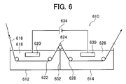
- FIG. 4 is a side view showing an example of a radial cell in an electrochemical surface roughening treatment using alternating current in the method for producing a lithographic printing plate support of the present invention.
- 50 is a main electrolytic cell
- 51 is an AC power source
- 52 is a radial drum roller
- 53a and 53b are main electrodes
- 54 is an electrolyte supply port
- 55 is an electrolyte
- 56 is a slit
- 57 is an electrolyte passage
- 58 is an auxiliary anode
- 60 is an auxiliary anode tank
- W is an aluminum plate.
- the electrolysis conditions may be the same or different.
- the aluminum plate W is wound around a radial drum roller 52 disposed so as to be immersed in the main electrolytic cell 50, and is subjected to electrolytic treatment by main electrodes 53a and 53b connected to the AC power source 51 in the course of conveyance.
- the electrolytic solution 55 is supplied from the electrolytic solution supply port 54 to the electrolytic solution passage 57 between the radial drum roller 52 and the main poles 53a and 53b through the slit 56.
- the aluminum plate W treated in the main electrolytic cell 50 is then subjected to electrolytic treatment in the auxiliary anode cell 60.
- An auxiliary anode 58 is disposed opposite to the aluminum plate W in the auxiliary anode tank 60, and the electrolytic solution 55 is supplied so as to flow in the space between the auxiliary anode 58 and the aluminum plate W.
- a direct current is applied between the aluminum plate and the electrode facing the aluminum plate to electrochemically roughen the surface. There may be.
- Drying step After obtaining the lithographic printing plate support obtained by the steps described above, it is preferable to perform a treatment (drying step) for drying the surface of the lithographic printing plate support before providing an image recording layer described later. Drying is preferably performed after the final treatment of the surface treatment, after washing with water and draining with a nip roller. Specific conditions are not particularly limited, but drying by hot air (50 to 200 ° C.) or a cold air natural drying method is preferable.
- the lithographic printing plate support of the present invention can be provided with an image recording layer such as a photosensitive layer and a heat-sensitive layer exemplified below to form the lithographic printing plate precursor of the present invention.
- the image recording layer is not particularly limited.
- a non-processing type that can be developed on the machine is preferable.
- a suitable image recording layer will be described in detail.
- a preferred image recording layer that can be used in the lithographic printing plate precursor according to the present invention is a layer that can be removed by printing ink and / or fountain solution.
- the image recording layer preferably has a polymerizable compound and can be recorded by infrared irradiation.
- the exposed portion of the image recording layer is cured by infrared irradiation to form a hydrophobic (lipophilic) region, and the unexposed portion is dampened with water, ink or ink at the start of printing. It is quickly removed from the support by an emulsion of fountain solution and ink.
- each component of the image recording layer will be described.
- an infrared absorber When forming an image of the lithographic printing plate precursor according to the present invention using a laser emitting an infrared ray of 760 to 1200 nm as a light source, an infrared absorber is usually used.
- the infrared absorber has a function of converting the absorbed infrared ray into heat and a function of being excited by the infrared ray and transferring electrons / energy to a polymerization initiator (radical generator) described later.
- the infrared absorber that can be used in the present invention is a dye or pigment having an absorption maximum at a wavelength of 760 to 1200 nm.
- dyes commercially available dyes, for example, known dyes described in documents such as “Dye Handbook” (edited by the Society for Synthetic Organic Chemistry, published in 1970) can be used. Specifically, dyes such as azo dyes, metal complex azo dyes, pyrazolone azo dyes, naphthoquinone dyes, anthraquinone dyes, phthalocyanine dyes, carbonium dyes, quinoneimine dyes, methine dyes, cyanine dyes, squarylium dyes, pyrylium salts, metal thiolate complexes, etc. Is mentioned. For example, the dyes disclosed in paragraphs [0096] to [0107] of JP2009-255434A can be suitably used.
- pigments described in paragraphs [0108] to [0112] of JP2009-255434A can be used.
- the polymerization initiator is a compound that generates radicals by energy of light, heat, or both, and initiates and accelerates polymerization of a compound having a polymerizable unsaturated group. In the present invention, it generates radicals by heat. It is preferable to use a compound (thermal radical generator).
- a known thermal polymerization initiator a compound having a bond with a small bond dissociation energy, a photopolymerization initiator, or the like can be used.
- polymerization initiator for example, polymerization initiators described in paragraphs [0115] to [0141] of JP-A-2009-255434 can be used.
- An onium salt or the like can be used as a polymerization initiator, and the oxime ester compound, diazonium salt, iodonium salt, or sulfonium salt is preferable from the viewpoint of reactivity and stability.
- These polymerization initiators are added in a proportion of 0.1 to 50% by mass, preferably 0.5 to 30% by mass, particularly preferably 1 to 20% by mass, based on the total solid content constituting the image recording layer. Can do. Within this range, good sensitivity and good stain resistance of the non-image area during printing can be obtained.
- the polymerizable compound is an addition polymerizable compound having at least one ethylenically unsaturated double bond, and is selected from compounds having at least one, preferably two or more terminal ethylenically unsaturated bonds.
- those compounds widely known in the technical field of the present invention can be used without any particular limitation.
- the polymerizable compound for example, polymerizable compounds exemplified in paragraphs [0142] to [0163] of JP2009-255434A can be used.
- urethane-based addition polymerizable compounds produced using an addition reaction of isocyanate and hydroxyl groups.
- Specific examples thereof include a vinyl monomer containing a hydroxyl group represented by the following general formula (A) in a polyisocyanate compound having two or more isocyanate groups per molecule described in JP-B-48-41708.
- vinyl urethane compounds containing two or more polymerizable vinyl groups in one molecule to which is added are also suitable.
- CH 2 C (R 4) COOCH 2 CH (R 5) OH (A) (However, R 4 and R 5 represent H or CH 3. )
- the polymerizable compound is preferably used in the range of 5 to 80% by mass, more preferably 25 to 75% by mass with respect to the non-volatile component in the image recording layer. These may be used alone or in combination of two or more.
- a binder polymer in the present invention, can be used for the image recording layer in order to improve the film forming property of the image recording layer.
- Conventionally known binder polymers can be used without limitation, and polymers having film properties are preferred.
- a binder polymer for example, acrylic resin, polyvinyl acetal resin, polyurethane resin, polyurea resin, polyimide resin, polyamide resin, epoxy resin, methacrylic resin, polystyrene resin, novolac phenolic resin, Polyester resin, synthetic rubber, natural rubber and the like can be mentioned.
- the binder polymer may have crosslinkability in order to improve the film strength of the image area.
- a crosslinkable functional group such as an ethylenically unsaturated bond may be introduced into the main chain or side chain of the polymer.
- the crosslinkable functional group may be introduced by copolymerization.
- binder polymer for example, binder polymers disclosed in paragraphs [0165] to [0172] of JP-A-2009-255434 can be used.
- the content of the binder polymer is 5 to 90% by mass, preferably 5 to 80% by mass, and more preferably 10 to 70% by mass with respect to the total solid content of the image recording layer. Within this range, good image area strength and image formability can be obtained. Further, the polymerizable compound and the binder polymer are preferably used in an amount of 0.5 / 1 to 4/1 by mass ratio.
- surfactant In the image recording layer, it is preferable to use a surfactant in order to promote on-press developability at the start of printing and to improve the coated surface state.
- the surfactant include nonionic surfactants, anionic surfactants, cationic surfactants, amphoteric surfactants, and fluorosurfactants.
- surfactant for example, surfactants disclosed in paragraphs [0175] to [0179] of JP2009-255434A can be used.
- Surfactant can be used individually or in combination of 2 or more types.
- the content of the surfactant is preferably 0.001 to 10% by mass, and more preferably 0.01 to 5% by mass, based on the total solid content of the image recording layer.
- various compounds may be added to the image recording layer as necessary.
- colorants, print-out agents, polymerization inhibitors, higher fatty acid derivatives, plasticizers, inorganic fine particles, low molecular weight hydrophilic compounds and the like disclosed in paragraphs [0181] to [0190] of JP-A-2009-255434 are disclosed. Can be mentioned.
- the image recording layer is formed by preparing a coating solution by dispersing or dissolving the necessary components described above in a solvent and then coating the coating solution on a support.
- the solvent used include ethylene dichloride, cyclohexanone, methyl ethyl ketone, methanol, ethanol, propanol, ethylene glycol monomethyl ether, 1-methoxy-2-propanol, 2-methoxyethyl acetate, 1-methoxy-2-propyl acetate, Although water etc. can be mentioned, it is not limited to this. These solvents are used alone or in combination.
- the solid content concentration of the coating solution is preferably 1 to 50% by mass.
- the coating amount (solid content) of the image recording layer on the lithographic printing plate support obtained after coating and drying varies depending on the use, but is generally preferably from 0.3 to 3.0 g / m 2 . Within this range, good sensitivity and good film characteristics of the image recording layer can be obtained.
- the coating method include bar coater coating, spin coating, spray coating, curtain coating, dip coating, air knife coating, blade coating, and roll coating.
- the undercoat layer preferably contains a polymer having a substrate adsorptive group, a polymerizable group, and a hydrophilic group.
- a polymer having a substrate adsorptive group, a polymerizable group and a hydrophilic group a monomer having an adsorptive group, a monomer having a hydrophilic group, and a monomer having a polymerizable reactive group (crosslinkable group) were copolymerized.
- polymer resins for undercoat layers examples include monomers described in paragraphs [0197] to [0210] of JP-A-2009-255434.
- the coating amount (solid content) of the undercoat layer is preferably 0.1 to 100 mg / m 2 , more preferably 1 to 50 mg / m 2 .
- a protective layer is provided on the image recording layer as necessary in order to prevent the occurrence of scratches in the image recording layer, to block oxygen, and to prevent ablation during high-illuminance laser exposure. Can do.
- the protective layer is described in detail in US Pat. No. 3,458,311 and JP-B-55-49729. Examples of the material used for the protective layer include materials described in paragraphs [0213] to [02227] of JP2009-255434A (water-soluble polymer compounds, inorganic layered compounds, etc.). be able to.
- the prepared protective layer coating solution is applied onto the image recording layer provided on the support and dried to form a protective layer.
- the coating solvent can be appropriately selected in relation to the binder, but when a water-soluble polymer is used, it is preferable to use distilled water or purified water.
- the coating method of the protective layer is not particularly limited, and examples thereof include a blade coating method, an air knife coating method, a gravure coating method, a roll coating coating method, a spray coating method, a dip coating method, and a bar coating method.
- the coating amount of the protective layer, the coating amount after drying is preferably in the range of 0.01 ⁇ 10g / m 2, more preferably in the range of 0.02 ⁇ 3g / m 2, and most preferably 0. It is in the range of 02 to 1 g / m 2 .
- the lithographic printing plate precursor of the present invention having the image recording layer as described above exhibits excellent neglectability and printing durability when used as a lithographic printing plate, while in-machine development type exhibits on-machine developability.
- An improved lithographic printing plate precursor is an improved lithographic printing plate precursor.
- the median diameter ( ⁇ m) of the abrasive was 30 ⁇ m
- the number of brushes was 4, and the number of rotations (rpm) of the brushes was 250 rpm.
- the material of the bunch planting brush was 6 ⁇ 10 nylon, with a bristle diameter of 0.3 mm and a bristle length of 50 mm.
- the brush was planted so as to be dense by making a hole in a stainless steel tube having a diameter of 300 mm.
- the distance between the two support rollers ( ⁇ 200 mm) at the bottom of the bundle-planting brush was 300 mm.
- the bundle brush was pressed until the load of the drive motor for rotating the brush became 10 kW plus with respect to the load before the bundle brush was pressed against the aluminum plate.
- the rotating direction of the brush was the same as the moving direction of the aluminum plate.
- Electrochemical roughening treatment An electrochemical roughening treatment was carried out continuously using an alternating voltage of nitric acid 60 Hz. As the electrolytic solution at this time, an electrolytic solution in which aluminum nitrate was adjusted to 4.5 g / L by adding aluminum nitrate to an aqueous solution having a temperature of 35 ° C. and nitric acid of 10.4 g / L was used.
- the AC power supply waveform is the waveform shown in FIG. 3. The time tp until the current value reaches a peak from zero is 0.8 msec, the duty ratio is 1: 1, and a trapezoidal rectangular wave AC is used with the carbon electrode as the counter electrode.
- An electrochemical roughening treatment was performed.
- Ferrite was used for the auxiliary anode.
- the electrolytic cell shown in FIG. 4 was used.
- the current density was 30 A / dm 2 at the peak current value, and 5% of the current flowing from the power source was shunted to the auxiliary anode.
- Amount of electricity (C / dm 2) the aluminum plate was 185C / dm 2 as the total quantity of electricity when the anode. Then, water washing by spraying was performed.
- Alkaline etching treatment The aluminum plate obtained above was etched by spraying a caustic soda aqueous solution having a caustic soda concentration of 5 mass% and an aluminum ion concentration of 0.5 mass% with a spray tube at a temperature of 50 ° C. . Then, water washing by spraying was performed. The amount of dissolved aluminum was 0.5 g / m 2 .
- desmutting treatment was performed in an aqueous sulfuric acid solution.
- the sulfuric acid aqueous solution used for the desmut treatment was a solution having a sulfuric acid concentration of 170 g / L and an aluminum ion concentration of 5 g / L.
- the liquid temperature was 30 ° C.
- the desmutting liquid was sprayed and sprayed for 3 seconds.
- Electrochemical roughening treatment An electrochemical roughening treatment was carried out continuously using an alternating voltage of hydrochloric acid electrolysis 60 Hz.
- As the electrolytic solution an electrolytic solution in which aluminum chloride was adjusted to 4.5 g / L by adding aluminum chloride to an aqueous solution having a liquid temperature of 35 ° C. and hydrochloric acid of 6.2 g / L was used.
- the AC power supply waveform is the waveform shown in FIG. 3.
- the time tp until the current value reaches a peak from zero is 0.8 msec, the duty ratio is 1: 1, and a trapezoidal rectangular wave AC is used with the carbon electrode as the counter electrode.
- An electrochemical roughening treatment was performed. Ferrite was used for the auxiliary anode.
- the electrolytic cell shown in FIG. 4 was used.
- the current density was 25A / dm 2 at the peak of electric current amount of hydrochloric acid electrolysis (C / dm 2) the aluminum plate was 63C / dm 2 as the total quantity of electricity when the anode. Then, water washing by spraying was performed.
- Alkaline etching treatment The aluminum plate obtained above was etched by spraying a caustic soda aqueous solution having a caustic soda concentration of 5 mass% and an aluminum ion concentration of 0.5 mass% with a spray tube at a temperature of 50 ° C. . Then, water washing by spraying was performed. The amount of aluminum dissolved was 0.1 g / m 2 .
- Desmutting treatment in acidic aqueous solution was performed in an aqueous sulfuric acid solution. Specifically, desmutting treatment was performed for 4 seconds at a liquid temperature of 35 ° C. using the waste liquid generated in the anodizing treatment step (dissolving 5 g / L of aluminum ions in a 170 g / L aqueous solution of sulfuric acid). The desmutting liquid was sprayed and sprayed for 3 seconds.
- (A-1) Second stage anodizing treatment was performed using an anodizing apparatus based on direct current electrolysis having the structure shown in FIG. Anodization was performed under the conditions shown in Table 1 to form an anodized film having a predetermined film thickness.
- BB Desmutting treatment in acidic aqueous solution
- desmut treatment was performed in an acidic aqueous solution.
- the acidic aqueous solution used for the desmut treatment was an aqueous solution of 150 g / L sulfuric acid.
- the liquid temperature was 30 ° C.
- the desmutting liquid was sprayed and sprayed for 3 seconds. Then, the water washing process was performed.
- the waveform of the alternating current is a sine wave in which positive and negative waveforms are symmetrical, the frequency is 50 Hz, the anode reaction time and the cathode reaction time in one cycle of the alternating current are 1: 1, and the current density is the peak current value of the alternating current waveform. It was 75 A / dm 2 .
- the amount of electricity is 450 C / dm 2 in terms of the total amount of electricity that the aluminum plate entrusts to the anode reaction, and the electrolytic treatment was performed four times at intervals of 125 C / dm 2 for 4 seconds.
- a carbon electrode was used as the counter electrode of the aluminum plate. Then, the water washing process was performed.
- Alkaline etching treatment Etching the aluminum plate after electrochemical surface roughening treatment by spraying a caustic soda aqueous solution with a caustic soda concentration of 5 mass% and an aluminum ion concentration of 0.5 mass% with a spray tube at a temperature of 35 ° C. Processed. The amount of aluminum dissolved on the surface subjected to the electrochemical surface roughening treatment was 0.1 g / m 2 . Then, the water washing process was performed.
- Second stage anodizing treatment was performed using a direct current electrolysis anodizing apparatus having the structure shown in FIG. Anodization was performed under the conditions shown in Table 1 to form an anodized film having a predetermined film thickness.
- Silicate treatment In order to ensure the hydrophilicity of the non-image area, a silicate treatment was performed by dipping at 50 ° C. for 7 seconds using an aqueous 2.5 mass% No. 3 sodium silicate solution. The adhesion amount of Si was 10 mg / m 2 . Then, water washing by spraying was performed.
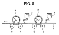
- ⁇ Process (C)> (Ca) Mechanical surface roughening (brush grain method) Using a device such as that shown in FIG. 5, while supplying a suspension of pumice (specific gravity 1.1 g / cm 3 ) as a polishing slurry liquid to the surface of the aluminum plate, a mechanical rough surface by a rotating bundle-planting brush The treatment was performed.
- the median diameter ( ⁇ m) of the abrasive was 30 ⁇ m
- the number of brushes was 4
- the number of rotations (rpm) of the brushes was 250 rpm.
- the material of the bunch planting brush was 6 ⁇ 10 nylon, the brush hair diameter was 0.3 mm, and the hair length was 50 mm.
- the brush was planted so as to be dense by making a hole in a stainless steel tube having a diameter of 300 mm.
- the distance between the two support rollers ( ⁇ 200 mm) at the bottom of the bundle-planting brush was 300 mm.
- the bundle brush was pressed until the load of the drive motor for rotating the brush became 10 kW plus with respect to the load before the bundle brush was pressed against the aluminum plate.
- the rotating direction of the brush was the same as the moving direction of the aluminum plate.
- (Cb) Alkaline etching treatment The aluminum plate obtained above was etched by spraying a caustic soda aqueous solution having a caustic soda concentration of 26 mass% and an aluminum ion concentration of 6.5 mass% with a spray tube at a temperature of 70 ° C. . Then, water washing by spraying was performed. The amount of aluminum dissolved was 10 g / m 2 .
- (Cf) Second stage anodizing treatment The second stage anodizing treatment was performed using a direct current electrolysis anodizing apparatus having the structure shown in FIG. Anodization was performed under the conditions shown in Table 1 to form an anodized film having a predetermined film thickness.
- (Cg) Silicate treatment In order to ensure the hydrophilicity of the non-image area, a silicate treatment was carried out by dipping at 50 ° C. for 7 seconds using an aqueous 2.5 mass% No. 3 sodium silicate solution. The adhesion amount of Si was 10 mg / m 2 . Then, water washing by spraying was performed.
- the brush was planted so as to be dense by making a hole in a stainless steel tube having a diameter of 300 mm.
- the distance between the two support rollers ( ⁇ 200 mm) at the bottom of the bundle-planting brush was 300 mm.
- the bundle brush was pressed until the load of the drive motor for rotating the brush became 10 kW plus with respect to the load before the bundle brush was pressed against the aluminum plate.
- the rotating direction of the brush was the same as the moving direction of the aluminum plate.
- Desmutting treatment in acidic aqueous solution Desmutting treatment was performed in an aqueous nitric acid solution.
- the nitric acid aqueous solution used for the desmut treatment was a nitric acid waste solution used for electrochemical roughening in the next step.
- the liquid temperature was 35 ° C.
- the desmutting liquid was sprayed and sprayed for 3 seconds.
- Electrochemical roughening treatment An electrochemical roughening treatment was carried out continuously using an alternating voltage of nitric acid electrolysis 60 Hz. As the electrolytic solution at this time, an electrolytic solution in which aluminum nitrate was adjusted to 4.5 g / L by adding aluminum nitrate to an aqueous solution having a temperature of 35 ° C. and nitric acid of 10.4 g / L was used.
- the AC power supply waveform is the waveform shown in FIG. 3. The time tp until the current value reaches a peak from zero is 0.8 msec, the duty ratio is 1: 1, and a trapezoidal rectangular wave AC is used with the carbon electrode as the counter electrode.
- An electrochemical roughening treatment was performed.
- Ferrite was used for the auxiliary anode.
- the electrolytic cell shown in FIG. 4 was used.
- the current density was 30 A / dm 2 at the peak current value, and 5% of the current flowing from the power source was shunted to the auxiliary anode.
- Amount of electricity (C / dm 2) the aluminum plate was 185C / dm 2 as the total quantity of electricity when the anode. Then, water washing by spraying was performed.
- (De) Alkaline etching treatment The aluminum plate obtained above was etched by spraying a caustic soda aqueous solution having a caustic soda concentration of 5 mass% and an aluminum ion concentration of 0.5 mass% with a spray tube at a temperature of 50 ° C. . Then, water washing by spraying was performed. The amount of dissolved aluminum was 0.5 g / m 2 .
- Desmutting treatment in acidic aqueous solution was carried out in an aqueous sulfuric acid solution.
- the sulfuric acid aqueous solution used for the desmut treatment was a solution having a sulfuric acid concentration of 170 g / L and an aluminum ion concentration of 5 g / L.
- the liquid temperature was 30 ° C.
- the desmutting liquid was sprayed and sprayed for 3 seconds.
- Second stage anodizing treatment was performed using a direct current electrolysis anodizing apparatus having the structure shown in FIG. Anodization was performed under the conditions shown in Table 1 to form an anodized film having a predetermined film thickness.
- (Dj) Silicate treatment In order to ensure the hydrophilicity of the non-image area, a silicate treatment was performed by dipping for 7 seconds at 50 ° C. using a 2.5 mass% No. 3 sodium silicate aqueous solution. The adhesion amount of Si was 10 mg / m 2 . Then, water washing by spraying was performed.
- Etching was performed by spraying an aqueous caustic soda solution having a caustic soda concentration of 26 mass% and an aluminum ion concentration of 6.5 mass% with a spray tube at a temperature of 70 ° C. on an aluminum plate. Then, water washing by spraying was performed. The amount of aluminum dissolved on the surface that was later subjected to electrochemical surface roughening was 5 g / m 2 .
- Electrochemical roughening treatment An electrochemical roughening treatment was carried out continuously using an alternating voltage of nitric acid electrolysis 60 Hz. As the electrolytic solution at this time, an electrolytic solution in which aluminum nitrate was adjusted to 4.5 g / L by adding aluminum nitrate to an aqueous solution having a temperature of 35 ° C. and nitric acid of 10.4 g / L was used.
- the AC power supply waveform is the waveform shown in FIG. 3. The time tp until the current value reaches a peak from zero is 0.8 msec, the duty ratio is 1: 1, and a trapezoidal rectangular wave AC is used with the carbon electrode as the counter electrode.
- An electrochemical roughening treatment was performed.
- Ferrite was used for the auxiliary anode.
- the electrolytic cell shown in FIG. 4 was used.
- the current density was 30 A / dm 2 at the peak current value, and 5% of the current flowing from the power source was shunted to the auxiliary anode.
- the amount of electricity (C / dm 2 ) was 250 C / dm 2 in terms of the total amount of electricity when the aluminum plate was an anode. Then, water washing by spraying was performed.
- Alkaline etching treatment The aluminum plate obtained above was etched by spraying a caustic soda aqueous solution having a caustic soda concentration of 5 mass% and an aluminum ion concentration of 0.5 mass% with a spray tube at a temperature of 50 ° C. . Then, water washing by spraying was performed. The amount of aluminum dissolved was 0.2 g / m 2 .
- (Eh) Second stage anodizing treatment The second stage anodizing treatment was performed using a direct current electrolysis anodizing apparatus having the structure shown in FIG. Anodization was performed under the conditions shown in Table 1 to form an anodized film having a predetermined film thickness.
- Silicate treatment In order to ensure the hydrophilicity of the non-image area, a silicate treatment was carried out by dipping at 50 ° C. for 7 seconds using an aqueous 2.5 mass% No. 3 sodium silicate solution. The adhesion amount of Si was 10 mg / m 2 . Then, water washing by spraying was performed.
- Electrochemical roughening treatment An electrochemical roughening treatment was carried out continuously using an alternating voltage of nitric acid electrolysis 60 Hz. As the electrolytic solution at this time, an electrolytic solution in which aluminum nitrate was adjusted to 4.5 g / L by adding aluminum nitrate to an aqueous solution having a temperature of 35 ° C. and nitric acid of 10.4 g / L was used.
- the AC power supply waveform is the waveform shown in FIG. 3. The time tp until the current value reaches a peak from zero is 0.8 msec, the duty ratio is 1: 1, and a trapezoidal rectangular wave AC is used with the carbon electrode as the counter electrode.
- An electrochemical roughening treatment was performed.
- Ferrite was used for the auxiliary anode.
- the electrolytic cell shown in FIG. 4 was used.
- the current density was 30 A / dm 2 at the peak current value, and 5% of the current flowing from the power source was shunted to the auxiliary anode.
- the amount of electricity (C / dm 2 ) was 250 C / dm 2 in terms of the total amount of electricity when the aluminum plate was an anode. Then, water washing by spraying was performed.
- desmutting treatment was performed in an aqueous sulfuric acid solution.
- the sulfuric acid aqueous solution used for the desmut treatment was a solution having a sulfuric acid concentration of 170 g / L and an aluminum ion concentration of 5 g / L.
- the liquid temperature was 30 ° C.
- the desmutting liquid was sprayed and sprayed for 3 seconds.
- Electrochemical roughening treatment An electrochemical roughening treatment was carried out continuously using an alternating voltage of hydrochloric acid electrolysis 60 Hz.
- As the electrolytic solution an electrolytic solution in which aluminum chloride was adjusted to 4.5 g / L by adding aluminum chloride to an aqueous solution having a liquid temperature of 35 ° C. and hydrochloric acid of 6.2 g / L was used.
- the AC power supply waveform is the waveform shown in FIG. 3.
- the time tp until the current value reaches a peak from zero is 0.8 msec, the duty ratio is 1: 1, and a trapezoidal rectangular wave AC is used with the carbon electrode as the counter electrode.
- An electrochemical roughening treatment was performed. Ferrite was used for the auxiliary anode.
- the electrolytic cell shown in FIG. 4 was used.
- the current density was 25A / dm 2 at the peak of electric current amount of hydrochloric acid electrolysis (C / dm 2) the aluminum plate was 63C / dm 2 as the total quantity of electricity when the anode. Then, water washing by spraying was performed.
- Second stage anodizing treatment was performed using a direct current electrolysis anodizing apparatus having the structure shown in FIG. Anodization was performed under the conditions shown in Table 1 to form an anodized film having a predetermined film thickness.
- (Fn) Silicate treatment To ensure the hydrophilicity of the non-image area, a silicate treatment was carried out by dipping at 50 ° C. for 7 seconds using a 2.5 mass% No. 3 sodium silicate aqueous solution. The adhesion amount of Si was 10 mg / m 2 . Then, water washing by spraying was performed.
- the diameters of the micropores existing in the range of 400 ⁇ 600 nm 2 were measured and averaged. If the depth of the large-diameter hole is deep and it is difficult to measure the diameter of the small-diameter hole, the upper part of the anodized film (region with the large-diameter hole) is cut if necessary, and then the small-diameter hole The diameter of was determined.
- the depth of the micropores was obtained by observing the cross section of the support (anodized film) with FE-SEM (large-diameter hole depth observation: 150,000 times) , Small diameter hole depth observation: 50,000 times) In the obtained image, the depth of 25 arbitrary micropores was measured and averaged.
- the AD amount in the first anodizing treatment column and the AD amount in the second anodizing treatment column represent the coating amount obtained in each treatment.
- the electrolytic solution used is an aqueous solution containing the components in Table 1.
- Comparative Examples 11 and 17 to 21 are conventional types in which the anodizing treatment is performed only once.
- the production conditions of Comparative Examples 12 to 16 are the same as those of Examples 1 to 5 described in paragraph [0136] of JP-A No. 11-219657.
- the image recording layer coating solution is bar-coated on the undercoat layer formed as described above, and then oven-dried at 100 ° C. for 60 seconds to form an image recording layer having a dry coating amount of 1.3 g / m 2. did. All the image recording layer coating solutions were obtained by mixing and stirring the respective photosensitive solutions and microgel solutions immediately before coating.
- Microgel solution > ⁇ Microgel (1) 2.640 g ⁇ Distilled water 2.425g
- the structures of the binder polymer (1), the infrared absorber (1), the radical polymerization initiator (1), the phosphonium compound (1), the low molecular weight hydrophilic compound (1) and the fluorine-based surfactant (1) are as follows: It is as shown below.
- microgel (1) described above was synthesized as follows.
- the oil phase component and the aqueous phase component were mixed and emulsified for 10 minutes at 12,000 rpm using a homogenizer.
- the obtained emulsion was added to 25 g of distilled water, stirred at room temperature for 30 minutes, and then stirred at 50 ° C. for 3 hours.
- the microgel solution thus obtained was diluted with distilled water to a solid content concentration of 15% by mass, and this was used as the microgel (1).
- the average particle size of the microgel was measured by a light scattering method, the average particle size was 0.2 ⁇ m.
- a protective layer coating solution having the following composition was further bar-coated on the image recording layer formed as described above, and then oven-dried at 120 ° C. for 60 seconds to provide a dry coating amount of 0.15 g / m 2 .
- a layer was formed to obtain a lithographic printing plate precursor.
- the inorganic layered compound dispersion liquid (1) described above is prepared as follows.
- ⁇ Evaluation of planographic printing plate> (On-press developability)
- the resulting lithographic printing plate precursor was exposed with a Luxel PLASETTER T-6000III manufactured by FUJIFILM Corporation equipped with an infrared semiconductor laser under the conditions of an outer drum rotation speed of 1000 rpm, a laser output of 70%, and a resolution of 2400 dpi.
- the exposure image includes a solid image and a 50% dot chart of a 20 ⁇ m dot FM screen.
- the obtained exposed original plate was attached to a plate cylinder of a printing machine LITHRONE 26 manufactured by Komori Corporation without developing.
- Print life After on-press development using the same printing machine and method as described above, printing was further continued. The printing durability was evaluated based on the number of printed sheets when it was visually recognized that the density of the solid image started to decrease.
- Table 3 In practice, it is preferable not to be “xxx”, “xxx”, or “x”.
- the scratch resistance of the lithographic printing plate support was evaluated by a scratch test on the surface of the obtained lithographic printing plate support.
- the scratch test was performed using a continuous load-type scratch strength tester (SB-53, manufactured by Shinto Kagaku Co., Ltd.) under conditions of a sapphire needle of 0.4 mm ⁇ and a needle moving speed of 10 cm / second under a load of 100 g.
- SB-53 continuous load-type scratch strength tester
- a lithographic printing plate and a lithographic printing plate precursor using a lithographic printing support provided with an anodic oxide coating of aluminum on which micropores having an average diameter and depth in a predetermined range are formed (implementation)
- a lithographic printing plate and a lithographic printing plate precursor using a lithographic printing support provided with an anodic oxide coating of aluminum on which micropores having an average diameter and depth in a predetermined range are formed (implementation)
- the large-diameter holes and the small-diameter holes constituting the micropores obtained in Examples 1 to 28 are both substantially straight pipes, and the bottom surfaces of the large-diameter holes are curved (substantially hemispherical). It was.
- Examples 3 and 4 in which the average diameter of the large-diameter hole portion is within a predetermined range, it was confirmed that a more excellent effect was obtained.
- Examples 7 and 8 in which the depth of the large-diameter hole is in a predetermined range,
- Examples 11 and 12 in which the ratio of the average diameter and depth of the large-diameter hole is in a predetermined range, and further, micropores It was confirmed that excellent effects were also obtained in Examples 15 and 16 in which the density of each was in a predetermined range.
- Comparative Examples 1 to 21 that did not satisfy the relationship between the average diameter and the depth of the present invention, only inferior results were obtained compared to Examples 1 to 28.
- Comparative Examples 12 to 16 in which Examples 1 to 5 specifically disclosed in JP-A No. 11-291657 were reproduced, results of inferior neglectability and on-press developability were obtained.
Landscapes
- Chemical & Material Sciences (AREA)
- Chemical Kinetics & Catalysis (AREA)
- Electrochemistry (AREA)
- Engineering & Computer Science (AREA)
- Materials Engineering (AREA)
- Metallurgy (AREA)
- Organic Chemistry (AREA)
- General Chemical & Material Sciences (AREA)
- Printing Plates And Materials Therefor (AREA)
- Materials For Photolithography (AREA)
- Photosensitive Polymer And Photoresist Processing (AREA)
Abstract
Description
すなわち、本発明は、以下の(1)~(10)を提供する。
該マイクロポアが、陽極酸化皮膜表面から深さ5~60nm(深さA)の位置までのびる大径孔部と、該大径孔部の底部と連通し、連通位置から深さ900~2000nmの位置までのびる小径孔部とから構成され、
大径孔部の陽極酸化皮膜表面における平均径が10~60nmで、該平均径と深さAとが(深さA/平均径)=0.1~4.0の関係を満たし、
小径孔部の該連通位置における平均径が0より大きく20nm未満であり、
該大径孔部の平均径と該小径孔部の平均径の比(小径孔部径/大径孔部径)が0.85以下であることを特徴とする平版印刷版用支持体。
(2) 前記大径孔部の平均径が10~50nmである、(1)に記載の平版印刷版用支持体。
(3) 前記深さAが10~50nmである、(1)または(2)に記載の平版印刷版用支持体。
(5) 前記マイクロポアの密度が100~3000個/μm2である、(1)~(4)のいずれかに記載の平版印刷版用支持体。
(6) アルミニウム板を陽極酸化する第1陽極酸化処理工程と、
前記第1陽極酸化処理工程で得られた陽極酸化皮膜を有するアルミニウム板を、酸水溶液またはアルカリ水溶液に接触させ、該陽極酸化皮膜中のマイクロポアの径を拡大させるポアワイド処理工程と、
前記ポアワイド処理工程で得られたアルミニウム板を陽極酸化する第2陽極酸化処理工程とを備え、(1)~(5)のいずれかに記載の平版印刷版用支持体を製造する、平版印刷版用支持体の製造方法。
(8) 前記第2陽極酸化処理工程において得られる陽極酸化皮膜の厚みが、900~2000nmである、(6)または(7)に記載の平版印刷版用支持体の製造方法。
(10) 前記画像記録層が、露光により画像を形成し、非露光部が印刷インキおよび/または湿し水により除去可能となる画像記録層である(9)に記載の平版印刷版原版。
また、機上現像型の平版印刷版においては、機上現像性を維持しつつ、耐刷性を向上することができる。
本発明の平版印刷版用支持体は、アルミニウム板とその上に形成される陽極酸化皮膜とを備え、陽極酸化皮膜中のマイクロポアが、平均径の大きい大径孔部と、平均径の小さい小径孔部とが深さ方向(皮膜の厚み方向)に沿って連結して構成される形状を有する。特に、本発明においては、マイクロポア中の平均径の大きい大径孔部の深さを制御することにより、トレードオフの関係とされていた放置払い性と耐刷性、または、機上現像性と耐刷性との関係を、より高いレベルで両立することができる。
同図に示す平版印刷版用支持体10は、アルミニウム板12とアルミニウムの陽極酸化皮膜14とをこの順で積層した積層構造を有する。陽極酸化皮膜14は、その表面からアルミニウム板12側に向かってのびるマイクロポア16を有し、マイクロポア16は大径孔部18と小径孔部20とから構成される。
まず、アルミニウム板12および陽極酸化皮膜14について詳述する。
本発明に用いられるアルミニウム板12(アルミニウム支持体)は、寸度的に安定なアルミニウムを主成分とする金属であり、アルミニウムまたはアルミニウム合金からなる。純アルミニウム板の他、アルミニウムを主成分とし、微量の異元素を含む合金板、またはアルミニウム(合金)がラミネートもしくは蒸着されたプラスチックフィルムもしくは紙の中から選ばれる。更に、特公昭48-18327号公報に記載されているようなポリエチレンテレフタレートフィルム上にアルミニウムシートが結合された複合体シートでもかまわない。
陽極酸化皮膜14は、陽極酸化処理によってアルミニウム板12の表面に一般的に作製される、皮膜表面に垂直であり、個々が均一に分布した極微細なマイクロポア16を有する陽極酸化アルミニウム皮膜を指す。該マイクロポア16は、アルミニウム板12とは反対側の陽極酸化皮膜表面から厚み方向(アルミニウム板12側)に沿ってのびる。
以下に、大径孔部18と小径孔部20について詳述する。
大径孔部18の陽極酸化皮膜表面における平均径(平均開口径)は、10~60nmである。該範囲であれば、該平版印刷版用支持体を用いて得られる平版印刷版の優れた耐刷性、放置払い性、および該支持体を用いて得られる平版印刷版原版の優れた機上現像性が達成される。該平版印刷版用支持体を用いて得られる平版印刷版の耐刷性がより優れる点で、平均径は10~50nmであることが好ましく、15~50nmであることがより好ましく、20~50nmであることがさらに好ましい。
平均径が10nm未満の場合、十分なアンカー効果が得られず、平版印刷版の耐刷性向上が得られない。また、平均径が60nmを超える場合、粗面化した砂目を壊してしまい、耐刷性や放置払い性などの各種性能の向上が得られない。
大径孔部18の平均径は、陽極酸化皮膜14表面を倍率15万倍のFE-SEMでN=4枚観察し、得られた4枚の画像において、400×600nm2の範囲に存在するマイクロポア(大径孔部)の径を測定し、平均した値である。
なお、大径孔部18の形状が円状でない場合は、円相当径を用いる。「円相当径」とは、開口部の形状を、開口部の投影面積と同じ投影面積をもつ円と想定したときの当該円の直径である。
深さが5nm未満の場合、十分なアンカー効果が得られず、平版印刷版の耐刷性向上が得られない。深さが60nmを超える場合、平版印刷版の放置払い性と平版印刷版原版の機上現像性が劣る。
なお、上記深さは、陽極酸化皮膜14の断面の写真(15万倍)をとり、25個以上の大径孔部の深さを測定し、平均した値である。
(深さA/平均径)が0.1未満の場合、平版印刷版の耐刷性向上が得られない。(深さA/平均径)が4.0を超える場合、平版印刷版の放置払い性と平版印刷版原版の機上現像性が劣る。
大径孔部18の内径は特に制限されないが、通常、開口部の径と同程度の大きさか、または開口部の径よりも小さい。なお、大径孔部18の内径は、通常、開口部の径よりも1~10nm程度の差があってもよい。
小径孔部20は、図1に示すように、大径孔部18の底部と連通して、連通位置よりさらに深さ方向(厚み方向)に延びる孔部である。ひとつの小径孔部20は、通常ひとつの大径孔部18と連通するが、2つ以上の小径孔部20がひとつの大径孔部18の底部と連通していてもよい。
小径孔部20の連通位置における平均径は0より大きく20nm未満である。放置払い性、機上現像性の点で、平均径は15nm以下が好ましく、13nm以下がより好ましく、5~10nmが特に好ましい。
平均径が20nm以上の場合、本発明の平版印刷版用支持体を用いた平版印刷版の放置払い性や、平版印刷版原版の機上現像性が劣る。
小径孔部20の平均径は、陽極酸化皮膜14表面を倍率15万倍のFE-SEMでN=4枚観察し、得られた4枚の画像において、400×600nm2の範囲に存在するマイクロポア(小径孔部)の径を測定し、平均した値である。なお、大径孔部の深さが深い場合は、必要に応じて、陽極酸化皮膜14上部(大径孔部のある領域)を切削し(例えば、アルゴンガスによって切削)、その後陽極酸化皮膜14表面を上記FE-SEMで観察して、小径孔部の平均径を求めてもよい。
なお、小径孔部20の形状が円状でない場合は、円相当径を用いる。「円相当径」とは、開口部の形状を、開口部の投影面積と同じ投影面積をもつ円と想定したときの当該円の直径である。
深さが900nm未満の場合、平版印刷版用支持体の耐傷性が劣る。深さが2000nmを超える場合、処理時間が長期化し、生産性および経済性に劣る。
なお、上記深さは、陽極酸化皮膜14の断面の写真(5万倍)をとり、25個以上の小径孔部の深さを測定し、平均した値である。
平均径の比が0.85を超えると、耐刷性と放置汚れ性/機上現像性との両立が取れない点で劣る。
小径孔部20の内径は特に制限されないが、通常、連通位置における径と同程度の大きさか、または該径よりも小さくても大きくてもよい。なお、小径孔部20の内径は、通常、開口部の径よりも1~10nm程度の差があってもよい。
以下に本発明の平版印刷版用支持体の製造方法について説明する。
本発明の平版印刷版用支持体の製造方法は特に限定されないが、以下の工程を順番に実施する製造方法が好ましい。
(粗面化処理工程)アルミニウム板に粗面化処理を施す工程
(第1陽極酸化処理工程)粗面化処理されたアルミニウム板を陽極酸化する工程
(ポアワイド処理工程)第1陽極酸化処理工程で得られた陽極酸化皮膜を有するアルミニウム板を、酸水溶液またはアルカリ水溶液に接触させ、該陽極酸化皮膜中のマイクロポアの径を拡大させる工程
(第2陽極酸化処理工程)ポアワイド処理工程で得られたアルミニウム板を陽極酸化する工程
(親水化処理工程)第2陽極酸化処理工程で得られたアルミニウム板に親水化処理を施す工程
以下に上記各工程について詳述する。なお、粗面化処理工程および親水化処理工程は、発明の効果上、必要がなければ実施しなくてもよい。また、図2において、第1陽極酸化処理工程から第2陽極酸化処理工程までを工程順に示す基板および陽極酸化皮膜の模式的断面図を示す。
粗面化処理工程は、上述したアルミニウム板の表面に、電気化学的粗面化処理を含む粗面化処理を施す工程である。該工程は、後述する第1陽極酸化処理工程の前に実施されることが好ましいが、アルミニウム板の表面がすでに好ましい表面形状を有していれば、特に実施しなくてもよい。
機械的粗面化処理と電気化学的粗面化処理とを組み合わせる場合には、機械的粗面化処理の後に、電気化学的粗面化処理を施すのが好ましい。
本発明においては、機械的粗面化処理の諸条件は特に限定されないが、例えば、特公昭50-40047号公報に記載されている方法に従って施すことができる。機械的粗面化処理は、パミストン懸濁液を使用したブラシグレイン処理により施したり、転写方式で施したりすることができる。
また、化学的粗面化処理も特に限定されず、公知の方法に従って施すことができる。
機械的粗面化処理の後に施される化学エッチング処理は、アルミニウム板の表面の凹凸形状のエッジ部分をなだらかにし、印刷時のインキの引っかかりを防止し、平版印刷版の耐汚れ性を向上させるとともに、表面に残った研磨材粒子等の不要物を除去するために行われる。
化学エッチング処理としては、酸によるエッチングやアルカリによるエッチングが知られているが、エッチング効率の点で特に優れている方法として、アルカリ溶液を用いる化学エッチング処理(以下、「アルカリエッチング処理」ともいう。)が挙げられる。
また、各アルカリ剤は、アルミニウムイオンを含有してもよい。アルカリ溶液の濃度は、0.01質量%以上であるのが好ましく、3質量%以上であるのがより好ましく、また、30質量%以下であるのが好ましく、25質量%以下であるのがより好ましい。
更に、アルカリ溶液の温度は室温以上であるのが好ましく、30℃以上であるのがより好ましく、80℃以下であるのが好ましく、75℃以下であるのがより好ましい。
また、処理時間は、エッチング量に対応して2秒~5分であるのが好ましく、生産性向上の点から2~10秒であるのがより好ましい。
酸性溶液に用いられる酸は、特に限定されないが、例えば、硫酸、硝酸、塩酸が挙げられる。酸性溶液の濃度は、1~50質量%であるのが好ましい。また、酸性溶液の温度は、20~80℃であるのが好ましい。酸性溶液の濃度および温度がこの範囲であると、本発明の平版印刷版用支持体を用いた平版印刷版の耐ポツ状汚れ性がより向上する。
電気化学的粗面化処理は、硝酸または塩酸を主体とする水溶液中で、直流または交流を用いて行われる。
また、電気化学的粗面化処理後にアルカリエッチング処理を行わない場合においても、スマットを効率よく除去するため、デスマット処理を行うのが好ましい。
第1陽極酸化処理工程は、上述した粗面化処理が施されたアルミニウム板に陽極酸化処理を施すことにより、該アルミニウム板表面に深さ方向(厚み方向)にのびるマイクロポアを有するアルミニウムの酸化皮膜を形成する工程である。この第1陽極酸化処理により、図2(A)に示されるように、アルミニウム板12の表面に、マイクロポア16aを有するアルミニウムの陽極酸化皮膜14aが形成される。
具体的には、第1陽極酸化処理工程において形成されるマイクロポア16aの平均径(平均開口径)は、通常、4~14nm程度であり、好ましくは5~10nmである。上記範囲内であれば、上述した所定の形状を有するマイクロポア16が形成しやすく、得られる平版印刷版および平版印刷版原版の性能もより優れる。
また、マイクロポア16aの深さは、通常、10nm以上100nm未満程度であり、好ましくは20~60nmである。上記範囲内であれば、上述した所定の形状を有するマイクロポア16が形成しやすく、得られる平版印刷版および平版印刷版原版の性能もより優れる。
さらに、第1陽極酸化処理工程により得られる陽極酸化皮膜の皮膜量は、0.1~0.3g/m2が好ましく、より好ましくは0.12~0.25g/m2である。上記範囲内であれば、該工程を経て得られる平版印刷版用支持体を用いた平版印刷版の耐刷性および放置払い性、並びに、平版印刷版原版の機上現像性に優れる。
なお、電解浴にはアルミニウムイオンが含まれていてもよい。アルミニウムイオンの含有量は特に限定されないが、1~10g/Lが好ましい。
ポアワイド処理工程は、上述した第1陽極酸化処理工程により形成された陽極酸化皮膜に存在するマイクロポアの径(ポア径)を拡大させる処理(孔径拡大処理)である。このポアワイド処理により、図2(B)に示されるように、マイクロポア16aの径が拡大され、より大きな平均径を有するマイクロポア16bを有する陽極酸化皮膜14bが形成される。
このポアワイド処理により、マイクロポア16bの平均径は、10~60nm(好ましくは、10~50nm)の範囲まで拡大される。なお、このマイクロポア16bは、上述した大径孔部18に該当する部分となる。
また、該処理により、マイクロポア16bの表面からの深さは、上述した深さAと同程度となるように調整することが好ましい。
なお、アルカリ水溶液のpHを11~13に調整した後、10~70℃(好ましくは20~50℃)の条件下で、アルミニウム板をアルカリ水溶液に1~300秒(好ましくは1~50秒)接触させることが適当である。
この際、アルカリ処理液中に炭酸塩、硼酸塩、燐酸塩等の多価弱酸の金属塩を含んでもよい。
なお、酸水溶液の液温5~70℃(好ましくは10~60℃)の条件下で、アルミニウム板を酸水溶液に1~300秒(好ましくは1~150秒)接触させることが適当である。
なお、アルカリ水溶液または酸水溶液中にはアルミニウムイオンが含まれていてもよい。アルミニウムイオンの含有量は特に限定されないが、1~10g/Lが好ましい。
第2陽極酸化処理工程は、上述したポアワイド処理が施されたアルミニウム板に陽極酸化処理を施すことにより、より深さ方向(厚み方向)にのびたマイクロポアを形成する工程である。この第2陽極酸化処理工程により、図2(C)に示されるように、深さ方向にのびたマイクロポア16cを有する陽極酸化皮膜14cが形成される。
この第2陽極酸化処理工程によって、平均径が拡大されたマイクロポア16bの底部に連通し、平均径がマイクロポア16b(大径孔部18に該当)の平均径より小さく、連通位置から深さ方向にのびる新たな孔部が形成される。該孔部が、上述した小径孔部20に該当する。
陽極酸化処理の条件は使用される電解液によって適宜設定されるが、一般的には、電解液の濃度が1~80質量%(好ましくは5~20質量%)、液温5~70℃(好ましくは10~60℃)、電流密度0.5~60A/dm2(好ましくは1~30A/dm2)、電圧1~100V(好ましくは5~50V)、電解時間1~100秒(好ましくは5~60秒)の範囲が適当である。
また、第2陽極酸化処理工程により得られる陽極酸化皮膜の皮膜量は、通常、2.2~5.4g/m2であり、好ましくは2.2~4.0g/m2である。上記範囲内であれば、該工程を経て得られる平版印刷版用支持体を用いた平版印刷版の耐刷性および放置払い性、並びに、平版印刷版原版の機上現像性に優れる。
本発明の平版印刷版用支持体の製造方法は、上述した第2陽極酸化処理工程の後、親水化処理を施す親水化処理工程を有していてもよい。なお、親水化処理としては、特開2005-254638号公報の段落[0109]~[0114]に開示される公知の方法が使用できる。
(2)アルカリ水溶液中で化学エッチング処理(第1アルカリエッチング処理)
(3)酸性水溶液中で化学エッチング処理(第1デスマット処理)
(4)硝酸を主体とする水溶液中で電気化学的粗面化処理(第1電気化学的粗面化処理)
(5)アルカリ水溶液中で化学エッチング処理(第2アルカリエッチング処理)
(6)酸性水溶液中で化学エッチング処理(第2デスマット処理)
(7)塩酸を主体とする水溶液中で電気化学的粗面化処理(第2電気化学的粗面化処理)
(8)アルカリ水溶液中で化学エッチング処理(第3アルカリエッチング処理)
(9)酸性水溶液中で化学エッチング処理(第3デスマット処理)
(10)陽極酸化処理(第1陽極酸化処理および第2陽極酸化処理)
(11)親水化処理
(2)アルカリ水溶液中で化学エッチング処理(第1アルカリエッチング処理)
(3)酸性水溶液中で化学エッチング処理(第1デスマット処理)
(12)塩酸を主体とする水溶液中で電気化学的粗面化処理
(5)アルカリ水溶液中で化学エッチング処理(第2アルカリエッチング処理)
(6)酸性水溶液中で化学エッチング処理(第2デスマット処理)
(10)陽極酸化処理(第1陽極酸化処理および第2陽極酸化処理)
(11)親水化処理
ここで、上記(1)~(12)における機械的粗面化処理、電気化学的粗面化処理、化学エッチング処理、陽極酸化処理および親水化処理は、上述した処理方法、条件と同様の方法で行うことができるが、以下に説明する処理方法、条件で施すのが好ましい。
研磨剤としては公知の物が使用できるが、珪砂、石英、水酸化アルミニウムまたはこれらの混合物が好ましい。
スラリー液の比重は1.05~1.3が好ましい。勿論、スラリー液を吹き付ける方式、ワイヤーブラシを用いる方式、凹凸を付けた圧延ロールの表面形状をアルミニウム板に転写する方式などを用いてもよい。
アルカリ水溶液としては、特に苛性ソーダを主体とする水溶液が好ましい。液温は常温~95℃で、1~120秒間処理するのが好ましい。
エッチング処理が終了した後には、処理液を次工程に持ち込まないためにニップローラーによる液切りとスプレーによる水洗を行うのが好ましい。
第2アルカリエッチング処理におけるアルミニウム板の溶解量は、0.001~30g/m2であるのが好ましく、0.1~4g/m2であるのがより好ましく、0.2~1.5g/m2であるのが更に好ましい。
第3アルカリエッチング処理におけるアルミニウム板の溶解量は、0.001~30g/m2であるのが好ましく、0.01~0.8g/m2であるのがより好ましく、0.02~0.3g/m2であるのが更に好ましい。
酸性水溶液の濃度は0.5~60質量%が好ましい。
また、酸性水溶液中にはアルミニウムおよびアルミニウム合金中に含有する合金成分が0~5質量%溶解していてもよい。
また、液温は常温から95℃で実施され、処理時間は1~120秒が好ましい。デスマット処理が終了した後には、処理液を次工程に持ち込まないためにニップローラーによる液切りとスプレーによる水洗を行うのが好ましい。
第1電気化学的粗面化処理で用いる硝酸を主体とする水溶液は、通常の直流または交流を用いた電気化学的な粗面化処理に用いるものを使用でき、1~100g/Lの硝酸水溶液に、硝酸アルミニウム、硝酸ナトリウム、硝酸アンモニウムなどの硝酸イオン;塩化アルミニウム、塩化ナトリウム、塩化アンモニウムなどの塩酸イオン;等を有する塩酸または硝酸化合物の1つ以上を1g/L~飽和まで添加して使用することができる。
また、硝酸を主体とする水溶液中には、鉄、銅、マンガン、ニッケル、チタン、マグネシウム、シリカ等のアルミニウム合金中に含まれる金属が溶解していてもよい。
具体的には、硝酸0.5~2質量%水溶液中にアルミニウムイオンが3~50g/Lとなるように塩化アルミニウム、硝酸アルミニウムを添加した液を用いるのが好ましい。
また、温度は10~90℃が好ましく、40~80℃がより好ましい。
また、塩酸を主体とする水溶液中には、鉄、銅、マンガン、ニッケル、チタン、マグネシウム、シリカ等のアルミニウム合金中に含まれる金属が溶解していてもよい。
具体的には、塩酸0.5~2質量%水溶液中にアルミニウムイオンが3~50g/Lとなるように塩化アルミニウム、硝酸アルミニウムを添加した液を用いるのが好ましい。
また、温度は10~60℃が好ましく、20~50℃がより好ましい。なお、次亜塩素酸を添加してもよい。
一方、B態様における塩酸水溶液中での電気化学的粗面化処理で用いる塩酸を主体とする水溶液は、通常の直流または交流を用いた電気化学的な粗面化処理に用いるものを使用でき、1~100g/Lの塩酸水溶液に、硫酸を0~30g/L添加して使用することができる。また、この溶液に、硝酸アルミニウム、硝酸ナトリウム、硝酸アンモニウムなどの硝酸イオン;塩化アルミニウム、塩化ナトリウム、塩化アンモニウムなどの塩酸イオン;等を有する塩酸または硝酸化合物の1つ以上を1g/L~飽和まで添加して使用することができる。
また、塩酸を主体とする水溶液中には、鉄、銅、マンガン、ニッケル、チタン、マグネシウム、シリカ等のアルミニウム合金中に含まれる金属が溶解していてもよい。
具体的には、硝酸0.5~2質量%水溶液中に、アルミニウムイオンが3~50g/Lとなるように塩化アルミニウム、硝酸アルミニウム等を添加した液を用いるのが好ましい。
また、温度は10~60℃が好ましく、20~50℃がより好ましい。なお、次亜塩素酸を添加してもよい。
図3において、taはアノード反応時間、tcはカソード反応時間、tpは電流が0からピークに達するまでの時間、Iaはアノードサイクル側のピーク時の電流、Icはカソードサイクル側のピーク時の電流である。台形波において、電流が0からピークに達するまでの時間tpは1~10msecが好ましい。電源回路のインピーダンスの影響のため、tpが1未満であると電流波形の立ち上がり時に大きな電源電圧が必要となり、電源の設備コストが高くなる。10msecより大きくなると、電解液中の微量成分の影響を受けやすくなり均一な粗面化が行われにくくなる。電気化学的な粗面化に用いる交流の1サイクルの条件が、アルミニウム板のアノード反応時間taとカソード反応時間tcの比tc/taが1~20、アルミニウム板がアノード時の電気量Qcとアノード時の電気量Qaの比Qc/Qaが0.3~20、アノード反応時間taが5~1000msec、の範囲にあるのが好ましい。tc/taは2.5~15であるのがより好ましい。Qc/Qaは2.5~15であるのがより好ましい。電流密度は台形波のピーク値で電流のアノードサイクル側Ia、カソードサイクル側Icともに10~200A/dm2が好ましい。Ic/Iaは0.3~20の範囲にあるのが好ましい。電気化学的な粗面化が終了した時点でのアルミニウム板のアノード反応にあずかる電気量の総和は25~1000C/dm2が好ましい。
図4は、本発明の平版印刷版用支持体の製造方法における交流を用いた電気化学的粗面化処理におけるラジアル型セルの一例を示す側面図である。
図4において、50は主電解槽、51は交流電源、52はラジアルドラムローラ、53a,53bは主極、54は電解液供給口、55は電解液、56はスリット、57は電解液通路、58は補助陽極、60は補助陽極槽、Wはアルミニウム板である。電解槽を2つ以上用いるときには、電解条件は同じでもよいし、異なっていてもよい。
アルミニウム板Wは主電解槽50中に浸漬して配置されたラジアルドラムローラ52に巻装され、搬送過程で交流電源51に接続する主極53a、53bにより電解処理される。電解液55は電解液供給口54からスリット56を通じてラジアルドラムローラ52と主極53a、53bとの間の電解液通路57に供給される。主電解槽50で処理されたアルミニウム板Wは次いで補助陽極槽60で電解処理される。この補助陽極槽60には補助陽極58がアルミニウム板Wと対向配置されており、電解液55が補助陽極58とアルミニウム板Wとの間の空間を流れるように供給される。
上述した工程により得られた平版印刷版用支持体を得た後、後述する画像記録層を設ける前に、平版印刷版用支持体の表面を乾燥させる処理(乾燥工程)を施すのが好ましい。
乾燥は、表面処理の最後の処理の後、水洗処理およびニップローラーで液切りしてから行うのが好ましい。具体的な条件としては特に制限されないが、熱風(50~200℃)、または、冷風自然乾燥法等で乾燥することが好ましい。
本発明の平版印刷版用支持体には、以下に例示する感光層、感熱層等の画像記録層を設けて本発明の平版印刷版原版とすることができる。画像記録層は、特に限定されないが、例えば、特開2003-1956号公報の段落[0042]~[0198]に記載される、コンベンショナルポジタイプ、コンベンショナルネガタイプ、フォトポリマータイプ、サーマルポジタイプ、サーマルネガタイプ、機上現像可能な無処理タイプが好適に挙げられる。
以下、好適な画像記録層について、詳細に説明する。
本発明の平版印刷版原版に用いることができる好ましい画像記録層としては、印刷インキおよび/または湿し水により除去可能なものであり、具体的には、赤外線吸収剤と、重合開始剤と、重合性化合物を有し、赤外線の照射により記録可能な画像記録層であるのが好ましい。
本発明の平版印刷版原版においては、赤外線の照射により画像記録層の露光部が硬化して疎水性(親油性)領域を形成し、かつ、印刷開始時に未露光部が湿し水、インキまたは湿し水とインキとの乳化物によって支持体上から速やかに除去される。
以下、画像記録層の各構成成分について説明する。
本発明の平版印刷版原版を、760~1200nmの赤外線を発するレーザーを光源として画像形成する場合には、通常、赤外線吸収剤を用いる。
赤外線吸収剤は、吸収した赤外線を熱に変換する機能と赤外線により励起して後述する重合開始剤(ラジカル発生剤)に電子移動/エネルギー移動する機能を有する。
本発明において使用することができる赤外線吸収剤は、波長760~1200nmに吸収極大を有する染料または顔料である。
具体的には、アゾ染料、金属錯塩アゾ染料、ピラゾロンアゾ染料、ナフトキノン染料、アントラキノン染料、フタロシアニン染料、カルボニウム染料、キノンイミン染料、メチン染料、シアニン染料、スクワリリウム色素、ピリリウム塩、金属チオレート錯体等の染料が挙げられる。例えば、特開2009-255434号公報の段落[0096]~[0107]に開示される染料を好適に使用することができる。
上記重合開始剤は、光、熱あるいはその両方のエネルギーによりラジカルを発生し、重合性の不飽和基を有する化合物の重合を開始、促進する化合物であり、本発明においては、熱によりラジカルを発生する化合物(熱ラジカル発生剤)を使用するのが好ましい。
上記重合開始剤としては、公知の熱重合開始剤や結合解離エネルギーの小さな結合を有する化合物、光重合開始剤などを使用することができる。
重合開始剤としては、例えば、特開2009-255434号公報の段落[0115]~[0141]に記載される重合開始剤などが利用できる。
重合性化合物は、少なくとも一個のエチレン性不飽和二重結合を有する付加重合性化合物であり、末端エチレン性不飽和結合を少なくとも1個、好ましくは2個以上有する化合物から選択される。本発明においては、このような化合物は本発明の技術分野において広く知られるものを特に限定無く用いることができる。
重合性化合物としては、例えば、特開2009-255434号公報の段落[0142]~[0163]に例示される重合性化合物などが使用できる。
(ただし、R4およびR5は、HまたはCH3を示す。)
本発明においては、画像記録層には、画像記録層の皮膜形成性を向上させるためバインダーポリマーを用いることができる。
バインダーポリマーは従来公知のものを制限なく使用でき、皮膜性を有するポリマーが好ましい。このようなバインダーポリマーとしては、具体的には、例えば、アクリル樹脂、ポリビニルアセタール樹脂、ポリウレタン樹脂、ポリウレア樹脂、ポリイミド樹脂、ポリアミド樹脂、エポキシ樹脂、メタクリル樹脂、ポリスチレン系樹脂、ノボラック型フェノール系樹脂、ポリエステル樹脂、合成ゴム、天然ゴム等が挙げられる。
バインダーポリマーは、画像部の皮膜強度を向上するために、架橋性を有していてもよい。バインダーポリマーに架橋性を持たせるためには、エチレン性不飽和結合等の架橋性官能基を高分子の主鎖中または側鎖中に導入すればよい。架橋性官能基は、共重合により導入してもよい。
バインダーポリマーとしては、例えば、特開2009-255434号公報の段落[0165]~[0172]に開示されるバインダーポリマーを使用することもできる。
また、重合性化合物とバインダーポリマーは、質量比で0.5/1~4/1となる量で用いるのが好ましい。
画像記録層には、印刷開始時の機上現像性を促進させるため、および、塗布面状を向上させるために界面活性剤を用いるのが好ましい。
界面活性剤としては、ノニオン界面活性剤、アニオン界面活性剤、カチオン界面活性剤、両性界面活性剤、フッ素系界面活性剤等が挙げられる。
界面活性剤としては、例えば、特開2009-255434号公報の段落[0175]~[0179]に開示される界面活性剤などを使用できる。
界面活性剤の含有量は、画像記録層の全固形分に対して、0.001~10質量%であるのが好ましく、0.01~5質量%であるのがより好ましい。
画像記録層は、必要な上記各成分を溶剤に分散または溶かして塗布液を調製した後、該塗布液を支持体上に塗布することにより形成される。ここで、使用する溶剤としては、エチレンジクロライド、シクロヘキサノン、メチルエチルケトン、メタノール、エタノール、プロパノール、エチレングリコールモノメチルエーテル、1-メトキシ-2-プロパノール、2-メトキシエチルアセテート、1-メトキシ-2-プロピルアセテート、水等を挙げることができるが、これに限定されるものではない。
これらの溶剤は、単独または混合して使用される。塗布液の固形分濃度は、好ましくは1~50質量%である。
塗布する方法としては、例えば、バーコーター塗布、回転塗布、スプレー塗布、カーテン塗布、ディップ塗布、エアナイフ塗布、ブレード塗布、ロール塗布等を挙げられる。
本発明の平版印刷版原版においては、上述した画像記録層と平版印刷版用支持体との間に下塗り層を設けることが望ましい。
基板吸着性基、重合性基および親水性基を有するポリマーとしては、吸着性基を有するモノマー、親水性基を有するモノマー、および、重合性反応基(架橋性基)を有するモノマーを共重合した下塗り層用高分子樹脂を挙げることができる。
下塗り層用高分子樹脂に使用できるモノマーとしては、例えば、特開2009-255434号公報の段落[0197]~[0210]などに記載されるモノマーが挙げられる。
下塗り層の塗布量(固形分)は、0.1~100mg/m2であるのが好ましく、1~50mg/m2であるのがより好ましい。
本発明の平版印刷版原版においては、画像記録層における傷等の発生防止、酸素遮断、高照度レーザー露光時のアブレーション防止のため、必要に応じて、画像記録層の上に保護層を設けることができる。
保護層については、以前より種々検討がなされており、例えば、米国特許第3、458、311号明細書および特公昭55-49729号公報に詳細に記載されている。
また、保護層に用いられる材料としては、例えば、特開2009-255434号公報の段落[0213]~[02227]などに記載される材料(水溶性高分子化合物、無機質の層状化合物など)を用いることができる。
厚さ0.3mmの材質1Sのアルミニウム合金板に対し、下記(A)から(F)のうち下記第1表に示す処理を施し、平版印刷版用支持体を製造した。なお、全ての処理工程の間には水洗処理を施し、水洗処理の後にはニップローラーで液切りを行った。
(A-a)機械的粗面化処理(ブラシグレイン法)
図5に示したような装置を使って、パミスの懸濁液(比重1.1g/cm3)を研磨スラリー液としてアルミニウム板の表面に供給しながら、回転する束植ブラシにより機械的粗面化処理を行った。図5において、1はアルミニウム板、2および4はローラ状ブラシ(本実施例において、束植ブラシ)、3は研磨スラリー液、5、6、7および8は支持ローラである。
機械的粗面化処理は、研磨材のメジアン径(μm)を30μm、ブラシ本数を4本、ブラシの回転数(rpm)を250rpmとした。束植ブラシの材質は6・10ナイロンで、ブラシ毛の直径0.3mm、毛長50mmであった。ブラシは、φ300mmのステンレス製の筒に穴をあけて密になるように植毛した。束植ブラシ下部の2本の支持ローラ(φ200mm)の距離は300mmであった。束植ブラシはブラシを回転させる駆動モータの負荷が、束植ブラシをアルミニウム板に押さえつける前の負荷に対して10kWプラスになるまで押さえつけた。ブラシの回転方向はアルミニウム板の移動方向と同じであった。
上記で得られたアルミニウム板に、カセイソーダ濃度26質量%、アルミニウムイオン濃度6.5質量%のカセイソーダ水溶液を、温度70℃でスプレー管により吹き付けてエッチング処理を行った。その後、スプレーによる水洗を行った。アルミニウム溶解量は、10g/m2であった。
次に、硝酸水溶液中でデスマット処理を行った。デスマット処理に用いる硝酸水溶液は、次工程の電気化学的な粗面化に用いた硝酸の廃液を用いた。その液温は35℃であった。デスマット液はスプレーにて吹き付けて3秒間デスマット処理を行った。
硝酸電解60Hzの交流電圧を用いて連続的に電気化学的な粗面化処理を行った。このときの電解液は、温度35℃、硝酸10.4g/Lの水溶液に硝酸アルミニウムを添加してアルミニウムイオン濃度を4.5g/Lに調整した電解液を用いた。交流電源波形は図3に示した波形であり、電流値がゼロからピークに達するまでの時間tpが0.8msec、duty比1:1、台形の矩形波交流を用いて、カーボン電極を対極として電気化学的な粗面化処理を行った。補助アノードにはフェライトを用いた。電解槽は図4に示すものを使用した。電流密度は電流のピーク値で30A/dm2、補助陽極には電源から流れる電流の5%を分流させた。電気量(C/dm2)はアルミニウム板が陽極時の電気量の総和で185C/dm2であった。その後、スプレーによる水洗を行った。
上記で得られたアルミニウム板に、カセイソーダ濃度5質量%、アルミニウムイオン濃度0.5質量%のカセイソーダ水溶液を、温度50℃でスプレー管により吹き付けてエッチング処理を行った。その後、スプレーによる水洗を行った。アルミニウム溶解量は、0.5g/m2であった。
次に、硫酸水溶液中でデスマット処理を行った。デスマット処理に用いる硫酸水溶液は、硫酸濃度170g/L、アルミニウムイオン濃度5g/Lの液を用いた。その液温は、30℃であった。デスマット液はスプレーにて吹き付けて3秒間デスマット処理を行った。
塩酸電解60Hzの交流電圧を用いて連続的に電気化学的な粗面化処理を行った。電解液は、液温35℃、塩酸6.2g/Lの水溶液に塩化アルミニウムを添加してアルミニウムイオン濃度を4.5g/Lに調整した電解液を用いた。交流電源波形は図3に示した波形であり、電流値がゼロからピークに達するまでの時間tpが0.8msec、duty比1:1、台形の矩形波交流を用いて、カーボン電極を対極として電気化学的な粗面化処理を行った。補助アノードにはフェライトを用いた。電解槽は図4に示すものを使用した。
電流密度は電流のピーク値で25A/dm2であり、塩酸電解における電気量(C/dm2)はアルミニウム板が陽極時の電気量の総和で63C/dm2であった。その後、スプレーによる水洗を行った。
上記で得られたアルミニウム板に、カセイソーダ濃度5質量%、アルミニウムイオン濃度0.5質量%のカセイソーダ水溶液を、温度50℃でスプレー管により吹き付けてエッチング処理を行った。その後、スプレーによる水洗を行った。アルミニウム溶解量は、0.1g/m2であった。
次に、硫酸水溶液中でデスマット処理を行った。具体的には、陽極酸化処理工程で発生した廃液(硫酸170g/L水溶液中にアルミニウムイオン5g/Lを溶解)を用い、液温35℃で4秒間デスマット処理を行った。デスマット液はスプレーにて吹き付けて3秒間デスマット処理を行った。
図6に示す構造の直流電解による陽極酸化装置を用いて第1段階の陽極酸化処理を行った。表1に示す条件にて陽極酸化処理を行い、所定の皮膜厚の陽極酸化皮膜を形成した。
上記陽極酸化処理したアルミニウム板を、温度35℃、カセイソーダ濃度5質量%、アルミニウムイオン濃度0.5質量%のカセイソーダ水溶液に表1に示す条件にて浸漬し、ポアワイド処理を行った。その後、スプレーによる水洗を行った。
図6に示す構造の直流電解による陽極酸化装置を用いて第2段階の陽極酸化処理を行った。表1に示す条件にて陽極酸化処理を行い、所定の皮膜厚の陽極酸化皮膜を形成した。
非画像部の親水性を確保するため、2.5質量%3号ケイ酸ソーダ水溶液を用いて50℃で7秒間ディップしてシリケート処理を施した。Siの付着量は10mg/m2であった。その後、スプレーによる水洗を行った。
(B-a)アルカリエッチング処理
アルミニウム板に、カセイソーダ濃度26質量%、アルミニウムイオン濃度6.5質量%のカセイソーダ水溶液を、温度70℃でスプレー管により吹き付けてエッチング処理を行った。その後、スプレーによる水洗を行った。後に電気化学的粗面化処理を施す面のアルミニウム溶解量は、1.0g/m2であった。
次に、酸性水溶液中でデスマット処理を行った。デスマット処理に用いる酸性水溶液は、硫酸150g/Lの水溶液を用いた。その液温は30℃であった。デスマット液はスプレーにより吹き付けて、3秒間デスマット処理した。その後、水洗処理を行った。
次に、塩酸濃度14g/L、アルミニウムイオン濃度13g/L、硫酸濃度3g/Lの電解液を用い、交流電流を用いて電解粗面化処理を行った。電解液の液温は30℃であった。アルミニウムイオン濃度は塩化アルミニウムを添加して調整した。
交流電流の波形は正と負の波形が対称な正弦波であり、周波数は50Hz、交流電流1周期におけるアノード反応時間とカソード反応時間は1:1、電流密度は交流電流波形のピーク電流値で75A/dm2であった。また、電気量はアルミニウム板がアノード反応に預かる電気量の総和で450C/dm2であり、電解処理は125C/dm2ずつ4秒間の通電間隔を開けて4回に分けて行った。アルミニウム板の対極にはカーボン電極を用いた。その後、水洗処理を行った。
電気化学的粗面化処理後のアルミニウム板を、カセイソーダ濃度5質量%、アルミニウムイオン濃度0.5質量%のカセイソーダ水溶液を、温度35℃でスプレー管により吹き付けてエッチング処理を行った。電気化学的粗面化処理が施された面のアルミニウムの溶解量は0.1g/m2であった。その後、水洗処理を行った。
次に、酸性水溶液中でのデスマット処理を行った。デスマット処理に用いる酸性水溶液は、陽極酸化処理工程で発生した廃液(硫酸170g/L水溶液中にアルミニウムイオン5.0g/L溶解)を用いた。液温は30℃であった。デスマット液はスプレーに吹き付けて3秒間デスマット処理を行った。
図6に示す構造の直流電解による陽極酸化装置を用いて第1段階の陽極酸化処理を行った。表1に示す条件にて陽極酸化処理を行い、所定の皮膜厚の陽極酸化皮膜を形成した。
上記陽極酸化処理したアルミニウム板を、温度35℃、カセイソーダ濃度5質量%、アルミニウムイオン濃度0.5質量%のカセイソーダ水溶液に表1に示す条件にて浸漬し、ポアワイド処理を行った。その後、スプレーによる水洗を行った。
図6に示す構造の直流電解による陽極酸化装置を用いて第2段階の陽極酸化処理を行った。表1に示す条件にて陽極酸化処理を行い、所定の皮膜厚の陽極酸化皮膜を形成した。
非画像部の親水性を確保するため、2.5質量%3号ケイ酸ソーダ水溶液を用いて50℃で7秒間ディップしてシリケート処理を施した。Siの付着量は10mg/m2であった。その後、スプレーによる水洗を行った。
(C-a)機械的粗面化処理(ブラシグレイン法)
図5に示したような装置を使って、パミスの懸濁液(比重1.1g/cm3)を研磨スラリー液としてアルミニウム板の表面に供給しながら、回転する束植ブラシにより機械的粗面化処理を行った。
機械的粗面化処理は、研磨材のメジアン径(μm)を30μm、ブラシ本数を4本、ブラシの回転数(rpm)を250rpmとした。束植ブラシの材質は6・10ナイロンで、ブラシ毛の直径0.3mm、毛長50mmであった。ブラシは、φ300mmのステンレス製の筒に穴をあけて密になるように植毛した。束植ブラシ下部の2本の支持ローラ(φ200mm)の距離は300mmであった。束植ブラシはブラシを回転させる駆動モータの負荷が、束植ブラシをアルミニウム板に押さえつける前の負荷に対して10kWプラスになるまで押さえつけた。ブラシの回転方向はアルミニウム板の移動方向と同じであった。
上記で得られたアルミニウム板に、カセイソーダ濃度26質量%、アルミニウムイオン濃度6.5質量%のカセイソーダ水溶液を、温度70℃でスプレー管により吹き付けてエッチング処理を行った。その後、スプレーによる水洗を行った。アルミニウム溶解量は、10g/m2であった。
次に、酸性水溶液中でのデスマット処理を行った。デスマット処理に用いる酸性水溶液は、陽極酸化処理工程で発生した廃液(硫酸170g/L水溶液中にアルミニウムイオン5.0g/L溶解)を用いた。液温は30℃であった。デスマット液はスプレーに吹き付けて3秒間デスマット処理を行った。
図6に示す構造の直流電解による陽極酸化装置を用いて第1段階の陽極酸化処理を行った。表1に示す条件にて陽極酸化処理を行い、所定の皮膜厚の陽極酸化皮膜を形成した。
上記陽極酸化処理したアルミニウム板を、温度35℃、カセイソーダ濃度5質量%、アルミニウムイオン濃度0.5質量%のカセイソーダ水溶液に表1に示す条件にて浸漬し、ポアワイド処理を行った。その後、スプレーによる水洗を行った。
図6に示す構造の直流電解による陽極酸化装置を用いて第2段階の陽極酸化処理を行った。表1に示す条件にて陽極酸化処理を行い、所定の皮膜厚の陽極酸化皮膜を形成した。
非画像部の親水性を確保するため、2.5質量%3号ケイ酸ソーダ水溶液を用いて50℃で7秒間ディップしてシリケート処理を施した。Siの付着量は10mg/m2であった。その後、スプレーによる水洗を行った。
(D-a)機械的粗面化処理(ブラシグレイン法)
図5に示したような装置を使って、パミスの懸濁液(比重1.1g/cm3)を研磨スラリー液としてアルミニウム板の表面に供給しながら、回転する束植ブラシにより機械的粗面化処理を行った。
機械的粗面化処理は、研磨材のメジアン径(μm)を30μm、ブラシ本数を4本、ブラシの回転数(rpm)を250rpmとした。束植ブラシの材質は6・10ナイロンで、ブラシ毛の直径0.3mm、毛長50mmであった。ブラシは、φ300mmのステンレス製の筒に穴をあけて密になるように植毛した。束植ブラシ下部の2本の支持ローラ(φ200mm)の距離は300mmであった。束植ブラシはブラシを回転させる駆動モータの負荷が、束植ブラシをアルミニウム板に押さえつける前の負荷に対して10kWプラスになるまで押さえつけた。ブラシの回転方向はアルミニウム板の移動方向と同じであった。
上記で得られたアルミニウム板に、カセイソーダ濃度26質量%、アルミニウムイオン濃度6.5質量%のカセイソーダ水溶液を、温度70℃でスプレー管により吹き付けてエッチング処理を行った。その後、スプレーによる水洗を行った。アルミニウム溶解量は、10g/m2であった。
次に、硝酸水溶液中でデスマット処理を行った。デスマット処理に用いる硝酸水溶液は、次工程の電気化学的な粗面化に用いた硝酸の廃液を用いた。その液温は35℃であった。デスマット液はスプレーにて吹き付けて3秒間デスマット処理を行った。
硝酸電解60Hzの交流電圧を用いて連続的に電気化学的な粗面化処理を行った。このときの電解液は、温度35℃、硝酸10.4g/Lの水溶液に硝酸アルミニウムを添加してアルミニウムイオン濃度を4.5g/Lに調整した電解液を用いた。交流電源波形は図3に示した波形であり、電流値がゼロからピークに達するまでの時間tpが0.8msec、duty比1:1、台形の矩形波交流を用いて、カーボン電極を対極として電気化学的な粗面化処理を行った。補助アノードにはフェライトを用いた。電解槽は図4に示すものを使用した。電流密度は電流のピーク値で30A/dm2、補助陽極には電源から流れる電流の5%を分流させた。電気量(C/dm2)はアルミニウム板が陽極時の電気量の総和で185C/dm2であった。その後、スプレーによる水洗を行った。
上記で得られたアルミニウム板に、カセイソーダ濃度5質量%、アルミニウムイオン濃度0.5質量%のカセイソーダ水溶液を、温度50℃でスプレー管により吹き付けてエッチング処理を行った。その後、スプレーによる水洗を行った。アルミニウム溶解量は、0.5g/m2であった。
次に、硫酸水溶液中でデスマット処理を行った。デスマット処理に用いる硫酸水溶液は、硫酸濃度170g/L、アルミニウムイオン濃度5g/Lの液を用いた。その液温は、30℃であった。デスマット液はスプレーにて吹き付けて3秒間デスマット処理を行った。
図6に示す構造の直流電解による陽極酸化装置を用いて第1段階の陽極酸化処理を行った。表1に示す条件にて陽極酸化処理を行い、所定の皮膜厚の陽極酸化皮膜を形成した。
上記陽極酸化処理したアルミニウム板を、温度35℃、カセイソーダ濃度5質量%、アルミニウムイオン濃度0.5質量%のカセイソーダ水溶液に表1に示す条件にて浸漬し、ポアワイド処理を行った。その後、スプレーによる水洗を行った。
図6に示す構造の直流電解による陽極酸化装置を用いて第2段階の陽極酸化処理を行った。表1に示す条件にて陽極酸化処理を行い、所定の皮膜厚の陽極酸化皮膜を形成した。
非画像部の親水性を確保するため、2.5質量%3号ケイ酸ソーダ水溶液を用いて50℃で7秒間ディップしてシリケート処理を施した。Siの付着量は10mg/m2であった。その後、スプレーによる水洗を行った。
(E-a)アルカリエッチング処理
アルミニウム板に、カセイソーダ濃度26質量%、アルミニウムイオン濃度6.5質量%のカセイソーダ水溶液を、温度70℃でスプレー管により吹き付けてエッチング処理を行った。その後、スプレーによる水洗を行った。後に電気化学的粗面化処理を施す面のアルミニウム溶解量は、5g/m2であった。
次に、硝酸水溶液中でデスマット処理を行った。デスマット処理に用いる硝酸水溶液は、次工程の電気化学的な粗面化に用いた硝酸の廃液を用いた。その液温は35℃であった。デスマット液はスプレーにて吹き付けて3秒間デスマット処理を行った。
硝酸電解60Hzの交流電圧を用いて連続的に電気化学的な粗面化処理を行った。このときの電解液は、温度35℃、硝酸10.4g/Lの水溶液に硝酸アルミニウムを添加してアルミニウムイオン濃度を4.5g/Lに調整した電解液を用いた。交流電源波形は図3に示した波形であり、電流値がゼロからピークに達するまでの時間tpが0.8msec、duty比1:1、台形の矩形波交流を用いて、カーボン電極を対極として電気化学的な粗面化処理を行った。補助アノードにはフェライトを用いた。電解槽は図4に示すものを使用した。電流密度は電流のピーク値で30A/dm2、補助陽極には電源から流れる電流の5%を分流させた。電気量(C/dm2)はアルミニウム板が陽極時の電気量の総和で250C/dm2であった。その後、スプレーによる水洗を行った。
上記で得られたアルミニウム板に、カセイソーダ濃度5質量%、アルミニウムイオン濃度0.5質量%のカセイソーダ水溶液を、温度50℃でスプレー管により吹き付けてエッチング処理を行った。その後、スプレーによる水洗を行った。アルミニウム溶解量は、0.2g/m2であった。
次に、陽極酸化処理工程で発生した廃液(硫酸170g/L水溶液中にアルミニウムイオン5g/Lを溶解)を用い、液温35℃で4秒間デスマット処理を行った。硫酸水溶液中でデスマット処理を行った。デスマット液はスプレーにて吹き付けて3秒間デスマット処理を行った。
図6に示す構造の直流電解による陽極酸化装置を用いて第1段階の陽極酸化処理を行った。表1に示す条件にて陽極酸化処理を行い、所定の皮膜厚の陽極酸化皮膜を形成した。
上記陽極酸化処理したアルミニウム板を、温度35℃、カセイソーダ濃度5質量%、アルミニウムイオン濃度0.5質量%のカセイソーダ水溶液に表1に示す条件にて浸漬し、ポアワイド処理を行った。その後、スプレーによる水洗を行った。
図6に示す構造の直流電解による陽極酸化装置を用いて第2段階の陽極酸化処理を行った。表1に示す条件にて陽極酸化処理を行い、所定の皮膜厚の陽極酸化皮膜を形成した。
非画像部の親水性を確保するため、2.5質量%3号ケイ酸ソーダ水溶液を用いて50℃で7秒間ディップしてシリケート処理を施した。Siの付着量は10mg/m2であった。その後、スプレーによる水洗を行った。
(F-a)アルカリエッチング処理
アルミニウム板に、カセイソーダ濃度26質量%、アルミニウムイオン濃度6.5質量%のカセイソーダ水溶液を、温度70℃でスプレー管により吹き付けてエッチング処理を行った。その後、スプレーによる水洗を行った。後に電気化学的粗面化処理を施す面のアルミニウム溶解量は、5g/m2であった。
次に、硝酸水溶液中でデスマット処理を行った。デスマット処理に用いる硝酸水溶液は、次工程の電気化学的な粗面化に用いた硝酸の廃液を用いた。その液温は35℃であった。デスマット液はスプレーにて吹き付けて3秒間デスマット処理を行った。
硝酸電解60Hzの交流電圧を用いて連続的に電気化学的な粗面化処理を行った。このときの電解液は、温度35℃、硝酸10.4g/Lの水溶液に硝酸アルミニウムを添加してアルミニウムイオン濃度を4.5g/Lに調整した電解液を用いた。交流電源波形は図3に示した波形であり、電流値がゼロからピークに達するまでの時間tpが0.8msec、duty比1:1、台形の矩形波交流を用いて、カーボン電極を対極として電気化学的な粗面化処理を行った。補助アノードにはフェライトを用いた。電解槽は図4に示すものを使用した。電流密度は電流のピーク値で30A/dm2、補助陽極には電源から流れる電流の5%を分流させた。電気量(C/dm2)はアルミニウム板が陽極時の電気量の総和で250C/dm2であった。その後、スプレーによる水洗を行った。
上記で得られたアルミニウム板に、カセイソーダ濃度5質量%、アルミニウムイオン濃度0.5質量%のカセイソーダ水溶液を、温度50℃でスプレー管により吹き付けてエッチング処理を行った。その後、スプレーによる水洗を行った。アルミニウム溶解量は、0.2g/m2であった。
次に、硫酸水溶液中でデスマット処理を行った。デスマット処理に用いる硫酸水溶液は、硫酸濃度170g/L、アルミニウムイオン濃度5g/Lの液を用いた。その液温は、30℃であった。デスマット液はスプレーにて吹き付けて3秒間デスマット処理を行った。
塩酸電解60Hzの交流電圧を用いて連続的に電気化学的な粗面化処理を行った。電解液は、液温35℃、塩酸6.2g/Lの水溶液に塩化アルミニウムを添加してアルミニウムイオン濃度を4.5g/Lに調整した電解液を用いた。交流電源波形は図3に示した波形であり、電流値がゼロからピークに達するまでの時間tpが0.8msec、duty比1:1、台形の矩形波交流を用いて、カーボン電極を対極として電気化学的な粗面化処理を行った。補助アノードにはフェライトを用いた。電解槽は図4に示すものを使用した。電流密度は電流のピーク値で25A/dm2であり、塩酸電解における電気量(C/dm2)はアルミニウム板が陽極時の電気量の総和で63C/dm2であった。その後、スプレーによる水洗を行った。
上記で得られたアルミニウム板に、カセイソーダ濃度5質量%、アルミニウムイオン濃度0.5質量%のカセイソーダ水溶液を、温度50℃でスプレー管により吹き付けてエッチング処理を行った。その後、スプレーによる水洗を行った。アルミニウム溶解量は、0.1g/m2であった。
次に、硫酸水溶液中でデスマット処理を行った。具合的には、陽極酸化処理工程で発生した廃液(硫酸170g/L水溶液中にアルミニウムイオン5g/Lを溶解)を用い、液温35℃で4秒間デスマット処理を行った。デスマット液はスプレーにて吹き付けて3秒間デスマット処理を行った。
図6に示す構造の直流電解による陽極酸化装置を用いて第1段階の陽極酸化処理を行った。表1に示す条件にて陽極酸化処理を行い、所定の皮膜厚の陽極酸化皮膜を形成した。
上記陽極酸化処理したアルミニウム板を、温度35℃、カセイソーダ濃度5質量%、アルミニウムイオン濃度0.5質量%のカセイソーダ水溶液に表1に示す条件にて浸漬し、ポアワイド処理を行った。その後、スプレーによる水洗を行った。
図6に示す構造の直流電解による陽極酸化装置を用いて第2段階の陽極酸化処理を行った。表1に示す条件にて陽極酸化処理を行い、所定の皮膜厚の陽極酸化皮膜を形成した。
非画像部の親水性を確保するため、2.5質量%3号ケイ酸ソーダ水溶液を用いて50℃で7秒間ディップしてシリケート処理を施した。Siの付着量は10mg/m2であった。その後、スプレーによる水洗を行った。
なお、マイクロポアの平均径(大径孔部および小径孔部の平均径)は、大径孔部表面および小径孔部表面を倍率15万倍のFE-SEMでN=4枚観察し、得られた4枚の画像において、400×600nm2の範囲に存在するマイクロポア(大径孔部および小径孔部)の径を測定し、平均した値である。なお、大径孔部の深さが深く、小径孔部の径が測定しづらい場合は、必要に応じて、陽極酸化皮膜上部(大径孔部のある領域)を切削し、その後小径孔部の径を求めた。
なお、マイクロポアの深さ(大径孔部および小径孔部の深さ)は、支持体(陽極酸化皮膜)の断面をFE-SEMで観察し(大径孔部深さ観察:15万倍、小径孔部深さ観察:5万倍)、得られた画像において、任意のマイクロポア25個の深さを測定し、平均した値である。
なお、表2中、第1陽極酸化処理欄のAD量と第2陽極酸化処理欄のAD量は、各処理で得られた皮膜量を表す。なお、使用される電解液は、表1中の成分を含む水溶液である。


なお、比較例11および17~21は陽極酸化処理が一回のみ実施される従来の形式である。また、比較例12~16の製造条件は、特開平11-219657号公報の段落[0136]に記載の実施例1~5の製造条件と同じである。
上記で製造した各平版印刷版用支持体に対し、下記下塗り層用塗布液を乾燥塗布量が28mg/m2になるよう塗布して、下塗り層を設けた。
・下記構造の下塗り層用化合物(1) 0.18g
・ヒドロキシエチルイミノ二酢酸 0.10g
・メタノール 55.24g
・水 6.15g

全ての画像記録層塗布液は、各感光液およびミクロゲル液を塗布直前に混合し攪拌することにより得た。
・バインダーポリマー(1)〔下記構造〕 0.24g
・赤外線吸収剤(1)〔下記構造〕 0.030g
・ラジカル重合開始剤(1)〔下記構造〕 0.162g
・重合性化合物 トリス(アクリロイルオキシエチル)イソシアヌレート(NKエステルA-9300、新中村化学社製) 0.192g
・低分子親水性化合物トリス(2-ヒドロキシエチル)イソシアヌレート
0.062g
・低分子親水性化合物(1)〔下記構造〕 0.052g
・感脂化剤
ホスホニウム化合物(1)〔下記構造〕 0.055g
・感脂化剤
ベンジル-ジメチル-オクチルアンモニウム・PF6塩 0.018g
・ベタイン化合物(C-1)〔下記構造〕 0.010g
・フッ素系界面活性剤(1)(平均重量分子量:1万)〔下記構造〕 0.008g
・メチルエチルケトン 1.091g
・1-メトキシ-2-プロパノール 8.609g
・ミクロゲル(1) 2.640g
・蒸留水 2.425g


油相成分として、トリメチロールプロパンとキシレンジイソシアナート付加体(タケネートD-110N、三井武田ケミカル社製)10g、ペンタエリスリトールトリアクリレート(SR444、日本化薬社製)3.15g、およびパイオニンA-41C(竹本油脂社製)0.1gを酢酸エチル17gに溶解した。水相成分としてPVA-205の4質量%水溶液40gを調製した。油相成分および水相成分を混合し、ホモジナイザーを用いて12,000rpmで10分間乳化した。得られた乳化物を、蒸留水25gに添加し、室温で30分攪拌後、50℃で3時間攪拌した。このようにして得られたミクロゲル液の固形分濃度を、15質量%になるように蒸留水を用いて希釈し、これを上記ミクロゲル(1)とした。ミクロゲルの平均粒径を光散乱法により測定したところ、平均粒径は0.2μmであった。
・無機質層状化合物分散液(1) 1.5g
・ポリビニルアルコール(CKS50、スルホン酸変性、けん化度99モル%以上、重合度300、日本合成化学工業社製)6質量%水溶液 0.55g
・ポリビニルアルコール(PVA-405、けん化度81.5モル%、重合度500、クラレ社製)6質量%水溶液 0.03g
・界面活性剤(エマレックス710、日本エマルジョン社製)1質量%水溶液 8.60g
・イオン交換水 6.0g
イオン交換水193.6gに合成雲母ソマシフME-100(コープケミカル(株)製)6.4gを添加し、ホモジナイザーを用いて平均粒径(レーザー散乱法)が3μmになるまで分散した。得られた分散粒子のアスペクト比は100以上であった。
(機上現像性)
得られた平版印刷版原版を赤外線半導体レーザー搭載の富士フイルム(株)製Luxel PLATESETTER T-6000IIIにて、外面ドラム回転数1000rpm、レーザー出力70%、解像度2400dpiの条件で露光した。露光画像にはベタ画像および20μmドットFMスクリーンの50%網点チャートを含むようにした。
得られた露光済み原版を現像処理することなく、(株)小森コーポレーション製印刷機LITHRONE26の版胴に取り付けた。Ecolity-2(富士フイルム(株)製)/水道水=2/98(容量比)の湿し水とValues-G(N)墨インキ(大日本インキ化学工業(株)製)とを用い、LITHRONE26の標準自動印刷スタート方法で湿し水とインキとを供給して機上現像した後、毎時10000枚の印刷速度で、特菱アート(76.5kg)紙に印刷を100枚行った。
50%網点チャートの未露光部の印刷機上での機上現像が完了し、網点非画像部にインキが転写しない状態になるまでに要した印刷用紙の枚数を機上現像性として計測した。機上現像性のよい方から順に、◎(損紙20枚以下)、○(損紙21~30枚)、△(損紙31~40枚)、×(損紙41枚以上)で表した。結果を表3に示す。なお、実用上、×でないことが好ましい。
上記機上現像終了後、良好な印刷物が得られるようになった後に、印刷を一旦停止し、25℃、湿度50%の部屋において、印刷機上で1時間放置して、印刷を再開した時に、汚れのない良好な印刷物が得られるまでに要した印刷用紙の損紙枚数を評価した。放置払い性のよい方から順に、◎(損紙75枚以下)、○(損紙76~200枚)、△(損紙201~300枚)、×(損紙301枚以上)で表した。結果を表3に示す。なお、実用上、×でないことが好ましい。
上記同様の印刷機及び手法で機上現像したのち、さらに印刷を続けた。ベタ画像の濃度が薄くなり始めたと目視で認められた時点の印刷枚数により、耐刷性を評価した。印刷枚数が1万枚未満のものを×××、1万枚以上1万5千枚未満のものを××、1万5千枚以上2万枚未満のものを×、2万枚以上2万5千枚未満のものを○、2万5千枚以上3万枚未満のものを◎、3万枚以上のものを◎◎とした。結果を表3に示す。
なお、実用上、「×××」「××」「×」でないことが好ましい。
平版印刷版用支持体の耐傷性は、得られた平版印刷版用支持体表面の引っ掻き試験により評価した。
引っ掻き試験は、連続加重式引っ掻き強度試験器(SB-53、新東科学社製)を用いて、サファイヤ針0.4mmφ、針の移動速度10cm/秒の条件下、加重100gで行った。
その結果、針によるキズがアルミニウム合金板(素地)の表面に達していないものを耐傷性に優れるものとして「○」と評価し、達しているものを「×」と評価した。なお、加重値が100gで耐傷性に優れる平版印刷版用支持体は、平版印刷版原版にしたときの巻き取り時および積層中における画像記録層へのキズの転写を抑制でき、非画像部の汚れを抑制することができる。

特に、大径孔部の平均径が所定の範囲である実施例3および4において、より優れた効果が得られることが確認された。また、大径孔部の深さが所定の範囲である実施例7および8、大径孔部の平均径と深さとの比が所定の範囲である実施例11および12、さらには、マイクロポアの密度が所定の範囲である実施例15および16においても、優れた効果が得られることが確認された。
特に、特開平11-291657号公報において具体的に開示されている実施例1~5を再現した比較例12~16においては、放置払い性および機上現像性に劣る結果が得られた。
2、4 ローラ状ブラシ
3 研磨スラリー液
5、6、7、8 支持ローラ
ta アノード反応時間
tc カソード反応時間
tp 電流が0からピークに達するまでの時間
Ia アノードサイクル側のピーク時の電流
Ic カソードサイクル側のピーク時の電流
10 平版印刷版用支持体
14、14a、14b、14c アルミニウム陽極酸化皮膜
16、16a、16b、16c マイクロポア
18 大径孔部
20 小径孔部
50 主電解槽
51 交流電源
52 ラジアルドラムローラ
53a,53b 主極
54 電解液供給口
55 電解液
56 補助陽極
60 補助陽極槽
W アルミニウム板
610 陽極酸化処理装置
612 給電槽
614 電解処理槽
616 アルミニウム板
618、626 電解液
620 給電電極
622、628 ローラ
624 ニップローラー
630 電解電極
632 槽壁
634 直流電源
Claims (10)
- アルミニウム板と、その上にアルミニウムの陽極酸化皮膜とを備え、該陽極酸化皮膜中に該アルミニウム板とは反対側の表面から深さ方向にのびるマイクロポアを有する平版印刷版用支持体であって、
該マイクロポアが、陽極酸化皮膜表面から深さ5~60nm(深さA)の位置までのびる大径孔部と、該大径孔部の底部と連通し、連通位置から深さ900~2000nmの位置までのびる小径孔部とから構成され、
大径孔部の陽極酸化皮膜表面における平均径が10~60nmで、該平均径と深さAとが(深さA/平均径)=0.1~4.0の関係を満たし、
小径孔部の該連通位置における平均径が0より大きく20nm未満であり、
該大径孔部の平均径と該小径孔部の平均径の比(小径孔部径/大径孔部径)が0.85以下であることを特徴とする平版印刷版用支持体。 - 前記大径孔部の平均径が10~50nmである、請求項1に記載の平版印刷版用支持体。
- 前記深さAが10~50nmである、請求項1または2に記載の平版印刷版用支持体。
- 前記(深さA/平均径)の値が0.30以上3.0未満である、請求項1~3のいずれかに記載の平版印刷版用支持体。
- 前記マイクロポアの密度が100~3000個/μm2である、請求項1~4のいずれかに記載の平版印刷版用支持体。
- アルミニウム板を陽極酸化する第1陽極酸化処理工程と、
該第1陽極酸化処理工程で得られた陽極酸化皮膜を有するアルミニウム板を、酸水溶液またはアルカリ水溶液に接触させ、該陽極酸化皮膜中のマイクロポアの径を拡大させるポアワイド処理工程と、
該ポアワイド処理工程で得られたアルミニウム板を陽極酸化する第2陽極酸化処理工程とを備え、請求項1~5のいずれかに記載の平版印刷版用支持体を製造する、平版印刷版用支持体の製造方法。 - 前記第1陽極酸化処理工程において得られる陽極酸化皮膜の厚み(皮膜厚み1)と、前記第2陽極酸化処理工程において得られる陽極酸化皮膜の厚み(皮膜厚み2)との比(皮膜厚み1/皮膜厚み2)が、0.01~0.15である、請求項6に記載の平版印刷版用支持体の製造方法。
- 前記第2陽極酸化処理工程において得られる陽極酸化皮膜の厚みが、900~2000nmである、請求項6または7に記載の平版印刷版用支持体の製造方法。
- 請求項1~5のいずれかに記載の平版印刷版用支持体上に、画像記録層を有することを特徴とする平版印刷版原版。
- 前記画像記録層が、露光により画像を形成し、非露光部が印刷インキおよび/または湿し水により除去可能となる画像記録層である請求項9に記載の平版印刷版原版。
Priority Applications (5)
| Application Number | Priority Date | Filing Date | Title |
|---|---|---|---|
| BR112012015476A BR112012015476B1 (pt) | 2009-12-28 | 2010-12-22 | suporte para chapa de impressão litográfica e método de produção do mesmo e chapa pré-sensibilizada |
| AU2010337597A AU2010337597B2 (en) | 2009-12-28 | 2010-12-22 | Support for planographic printing plate, method for producing support for planographic printing plate, and planographic printing original plate |
| US13/519,496 US8783179B2 (en) | 2009-12-28 | 2010-12-22 | Support for planographic printing plate, method for producing support for planographic printing plate, and planographic printing original plate |
| EP10840921.0A EP2520439B1 (en) | 2009-12-28 | 2010-12-22 | Support for planographic printing plate, method for producing support for planographic printing plate, and planographic printing original plate |
| CN201080059811.9A CN102686409B (zh) | 2009-12-28 | 2010-12-22 | 平版印刷版用支撑体及其制造方法、及平版印刷版原版 |
Applications Claiming Priority (6)
| Application Number | Priority Date | Filing Date | Title |
|---|---|---|---|
| JP2009-297665 | 2009-12-28 | ||
| JP2009297665 | 2009-12-28 | ||
| JP2010062553 | 2010-03-18 | ||
| JP2010-062553 | 2010-03-18 | ||
| JP2010-105485 | 2010-04-30 | ||
| JP2010105485 | 2010-04-30 |
Publications (1)
| Publication Number | Publication Date |
|---|---|
| WO2011081064A1 true WO2011081064A1 (ja) | 2011-07-07 |
Family
ID=44226471
Family Applications (1)
| Application Number | Title | Priority Date | Filing Date |
|---|---|---|---|
| PCT/JP2010/073115 WO2011081064A1 (ja) | 2009-12-28 | 2010-12-22 | 平版印刷版用支持体、平版印刷版用支持体の製造方法、および平版印刷版原版 |
Country Status (7)
| Country | Link |
|---|---|
| US (1) | US8783179B2 (ja) |
| EP (1) | EP2520439B1 (ja) |
| JP (1) | JP5498371B2 (ja) |
| CN (1) | CN102686409B (ja) |
| AU (1) | AU2010337597B2 (ja) |
| BR (1) | BR112012015476B1 (ja) |
| WO (1) | WO2011081064A1 (ja) |
Cited By (2)
| Publication number | Priority date | Publication date | Assignee | Title |
|---|---|---|---|---|
| WO2013111652A1 (ja) | 2012-01-24 | 2013-08-01 | 富士フイルム株式会社 | 平版印刷版用支持体、平版印刷版用支持体の製造方法、および平版印刷版原版 |
| WO2019188910A1 (ja) * | 2018-03-28 | 2019-10-03 | 富士フイルム株式会社 | 平版印刷版原版及び平版印刷版原版の製造方法 |
Families Citing this family (26)
| Publication number | Priority date | Publication date | Assignee | Title |
|---|---|---|---|---|
| JP5612531B2 (ja) * | 2010-04-30 | 2014-10-22 | 富士フイルム株式会社 | 平版印刷版用支持体、および平版印刷版原版 |
| JP5616191B2 (ja) * | 2010-10-10 | 2014-10-29 | 株式会社Dnpファインケミカル | ナノ構造体作製用型体及びその製造方法 |
| EP2770803A4 (en) | 2011-10-19 | 2015-08-19 | Nitto Denko Corp | METHOD AND DEVICE FOR PREPARING AN ORGANIC ELECTROLUMINIC SCENE ELEMENT |
| JP5813063B2 (ja) | 2012-07-27 | 2015-11-17 | 富士フイルム株式会社 | 平版印刷版用支持体およびその製造方法、並びに、平版印刷版原版 |
| US10363734B2 (en) | 2017-03-02 | 2019-07-30 | Eastman Kodak Company | Method for making lithographic printing plates |
| US10828884B2 (en) * | 2017-03-02 | 2020-11-10 | Eastman Kodak Company | Lithographic printing plate precursors and method of use |
| JP6454057B1 (ja) * | 2017-03-31 | 2019-01-16 | 富士フイルム株式会社 | 平版印刷版原版及びその製造方法、平版印刷版原版積層体、並びに、平版印刷方法 |
| CN110997343A (zh) * | 2017-07-31 | 2020-04-10 | 富士胶片株式会社 | 机上显影型平版印刷版原版、和平版印刷版的制作方法 |
| JP6454828B1 (ja) | 2017-08-31 | 2019-01-16 | 富士フイルム株式会社 | 平版印刷版原版、平版印刷版の製造方法、印刷方法 |
| CN109729714B (zh) * | 2017-08-31 | 2021-06-18 | 富士胶片株式会社 | 平版印刷版原版、平版印刷版的制造方法、印刷方法 |
| CN109863034B (zh) * | 2017-09-29 | 2020-11-27 | 富士胶片株式会社 | 平版印刷版原版、平版印刷版的制作方法及平版印刷方法 |
| WO2019064694A1 (ja) * | 2017-09-29 | 2019-04-04 | 富士フイルム株式会社 | 印刷版原版、印刷版の製造方法、印刷方法 |
| EP3511173B1 (en) | 2017-10-31 | 2020-08-05 | FUJIFILM Corporation | Lithographic printing plate precursor, lithographic printing plate manufacturing method, printing method and aluminum support manufacturing method |
| WO2019150998A1 (ja) * | 2018-01-31 | 2019-08-08 | 富士フイルム株式会社 | ポジ型平版印刷版原版及び平版印刷版の作製方法 |
| US20210078350A1 (en) | 2019-09-17 | 2021-03-18 | Eastman Kodak Company | Lithographic printing plate precursor and method of use |
| US11117412B2 (en) | 2019-10-01 | 2021-09-14 | Eastman Kodak Company | Lithographic printing plate precursors and method of use |
| US11714354B2 (en) | 2020-03-25 | 2023-08-01 | Eastman Kodak Company | Lithographic printing plate precursor and method of use |
| US11760081B2 (en) | 2020-09-04 | 2023-09-19 | Eastman Kodak Company | Lithographic printing plate precursor and method of use |
| US11964466B2 (en) | 2020-10-21 | 2024-04-23 | Eastman Kodak Company | Lithographic printing plate precursors and method of use |
| JP2023553000A (ja) | 2020-12-04 | 2023-12-20 | イーストマン コダック カンパニー | 平版印刷版原版および使用方法 |
| US11813884B2 (en) | 2020-12-17 | 2023-11-14 | Eastman Kodak Company | Lithographic printing plate precursors and method of use |
| JP2023554644A (ja) | 2020-12-17 | 2023-12-28 | イーストマン コダック カンパニー | 平版印刷版原版および使用方法 |
| US20230091079A1 (en) | 2021-07-23 | 2023-03-23 | Eastman Kodak Company | Lithographic printing plate precursor and method of use |
| US20230314935A1 (en) | 2022-03-03 | 2023-10-05 | Eastman Kodak Company | Lithographic printing plate precursor and method of use |
| US20240061337A1 (en) | 2022-08-04 | 2024-02-22 | Eastman Kodak Company | Lithographic printing plate precursors, methods of using and manufacture |
| US20240069439A1 (en) | 2022-08-12 | 2024-02-29 | Eastman Kodak Company | Lithographic printing plate precursor and method of use |
Citations (19)
| Publication number | Priority date | Publication date | Assignee | Title |
|---|---|---|---|---|
| US2714066A (en) | 1950-12-06 | 1955-07-26 | Minnesota Mining & Mfg | Planographic printing plate |
| US3181461A (en) | 1963-05-23 | 1965-05-04 | Howard A Fromson | Photographic plate |
| US3458311A (en) | 1966-06-27 | 1969-07-29 | Du Pont | Photopolymerizable elements with solvent removable protective layers |
| JPS4818327B1 (ja) | 1969-10-09 | 1973-06-05 | ||
| JPS4841708B1 (ja) | 1970-01-13 | 1973-12-07 | ||
| GB1412768A (en) | 1971-10-07 | 1975-11-05 | Fuji Photo Film Co Ltd | Process for producing a base plate for a photosensitive printing plate |
| JPS5040047B2 (ja) | 1971-09-06 | 1975-12-22 | ||
| JPS5549729B2 (ja) | 1973-02-07 | 1980-12-13 | ||
| JPH029A (ja) | 1987-06-08 | 1990-01-05 | Seiko Epson Corp | 液晶ライトバルブの駆動方法 |
| JPH0255434A (ja) | 1988-08-20 | 1990-02-23 | Fujitsu Ltd | コードジェネレータ |
| JPH0257391A (ja) * | 1987-10-22 | 1990-02-27 | Eastman Kodak Co | 2層陽極酸化アルミニウム支持体、その製法、およびその支持体を有するリス印刷版 |
| JPH05195300A (ja) | 1992-01-23 | 1993-08-03 | Fuji Photo Film Co Ltd | 電解処理装置 |
| JPH11219657A (ja) | 1998-02-03 | 1999-08-10 | Toshiba Corp | カラー受像管の蛍光面形成方法 |
| JPH11291657A (ja) | 1998-04-15 | 1999-10-26 | Fuji Photo Film Co Ltd | 平版印刷版用支持体の製造方法 |
| JP2002365791A (ja) * | 2000-12-20 | 2002-12-18 | Fuji Photo Film Co Ltd | 平版印刷版用原版 |
| JP2003001956A (ja) | 2001-03-15 | 2003-01-08 | Fuji Photo Film Co Ltd | 平版印刷版用支持体および平版印刷版原版 |
| JP2005254638A (ja) | 2004-03-12 | 2005-09-22 | Fuji Photo Film Co Ltd | 平版印刷版用支持体の製造方法 |
| JP2007237397A (ja) * | 2006-03-03 | 2007-09-20 | Fujifilm Corp | 平版印刷版用支持体の製造方法、並びにその平版印刷版用支持体及び平版印刷版原版 |
| JP2009255434A (ja) | 2008-04-18 | 2009-11-05 | Fujifilm Corp | 平版印刷版用アルミニウム合金板、平版印刷版用支持体、平版印刷版用原版および平版印刷版用アルミニウム合金板の製造方法 |
Family Cites Families (9)
| Publication number | Priority date | Publication date | Assignee | Title |
|---|---|---|---|---|
| GB2088901B (en) * | 1980-10-23 | 1983-12-07 | Vickers Ltd | Anodised aluminium sheet for lithographic printing plate production |
| JPH10264548A (ja) * | 1997-03-28 | 1998-10-06 | Mitsubishi Paper Mills Ltd | オフセット印刷版用アルミニウム支持体及び銀塩オフセット印刷原版 |
| JPH11174663A (ja) * | 1997-12-17 | 1999-07-02 | Konica Corp | 平版印刷版用支持体とその製造方法 |
| CN1169680C (zh) * | 2000-05-15 | 2004-10-06 | 富士胶片株式会社 | 平版印刷印版的支持体和感光性树脂平版 |
| JP2005096115A (ja) * | 2003-09-22 | 2005-04-14 | Fuji Photo Film Co Ltd | 平版印刷版原版および平版印刷方法 |
| JP2005271414A (ja) * | 2004-03-25 | 2005-10-06 | Fuji Photo Film Co Ltd | 平版印刷版用支持体および平版印刷版原版 |
| US20070235342A1 (en) * | 2004-10-01 | 2007-10-11 | Canon Kabushiki Kaisha | Method for manufacturing nanostructure |
| US7442491B2 (en) * | 2005-03-17 | 2008-10-28 | Fujifilm Corporation | Aluminum alloy blank for lithographic printing plate and support for lithographic printing plate |
| EP2095948B1 (en) * | 2008-02-28 | 2010-09-15 | Agfa Graphics N.V. | A method for making a lithographic printing plate |
-
2010
- 2010-12-22 BR BR112012015476A patent/BR112012015476B1/pt active IP Right Grant
- 2010-12-22 WO PCT/JP2010/073115 patent/WO2011081064A1/ja active Application Filing
- 2010-12-22 JP JP2010285475A patent/JP5498371B2/ja active Active
- 2010-12-22 US US13/519,496 patent/US8783179B2/en active Active
- 2010-12-22 CN CN201080059811.9A patent/CN102686409B/zh active Active
- 2010-12-22 AU AU2010337597A patent/AU2010337597B2/en not_active Expired - Fee Related
- 2010-12-22 EP EP10840921.0A patent/EP2520439B1/en active Active
Patent Citations (19)
| Publication number | Priority date | Publication date | Assignee | Title |
|---|---|---|---|---|
| US2714066A (en) | 1950-12-06 | 1955-07-26 | Minnesota Mining & Mfg | Planographic printing plate |
| US3181461A (en) | 1963-05-23 | 1965-05-04 | Howard A Fromson | Photographic plate |
| US3458311A (en) | 1966-06-27 | 1969-07-29 | Du Pont | Photopolymerizable elements with solvent removable protective layers |
| JPS4818327B1 (ja) | 1969-10-09 | 1973-06-05 | ||
| JPS4841708B1 (ja) | 1970-01-13 | 1973-12-07 | ||
| JPS5040047B2 (ja) | 1971-09-06 | 1975-12-22 | ||
| GB1412768A (en) | 1971-10-07 | 1975-11-05 | Fuji Photo Film Co Ltd | Process for producing a base plate for a photosensitive printing plate |
| JPS5549729B2 (ja) | 1973-02-07 | 1980-12-13 | ||
| JPH029A (ja) | 1987-06-08 | 1990-01-05 | Seiko Epson Corp | 液晶ライトバルブの駆動方法 |
| JPH0257391A (ja) * | 1987-10-22 | 1990-02-27 | Eastman Kodak Co | 2層陽極酸化アルミニウム支持体、その製法、およびその支持体を有するリス印刷版 |
| JPH0255434A (ja) | 1988-08-20 | 1990-02-23 | Fujitsu Ltd | コードジェネレータ |
| JPH05195300A (ja) | 1992-01-23 | 1993-08-03 | Fuji Photo Film Co Ltd | 電解処理装置 |
| JPH11219657A (ja) | 1998-02-03 | 1999-08-10 | Toshiba Corp | カラー受像管の蛍光面形成方法 |
| JPH11291657A (ja) | 1998-04-15 | 1999-10-26 | Fuji Photo Film Co Ltd | 平版印刷版用支持体の製造方法 |
| JP2002365791A (ja) * | 2000-12-20 | 2002-12-18 | Fuji Photo Film Co Ltd | 平版印刷版用原版 |
| JP2003001956A (ja) | 2001-03-15 | 2003-01-08 | Fuji Photo Film Co Ltd | 平版印刷版用支持体および平版印刷版原版 |
| JP2005254638A (ja) | 2004-03-12 | 2005-09-22 | Fuji Photo Film Co Ltd | 平版印刷版用支持体の製造方法 |
| JP2007237397A (ja) * | 2006-03-03 | 2007-09-20 | Fujifilm Corp | 平版印刷版用支持体の製造方法、並びにその平版印刷版用支持体及び平版印刷版原版 |
| JP2009255434A (ja) | 2008-04-18 | 2009-11-05 | Fujifilm Corp | 平版印刷版用アルミニウム合金板、平版印刷版用支持体、平版印刷版用原版および平版印刷版用アルミニウム合金板の製造方法 |
Non-Patent Citations (2)
| Title |
|---|
| "Senryo Binran", 1970, THE SOCIETY OF SYNTHETIC ORGANIC CHEMISTRY |
| See also references of EP2520439A4 * |
Cited By (7)
| Publication number | Priority date | Publication date | Assignee | Title |
|---|---|---|---|---|
| WO2013111652A1 (ja) | 2012-01-24 | 2013-08-01 | 富士フイルム株式会社 | 平版印刷版用支持体、平版印刷版用支持体の製造方法、および平版印刷版原版 |
| JP2013173353A (ja) * | 2012-01-24 | 2013-09-05 | Fujifilm Corp | 平版印刷版用支持体、平版印刷版用支持体の製造方法、および平版印刷版原版 |
| CN104066591A (zh) * | 2012-01-24 | 2014-09-24 | 富士胶片株式会社 | 平版印刷版用支承体、平版印刷版用支承体的制造方法、以及平版印刷版原版 |
| US20140326151A1 (en) * | 2012-01-24 | 2014-11-06 | Fujifilm Corporation | Lithographic printing plate support, lithographic printing plate support manufacturing method and lithographic printing plate precursor |
| WO2019188910A1 (ja) * | 2018-03-28 | 2019-10-03 | 富士フイルム株式会社 | 平版印刷版原版及び平版印刷版原版の製造方法 |
| JP6628949B1 (ja) * | 2018-03-28 | 2020-01-15 | 富士フイルム株式会社 | 平版印刷版原版及び平版印刷版原版の製造方法 |
| CN111867848A (zh) * | 2018-03-28 | 2020-10-30 | 富士胶片株式会社 | 平版印刷版原版及平版印刷版原版的制造方法 |
Also Published As
| Publication number | Publication date |
|---|---|
| AU2010337597B2 (en) | 2014-10-09 |
| US20120298001A1 (en) | 2012-11-29 |
| EP2520439A4 (en) | 2014-04-30 |
| EP2520439A1 (en) | 2012-11-07 |
| BR112012015476A2 (pt) | 2016-04-19 |
| CN102686409B (zh) | 2014-11-05 |
| BR112012015476B1 (pt) | 2020-05-05 |
| JP2011245844A (ja) | 2011-12-08 |
| EP2520439B1 (en) | 2015-02-11 |
| US8783179B2 (en) | 2014-07-22 |
| JP5498371B2 (ja) | 2014-05-21 |
| CN102686409A (zh) | 2012-09-19 |
| AU2010337597A1 (en) | 2012-07-12 |
Similar Documents
| Publication | Publication Date | Title |
|---|---|---|
| JP5498371B2 (ja) | 平版印刷版用支持体、平版印刷版用支持体の製造方法、および平版印刷版原版 | |
| JP5205480B2 (ja) | 平版印刷版用支持体、および平版印刷版原版 | |
| JP5498403B2 (ja) | 平版印刷版用支持体、平版印刷版用支持体の製造方法、および平版印刷版原版 | |
| WO2013111652A1 (ja) | 平版印刷版用支持体、平版印刷版用支持体の製造方法、および平版印刷版原版 | |
| JP5813063B2 (ja) | 平版印刷版用支持体およびその製造方法、並びに、平版印刷版原版 | |
| JP5612531B2 (ja) | 平版印刷版用支持体、および平版印刷版原版 | |
| WO2019044087A1 (ja) | 平版印刷版原版、平版印刷版の製造方法、印刷方法 | |
| WO2019087516A1 (ja) | 平版印刷版原版、平版印刷版の製造方法、印刷方法およびアルミニウム支持体の製造方法 | |
| JP2005254638A (ja) | 平版印刷版用支持体の製造方法 | |
| JP5498905B2 (ja) | 平版印刷版用支持体、平版印刷版用支持体の製造方法、および平版印刷版原版 | |
| JP2015189021A (ja) | 平版印刷版用支持体およびその製造方法、並びに、平版印刷版原版 | |
| JP5266176B2 (ja) | 平版印刷版原版 | |
| JP5203477B2 (ja) | 平版印刷版用支持体、および平版印刷版原版 | |
| JP6639662B2 (ja) | 平版印刷版用アルミニウム支持体および平版印刷版原版 | |
| JP2004354918A (ja) | 平版印刷版原版 | |
| JP2004354905A (ja) | 平版印刷版原版 |
Legal Events
| Date | Code | Title | Description |
|---|---|---|---|
| WWE | Wipo information: entry into national phase |
Ref document number: 201080059811.9 Country of ref document: CN |
|
| 121 | Ep: the epo has been informed by wipo that ep was designated in this application |
Ref document number: 10840921 Country of ref document: EP Kind code of ref document: A1 |
|
| WWE | Wipo information: entry into national phase |
Ref document number: 2010337597 Country of ref document: AU |
|
| WWE | Wipo information: entry into national phase |
Ref document number: 2010840921 Country of ref document: EP |
|
| WWE | Wipo information: entry into national phase |
Ref document number: 13519496 Country of ref document: US Ref document number: 5616/CHENP/2012 Country of ref document: IN |
|
| NENP | Non-entry into the national phase |
Ref country code: DE |
|
| ENP | Entry into the national phase |
Ref document number: 2010337597 Country of ref document: AU Date of ref document: 20101222 Kind code of ref document: A |
|
| REG | Reference to national code |
Ref country code: BR Ref legal event code: B01A Ref document number: 112012015476 Country of ref document: BR |
|
| ENP | Entry into the national phase |
Ref document number: 112012015476 Country of ref document: BR Kind code of ref document: A2 Effective date: 20120625 |