WO2011065203A1 - 伸張度測定装置、伸張度測定システム及びコンピュータプログラム - Google Patents
伸張度測定装置、伸張度測定システム及びコンピュータプログラム Download PDFInfo
- Publication number
- WO2011065203A1 WO2011065203A1 PCT/JP2010/069697 JP2010069697W WO2011065203A1 WO 2011065203 A1 WO2011065203 A1 WO 2011065203A1 JP 2010069697 W JP2010069697 W JP 2010069697W WO 2011065203 A1 WO2011065203 A1 WO 2011065203A1
- Authority
- WO
- WIPO (PCT)
- Prior art keywords
- degree
- pitch
- chain
- extension
- expansion
- Prior art date
- Legal status (The legal status is an assumption and is not a legal conclusion. Google has not performed a legal analysis and makes no representation as to the accuracy of the status listed.)
- Ceased
Links
Images







Classifications
-
- G—PHYSICS
- G01—MEASURING; TESTING
- G01B—MEASURING LENGTH, THICKNESS OR SIMILAR LINEAR DIMENSIONS; MEASURING ANGLES; MEASURING AREAS; MEASURING IRREGULARITIES OF SURFACES OR CONTOURS
- G01B11/00—Measuring arrangements characterised by the use of optical techniques
- G01B11/02—Measuring arrangements characterised by the use of optical techniques for measuring length, width or thickness
-
- B—PERFORMING OPERATIONS; TRANSPORTING
- B65—CONVEYING; PACKING; STORING; HANDLING THIN OR FILAMENTARY MATERIAL
- B65G—TRANSPORT OR STORAGE DEVICES, e.g. CONVEYORS FOR LOADING OR TIPPING, SHOP CONVEYOR SYSTEMS OR PNEUMATIC TUBE CONVEYORS
- B65G43/00—Control devices, e.g. for safety, warning or fault-correcting
- B65G43/02—Control devices, e.g. for safety, warning or fault-correcting detecting dangerous physical condition of load carriers, e.g. for interrupting the drive in the event of overheating
-
- F—MECHANICAL ENGINEERING; LIGHTING; HEATING; WEAPONS; BLASTING
- F16—ENGINEERING ELEMENTS AND UNITS; GENERAL MEASURES FOR PRODUCING AND MAINTAINING EFFECTIVE FUNCTIONING OF MACHINES OR INSTALLATIONS; THERMAL INSULATION IN GENERAL
- F16G—BELTS, CABLES, OR ROPES, PREDOMINANTLY USED FOR DRIVING PURPOSES; CHAINS; FITTINGS PREDOMINANTLY USED THEREFOR
- F16G13/00—Chains
- F16G13/02—Driving-chains
- F16G13/06—Driving-chains with links connected by parallel driving-pins with or without rollers so-called open links
-
- G—PHYSICS
- G01—MEASURING; TESTING
- G01B—MEASURING LENGTH, THICKNESS OR SIMILAR LINEAR DIMENSIONS; MEASURING ANGLES; MEASURING AREAS; MEASURING IRREGULARITIES OF SURFACES OR CONTOURS
- G01B11/00—Measuring arrangements characterised by the use of optical techniques
- G01B11/02—Measuring arrangements characterised by the use of optical techniques for measuring length, width or thickness
- G01B11/04—Measuring arrangements characterised by the use of optical techniques for measuring length, width or thickness specially adapted for measuring length or width of objects while moving
Definitions
- Patent Document 1 discloses the following method.
- the circumferential surface of the two rollers is irradiated with a long light beam in the longitudinal direction of the chain, the portion irradiated with the light beam is imaged, and an arc shape indicating the contour portion of both Obtain two images, specify the intersection of each image with a straight line that is parallel to the longitudinal direction of the chain and intersects the image at two locations, and calculate the center position of the roller based on the specified intersection Based on the calculated distance between the center positions, the degree of chain elongation is detected. By using this method, it is possible to detect the degree of chain elongation without removing the chain.
- the present invention has been made in view of such circumstances, and an extension degree measuring apparatus, an extension degree measuring system, and a computer capable of measuring the extension degree of a chain without previously setting a distance between rollers before use.
- the purpose is to provide a program.
- the elongation measuring apparatus is an image obtained by imaging a chain in which a plurality of inner links and outer links are alternately connected by internally fitting a pin of an outer link to a cylindrical bush of the inner link.
- the inter-pin distance calculating means for calculating the distance between adjacent pins, respectively
- Pitch calculation means for calculating the pitch of the outer link and the pitch of the inner link based on the distance between the pins, and the extension degree of the chain based on the calculated pitch of the outer link and the pitch of the inner link
- a degree of expansion calculating means is an image obtained by imaging a chain in which a plurality of inner links and outer links are alternately connected by internally fitting a pin of an outer link to a cylindrical bush of the inner link.
- the stretch degree measuring apparatus is characterized in that the stretch degree calculating means calculates a ratio of a difference between the pitch of the inner link and the pitch of the outer link with respect to the pitch of the outer link. To do.
- the inter-pin distance calculating means calculates the inter-pin distance based on four or more images of the pins arranged side by side, and the pitch calculating means calculates The pitch of the outer link and the pitch of the inner link are corrected by a coefficient having a linear relationship, and the expansion degree calculation means is based on the corrected pitch of the outer link and the pitch of the inner link.
- the extension degree of the chain is calculated.
- the extension degree measuring apparatus is characterized in that the extension degree calculated by the extension degree calculating means is output.
- the stretch degree measuring system includes the above-described stretch degree measuring apparatus including positioning means for measuring the position where the chain is imaged and time measuring means for measuring the time when the chain is imaged. And a server for storing the degree of extension calculated by the degree-of-extension calculating means, the position measured by the positioning means, and the time measured by the time measuring means.
- the stretch degree measurement system is characterized in that the stretch degree stored in the server is transmitted to an external device corresponding to the position.
- the expansion degree measurement system when the expansion degree stored in the server exceeds a predetermined value, information indicating that the expansion degree exceeds a predetermined value is transmitted from the server to the external device. It is characterized by being transmitted.
- the server calculates a time change rate of the expansion based on the time and the calculated expansion, and the calculated time change exceeds a predetermined value. In this case, information indicating that the time change rate exceeds a predetermined value is transmitted to the external device.
- the elongation measuring system images a chain in which a plurality of inner links and outer links are alternately connected by a terminal device by internally fitting a pin of an outer link to a cylindrical bush of the inner link,
- An expansion degree measurement system that calculates a degree of extension of the chain on a server based on the captured image of the chain, wherein the server includes adjacent pins based on three or more images of the pins arranged side by side.
- An inter-pin distance calculating unit that calculates an inter-pin distance; a pitch calculating unit that calculates a pitch of the outer link and an inner link based on the calculated inter-pin distance; and a calculated pitch of the outer link; And an extension degree calculating means for calculating the extension degree of the chain based on the pitch of the inner link.
- the stretch degree measurement system is characterized in that the stretch degree calculation means calculates a ratio of a difference between the pitch of the inner link and the pitch of the outer link with respect to the pitch of the outer link. To do.
- the inter-pin distance calculating means calculates the inter-pin distance based on four or more images of the pins arranged side by side, and the pitch calculating means calculates The pitch of the outer link and the pitch of the inner link are corrected by a coefficient having a linear relationship, and the expansion degree calculation means is based on the corrected pitch of the outer link and the pitch of the inner link.
- the extension degree of the chain is calculated.
- the extension degree measuring system is characterized in that the terminal device outputs the extension degree calculated by the extension degree calculating means.
- the terminal device includes positioning means for measuring a position where the chain is imaged, and time measuring means for measuring the time when the chain is imaged, and the server calculates The degree of expansion, the position measured by the positioning means, and the time measured by the time measuring means are stored.
- the expansion degree measurement system is characterized in that the server transmits the stored expansion degree to an external device corresponding to the position.
- the server transmits information indicating that the expansion exceeds a predetermined value to the external device when the stored expansion exceeds a predetermined value. It is characterized by the above.
- the server calculates a time change rate of the expansion based on the time and the calculated expansion, and the calculated time change exceeds a predetermined value. In this case, information indicating that the time change rate exceeds a predetermined value is transmitted to the external device.
- the computer program according to the present invention is obtained by imaging a computer in which a plurality of inner links and outer links are alternately connected by inserting a pin of an outer link into a cylindrical bush of the inner link.
- the computer calculates a distance between adjacent pins based on three or more images of the pins arranged side by side.
- the distance between adjacent pins is calculated based on the images of three or more pins arranged side by side, and the pitch of the outer link and the pitch of the inner link are calculated. Based on the calculated outer link pitch and inner link pitch, the extension degree of the chain is calculated.
- the distance between the two pins (the pitch of the outer link and the pitch of the inner link) is calculated. Due to the structure of the chain, the dimensions of the outer link hardly change before and after the use of the chain, but the dimension of the inner link after use expands compared to before use. Therefore, of the calculated distances between the two pins, the longer distance is the pitch of the inner link, and the shorter distance is the pitch of the outer link. Since the outer link pitch and the inner link pitch before use are substantially equal to each other, the ratio of the difference between the two pitches with respect to the outer link pitch is the degree of chain extension.
- inter-pin distances are calculated based on four or more images of the pins arranged side by side. Then, the calculated inter-pin distance is corrected by a coefficient having a linear relationship, and an error in the inter-pin distance caused by imaging the chain obliquely is corrected.
- the extension degree of the chain is output to make the operator or user recognize it.
- the calculated degree of chain elongation is stored in the server together with the position and time at which the chain is imaged, and the state of the chain is carefully managed.
- the position where the chain is installed and the computer (external device) used by the user are associated with each other, the measured degree of chain expansion is transmitted from the server to the computer used by the user, and the degree of expansion is transmitted to the user. Report.
- the server when the degree of chain expansion exceeds a predetermined value, the server sends a message to that effect to prompt the user to replace the chain.
- the server transmits the fact to the user's computer to notify the user of the possibility of an abnormality in the chain.
- the distance between adjacent pins is calculated based on the images of three or more pins arranged side by side. Since the chain extension is calculated based on the calculated outer link pitch and inner link pitch, the chain extension can be measured without setting the inter-pin distance before use.
- the pitch of the outer link and the pitch of the inner link are calculated.
- the distance between the two pins (the pitch of the outer link and the pitch of the inner link) is calculated. Due to the structure of the chain, the dimensions of the outer link hardly change before and after the use of the chain, but the dimension of the inner link after use expands compared to before use. Therefore, of the calculated distances between the two pins, the longer distance is the pitch of the inner link, and the shorter distance is the pitch of the outer link.
- the ratio of the difference between the two pitches with respect to the pitch of the outer link is the degree of chain extension, and the pin-to-pin distance before use is not set in advance.
- the degree of chain extension can be measured.
- three or more pin-to-pin distances are calculated based on the images of four or more pins arranged side by side, and the calculated pin-to-pin distances are corrected by a coefficient having a linear relationship. Therefore, even if the chain image is distorted by imaging the chain from an oblique direction, the error in the pin-to-pin distance due to the image distortion is corrected, and the outer link pitch and the inner link pitch are accurately calculated, The degree of chain extension can be accurately determined.
- the user can surely recognize the degree of extension of the chain, and can immediately recognize whether or not the chain is at the time of replacement.
- the calculated extension degree of the chain is stored in the server together with the position and time when the chain is imaged, the chain state is carefully managed, and appropriate measures can be taken for the chain.
- the position where the chain is installed and the computer (external device) used by the user are associated with each other, and the measured degree of chain expansion is transmitted from the server to the computer used by the user. Since the report is made to the user, the user can surely recognize the chain at the time of replacement.
- the server when the degree of chain extension exceeds a predetermined value, the server can send a message to that effect to prompt the user to replace the chain at the time of replacement.
- the server when the rate of time change in the degree of extension of the chain exceeds a predetermined value, the server sends a message to that effect to notify the user of the possibility of an abnormality in the chain. Thus, it is possible to prompt the user to change the chain or stop using the chain.
- FIG. 3 is a perspective view schematically showing a chain and a terminal device of the extension degree measurement system according to Embodiment 1.
- FIG. 1 is an exploded view schematically showing a chain.
- reference numeral 80 denotes an inner link
- the inner link 80 includes two inner plates 81, 81 facing each other.
- the inner plate 81 is made of an oval flat plate member, and two holes are opened at both ends of the flat plate member.
- One end of two cylindrical bushings 82 and 82 are fitted into the two holes of one inner plate 81, and the other end of the bushings 82 and 82 are fitted into the two holes of the other inner plate 81.
- An annular roller 85, 85 is rotatably fitted to each bush 82, 82.
- the inner link 80 is arranged inside the outer link 70.
- the outer link 70 includes two outer plates 71 and 71 that face each other.
- the outer plate 71 is made of an oval flat plate member having substantially the same dimensions as the inner plate 81, and two holes are formed at both ends of the flat plate member.
- the diameter of the hole formed in the outer plate 71 is smaller than the hole of the inner plate 81.
- One end portions of cylindrical pins 72, 72 are fitted into the two holes of one outer plate 71, 71.
- the diameter of the cylindrical pin 72 is smaller than the inner diameter of the bush 82, and the two cylindrical pins 72, 72 are inserted into the bushes 82, 82 of the separate inner links 80, 80, respectively.
- FIG. 2 is a perspective view schematically showing the chain 10 and the terminal device of the extension measurement system according to Embodiment 1
- FIG. 3 is a block diagram showing the configuration of the extension measurement system.
- the chain 10 is wound around a sprocket (not shown).
- the chain 10 is moved in the direction indicated by the arrow in FIG. 2 by driving the sprocket.
- the end of the pin 72 protrudes from the outer plate 71 by an appropriate length, and the end of the protruded pin 72 is coated with paint so that the pin 72 can be distinguished from the surroundings when the chain 10 is imaged. It has been applied.
- the operator images the chain 10 with the terminal device (extension degree measuring device) 20.
- the terminal device 20 temporarily stores a CPU (Central Processing Unit) 21 that performs arithmetic processing, a rewritable ROM (Read Memory) 22 that stores data such as a control program, and data necessary for the arithmetic processing.
- a RAM Random Access Memory
- an imaging unit 24 including a lens and a CCD (Charge Coupled Device), a communication I / F (InterFace) 25 for communicating with other devices, and characters and images are displayed.
- a display unit 26, an operation unit 27 that receives an operation by an operator, a real-time clock 28 that measures time, and a GPS (Global Positioning System) 29 that measures the position of the terminal device are provided.
- Each component of the terminal device is connected to each other by an internal bus.
- the imaging unit 24 is configured to capture an image at a sufficiently high speed with respect to the moving speed of the chain 10, and can clearly capture the chain 10 even when the chain 10 is moving.
- the CPU21 memorize
- the CPU 21 reads the application program stored in the ROM 22 into the RAM 23 using the RAM 23 as a work area, executes an expansion degree calculation process to be described later based on the imaging data input from the imaging unit 24, and calculates the calculated expansion of the chain 10.
- the degree is transmitted to the server through the communication I / F 25 together with the imaging data. Further, the CPU 21 transmits the imaging time measured by the real-time clock 28 and the imaging position measured by the GPS 29 to the server 40 via the communication I / F 25. Further, the CPU 21 causes the display unit 26 to display information indicating the degree of expansion.
- the storage of the application program for executing the expansion degree calculation process in the ROM 22 is not limited to the storage by download.
- a portable recording medium 100 in which the application program is recorded is prepared, the application program is read from the recording medium 100 using a drive device (not shown) that reads data from the recording medium, and the read application program is stored in the ROM 22. May be stored.
- the server 40 performs communication with a CPU 41 that performs arithmetic processing, a rewritable ROM 42 that stores data such as a control program, a RAM 43 that temporarily stores data necessary for arithmetic processing, and other devices.
- a communication I / F 44 and a database 45 are provided.
- the CPU41 transmits the application program memorize
- the management computer 50 is a computer of the user who uses the chain 10, and examples thereof include a PC (Personal Computer) installed in the user's office and a portable terminal owned by the user.
- PC Personal Computer
- the management program is stored in the ROM 42 by, for example, preparing a portable recording medium 101 in which the management program is recorded and using a drive device (not shown) that reads data from the recording medium. This is done by reading the program and storing the read management program in the ROM 42. Further, the management program may be stored when the ROM 42 is produced, or may be downloaded via a network.
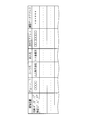
- FIG. 4 is a conceptual diagram showing an example of a management table stored in the database 45.
- FIG. 4A is an identification table that stores the imaging position and chain ID, and identifies the chain 10.
- FIG. 4B stores the imaging time and the degree of expansion in association with the imaging position, and individually describes the state of the chain 10. It is an individual table to grasp.
- the identification table includes an imaging position at which the chain 10 is imaged, a chain ID, a user name using the chain 10, a delivery destination to which the chain 10 has been delivered, a destination address indicating the address of the management computer 50, and an imaging.
- An imaging data address indicating a data storage location is stored.
- a chain ID, a user name, a destination, a destination address, and an imaging data address are stored in association with the imaging position.
- the individual table has an imaging time when the chain 10 is imaged, a degree of expansion of the chain 10, an exchange flag indicating whether it is time to replace the chain 10, and whether an abnormality has occurred in the chain 10.
- a warning flag indicating whether or not is stored. Note that the imaging time, the degree of expansion, the replacement flag, and the warning flag are associated with the imaging position. In the initial state, the replacement flag and the warning flag are each set to 0 (a value indicating that there is no replacement time and a value indicating that no abnormality has occurred).
- FIG. 5 is an explanatory diagram for explaining a first method and a second method for calculating the degree of extension of the chain 10.
- a first method for calculating the extension degree of the chain 10 will be described.
- the chain 10 is imaged so as to include three or more pins 72, 72,..., 72, and the image of the imaged chain 10 is binarized. Then, the positions of three adjacent pins 72, 72,..., 72 are extracted, the number of pixels between the pins is obtained, and the inter-pin distances P1 and P2 are obtained (see FIG. 5). As described above, the end of the pin 72 is coated with the paint for distinguishing the pin 72 from the surroundings, and the position of the pin 72 is reliably extracted.
- P1 and P2 are compared, and the long distance is set as the pitch of the inner link 81, and the short distance is set as the pitch of the outer link 71.
- the comparison is based on the fact that only the inner link 81 is viewed as being stretched due to wear of the pin 72 and the bushing 82.
- the difference between the pitch of the inner link 81 and the pitch of the outer link 71 is obtained, and the ratio of the difference to the pitch of the outer link 71 (the degree of extension of the chain 10) is obtained.
- the extension degree of the chain 10 is obtained by the following equation (a). ⁇ (P2-P1) / P1 ⁇ .100 (a)
- the chain 10 is imaged so as to include four or more pins 72, 72,..., 72, and the image of the imaged chain 10 is binarized. Then, the positions of four adjacent pins 72, 72,..., 72 are extracted, the number of pixels between the pins is obtained, and the inter-pin distances P1, P2, and P3 are obtained (see FIG. 5).
- correction coefficients ⁇ , ⁇ and ⁇ for multiplying the inter-pin distances P1, P2 and P3 are obtained.
- Condition (1) is based on considering the case where the chain 10 is imaged from an oblique direction.
- Condition (2) is that when four consecutive pins 72, 72, ..., 72 are imaged, P1 ⁇ ⁇ and P3 ⁇ ⁇ both indicate the length of the outer links 71, 71 Based on indicating the length of the links 81, 81.
- P2 ⁇ ⁇ and P1 ⁇ ⁇ or P3 ⁇ ⁇ are compared, and the longer distance is set as the pitch of the inner link 81, and the shorter distance is set as the pitch of the outer link 71.
- the comparison is based on the fact that only the inner link 81 is visually extended as the pin 72 and the bushing 82 wear.
- the difference between the pitch of the inner link 81 and the pitch of the outer link 71 is obtained, and the ratio of the difference to the pitch of the outer link 71 (the degree of extension of the chain 10) is obtained.
- the degree of expansion of the chain 10 is obtained by the following equation (b).
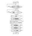
- FIG. 6 is a flowchart for explaining the extension degree calculation process based on the first method by the CPU 21 of the terminal device 20.
- the CPU 21 of the terminal device 20 determines whether or not a signal indicating the start of the extension degree calculation process is input by the operation of the operation unit 27 (step S1) and until a signal indicating the start of the extension degree calculation process is input. Wait (step S1: NO).
- the CPU 21 of the terminal device 20 determines whether or not image data is input from the image capturing unit 24 (step S2), and the image data (Step S2: NO).
- the CPU 21 of the terminal device 20 binarizes the captured image (step S3), extracts the positions of three consecutive pins, and between the pins. Distances P1 and P2 are calculated (step S4).
- the CPU 21 of the terminal device 20 compares P1 and P2, and obtains the pitch of the inner link 81 and the pitch of the outer link 71 (step S5). Then, the CPU 21 of the terminal device 20 calculates the extension degree of the chain 10 (step S6). At this time, the CPU 21 of the terminal device 20 calculates the extension degree of the chain 10 according to the above-described equation (a).
- the CPU 21 of the terminal device 20 transmits a command for displaying the calculated degree of expansion of the chain 10 to the display unit 26 (step S7).
- the display unit 26 that has received the command displays the degree of expansion of the chain 10.
- the CPU 21 of the terminal device 20 transmits the expansion degree of the chain 10, imaging data, the imaging time measured by the real-time clock 28, and the imaging position measured by the GPS 29 to the server 40 (step S8).
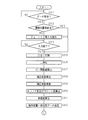
- FIG. 7 is a flowchart for explaining an extension degree calculation process based on the second method by the CPU 21 of the terminal device 20.
- the CPU 21 of the terminal device 20 determines whether or not a signal indicating the start of the extension degree calculation process has been input by the operation of the operation unit 27 (step S11), and until a signal indicating the start of the extension degree calculation process is input. Wait (step S11: NO).
- step S11: NO a signal indicating the start of the extension degree calculation process is input
- the CPU 21 of the terminal device 20 determines whether or not image data is input from the image capturing unit 24 (step S12), and the image data Is input until NO is input (step S12: NO).
- step S12 When imaging data is input from the imaging unit 24 (step S12: YES), the CPU 21 of the terminal device 20 binarizes the captured image (step S13), extracts the positions of four consecutive pins, and between the pins. The distances P1, P2, and P3 are calculated (step S14).
- the CPU 21 of the terminal device 20 calculates the correction coefficients ⁇ , ⁇ , and ⁇ by the method described above (step S15), and multiplies the inter-pin distances P1, P2, and P3 by the calculated correction coefficients ⁇ , ⁇ , and ⁇ , respectively (step S15). Step S16). Next, the CPU 21 of the terminal device 20 compares P2 ⁇ ⁇ with P1 ⁇ ⁇ or P3 ⁇ ⁇ to obtain the pitch of the inner link 81 and the pitch of the outer link 71 (step S17). Then, the CPU 21 of the terminal device 20 calculates the extension degree of the chain 10 (step S18). At this time, the CPU 21 of the terminal device 20 calculates the degree of expansion of the chain 10 using the above-described equation (a) or (b).
- the CPU 21 of the terminal device 20 transmits a command for displaying the calculated degree of expansion of the chain 10 to the display unit 26 (step S19).
- the display unit 26 that has received the command displays the degree of expansion of the chain 10.
- the CPU 21 of the terminal device 20 transmits the expansion degree of the chain 10, the imaging data, the imaging time measured by the real-time clock 28, and the imaging position measured by the GPS 29 to the server 40 (step S20).
- the CPU 21 of the terminal device 20 calculates the degree of expansion of the chain 10 based on the first method or the second method, and transmits the degree of expansion of the chain 10, imaging data, imaging time, and imaging position to the server 40. To do.
- the server 40 manages information regarding the chain 10.
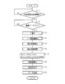
- FIG. 8 is a flowchart for explaining management processing by the CPU 41 of the server 40.
- the CPU 41 of the server 40 determines whether or not the expansion degree, imaging data, imaging time, and imaging position of the chain 10 are received from the terminal device 20 (step S21), and the expansion degree, imaging data, imaging time, and the imaging position of the chain 10 are determined. Wait until the imaging position is received (step S21: NO).
- the CPU 41 of the server 40 determines whether or not the received imaging position is already stored in the identification table (Ste S22).
- the CPU 41 of the server 40 transmits an instruction to input a chain ID or the like to the terminal device 20 (step S23).
- the received imaging position is not stored in the identification table, the chain ID, the user name, the delivery destination, and the delivery destination address (hereinafter referred to as a chain ID) are not stored in the identification table.
- the CPU 41 of the server 40 determines whether or not the input of the chain ID or the like from the terminal device 20 has been completed (step S24), and waits until the input of the chain ID or the like from the terminal device 20 is completed (step S24). : NO).
- the CPU 41 of the server 40 stores the imaging position, the chain ID, etc. in the database 45 (step S25).
- the CPU 41 of the server 40 stores the imaging position, the chain ID, and the like in the identification table, and stores an address indicating a storage area that is not used in the storage area of the database 45 as an imaging data address in the identification table.
- the CPU 41 of the server 40 stores the received imaging time and the degree of expansion of the chain 10 in an individual table corresponding to the imaging position, and stores the image data in the storage area of the database 45 indicated by the imaging data address.
- the CPU 41 of the server 40 adds the imaging time and the degree of expansion of the chain 10 to the individual table corresponding to the imaging position, and the imaging data address
- the image data is stored in the storage area of the database 45 indicated by (step S25).
- the imaging time and the degree of expansion of the chain 10 are added to the individual table and stored in the database 45 each time management processing is performed.
- the CPU 41 of the server 40 determines whether or not the latest extension stored in (added to) the individual table exceeds a predetermined value P (step S26).
- the predetermined value P is determined based on values affecting the physical state of the chain, such as the diameter of the pin 72, the inner diameter of the bush 82, the length of the chain 10, and the diameter of the sprocket, and is set in the RAM 43 in advance.
- the CPU 41 of the server 40 sets 1 (in the chain 10) in the replacement flag column corresponding to the latest expansion degree. A value indicating that it is time for replacement is set (step S27).
- the CPU 41 of the server 40 refers to the individual table, divides the difference between the latest extension degree and the previously stored extension degree by the difference in imaging time corresponding to both extension degrees, and the time change rate of the extension degree. Is calculated, and it is determined whether or not the calculated rate of change of time exceeds a predetermined value Q (step S28).
- the predetermined value Q is determined based on values that affect the physical state of the chain, such as the diameter of the pin 72, the inner diameter of the bush 82, the length of the chain 10, and the diameter of the sprocket, and is set in the RAM 43 in advance.
- the CPU 41 of the server 40 advances the process to step S28.
- step S28 YES
- the CPU 41 of the server 40 displays 1 (an abnormality has occurred in the chain 10) in the replacement flag column corresponding to the latest degree of expansion. Is set) (step S29). Then, the CPU 41 of the server 40 refers to the database 45 (step S30).
- step S28: NO the CPU 41 of the server 40 advances the processing to step S30.
- the CPU 41 of the server 40 transmits the degree of expansion of the chain 10, imaging data, position information, and imaging time to the management computer 50.
- the exchange flag corresponding to the latest imaging time 1
- a message prompting the exchange of the chain 10 is transmitted to the management computer 50
- the warning flag corresponding to the latest imaging time 1
- the chain 10 A message indicating that an abnormality has occurred is transmitted to the management computer 50 (step S31).
- the CPU 41 of the server 40 has an error in the message that prompts replacement of the chain 10 and the chain 10 is abnormal.
- a message indicating that the message has occurred may be further transmitted to the terminal device 20. In this case, it goes without saying that information for identifying the terminal device 20 is further received in step S21.
- two adjacent pin distances P1 and P2 are determined based on the images of three or more pins 72, 72,.
- the pitch of the outer link 71 and the pitch of the inner link 81 are calculated.
- the distances P1 and P2 between the two pins are calculated. Due to the structure of the chain 10, the dimension of the outer link 71 hardly changes before and after the use of the chain 10, but the dimension of the inner link 81 after use expands compared to before use.
- the long distance is the pitch of the inner link 81 and the short distance is the pitch of the outer link 71 among the calculated distances P1 and P2 between the pins.
- the pitch of the outer link 71 and the pitch of the inner link 81 before use are substantially equal to each other, the ratio of the difference between both pitches with respect to the pitch of the outer link 71 becomes the extension degree of the chain 10, and the distance between pins before use is determined in advance. Even without setting, the extension degree of the chain 10 can be measured.
- the operator or the user can surely recognize the degree of extension of the chain 10 via the display unit 26, and can immediately recognize whether or not the chain 10 is in the replacement period.
- the calculated degree of expansion of the chain 10 can be stored in the server 40 together with the imaging position and imaging time at which the chain 10 is imaged, the state of the chain 10 can be carefully managed, and appropriate measures for the chain 10 can be taken.
- the position where the chain 10 is installed (imaging position) and the management computer 50 (external device) used by the user of the chain 10 are associated with each other, and the measured degree of expansion of the chain 10 is transmitted from the server 40 to the management computer 50. Since the extension degree is reported to the user, the user can surely recognize the chain 10 that is in the replacement period.
- the server 40 can send a message to that effect to the management computer 50 to prompt the user to replace the chain 10 at the time of replacement.
- the server 40 sends a notification to that effect to the management computer 50 to notify the user that the chain 10 may be abnormal, It is possible to prompt the user to replace 10 or stop using the chain 10.
- the degree-of-extension measurement system corrects the three inter-pin distances P1 to P3, it may be configured to correct four or more inter-pin distances.
- the coating material is applied to the end of the pin 72 in the stretch degree measuring system according to the first embodiment, any configuration may be used as long as the pin 72 can be distinguished from the surroundings when the chain 10 is imaged. Instead of applying the paint, the end of the pin 72 may be mirror-finished.
- user authentication may be performed when the application program is stored (downloaded) from the server 40 into the ROM 22. Further, the application program may be stored in the ROM 22 in advance without downloading the application program from the server 40 to the ROM 22.
- the terminal device 20 transmits the imaging data of the chain 10 to the server 40 together with the imaging position and the imaging time. Then, the server 40 calculates the degree of chain expansion, returns the calculated degree of expansion to the terminal device 20, and displays the degree of expansion on the display unit 26 of the terminal device 20.
- FIG. 9 is a flowchart for explaining processing for displaying the degree of expansion of the chain 10 by the CPU 21 of the terminal device 20.
- the CPU 21 of the terminal device 20 determines whether or not a signal indicating the start of the extension degree calculation process has been input by operating the operation unit 27 (step S41), and until a signal indicating the start of the extension degree calculation process is input. Wait (step S41: NO).
- a signal indicating the start of the extension degree calculation process is input (step S41: YES)
- the CPU 21 of the terminal device 20 determines whether or not imaging data is input from the imaging unit 24 (step S42), and the imaging data Is input until NO is input (step S42: NO).
- step S42 When imaging data is input from the imaging unit 24 (step S42: YES), the CPU 21 of the terminal device 20 displays the imaging data, the imaging time measured with the real-time clock 28, and the imaging position measured with the GPS 29 with the server 40. (Step S43).
- the CPU 21 of the terminal device 20 determines whether or not data indicating the degree of expansion of the chain 10 is returned from the server 40 (step S44), and waits until data indicating the degree of expansion of the chain 10 is returned (step S44). S44: NO).
- the CPU 21 of the terminal device 20 displays the extension degree of the chain 10 on the display unit 26 (step S45).
- FIG. 10 and FIG. 11 are flowcharts for explaining the extension degree calculation processing and management processing by the CPU 41 of the server 40.
- the CPU 41 of the server 40 determines whether or not the imaging data, the imaging time and the imaging position are received from the terminal device 20 (step S51), and waits until the imaging data, the imaging time and the imaging position are received (step S51: NO).
- the CPU 41 of the server 40 determines whether or not the received imaging position is already stored in the identification table (step S52).
- the CPU 41 of the server 40 transmits an instruction to input a chain ID or the like to the terminal device 20 (step S53).
- the received imaging position is not stored in the identification table, the chain ID, the user name, the delivery destination, and the delivery destination address (hereinafter referred to as a chain ID) are not stored in the identification table.
- the CPU 41 of the server 40 determines whether or not the input of the chain ID or the like from the terminal device 20 has been completed (step S54), and waits until the input of the chain ID or the like from the terminal device 20 is completed (step S54). : NO).
- the CPU 41 of the server 40 stores the imaging position, the chain ID, and the like in the database 45 (step S55).
- the CPU 41 of the server 40 stores the imaging position, the chain ID, and the like in the identification table, and stores an address indicating a storage area that is not used in the storage area of the database 45 in the identification table as an imaging data address.
- the CPU 41 of the server 40 stores the received imaging time in an individual table corresponding to the imaging position, and stores the image data in the storage area of the database 45 indicated by the imaging data address.
- the CPU 41 of the server 40 binarizes the captured image (step S56), extracts the positions of four consecutive pins, and calculates inter-pin distances P1, P2, and P3 (step S57).
- the CPU 41 of the server 40 calculates the correction coefficients ⁇ , ⁇ , and ⁇ by the second method described above (step S58), and multiplies the inter-pin distances P1, P2, and P3 by the calculated correction coefficients ⁇ , ⁇ , and ⁇ , respectively. (Step S59). Next, the CPU 41 of the server 40 compares P2 ⁇ ⁇ with P1 ⁇ ⁇ or P3 ⁇ ⁇ to obtain the pitch of the inner link 81 and the pitch of the outer link 71 (step S60). Then, the CPU 41 of the server 40 calculates the extension degree of the chain 10 (step S61). At this time, the CPU 41 of the server 40 calculates the degree of expansion of the chain 10 using the above-described equation (a) or (b).
- the CPU 41 of the server 40 returns data indicating the calculated degree of expansion of the chain 10 to the terminal device 20 (step S62). Then, the CPU 41 of the server 40 refers to the database 45 and stores the calculated extension degree of the chain 10 in the extension degree column of the individual table corresponding to the imaging position and imaging time (step S63).
- the CPU 41 of the server 40 determines whether or not the latest degree of expansion stored in the individual table exceeds a predetermined value P (step S64).
- the predetermined value P is set in the RAM 43 in advance.
- the CPU 41 of the server 40 sets 1 (in the chain 10) in the replacement flag column corresponding to the latest expansion degree.
- a value indicating that it is time for replacement is set (step S65).
- the CPU 41 of the server 40 refers to the individual table, divides the difference between the latest extension degree and the previously stored extension degree by the difference in imaging time corresponding to both extension degrees, and the time change rate of the extension degree. Is calculated, and it is determined whether or not the calculated rate of change of time exceeds a predetermined value Q (step S66).
- the predetermined value Q is set in the RAM 43 in advance.
- the CPU 41 of the server 40 advances the process to step S66.
- step S66 YES
- the CPU 41 of the server 40 displays 1 (an abnormality has occurred in the chain 10) in the replacement flag column corresponding to the latest degree of expansion. Is set) (step S67). Then, the CPU 41 of the server 40 refers to the database 45 (step S68).
- step S66: NO the CPU 41 of the server 40 advances the process to step S68.
- the CPU 41 of the server 40 transmits the degree of expansion of the chain 10, imaging data, position information, and imaging time to the management computer 50.
- the exchange flag corresponding to the latest imaging time is 1, a message prompting the exchange of the chain 10 is transmitted to the management computer 50, and when the warning flag corresponding to the latest imaging time is 1, the chain 10 A message indicating that an abnormality has occurred is transmitted to the management computer 50 (step S69).
- the server 40 since the server 40 calculates the extension degree of the chain 10, the burden on the terminal device 20 is reduced.
- the degree-of-extension measuring system calculates the degree of extension of the chain 10 by the second method, but may be configured to calculate the degree of extension of the chain 10 by the first method.
- two adjacent pin distances P1 and P2 are calculated, respectively, and the pitch of the outer link 71 and the inner link 81 are calculated. Calculate the pitch. Then, the ratio of the difference between both pitches with respect to the pitch of the outer link 71 (the degree of extension of the chain 10) is calculated.
- the application program is stored in the ROM 42 by reading the application program stored in the recording medium 100, for example. Further, an application program may be stored when the ROM 42 is manufactured, or may be downloaded via a network.
- extension degree measuring system according to the first and second embodiments is an exemplification of the present invention, and the present invention can be implemented in various modifications within the scope of the matters described in the claims. It is.
Landscapes
- Engineering & Computer Science (AREA)
- General Engineering & Computer Science (AREA)
- Physics & Mathematics (AREA)
- General Physics & Mathematics (AREA)
- Mechanical Engineering (AREA)
- Length Measuring Devices By Optical Means (AREA)
Abstract
Description
以下本発明を実施の形態1に係る伸張度測定システムを示す図面に基づいて詳述する。図1はチェーンを略示する分解図である。
図中80は内リンクであり、内リンク80は、互いに対向する二つの内プレート81、81を備える。内プレート81は長円形の平板部材からなり、該平板部材の両端部に2つの穴を開設してある。一方の内プレート81の二つの穴に、円筒状の二つのブシュ82、82の一端部をしまりばめし、他方の内プレート81の二つの穴に、ブシュ82、82の他端部をしまりばめして、二つの内プレート81、81を連結している。各ブシュ82、82には環状のローラ85、85が回転自在に外嵌してある。
チェーン10は、図示しないスプロケットに掛け廻してある。チェーン10は、スプロケットの駆動によって図2の矢符にて示す方向に移動している。なおピン72の端部は外プレート71から適長突出しており、突出したピン72の端部には、チェーン10を撮像した場合にピン72と周囲とを識別することができるように、塗料が塗布してある。作業者は、チェーン10を端末装置(伸張度測定装置)20にて撮像する。
三つ以上並んだピン72、72、・・・、72を含むようにチェーン10を撮像し、撮像したチェーン10の画像を二値化する。そして、隣り合う三つのピン72、72、・・・、72の位置を抽出し、ピン間の画素数を求め、ピン間距離P1及びP2を求める(図5参照)。なお前述したようにピン72の端部には、ピン72と周囲と識別するための塗料が塗布してあり、ピン72の位置の抽出は確実に行われる。
{(P2-P1)/P1}・100・・・・(a)
{(P1・α-P2・β)/P2・β}・100・・・・(b)
またP1・α及びP3・γが外リンク71のピッチであり、P2・βが内リンク81のピッチである場合には、以下の(c)式によってチェーン10の伸張度が求められる。
{(P2・β-P1・α)/P1・α}・100・・・・(c)
なお上記(b)式、(c)式におけるP1・αはP3・γに置換することができる。
図6は、端末装置20のCPU21による第1方法に基づいた伸張度算出処理を説明するフローチャートである。
端末装置20のCPU21は、操作部27の操作によって伸張度算出処理の開始を示す信号が入力されたか否かを判定し(ステップS11)、伸張度算出処理の開始を示す信号が入力されるまで待機する(ステップS11:NO)。伸張度算出処理の開始を示す信号が入力された場合(ステップS11:YES)、端末装置20のCPU21は、撮像部24から撮像データが入力されたか否かを判定し(ステップS12)、撮像データが入力されるまで待機する(ステップS12:NO)。撮像部24から撮像データが入力された場合(ステップS12:YES)、端末装置20のCPU21は、撮像した画像を二値化し(ステップS13)、連続する四つのピンの位置を抽出してピン間距離P1、P2及びP3を算出する(ステップS14)。
以下本発明を実施の形態2に係る伸張度測定システムを示す図面に基づいて詳述する。実施の形態2に係る伸張度測定システムにあっては、端末装置20はチェーン10の撮像データを撮像位置及び撮像時刻と共にサーバ40に送信する。そしてサーバ40にてチェーンの伸張度を算出し、算出した伸張度を端末装置20に返信して、端末装置20の表示部26に伸張度を表示する。
サーバ40のCPU41は、端末装置20から撮像データ、撮像時刻及び撮像位置を受信したか否かを判定し(ステップS51)、撮像データ、撮像時刻及び撮像位置を受信するまで待機する(ステップS51:NO)。撮像データ、撮像時刻及び撮像位置を受信した場合(ステップS51:YES)、サーバ40のCPU41は、受信した撮像位置が既に識別テーブルに記憶されているか否かを判定する(ステップS52)。受信した撮像位置が識別テーブルに記憶されていない場合(ステップS52:NO)、サーバ40のCPU41は、チェーンIDなどを入力する指示を端末装置20に送信する(ステップS53)。なお受信した撮像位置が識別テーブルに記憶されていない場合、チェーンID、ユーザ名、納入先及び送付先アドレス(以下チェーンIDなどという)は識別テーブルに記憶されていない。
20 端末装置(伸張度測定装置)
21 CPU
22 ROM
23 RAM
24 撮像部
25 通信I/F
26 表示部(表示手段)
27 操作部
28 リアルタイムクロック
29 GPS
40 サーバ
41 CPU
42 ROM
43 RAM
44 通信I/F
45 データベース
50 管理コンピュータ(外部装置)
70 外リンク
72 ピン
80 内リンク
82 ブシュ
Claims (17)
- 内リンクの円筒状のブシュに外リンクのピンを内嵌させて複数の内リンク及び外リンクが交互に連結してあるチェーンを撮像して得られた画像に基づいて、前記チェーンの伸長度を測定する伸張度測定装置において、
三つ以上並んだ前記ピンの画像に基づいて、相隣るピン間距離をそれぞれ算出するピン間距離算出手段と、
算出した前記ピン間距離に基づいて前記外リンクのピッチ及び前記内リンクのピッチをそれぞれ算出するピッチ算出手段と、
算出した前記外リンクのピッチ及び前記内リンクのピッチに基づいて前記チェーンの伸張度を算出する伸張度算出手段と
を備えることを特徴とする伸張度測定装置。 - 前記伸張度算出手段は、前記外リンクのピッチに対する前記内リンクのピッチと前記外リンクのピッチとの差分の割合を算出するようにしてあることを特徴とする請求項1に記載の伸張度測定装置。
- 前記ピン間距離算出手段は、四つ以上並んだ前記ピンの画像に基づいて、前記ピン間距離を算出するようにしてあり、
前記ピッチ算出手段は、算出された前記外リンクのピッチ及び前記内リンクのピッチを線形関係にある係数によって補正するようにしてあり、
前記伸張度算出手段は、補正された前記外リンクのピッチ及び前記内リンクのピッチに基づいて前記チェーンの伸張度を算出するようにしてあること
を特徴とする請求項1又は2に記載の伸張度測定装置。 - 前記伸張度算出手段にて算出された前記伸張度を出力するようにしてあること
を特徴とする請求項1から3のいずれか一つに記載の伸張度測定装置。 - 請求項1から4に記載の伸張度測定装置は、前記チェーンを撮像した位置を測る測位手段と、前記チェーンを撮像した時刻を計る計時手段とを備えており、
前記伸張度測定装置と、
前記伸張度算定手段にて算出された前記伸張度、前記測位手段にて測った前記位置及び前記計時手段にて計った前記時刻を記憶するサーバと
を備えることを特徴とする伸張度測定システム。 - 前記サーバに記憶した前記伸張度を前記位置に対応する外部装置に送信するようにしてあることを特徴とする請求項5に記載の伸張度測定システム。
- 前記サーバに記憶した前記伸張度が所定値を超過している場合に、前記伸張度が所定値を超過したことを示す情報を前記サーバから前記外部装置に送信するようにしてあることを特徴とする請求項6に記載の伸張度測定システム。
- 前記サーバは、前記時刻及び算出された前記伸張度に基づいて前記伸張度の時間変化率を算出し、算出された前記時間変化率が所定値を超過している場合に、前記時間変化率が所定値を超過したことを示す情報を前記外部装置に送信するようにしてあることを特徴とする請求項6又は7に記載の伸張度測定システム。
- 内リンクの円筒状のブシュに外リンクのピンを内嵌させて複数の内リンク及び外リンクが交互に連結してあるチェーンを端末装置にて撮像し、撮像した前記チェーンの画像に基づいて、前記チェーンの伸長度をサーバにて算出する伸張度測定システムであって、
前記サーバは、
三つ以上並んだ前記ピンの画像に基づいて、相隣るピン間距離をそれぞれ算出するピン間距離算出手段と、
算出した前記ピン間距離に基づいて前記外リンクのピッチ及び前記内リンクのピッチをそれぞれ算出するピッチ算出手段と、
算出した前記外リンクのピッチ及び前記内リンクのピッチに基づいて前記チェーンの伸張度を算出する伸張度算出手段と
を備えることを特徴とする伸張度測定システム。 - 前記伸張度算出手段は、前記外リンクのピッチに対する前記内リンクのピッチと前記外リンクのピッチとの差分の割合を算出するようにしてあることを特徴とする請求項9に記載の伸張度測定システム。
- 前記ピン間距離算出手段は、四つ以上並んだ前記ピンの画像に基づいて、前記ピン間距離を算出するようにしてあり、
前記ピッチ算出手段は、算出された前記外リンクのピッチ及び前記内リンクのピッチを線形関係にある係数によって補正するようにしてあり、
前記伸張度算出手段は、補正された前記外リンクのピッチ及び前記内リンクのピッチに基づいて前記チェーンの伸張度を算出するようにしてあること
を特徴とする請求項9又は10に記載の伸張度測定システム。 - 前記端末装置は、前記伸張度算出手段にて算出された前記伸張度を出力するようにしてあること
を特徴とする請求項9から11のいずれか一つに記載の伸張度測定システム。 - 前記端末装置は、前記チェーンを撮像した位置を測る測位手段と、前記チェーンを撮像した時刻を計る計時手段とを備えており、
前記サーバは、算出された前記伸張度、前記測位手段にて測った前記位置及び前記計時手段にて計った前記時刻とを記憶するようにしてあること
を特徴とする請求項9から12のいずれか一つに記載の伸張度測定システム。 - 前記サーバは、記憶した前記伸張度を前記位置に対応する外部装置に送信するようにしてあること
を特徴とする請求項13に記載の伸張度測定システム。 - 前記サーバは、記憶した前記伸張度が所定値を超過している場合に、前記伸張度が所定値を超過したことを示す情報を前記外部装置に送信するようにしてあることを特徴とする請求項14に記載の伸張度測定システム。
- 前記サーバは、前記時刻及び算出された前記伸張度に基づいて前記伸張度の時間変化率を算出し、算出された前記時間変化率が所定値を超過している場合に、前記時間変化率が所定値を超過したことを示す情報を前記外部装置に送信するようにしてあることを特徴とする請求項14又は15に記載の伸張度測定システム。
- コンピュータを、内リンクの円筒状のブシュに外リンクのピンを内嵌させて複数の内リンク及び外リンクが交互に連結してあるチェーンを撮像して得られた画像に基づいて、前記チェーンの伸長度を算出する手段として機能させるコンピュータプログラムにおいて、
コンピュータを、
三つ以上並んだ前記ピンの画像に基づいて、相隣るピン間距離をそれぞれ算出するピン間距離算出手段、
算出した前記ピン間距離に基づいて前記外リンクのピッチ及び前記内リンクのピッチをそれぞれ算出するピッチ算出手段及び
算出した前記外リンクのピッチ及び前記内リンクのピッチに基づいて前記チェーンの伸張度を算出する伸張度算出手段
として機能させることを特徴とするコンピュータプログラム。
Priority Applications (2)
| Application Number | Priority Date | Filing Date | Title |
|---|---|---|---|
| CN201080054349.3A CN102713505B (zh) | 2009-11-30 | 2010-11-05 | 伸长度测量装置及伸长度测量系统 |
| US13/511,097 US9014482B2 (en) | 2009-11-30 | 2010-11-05 | Elongation measuring apparatus, elongation measurement system, and non-transitory medium |
Applications Claiming Priority (2)
| Application Number | Priority Date | Filing Date | Title |
|---|---|---|---|
| JP2009-272673 | 2009-11-30 | ||
| JP2009272673A JP5283608B2 (ja) | 2009-11-30 | 2009-11-30 | 伸張度測定装置、伸張度測定システム及びコンピュータプログラム |
Publications (1)
| Publication Number | Publication Date |
|---|---|
| WO2011065203A1 true WO2011065203A1 (ja) | 2011-06-03 |
Family
ID=44066306
Family Applications (1)
| Application Number | Title | Priority Date | Filing Date |
|---|---|---|---|
| PCT/JP2010/069697 Ceased WO2011065203A1 (ja) | 2009-11-30 | 2010-11-05 | 伸張度測定装置、伸張度測定システム及びコンピュータプログラム |
Country Status (4)
| Country | Link |
|---|---|
| US (1) | US9014482B2 (ja) |
| JP (1) | JP5283608B2 (ja) |
| CN (1) | CN102713505B (ja) |
| WO (1) | WO2011065203A1 (ja) |
Cited By (2)
| Publication number | Priority date | Publication date | Assignee | Title |
|---|---|---|---|---|
| WO2014062939A1 (en) | 2012-10-17 | 2014-04-24 | Caterpillar Inc. | Methods and systems for determining part wear based on digital image of part |
| JP2020033164A (ja) * | 2018-08-31 | 2020-03-05 | 中西金属工業株式会社 | チェーン設備監視システム |
Families Citing this family (16)
| Publication number | Priority date | Publication date | Assignee | Title |
|---|---|---|---|---|
| KR101610517B1 (ko) * | 2014-09-25 | 2016-04-07 | 현대자동차주식회사 | 동력체인 신율 검사 시스템 |
| FI128485B (en) * | 2015-07-06 | 2020-06-15 | Konecranes Oyj | Arrangement and method for checking the condition of the chain |
| EP3196625A1 (en) * | 2016-01-22 | 2017-07-26 | Renold PLC | Wear monitoring system by comparing wear between two types of sections |
| JP6170220B1 (ja) * | 2016-09-09 | 2017-07-26 | 東芝エレベータ株式会社 | 診断装置 |
| CN109983252B (zh) * | 2016-11-24 | 2022-03-22 | 三菱电机株式会社 | 链条伸长检测装置、链条伸长检测方法及乘客输送机 |
| CN110249202B (zh) | 2017-02-09 | 2021-07-20 | 莱特拉姆有限责任公司 | 用于测量带的装置和方法 |
| BE1025197B1 (nl) * | 2017-04-25 | 2018-12-10 | Etex Building Performance Nv | Inrichting voor het drogen van calciumsilicaathydraat gebaseerde platen |
| JP2019132668A (ja) * | 2018-01-30 | 2019-08-08 | 株式会社椿本チエイン | 伸長判定装置、伸長判定方法、及びコンピュータプログラム |
| WO2019168182A1 (ja) * | 2018-03-01 | 2019-09-06 | 大同工業株式会社 | 情報処理装置、情報処理方法、及びプログラム |
| KR102101824B1 (ko) * | 2019-05-03 | 2020-04-20 | 한국콘베어공업주식회사 | 마찰음을 이용한 롤러체인의 길이 추정 방법 |
| CN110906868A (zh) * | 2019-12-25 | 2020-03-24 | 上海诺司纬光电仪器有限公司 | 一种测距装置 |
| JP7136152B2 (ja) * | 2020-03-23 | 2022-09-13 | カシオ計算機株式会社 | 画像処理装置、画像処理方法、及び、プログラム |
| JP2022149862A (ja) * | 2021-03-25 | 2022-10-07 | カシオ計算機株式会社 | 画像処理装置、画像処理方法、及び、プログラム |
| CN117795283A (zh) * | 2021-07-16 | 2024-03-29 | 三菱电机株式会社 | 链条伸长检测装置 |
| CN115009772A (zh) * | 2022-07-21 | 2022-09-06 | 南京凯盛国际工程有限公司 | 一种板链斗式提升机的链板在线监测装置 |
| JP7622804B1 (ja) | 2023-12-18 | 2025-01-28 | いすゞ自動車株式会社 | チェーン測定システム |
Citations (7)
| Publication number | Priority date | Publication date | Assignee | Title |
|---|---|---|---|---|
| JPH10115676A (ja) * | 1996-10-15 | 1998-05-06 | Osaka Gas Co Ltd | マンロケーションシステムとこのマンロケーションシステムを用いた検査システム |
| JPH10288510A (ja) * | 1997-04-16 | 1998-10-27 | Tsubakimoto Chain Co | 距離測定方法、チェーン伸長度の検出方法及びチェーン伸長度の検出装置 |
| JPH10332342A (ja) * | 1997-05-30 | 1998-12-18 | Tsubakimoto Chain Co | チェーン伸長度の検出方法及び検出装置 |
| JP2000291748A (ja) * | 1999-04-07 | 2000-10-20 | Hitachi Building Systems Co Ltd | チェーンの伸長度診断装置 |
| JP2002007600A (ja) * | 2000-06-26 | 2002-01-11 | Hitachi Chem Co Ltd | 構造物の巡回管理方法、巡回管理支援装置、巡回管理支援システム、巡回管理用データ構造を記録した記録媒体、及び巡回管理支援プログラムを記録した記録媒体 |
| JP2008062733A (ja) * | 2006-09-06 | 2008-03-21 | Railway Technical Res Inst | 鉄道設備保守検査支援システム及びプログラム |
| JP2009074882A (ja) * | 2007-09-20 | 2009-04-09 | Mitsubishi Electric Building Techno Service Co Ltd | 手摺チェーン伸び率測定治具及びそれを用いたチェーン伸び率測定方法 |
Family Cites Families (13)
| Publication number | Priority date | Publication date | Assignee | Title |
|---|---|---|---|---|
| GB8800570D0 (en) * | 1988-01-12 | 1988-02-10 | Leicester Polytechnic | Measuring method |
| JPH082565Y2 (ja) * | 1992-03-31 | 1996-01-29 | 株式会社椿本チエイン | 無端移動体の伸び測定装置 |
| US5431273A (en) * | 1994-02-24 | 1995-07-11 | Sunkist Growers, Inc. | Apparatus and method for detecting a missing ejector in a sorting and conveying system |
| US5563392A (en) * | 1995-04-12 | 1996-10-08 | Patco Sales & Service, Inc. | Method and apparatus for monitoring wear of a continuous chain |
| JP3066412B2 (ja) | 1996-05-13 | 2000-07-17 | 株式会社椿本チエイン | チェーン伸長度の検出方法及び検出装置 |
| JPH10300426A (ja) | 1997-05-01 | 1998-11-13 | Tsubakimoto Chain Co | ローラチェーンの摩耗検出方法及び摩耗検出装置 |
| US20030132296A1 (en) * | 2002-01-17 | 2003-07-17 | Silver Edward M. | System and method for processing package delivery |
| ATE414853T1 (de) * | 2002-01-31 | 2008-12-15 | Frost Links Inc | Verschleissmessvorrichtung |
| GB2400090B (en) * | 2003-04-05 | 2006-04-19 | Renold Plc | Chain wear monitoring method and apparatus |
| MX2009002056A (es) * | 2006-08-24 | 2009-03-09 | Frost Links Inc | Dispositivo de supervision de desgaste de cadena. |
| US8238693B2 (en) * | 2007-08-16 | 2012-08-07 | Nokia Corporation | Apparatus, method and computer program product for tying information to features associated with captured media objects |
| US8285494B2 (en) * | 2009-10-20 | 2012-10-09 | Tibor Vozner | Conveyor chain monitoring system and method |
| CN201739453U (zh) * | 2010-05-25 | 2011-02-09 | 贾文良 | 自动调节的耐磨损链条张紧装置 |
-
2009
- 2009-11-30 JP JP2009272673A patent/JP5283608B2/ja not_active Expired - Fee Related
-
2010
- 2010-11-05 WO PCT/JP2010/069697 patent/WO2011065203A1/ja not_active Ceased
- 2010-11-05 US US13/511,097 patent/US9014482B2/en not_active Expired - Fee Related
- 2010-11-05 CN CN201080054349.3A patent/CN102713505B/zh not_active Expired - Fee Related
Patent Citations (7)
| Publication number | Priority date | Publication date | Assignee | Title |
|---|---|---|---|---|
| JPH10115676A (ja) * | 1996-10-15 | 1998-05-06 | Osaka Gas Co Ltd | マンロケーションシステムとこのマンロケーションシステムを用いた検査システム |
| JPH10288510A (ja) * | 1997-04-16 | 1998-10-27 | Tsubakimoto Chain Co | 距離測定方法、チェーン伸長度の検出方法及びチェーン伸長度の検出装置 |
| JPH10332342A (ja) * | 1997-05-30 | 1998-12-18 | Tsubakimoto Chain Co | チェーン伸長度の検出方法及び検出装置 |
| JP2000291748A (ja) * | 1999-04-07 | 2000-10-20 | Hitachi Building Systems Co Ltd | チェーンの伸長度診断装置 |
| JP2002007600A (ja) * | 2000-06-26 | 2002-01-11 | Hitachi Chem Co Ltd | 構造物の巡回管理方法、巡回管理支援装置、巡回管理支援システム、巡回管理用データ構造を記録した記録媒体、及び巡回管理支援プログラムを記録した記録媒体 |
| JP2008062733A (ja) * | 2006-09-06 | 2008-03-21 | Railway Technical Res Inst | 鉄道設備保守検査支援システム及びプログラム |
| JP2009074882A (ja) * | 2007-09-20 | 2009-04-09 | Mitsubishi Electric Building Techno Service Co Ltd | 手摺チェーン伸び率測定治具及びそれを用いたチェーン伸び率測定方法 |
Cited By (5)
| Publication number | Priority date | Publication date | Assignee | Title |
|---|---|---|---|---|
| WO2014062939A1 (en) | 2012-10-17 | 2014-04-24 | Caterpillar Inc. | Methods and systems for determining part wear based on digital image of part |
| EP2909608A4 (en) * | 2012-10-17 | 2016-06-08 | Caterpillar Inc | METHODS AND SYSTEMS FOR DETERMINING WEAR OF PARTS BASED ON DIGITAL IMAGE OF THE WORKPIECE |
| US9613413B2 (en) | 2012-10-17 | 2017-04-04 | Caterpillar Inc. | Methods and systems for determining part wear based on digital image of part |
| JP2020033164A (ja) * | 2018-08-31 | 2020-03-05 | 中西金属工業株式会社 | チェーン設備監視システム |
| JP7183633B2 (ja) | 2018-08-31 | 2022-12-06 | 中西金属工業株式会社 | チェーン設備監視システム |
Also Published As
| Publication number | Publication date |
|---|---|
| CN102713505B (zh) | 2015-03-04 |
| CN102713505A (zh) | 2012-10-03 |
| JP5283608B2 (ja) | 2013-09-04 |
| US20120269447A1 (en) | 2012-10-25 |
| JP2011117733A (ja) | 2011-06-16 |
| US9014482B2 (en) | 2015-04-21 |
Similar Documents
| Publication | Publication Date | Title |
|---|---|---|
| JP5283608B2 (ja) | 伸張度測定装置、伸張度測定システム及びコンピュータプログラム | |
| US10921520B2 (en) | Fusion splicing system, fusion splicer and method of determining rotation angle of optical fiber | |
| EP4151807B1 (de) | Verfahren und vorrichtung zum warten und/oder reparieren einer baumaschine | |
| JP5060888B2 (ja) | 装置の遠隔診断システム及び方法 | |
| TW200816066A (en) | Preventative maintenance update system | |
| CN112651649B (zh) | 一种数码印刷信息采集方法 | |
| JP2017119413A (ja) | 印刷装置、制御方法、及び、印刷システム | |
| WO2022133828A1 (zh) | 产品质量跟踪方法、装置、计算设备以及存储介质 | |
| CN113643252A (zh) | 一种车辆的螺丝扭力确定方法及扭力扳手 | |
| JP2018049516A (ja) | 調整作業支援システム | |
| CN100415459C (zh) | 机器人程序生成装置以及解析装置 | |
| JP2006175619A (ja) | 成形機監視装置及び方法 | |
| JP2000111318A (ja) | チェーンの寸法測定方法及びチェーンの寸法測定装置 | |
| CN110697490B (zh) | 一种电缆施工中长度缺陷的监测方法 | |
| JP6540061B2 (ja) | 情報処理装置、情報処理システム、情報処理方法及び情報処理用プログラム | |
| KR102821093B1 (ko) | 항만 안벽 구조물의 상태를 모니터링하기 위한 방법 및 시스템, 항만 안벽 구조물의 상태를 모니터링하기 위한 장치 | |
| JP2018110070A (ja) | コンタクト曲げ成形装置及びこれを用いたコンタクト成形方法 | |
| JP2019055547A (ja) | 画像形成装置 | |
| EP4303679A1 (en) | A system for reviewing an abnormal operating state of an equipment or an apparatus | |
| KR102790347B1 (ko) | 섬유 검사 장치 및 섬유 검사 방법 | |
| KR100750216B1 (ko) | 바디플라이반제품 오버랩량 자동제어장치가 구비된 성형드럼장치 | |
| US20240295470A1 (en) | System, apparatus, computer program product, and method for determining track pitch distance measurement | |
| JP4959155B2 (ja) | 外観検査誘導システム | |
| JP2025082482A (ja) | 鋼材の結束本数確認システムおよび鋼材の結束本数確認方法 | |
| CN121810271A (zh) | 裁切设备的维护方法、装置、设备及存储介质 |
Legal Events
| Date | Code | Title | Description |
|---|---|---|---|
| WWE | Wipo information: entry into national phase |
Ref document number: 201080054349.3 Country of ref document: CN |
|
| 121 | Ep: the epo has been informed by wipo that ep was designated in this application |
Ref document number: 10833050 Country of ref document: EP Kind code of ref document: A1 |
|
| WWE | Wipo information: entry into national phase |
Ref document number: 13511097 Country of ref document: US |
|
| NENP | Non-entry into the national phase |
Ref country code: DE |
|
| 122 | Ep: pct application non-entry in european phase |
Ref document number: 10833050 Country of ref document: EP Kind code of ref document: A1 |