WO2011055641A1 - 内視鏡装置及び内視鏡 - Google Patents
内視鏡装置及び内視鏡 Download PDFInfo
- Publication number
- WO2011055641A1 WO2011055641A1 PCT/JP2010/068725 JP2010068725W WO2011055641A1 WO 2011055641 A1 WO2011055641 A1 WO 2011055641A1 JP 2010068725 W JP2010068725 W JP 2010068725W WO 2011055641 A1 WO2011055641 A1 WO 2011055641A1
- Authority
- WO
- WIPO (PCT)
- Prior art keywords
- view
- image
- unit
- endoscope
- view observation
- Prior art date
Links
Images


Classifications
-
- G—PHYSICS
- G02—OPTICS
- G02B—OPTICAL ELEMENTS, SYSTEMS OR APPARATUS
- G02B23/00—Telescopes, e.g. binoculars; Periscopes; Instruments for viewing the inside of hollow bodies; Viewfinders; Optical aiming or sighting devices
- G02B23/24—Instruments or systems for viewing the inside of hollow bodies, e.g. fibrescopes
- G02B23/2407—Optical details
- G02B23/2423—Optical details of the distal end
- G02B23/243—Objectives for endoscopes
-
- A—HUMAN NECESSITIES
- A61—MEDICAL OR VETERINARY SCIENCE; HYGIENE
- A61B—DIAGNOSIS; SURGERY; IDENTIFICATION
- A61B1/00—Instruments for performing medical examinations of the interior of cavities or tubes of the body by visual or photographical inspection, e.g. endoscopes; Illuminating arrangements therefor
- A61B1/00064—Constructional details of the endoscope body
- A61B1/00071—Insertion part of the endoscope body
- A61B1/0008—Insertion part of the endoscope body characterised by distal tip features
- A61B1/00091—Nozzles
-
- A—HUMAN NECESSITIES
- A61—MEDICAL OR VETERINARY SCIENCE; HYGIENE
- A61B—DIAGNOSIS; SURGERY; IDENTIFICATION
- A61B1/00—Instruments for performing medical examinations of the interior of cavities or tubes of the body by visual or photographical inspection, e.g. endoscopes; Illuminating arrangements therefor
- A61B1/00163—Optical arrangements
- A61B1/00174—Optical arrangements characterised by the viewing angles
- A61B1/00177—Optical arrangements characterised by the viewing angles for 90 degrees side-viewing
-
- A—HUMAN NECESSITIES
- A61—MEDICAL OR VETERINARY SCIENCE; HYGIENE
- A61B—DIAGNOSIS; SURGERY; IDENTIFICATION
- A61B1/00—Instruments for performing medical examinations of the interior of cavities or tubes of the body by visual or photographical inspection, e.g. endoscopes; Illuminating arrangements therefor
- A61B1/00163—Optical arrangements
- A61B1/00174—Optical arrangements characterised by the viewing angles
- A61B1/00181—Optical arrangements characterised by the viewing angles for multiple fixed viewing angles
-
- A—HUMAN NECESSITIES
- A61—MEDICAL OR VETERINARY SCIENCE; HYGIENE
- A61B—DIAGNOSIS; SURGERY; IDENTIFICATION
- A61B1/00—Instruments for performing medical examinations of the interior of cavities or tubes of the body by visual or photographical inspection, e.g. endoscopes; Illuminating arrangements therefor
- A61B1/06—Instruments for performing medical examinations of the interior of cavities or tubes of the body by visual or photographical inspection, e.g. endoscopes; Illuminating arrangements therefor with illuminating arrangements
- A61B1/0615—Instruments for performing medical examinations of the interior of cavities or tubes of the body by visual or photographical inspection, e.g. endoscopes; Illuminating arrangements therefor with illuminating arrangements for radial illumination
-
- A—HUMAN NECESSITIES
- A61—MEDICAL OR VETERINARY SCIENCE; HYGIENE
- A61B—DIAGNOSIS; SURGERY; IDENTIFICATION
- A61B1/00—Instruments for performing medical examinations of the interior of cavities or tubes of the body by visual or photographical inspection, e.g. endoscopes; Illuminating arrangements therefor
- A61B1/06—Instruments for performing medical examinations of the interior of cavities or tubes of the body by visual or photographical inspection, e.g. endoscopes; Illuminating arrangements therefor with illuminating arrangements
- A61B1/0625—Instruments for performing medical examinations of the interior of cavities or tubes of the body by visual or photographical inspection, e.g. endoscopes; Illuminating arrangements therefor with illuminating arrangements for multiple fixed illumination angles
-
- A—HUMAN NECESSITIES
- A61—MEDICAL OR VETERINARY SCIENCE; HYGIENE
- A61B—DIAGNOSIS; SURGERY; IDENTIFICATION
- A61B1/00—Instruments for performing medical examinations of the interior of cavities or tubes of the body by visual or photographical inspection, e.g. endoscopes; Illuminating arrangements therefor
- A61B1/06—Instruments for performing medical examinations of the interior of cavities or tubes of the body by visual or photographical inspection, e.g. endoscopes; Illuminating arrangements therefor with illuminating arrangements
- A61B1/0655—Control therefor
-
- A—HUMAN NECESSITIES
- A61—MEDICAL OR VETERINARY SCIENCE; HYGIENE
- A61B—DIAGNOSIS; SURGERY; IDENTIFICATION
- A61B1/00—Instruments for performing medical examinations of the interior of cavities or tubes of the body by visual or photographical inspection, e.g. endoscopes; Illuminating arrangements therefor
- A61B1/12—Instruments for performing medical examinations of the interior of cavities or tubes of the body by visual or photographical inspection, e.g. endoscopes; Illuminating arrangements therefor with cooling or rinsing arrangements
- A61B1/126—Instruments for performing medical examinations of the interior of cavities or tubes of the body by visual or photographical inspection, e.g. endoscopes; Illuminating arrangements therefor with cooling or rinsing arrangements provided with means for cleaning in-use
-
- G—PHYSICS
- G02—OPTICS
- G02B—OPTICAL ELEMENTS, SYSTEMS OR APPARATUS
- G02B23/00—Telescopes, e.g. binoculars; Periscopes; Instruments for viewing the inside of hollow bodies; Viewfinders; Optical aiming or sighting devices
- G02B23/24—Instruments or systems for viewing the inside of hollow bodies, e.g. fibrescopes
- G02B23/2476—Non-optical details, e.g. housings, mountings, supports
-
- G—PHYSICS
- G02—OPTICS
- G02B—OPTICAL ELEMENTS, SYSTEMS OR APPARATUS
- G02B23/00—Telescopes, e.g. binoculars; Periscopes; Instruments for viewing the inside of hollow bodies; Viewfinders; Optical aiming or sighting devices
- G02B23/24—Instruments or systems for viewing the inside of hollow bodies, e.g. fibrescopes
- G02B23/2407—Optical details
- G02B23/2461—Illumination
- G02B23/2469—Illumination using optical fibres
Definitions
- the present invention relates to an endoscope apparatus and an endoscope capable of direct view and side view observation.
- endoscopes provided with illumination means and observation means on the distal end side of an insertion portion have been widely used in the medical field and others.
- an insertion portion of an endoscope is inserted into a tubular organ and used to inspect the inner wall.
- Endoscopes have been developed that have a side view field in which the lateral direction or circumferential direction is the observation field.
- the side view field of view is a range centering on a predetermined direction in the circumferential direction with 360 ° as the entire circumference. Therefore, in order to inspect the entire tubular inner wall, the insertion portion must be rotated in a wide range in the circumferential direction.
- Japanese Patent Application Laid-Open No. 2008-309860 as a second conventional example includes an optical system that is rotationally symmetric with respect to the central axis, and includes at least a direct-view optical path for imaging an object in the central axis direction and an annular optical element.
- a wide-angle side-viewing optical path (side-viewing observation unit) that forms an annular image in all directions (around the entire side) is formed outside the circular image of the direct-viewing optical path by reflecting twice.
- An optical system for the endoscope is disclosed.
- WO 2006/004083 as a third conventional example discloses an endoscope attachment that is attached to a distal end portion of an endoscope and includes a direct-view observation unit and a wide-angle side-view observation unit. .
- a structure is described in which illumination light is blocked from entering the side-view observation unit.
- a nozzle is provided for cleaning the adhering matter adhering to the observation window in the direct-view field of view and cleaning it.
- the nozzle enters the side view field and hinders good observation.
- a nozzle for removing deposits on the direct-viewing observation window or a conduit hereinafter, generically referred to as a nozzle
- the image of the nozzle becomes conspicuous in the side view visual field image. Since such a nozzle is not originally an object to be observed by the side-viewing observation window, it is desired not to appear in the side-view visual field image when an excellent side-view visual field image is to be formed.
- the short-distance side view field of view The brightness level of the image signal (video signal) is affected by the nozzle image appearing in the image, and the dimming function is degraded.
- the operator may perform the treatment by projecting the treatment tool from the channel. In this case, when the treatment tool is protruded, the treatment tool may appear in the side view visual field image as in the case of the nozzle, and the dimming function may be lowered.
- a mirror 171 for preventing illumination light from entering the side-view observation window is disclosed, but this mirror 171 blocks a part of the optical path of the illumination light. However, as is understood from the fact that it is disposed outside the side view field, it does not shield (shield) the side view field.
- the present invention has been made in view of the above points, and an endoscope apparatus and an endoscope that can prevent a protruding member such as a nozzle appearing in a side view field from appearing in an endoscope image such as a side view field image. The purpose is to provide a mirror.
- An endoscope apparatus includes an insertion portion that is inserted into an observation object; A side-view observation unit that is provided on the distal end side of the insertion unit and for acquiring a subject image of an observation object in the circumferential direction of the insertion unit; A direct-view observation unit for obtaining a subject image to be observed in the insertion direction of the insertion unit, provided on the distal end side of the side-view observation unit in the insertion unit; A projecting member that projects through the visual field of the side-view observation unit and protrudes toward the tip side from the side-view observation unit, Based on the subject image in the circumferential direction obtained from the side-view observation unit and the subject image in the insertion direction obtained from the direct-view observation unit, a side-view observation image and a direct-view observation image to be displayed as an observation image are displayed.
- the display of the object image to be observed in the range where the projecting member is located on the side-view visual field image is electrically performed.
- a shielding part for mechanical shielding It is characterized by providing.
- the endoscope of the present invention includes an insertion portion that is inserted into an observation object, A side-view observation unit that is provided on a distal end side of the insertion unit and that receives light from an observation object in a circumferential direction of the insertion unit to acquire a subject image; A direct-view observation unit for acquiring a subject image by being provided with light from an observation target in the insertion direction of the insertion unit, provided on the distal end side of the side-view observation unit in the insertion unit; A projecting member that projects through the visual field of the side-view observation unit and protrudes toward the tip side from the side-view observation unit, A shielding unit that is located in the field of view of the side-viewing unit and shields light incident on the side-viewing unit at least in a range through which the protruding member in the side-viewing field passes; It is characterized by providing.
- FIG. 1 is a perspective view showing an endoscope apparatus according to a first embodiment of the present invention.
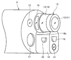
- FIG. 2 is a perspective view showing a configuration of a distal end portion of an insertion portion of the endoscope.
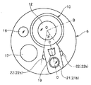
- FIG. 3 is a front view showing a configuration of a distal end portion of the insertion portion.
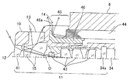
- FIG. 4 is a cross-sectional view showing the structure of the periphery of the objective optical system and the side-view illumination window along the OB cross section of FIG.
- FIG. 5 is a view showing a projecting member such as a nozzle part for a direct-viewing observation window disposed inside the shielding member along the CD section of FIG.
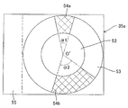
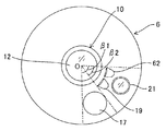
- FIG. 6 is a diagram illustrating an example of an endoscopic image according to the first embodiment.
- FIG. 1 is a perspective view showing an endoscope apparatus according to a first embodiment of the present invention.
- FIG. 2 is a perspective view showing a configuration of a distal end portion of an insertion portion of the endoscope
- FIG. 7 is a perspective view showing a configuration of a tip portion in the second embodiment of the present invention.
- FIG. 8 is a front view showing the configuration of the tip.
- FIG. 9 is a diagram illustrating an example of an endoscopic image according to the second embodiment.
- FIG. 10 is a perspective view showing the configuration of the tip in the third embodiment of the present invention.
- FIG. 11 is a front view showing the configuration of the tip.
- FIG. 12 is a diagram illustrating an example of an endoscopic image according to the third embodiment.
- FIG. 13 is a perspective view showing a configuration of a tip portion in a modification of the third embodiment.
- FIG. 14 is a front view showing the configuration of the distal end portion according to the fourth embodiment of the present invention.
- FIG. 14 is a front view showing the configuration of the distal end portion according to the fourth embodiment of the present invention.
- FIG. 15 is a block diagram showing a schematic configuration of the endoscope apparatus.
- FIG. 16A is a diagram showing an example of an endoscopic image when mask processing is turned off.
- FIG. 16B is a diagram showing an example of an endoscopic image when mask processing is turned on.
- FIG. 17 is a diagram showing an example of an endoscopic image when the mask processing corresponding to the arrangement information of the protruding members is set.
- an endoscope apparatus 1 As shown in FIG. 1, an endoscope apparatus 1 according to a first embodiment of the present invention has an endoscope 2 that performs an endoscopic examination.
- the endoscope 2 includes an operation unit 3 that an operator holds and operates, an elongated insertion unit 4 that is formed at the front end of the operation unit 3 and is inserted into an observation object such as a body cavity,
- the universal cord 5 has a base end extending from the side of the operation unit 3.
- the insertion portion 4 has a rigid distal end 6 provided at the distal end, a bendable bending portion 7 provided at the rear end of the distal end portion 6, and a long length provided at the rear end of the bending portion 7.
- the bending portion 7 includes a flexible tube portion 8 having flexibility.
- the bending portion 7 can be bent by a bending operation lever 9 provided in the operation portion 3.
- the distal end portion 6 of the insertion portion 4 is formed with a cylindrical portion 10 that protrudes in a cylindrical shape from a position deviated, for example, upward from the center of the distal end surface of the distal end portion 6.
- An objective optical system 11 (see FIG. 4) that serves both as a direct view and a side view for optical observation is provided at the tip of the cylindrical portion 10 to provide a direct view observation window 12 as a direct view observation unit, and a side view observation unit.
- a side-view observation window 13 is formed, and a side-view illumination window 14 is formed near the proximal end of the cylindrical portion 10.
- the side-view observation window 13 has a side-view visual field formed at a wide angle so as to cover the entire circumference in the side-surface direction along the substantially annular side-face direction in the cylindrical cylindrical portion 10,
- a mirror lens 15 serving as a reflection optical system for capturing the light from the subject in the side view field and acquiring it as a side view field image.
- a direct-view illumination window 16 that emits illumination light to illuminate and illuminates the observation target side corresponding to the direct-view field of view of the direct-view observation window 12 adjacent to the cylindrical portion 10 is inserted into the distal end surface of the distal end portion 6.
- a channel distal end opening 17 is provided as a distal end opening through which the treatment tool is projected.
- the support portion 18 protrudes from the distal end surface of the distal end portion 6 adjacent to, for example, the lower side position in the circumferential direction of the cylindrical portion 10. Provided.
- the support portion 18 is optically shielded so that the protruding member that constitutes the endoscope 2 that is not the original observation target and protrudes from the distal end surface appears in the side view field of view and is not acquired as a side view field of view image.
- a shielding portion 18a is provided.
- this support part 18 protrudes from the front end surface of the front-end
- the direct view illumination window 21 is supported (or held), and is shielded by the shielding portion 18a so as not to appear in the side view visual field image (the direct view observation window nozzle portion 19 and the direct view illumination window 21).
- the support portion 18 has a tip projecting from the side surface of the support portion 18 and opens so as to face the side view observation window 13, and is used for a side view observation window as a nozzle for cleaning the side view observation window 13.
- the nozzle part 22 for side view observation windows is provided in two places.
- the operation section 3 shown in FIG. 1 is fed so that a cleaning gas and a liquid can be selectively ejected from the direct-view observation window nozzle section 19 and the side-view observation window nozzle section 22, respectively.
- An air / liquid feeding operation button 24 is provided, and the air / liquid feeding operation button 24 can be operated to switch between air feeding and liquid feeding.
- the operation unit 3 is provided with a suction operation button 26 for sucking and collecting mucus or the like in the body cavity from the channel tip opening 17.
- the channel is formed by a tube (not shown) or the like disposed in the insertion portion 4 and communicates with a treatment instrument insertion port 27 provided near the front end of the operation portion 3.
- a connector 29 is provided at the end of the universal cord 5, and this connector 29 is connected to a light source device 31 of an endoscope.
- a base (not shown) serving as a connection end of a fluid conduit projecting from the tip of the connector 29 and a light guide base (not shown) serving as an illumination light supply end are detachable from the light source device 31.
- One end of the connection cable 33 is connected to the electrical contact portion provided on the side surface.
- the connector at the other end of the connection cable 33 is electrically connected to a signal processor for performing signal processing or image processing on the image sensor 34 mounted on the endoscope 2 or a video processor 32 as an image processing device.
- the video processor 32 supplies a drive signal for driving the image pickup device 34 (see FIG. 4) mounted on the distal end portion 6 of the endoscope 2, and an image pickup signal (image) output from the image pickup device 34 by the supply of the drive signal. Signal) is processed to generate a video signal.
- the video signal generated by the video processor 32 is output to a monitor 35 as a display device, and an image captured by the image sensor 34 is displayed on the display surface of the monitor 35 as an endoscopic image.
- Peripheral devices such as the light source device 31, the video processor 32, and the monitor 35 are arranged on a gantry 37 together with a keyboard 36 for inputting patient information and the like.
- Illumination light generated by the light source device 31 is transmitted from the universal cord 5 by a light guide passing through the operation unit 3 and the insertion unit 4, and the side-view illumination window 14 of the cylindrical unit 10 protruding from the distal end unit 6 and direct-view illumination.
- the window 16 and the direct-view illumination unit 19 are irradiated in a lateral direction and in an insertion direction so as to illuminate a subject such as an affected part.
- FIG. 4 shows the configuration of the periphery of the objective optical system 11 and the side-view illumination window 14 that serve both as a direct view and a side view, along the OB section of FIG.
- a front lens 41, a mirror lens 15, and a rear lens group 43 each having a rotationally symmetrical shape are arranged on an optical axis that coincides with the imaging center O along the central axis of the cylindrical portion 10 projecting from the distal end portion 6.
- An objective optical system 11 that forms an image on 34 is formed.
- a cover glass 34 a is provided on the front surface of the image sensor 34.
- the front lens 41 provided in the direct-viewing observation window 12 as a circular direct-viewing observation part at the tip of the cylindrical part 10 is a wide-angle direct view with the front side along the axial direction (insertion direction) of the insertion part 4 as an observation field. Create a field of view.
- the mirror lens 15 disposed immediately after the front lens 41 is composed of two cemented lenses. Light incident from the side is reflected twice by the cemented surface and the front surface and guided to the rear lens group 43 side. To do.
- the side view observation window 13 has a predetermined viewing angle with the optical axis in the side view direction being substantially the center with respect to the insertion portion major axis direction.
- a substantially annular observation field that covers the entire circumference in the circumferential direction of the insertion portion is formed.
- the direct-view observation window 12 protrudes from the distal end surface of the distal end portion 6 of the insertion portion 4 to the distal end side with respect to the side view observation window 13.
- the light incident on the front lens 41 that forms the direct-viewing observation window 12 from the subject side and the mirror lens 15 that forms the side-viewing observation window 13 on the subject side in the field of view. 1 shows a schematic path of a light ray incident from.
- a subject image is formed in a circular shape by light from the subject incident on the central side of the front lens 41 of the direct viewing observation window 12 and obtained as a direct viewing field image.
- the subject image is formed in an annular shape by the light from the subject incident in the field of view of the mirror lens 15 facing the side-view observation window 13 on the outer peripheral side of the direct-view field-of-view image. It will be acquired as a visual field image.
- a part of the annular-shaped side view visual field image is mechanically shielded by the shielding portion 18 a of the support portion 18.
- the distal end side of the light guide 44 as a light guide member for side view illumination is disposed on the peripheral side of the cylindrical portion 10, and the cylindrical portion 10 is centered on the position where the distal end surface of the light guide 44 faces.
- a light guide groove 45 extending in a belt shape is formed in the circumferential direction, and the light guide groove 45 is a reflection member 46 in which a concave reflection part 46 a is provided in a notch recess for forming the light guide groove 45. Is formed.
- the light guide grooves 45 formed by the light guide 44 and the reflecting member 46 are arranged at a plurality of locations along the circumferential direction of the cylindrical portion 10.
- the front end surface of the light guide 44 as the light guide member is positioned near the center position in the circumferential direction of each reflecting member 46 that forms the light guide groove 45 formed in a band shape along the circumferential direction of the cylindrical portion 10.
- the light emitted from the tip surface as the light emitting end surface of the light guide 44 is reflected by the reflecting portion 46a of the inner surface of the reflecting member 46 (the inner surface of the light guide groove 45), and the side direction in which the light guide groove 45 is provided.
- the illumination light is emitted at a wide angle.
- the side-view illumination window 14 that emits the side-view illumination light in a wide range in the side surface direction is formed by the light guide groove 45 formed by the plurality of light guides 44 and the reflection member 46. Therefore, the observation target side portion corresponding to the entire visual field in the side surface direction that can be observed through the side viewing observation window 13 can be illuminated by the illumination light emitted from the side viewing illumination window 14.
- the direct-view observation window nozzle portion 19 and the like disposed along the side-view observation window 13 are supported by the support portion 18 and side-view so that a good side-view image can be acquired. Shield against visual field.
- the support portion 18 has a substantially rectangular parallelepiped shape, and is formed so that the upper surface side portion of the rectangular parallelepiped shape contacts the side surface portion on the lower end side of the cylindrical portion 10.
- this support part 18 has the role which the shielding part 18a (refer FIG. 2) provided so as to oppose the side view observation window 13 in this support part 18 and to close this side view observation window 13 shields.
- the support 18 may be made of, for example, a metal such as stainless steel that forms the tip 6, or may be formed using a resin such as polysulfone, and the outer peripheral portion of the stainless steel may be formed of a resin. It may be covered.
- the shielding portion 18a facing the side-view observation window 13 is made of a material containing black paint, or the entire support portion 18 is black. You may make it become.
- the support unit 18 in this embodiment has the direct-viewing observation window nozzle unit 19.
- Such a protruding member is supported to increase its mechanical strength. For this reason, in this embodiment, it is set as the structure which has arrange
- FIG. In addition, it can also be set as the structure provided only with the function to shield like embodiment mentioned later.
- an air / liquid supply line 19 a is arranged inside the support portion 18, and the front end of the air / liquid supply line 19 a is bent in an L shape and is directed toward the direct-view observation window 12.
- the direct-viewing observation window nozzle 19 is formed by providing a direct-viewing observation window nozzle 19b.
- the direct-view observation window nozzle 19b changes the injection direction of the gas or liquid sent from the air / liquid supply pipe line 19a to a substantially right angle direction and emits the gas or liquid to the direct-view observation window 12 side.
- the body fluid or the like attached to the body 12 is removed from the direct-viewing observation window 12 by washing or the like, and a clean direct-viewing observation window 12 is obtained.
- a light guide 21a as a light guide member for illumination light is disposed inside the support portion 18 adjacent to the direct-viewing observation window nozzle portion 19, and an illumination lens 21b is disposed on the front end surface of the light guide 21a.
- a direct-view illumination window 21 is formed.
- the tip side portion of the light guide 21a and the illumination lens 21b are fixed in a tubular base 21c.
- the tip surface of the support portion 18 and the tip surface of the cylindrical portion 10 are formed so as to be substantially on the same plane.
- the side-view observation window nozzle portion 22 is also composed of an air / liquid feeding conduit (not shown) and a side-view observation window nozzle 22b that opens to the side view observation window 13 provided at the tip thereof.
- the side-view observation window nozzle 22b protrudes from the side surface of the support portion 18, the side-view visual field image is formed by the shielding portion 18a (see FIG. 2) formed so as to close the side-view observation window 13 in the support portion 18. It is shielded mechanically so as not to be acquired.
- the shielding portion 18a mechanically shields the angle ⁇ in the circumferential direction centered on the imaging center O, and the direct-viewing observation window nozzle portion 19 as a protruding member within the angle ⁇ , the direct-view illumination.
- a window 21 and a side-view observation window nozzle portion 22 are arranged.
- the endoscope 2 in the present embodiment having such a configuration has a subject in a side view field formed at a wide angle along the circumferential direction of the insertion unit 4 on the distal end side of the insertion unit 4 as a side view field image.
- the endoscope 2 includes a direct-viewing observation window nozzle portion 19 as a projecting member that passes through a side-viewing field of the side-viewing observation window 13 and projects to the tip side from the side-viewing observation window 13.
- FIG. 6 shows a display example when the subject image captured by the image sensor 34 is displayed on the display surface 35a of the monitor 35 using the endoscope 2 as an endoscopic image.
- a rectangular area 51 in FIG. 6 corresponds to a display area on the imaging surface of the imaging element 34.
- a central circular area in the rectangular area 51 is a display area 52 for a direct-view visual field image by the direct-view observation window 12, and an annular area outside the display area 52 is a display area 53 for a side-view visual field image by the side-view observation window 13.
- an area portion in which a part of the side view field is mechanically shielded from the shielding part 18a in the support part 18 is formed as a shielding area 54 in the side view field image.
- the shielding area 54 is an area corresponding to the angle ⁇ in FIG. 3 with the image center O ′ corresponding to the imaging center O in FIG. 3 as the center.
- the operator can smoothly inspect the tubular organ or the like by observing the endoscopic image.
- the endoscope 2 of the present embodiment as a constituent member of the endoscope 2 that appears in the side view field of the side view observation window 13 by the shielding portion 18a provided on the support portion 18 and is different from the original observation target.
- the light from the direct-viewing observation window nozzle portion 19, the direct-viewing illumination window 21, and the side-viewing observation window nozzle portion 22, which are protruding members, can be shielded from being acquired as a side-view visual field image.
- the light control signal for performing automatic light control can be generated from the image signal that is not affected by the protruding member. Automatic dimming can be used effectively without lowering.
- FIG. 7 is a perspective view showing a structure near the distal end of the insertion portion 4 in the endoscope according to the second embodiment of the present invention
- FIG. 8 is a front view thereof.
- the present embodiment basically has a configuration in which a part of the distal end portion 6 in the endoscope 2 of the first embodiment is deformed.
- the front end surface of the front end portion 6 supports, for example, a cylindrical portion 10 that protrudes in a cylindrical shape from the center position of the front end surface and a projecting member such as the direct-view observation window nozzle portion 19 and the side view of the side view observation window 13
- a support portion 18 provided with a shielding portion 18a that shields (shields) the light so as not to appear in the field of view is provided.
- the cylindrical portion 10 is provided with a direct view observation window 12, a side view observation window 13, and a side view illumination window 14.
- the outer diameter of the side-viewing illumination window 14 is set to the same outer diameter as that of the side-viewing observation window 13 is shown, but a different outer diameter may be used.
- the side-view illumination window 14 is configured to be able to illuminate the entire side periphery. Of course, the same configuration as in the first embodiment may be used.
- the channel tip opening 17 is open on the tip surface of the tip 6.
- the channel tip opening 17 is provided in the support 18 that forms the shielding part 18a. It has a configuration.
- the channel tip opening 17 communicates with a conduit 17b that forms a channel provided in the insertion portion 4 (including the tip 6) via a conduit 17a in the support portion 18.
- the cylindrical portion 10 is provided at a position eccentric from the center position of the tip portion 6, but in this embodiment, the cylindrical portion 10 is provided at the center position of the tip portion 6.
- the support portion 18 is provided in an orientation slightly deviated from the orientation directly below the cylindrical portion 10, but in this embodiment, the support portion 18 is provided in an orientation directly below the cylindrical portion 10. ing.
- the direct-view illumination window 16 is provided on the distal end surface of the distal end portion 6, but in this embodiment, the direct-view illumination window 16 is provided at a position closer to the upper portion. Yes.
- the shielding portion 18 a of the support portion 18 shields the optical axis of the objective optical system 11, that is, the imaging center O at the angle ⁇ in the circumferential direction.
- a direct viewing observation window nozzle 19, a direct viewing illumination window 21, a side viewing observation nozzle 22, and a channel tip opening 17 are provided on the support 18 that is within the angle ⁇ .
- Other configurations are the same as those of the first embodiment.
- the present embodiment basically has the same operational effects as the first embodiment, but also has different operational effects when a treatment tool is used.
- the protruded treatment tool when the surgeon protrudes the treatment tool from the channel tip opening portion 17, the protruded treatment tool appears in the side view field of the side view observation window 13, so that the treatment tool is viewed from the side. It will be in the state observed as a visual field image.
- the portion that appears in the side view field of the side observation window 13 in the duct 17a through which the treatment tool is inserted is shielded by the shielding portion 18a, so that the treatment tool is inserted. Does not appear in the side view image. For example, FIG.
- the distal end side of the treatment instrument 56 has a high function of reflecting light, and when entering the side view field in the immediate vicinity of the side view observation window 13, a high brightness image is obtained. Reduce the function of automatic dimming. In addition, because of the high luminance, there is a possibility of causing flare in the endoscopic image that becomes the observation image.
- the present embodiment even when the treatment instrument 56 is used, it is possible to obtain a good endoscopic image, and it can be used without reducing the automatic light control function.
- the endoscopic image displayed on the display surface 35a of the monitor 35 according to the present embodiment is as shown in FIG. Since FIG. 9 is similar to the case of FIG. 6, the same reference numerals as those of FIG. 6 are used.
- the present embodiment has the same effect as the first embodiment.
- an endoscopic image having a favorable side view visual field image can be obtained.
- the direct-viewing observation window nozzle portion that appears in the side-view visual field of the side-view observation window 13 by the shielding portion 18a by the support portion 18 as a protruding member different from the original observation target. 19. Since the direct-sight illumination window 21, the side-view observation window nozzle section 22, and the conduit 17a through which the treatment instrument 56 is inserted are shielded from being acquired as a side-view visual field image, a good side-view visual field image is generated. it can.
- the surgeon can smoothly inspect a tubular organ or the like by observing an endoscopic image having a good side view visual field image.
- the image signal of the image sensor 34 is used for automatic light control
- the image signal of the side view visual field image is an image signal that is not affected by the protruding member. Therefore, automatic dimming can be used effectively without reducing its function.
- the outer diameter of the support portion 18 may not be the same as the outer diameter of the distal end portion 6. Further, although the support portion 18 is provided at one location in the orientation on the lower side of the cylindrical portion 10, it may be provided at a plurality of locations.
- the distal end side of the treatment instrument 56 when the distal end side of the treatment instrument 56 is protruded further toward the distal end side so as to fall within the direct view field of the direct view observation window 12, the distal end side of the treatment instrument 56 can be observed by the direct view observation window 12. It becomes a state.
- the luminance level of the image signal of the direct-view visual field image is affected by the high-luminance portion on the distal end side of the treatment instrument 56, but at least the side-view visual field image is not affected by this. The effect can be reduced as compared with the case of being influenced by the image of the image.
- FIG. 10 is a perspective view showing a configuration near the distal end portion 6 of the insertion portion 4 of the endoscope according to the third embodiment of the present invention
- FIG. 11 is a front view thereof.
- the light from the protrusion member is within the side view field of the side view observation window 13.
- Shielding portions 61 a and 61 b are provided on the outer surface of the side-view observation window 13 so as not to enter.
- a cylindrical portion 10 having a cylindrical shape is provided at the central portion of the distal end surface of the distal end portion 6.
- the cylindrical portion 10 is provided with a direct view observation window 12, a side view observation window 13, and a side view illumination window 14 as in the second embodiment.
- the side-view observation window nozzle portion 62 and the direct-view illumination window 21 as projecting members are provided so as to project at the position on the top side of the cylindrical portion 10 on the distal end surface of the distal end portion 6.
- a nozzle for direct observation window 19 is provided as a protruding member at a position on the lower side so as to protrude.
- a channel tip opening 17 is provided on the tip surface of the tip 6 adjacent to the direct-view observation window nozzle 19. Further, the light from these projecting members does not enter the side field of view of the side viewing window 13 on the side surface on the upper side and the side surface on the lower side where the projecting member is provided in the side viewing window 13. Shielding parts 61a and 61b for shielding are provided.
- the shielding portions 61a and 61b can be configured by a film-like member formed by forming a black paint on the side-view observation window 13 in a film shape.
- the shielding portions 61a and 61b are not limited to this, and are other metals or the like having a high light-shielding function. May be formed in a film shape on the side-view observation window 13 by vapor deposition, or a black sheet or a sheet having a high light-shielding function may be adhered and attached to the side-view observation window 13.
- the shielding portions 61a and 61b shield the imaging center O at angles ⁇ 1 and ⁇ 2, respectively. Accordingly, light from the side-view observation window nozzle portion 62 and the direct-view illumination portion 63 is shielded by the shielding portion 61a, and light from the direct-view observation window nozzle portion 19 is shielded by the shielding portion 61b, and the side-view observation window 13 is shielded. It does not enter. Further, in the present embodiment, even when the treatment tool protrudes from the channel tip opening 17, the light from the treatment tool can be shielded by the shielding part 61b. Other configurations are the same as those in the first or second embodiment described above.
- FIG. 12 An endoscopic image displayed on the display surface 35a of the monitor 35 in the case of the present embodiment is as shown in FIG. As shown in FIG. 12, shielding areas 54a and 54b corresponding to the shielding parts 61a and 61b shown in FIG. 11 are formed in the side-view visual field image display area 53.
- the projecting member projecting from the distal end surface of the distal end portion 6 is shielded from being acquired as an image in the side-view observation window 13 in substantially the same manner as in the second embodiment.
- An endoscopic image having a visual field image can be acquired.
- the shielding part 61b can shield the flare. It can be used without degrading the function of light.
- the present embodiment by providing the film-like shielding portions 61a and 61b in the side-view observation window 13, the same effect as the second embodiment is realized at a low cost (excluding the support function). it can.
- FIG. 13 shows the configuration of the distal end portion 6 of the insertion portion 4 of the endoscope according to the first modification of the present embodiment.
- the tip end surface of the tip portion 6 extends along the side surface of the cylindrical portion 10 from the tip end of the side-view observation window 13.
- the structure is replaced with shielding plates 71a and 71b having a shielding function that protrude to the side. That is, the shielding plates 71a and 71b are disposed over the entire visual field from the rear side of the side view observation window 13 to the front side of the side view observation window 13 from the base end side to the distal end side of the side view observation window 13.
- the shielding plates 71a and 71b and the side-view observation window 13 may be bonded with an adhesive. Further, the inner surface of the shielding plates 71a and 71b on the side-viewing observation window 13 side may be frosted or coated with a dull paint. Further, as described above, a metal such as stainless steel having a high light shielding function or a resin such as polysulfone having a light shielding function may be used. This modification has substantially the same effect as that of the third embodiment.
- the shielding portion 61b may be formed so that light from the direct-viewing observation window nozzle portion 19 does not enter the side-viewing observation window 13.
- this modification when a treatment tool is used, it is affected by the treatment tool.
- a side-view observation window having a wider side view field. Can be realized.
- this second modification may be applied to the first modification.
- FIG. 14 shows the front view of the front-end
- a cylindrical portion 10 is provided at the center of the distal end surface of the distal end portion 6, and a channel distal end opening 17 is provided below the cylindrical portion 10.
- a direct view observation window nozzle portion 19 as a protruding member, a side view observation window nozzle portion 62, and a direct view illumination window 21.
- the projecting member and the channel tip opening 17 are arranged within an angle of ⁇ 1, for example, with the imaging center O as the center, and the projecting member alone is arranged within an angle of ⁇ 2 with the imaging center O as the center.
- a video processor 32D as an image processing apparatus to which the endoscope 2D including the distal end portion 6 is detachably connected performs signal processing on an image signal output from the image sensor 34 as shown in FIG.
- a signal processing unit 81 is built in, and a video signal as a display image signal generated by the signal processing unit 81 is output to the monitor 35.
- the video processor 32D is also detachably connected with an endoscope having an insertion portion 4 provided with a distal end portion different from the arrangement structure of the distal end portion 6 shown in FIG.
- the signal processing unit 81 electrically masks (shields) a portion corresponding to the protruding member with respect to the image signal portion by the side-view observation window 13 in the image signal of the image sensor 34 (referred to as mask processing).
- a mask processing unit 81a is provided.
- the mask processing unit 81 a performs mask processing corresponding to the control signal from the control unit 82.
- the endoscope 2D has an ID generation unit 83 that generates identification information (ID information) unique to the endoscope 2D. When the endoscope 2D is connected to the video processor 32D, the ID information Is input to an ID identification unit 84 provided in the video processor 32D.
- the ID identifying unit 84 sends the identified ID information to the control unit 82, and the control unit 82 generates a control signal corresponding to the ID information to control the mask processing of the mask processing unit 81a.
- the ID information includes arrangement information of the protruding member and the channel tip opening 17 appearing in the side visual field at the distal end portion 6 of the endoscope 2D, and the mask processing unit 81a is based on the ID information. Mask processing corresponding to the arrangement information of the unit 17 is performed.
- the video processor 32D (for example, in the mask processing unit 81a), from the ID information, the arrangement information of the protruding member and the channel tip opening 17 appearing in the side view field at the tip 6 of the endoscope 2D that generated the ID information
- An arrangement information recording means such as a lookup table to be read may be provided.
- the mask processing unit 81a performs at least mask processing corresponding to the placement information of the protruding member, and determines whether or not to perform mask processing corresponding to the placement information of the channel tip opening portion 17. May be selectable.
- control unit 82 is connected to an input device such as a keyboard 36, and an operator such as an operator can turn on / off the mask processing operation from the keyboard 36, a mask shape generated by the mask processing, a mask region, and the like. Instruction input can be performed, and the control unit 82 controls the operation of the mask processing unit 81a in response to the instruction input. Therefore, the input device such as the keyboard 36 has a function of a switching instruction means for instructing ON / OFF switching of the mask processing operation.
- the video processor 32D including the keyboard 36 has a function of switching means for switching ON / OFF of the mask processing operation.
- the input device as the switching instruction means may be a foot switch, a switch on the operation panel of the video processor, the scope switch 25, or the like in addition to the keyboard 36.
- the signal processing unit 81 outputs a video signal corresponding to the mask processing by the mask processing unit 81a to the monitor 35.
- the signal processing unit 81 calculates an average luminance corresponding to the brightness of the endoscope image from the masked video signal, and outputs a dimming signal for dimming to an appropriate brightness to the light source device 31.
- the signal processing unit 81 outputs, for example, a difference signal from a reference luminance value corresponding to appropriate brightness to the light source device 31 as a dimming signal.
- the light source device 31 adjusts the amount of light from a lamp 85 as a light source by a diaphragm 86 whose opening / closing amount is adjustable, condenses it with a lens 87, and supplies it to a light guide 88 as a light guide member for illumination light.
- the amount of illumination light supplied to the light guide 88 is automatically adjusted (automatic light control) by automatically adjusting the opening / closing amount of the diaphragm 86 based on the light control signal.
- the amount of illumination light supplied to the light guide 88 is adjusted so as to maintain the luminance value (luminance level) in the case of appropriate brightness.
- the opening / closing amount of the diaphragm 86 is controlled to be small by the dimming signal in that case.
- the brightness value is adjusted so as to maintain the brightness value.
- FIG. 16A shows an endoscopic image when the mask processing by the mask processing unit 81a is turned off.
- the endoscope image is displayed in the direct-view visual field image display region 52 and the side-view visual field image display region 53 in a state where the mask processing is not performed.
- FIG. 16B shows an endoscopic image when the ID generation unit 83 performs mask processing corresponding to the ID information.
- the display area portion in which the protruding member and the channel tip opening 17 are displayed in the display field 53 of the side view image corresponding to the arrangement information of the protruding member and the channel tip opening 17 is electrically
- the mask portion 89a is masked by the mask portion 89a, and the image of the area of the mask portion 89a becomes a non-image output region where no image is displayed (displayed).
- the image of the protruding member that appears in the side view field of the side view observation window 13 can be shielded by electrical signal processing so that it is not displayed on the endoscopic image.
- the endoscopic image displayed on the monitor 35 has the same effect as the case of shielding by the shielding portion provided on the endoscope side as in the first to third embodiments described above. Further, in the present embodiment, since the dimming signal can be generated from the video signal subjected to the mask processing, the dimming function for the case of the projecting member is originally used when the treatment tool is used. However, the dimming function can be used without degrading (the dimming function).
- the luminance level of the image signal (video signal) of the original image to be observed is the level of the nozzle image.
- the dimming function is lowered.
- the dimming signal is generated from the video signal obtained by masking the image of the protruding member in the side view visual field image, it is possible to prevent the dimming function from being deteriorated.
- the treatment tool is protruded from the channel tip opening portion 17, the same function as in the case of the protruding member is performed. This treatment tool can also be regarded as a protruding member.
- the surgeon can input an instruction from the keyboard 36 to perform mask processing corresponding to the arrangement information of only the protruding members.
- this instruction is input, as shown in FIG. 17, a non-image area can be formed by the mask portion 89b corresponding to the arrangement information of only the protruding members.
- the display area of the side view image can be widened. it can.
- the endoscope itself is an endoscope that does not have a shielding part function
- the mask processing unit 81a generates a mask unit subjected to mask processing according to the instruction input. Therefore, the mask portion desired by the surgeon is generated, and the surgeon can perform an endoscopic examination in an endoscopic image state in which the mask portion is formed.
- the region for forming the mask portion can be changed.
- embodiments configured by partially combining the above-described embodiments and the like also belong to the present invention.
- the fourth embodiment and the first to third embodiments may be combined. In this configuration, a case where the protruding member appearing on the side view visual field image is mechanically shielded on the endoscope side and a case where the projecting member is electrically shielded on the image processing device side are included.
- a shielding portion that is mechanically shielded by the shielding plates 71a and 71b provided in the endoscope is formed, but the shielding plates 71a and 71b are provided.
- an endoscope that is not it is electrically shielded on the image processing apparatus side.
- the image processing apparatus can be electrically shielded.
Abstract
内視鏡は、観察対象物内に挿入される挿入部の先端側に設けられ、挿入部の周方向及び挿入方向の観察対象の被写体像をそれぞれ取得するための側視観察部及び直視観察部と、側視観察部の視野内を通って、側視観察部よりも先端側に突出する突出部材と、側視観察部の視野内に位置し、突出部材が通る範囲において側視観察部に入射する光を遮蔽するする遮蔽部と、を備える。
Description
本発明は直視と側視の観察が可能な内視鏡装置及び内視鏡に関する。
近年、挿入部の先端側に照明手段及び観察手段を備えた内視鏡は医療用分野及びその他において広く用いられるようになっている。
内視鏡の挿入部を管状臓器内に挿入してその内壁の検査に使用される場合がある。このような場合の検査を行い易くするために、挿入部の軸方向(挿入方向)に沿った挿入部の前方側(先端側)を観察視野とする直視視野の他に、挿入部の側面となる側面方向又は周方向を観察視野とする側視視野を備えた内視鏡が開発されている。
例えば、第1の従来例としての特開2000-116598号公報には両方の視野を備えているが、側視視野は、360°を全周としてその周方向における所定の方向を中心とした範囲が観察できるのみであるため、管状の内壁全体を検査するためには、挿入部を周方向に広範囲に回転しなければならない。
内視鏡の挿入部を管状臓器内に挿入してその内壁の検査に使用される場合がある。このような場合の検査を行い易くするために、挿入部の軸方向(挿入方向)に沿った挿入部の前方側(先端側)を観察視野とする直視視野の他に、挿入部の側面となる側面方向又は周方向を観察視野とする側視視野を備えた内視鏡が開発されている。
例えば、第1の従来例としての特開2000-116598号公報には両方の視野を備えているが、側視視野は、360°を全周としてその周方向における所定の方向を中心とした範囲が観察できるのみであるため、管状の内壁全体を検査するためには、挿入部を周方向に広範囲に回転しなければならない。
このため、広範囲の回転を必要としないで、側方全周に近い広角の側視視野を備えた内視鏡が望まれる。
第2の従来例としての特開2008-309860号公報には、中心軸に対して回転対称な光学系を備え、中心軸方向の物体を撮像する直視光路と、円環状の光学素子内で少なくとも2回の反射をし、同一の撮像素子上に、直視光路の円形の映像の外側に全方位(側方全周)の円環状画像を形成する広角の側視光路(側視観察部)とを形成した内視鏡の光学系が開示されている。
また、第3の従来例としてのWO2006/004083号公報には、内視鏡の先端部に取り付けられ、直視観察部と広角の側視観察部とを備えた内視鏡アタッチメントが開示されている。
この第3の従来例においては、側視観察部に照明光が入らないように遮光する構造が記載されている。
第2又は第3の従来例のように、広角の側視観察部を形成した場合には、直視視野の観察窓に付着した付着物を洗浄等して清浄にするためのノズルを設けた場合、そのノズルが側視視野内に入り、良好な観察の妨げになってしまう欠点がある。
具体的には、直視観察窓の付着物を除去するためのノズル又はこのノズルに液体を通す管路(以下、ノズルで総称)は、広角の側視観察窓の側視視野内で、その側視観察窓に近い距離に配置しなければならないなるため、そのノズルの画像が側視視野画像に目立つようになってしまう。
このようなノズルは、本来、側視観察窓による観察対象でないため、良好な側視視野画像を形成しようとする場合には、側視視野画像に現れないようにすることが望まれる。
具体的には、直視観察窓の付着物を除去するためのノズル又はこのノズルに液体を通す管路(以下、ノズルで総称)は、広角の側視観察窓の側視視野内で、その側視観察窓に近い距離に配置しなければならないなるため、そのノズルの画像が側視視野画像に目立つようになってしまう。
このようなノズルは、本来、側視観察窓による観察対象でないため、良好な側視視野画像を形成しようとする場合には、側視視野画像に現れないようにすることが望まれる。
また、撮像した画像信号に基づく輝度レベルから照明光による光量を自動調整する調光機能を備えた内視鏡装置の場合には、本来の観察対象による画像の他に、近距離の側視視野画像に現れるノズルの画像によって、画像信号(映像信号)の輝度レベルが影響され、調光機能が低下する。
また、処置具を使用することができるように処置具が挿通されるチャンネルが設けられた内視鏡の場合には、術者は、チャンネルから処置具を突出して処置を行う場合がある。この場合には、処置具を突出した場合に、上記ノズルの場合のように、処置具が側視視野画像に現れて、調光機能を低下させる場合がある。
また、処置具を使用することができるように処置具が挿通されるチャンネルが設けられた内視鏡の場合には、術者は、チャンネルから処置具を突出して処置を行う場合がある。この場合には、処置具を突出した場合に、上記ノズルの場合のように、処置具が側視視野画像に現れて、調光機能を低下させる場合がある。
第2の従来例及び第3の従来例においては、ノズルを設けた場合、上記欠点を解消することが困難にある。
なお、第3の従来例における図2中においては、側視観察窓に照明光が入らないようにするミラー171が開示されているが、このミラー171は照明光の光路の一部を塞いでいるだけで、側視視野外に配置されていることから分かるように側視視野を遮光(遮蔽)するものでない。
本発明は上述した点に鑑みてなされたもので、側視視野内に現れるノズルのような突出部材を側視視野画像等の内視鏡画像に現れないようにできる内視鏡装置及び内視鏡を提供することを目的とする。
なお、第3の従来例における図2中においては、側視観察窓に照明光が入らないようにするミラー171が開示されているが、このミラー171は照明光の光路の一部を塞いでいるだけで、側視視野外に配置されていることから分かるように側視視野を遮光(遮蔽)するものでない。
本発明は上述した点に鑑みてなされたもので、側視視野内に現れるノズルのような突出部材を側視視野画像等の内視鏡画像に現れないようにできる内視鏡装置及び内視鏡を提供することを目的とする。
本発明の内視鏡装置は、観察対象物内に挿入される挿入部と、
前記挿入部の先端側に設けられ、該挿入部の周方向の観察対象の被写体像を取得するための側視観察部と、
前記挿入部における前記側視観察部よりも先端側に設けられ、前記挿入部の挿入方向の観察対象の被写体像を取得するための直視観察部と、
前記側視観察部の視野内を通って、前記側視観察部よりも先端側に突出する突出部材と、
前記側視観察部から得られた前記周方向の被写体像および前記直視観察部から得られた前記挿入方向の被写体像に基いて、観察画像として表示するための側視観察画像および直視観察画像を生成する画像処理装置と、前記画像処理装置により生成された前記観察画像が表示される際に、前記側視視野画像上の前記突出部材が位置する範囲における観察対象の被写体像の表示を電気的もしくは機械的に遮蔽するための遮蔽部と、
を備えることを特徴とする。
本発明の内視鏡は、観察対象物内に挿入される挿入部と、
前記挿入部の先端側に設けられ、該挿入部の周方向の観察対象からの光を入射させて被写体像を取得するための側視観察部と、
前記挿入部における前記側視観察部よりも先端側に設けられ、前記挿入部の挿入方向の観察対象からの光を入射させて被写体像を取得するための直視観察部と、
前記側視観察部の視野内を通って、前記側視観察部よりも先端側に突出する突出部材と、
前記側視観察部の視野内に位置し、少なくとも前記側視視野内の前記突出部材が通る範囲において前記側視観察部へ入射する光を遮蔽する遮蔽部と、
を備えることを特徴とする。
前記挿入部の先端側に設けられ、該挿入部の周方向の観察対象からの光を入射させて被写体像を取得するための側視観察部と、
前記挿入部における前記側視観察部よりも先端側に設けられ、前記挿入部の挿入方向の観察対象からの光を入射させて被写体像を取得するための直視観察部と、
前記側視観察部の視野内を通って、前記側視観察部よりも先端側に突出する突出部材と、
前記側視観察部の視野内に位置し、少なくとも前記側視視野内の前記突出部材が通る範囲において前記側視観察部へ入射する光を遮蔽する遮蔽部と、
を備えることを特徴とする。
以下、図面を参照して本発明の実施形態を説明する。
(第1の実施形態)
図1に示すように、本発明の第1の実施形態に係る内視鏡装置1は、内視鏡検査を行う内視鏡2を有する。この内視鏡2は、術者が把持して操作を行う操作部3と、この操作部3の前端に形成され、体腔内等の観察対象物内に挿入される細長の挿入部4と、操作部3の側部からその基端が延出されたユニバーサルコード5とにより構成されている。
又、挿入部4は、その先端に設けた硬質の先端部6と、この先端部6の後端に設けた湾曲自在の湾曲部7と、この湾曲部7の後端に設けた長尺で可撓性を有する可撓管部8とからなり、湾曲部7は操作部3に設けた湾曲操作レバー9により湾曲操作が可能である。
又、図2に示すように挿入部4の先端部6には、該先端部6の先端面の中央から例えば上方寄りに偏心した位置から円筒形状に突出する円筒部10が形成されている。この円筒部10の先端部に光学的観察を行うための直視及び側視を兼ねる対物光学系11(図4参照)を設けて直視観察部としての直視観察窓12と、側視観察部としての側視観察窓13とが形成され、かつ円筒部10の基端付近には側視照明窓14が形成されている。
側視観察窓13は、円筒形状の円筒部10における略環状の側面方向に沿って、側面方向の全周をカバーするように広角に形成された側視視野を有し、この側視視野内の被写体からの光を側視視野内に捉えて側視視野画像として取得するための反射光学系としてのミラーレンズ15を備える。
また、先端部6の先端面には、円筒部10に隣接して直視観察窓12の直視視野に対応する観察対象側に照明光を出射して照明する直視照明窓16と、チャンネル内に挿通された処置具を突出させる先端開口となるチャンネル先端開口部17とが設けられている。
また、本実施形態においては、良好な側視視野画像を生成するために、円筒部10の周方向における例えば下部側位置に隣接して、支持部18が先端部6の先端面から突出するように設けている。
また、先端部6の先端面には、円筒部10に隣接して直視観察窓12の直視視野に対応する観察対象側に照明光を出射して照明する直視照明窓16と、チャンネル内に挿通された処置具を突出させる先端開口となるチャンネル先端開口部17とが設けられている。
また、本実施形態においては、良好な側視視野画像を生成するために、円筒部10の周方向における例えば下部側位置に隣接して、支持部18が先端部6の先端面から突出するように設けている。
この支持部18は、先端面から突出される本来の観察対象ではない内視鏡2を構成する突出部材が、側視視野内に現れて、側視視野画像として取得されないように光学的に遮蔽する遮蔽部18aを設けている。
そして、この支持部18は、先端部6の先端面から突出し、側視視野内に現れる突出部材となる直視観察窓12を洗浄するノズルとしての直視観察窓用ノズル部19と、同様に突出部材となる直視照明窓21とを支持(又は保持)すると共に、側視視野画像に現れないように(直視観察窓用ノズル部19及び直視照明窓21を)遮蔽部18aにより遮蔽する。
また、この支持部18は、該支持部18の側面にその先端が突出し、側視観察窓13に対向するように開口して、側視観察窓13を洗浄するノズルとしての側視観察窓用ノズル部22を支持すると共に、側視視野画像に現れないように遮蔽する。なお、図3に示すように側視観察窓用ノズル部22は、2箇所に設けられている。
図1に示す操作部3には、上記直視観察窓用ノズル部19と側視観察窓用ノズル部22とからそれぞれ洗浄用の気体と液体とを選択的に射出させることができるように、送気送液操作ボタン24が設けてあり、この送気送液操作ボタン24の操作により送気と送液とを切り替えることができる。
また、この支持部18は、該支持部18の側面にその先端が突出し、側視観察窓13に対向するように開口して、側視観察窓13を洗浄するノズルとしての側視観察窓用ノズル部22を支持すると共に、側視視野画像に現れないように遮蔽する。なお、図3に示すように側視観察窓用ノズル部22は、2箇所に設けられている。
図1に示す操作部3には、上記直視観察窓用ノズル部19と側視観察窓用ノズル部22とからそれぞれ洗浄用の気体と液体とを選択的に射出させることができるように、送気送液操作ボタン24が設けてあり、この送気送液操作ボタン24の操作により送気と送液とを切り替えることができる。
なお、図1の図示例では1つの送気送液操作ボタン24を設けた例で示しているが、その機能を操作部3の頂部に設けたスコープスイッチ25に割り付けるようにしても良い。
また、操作部3には、チャンネル先端開口部17より体腔内の粘液等を、吸引して回収するための吸引操作ボタン26が配設されている。なお、チャンネルは、挿入部4内に配設された図示しないチューブ等によって形成され、操作部3の前端付近に設けた処置具挿入口27と連通している。
術者は、処置具による処置を行おうとする場合には、この処置具挿入口27から処置具を挿入し、その先端側をチャンネル先端開口部17から突出させることにより、処置具による治療のための処置を行うことができる。
また、操作部3には、チャンネル先端開口部17より体腔内の粘液等を、吸引して回収するための吸引操作ボタン26が配設されている。なお、チャンネルは、挿入部4内に配設された図示しないチューブ等によって形成され、操作部3の前端付近に設けた処置具挿入口27と連通している。
術者は、処置具による処置を行おうとする場合には、この処置具挿入口27から処置具を挿入し、その先端側をチャンネル先端開口部17から突出させることにより、処置具による治療のための処置を行うことができる。
又、ユニバーサルコード5の末端にはコネクタ29が設けられ、このコネクタ29は内視鏡の光源装置31に接続される。コネクタ29の先端から突出する流体管路の接続端部となる口金(図示せず)と、照明光の供給端部となる、ライトガイド口金(図示せず)とは光源装置31に着脱自在で接続され、又、側面に設けた電気接点部には接続ケーブル33の一端が接続される。
又、接続ケーブル33の他端のコネクタは、内視鏡2に搭載された撮像素子34に対する信号処理又は画像処理を行う信号処理装置又は画像処理装置としてのビデオプロセッサ32に電気的に接続される。
ビデオプロセッサ32は、内視鏡2の先端部6に搭載した撮像素子34(図4参照)を駆動する駆動信号を供給し、この駆動信号の供給により撮像素子34から出力される撮像信号(画像信号)に対して信号処理を行い、映像信号を生成する。
又、接続ケーブル33の他端のコネクタは、内視鏡2に搭載された撮像素子34に対する信号処理又は画像処理を行う信号処理装置又は画像処理装置としてのビデオプロセッサ32に電気的に接続される。
ビデオプロセッサ32は、内視鏡2の先端部6に搭載した撮像素子34(図4参照)を駆動する駆動信号を供給し、この駆動信号の供給により撮像素子34から出力される撮像信号(画像信号)に対して信号処理を行い、映像信号を生成する。
このビデオプロセッサ32により生成された映像信号は、表示装置としてのモニタ35に出力され、モニタ35の表示面には撮像素子34で撮像した画像が内視鏡画像として表示される。光源装置31、ビデオプロセッサ32、モニタ35等の周辺装置は、患者情報の入力等を行うキーボード36と共に、架台37に配置されている。
光源装置31で発生した照明光は、ユニバーサルコード5から操作部3及び挿入部4内を通したライトガイドにより伝送され、先端部6から突出する円筒部10の側視照明窓14と、直視照明窓16及び(支持部18に設けた)直視照明部19から、それぞれ側方と、挿入方向に拡開して照射され、患部等の被写体側を照明できるようにしている。
光源装置31で発生した照明光は、ユニバーサルコード5から操作部3及び挿入部4内を通したライトガイドにより伝送され、先端部6から突出する円筒部10の側視照明窓14と、直視照明窓16及び(支持部18に設けた)直視照明部19から、それぞれ側方と、挿入方向に拡開して照射され、患部等の被写体側を照明できるようにしている。
図4は図3のO-B断面により、直視及び側視を兼ねる対物光学系11及び側視照明窓14周辺部の構成を示す。
先端部6から突出する円筒部10の中心軸に沿った撮像中心Oと一致する光軸上に、それぞれ回転対称形状をした前レンズ41、ミラーレンズ15及び後レンズ群43が配置されて撮像素子34に結像する対物光学系11が形成されている。なお、撮像素子34の前面にはカバーガラス34aが設けられている。
円筒部10の先端の円形の直視観察部としての直視観察窓12に設けられた前レンズ41は、挿入部4の軸方向(挿入方向)に沿ったその前方側を観察視野とする広角の直視視野を形成する。
この前レンズ41の直後に配置されたミラーレンズ15は接合した2つのレンズにより構成され、側方から入射される光を接合面と前面とで2回反射して後レンズ群43側に導光する。
そして、側視観察窓13に設けられたミラーレンズ15により、この側視観察窓13は、挿入部長軸方向に対して側視方向の光軸を略中心とした所定の視野角度を有しつつ、挿入部周方向における全周をカバーする略円環状の観察視野を形成する。
図4から明らかなように、前記直視観察窓12は、側視観察窓13よりも挿入部4の先端部6の先端面から先端側に突出している。
なお、図4では、直視観察窓12を形成する前レンズ41に、その視野内の被写体側から入射される光線と、側視観察窓13を形成するミラーレンズ15に、その視野内の被写体側から入射される光線の概略の経路を示している。
図4から明らかなように、前記直視観察窓12は、側視観察窓13よりも挿入部4の先端部6の先端面から先端側に突出している。
なお、図4では、直視観察窓12を形成する前レンズ41に、その視野内の被写体側から入射される光線と、側視観察窓13を形成するミラーレンズ15に、その視野内の被写体側から入射される光線の概略の経路を示している。
そして、撮像素子34の撮像面には、その中央側に直視観察窓12の前レンズ41の視野内に入射される被写体からの光により被写体像が円形に結像されて、直視視野画像として取得されることになる。また、その直視視野画像の外周側に側視観察窓13に臨むミラーレンズ15の視野内に入射される被写体からの光により被写体像が円環形状に結像されて、円環形状の側視視野画像として取得されることになる。
但し、本実施形態においては、後述するように円環形状の側視視野画像における一部を支持部18の遮蔽部18aによりメカニカルに遮蔽する。
また、円筒部10の周辺側には側視照明用の導光部材としてのライトガイド44の先端側が配置され、このライトガイド44の先端面が臨む位置には、その位置を中心として円筒部10の周方向に帯状に延びる導光溝45が形成されており、この導光溝45は、導光溝45を形成するための切り欠き凹部内に凹面形状の反射部46aを設けた反射部材46を配置して形成される。
但し、本実施形態においては、後述するように円環形状の側視視野画像における一部を支持部18の遮蔽部18aによりメカニカルに遮蔽する。
また、円筒部10の周辺側には側視照明用の導光部材としてのライトガイド44の先端側が配置され、このライトガイド44の先端面が臨む位置には、その位置を中心として円筒部10の周方向に帯状に延びる導光溝45が形成されており、この導光溝45は、導光溝45を形成するための切り欠き凹部内に凹面形状の反射部46aを設けた反射部材46を配置して形成される。
ライトガイド44、反射部材46により形成される導光溝45は、円筒部10の周方向に沿って、複数箇所に配置されている。この場合、円筒部10の周方向に沿って帯形状に形成された導光溝45を構成する各反射部材46における周方向の中央位置付近に導光部材としてのライトガイド44の先端面が位置する。
そして、ライトガイド44の出射端面としての先端面から出射された光を反射部材46の内面(導光溝45の内面)の反射部46aで反射して、導光溝45が設けられた側面方向に照明光を広角で出射する。
そして、複数のライトガイド44及び反射部材46により形成される導光溝45により、側面方向の広範囲に側視照明光を出射する側視照明窓14を形成する。従って、側視照明窓14から出射される照明光により、側視観察窓13で観察可能となる側面方向の全周の視野に対応する観察対象側部分を照明することができる。
そして、ライトガイド44の出射端面としての先端面から出射された光を反射部材46の内面(導光溝45の内面)の反射部46aで反射して、導光溝45が設けられた側面方向に照明光を広角で出射する。
そして、複数のライトガイド44及び反射部材46により形成される導光溝45により、側面方向の広範囲に側視照明光を出射する側視照明窓14を形成する。従って、側視照明窓14から出射される照明光により、側視観察窓13で観察可能となる側面方向の全周の視野に対応する観察対象側部分を照明することができる。
また、本実施形態においては、良好な側視視野画像を取得できるように、側視観察窓13に沿って配設された直視観察窓用ノズル部19等を支持部18で支持すると共に側視視野に対して遮蔽する。
図2及び図3に示すように支持部18は、略直方体形状であり、この直方体形状の上面側部分が円筒部10下端側の側面部分に当接するように形成されている。
そして、この支持部18は、該支持部18における側視観察窓13に対向して、該側視観察窓13を塞ぐように設けた遮蔽部18a(図2参照)が、遮蔽する役割を持つ。この支持部18は、例えば先端部6を形成するステンレススチール等の金属製であっても良いし、ポリサルフォン等の樹脂を用いて形成しても良いし、上記ステンレススチールの外周側部分を樹脂で覆うようにしても良い。
図2及び図3に示すように支持部18は、略直方体形状であり、この直方体形状の上面側部分が円筒部10下端側の側面部分に当接するように形成されている。
そして、この支持部18は、該支持部18における側視観察窓13に対向して、該側視観察窓13を塞ぐように設けた遮蔽部18a(図2参照)が、遮蔽する役割を持つ。この支持部18は、例えば先端部6を形成するステンレススチール等の金属製であっても良いし、ポリサルフォン等の樹脂を用いて形成しても良いし、上記ステンレススチールの外周側部分を樹脂で覆うようにしても良い。
また、ポリサルフォン等の樹脂の場合には、光を遮蔽する機能を大きくするために、例えば側視観察窓13に臨む遮蔽部18a部分を黒色の塗料を含む材質にしたり、支持部18全体が黒色となるようにしても良い。
本実施形態における支持部18は、直視観察窓用ノズル部19等の突出部材が側視観察窓13の側部視野内に現れないように遮蔽する機能の他に、直視観察窓用ノズル部19等の突出部材を支持してその機械的強度を大きくしている。
このため、本実施形態においては、支持部18内を通して直視観察窓用ノズル部19等を配置した構成にしている。なお、後述する実施形態のように、遮蔽する機能のみを備えた構成にすることもできる。
本実施形態における支持部18は、直視観察窓用ノズル部19等の突出部材が側視観察窓13の側部視野内に現れないように遮蔽する機能の他に、直視観察窓用ノズル部19等の突出部材を支持してその機械的強度を大きくしている。
このため、本実施形態においては、支持部18内を通して直視観察窓用ノズル部19等を配置した構成にしている。なお、後述する実施形態のように、遮蔽する機能のみを備えた構成にすることもできる。
支持部18内部には、図5に示すように送気送液管路19aが配置され、この送気送液管路19aの先端にはL字状に屈曲して直視観察窓12側の方向に開口する直視観察窓用ノズル19bを設けて直視観察窓用ノズル部19が形成されている。
そして、この直視観察窓用ノズル19bは、送気送液管路19a側から送られた気体又は液体の射出方向を略直角方向に変え、直視観察窓12側に射出させることにより、直視観察窓12に付着した体液等の付着物を洗い流す等して、直視観察窓12から除去し、清浄な直視観察窓12の状態にする。
また、支持部18内部には、この直視観察窓用ノズル部19に隣接して照明光の導光部材としてのライトガイド21aが配置され、このライトガイド21aの先端面には照明レンズ21bを配置して、直視照明窓21を形成している。なお、ライトガイド21aの先端側部分及び照明レンズ21bは、管状の口金21c内に固定されている。
そして、この直視観察窓用ノズル19bは、送気送液管路19a側から送られた気体又は液体の射出方向を略直角方向に変え、直視観察窓12側に射出させることにより、直視観察窓12に付着した体液等の付着物を洗い流す等して、直視観察窓12から除去し、清浄な直視観察窓12の状態にする。
また、支持部18内部には、この直視観察窓用ノズル部19に隣接して照明光の導光部材としてのライトガイド21aが配置され、このライトガイド21aの先端面には照明レンズ21bを配置して、直視照明窓21を形成している。なお、ライトガイド21aの先端側部分及び照明レンズ21bは、管状の口金21c内に固定されている。
ライトガイド21aの先端面から出射される光をこの照明レンズ21bを経て直視照明窓21からその前方側に照明光として出射し、直視観察窓12の直視視野側の被写体を照明する。なお、支持部18の先端面と円筒部10の先端面とは実質的に同一面上に位置するように形成されている。
側視観察窓用ノズル部22も、図示しない送気送液管路とその先端に設けた側視観察窓13側に開口する側視観察窓用ノズル22bとから構成される。側視観察窓用ノズル22bは、支持部18の側面から突出しているが、支持部18における側視観察窓13を塞ぐように形成された遮蔽部18a(図2参照)により、側視視野画像として取得されないようにメカニカルに遮蔽される。
側視観察窓用ノズル部22も、図示しない送気送液管路とその先端に設けた側視観察窓13側に開口する側視観察窓用ノズル22bとから構成される。側視観察窓用ノズル22bは、支持部18の側面から突出しているが、支持部18における側視観察窓13を塞ぐように形成された遮蔽部18a(図2参照)により、側視視野画像として取得されないようにメカニカルに遮蔽される。
なお遮蔽部18aは、図3に示すように撮像中心Oを中心とした周方向におけるαの角度をメカニカルに遮蔽し、この角度α以内に突出部材としての直視観察窓用ノズル部19、直視照明窓21及び側視観察窓用ノズル部22が配置されている。
このような構成の本実施形態における内視鏡2は、挿入部4の先端側における、該挿入部4の周方向に沿って広角に形成された側視視野内の被写体を側視視野画像として取得するための側視観察部としての側視観察窓13と、挿入部4における前記側視観察窓13よりも先端側に設けられ、挿入部4の軸方向に沿った直視視野内の被写体を直視視野画像として取得するための直視観察部としての直視観察窓12と、を備える。
さらに、この内視鏡2は、前記側視観察窓13による側視視野内を通って、前記側視観察窓13よりも先端側に突出する突出部材としての直視観察窓用ノズル部19、直視照明窓21及び側視観察窓用ノズル部22と、前記側視視野内における少なくとも前記突出部材が通る範囲(所定の範囲)からの光が前記側視視野(または側視観察部)に入射するのを遮蔽する遮蔽部18aと、を備えることを特徴とする。
この内視鏡2を用いて、撮像素子34により撮像した被写体画像を、内視鏡画像としてモニタ35の表示面35aに表示した場合の表示例を図6に示す。
図6における矩形領域51は、撮像素子34の撮像面の表示領域に対応する。この矩形領域51における中央の円形領域が直視観察窓12による直視視野画像の表示領域52となり、この表示領域52の外側の環状領域が側視観察窓13による側視視野画像の表示領域53となる。
また、支持部18における遮蔽部18aより側視視野の一部をメカニカルに遮蔽した領域部分が側視視野画像における遮蔽領域54として形成される。この遮蔽領域54は、図3の撮像中心Oに対応する画像中心O′を中心として図3の角度αに対応する領域となる。
図6における矩形領域51は、撮像素子34の撮像面の表示領域に対応する。この矩形領域51における中央の円形領域が直視観察窓12による直視視野画像の表示領域52となり、この表示領域52の外側の環状領域が側視観察窓13による側視視野画像の表示領域53となる。
また、支持部18における遮蔽部18aより側視視野の一部をメカニカルに遮蔽した領域部分が側視視野画像における遮蔽領域54として形成される。この遮蔽領域54は、図3の撮像中心Oに対応する画像中心O′を中心として図3の角度αに対応する領域となる。
そして、術者は、内視鏡画像を観察することにより、管状臓器等の検査を円滑に行うことができるようにしている。
本実施形態の内視鏡2によれば、支持部18に設けた遮蔽部18aにより側視観察窓13の側視視野内に現れる、本来の観察対象とは異なる内視鏡2の構成部材としての突出部材である直視観察窓用ノズル部19、直視照明窓21、側視観察窓用ノズル部22からの光を側視視野画像として取得されないように遮蔽できる。そして、本実施形態の内視鏡2によれば、本来の観察対象とは異なる突出部材を遮蔽して、本来の観察対象に対する側視視野画像を取得できる。
また、本実施形態によれば、撮像素子34の画像信号を自動調光に利用した場合にも、自動調光を行う調光信号は、突出部材に影響されない画像信号から生成できるため、その機能が低下することなく自動調光を有効に利用できる。
(第2の実施形態)
次に本発明の第2の実施形態を説明する。図7は、本発明の第2の実施形態の内視鏡における挿入部4の先端付近の構造を斜視図で示し、図8は正面図で示す。
本実施形態は、基本的には第1の実施形態の内視鏡2における先端部6の一部を変形した構成となる。先端部6の先端面には、例えば先端面の中央位置から円筒形状に突出する円筒部10と、直視観察窓用ノズル部19等の突出部材を支持すると共に、側視観察窓13の側視視野内に現れないように遮蔽(遮光)する遮蔽部18aを設けた支持部18とが設けられている。
第1の実施形態と同様に、円筒部10には、直視観察窓12、側視観察窓13、側視照明窓14とが設けられている。なお、本実施形態においては、側視照明窓14の外径を側視観察窓13側と同じ外径にした例を示しているが、異なる外径にしても良い。また、本実施形態においては、側視照明窓14は、側方全周を照明可能とする構成にしている。勿論、第1の実施形態と同様の構成でも良い。
第1の実施形態においては、先端部6の先端面にチャンネル先端開口部17が開口していたが、本実施形態においては、チャンネル先端開口部17を遮蔽部18aを形成する支持部18に設けた構成にしている。
このチャンネル先端開口部17は、支持部18内の管路17aを介して、(先端部6を含む)挿入部4内に設けられているチャンネルを形成する管路17bと連通している。
また、第1の実施形態においては、円筒部10を先端部6の中心位置から偏心した位置に設けていたが、本実施形態においては円筒部10を先端部6の中心位置に設けている。
また、第1の実施形態においては、円筒部10の真下の方位から若干ずれた方位に支持部18を設けていたが、本実施形態においては円筒部10の真下の方位に支持部18を設けている。
このチャンネル先端開口部17は、支持部18内の管路17aを介して、(先端部6を含む)挿入部4内に設けられているチャンネルを形成する管路17bと連通している。
また、第1の実施形態においては、円筒部10を先端部6の中心位置から偏心した位置に設けていたが、本実施形態においては円筒部10を先端部6の中心位置に設けている。
また、第1の実施形態においては、円筒部10の真下の方位から若干ずれた方位に支持部18を設けていたが、本実施形態においては円筒部10の真下の方位に支持部18を設けている。
また、第1の実施形態の場合と同様に、先端部6の先端面には、直視照明窓16を設けているが、本実施形態においては、上部寄りの位置に直視照明窓16を設けている。
図8に示すように支持部18の遮蔽部18aは、対物光学系11の光軸、つまり撮像中心Oを中心として周方向における例えばαの角度で遮蔽する。そして、この角度αの角度以内となる支持部18に、直視観察窓用ノズル部19、直視照明窓21、側視観察窓用ノズル部22、チャンネル先端開口部17を設けている。その他の構成は第1の実施形態と同様である。
本実施形態は、基本的には第1の実施形態と同様の作用効果を有する他に、処置具を使用した場合の作用効果が異なる。
図8に示すように支持部18の遮蔽部18aは、対物光学系11の光軸、つまり撮像中心Oを中心として周方向における例えばαの角度で遮蔽する。そして、この角度αの角度以内となる支持部18に、直視観察窓用ノズル部19、直視照明窓21、側視観察窓用ノズル部22、チャンネル先端開口部17を設けている。その他の構成は第1の実施形態と同様である。
本実施形態は、基本的には第1の実施形態と同様の作用効果を有する他に、処置具を使用した場合の作用効果が異なる。
第1の実施形態においては、術者がチャンネル先端開口部17から処置具を突出させた場合、突出された処置具は側視観察窓13の側視視野内に現れるため、処置具が側視視野画像として観察される状態になる。
これに対して、本実施形態においては、処置具が挿通される管路17aにおける、側視観察窓13の側視視野内に現れる部分が、遮蔽部18aにより遮蔽されるため、処置具が挿通されても側視視野画像に現れない。例えば図7においては、処置具56の先端部がチャンネル先端開口部17付近まで突出された状態を示しているが、この処置具56の先端側は側視視野画像に現れない。
処置具56の先端側は、光を反射する機能が高く、側視観察窓13の直近で側視視野内に入ると高輝度の画像となるため、自動調光を行う状態であると、その自動調光の機能を低下させる。また、高輝度のために、観察画像となる内視鏡画像中にフレアを発生させる可能性がある。
従って、本実施形態によれば、処置具56を用いた場合にも、良好な内視鏡画像を得られるようにできると共に、自動調光の機能も低下させること無く利用できる。
本実施形態によりモニタ35の表示面35aに表示される内視鏡画像は、図9に示すようになる。図9は、図6の場合と類似しているため、図6の場合と同じ符号で示している。
そして、本実施形態は、第1の実施形態と同様の効果を有する。また、処置具56を用いた場合にも、良好な側視視野画像を有する内視鏡画像を得ることができる。
具体的には、本実施形態によれば、支持部18による遮蔽部18aにより側視観察窓13の側視視野内に現れる、本来の観察対象とは異なる突出部材としての直視観察窓用ノズル部19、直視照明窓21、側視観察窓用ノズル部22、処置具56が挿通される管路17aを側視視野画像として取得されないように遮蔽しているので、良好な側視視野画像を生成できる。
従って、術者は、良好な側視視野画像を有する内視鏡画像を観察することにより、管状臓器等の検査を円滑に行うことができる。
また、本実施形態によれば、処置具56を用いた場合、撮像素子34の画像信号を自動調光に利用した場合にも、側視視野画像の画像信号は突出部材に影響されない画像信号となるため、その機能が低下することなく自動調光を有効に利用できる。
なお、支持部18の外径は、先端部6の外径と同一で無くても良い。また、支持部18を円筒部10の下方側となる方位に1箇所設けた構成にしているが、複数箇所に設けるようにしても良い。
また、本実施形態によれば、処置具56を用いた場合、撮像素子34の画像信号を自動調光に利用した場合にも、側視視野画像の画像信号は突出部材に影響されない画像信号となるため、その機能が低下することなく自動調光を有効に利用できる。
なお、支持部18の外径は、先端部6の外径と同一で無くても良い。また、支持部18を円筒部10の下方側となる方位に1箇所設けた構成にしているが、複数箇所に設けるようにしても良い。
また、処置具56の先端側を直視観察窓12の直視視野内に入るように、より先端側に突出させた場合には、処置具56の先端側を直視観察窓12により観察することができる状態になる。
この場合には、直視視野画像の画像信号の輝度レベルが処置具56の先端側の高輝度部分により影響を受けるが、少なくとも側視視野画像においてはその影響を受けないようにしているので、両方の画像で影響される場合よりも、その影響を低減できる効果を有する。
この場合には、直視視野画像の画像信号の輝度レベルが処置具56の先端側の高輝度部分により影響を受けるが、少なくとも側視視野画像においてはその影響を受けないようにしているので、両方の画像で影響される場合よりも、その影響を低減できる効果を有する。
(第3の実施形態)
次に本発明の第3の実施形態を説明する。図10は本発明の第3の実施形態の内視鏡の挿入部4の先端部6付近の構成を斜視図で示し、図11は正面図で示す。
本実施形態においては、先端部6の先端面から突出し、側視観察窓13の側視視野内に入る突出部材に対して、その突出部材からの光が側視観察窓13の側視視野内に入らないように遮蔽する遮蔽部61a,61bを側視観察窓13の外表面に設けている。
先端部6の先端面には、その中央部に円筒形状の円筒部10が設けられている。この円筒部10は、第2の実施形態と同様に直視観察窓12、側視観察窓13及び側視照明窓14とが設けてある。
次に本発明の第3の実施形態を説明する。図10は本発明の第3の実施形態の内視鏡の挿入部4の先端部6付近の構成を斜視図で示し、図11は正面図で示す。
本実施形態においては、先端部6の先端面から突出し、側視観察窓13の側視視野内に入る突出部材に対して、その突出部材からの光が側視観察窓13の側視視野内に入らないように遮蔽する遮蔽部61a,61bを側視観察窓13の外表面に設けている。
先端部6の先端面には、その中央部に円筒形状の円筒部10が設けられている。この円筒部10は、第2の実施形態と同様に直視観察窓12、側視観察窓13及び側視照明窓14とが設けてある。
先端部6の先端面における、この円筒部10の上部側の位置に、突出部材としての側視観察窓用ノズル部62及び直視照明窓21が突出するように設けられ、また、円筒部10の下部側の位置には突出部材として直視観察窓用ノズル部19が突出するように設けられている。また、先端部6の先端面には、この直視観察窓用ノズル部19に隣接してチャンネル先端開口部17が設けられている。
また、側視観察窓13における上記突出部材が設けられた上部側の側面及び下部側の側面には、これらの突出部材からの光が側視観察窓13の側視視野内に入らないように遮蔽する遮蔽部61a、61bが設けられている。
遮蔽部61a、61bは、黒色の塗料を側視観察窓13に膜状に形成した膜状部材により構成することができるが、これに限定されるものでなく、遮光機能が高い金属その他のものを蒸着により側視観察窓13に膜状に形成しても良いし、又は黒色或いは遮光機能が高いシートを側視観察窓13に接着して取り付ける等したものでも良い。
また、側視観察窓13における上記突出部材が設けられた上部側の側面及び下部側の側面には、これらの突出部材からの光が側視観察窓13の側視視野内に入らないように遮蔽する遮蔽部61a、61bが設けられている。
遮蔽部61a、61bは、黒色の塗料を側視観察窓13に膜状に形成した膜状部材により構成することができるが、これに限定されるものでなく、遮光機能が高い金属その他のものを蒸着により側視観察窓13に膜状に形成しても良いし、又は黒色或いは遮光機能が高いシートを側視観察窓13に接着して取り付ける等したものでも良い。
図11に示すように遮蔽部61a、61bは、撮像中心Oを中心としてそれぞれα1,α2の角度で遮蔽する。従って、側視観察窓用ノズル部62及び直視照明部63からの光は遮蔽部61aにより遮蔽され、また直視観察窓用ノズル部19からの光は遮蔽部61bにより遮蔽されて側視観察窓13には入射しない。
また、本実施形態においては、チャンネル先端開口部17から処置具が突出された場合にも、その処置具からの光は遮蔽部61bにより遮蔽できるようにしている。その他の構成は、上述した第1又は第2の実施形態と同様の構成である。
本実施形態の場合におけるモニタ35の表示面35aに表示される内視鏡画像は図12に示すようになる。図12に示すように、図11に示した遮蔽部61a、61bに対応した遮蔽領域54a、54bが側視視野画像の表示領域53に形成される。
また、本実施形態においては、チャンネル先端開口部17から処置具が突出された場合にも、その処置具からの光は遮蔽部61bにより遮蔽できるようにしている。その他の構成は、上述した第1又は第2の実施形態と同様の構成である。
本実施形態の場合におけるモニタ35の表示面35aに表示される内視鏡画像は図12に示すようになる。図12に示すように、図11に示した遮蔽部61a、61bに対応した遮蔽領域54a、54bが側視視野画像の表示領域53に形成される。
本実施形態によれば、第2の実施形態とほぼ同様に先端部6の先端面から突出される突出部材を側視観察窓13に画像として取得されないように遮蔽しているので、良好な側視視野画像を有する内視鏡画像を取得できる。
また、処置具を使用して、その処置具の先端側をチャンネル先端開口部17から突出させた場合にも遮蔽部61bにより遮蔽できるようにしているので、フレアの発生を防止できると共に、自動調光の機能を低下させることなく使用できる。
また、本実施形態によれば、側視観察窓13に膜状の遮蔽部61a、61bを設けることにより、(支持機能を除外すると)第2の実施形態と同様の効果を、低コストで実現できる。
また、処置具を使用して、その処置具の先端側をチャンネル先端開口部17から突出させた場合にも遮蔽部61bにより遮蔽できるようにしているので、フレアの発生を防止できると共に、自動調光の機能を低下させることなく使用できる。
また、本実施形態によれば、側視観察窓13に膜状の遮蔽部61a、61bを設けることにより、(支持機能を除外すると)第2の実施形態と同様の効果を、低コストで実現できる。
図13は本実施形態の第1変形例の内視鏡の挿入部4の先端部6の構成を示す。本変形例は、側視観察窓13に設けた上述した膜状の遮蔽部61a、61bの代わりに先端部6の先端面から、円筒部10の側面に沿って側視観察窓13よりも先端側に突出する、遮蔽機能を持つ遮蔽板71a、71bに置換した構成にしている。
つまり、この遮蔽板71a、71bは、側視観察窓13の基端側から先端側までの側視観察窓13における側視後方側から側視前方側に至る視野全長に渡って配設されている。
この場合、遮蔽板71a、71bと側視観察窓13との間を接着剤で接着しても良い。また、遮蔽板71a、71bの側視観察窓13側となる内側の面をつや消しにしたり、光沢の無い塗料を塗布したものでも良い。また、上述したように遮光機能が高いステンレススチール等の金属製、或いは遮光機能を持たせたポリサルフォン等の樹脂を用いて形成しても良い。本変形例は、第3の実施形態とほぼ同様の効果を有する。
つまり、この遮蔽板71a、71bは、側視観察窓13の基端側から先端側までの側視観察窓13における側視後方側から側視前方側に至る視野全長に渡って配設されている。
この場合、遮蔽板71a、71bと側視観察窓13との間を接着剤で接着しても良い。また、遮蔽板71a、71bの側視観察窓13側となる内側の面をつや消しにしたり、光沢の無い塗料を塗布したものでも良い。また、上述したように遮光機能が高いステンレススチール等の金属製、或いは遮光機能を持たせたポリサルフォン等の樹脂を用いて形成しても良い。本変形例は、第3の実施形態とほぼ同様の効果を有する。
なお、本実施形態の第2変形例として、例えば遮蔽部61bとして、直視観察窓用ノズル部19からの光が側視観察窓13に入射しないように形成しても良い。この変形例の場合には、処置具を使用した場合には、その処置具による影響を受けるが、処置具の使用頻度の少ない用途の場合には、より広い側視視野を有する側視観察窓を実現できる。
また、この第2変形例を上記第1変形例に適用しても良い。
また、この第2変形例を上記第1変形例に適用しても良い。
(第4の実施形態)
次に本発明の第4の実施形態を説明する。図14は本発明の第4の実施形態の内視鏡の挿入部4の先端部6の正面図を示す。
先端部6の先端面には、その中央に円筒部10が設けられ、その下側にチャンネル先端開口部17が設けられている。また、先端部6の先端面における円筒部10に隣接した斜め下側の位置には、突出部材としての直視観察窓用ノズル部19と、側視観察窓用ノズル部62と、直視照明窓21とが突設されている。
なお、これらの突出部材及びチャンネル先端開口部17は、撮像中心Oを中心として例えばβ1の角度以内に配置され、突出部材のみでは、撮像中心Oを中心としてβ2の角度以内に配置されている。
次に本発明の第4の実施形態を説明する。図14は本発明の第4の実施形態の内視鏡の挿入部4の先端部6の正面図を示す。
先端部6の先端面には、その中央に円筒部10が設けられ、その下側にチャンネル先端開口部17が設けられている。また、先端部6の先端面における円筒部10に隣接した斜め下側の位置には、突出部材としての直視観察窓用ノズル部19と、側視観察窓用ノズル部62と、直視照明窓21とが突設されている。
なお、これらの突出部材及びチャンネル先端開口部17は、撮像中心Oを中心として例えばβ1の角度以内に配置され、突出部材のみでは、撮像中心Oを中心としてβ2の角度以内に配置されている。
一方、この先端部6を備えた内視鏡2Dが着脱自在に接続される画像処理装置としてのビデオプロセッサ32Dは、図15に示すように撮像素子34から出力される画像信号に対する信号処理を行う信号処理部81を内蔵し、この信号処理部81により生成した表示用の画像信号としての映像信号をモニタ35に出力する。なお、ビデオプロセッサ32Dには、図14に示した先端部6の配置構造とは異なる先端部が設けられた挿入部4を有する内視鏡も着脱自在に接続される。
この信号処理部81は、撮像素子34の画像信号における側視観察窓13による画像信号部分に対して、突出部材に対応する部分を電気的にマスク(遮蔽)する信号処理(マスク処理と言う)を行うマスク処理部81aを備えている。このマスク処理部81aは、制御部82からの制御信号に対応したマスク処理を行う。
また、内視鏡2Dは、該内視鏡2Dに固有の識別情報(ID情報)を発生するID発生部83を有し、内視鏡2Dがビデオプロセッサ32Dに接続されると、このID情報はビデオプロセッサ32Dに設けたID識別部84に入力される。
また、内視鏡2Dは、該内視鏡2Dに固有の識別情報(ID情報)を発生するID発生部83を有し、内視鏡2Dがビデオプロセッサ32Dに接続されると、このID情報はビデオプロセッサ32Dに設けたID識別部84に入力される。
ID識別部84は、識別したID情報を制御部82に送り、制御部82は、ID情報に対応した制御信号を発生してマスク処理部81aのマスク処理を制御する。
ID情報は、内視鏡2Dの先端部6における側視視野に現れる突出部材及びチャンネル先端開口部17の配置情報を含み、マスク処理部81aは、ID情報に基づいて、突出部材及びチャンネル先端開口部17の配置情報に対応したマスク処理を行う。
ID情報は、内視鏡2Dの先端部6における側視視野に現れる突出部材及びチャンネル先端開口部17の配置情報を含み、マスク処理部81aは、ID情報に基づいて、突出部材及びチャンネル先端開口部17の配置情報に対応したマスク処理を行う。
ビデオプロセッサ32D内部(例えばマスク処理部81a内部)に、ID情報から、該ID情報を発生した内視鏡2Dの先端部6における側視視野に現れる突出部材及びチャンネル先端開口部17の配置情報を読み出すルックアップテーブル等の配置情報記録手段を設けた構成にしても良い。
なお、チャンネンに処置具が挿通されない場合には、チャンネルから突出される処置具が側視視野に現れない。このため、マスク処理部81aは、ID情報に基づいて、少なくとも突出部材の配置情報に対応したマスク処理を行い、チャンネル先端開口部17の配置情報に対応したマスク処理を行うか否かを操作者が選択できるようにしても良い。
また、制御部82はキーボード36等の入力装置と接続されており、術者等の操作者は、キーボード36からマスク処理の動作のON/OFF、マスク処理により生成するマスク形状、マスク領域等の指示入力を行うことができ、制御部82はその指示入力に対応してマスク処理部81aの動作を制御する。
従って、キーボード36等の入力装置は、マスク処理の動作のON/OFFの切替指示を行う切替指示手段の機能を有する。そして、キーボード36を含むビデオプロセッサ32Dは、マスク処理の動作のON/OFFの切替を行う切替手段の機能を有する。
従って、キーボード36等の入力装置は、マスク処理の動作のON/OFFの切替指示を行う切替指示手段の機能を有する。そして、キーボード36を含むビデオプロセッサ32Dは、マスク処理の動作のON/OFFの切替を行う切替手段の機能を有する。
なお、切替指示手段としての入力装置は、キーボード36以外にも、フットスイッチやビデオプロセッサの操作パネル上のスイッチ、あるいはスコープスイッチ25等であってもよい。
信号処理部81は、マスク処理部81aによるマスク処理に対応した映像信号をモニタ35に出力する。また、この信号処理部81は、マスク処理した映像信号から内視鏡画像の明るさに対応する平均輝度を算出して、適正な明るさに調光する調光信号を光源装置31に出力する。この信号処理部81は、例えば適正な明るさに対応する基準の輝度値からの差分信号を調光信号として光源装置31に出力する。
光源装置31は、光源としてのランプ85からの光量を、開閉量が調整可能な絞り86によって調整し、レンズ87で集光して照明光の導光部材としてのライトガイド88に供給する。この場合、調光信号により絞り86の開閉量を自動調整することにより、ライトガイド88に供給される照明光量を自動調整(自動調光)する。
このように調光信号により絞り86の開閉量を自動調整することにより、ライトガイド88に供給される照明光量は、適正な明るさの場合の輝度値(輝度レベル)を維持するように調整される。
例えば、表示された内視鏡画像の平均の輝度レベルが適正な明るさの場合の輝度値よりも明るいと、その場合の調光信号により絞り86の開閉量が小さくなるように制御され、適正な明るさの場合の輝度値を維持するように調整される。
このように調光信号により絞り86の開閉量を自動調整することにより、ライトガイド88に供給される照明光量は、適正な明るさの場合の輝度値(輝度レベル)を維持するように調整される。
例えば、表示された内視鏡画像の平均の輝度レベルが適正な明るさの場合の輝度値よりも明るいと、その場合の調光信号により絞り86の開閉量が小さくなるように制御され、適正な明るさの場合の輝度値を維持するように調整される。
図16Aは、マスク処理部81aによるマスク処理をOFFにした場合の内視鏡画像を示す。この場合には、マスク処理されていない状態で、内視鏡画像は、直視視野画像の表示領域52と側視視野画像の表示領域53とで表示される。
一方、図16Bは、ID発生部83によるID情報に対応したマスク処理した場合の内視鏡画像を示す。図16Bの場合には、突出部材とチャンネル先端開口部17の配置情報に対応して、側視視野画像の表示領域53における突出部材とチャンネル先端開口部17が表示される表示領域部分が電気的にマスクされたマスク部89aとなり、このマスク部89aの領域の画像が出画(表示)されない非出画領域となる。
このように、本実施形態によれば、側視観察窓13の側視視野内に現れる突出部材の画像を、電気的な信号処理により遮蔽して内視鏡画像上において表示されないようにできる。
一方、図16Bは、ID発生部83によるID情報に対応したマスク処理した場合の内視鏡画像を示す。図16Bの場合には、突出部材とチャンネル先端開口部17の配置情報に対応して、側視視野画像の表示領域53における突出部材とチャンネル先端開口部17が表示される表示領域部分が電気的にマスクされたマスク部89aとなり、このマスク部89aの領域の画像が出画(表示)されない非出画領域となる。
このように、本実施形態によれば、側視観察窓13の側視視野内に現れる突出部材の画像を、電気的な信号処理により遮蔽して内視鏡画像上において表示されないようにできる。
従って、モニタ35に表示される内視鏡画像としては、上述した第1~第3の実施形態のように内視鏡側に設けた遮蔽部による遮蔽した場合と同様の効果を有する。
また、本実施形態においては、マスク処理を行った映像信号から調光信号を生成することができる構成にしているので、突出部材の場合に対する調光機能は元より、処置具を使用した場合においても調光機能が低下することなく(調光機能を)使用できる。
また、本実施形態においては、マスク処理を行った映像信号から調光信号を生成することができる構成にしているので、突出部材の場合に対する調光機能は元より、処置具を使用した場合においても調光機能が低下することなく(調光機能を)使用できる。
補足説明すると、背景技術において説明したように近距離の側視視野画像に突出部材としてのノズルが現れると、本来の観察対象による画像の画像信号(映像信号)の輝度レベルが、ノズルの画像の為に上昇してしまい、調光機能が低下する。本実施形態においては、側視視野画像における突出部材の画像をマスク処理した映像信号から調光信号を生成するため、調光機能の低下を防止できる。また、チャンネル先端開口部17から処置具が突出された場合にも、突出部材の場合と同様に機能する。この処置具も突出部材と見なすこともできる。
また、本実施形態においては、術者は、キーボード36から突出部材のみの配置情報に対応したマスク処理を行うように指示入力することができる。そして、この指示入力した場合には、図17に示すように突出部材のみの配置情報に対応したマスク部89bによる非出画領域を形成することがでる。
従って、術者は処置具を使用しないような場合には、突出部材のみの配置情報に対応したマスク部89bを生成するように指示入力すれば、側視視野画像の表示領域を広くすることができる。
また、内視鏡自体が遮蔽部の機能を有しない内視鏡の場合にも、術者がキーボード36等による入力装置からその内視鏡に適したマスク処理をするように指示入力すれば、マスク処理部81aは指示入力に従ってマスク処理したマスク部を生成する。従って、術者が望むマスク部を生成し、そのマスク部が形成された内視鏡画像状態で術者は、内視鏡検査を行うことができる。このように本実施形態においては、マスク部を形成する領域を変更できるようにしている。
なお、上述した実施形態等を部分的に組み合わせる等して構成される実施形態等も本発明に属する。例えば、第4の実施形態と、第1ないし第3の実施形態とを組み合わせた構成にしても良い。この構成では、側視視野画像上に現れる突出部材を、内視鏡側で機械的に遮蔽する構成の場合と、画像処理装置側で電気的に遮蔽する構成の場合とを含むようになる。
例えば、図13に示した構成の内視鏡においては、この内視鏡に設けられた遮蔽板71a,71bにより機械的に遮蔽する遮蔽部が形成されるが、遮蔽板71a,71bが設けられていない内視鏡の場合には、画像処理装置側で電気的に遮蔽する。
また、例えば、図13に示した構成の内視鏡において、チャンネル先端開口部17から処置具が突出されて、この処置具が突出部材となる場合には、キーボード36からマスク処理を行う指示入力により、画像処理装置側で電気的に遮蔽することができる。
本出願は、2009年11月6日に日本国に出願された特願2009-255188号を優先権主張の基礎として出願するものであり、上記の開示内容は、本願明細書、請求の範囲に引用されるものとする。
Claims (20)
- 観察対象物内に挿入される挿入部と、
前記挿入部の先端側に設けられ、該挿入部の周方向の観察対象の被写体像を取得するための側視観察部と、
前記挿入部における前記側視観察部よりも先端側に設けられ、前記挿入部の挿入方向の観察対象の被写体像を取得するための直視観察部と、
前記側視観察部の視野内を通って、前記側視観察部よりも先端側に突出する突出部材と、
前記側視観察部から得られた前記周方向の被写体像および前記直視観察部から得られた前記挿入方向の被写体像に基いて、観察画像として表示するための側視観察画像および直視観察画像を生成する画像処理装置と、
前記画像処理装置により生成された前記観察画像が表示される際に、前記側視視野画像上の前記突出部材が位置する範囲における観察対象の被写体像の表示を電気的もしくは機械的に遮蔽するための遮蔽部と、
を備えることを特徴とする内視鏡装置。 - 前記遮蔽部は、前記画像処理装置により生成された前記側視視野画像上の、前記突出部材が位置する範囲の画像部分に対して信号処理により電気的に遮蔽したマスク部を形成する、前記画像処理装置に設けられたマスク処理部からなることを特徴とする請求項1に記載の内視鏡装置。
- 前記画像処理装置には前記挿入部を有する内視鏡が着脱自在に接続され、
前記マスク処理部は、前記画像処理装置に接続された前記内視鏡に固有の識別情報に応じて、前記マスク部を形成する領域を変更可能であることを特徴とする請求項2に記載の内視鏡装置。 - さらに、前記画像処理装置は、前記マスク部を形成する処理と、前記マスク部を形成しない処理の切替を行う切替部を備えることを特徴とする請求項3に記載の内視鏡装置。
- 前記遮蔽部は、前記側視観察部に配置され、前記側視観察部における所定の範囲に光が入射するのを機械的に遮蔽する遮蔽部材からなることを特徴とする請求項1に記載の内視鏡装置。
- 前記側視観察部及び前記直視観察部は、前記挿入部の先端面から突出し、該挿入部の外径よりも細径の円筒部材に設けられ、
さらに、前記円筒部材には、該円筒部材の中心軸に沿って配置され、前記挿入方向の被写体像を結ぶための回転対称形状の第1レンズと、
該第1レンズの後方に配置され、該第1レンズを経た光を屈折して前記挿入方向の被写体像を結ぶため、及び前記周方向の被写体像を結ぶためのミラー面を有するミラーレンズと接合された第2レンズと、
を備えた対物光学系が設けられ、該対物光学系の結像位置に撮像素子の撮像面が配置されることを特徴とする請求項2に記載の内視鏡装置。 - 前記側視観察部及び前記直視観察部は、前記挿入部の先端面から突出し、該挿入部の外径よりも細径の円筒部材に設けられ、
さらに、前記円筒部材には、該円筒部材の中心軸に沿って配置され、前記挿入方向の被写体像を結ぶための回転対称形状の第1レンズと、
該第1レンズの後方に配置され、該第1レンズを経た光を屈折して前記挿入方向の被写体像を結ぶため、及び前記周方向の被写体像を結ぶためのミラー面を有するミラーレンズと接合された第2レンズと、
を備えた対物光学系が設けられ、該対物光学系の結像位置に撮像素子の撮像面が配置されることを特徴とする請求項5に記載の内視鏡装置。 - 前記対物光学系は、前記挿入方向の被写体像を前記撮像素子の撮像面の中央の円形領域に結び、かつ前記周方向の被写体像を前記円形領域の外周の円環領域に結び、
前記画像処理装置は、前記撮像素子により光電変換された前記円形領域及び円環領域の画像信号から前記直視観察画像及び前記側視観察画像をそれぞれ生成することを特徴とする請求項6に記載の内視鏡装置。 - 前記対物光学系は、前記挿入方向の被写体像を前記撮像素子の撮像面の中央の円形領域に結び、かつ前記周方向の被写体像を前記円形領域の外周の円環領域に結び、
前記画像処理装置は、前記撮像素子により光電変換された前記円形領域及び前記円環領域の画像信号から前記直視観察画像及び前記側視観察画像をそれぞれ生成することを特徴とする請求項7に記載の内視鏡装置。 - 前記マスク処理部は、入力装置から前記突出部材の配置情報に対応したマスク処理の指示入力に対応して、前記マスク部を形成することを特徴とする請求項8に記載の内視鏡装置。
- 前記画像処理装置には、前記挿入部を有する内視鏡が着脱自在に接続され、
前記マスク処理部は、前記画像処理装置に接続された前記内視鏡に固有の識別情報から、前記挿入部に設けられた前記突出部材に対応した前記マスク部を形成することを特徴とする請求項8に記載の内視鏡装置。 - 前記画像処理装置には、処置具を挿通可能とするチャンネルが設けられた前記挿入部を有する内視鏡が着脱自在に接続され、
前記マスク処理部は、前記チャンネルの先端開口部から突出される処置具が前記側視視野画像上に位置する前記突出部材となる場合に対して、該突出部材に対応した前記マスク部を形成することを特徴とする請求項8に記載の内視鏡装置。 - さらに、前記画像処理装置は、前記マスク処理部による前記マスク部を形成するマスク処理した映像信号から、内視鏡の導光部材に供給する光源装置の照明光の光量を調光する調光信号を生成することを特徴とする請求項8に記載の内視鏡装置。
- 観察対象物内に挿入される挿入部と、
前記挿入部の先端側に設けられ、該挿入部の周方向の観察対象からの光を入射させて被写体像を取得するための側視観察部と、
前記挿入部における前記側視観察部よりも先端側に設けられ、前記挿入部の挿入方向の観察対象からの光を入射させて被写体像を取得するための直視観察部と、
前記側視観察部の視野内を通って、前記側視観察部よりも先端側に突出する突出部材と、
前記側視観察部の視野内を通って、前記側視観察部よりも先端側に突出する突出部材と、
前記側視観察部の視野内に位置し、少なくとも前記側視視野内の前記突出部材が通る範囲において前記側視観察部へ入射する光を遮蔽する遮蔽部と、
を備えることを特徴とする内視鏡。 - 前記遮蔽部は、前記側視観察部内の所定の位置において少なくとも前記側視観察部の基端から先端までの全長に渡って配設されることを特徴とする請求項14に記載の内視鏡。
- 前記遮蔽部には、前記突出部材が挿通される管路および該管路と連通し前記側視観察部よりも先端側の端面において開口する開口部が設けられることを特徴とする請求項15に記載の内視鏡。
- 前記側視観察部は、前記挿入部の側面全周に形成された環状観察窓を有することを特徴とする請求項15に記載の内視鏡。
- 前記突出部材は、前記直視観察部の観察窓を洗浄するための液体を射出するノズルを含むことを特徴とする請求項15に記載の内視鏡。
- 前記遮蔽部の管路は処置具を挿通可能なチャンネルであり、
前記突出部材は、前記チャンネルに挿通されて前記直視観察窓の視野内まで突出する処置具であることを特徴とする請求項16に記載の内視鏡。 - 前記遮蔽部は、前記環状観察窓の外表面上に配設された遮光性の膜状部材からなることを特徴とする請求項17に記載の内視鏡。
Priority Applications (4)
| Application Number | Priority Date | Filing Date | Title |
|---|---|---|---|
| CN201080027005.3A CN102469924B (zh) | 2009-11-06 | 2010-10-22 | 内窥镜装置以及内窥镜 |
| EP10828201.3A EP2420178B1 (en) | 2009-11-06 | 2010-10-22 | Endoscope |
| JP2011512336A JP4850315B2 (ja) | 2009-11-06 | 2010-10-22 | 内視鏡装置及び内視鏡 |
| US13/052,599 US8419631B2 (en) | 2009-11-06 | 2011-03-21 | Endoscope apparatus with forward viewing and side viewing |
Applications Claiming Priority (2)
| Application Number | Priority Date | Filing Date | Title |
|---|---|---|---|
| JP2009-255188 | 2009-11-06 | ||
| JP2009255188 | 2009-11-06 |
Related Child Applications (1)
| Application Number | Title | Priority Date | Filing Date |
|---|---|---|---|
| US13/052,599 Continuation US8419631B2 (en) | 2009-11-06 | 2011-03-21 | Endoscope apparatus with forward viewing and side viewing |
Publications (1)
| Publication Number | Publication Date |
|---|---|
| WO2011055641A1 true WO2011055641A1 (ja) | 2011-05-12 |
Family
ID=43969881
Family Applications (1)
| Application Number | Title | Priority Date | Filing Date |
|---|---|---|---|
| PCT/JP2010/068725 WO2011055641A1 (ja) | 2009-11-06 | 2010-10-22 | 内視鏡装置及び内視鏡 |
Country Status (5)
| Country | Link |
|---|---|
| US (1) | US8419631B2 (ja) |
| EP (1) | EP2420178B1 (ja) |
| JP (1) | JP4850315B2 (ja) |
| CN (1) | CN102469924B (ja) |
| WO (1) | WO2011055641A1 (ja) |
Cited By (11)
| Publication number | Priority date | Publication date | Assignee | Title |
|---|---|---|---|---|
| JP2012245104A (ja) * | 2011-05-26 | 2012-12-13 | Hoya Corp | 内視鏡 |
| JP2013017638A (ja) * | 2011-07-11 | 2013-01-31 | Olympus Corp | 画像処理装置、内視鏡装置及びプログラム |
| WO2014050236A1 (ja) * | 2012-09-28 | 2014-04-03 | オリンパスメディカルシステムズ株式会社 | 洗浄機構を有する内視鏡装置 |
| WO2014069161A1 (ja) * | 2012-11-05 | 2014-05-08 | オリンパスメディカルシステムズ株式会社 | 内視鏡 |
| JP2014132964A (ja) * | 2013-01-09 | 2014-07-24 | Olympus Medical Systems Corp | 内視鏡装置 |
| WO2015156176A1 (ja) * | 2014-04-08 | 2015-10-15 | オリンパス株式会社 | 内視鏡システム |
| JP2017000378A (ja) * | 2015-06-09 | 2017-01-05 | オリンパス株式会社 | 内視鏡装置 |
| EP3305169A1 (en) | 2016-10-05 | 2018-04-11 | Fujifilm Corporation | Endoscope system and method of driving endoscope system |
| WO2018211678A1 (ja) * | 2017-05-19 | 2018-11-22 | オリンパス株式会社 | 結像光学系、光学ユニット及び内視鏡 |
| WO2019039270A1 (ja) * | 2017-08-23 | 2019-02-28 | オリンパス株式会社 | 内視鏡 |
| JP2019188235A (ja) * | 2019-07-26 | 2019-10-31 | 富士フイルム株式会社 | 内視鏡 |
Families Citing this family (48)
| Publication number | Priority date | Publication date | Assignee | Title |
|---|---|---|---|---|
| EP3811847A1 (en) | 2009-06-18 | 2021-04-28 | EndoChoice, Inc. | Multi-camera endoscope |
| US10165929B2 (en) | 2009-06-18 | 2019-01-01 | Endochoice, Inc. | Compact multi-viewing element endoscope system |
| US9402533B2 (en) | 2011-03-07 | 2016-08-02 | Endochoice Innovation Center Ltd. | Endoscope circuit board assembly |
| US11864734B2 (en) | 2009-06-18 | 2024-01-09 | Endochoice, Inc. | Multi-camera endoscope |
| US9706903B2 (en) | 2009-06-18 | 2017-07-18 | Endochoice, Inc. | Multiple viewing elements endoscope system with modular imaging units |
| US8926502B2 (en) | 2011-03-07 | 2015-01-06 | Endochoice, Inc. | Multi camera endoscope having a side service channel |
| WO2012077117A1 (en) | 2010-12-09 | 2012-06-14 | Peermedical Ltd. | Flexible electronic circuit board multi-camera endoscope |
| US9901244B2 (en) | 2009-06-18 | 2018-02-27 | Endochoice, Inc. | Circuit board assembly of a multiple viewing elements endoscope |
| US9492063B2 (en) | 2009-06-18 | 2016-11-15 | Endochoice Innovation Center Ltd. | Multi-viewing element endoscope |
| US11278190B2 (en) | 2009-06-18 | 2022-03-22 | Endochoice, Inc. | Multi-viewing element endoscope |
| US11547275B2 (en) | 2009-06-18 | 2023-01-10 | Endochoice, Inc. | Compact multi-viewing element endoscope system |
| US9101268B2 (en) | 2009-06-18 | 2015-08-11 | Endochoice Innovation Center Ltd. | Multi-camera endoscope |
| US9642513B2 (en) | 2009-06-18 | 2017-05-09 | Endochoice Inc. | Compact multi-viewing element endoscope system |
| US9713417B2 (en) | 2009-06-18 | 2017-07-25 | Endochoice, Inc. | Image capture assembly for use in a multi-viewing elements endoscope |
| US9872609B2 (en) | 2009-06-18 | 2018-01-23 | Endochoice Innovation Center Ltd. | Multi-camera endoscope |
| US9101287B2 (en) | 2011-03-07 | 2015-08-11 | Endochoice Innovation Center Ltd. | Multi camera endoscope assembly having multiple working channels |
| US9560953B2 (en) | 2010-09-20 | 2017-02-07 | Endochoice, Inc. | Operational interface in a multi-viewing element endoscope |
| US10080486B2 (en) | 2010-09-20 | 2018-09-25 | Endochoice Innovation Center Ltd. | Multi-camera endoscope having fluid channels |
| EP2635932B1 (en) | 2010-10-28 | 2019-06-05 | EndoChoice Innovation Center Ltd. | Optical systems for multi-sensor endoscopes |
| US9814374B2 (en) | 2010-12-09 | 2017-11-14 | Endochoice Innovation Center Ltd. | Flexible electronic circuit board for a multi-camera endoscope |
| US11889986B2 (en) | 2010-12-09 | 2024-02-06 | Endochoice, Inc. | Flexible electronic circuit board for a multi-camera endoscope |
| EP3228236A1 (en) | 2011-02-07 | 2017-10-11 | Endochoice Innovation Center Ltd. | Multi-element cover for a multi-camera endoscope |
| US20130158351A1 (en) | 2011-07-11 | 2013-06-20 | Etview Ltd. | Endobronchial tube with integrated image sensor |
| CA2798716A1 (en) | 2011-12-13 | 2013-06-13 | Peermedical Ltd. | Removable tip endoscope |
| EP2604172B1 (en) | 2011-12-13 | 2015-08-12 | EndoChoice Innovation Center Ltd. | Rotatable connector for an endoscope |
| CN102681163A (zh) * | 2012-05-25 | 2012-09-19 | 南京春辉科技实业有限公司 | 一种具有光像隔离装置的内窥镜 |
| EP2875772B1 (en) * | 2012-07-19 | 2016-11-30 | Olympus Corporation | Distal end rigid section of insertion portion of endoscope and endoscope |
| US9560954B2 (en) | 2012-07-24 | 2017-02-07 | Endochoice, Inc. | Connector for use with endoscope |
| CN104717916A (zh) * | 2012-10-18 | 2015-06-17 | 恩多卓斯创新中心有限公司 | 多摄像机内窥镜 |
| EP2929830B1 (en) * | 2012-12-05 | 2018-10-10 | Olympus Corporation | Endoscope apparatus |
| EP2754384B1 (en) | 2013-01-10 | 2018-07-11 | Ambu A/S | Endobronchial tube with integrated image sensor and cleaning nozzle arrangement |
| WO2014119697A1 (en) * | 2013-01-29 | 2014-08-07 | Olympus Corporation | Endoscope |
| US9993142B2 (en) | 2013-03-28 | 2018-06-12 | Endochoice, Inc. | Fluid distribution device for a multiple viewing elements endoscope |
| US9986899B2 (en) | 2013-03-28 | 2018-06-05 | Endochoice, Inc. | Manifold for a multiple viewing elements endoscope |
| US10499794B2 (en) | 2013-05-09 | 2019-12-10 | Endochoice, Inc. | Operational interface in a multi-viewing element endoscope |
| EP3111824A4 (en) * | 2014-03-31 | 2017-10-11 | Olympus Corporation | Endoscope system |
| WO2015151956A1 (ja) * | 2014-03-31 | 2015-10-08 | オリンパス株式会社 | 内視鏡システム |
| WO2016017481A1 (ja) * | 2014-07-28 | 2016-02-04 | オリンパス株式会社 | 内視鏡システム |
| DE112014007156T5 (de) * | 2014-12-17 | 2017-08-17 | Olympus Corporation | Endoskopbeleuchtungsvorrichtung und Endoskop |
| JP5977912B1 (ja) * | 2014-12-22 | 2016-08-24 | オリンパス株式会社 | 内視鏡システム及び内視鏡ビデオプロセッサ |
| EP3316019A4 (en) * | 2015-06-25 | 2019-03-06 | Olympus Corporation | DEVICE WITH ENDOSCOPE |
| CN107529946A (zh) * | 2016-01-18 | 2018-01-02 | 奥林巴斯株式会社 | 内窥镜 |
| CN109310290B (zh) * | 2016-06-14 | 2021-06-29 | 奥林巴斯株式会社 | 内窥镜 |
| WO2019049737A1 (ja) * | 2017-09-11 | 2019-03-14 | オリンパス株式会社 | 内視鏡用照明ユニット及び内視鏡 |
| JP6830876B2 (ja) * | 2017-09-22 | 2021-02-17 | 富士フイルム株式会社 | 内視鏡 |
| JP6849567B2 (ja) * | 2017-09-28 | 2021-03-24 | 富士フイルム株式会社 | 内視鏡 |
| CN209236109U (zh) * | 2018-11-01 | 2019-08-13 | 山东冠龙医疗用品有限公司 | 一种双路输出冷光源的多通道微创装置 |
| TWI687899B (zh) * | 2019-06-27 | 2020-03-11 | 鈺緯科技開發股份有限公司 | 應用於內視鏡的顯示校正系統及其校正方法 |
Citations (11)
| Publication number | Priority date | Publication date | Assignee | Title |
|---|---|---|---|---|
| JPS5790114U (ja) * | 1980-11-26 | 1982-06-03 | ||
| JPH0357441A (ja) * | 1989-07-27 | 1991-03-12 | Olympus Optical Co Ltd | 超音波内視鏡 |
| JPH10165355A (ja) * | 1996-12-11 | 1998-06-23 | Olympus Optical Co Ltd | 内視鏡 |
| JP2000116598A (ja) | 1998-10-19 | 2000-04-25 | Toshiba Corp | 内視鏡装置 |
| JP2001154232A (ja) * | 1999-11-24 | 2001-06-08 | Olympus Optical Co Ltd | 測光装置 |
| JP2003070735A (ja) * | 2001-09-03 | 2003-03-11 | Pentax Corp | 電子内視鏡装置 |
| JP2004195269A (ja) * | 2004-04-05 | 2004-07-15 | Olympus Corp | 内視鏡装置 |
| WO2006004083A1 (ja) | 2004-07-02 | 2006-01-12 | Osaka University | 内視鏡アタッチメントおよび内視鏡 |
| WO2008153114A1 (ja) * | 2007-06-12 | 2008-12-18 | Olympus Corp. | 光学素子、光学系及びそれを用いた内視鏡 |
| JP2008309860A (ja) | 2007-06-12 | 2008-12-25 | Olympus Corp | 光学系及びそれを用いた内視鏡 |
| JP2009255188A (ja) | 2008-04-14 | 2009-11-05 | Nikon Corp | 研磨装置 |
Family Cites Families (21)
| Publication number | Priority date | Publication date | Assignee | Title |
|---|---|---|---|---|
| US4281646A (en) * | 1978-06-30 | 1981-08-04 | Olympus Optical Co., Ltd. | Cleaning device for an observation window of an endoscope |
| JPS5790114A (en) | 1980-11-26 | 1982-06-04 | Mitsubishi Heavy Ind Ltd | Fuel consumption measuring apparatus |
| JPH0685024B2 (ja) * | 1984-10-26 | 1994-10-26 | オリンパス光学工業株式会社 | 内視鏡装置 |
| JPH03188825A (ja) * | 1989-12-20 | 1991-08-16 | Toshiba Corp | 内視鏡 |
| JP4464518B2 (ja) * | 2000-03-14 | 2010-05-19 | オリンパス株式会社 | 内視鏡 |
| AU2002226280A1 (en) * | 2000-11-29 | 2002-06-11 | Wolfram Henning | Headlamp/camera unit, especially for medical uses |
| JP2003190081A (ja) * | 2001-12-25 | 2003-07-08 | Olympus Optical Co Ltd | 内視鏡装置 |
| US20040254424A1 (en) * | 2003-04-15 | 2004-12-16 | Interscience, Inc. | Integrated panoramic and forward view endoscope |
| JP3746774B2 (ja) * | 2003-06-30 | 2006-02-15 | オリンパス株式会社 | 内視鏡 |
| JP2006325973A (ja) * | 2005-05-26 | 2006-12-07 | Olympus Medical Systems Corp | 画像生成装置 |
| JP2007159836A (ja) * | 2005-12-14 | 2007-06-28 | Pentax Corp | 内視鏡の対物レンズ部 |
| WO2007100846A2 (en) * | 2006-02-28 | 2007-09-07 | Emphasys Medical, Inc. | Endoscopic tool |
| JP4668831B2 (ja) * | 2006-04-24 | 2011-04-13 | オリンパスメディカルシステムズ株式会社 | 内視鏡 |
| JP5030675B2 (ja) | 2007-06-12 | 2012-09-19 | オリンパス株式会社 | 光学系及びそれを用いた内視鏡 |
| JP5030676B2 (ja) | 2007-06-12 | 2012-09-19 | オリンパス株式会社 | 光学素子、それを備えた光学系及びそれを用いた内視鏡 |
| JP5011024B2 (ja) * | 2007-08-10 | 2012-08-29 | オリンパスメディカルシステムズ株式会社 | 内視鏡 |
| JP5289812B2 (ja) * | 2008-03-31 | 2013-09-11 | オリンパスメディカルシステムズ株式会社 | 内視鏡、先端キャップ付き内視鏡および内視鏡用洗浄シース |
| JP5164644B2 (ja) * | 2008-04-04 | 2013-03-21 | オリンパスメディカルシステムズ株式会社 | 内視鏡 |
| US20100081873A1 (en) * | 2008-09-30 | 2010-04-01 | AiHeart Medical Technologies, Inc. | Systems and methods for optical viewing and therapeutic intervention in blood vessels |
| JP4653834B2 (ja) * | 2008-11-14 | 2011-03-16 | オリンパスメディカルシステムズ株式会社 | 光学系 |
| JP5225038B2 (ja) * | 2008-11-19 | 2013-07-03 | Hoya株式会社 | 光走査型内視鏡、光走査型内視鏡プロセッサ、および光走査型内視鏡装置 |
-
2010
- 2010-10-22 CN CN201080027005.3A patent/CN102469924B/zh active Active
- 2010-10-22 JP JP2011512336A patent/JP4850315B2/ja active Active
- 2010-10-22 EP EP10828201.3A patent/EP2420178B1/en active Active
- 2010-10-22 WO PCT/JP2010/068725 patent/WO2011055641A1/ja active Application Filing
-
2011
- 2011-03-21 US US13/052,599 patent/US8419631B2/en active Active
Patent Citations (11)
| Publication number | Priority date | Publication date | Assignee | Title |
|---|---|---|---|---|
| JPS5790114U (ja) * | 1980-11-26 | 1982-06-03 | ||
| JPH0357441A (ja) * | 1989-07-27 | 1991-03-12 | Olympus Optical Co Ltd | 超音波内視鏡 |
| JPH10165355A (ja) * | 1996-12-11 | 1998-06-23 | Olympus Optical Co Ltd | 内視鏡 |
| JP2000116598A (ja) | 1998-10-19 | 2000-04-25 | Toshiba Corp | 内視鏡装置 |
| JP2001154232A (ja) * | 1999-11-24 | 2001-06-08 | Olympus Optical Co Ltd | 測光装置 |
| JP2003070735A (ja) * | 2001-09-03 | 2003-03-11 | Pentax Corp | 電子内視鏡装置 |
| JP2004195269A (ja) * | 2004-04-05 | 2004-07-15 | Olympus Corp | 内視鏡装置 |
| WO2006004083A1 (ja) | 2004-07-02 | 2006-01-12 | Osaka University | 内視鏡アタッチメントおよび内視鏡 |
| WO2008153114A1 (ja) * | 2007-06-12 | 2008-12-18 | Olympus Corp. | 光学素子、光学系及びそれを用いた内視鏡 |
| JP2008309860A (ja) | 2007-06-12 | 2008-12-25 | Olympus Corp | 光学系及びそれを用いた内視鏡 |
| JP2009255188A (ja) | 2008-04-14 | 2009-11-05 | Nikon Corp | 研磨装置 |
Non-Patent Citations (1)
| Title |
|---|
| See also references of EP2420178A4 |
Cited By (20)
| Publication number | Priority date | Publication date | Assignee | Title |
|---|---|---|---|---|
| JP2012245104A (ja) * | 2011-05-26 | 2012-12-13 | Hoya Corp | 内視鏡 |
| JP2013017638A (ja) * | 2011-07-11 | 2013-01-31 | Olympus Corp | 画像処理装置、内視鏡装置及びプログラム |
| JP5583873B1 (ja) * | 2012-09-28 | 2014-09-03 | オリンパスメディカルシステムズ株式会社 | 洗浄機構を有する内視鏡装置 |
| WO2014050236A1 (ja) * | 2012-09-28 | 2014-04-03 | オリンパスメディカルシステムズ株式会社 | 洗浄機構を有する内視鏡装置 |
| JPWO2014069161A1 (ja) * | 2012-11-05 | 2016-09-08 | オリンパスメディカルシステムズ株式会社 | 内視鏡 |
| JP5663707B2 (ja) * | 2012-11-05 | 2015-02-04 | オリンパスメディカルシステムズ株式会社 | 内視鏡 |
| US9182586B2 (en) | 2012-11-05 | 2015-11-10 | Olympus Corporation | Endoscope |
| WO2014069161A1 (ja) * | 2012-11-05 | 2014-05-08 | オリンパスメディカルシステムズ株式会社 | 内視鏡 |
| JP2014132964A (ja) * | 2013-01-09 | 2014-07-24 | Olympus Medical Systems Corp | 内視鏡装置 |
| JPWO2015156176A1 (ja) * | 2014-04-08 | 2017-04-13 | オリンパス株式会社 | 内視鏡システム |
| WO2015156176A1 (ja) * | 2014-04-08 | 2015-10-15 | オリンパス株式会社 | 内視鏡システム |
| JP5953443B2 (ja) * | 2014-04-08 | 2016-07-20 | オリンパス株式会社 | 内視鏡システム |
| JP2017000378A (ja) * | 2015-06-09 | 2017-01-05 | オリンパス株式会社 | 内視鏡装置 |
| EP3305169A1 (en) | 2016-10-05 | 2018-04-11 | Fujifilm Corporation | Endoscope system and method of driving endoscope system |
| JP2018057605A (ja) * | 2016-10-05 | 2018-04-12 | 富士フイルム株式会社 | 内視鏡システム及び内視鏡システムの駆動方法 |
| US10820786B2 (en) | 2016-10-05 | 2020-11-03 | Fujifilm Corporation | Endoscope system and method of driving endoscope system |
| WO2018211678A1 (ja) * | 2017-05-19 | 2018-11-22 | オリンパス株式会社 | 結像光学系、光学ユニット及び内視鏡 |
| WO2019039270A1 (ja) * | 2017-08-23 | 2019-02-28 | オリンパス株式会社 | 内視鏡 |
| US11317784B2 (en) | 2017-08-23 | 2022-05-03 | Olympus Corporation | Endoscope |
| JP2019188235A (ja) * | 2019-07-26 | 2019-10-31 | 富士フイルム株式会社 | 内視鏡 |
Also Published As
| Publication number | Publication date |
|---|---|
| EP2420178A1 (en) | 2012-02-22 |
| JP4850315B2 (ja) | 2012-01-11 |
| EP2420178A4 (en) | 2012-02-22 |
| JPWO2011055641A1 (ja) | 2013-03-28 |
| US8419631B2 (en) | 2013-04-16 |
| EP2420178B1 (en) | 2013-07-24 |
| CN102469924A (zh) | 2012-05-23 |
| CN102469924B (zh) | 2016-02-10 |
| US20110282148A1 (en) | 2011-11-17 |
Similar Documents
| Publication | Publication Date | Title |
|---|---|---|
| JP4850315B2 (ja) | 内視鏡装置及び内視鏡 | |
| US7981027B2 (en) | Endoscope and front cover | |
| US8394013B2 (en) | Endoscope | |
| EP1859723B1 (en) | Insertion section for endoscope | |
| EP1870014B1 (en) | Endoscope insertion portion | |
| WO2011055613A1 (ja) | 内視鏡システム | |
| CN101426414B (zh) | 内窥镜 | |
| WO2014088076A1 (ja) | 内視鏡装置 | |
| WO2005079654A1 (ja) | 内視鏡 | |
| JP5608580B2 (ja) | 内視鏡 | |
| WO2007066134A2 (en) | Laryngoscope blade | |
| US20070038031A1 (en) | Endoscope distal end part | |
| JP5138125B2 (ja) | 内視鏡撮像ユニットの組立方法及び内視鏡 | |
| JP4960076B2 (ja) | 内視鏡システム | |
| JP3661487B2 (ja) | 内視鏡の観察装置 | |
| US20160374542A1 (en) | Endoscope system | |
| JP5063419B2 (ja) | 内視鏡用先端フードおよびそれを備える内視鏡ユニット | |
| JP3869535B2 (ja) | 内視鏡 | |
| JP3791910B2 (ja) | 内視鏡用フード | |
| JP2009165632A (ja) | 内視鏡用先端フード及びそれを用いる内視鏡ユニット | |
| JPH08322784A (ja) | カバー式内視鏡 | |
| CN111031891B (zh) | 内窥镜 | |
| JPH0889474A (ja) | 内視鏡装置 | |
| JP2009165633A (ja) | 内視鏡用先端フード及びそれを用いる内視鏡ユニット | |
| JP6671967B2 (ja) | 内視鏡 |
Legal Events
| Date | Code | Title | Description |
|---|---|---|---|
| WWE | Wipo information: entry into national phase |
Ref document number: 201080027005.3 Country of ref document: CN |
|
| WWE | Wipo information: entry into national phase |
Ref document number: 2011512336 Country of ref document: JP |
|
| 121 | Ep: the epo has been informed by wipo that ep was designated in this application |
Ref document number: 10828201 Country of ref document: EP Kind code of ref document: A1 |
|
| WWE | Wipo information: entry into national phase |
Ref document number: 2010828201 Country of ref document: EP |
|
| NENP | Non-entry into the national phase |
Ref country code: DE |