WO2011027547A1 - 基板移載装置 - Google Patents
基板移載装置 Download PDFInfo
- Publication number
- WO2011027547A1 WO2011027547A1 PCT/JP2010/005374 JP2010005374W WO2011027547A1 WO 2011027547 A1 WO2011027547 A1 WO 2011027547A1 JP 2010005374 W JP2010005374 W JP 2010005374W WO 2011027547 A1 WO2011027547 A1 WO 2011027547A1
- Authority
- WO
- WIPO (PCT)
- Prior art keywords
- chuck
- substrate
- bernoulli
- base
- substrate transfer
- Prior art date
Links
Images


Classifications
-
- B—PERFORMING OPERATIONS; TRANSPORTING
- B25—HAND TOOLS; PORTABLE POWER-DRIVEN TOOLS; MANIPULATORS
- B25J—MANIPULATORS; CHAMBERS PROVIDED WITH MANIPULATION DEVICES
- B25J17/00—Joints
- B25J17/02—Wrist joints
- B25J17/0258—Two-dimensional joints
- B25J17/0266—Two-dimensional joints comprising more than two actuating or connecting rods
-
- B—PERFORMING OPERATIONS; TRANSPORTING
- B25—HAND TOOLS; PORTABLE POWER-DRIVEN TOOLS; MANIPULATORS
- B25J—MANIPULATORS; CHAMBERS PROVIDED WITH MANIPULATION DEVICES
- B25J9/00—Programme-controlled manipulators
- B25J9/003—Programme-controlled manipulators having parallel kinematics
- B25J9/0045—Programme-controlled manipulators having parallel kinematics with kinematics chains having a rotary joint at the base
- B25J9/0051—Programme-controlled manipulators having parallel kinematics with kinematics chains having a rotary joint at the base with kinematics chains of the type rotary-universal-universal or rotary-spherical-spherical, e.g. Delta type manipulators
-
- H—ELECTRICITY
- H01—ELECTRIC ELEMENTS
- H01L—SEMICONDUCTOR DEVICES NOT COVERED BY CLASS H10
- H01L21/00—Processes or apparatus adapted for the manufacture or treatment of semiconductor or solid state devices or of parts thereof
- H01L21/67—Apparatus specially adapted for handling semiconductor or electric solid state devices during manufacture or treatment thereof; Apparatus specially adapted for handling wafers during manufacture or treatment of semiconductor or electric solid state devices or components ; Apparatus not specifically provided for elsewhere
- H01L21/683—Apparatus specially adapted for handling semiconductor or electric solid state devices during manufacture or treatment thereof; Apparatus specially adapted for handling wafers during manufacture or treatment of semiconductor or electric solid state devices or components ; Apparatus not specifically provided for elsewhere for supporting or gripping
- H01L21/6838—Apparatus specially adapted for handling semiconductor or electric solid state devices during manufacture or treatment thereof; Apparatus specially adapted for handling wafers during manufacture or treatment of semiconductor or electric solid state devices or components ; Apparatus not specifically provided for elsewhere for supporting or gripping with gripping and holding devices using a vacuum; Bernoulli devices
Definitions
- the present invention relates to an apparatus for transferring a substrate, and more particularly, to an apparatus for transferring a substrate by holding a substrate in a non-contact state with a Bernoulli chuck provided in a hand portion, using a parallel mechanism as a transfer mechanism.
- substrate the rectangular-shaped silicon wafer for solar cells can be mentioned, for example.
- Patent Document 1 It is known from Patent Document 1 to transfer a substrate for solar cells using this type of Bernoulli chuck.
- a Bernoulli chuck is disposed at the center of the lower surface of the quadrangular hand portion, and suction pads are disposed at diagonal corners of the hand portion.
- a brush-like sliding contact body is provided in the vicinity of the suction pad.
- the suction corners of the substrate are suctioned by suction pads, and at the same time the central portion of the substrate is suctioned and held by Bernoulli chuck.
- a substrate suctioned and held by a Bernoulli chuck is held in a predetermined posture by a guide pin, and a transfer device equipped with this type of guide pin is disclosed in Patent Document 2.
- a transfer device equipped with this type of guide pin is disclosed in Patent Document 2.
- four Bernoulli chucks are disposed on the inner surface of a cylindrical support that opens downward, and round-bar-shaped guide pins are provided at four circumferential surfaces of the support.
- the circular substrate which is simultaneously held by suction by each Bernoulli chuck, has its circumferential surface received by the guide pins, and therefore the movement of the substrate along the adsorption surface during the transfer movement can be restricted by the guide pins.
- Patent Document 3 discloses a transfer device that receives the peripheral edge of a substrate by an inclined surface provided at the lower part of a guide body, and restricts horizontal movement of the substrate adsorbed by the Bernoulli chuck.
- the inclined surface is provided to intersect with the suction plane of Bernoulli chuck.
- Patent Document 4 a transfer device in which three Bernoulli chucks are disposed on the lower surface of a disk-shaped holding base and regulatory blocks disposed at six positions on the lower surface of the holding base receive the peripheral edge of a semiconductor wafer.
- the holding base covers the upper space of the semiconductor wafer sucked and held by the Bernoulli chuck.
- Patent Document 5 With respect to the Bernoulli chuck, the present applicant has applied for Patent Document 5, in which a shallow recess is provided on the lower surface of the disk-like chuck body, and nozzles that blow out pressurized air at four locations around the recess are disposed. ing. A flange-like flat surface is formed around the opening edge of the recess.
- the main part of the transfer device is configured by a parallel mechanism, but the basic structure of the parallel mechanism is known from Patent Document 6 related to the applicant's application.
- the parallel mechanism is configured by a pivoting drive shaft or the like that transmits power.
- Patent Document 1 Japanese Patent Application Laid-Open No. 2004-119784 (Paragraph No. 0015, FIG. 5) JP, 2006-339234, A (paragraph number 0014-0015, FIG. 1) WO 2008/059659 pamphlet (paragraph number 0018, FIG. 1)
- the suction pad can reliably prevent the substrate from shifting along the suction surface of the Bernoulli chuck during the transfer movement.
- the substrate is fixed by suction with a suction pad, it is not suitable for transfer of a substrate that does not like contact with other objects.
- the peripheral edge of the substrate sucked and held by the Bernoulli chuck is received by the peripheral surfaces of the plurality of guide pins, and the substrate moves along the adsorption surface during the transfer movement. Can be controlled, so transfer without contact is possible.
- the guide pins are formed in a round bar shape, it is necessary to improve the positional accuracy of the support with respect to the substrate when the substrate is sucked and held, and the substrate can not be transferred efficiently.
- the substrate can not be positioned inside the virtual circle passing through the circumferential surface of the guide pin, and the substrate can be properly suctioned and held by the Bernoulli chuck. It disappears.
- An object of the present invention is to provide a substrate transfer apparatus capable of efficiently transferring a substrate in a non-contacting state at a high speed, with a moderate positional accuracy of the hand when suction-holding the substrate with a Bernoulli chuck. It is to do.
- the substrate transfer apparatus is mounted on a hand portion of a parallel mechanism, and includes a Bernoulli chuck and a plurality of restriction pins.
- the Bernoulli chuck has a suction surface for holding the substrate in a non-contact manner in the hand portion of the parallel mechanism.
- the plurality of restriction pins are disposed to surround the Bernoulli chuck.
- Each restriction pin has a round shaft shape, and has a downwardly tapered tapered introduction shaft portion provided at the lower end, and a restriction shaft portion that receives the peripheral edge of the substrate and restricts movement on the horizontal surface.
- a margin dimension corresponding to the horizontal component of the inclined introduction shaft portion is anticipated with respect to position coordinates when positioning the Bernoulli chuck with respect to the substrate. be able to. That is, even if the regulated pin in the positioned state and the substrate before suction are slightly shifted, as long as the shifted dimension is within the range of the above margin, the regulated pin does not contact the substrate, and only that amount Positioning accuracy including restriction pin mounting accuracy and dimensional accuracy can be relaxed. Further, the Bernoulli chuck can be positioned more quickly because the required positioning accuracy with respect to the substrate is gentle.
- the transfer apparatus when the substrate is held by the Bernoulli chuck, the transfer of the substrate in a non-contact state is performed, with the positioning accuracy required for the hand section being gentle. It can be done efficiently at high speed. Furthermore, in the process of holding the substrate with the Bernoulli chuck, the peripheral edge of the substrate is guided by the introduction shaft to correct misalignment between the substrate and the Bernoulli chuck, so the substrate can be transferred to the transfer destination with high positional accuracy. .
- the suction surface of the Bernoulli chuck may be positioned on a plane orthogonal to the central axis of the lead-in shaft, and the lead-in shaft and the restriction shaft may be formed as one part.
- the restricting shaft portion is also used as the introducing shaft portion, the peripheral edge of the substrate held by the Bernoulli chuck is received by the tapered introductory shaft portion, and the substrate is always corrected to an appropriate posture. It can be held by suction. Therefore, when transferring the substrate held by suction in a non-contact state, it is possible to prevent the substrate from swinging due to the difference in air resistance acting on the peripheral edge.
- the substrate since the substrate is transferred with the restriction pins held in an appropriate posture, the substrate can be transferred to the transfer destination with high positional accuracy.
- the substrate subjected to air resistance is pressed to the suction surface side of the Bernoulli chuck, the peripheral edge of the substrate is received by the tapered surface of the introduction shaft portion, and the substrate moves beyond the limit position. To prevent contact with Bernoulli chuck and damage.
- the Bernoulli chuck may have a flat chuck base fixed to the lower surface side of the hand portion and a plurality of chuck units fixed to the lower surface of the chuck base.
- the restriction pin is fixed to a plurality of peripheral points of the chuck base. Since the Bernoulli chuck is composed of the chuck base and a plurality of chuck units fixed to the lower surface thereof, the number and arrangement of the chuck units can be determined according to the shape, size, etc. of the substrate to be transferred. Can be changed. Therefore, it is possible to configure a Bernoulli chuck without waste.
- the substrate since the substrate is simultaneously held by a plurality of chuck units, the substrate can be held in a more stable state as compared with the case where the substrate is held by a single chuck unit. Since the control pins are fixed at a plurality of peripheral points by using the chuck base, it is possible to enhance the assembly accuracy of the control pins and the chuck unit.
- the chuck base is fixed to the lower surface of the joint body.
- the joint body, the chuck base, the chuck unit, and the restriction pin are each formed of a plastic material.
- the Bernoulli chuck assembled to the hand portion is compared to the case where the respective members are formed of a metal material. It can be lightweight.
- the movement inertia force of the hand portion when the parallel mechanism operates can be reduced, the transfer operation can be speeded up, and substrate transfer can be performed efficiently. Further, even if each of the above members should come into contact with the substrate, if the plastic material is low in hardness, damage to the substrate can be reduced.
- the chuck base may include a chuck fastening seat on which the chuck unit is fastened, a pin fastening seat for fastening the restriction pin, and a joint fastening seat for fastening the joint body.
- the chuck base is formed with a plurality of hollow portions around the chuck fastening seat, the pin fastening seat, and the joint fastening seat.
- the chuck base since the chuck base includes the chuck fastening seat, the pin fastening seat, and the joint fastening seat, forming a plurality of cavities around each fastening seat reduces the weight of the chuck base, Bernoulli chuck can be further reduced in weight. Therefore, the transfer operation can be speeded up by further reducing the kinetic inertia force when the parallel mechanism operates.
- the Bernoulli chuck may further have a shield plate fixed to the upper surface of the chuck base and covering at least a part of the upper surface of the substrate held by the Bernoulli chuck.
- the shielding plate is formed with a plurality of air passages communicating with the plurality of cavities of the chuck base.
- the shielding plate since the shielding plate is fixed to the upper surface of the chuck base and at least a part of the upper surface of the substrate held by the Bernoulli chuck is covered with the shielding plate, air flow when the hand moves upward It is possible to prevent the downward air resistance from acting on the substrate by blocking with the shield plate. Therefore, due to the air resistance acting on the substrate, the holding state of the substrate becomes unstable and it can be prevented from swinging or dropping from the Bernoulli chuck, and the substrate can be transferred at a high speed under a stable condition.
- Each chuck unit may be composed of an upper chuck body fixed to the lower surface of the chuck base and a lower chuck body fixed to the lower surface of the upper chuck body.
- an air chamber is formed between the upper chuck body and the lower chuck body.
- the lower chuck body is formed with a chuck recess opened downward, a flat surface around the chuck recess, and a plurality of nozzle holes provided along the periphery of the chuck recess and communicating the air chamber with the chuck recess. It is done.
- the nozzle bores are directed such that the blown air flow extends downwardly of the periphery of the chuck recess.
- the control pin may be formed by resin molding a plastic material such as ultra-high molecular weight polyethylene and further machining. Since the control pin is made of a plastic material having an extremely high average molecular weight such as ultra high molecular weight polyethylene, it can achieve weight reduction while exhibiting excellent material properties such as impact resistance and wear resistance, and long-term Even in use, it can exhibit durability comparable to metal parts. On the other hand, this type of plastic material has low fluidity at the time of melting and is difficult to mold, for example, when it is formed by turning using a commercially available bar formed of this type of plastic material, the dimensional accuracy is excellent. Can be obtained at lower cost.
- FIGS. 1 to 9 show an embodiment of a substrate transfer device according to the present invention.
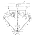
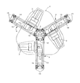
- the substrate transfer apparatus includes a parallel mechanism configured by using a highly rigid gantry 1 straddling a conveyor as a base.
- the substrate W to be transferred is made of a rectangular silicon wafer that constitutes a solar cell, and the vertical and horizontal dimensions thereof are, for example, 125 mm ⁇ 125 mm or 156 mm ⁇ 156 mm, and the thickness dimension is 0.1 to 0.2 mm.
- the parallel mechanism includes a base 2 fixed to the gantry 1, three drive motors 3 disposed on the lower surface of the base 2, and three sets of arm units 4 driven by the respective motors 3.
- the hand unit 5 supported by each arm unit 4 and the like.
- the hand unit 5 is provided with a pivot 7 which is rotationally driven via a pivot drive shaft 6. Further, a joint body 8, a Bernoulli chuck 9, and a plurality of restriction pins 10 are provided on the lower surface side of the hand portion 5.
- the drive motor 3 is assembled to the base 2 via a motor bracket, and the upper end of the arm unit 4 is connected to the output shaft thereof.
- the drive motor 3 integrally includes a servomotor and a reduction gear, and outputs to the arm unit 4 the reciprocating turning power decelerated by the reduction gear.
- the arm unit 4 includes a drive arm 13 and a pair of parallel rods 14 for transmitting the pivoting operation of the drive arm 13 to the hand unit 5.
- the upper end and the lower end of the rod 14 are connected to the drive arm 13 and the hand 5 via a ball joint 15 respectively. Both rods 14 are biased towards each other by a spring 16.
- the pivoting drive shaft 6 is composed of a telescopic ball spline shaft 18 and a universal joint 19 connected to the upper and lower ends thereof.
- the upper universal joint 19 is connected to the output shaft of the motor 20, and the lower universal joint 19 is connected to the pivot shaft 7.
- the motor 20 for driving the turning drive shaft 6 is constituted by a servomotor and a speed reducer as in the case of the above-described drive motor 3.
- the motor 20 is disposed on the upper surface of the base 2.
- the hand portion 5 is formed of a forked plate-like block, and the pivot shaft 7 is rotatably supported at its central portion by a cross roller bearing 21 (see FIG. 4).
- the joint body 8 is fixed to the lower surface of the pivot shaft 7, and the Bernoulli chuck 9 is fixed to the lower surface of the joint body 8.
- the joint body 8 is formed in a shallow bottomed cylindrical shape that opens downward, and fastening seats 23 for fastening the Bernoulli chuck 9 overhang at four places on the lower end circumferential surface of the cylindrical wall. It is formed.
- the entire joint body 8 is formed of a high strength material such as an engineering plastic such as aluminum alloy and polyetheretherketone (PEEK) or a fiber reinforced plastic (FRP). Furthermore, in order to reduce the weight, a large number of reduced-thickness holes 24 are formed in the upper end wall of the joint body 8 so as to penetrate vertically.
- a high strength material such as an engineering plastic such as aluminum alloy and polyetheretherketone (PEEK) or a fiber reinforced plastic (FRP).
- PEEK polyetheretherketone
- FRP fiber reinforced plastic
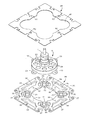
- the Bernoulli Chuck 9 comprises a flat chuck base 26 fixed to the lower surface of the joint body 8 and four chucks fixed to the lower surface of the chuck base 26, as shown in FIGS. A unit 27 and a shield plate 28 fixed to the upper surface of the chuck base 26 are provided.
- the basic shape of the chuck base 26 is formed into a square which is larger than the substrate W by one turn.
- the seats 32 are alternately formed.
- pin fastening seats 33 for fastening the restriction pins 10 are formed in a straight line on each side of the chuck base 26. Adjacent chuck fastening seats 31 are connected via a joint fastening seat 32.
- the chuck base 26 is made of a material that is light in weight and at the same time has a small warpage and deflection and a high bending strength so that the lower surface of the chuck unit 27 facing the substrate W is substantially flush.
- a material of this type for example, a commercially available material (trade name Unilate) obtained by heating and laminating a plate made of polyethylene terephthalate (PET) filled with glass fiber and an inorganic filler may be applied.
- PET polyethylene terephthalate
- a weight reduction space is formed around the above-described chuck fastening seat 31, joint fastening seat 32, and pin fastening seat 33 to achieve weight reduction.
- a generally circular reduced-thickness hole (cavity) 34 surrounded by four chuck fastening seats 31 and a joint fastening seat 32 is provided in a central portion of the chuck base 26.
- four substantially trapezoidal reduced-thickness openings (hollows) 35 are provided between the joint fastening seat 32 and the pin fastening seat 33.
- three wall thinning grooves (wall thinning spaces) 36 are provided around each chuck fastening seat 31, and wall thinning notches (hollows) 37 are provided at four corners of the chuck base 26.
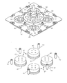
- the chuck unit 27 is configured by a bottomed round cylindrical upper chuck body 40 opening downward, and a bottomed round cylindrical lower chuck body 41 opening upward.
- the lower chuck body 41 is formed of the following materials in consideration of the possibility of contact with the silicon wafer for solar cells.
- the upper chuck body 40 is fastened and fixed to the lower surface of the chuck base 26, and the lower chuck body 41 is fastened and fixed to the lower surface opening side of the upper chuck body 40.
- a substantially cylindrical air chamber 42 is formed between the upper and lower chuck bodies 40 and 41.
- the air chamber 42 is connected to a compressed air supply source (not shown) via an air passage (rubber hose) 43 connected to the circumferential surface of the upper chuck body 40.
- a shallow circular chuck recess 45 opened downward is formed on the lower surface of the lower chuck body 41, and a flat surface 46 is formed continuously on the opening periphery of the chuck recess 45.
- the air chamber 42 and the chuck recess 45 communicate with each other through eight nozzle holes 47.
- the nozzle hole 47 is inclined downward from the air chamber 42 toward the peripheral corner of the chuck recess 45, and the central axis of the nozzle hole 47 is chuck recess 45. It is formed so as to intersect the opening edge of at a predetermined angle.
- the central axis of the air flow blown out from the nozzle hole 47 is directed downward of the opening edge of the chuck recess 45.
- the ratio of the diameter of the chuck recess 45 to the height of the inner peripheral surface of the chuck recess 45 was set to 35: 1.
- the chuck when compressed air is blown out from the nozzle hole 47 in a state of being directed below the opening edge of the chuck recess 45, the chuck is prevented while the air flow is prevented from swirling along the inner peripheral wall of the chuck recess 45 as much as possible.
- the pressure on the central side of the recess 45 can be negative.
- the substrate W to be transferred can be suctioned and held by this negative pressure action.
- the opening surface of the chuck recessed portion 45 including the flat surface 46 is used as the suction surface of the Bernoulli chuck 9
- the substrate W held by suction and the suction surface are vertically moved through a slight gap E as shown in FIG. It is opposite to.
- the air flow blown out from the nozzle hole 47 is discharged to the atmosphere through the gap E.
- the shielding plate 28 is made of a plastic plate having a basic shape the same square as the chuck base 26. At the center of the plate surface of the shielding plate 28, an escape hole 49 is formed along the outer outline of the joint body 8 and the chuck unit 27.
- the shielding plate 28 is disposed to cover the thinning opening 35 and the thinning cutout 37 of the chuck base 26. As described above, when the space above the substrate W is covered with the shielding plate 28, the flow of air when the hand unit 5 moves upward is blocked by the shielding plate 28, and the downward air resistance acts on the substrate W. Therefore, the substrate W can be prevented from falling from the Bernoulli chuck 9.
- a through hole 50 for passing the air passage 43 is formed in a round hole shape.
- the hole 24 of the joint body 8 is opened on the vertical projection plane of the chuck portion, the air flow passes through the previous hole 24 because the hand portion 5 is disposed immediately above and close thereto. It does not hit the substrate W directly.
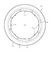
- restriction pins 10 are fixed to each side of the chuck base 26 in a state of projecting downward. Specifically, the restriction pins 10 are disposed at six positions in total at two locations on the left and right of the upper and lower sides and the upper and lower centers of the left and right sides as shown in FIG. 7. Fastening is fixed to the lower surface of the pin fastening seat 33 of 26.
- the three restriction pins 10 on the left half side and the three restriction pins 10 on the right half side are in a line symmetrical positional relationship.
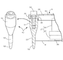
- the restricting pin 10 restricts the sliding movement of the substrate W and the round shaft-shaped shaft portion 51, the downwardly tapered tapered introduction shaft portion 52 formed at the lower end of the shaft portion 51, and A restriction shaft portion 53 is provided, and the whole is formed of a highly durable plastic material to reduce weight.
- the upper peripheral edge of the substrate W suction-held by the Bernoulli chuck 9 is received by the tapered introduction shaft portion 52 so that the introduction shaft portion 52 doubles as the restriction shaft portion 53. Therefore, the upper and lower positions of the restriction pin 10 are set such that the suction surface of the Bernoulli chuck 9 is located on the horizontal surface intersecting the middle portion between the upper and lower sides of the introduction shaft portion 52.
- the taper angle of the introduction shaft 52 is 90 degrees.
- the substrate W is a solar cell silicon wafer
- a plastic material forming the control pin 10 ultra high molecular weight polyethylene (UHPE), PEEK, polyacetal (POM), polytetrafluoroethylene (PTFE), polyimide (PI)
- UHPE ultra high molecular weight polyethylene
- PEEK polyacetal
- PTFE polytetrafluoroethylene
- PI polyimide
- the individual substrates W sent by the first conveyor 60 can be separated from 2 Used when transferring to the tray 62 on the conveyor 61.
- the driving state of the motor M for driving each of the conveyors 60 and 61 is fed back to the control unit 64 via the encoder 63.
- the position signal and the posture information of the substrate W transported by the first conveyor 60 are obtained from the photographed image by the imaging device 65 including the camera unit and the image processing unit, and are output to the control unit 64.
- positional information of the trays 62 transported by the first conveyor 60 is output to the control unit 64 via the optical sensor 66.
- the transfer operation of the substrate W is performed in the following procedure. While displacing the hand unit 5 and Bernoulli chuck 9 just above the substrate W in accordance with the timing at which the substrate W reaches a predetermined pickup position, the swivel shaft 7 is rotationally driven by an angle ⁇ between them to move the Bernoulli chuck 9 The posture of this is adapted to the inclined posture of the substrate W. By lowering the Bernoulli chuck 9 in this state to a predetermined height at which the lower end of the restriction pin 10 does not contact the upper surface of the first conveyor 60 and the substrate W can be adsorbed, the Bernoulli chuck on the conveyor is placed. The suction and hold is performed at 9 and the position is regulated at the same time by the regulating pin 10.
- the pivot shaft 7 is pivoted by an angle ⁇ in the direction opposite to the previous pivoting direction, and the attitude of the Bernoulli chuck 9 is transferred based on the tray 62 Return to the loading position.
- the substrate W is dropped onto the tray 62 by stopping the supply of the compressed air to the air chamber 42 by lowering the hand unit 5 and the Bernoulli chuck 9 to a predetermined transfer position of the tray 62, and the transfer is completed. .
- the substrate W on the first conveyor 60 can be properly transferred onto the tray 62 on the second conveyor 61 by repeatedly performing the above operation.
- the substrates W are orderly transferred onto the tray 62 in the form of a linear array in the vertical and horizontal directions.
- the control unit 64 sequentially takes in the position information from the encoder 63 There is. Therefore, the change position can be calculated in real time to correct the target position. As a result, the substrate W can not be removed or placed on the tray 62.
- the positional accuracy of the hand portion 5 and the Bernoulli chuck 9 with respect to the substrate W is made gentle. Transfer work can be done more quickly.
- the tapered introduction shaft portion 52 is provided at the lower end of the restriction pin 10
- the lower end position of the restriction pin 10 in contact with the upper surface of the conveyor and the peripheral position of the substrate W properly held by suction with the Bernoulli chuck 9
- the parallel mechanism positions the hand portion 5 and Bernoulli chuck 9 relative to the substrate W, it is possible to anticipate variations with the above margin size G as a limit.
- the accuracy can be relaxed.
- the positioning of the hand unit 5 and Bernoulli chuck 9 can be performed more quickly because the positional accuracy with respect to the substrate W is gentle, the transfer efficiency of the substrate W can be operated at a higher speed by taking advantage of the characteristics of the parallel mechanism. Can be improved.
- the substrate W can be transferred with high positional accuracy to the tray 62, and an orderly transfer result can be obtained.
- the contact state between the peripheral edge of the substrate W and the restricting shaft portion 53 is point contact.
- FIG. 10 shows another embodiment of the restricting pin 10.
- a round shaft shaped restricting shaft portion 53 having a diameter smaller than that of the shaft portion 51 is provided on the lower side of the shaft portion 51, and a tapered tapered introduction shaft portion 52 is provided on the lower side of the restricting shaft portion 53.
- the whole of the pin 10 was formed in a bullet shape.
- the lower half of the shaft 51 is formed to be tapered downward.
- the embodiment described above is performed by positioning the substrate W with the round shaft shaped regulation shaft 53. Compared to the example, there is an advantage that the horizontal movement of the substrate W can be reliably suppressed.
- the suction surface of the Bernoulli chuck 9 in this embodiment is located on a horizontal surface intersecting with the lower half circumferential surface of the regulation shaft 53. Further, the margin G corresponds to the horizontal component of the tapered surface of the introduction shaft 52.
- the other parts are the same as in the previous embodiment, so the same reference numerals are given to the same members and the description thereof will be omitted.
- the Bernoulli chuck 9 is configured by the four chuck units 27, but it is not necessary.
- the Bernoulli chuck 9 can be configured with one chuck unit as a suction element of the substrate W. .
- the chuck unit can be directly fixed to the joint body 8, and furthermore, the restriction pin 10 can be fixed using the chuck unit.
- the joint body 8 and the chuck base 26 can be integrally formed.
- the arrangement number and arrangement form of the restriction pins 10 can be changed according to the size and shape of the substrate W. In the above embodiment, the number of arranging the restriction pins 10 is six, but it is not necessary. It is sufficient if at least four restriction pins 10 can receive the four sides of the substrate W. Further, the total number of the restriction pins 10 can be appropriately increased as long as it is four or more.
Landscapes
- Engineering & Computer Science (AREA)
- Robotics (AREA)
- Mechanical Engineering (AREA)
- Physics & Mathematics (AREA)
- Condensed Matter Physics & Semiconductors (AREA)
- General Physics & Mathematics (AREA)
- Manufacturing & Machinery (AREA)
- Computer Hardware Design (AREA)
- Microelectronics & Electronic Packaging (AREA)
- Power Engineering (AREA)
- Container, Conveyance, Adherence, Positioning, Of Wafer (AREA)
Abstract
基板移載装置は、パラレルメカニズムのハンド部(5)に装着され、ベルヌーイチャック(9)と、複数個の規制ピン(10)とを備えている。ベルヌーイチャック(9)は、パラレルメカニズムのハンド部(5)に、基板(W)を非接触状態で保持する吸着面を有する。複数個の規制ピン(10)は、ベルヌーイチャック(9)の周囲を囲む状態で配置される。各規制ピン(10)は、丸軸状であり、下端に設けられた下すぼまりテーパー状の導入軸部(52)と、基板(W)の周縁を受け止めて水平面上の移動を規制する規制軸部(53)とを有している。
Description
本発明は、基板を移載するための装置、特にパラレルメカニズムを移載機構にして、ハンド部に設けたベルヌーイチャックで基板を非接触状態で保持して移載する装置に関する。基板としては、例えば太陽電池用の矩形状のシリコンウェハーを挙げることができる。
この種のベルヌーイチャックを使用して、太陽電池用の基板を移載することは特許文献1に公知である。そこでは、四角形状のハンド部の下面中央にベルヌーイチャックを配置し、ハンド部の対角隅部に吸着パッドを配置している。吸着パッドの近傍には、ブラシ状の摺接体が設けてある。移載時には、吸着パッドで基板の対角隅部を吸着し、同時にベルヌーイチャックで基板の中央部を吸引保持する。摺接体を基板の隅部に接触させた状態でハンド部を上昇させることにより、移載対象の基板の下面に密着していた基板を強制的に分離して、最上面の基板のみを取り出して移載できる。
本発明では、ベルヌーイチャックで吸引保持した基板を、ガイドピンで所定姿勢に位置保持するが、この種のガイドピンを備えた移載装置は特許文献2に開示がある。そこでは、下向きに開口する円筒状の支持体の内面に4個のベルヌーイチャックを配置し、支持体の周面4箇所に丸棒状のガイドピンを設けている。各ベルヌーイチャックで同時に吸引保持された円形の基板は、その周面がガイドピンで受け止められており、したがって、移載運動時に基板が吸着面に沿って移動するのをガイドピンで規制できる。
特許文献3には、ガイド体の下部に設けた傾斜面で基板の周縁を受け止めて、ベルヌーイチャックで吸着した基板が水平方向へ移動するのを規制する移載装置が開示されている。傾斜面は、ベルヌーイチャックの吸着平面と交差する状態で設けられている。
特許文献4には、円盤状の保持ベースの下面に3個のベルヌーイチャックを配置し、保持ベースの下面周縁の6個所に配置した規制ブロックで、半導体ウェーハーの周縁を受け止めるようにした移載装置が開示してある。保持ベースは、ベルヌーイチャックに吸引保持された半導体ウェーハーの上方空間を覆っている。
ベルヌーイチャックに関して、本出願人は特許文献5を出願しており、そこでは、円盤状のチャック本体の下面に浅い凹部を設け、凹部の周囲4箇所に加圧空気を斜めに吹き出すノズルを配置している。凹部の開口縁の周りにはフランジ状の平坦面を形成している。
本発明では、移載装置の主要部をパラレルメカニズムで構成するが、パラレルメカニズムの基本構造は、本出願人の出願に係る特許文献6に公知である。そこでは、ベースに配置される3個の駆動モーターと、各駆動モーターで駆動操作される3組のアームユニットと、アームユニットで支持されるハンド部と、ハンド部に設けた旋回軸に回転動力を伝動する旋回駆動軸などでパラレルメカニズムを構成している。
特許文献1の移載装置では、ベルヌーイチャックと吸着パッドとで基板を吸着保持するので、移載運動時に基板がベルヌーイチャックの吸着面に沿ってずれ動くのを、吸着パッドで確実に防止できる。しかし、吸着パッドで基板を吸着固定するので、他物との接触を嫌う基板の移載に適さない。
その点、特許文献2の移載装置によれば、ベルヌーイチャックで吸引保持した基板の周縁を、複数個のガイドピンの周面で受け止めて、移載運動時に基板が吸着面に沿って移動するのを規制することができるので、非接触状態での移載が可能となる。しかし、ガイドピンが丸棒状に形成されているため、基板を吸引保持するときの、支持体の基板に対する位置精度を高精度化する必要があり、基板の移載を能率よく行なうことができない。因みに、基板を吸引保持するときの支持体の位置精度が充分でないと、ガイドピンの周面を通る仮想円の内部に基板を位置させることができず、基板をベルヌーイチャックで適正に吸引保持できなくなる。
特許文献3の移載装置においては、ガイド体の下部に設けた傾斜面で基板の周縁を受け止めるので、ベルヌーイチャックで基板を吸引保持するときの支持体の位置精度を、緩やかなものとすることができる。しかし、先の傾斜面を2次元平面からなる勾配面で形成するので、ベルヌーイチャックで吸引保持した基板の中心と、ベルヌーイチャックの中心とがずれるおそれがあり、したがって、移載先における基板の位置精度にばらつきを生じやすい。
本発明の目的は、ベルヌーイチャックで基板を吸引保持するときのハンド部の位置精度を緩やかなものとして、非接触状態での基板の移載を高速度で能率よく行なえる基板移載装置を提供することにある。
以下に、課題を解決するための手段として複数の態様を説明する。これら態様は、必要に応じて任意に組み合せることができる。
本発明の一見地に係る基板移載装置は、パラレルメカニズムのハンド部に装着され、ベルヌーイチャックと、複数個の規制ピンとを備えている。ベルヌーイチャックは、パラレルメカニズムのハンド部に、基板を非接触状態で保持する吸着面を有する。複数個の規制ピンは、ベルヌーイチャックの周囲を囲む状態で配置される。各規制ピンは、丸軸状であり、下端に設けられた下すぼまりテーパー状の導入軸部と、基板の周縁を受け止めて水平面上の移動を規制する規制軸部とを有している。
上記のように、規制ピンの下端にテーパー状の導入軸部を設けると、ベルヌーイチャックを基板に対して位置決めするときの位置座標に関して、傾斜する導入軸部の水平成分に相当する余裕寸法を見込むことができる。つまり、位置決めした状態の規制ピンと吸引前の基板とが僅かにずれていたとしても、ずれ寸法が先の余裕寸法の範囲内にある限り、規制ピンが基板に当接することはなく、その分だけ規制ピンの取付精度、および寸法精度を含む位置精度を緩やかにできる。また、基板に対する要求位置決め精度が緩やかな分だけ、ベルヌーイチャックの位置決めをより迅速に行なえる。したがって、本発明の一見地に係る移載装置によれば、ベルヌーイチャックで基板を保持するときに、ハンド部に要求される位置決め精度を緩やかなものとして、非接触状態での基板の移載を高速度で能率よく行なうことができる。
さらに、基板をベルヌーイチャックで保持する過程で、基板の周縁を導入軸部で案内して、基板とベルヌーイチャックずれを矯正するので、基板を高い位置精度で移載先へ移載することができる。
ベルヌーイチャックの吸着面が、導入軸部の中心軸と直交する平面上に位置されており、導入軸部と規制軸部が一つの部分として形成されいてもよい。
この場合、規制軸部を導入軸部で兼ねられているので、ベルヌーイチャックで保持した状態の基板の周縁をテーパー面状の導入軸部で受け止めて、基板を常に適正な姿勢に矯正した状態で吸引保持することができる。そのため、非接触状態で吸引保持された基板を移送するとき、周縁に作用する空気抵抗の違いで基板が揺れ動くのを防止できる。また、基板を各規制ピンで適正な姿勢に保持した状態で移載するので、基板を高い位置精度で移載先へ移載することができる。加えて、空気抵抗を受けた基板が、ベルヌーイチャックの吸着面側へ押し付けられるような場合に、基板の周縁をテーパー面状の導入軸部で受け止めて、基板が限界位置を越えて移動するのを規制し、ベルヌーイチャックに接触して傷つくのを防止できる。
この場合、規制軸部を導入軸部で兼ねられているので、ベルヌーイチャックで保持した状態の基板の周縁をテーパー面状の導入軸部で受け止めて、基板を常に適正な姿勢に矯正した状態で吸引保持することができる。そのため、非接触状態で吸引保持された基板を移送するとき、周縁に作用する空気抵抗の違いで基板が揺れ動くのを防止できる。また、基板を各規制ピンで適正な姿勢に保持した状態で移載するので、基板を高い位置精度で移載先へ移載することができる。加えて、空気抵抗を受けた基板が、ベルヌーイチャックの吸着面側へ押し付けられるような場合に、基板の周縁をテーパー面状の導入軸部で受け止めて、基板が限界位置を越えて移動するのを規制し、ベルヌーイチャックに接触して傷つくのを防止できる。
ベルヌーイチャックは、ハンド部の下面側に固定される平板状のチャックベースと、チャックベースの下面に固定される複数個のチャックユニットとを有してもよい。その場合、規制ピンは、チャックベースの周縁複数個所に固定される。
チャックベースと、その下面に固定される複数個のチャックユニットとでベルヌーイチャックを構成しているので、移載対象となる基板の形状や大きさ等に応じて、チャックユニットの配置個数や配置形態を変更することができる。したがって、無駄のないベルヌーイチャックを構成できる。また、複数のチャックユニットで基板を同時に保持するので、単一のチャックユニットで基板を保持する場合に比べて、より安定した状態で基板を保持できる。チャックベースを利用して、その周縁複数個所に規制ピンを固定するので、規制ピンとチャックユニットとの組み付け精度を高度化できる。
チャックベースと、その下面に固定される複数個のチャックユニットとでベルヌーイチャックを構成しているので、移載対象となる基板の形状や大きさ等に応じて、チャックユニットの配置個数や配置形態を変更することができる。したがって、無駄のないベルヌーイチャックを構成できる。また、複数のチャックユニットで基板を同時に保持するので、単一のチャックユニットで基板を保持する場合に比べて、より安定した状態で基板を保持できる。チャックベースを利用して、その周縁複数個所に規制ピンを固定するので、規制ピンとチャックユニットとの組み付け精度を高度化できる。
ハンド部の中央に軸支した旋回軸の下面に固定されたジョイント体をさらに備えてもよい。その場合、チャックベースが、ジョイント体の下面に固定される。ジョイント体と、チャックベースと、チャックユニットと、規制ピンのそれぞれが、プラスチック材で形成されている。
この場合、ジョイント体、チャックベース、チャックユニットと、規制ピンのそれぞれをプラスチック材で形成しているので、金属材で先の各部材を形成する場合に比べて、ハンド部に組み付けられるベルヌーイチャックを軽量化できる。ハンド部に作用する全重量を軽減できる分だけ、パラレルメカニズムが作動するときのハンド部の運動慣性力を小さくして、移載作業を高速化でき、基板の移載を能率よく行なえる。また、先の各部材が万一基板と接触した場合でも、硬度の低いプラスチック材であれば、基板に与えるダメージを軽減できる。
この場合、ジョイント体、チャックベース、チャックユニットと、規制ピンのそれぞれをプラスチック材で形成しているので、金属材で先の各部材を形成する場合に比べて、ハンド部に組み付けられるベルヌーイチャックを軽量化できる。ハンド部に作用する全重量を軽減できる分だけ、パラレルメカニズムが作動するときのハンド部の運動慣性力を小さくして、移載作業を高速化でき、基板の移載を能率よく行なえる。また、先の各部材が万一基板と接触した場合でも、硬度の低いプラスチック材であれば、基板に与えるダメージを軽減できる。
チャックベースは、チャックユニットが締結されるチャック締結座と、規制ピンを締結するためのピン締結座と、ジョイント体を締結するためのジョイント締結座を備えてもよい。その場合、チャックベースには、チャック締結座、ピン締結座、およびジョイント締結座の周囲に、複数の空洞部が形成されている。
この場合、チャックベースが、チャック締結座と、ピン締結座と、ジョイント締結座とを備えているので、各締結座の周囲に複数の空洞部を形成すると、チャックベースの重量を削減して、ベルヌーイチャックをさらに軽量化できる。したがって、パラレルメカニズムが作動するときの運動慣性力をさらに小さくして移載作業を高速化できる。
この場合、チャックベースが、チャック締結座と、ピン締結座と、ジョイント締結座とを備えているので、各締結座の周囲に複数の空洞部を形成すると、チャックベースの重量を削減して、ベルヌーイチャックをさらに軽量化できる。したがって、パラレルメカニズムが作動するときの運動慣性力をさらに小さくして移載作業を高速化できる。
ベルヌーイチャックは、チャックベースの上面に固定された、ベルヌーイチャックで保持された基板の上面の少なくとも一部を覆う遮蔽板をさらに有してもよい。その場合、遮蔽板には、チャックベースの複数の空洞部に連通する複数の空気通路が形成されている。
この場合、チャックベースの上面に遮蔽板を固定して、ベルヌーイチャックで保持された基板の上面の少なくとも一部を遮蔽板で覆っているので、ハンド部が上方へ移動するときの空気の流れを遮蔽板で遮って、基板に下向きの空気抵抗が作用するのを解消できる。したがって、基板に作用する空気抵抗によって、基板の保持状態が不安定になって揺れ動き、あるいはベルヌーイチャックから落下するのを防止でき、基板を安定した状態のもとに高速度で移載できる。
この場合、チャックベースの上面に遮蔽板を固定して、ベルヌーイチャックで保持された基板の上面の少なくとも一部を遮蔽板で覆っているので、ハンド部が上方へ移動するときの空気の流れを遮蔽板で遮って、基板に下向きの空気抵抗が作用するのを解消できる。したがって、基板に作用する空気抵抗によって、基板の保持状態が不安定になって揺れ動き、あるいはベルヌーイチャックから落下するのを防止でき、基板を安定した状態のもとに高速度で移載できる。
各チャックユニットは、チャックベースの下面に固定される上チャック体と、上チャック体の下面に固定される下チャック体とで構成されてもよい。その場合、上チャック体と下チャック体の間に空気チャンバーが形成されている。下チャック体には、下向きに開口するチャック凹部と、チャック凹部の周囲にある平坦面と、チャック凹部の周縁に沿って設けられ空気チャンバーとチャック凹部とを連通する複数個のノズル穴とが形成されている。ノズル穴は、吹き出される空気流が、チャック凹部の周縁の下方へ向かって延びるように、向けられている。
この場合、周縁の下方を指向する状態で空気流をチャック凹部内に吹き出すので、空気流がチャック凹部内で旋回するのを避けながら、チャック凹部の中央部側に負圧を発生することができる。したがって、空気流が旋回することに伴なう動圧の損失を抑止でき、これに伴ない供給空気量あたりの吸着力を増加して基板を効果的に吸引保持できる。
この場合、周縁の下方を指向する状態で空気流をチャック凹部内に吹き出すので、空気流がチャック凹部内で旋回するのを避けながら、チャック凹部の中央部側に負圧を発生することができる。したがって、空気流が旋回することに伴なう動圧の損失を抑止でき、これに伴ない供給空気量あたりの吸着力を増加して基板を効果的に吸引保持できる。
規制ピンは、超高分子量ポリエチレン等のプラスチック材を樹脂成形し、さらに機械加工を施して形成されてもよい。
規制ピンが超高分子量ポリエチレン等の極めて高い平均分子量を持つプラスチック材で形成しているので、軽量化を実現しながら、耐衝撃性や、耐摩耗性などに優れた材料特性を発揮でき、長期使用時にも金属部品に匹敵する耐久性を発揮できる。一方で、この種のプラスチック材は溶融時の流動性が低く成形困難であるが、例えば、この種のプラスチック材で形成した市販の棒材を素材にして旋削加工によって形成すると、寸法精度に優れた規制ピンをより低コストで得ることができる。
規制ピンが超高分子量ポリエチレン等の極めて高い平均分子量を持つプラスチック材で形成しているので、軽量化を実現しながら、耐衝撃性や、耐摩耗性などに優れた材料特性を発揮でき、長期使用時にも金属部品に匹敵する耐久性を発揮できる。一方で、この種のプラスチック材は溶融時の流動性が低く成形困難であるが、例えば、この種のプラスチック材で形成した市販の棒材を素材にして旋削加工によって形成すると、寸法精度に優れた規制ピンをより低コストで得ることができる。
(1)移載装置
図1~図9は本発明に係る基板移載装置の一実施例を示す。図2において基板移載装置は、コンベアを跨ぐ高剛性の架台1を基体にして構成したパラレルメカニズムを備える。移載対象の基板Wは、太陽電池を構成する矩形のシリコンウェハーからなり、その縦横寸法は例えば125mm×125mm、あるいは156mm×156mm、厚み寸法は0.1~0.2mmである。図2に示すように、パラレルメカニズムは、架台1に固定されるベース2と、ベース2の下面に配置される3個の駆動モーター3と、各モーター3で駆動される3組のアームユニット4と、各アームユニット4で支持されるハンド部5などで構成する。ハンド部5には旋回駆動軸6を介して旋回駆動される旋回軸7が設けられている。また、ハンド部5の下面側にはジョイント体8と、ベルヌーイチャック9と、複数個の規制ピン10とが設けてられている。
図1~図9は本発明に係る基板移載装置の一実施例を示す。図2において基板移載装置は、コンベアを跨ぐ高剛性の架台1を基体にして構成したパラレルメカニズムを備える。移載対象の基板Wは、太陽電池を構成する矩形のシリコンウェハーからなり、その縦横寸法は例えば125mm×125mm、あるいは156mm×156mm、厚み寸法は0.1~0.2mmである。図2に示すように、パラレルメカニズムは、架台1に固定されるベース2と、ベース2の下面に配置される3個の駆動モーター3と、各モーター3で駆動される3組のアームユニット4と、各アームユニット4で支持されるハンド部5などで構成する。ハンド部5には旋回駆動軸6を介して旋回駆動される旋回軸7が設けられている。また、ハンド部5の下面側にはジョイント体8と、ベルヌーイチャック9と、複数個の規制ピン10とが設けてられている。
駆動モーター3はモーターブラケットを介してベース2に組み付けられており、その出力軸にアームユニット4の上端が連結されている。駆動モーター3は、サーボモーターと減速機とを一体に備え、減速機で減速された往復旋回動力をアームユニット4に出力する。
アームユニット4は、駆動アーム13と、駆動アーム13の旋回動作をハンド部5に伝える一対の平行なロッド14とで構成する。ロッド14の上端および下端は、それぞれボール継手15を介して駆動アーム13およびハンド部5に連結されている。両ロッド14はばね16で互いに接近する向きに付勢されている。各アームユニット4を駆動モーター3で駆動することにより、ハンド部5を所定の3次元空間内で自由に変位操作することができる。
ハンド部5の3次元変位に追随しながら旋回動力を伝動するために、伸縮自在なボールスプライン軸18と、その上下端に連結したユニバーサルジョイント19とで旋回駆動軸6を構成する。上側のユニバーサルジョイント19はモーター20の出力軸に、下側のユニバーサルジョイント19は旋回軸7にそれぞれ連結されている。旋回駆動軸6を駆動するモーター20は、先の駆動モーター3と同様にサーボモーターと減速機とで構成されている。また、モーター20はベース2の上面に配置してある。
図3に示すようにハンド部5は、三又状の板状ブロックからなり、その中央部に先の旋回軸7がクロスローラーベアリング21で回転自在に軸支されている(図4参照)。旋回軸7の下面にジョイント体8が固定され、さらにジョイント体8の下面にベルヌーイチャック9が固定されている。図5に示すように、ジョイント体8は下向きに開口する浅い有底筒状に形成されており、その筒壁の下端周面の4個所にベルヌーイチャック9を締結するための締結座23が張り出し形成されている。軽量化のために、ジョイント体8の全体を、例えばアルミニウム合金やポリエーテルエーテルケトン(PEEK)等のエンジニアリングプラスチック、あるいは繊維強化プラスチック(FRP)等の高強度の材料で形成している。さらに、軽量化のために、ジョイント体8の上端壁に多数個の減肉穴24を上下貫通状に形成した。
(2)ベルヌーイチャック
ベルヌーイチャック9は、図5及び図6に示すように、ジョイント体8の下面に固定される平板状のチャックベース26と、チャックベース26の下面に固定される4個のチャックユニット27と、チャックベース26の上面に固定される遮蔽板28などで構成されている。チャックベース26の基本形状は、基板Wよりひとまわり回り大きな正方形に形成されている。図5に示すように、チャックベース26の板面の4個所には、チャックユニット27を締結するためのリング状のチャック締結座31と、ジョイント体8を締結するための部分円弧状のジョイント締結座32が交互に形成されている。また、チャックベース26の各辺部には、規制ピン10を締結するためのピン締結座33が直線状に形成されている。隣接するチャック締結座31は、ジョイント締結座32を介して繋がっている。
ベルヌーイチャック9は、図5及び図6に示すように、ジョイント体8の下面に固定される平板状のチャックベース26と、チャックベース26の下面に固定される4個のチャックユニット27と、チャックベース26の上面に固定される遮蔽板28などで構成されている。チャックベース26の基本形状は、基板Wよりひとまわり回り大きな正方形に形成されている。図5に示すように、チャックベース26の板面の4個所には、チャックユニット27を締結するためのリング状のチャック締結座31と、ジョイント体8を締結するための部分円弧状のジョイント締結座32が交互に形成されている。また、チャックベース26の各辺部には、規制ピン10を締結するためのピン締結座33が直線状に形成されている。隣接するチャック締結座31は、ジョイント締結座32を介して繋がっている。
チャックベース26は、軽量であると同時に、基板Wに対向するチャックユニット27の下面が略同一平面になるように、反りやたわみが小さく、曲げ強度が高い材料で形成する。この種の材料としては、例えばポリエチレンテレフタレート(PET)にガラス繊維や無機フィラーを充填複合した板材を加熱積層した市販素材(商品名ユニレート)を適用できる。また、先のチャック締結座31、ジョイント締結座32、およびピン締結座33の周囲に減肉空間を形成して、軽量化を図っている。詳しくは、チャックベース26の中央部分に、4個のチャック締結座31と、ジョイント締結座32とで囲まれる概ね円形の減肉穴(空洞)34を設けている。また、ジョイント締結座32とピン締結座33との間に4個の略台形状の減肉開口(空洞)35を設けている。さらに、各チャック締結座31の周囲に3個の減肉溝(減肉空間)36を設け、チャックベース26の四隅部分に減肉切欠(空洞)37を設けている。このように、各締結座31・32・33以外の部分を除去することにより、チャックベース26の重量を削減して運動慣性力を小さくすることができる。
図1においてチャックユニット27は、下向きに開口する有底丸筒状の上チャック体40と、上向きに開口する有底丸筒状の下チャック体41とで構成する。上チャック体40、および下チャック体41のうち、少なくとも下チャック体41は、太陽電池用シリコンウェーハーと接触する可能性を考慮して、以下の材料で形成する。超高分子量ポリエチレン(UHPE)、PEEK,ポリアセタール(POM)、ポリテトラフルオロエチレン(PTFE)、ポリイミド(PI)、ABSのひとつ、あるいはこれらのいくつかを組み合わせたポリマーアロイである。上チャック体40は、チャックベース26の下面に締結固定され、下チャック体41は、上チャック体40の下面開口側に締結固定されている。これにより、上下のチャック体40・41の間に略円柱状の空気チャンバー42が形成される。図4に示すように、空気チャンバー42は、上チャック体40の周面に連結した空気通路(ゴムホース)43を介して、図示していない圧縮空気供給源に接続されている。
下チャック体41の下面には、下向きに開口する浅い円形のチャック凹部45が形成され、チャック凹部45の開口周縁に連続して平坦面46が形成されている。空気チャンバー42とチャック凹部45とは、8個のノズル穴47を介して連通されている。図1および図8に示すように、ノズル穴47は、空気チャンバー42の側からチャック凹部45の周縁隅部の側へ向かって下り傾斜する状態で、しかもノズル穴47の中心軸線がチャック凹部45の開口縁と所定の角度で交差するように形成されている。これにより、ノズル穴47から吹き出される空気流の中心軸は、チャック凹部45の開口縁の下方へ向かって指向する。チャック凹部45の直径寸法と、チャック凹部45の内周面の高さとの比は35対1に設定した。
上記のように、チャック凹部45の開口縁の下方を指向する状態で、圧縮空気をノズル穴47から吹き出すと、空気流がチャック凹部45の内周壁に沿って旋回するのを極力防ぎながら、チャック凹部45の中央部側の圧力を負圧にすることができる。この負圧作用によって移載対象の基板Wを吸引保持できる。なお、平坦面46を含むチャック凹部45の開口面をベルヌーイチャック9の吸着面とするとき、吸引保持された基板Wと吸着面とは、図1に示すように僅かな隙間Eを介して上下に対向している。ノズル穴47から吹き出された空気流は、先の隙間Eを介して大気中に排出される。
上記のように、基板Wをベルヌーイチャック9で吸引保持して搬送する際には、基板Wの表面に空気抵抗が作用して、ベルヌーイチャックによる基板Wの吸引保持状態が不安定になるおそれがある。とくに、運動速度が速いパラレルメカニズムの場合には、大きな空気抵抗が基板Wの表面に作用し、基板Wがベルヌーイチャック9から落下するおそれがある。このような、空気抵抗による基板Wの揺れ動きや落下を防ぐために、チャックベース26の上面に、基板Wの上面全体を覆う遮蔽板28を締結固定している。
図5及び図6に示すように遮蔽板28は、チャックベース26と同じ正方形を基本形状とするプラスチック板材からなる。遮蔽板28の板面の中央には、ジョイント体8とチャックユニット27の外郭線に沿う逃げ穴49が形成してある。遮蔽板28は、チャックベース26の減肉開口35及び減肉切欠37を覆うように配置される。このように、遮蔽板28で基板Wの上方空間を覆うと、ハンド部5が上方へ移動するときの空気の流れを遮蔽板28で遮って、基板Wに下向きの空気抵抗が作用するのを解消でき、したがって基板Wがベルヌーイチャック9から落下するのを防止することができる。逃げ穴49の周囲壁のうち、チャックベース26の減肉開口35に臨む4個所には、空気通路43を通すための通口50が丸穴状に形成してある。なお、チャック部の垂直投影面においては、ジョイント体8の穴24が開口しているが、その真上に近接してハンド部5が配置してあるので、気流が先の穴24を通過して基板Wに直撃することはない。
(3)規制ピン
ベルヌーイチャック9で吸引保持した状態の基板Wは、ベルヌーイチャック9の吸着面に沿って滑り移動しやすく、ハンド部5が水平方向へ移動するとき、ベルヌーイチャック9と相対移動するおそれがある。このような基板Wの滑り移動を規制して基板Wを確実に移載するために、チャックベース26の各辺部に6個の規制ピン10を、下向きに突出する状態で固定している。詳しくは、図7に向かって上下の辺部の左右2個所と、左右の辺部の上下中央部との、合計6個所に規制ピン10を配置し、これらのピン10をボルト54でチャックベース26のピン締結座33の下面に締結固定している。左半側の3個の規制ピン10と、右半側の3個の規制ピン10とは、線対称の位置関係にある。
ベルヌーイチャック9で吸引保持した状態の基板Wは、ベルヌーイチャック9の吸着面に沿って滑り移動しやすく、ハンド部5が水平方向へ移動するとき、ベルヌーイチャック9と相対移動するおそれがある。このような基板Wの滑り移動を規制して基板Wを確実に移載するために、チャックベース26の各辺部に6個の規制ピン10を、下向きに突出する状態で固定している。詳しくは、図7に向かって上下の辺部の左右2個所と、左右の辺部の上下中央部との、合計6個所に規制ピン10を配置し、これらのピン10をボルト54でチャックベース26のピン締結座33の下面に締結固定している。左半側の3個の規制ピン10と、右半側の3個の規制ピン10とは、線対称の位置関係にある。
図1に示すように、規制ピン10は、丸軸状の軸部51と、軸部51の下端に形成される下すぼまりテーパー状の導入軸部52と、基板Wの滑り移動を規制する規制軸部53とを備えており、全体を耐久性に優れたプラスチック材で形成して軽量化している。この実施例では、ベルヌーイチャック9で吸引保持された基板Wの上面周縁を、テーパー状の導入軸部52で受け止めるようにして、導入軸部52が規制軸部53を兼ねるようにした。そのために、ベルヌーイチャック9の吸着面が、導入軸部52の上下中途部と交差する水平面上に位置するように、規制ピン10の上下位置を設定した。導入軸部52のテーパー角度は90度とした。
基板Wが太陽電池シリコンウェーハーである場合の、規制ピン10を形成するプラスチック材としては、超高分子量ポリエチレン(UHPE)、PEEK,ポリアセタール(POM)、ポリテトラフルオロエチレン(PTFE)、ポリイミド(PI)、ABSなどのプラスチック材を用いることが好ましい。しかし、超高分子量ポリエチレンやポリイミドは射出成形が困難であるので、棒状の素材に旋削加工を施して形成すると、寸法精度に優れた規制ピン10を低コストで簡単に形成できる。
(4)移載装置の使用例
上記のように構成した移載装置は、例えば図9に示すように、第1コンベア60で送られてくる個々の基板Wを、同コンベア60に隣接する第2コンベア61上のトレー62に移載する際に使用する。そこでは、各コンベア60・61を駆動するモーターMの駆動状態は、エンコーダー63を介して制御部64へフィードバックされる。また、第1コンベア60で搬送される基板Wの位置信号と姿勢情報とが、カメラ部と画像処理部とからなる撮像装置65によって撮影画像から求められ、制御部64へ出力される。さらに、第1コンベア60で搬送されるトレー62の位置情報が光学センサー66を介して制御部64へ出力される。
上記のように構成した移載装置は、例えば図9に示すように、第1コンベア60で送られてくる個々の基板Wを、同コンベア60に隣接する第2コンベア61上のトレー62に移載する際に使用する。そこでは、各コンベア60・61を駆動するモーターMの駆動状態は、エンコーダー63を介して制御部64へフィードバックされる。また、第1コンベア60で搬送される基板Wの位置信号と姿勢情報とが、カメラ部と画像処理部とからなる撮像装置65によって撮影画像から求められ、制御部64へ出力される。さらに、第1コンベア60で搬送されるトレー62の位置情報が光学センサー66を介して制御部64へ出力される。
基板Wの移載動作は以下の手順で行なう。基板Wが所定のピックアップ位置まで達するタイミングに合わせて、ハンド部5およびベルヌーイチャック9を基板Wの真上へと変位操作しながら、その間に旋回軸7を角度θだけ旋回駆動してベルヌーイチャック9の姿勢を基板Wの傾斜姿勢に適合させる。この状態のベルヌーイチャック9を、規制ピン10の下端が第1コンベア60の上面に接触せず、しかも基板Wを吸着可能な所定高さまで下降させることにより、コンベア上にあった基板Wをベルヌーイチャック9で吸引保持し、同時に規制ピン10で位置規制する。
吸引保持した基板Wをトレー62側へ移送する間に、旋回軸7を先の旋回方向とは逆向きに角度θだけ旋回駆動して、ベルヌーイチャック9の姿勢を、トレー62を基準とする移載姿勢に戻す。ハンド部5およびベルヌーイチャック9をトレー62の所定の移載位置へ下降させ、空気チャンバー42への圧縮空気の供給を停止することにより、基板Wをトレー62上に落下させて移載を完了する。以後、上記の動作を繰り返し行なうことにより、第1コンベア60上の基板Wを、第2コンベア61上のトレー62に適正に移載できる。基板Wは、トレー62に対して、縦横に直線列を構成する状態で整然と移載される。なお、ハンド部5が移動している間に、第1コンベア60および第2コンベア61がモーターMで駆動され、目標位置が変わった場合でも、制御部64はエンコーダー63から位置情報を逐次取り込んでいる。したがって、変更位置をリアルタイムで計算して目標位置を修正することができる。その結果、基板Wを取り損ねたり、トレー62に置き損ねることはない。
(5)効果
コンベア上の基板Wをベルヌーイチャック9で吸引保持する際には、ハンド部5およびベルヌーイチャック9の基板Wに対する位置精度が問題になる。位置精度が不十分であると、規制ピン10が基板Wの上面に当接して基板Wを傷つけるのはもちろん、基板Wを吸引保持することが不可能となる。半面、位置精度が高いほど基板Wを的確に吸引できるものの、位置精度の確保のために、ハンド部5の移動速度を落としたり、慣性力に起因する機構の振動が収まるまで停止したりすると、ハンド部5およびベルヌーイチャック9の位置決めに時間が掛かる。つまり、移載作業を効率よく行なえなくなる。本発明の実施例では、規制ピン10の下端に下すぼまりテーパー状の導入軸部52を設けることで、ハンド部5およびベルヌーイチャック9の基板Wに対する位置精度を緩やかなものとして、基板Wの移載作業をより迅速に行なえるようにした。
コンベア上の基板Wをベルヌーイチャック9で吸引保持する際には、ハンド部5およびベルヌーイチャック9の基板Wに対する位置精度が問題になる。位置精度が不十分であると、規制ピン10が基板Wの上面に当接して基板Wを傷つけるのはもちろん、基板Wを吸引保持することが不可能となる。半面、位置精度が高いほど基板Wを的確に吸引できるものの、位置精度の確保のために、ハンド部5の移動速度を落としたり、慣性力に起因する機構の振動が収まるまで停止したりすると、ハンド部5およびベルヌーイチャック9の位置決めに時間が掛かる。つまり、移載作業を効率よく行なえなくなる。本発明の実施例では、規制ピン10の下端に下すぼまりテーパー状の導入軸部52を設けることで、ハンド部5およびベルヌーイチャック9の基板Wに対する位置精度を緩やかなものとして、基板Wの移載作業をより迅速に行なえるようにした。
詳しくは、規制ピン10の下端にテーパー状の導入軸部52を設けると、コンベアの上面に当接する規制ピン10の下端位置と、ベルヌーイチャック9で適正に吸引保持された基板Wの周縁位置とに、図1に符号Gで示す余裕寸法を持つことができる。そのため、位置決めした状態の規制ピン10と、吸引前の基板Wとの間に僅かなずれがあったとしても、ずれ寸法が先の余裕寸法Gの範囲内にある限り、規制ピン10の下端が基板Wに当接することはない。したがって、パラレルメカニズムがハンド部5およびベルヌーイチャック9を基板Wに対して位置決めするときの目標値(XY座標)に関して、先の余裕寸法Gを限界とするばらつきを見込むことができ、その分だけ位置精度を緩やかにできる。また、基板Wに対する位置精度が緩やかな分だけ、ハンド部5およびベルヌーイチャック9の位置決めをより迅速に行なえるので、パラレルメカニズムの特性を生かしてより高速度で作動させ、基板Wの移載能率を向上できる。
規制ピン10と基板Wとに僅かなずれがある状態において、ベルヌーイチャック9で基板Wを吸着すると、ベルヌーイチャック9の中心に対して偏寄している側の基板Wの周縁が、他に先行して導入軸部52に当接する。さらに、基板Wがベルヌーイチャック9の吸着面へ接近するのに伴なって、基板Wの周縁をテーパー状の導入軸部52で先の偏寄方向とは逆向きに案内して、基板Wとベルヌーイチャック9とのずれを修復することができる。そのため、基板Wを常に偏りのない姿勢に矯正した状態で吸引保持できる。さらに、移送時に周縁に作用する空気抵抗の違いで基板Wが揺れ動くのを解消できる。また、各規制ピン10で自動的に調心した状態の基板Wを移載するので、基板Wをトレー62に対して高い位置精度で移載でき、整然とした移載結果が得られる。因みに、基板Wの周縁と規制軸部53との接触状態は点接触となる。
(6)他の実施形態
以上、本発明の一実施形態について説明したが、本発明は上記実施形態に限定されるものではなく、発明の要旨を逸脱しない範囲で種々の変更が可能である。特に、本明細書に書かれた複数の実施形態および変形例は必要に応じて任意に組合せ可能である。
以上、本発明の一実施形態について説明したが、本発明は上記実施形態に限定されるものではなく、発明の要旨を逸脱しない範囲で種々の変更が可能である。特に、本明細書に書かれた複数の実施形態および変形例は必要に応じて任意に組合せ可能である。
(A)図10は規制ピン10の別の実施例を示す。そこでは軸部51の下側に、軸部51より小径の丸軸状の規制軸部53を設け、規制軸部53の下側に下すぼまりテーパー状の導入軸部52を設けて、規制ピン10の全体を銃弾状に形成した。軽量化のために、軸部51の下半部は下すぼまりテーパー状に形成した。このように規制軸部53で基板Wを位置決めすると、基板Wがたわんだり振動したりする場合に、基板外周部が規制軸部53に擦れる可能性がある。しかし、基板Wがたわんだり振動する現象が殆どないか、基板Wが擦れることが問題にならない場合には、丸軸状の規制軸部53で基板Wを位置決めすることにより、先に説明した実施例に比べて基板Wの水平方向の移動を確実に抑えられる利点がある。この実施例におけるベルヌーイチャック9の吸着面は、規制軸部53の下半部周面と交差する水平面上に位置させてある。また、余裕寸法Gは、導入軸部52のテーパー面の水平成分に相当する。他は先の実施例と同じであるので、同じ部材に同じ符号を付してその説明を省略する。
(B)上記の実施例では、4個のチャックユニット27でベルヌーイチャック9を構成したが、その必要はなく、1個のチャックユニットを基板Wの吸着要素としてベルヌーイチャック9を構成することができる。その場合には、チャックユニットをジョイント体8に直接固定することができ、さらに、チャックユニットを利用して規制ピン10を固定することができる。ジョイント体8とチャックベース26は一体に形成することができる。規制ピン10の配置個数および配置形態は、基板Wの大きさや形状に応じて変更することができる。また、上記の実施例では規制ピン10の配置個数を6個としたが、その必要はなく、少なくとも4個の規制ピン10で基板Wの四辺部分を受止めることができれば足りる。また、規制ピン10の総数は4個以上であれば適宜増やすことができる。
5 パラレルメカニズムのハンド部
7 旋回軸
9 ベルヌーイチャック
10 規制ピン
26 チャックベース
27 チャックユニット
28 遮蔽板
45 チャック凹部
46 平坦面
52 導入軸部
53 規制軸部
7 旋回軸
9 ベルヌーイチャック
10 規制ピン
26 チャックベース
27 チャックユニット
28 遮蔽板
45 チャック凹部
46 平坦面
52 導入軸部
53 規制軸部
Claims (8)
- パラレルメカニズムのハンド部に装着される基板移載装置であって、
基板を非接触状態で保持する吸着面を有するベルヌーイチャックと、
前記ベルヌーイチャックの周囲を囲む状態で配置される複数個の規制ピンとを備えており、
前記各規制ピンは、丸軸状であり、下端に設けられた下すぼまりテーパー状の導入軸部と、前記基板の周縁を受け止めて水平面上の移動を規制する規制軸部とを有している、基板移載装置。 - 前記ベルヌーイチャックの前記吸着面が、前記導入軸部の中心軸と直交する平面上に位置されており、前記導入軸部と前記規制軸部が一つの部分として形成されている、請求項1に記載の基板移載装置。
- 前記ベルヌーイチャックが、前記ハンド部の下面側に固定される平板状のチャックベースと、前記チャックベースの下面に固定される複数個のチャックユニットとを有しており、
前記規制ピンが、前記チャックベースの周縁複数個所に固定してある、請求項1または2に記載の基板移載装置。 - 前記ハンド部の中央に軸支した旋回軸の下面に固定されたジョイント体をさらに備えており、
前記チャックベースが、前記ジョイント体の下面に固定されており、
前記ジョイント体と、前記チャックベースと、前記チャックユニットと、前記規制ピンのそれぞれが、プラスチック材で形成されている、請求項3に記載の基板移載装置。 - 前記チャックベースが、前記チャックユニットが締結されるチャック締結座と、前記規制ピンを締結するためのピン締結座と、前記ジョイント体を締結するためのジョイント締結座を備えており、
前記チャックベースには、前記チャック締結座、前記ピン締結座、および前記ジョイント締結座の周囲に、複数の空洞部が形成されている、請求項4に記載の基板移載装置。 - 前記ベルヌーイチャックは、前記チャックベースの上面に固定された、前記ベルヌーイチャックで保持された前記基板の上面の少なくとも一部を覆う遮蔽板をさらに有しており、
前記遮蔽板には、前記チャックベースの前記複数の空洞部に連通する複数の空気通路が形成されている、請求項5に記載の基板移載装置。 - 前記各チャックユニットが、前記チャックベースの下面に固定される上チャック体と、前記上チャック体の下面に固定される下チャック体とで構成され、前記上チャック体と前記下チャック体の間に空気チャンバーが形成されており、
前記下チャック体には、下向きに開口するチャック凹部と、前記チャック凹部の周囲にある平坦面と、前記チャック凹部の周縁に沿って設けられ前記空気チャンバーと前記チャック凹部とを連通する複数個のノズル穴とが形成されており、
前記ノズル穴は、吹き出される空気流が前記チャック凹部の前記周縁の下方へ向かって延びるように、向けられている、請求項3~6のいずれかに記載の基板移載装置。 - 前記規制ピンがプラスチック材に切削加工を施して形成されている、請求項4~7のいずれかに記載の基板移載装置。
Applications Claiming Priority (2)
| Application Number | Priority Date | Filing Date | Title |
|---|---|---|---|
| JP2009-206181 | 2009-09-07 | ||
| JP2009206181A JP5403247B2 (ja) | 2009-09-07 | 2009-09-07 | 基板移載装置 |
Publications (1)
| Publication Number | Publication Date |
|---|---|
| WO2011027547A1 true WO2011027547A1 (ja) | 2011-03-10 |
Family
ID=43649102
Family Applications (1)
| Application Number | Title | Priority Date | Filing Date |
|---|---|---|---|
| PCT/JP2010/005374 WO2011027547A1 (ja) | 2009-09-07 | 2010-09-01 | 基板移載装置 |
Country Status (3)
| Country | Link |
|---|---|
| JP (1) | JP5403247B2 (ja) |
| TW (1) | TW201109559A (ja) |
| WO (1) | WO2011027547A1 (ja) |
Cited By (4)
| Publication number | Priority date | Publication date | Assignee | Title |
|---|---|---|---|---|
| EP2810744A1 (en) * | 2013-06-07 | 2014-12-10 | Kabushiki Kaisha Yaskawa Denki | Parallel robot, robot system, and assembly method for transfer system |
| CN111660055A (zh) * | 2020-07-02 | 2020-09-15 | 马鞍山友基贸易有限公司 | 一种玻璃钢化工储罐焊接固定工装夹具 |
| CN114700979A (zh) * | 2022-04-27 | 2022-07-05 | 广州大学 | 一种谐波减速器拆卸装置 |
| EP4163065A1 (en) * | 2021-10-08 | 2023-04-12 | SMC Corporation | Lift device |
Families Citing this family (14)
| Publication number | Priority date | Publication date | Assignee | Title |
|---|---|---|---|---|
| JP5822437B2 (ja) * | 2010-06-16 | 2015-11-24 | 日本空圧システム株式会社 | 保持具 |
| JP5822438B2 (ja) * | 2010-06-18 | 2015-11-24 | 日本空圧システム株式会社 | 保持具 |
| JP2012223860A (ja) * | 2011-04-20 | 2012-11-15 | Murata Machinery Ltd | 吸引チャック、及びそれを備えたワークの移載装置 |
| CN103199049B (zh) * | 2012-01-04 | 2015-09-09 | 沈阳芯源微电子设备有限公司 | 一种可兼容不同尺寸晶圆的伯努利承片台 |
| JP5928691B2 (ja) * | 2012-01-20 | 2016-06-01 | 村田機械株式会社 | 吸引チャック及び移載装置 |
| DE102012014558B4 (de) | 2012-07-24 | 2014-02-20 | Datacon Technology Gmbh | Kinematisches Haltesystem für einen Bestückkopf einer Bestückvorrichtung |
| JP5979594B2 (ja) * | 2012-09-13 | 2016-08-24 | 村田機械株式会社 | 吸引チャック、及びこれを備えた移載装置 |
| JP2014150153A (ja) * | 2013-01-31 | 2014-08-21 | Shin Etsu Handotai Co Ltd | ウェーハ保持装置 |
| JP6383152B2 (ja) * | 2014-01-10 | 2018-08-29 | 平田機工株式会社 | 移載方法、保持装置及び移載システム |
| CN107078084B (zh) | 2014-09-30 | 2020-07-28 | 株式会社钟化 | 试样保持装置、太阳能电池的制造方法及太阳能电池模块的制造方法 |
| JPWO2017179296A1 (ja) * | 2016-04-14 | 2018-08-16 | 三菱電機株式会社 | 基板保持装置 |
| CN108346607B (zh) * | 2017-01-25 | 2020-11-03 | 上海新昇半导体科技有限公司 | 竖直插入式阻挡脚及伯努利吸盘 |
| JP7202131B2 (ja) * | 2018-10-10 | 2023-01-11 | 株式会社ディスコ | 板状ワークの搬送装置及び搬送方法 |
| TWI747225B (zh) * | 2019-04-15 | 2021-11-21 | 日商新川股份有限公司 | 搬送裝置 |
Citations (12)
| Publication number | Priority date | Publication date | Assignee | Title |
|---|---|---|---|---|
| JPS487640Y1 (ja) * | 1969-04-22 | 1973-02-27 | ||
| JPS51112464U (ja) * | 1975-03-06 | 1976-09-11 | ||
| JPS62211236A (ja) * | 1986-03-12 | 1987-09-17 | Hitachi Ltd | 板状体の保持装置 |
| JPH0320439U (ja) * | 1989-07-04 | 1991-02-28 | ||
| JPH0385649U (ja) * | 1989-12-22 | 1991-08-29 | ||
| JPH03238245A (ja) * | 1990-02-14 | 1991-10-24 | Sumitomo Metal Ind Ltd | 試料保持装置 |
| JPH079269A (ja) * | 1993-06-30 | 1995-01-13 | Hitachi Ltd | 板状体の保持装置 |
| JP2000191334A (ja) * | 1998-12-25 | 2000-07-11 | Asahi Glass Co Ltd | 板ガラスの搬送装置 |
| US6467297B1 (en) * | 2000-10-12 | 2002-10-22 | Jetek, Inc. | Wafer holder for rotating and translating wafers |
| JP2003128279A (ja) * | 2001-10-30 | 2003-05-08 | Sharp Corp | 板状部材取り出しハンドおよび板状部材の取り出し方法 |
| US6899788B2 (en) * | 2001-06-08 | 2005-05-31 | Tru-Si Technologies, Inc. | Article holders that use gas vortices to hold an article in a desired position |
| JP2009028862A (ja) * | 2007-07-27 | 2009-02-12 | Ihi Corp | 非接触搬送装置 |
Family Cites Families (8)
| Publication number | Priority date | Publication date | Assignee | Title |
|---|---|---|---|---|
| JPS62196342U (ja) * | 1986-06-03 | 1987-12-14 | ||
| JP2003514377A (ja) * | 1999-11-01 | 2003-04-15 | ジェテック インコーポレーテッド | 基板の高速熱処理方法 |
| JP4669252B2 (ja) * | 2000-06-09 | 2011-04-13 | 株式会社ハーモテック | 旋回流形成体および非接触搬送装置 |
| JP3859481B2 (ja) * | 2001-10-17 | 2006-12-20 | シャープ株式会社 | 可撓性板状体の取出装置および取出方法 |
| JP2004083180A (ja) * | 2002-08-26 | 2004-03-18 | Sharp Corp | シート状基板の搬送装置及び搬送方法 |
| JP4256132B2 (ja) * | 2002-09-27 | 2009-04-22 | 株式会社ディスコ | 板状物の搬送装置 |
| JP4538849B2 (ja) * | 2005-05-31 | 2010-09-08 | 村田機械株式会社 | 非接触保持装置 |
| KR101036836B1 (ko) * | 2006-11-15 | 2011-05-25 | 무라다기카이가부시끼가이샤 | 병렬 메커니즘 |
-
2009
- 2009-09-07 JP JP2009206181A patent/JP5403247B2/ja not_active Expired - Fee Related
-
2010
- 2010-09-01 TW TW99129487A patent/TW201109559A/zh unknown
- 2010-09-01 WO PCT/JP2010/005374 patent/WO2011027547A1/ja active Application Filing
Patent Citations (12)
| Publication number | Priority date | Publication date | Assignee | Title |
|---|---|---|---|---|
| JPS487640Y1 (ja) * | 1969-04-22 | 1973-02-27 | ||
| JPS51112464U (ja) * | 1975-03-06 | 1976-09-11 | ||
| JPS62211236A (ja) * | 1986-03-12 | 1987-09-17 | Hitachi Ltd | 板状体の保持装置 |
| JPH0320439U (ja) * | 1989-07-04 | 1991-02-28 | ||
| JPH0385649U (ja) * | 1989-12-22 | 1991-08-29 | ||
| JPH03238245A (ja) * | 1990-02-14 | 1991-10-24 | Sumitomo Metal Ind Ltd | 試料保持装置 |
| JPH079269A (ja) * | 1993-06-30 | 1995-01-13 | Hitachi Ltd | 板状体の保持装置 |
| JP2000191334A (ja) * | 1998-12-25 | 2000-07-11 | Asahi Glass Co Ltd | 板ガラスの搬送装置 |
| US6467297B1 (en) * | 2000-10-12 | 2002-10-22 | Jetek, Inc. | Wafer holder for rotating and translating wafers |
| US6899788B2 (en) * | 2001-06-08 | 2005-05-31 | Tru-Si Technologies, Inc. | Article holders that use gas vortices to hold an article in a desired position |
| JP2003128279A (ja) * | 2001-10-30 | 2003-05-08 | Sharp Corp | 板状部材取り出しハンドおよび板状部材の取り出し方法 |
| JP2009028862A (ja) * | 2007-07-27 | 2009-02-12 | Ihi Corp | 非接触搬送装置 |
Cited By (7)
| Publication number | Priority date | Publication date | Assignee | Title |
|---|---|---|---|---|
| EP2810744A1 (en) * | 2013-06-07 | 2014-12-10 | Kabushiki Kaisha Yaskawa Denki | Parallel robot, robot system, and assembly method for transfer system |
| CN104227718A (zh) * | 2013-06-07 | 2014-12-24 | 株式会社安川电机 | 并联连杆机器人、机器人系统及搬运设备的构筑方法 |
| US9649771B2 (en) | 2013-06-07 | 2017-05-16 | Kabushiki Kaisha Yaskawa Denki | Parallel robot, robot system, and assembly method for transfer system |
| CN111660055A (zh) * | 2020-07-02 | 2020-09-15 | 马鞍山友基贸易有限公司 | 一种玻璃钢化工储罐焊接固定工装夹具 |
| EP4163065A1 (en) * | 2021-10-08 | 2023-04-12 | SMC Corporation | Lift device |
| CN114700979A (zh) * | 2022-04-27 | 2022-07-05 | 广州大学 | 一种谐波减速器拆卸装置 |
| CN114700979B (zh) * | 2022-04-27 | 2024-03-22 | 广州大学 | 一种谐波减速器拆卸装置 |
Also Published As
| Publication number | Publication date |
|---|---|
| TW201109559A (en) | 2011-03-16 |
| JP2011060849A (ja) | 2011-03-24 |
| JP5403247B2 (ja) | 2014-01-29 |
Similar Documents
| Publication | Publication Date | Title |
|---|---|---|
| WO2011027547A1 (ja) | 基板移載装置 | |
| JP5370664B2 (ja) | 基板の移載装置、およびその方法 | |
| CN110073589B (zh) | 用于受控地相对定子输送运输体的具有定子的输送装置 | |
| US8882437B2 (en) | Transfer device, and workpiece mounting device | |
| JP6547979B2 (ja) | 装着装置の装着ヘッドのキネマティック保持システム | |
| JP5438747B2 (ja) | ワーク作業システム | |
| KR102539039B1 (ko) | 산업용 로봇 | |
| US9808937B2 (en) | Film suction mechanism | |
| US9334935B2 (en) | Moving mechanism, electronic component transport device, electronic component inspection device | |
| JP2021172524A (ja) | 平面モーター用の支持構造 | |
| JP7003893B2 (ja) | 物品移載設備 | |
| JP5660316B2 (ja) | 基板移載装置 | |
| US20050019146A1 (en) | Device for selectively displacing holding devices and fitting head for transporting components | |
| JP5827046B2 (ja) | 板状部材の支持装置および支持方法、ならびに板状部材の搬送装置 | |
| US20050023852A1 (en) | Device for selectively displacing holding devices and fitting head for transporting components | |
| US20230321850A1 (en) | Robot | |
| WO2022198588A1 (zh) | 六自由度运动机构 | |
| KR102350673B1 (ko) | 반송로봇용 쿼드블레이드 타입의 반송암모듈 | |
| JPH11284396A (ja) | 電気部品撮像方法および電気部品装着システム | |
| KR20230078686A (ko) | 자기적으로 안내되는 엔드-이펙터들을 가지는 재료-핸들링 로봇 | |
| KR20060066248A (ko) | 반도체 제조공정용 플립퍼링장치 | |
| JP2022131138A (ja) | 対象物保持装置、対象物保持方法、および対象物搬送装置 | |
| KR20210019461A (ko) | 뚜껑 부재 장착 장치 및 시스템 | |
| JP2003175486A (ja) | 自動位置決め機構 |
Legal Events
| Date | Code | Title | Description |
|---|---|---|---|
| 121 | Ep: the epo has been informed by wipo that ep was designated in this application |
Ref document number: 10813498 Country of ref document: EP Kind code of ref document: A1 |
|
| NENP | Non-entry into the national phase |
Ref country code: DE |
|
| 122 | Ep: pct application non-entry in european phase |
Ref document number: 10813498 Country of ref document: EP Kind code of ref document: A1 |