WO2011024611A1 - ドラム式洗濯機 - Google Patents
ドラム式洗濯機 Download PDFInfo
- Publication number
- WO2011024611A1 WO2011024611A1 PCT/JP2010/063018 JP2010063018W WO2011024611A1 WO 2011024611 A1 WO2011024611 A1 WO 2011024611A1 JP 2010063018 W JP2010063018 W JP 2010063018W WO 2011024611 A1 WO2011024611 A1 WO 2011024611A1
- Authority
- WO
- WIPO (PCT)
- Prior art keywords
- water
- drum
- washing machine
- water discharge
- water tank
- Prior art date
Links
Images


Classifications
-
- D—TEXTILES; PAPER
- D06—TREATMENT OF TEXTILES OR THE LIKE; LAUNDERING; FLEXIBLE MATERIALS NOT OTHERWISE PROVIDED FOR
- D06F—LAUNDERING, DRYING, IRONING, PRESSING OR FOLDING TEXTILE ARTICLES
- D06F39/00—Details of washing machines not specific to a single type of machines covered by groups D06F9/00 - D06F27/00
- D06F39/08—Liquid supply or discharge arrangements
- D06F39/083—Liquid discharge or recirculation arrangements
-
- D—TEXTILES; PAPER
- D06—TREATMENT OF TEXTILES OR THE LIKE; LAUNDERING; FLEXIBLE MATERIALS NOT OTHERWISE PROVIDED FOR
- D06F—LAUNDERING, DRYING, IRONING, PRESSING OR FOLDING TEXTILE ARTICLES
- D06F23/00—Washing machines with receptacles, e.g. perforated, having a rotary movement, e.g. oscillatory movement, the receptacle serving both for washing and for centrifugally separating water from the laundry
- D06F23/06—Washing machines with receptacles, e.g. perforated, having a rotary movement, e.g. oscillatory movement, the receptacle serving both for washing and for centrifugally separating water from the laundry and rotating or oscillating about an inclined axis
-
- D—TEXTILES; PAPER
- D06—TREATMENT OF TEXTILES OR THE LIKE; LAUNDERING; FLEXIBLE MATERIALS NOT OTHERWISE PROVIDED FOR
- D06F—LAUNDERING, DRYING, IRONING, PRESSING OR FOLDING TEXTILE ARTICLES
- D06F33/00—Control of operations performed in washing machines or washer-dryers
- D06F33/30—Control of washing machines characterised by the purpose or target of the control
- D06F33/32—Control of operational steps, e.g. optimisation or improvement of operational steps depending on the condition of the laundry
-
- D—TEXTILES; PAPER
- D06—TREATMENT OF TEXTILES OR THE LIKE; LAUNDERING; FLEXIBLE MATERIALS NOT OTHERWISE PROVIDED FOR
- D06F—LAUNDERING, DRYING, IRONING, PRESSING OR FOLDING TEXTILE ARTICLES
- D06F34/00—Details of control systems for washing machines, washer-dryers or laundry dryers
- D06F34/14—Arrangements for detecting or measuring specific parameters
- D06F34/18—Condition of the laundry, e.g. nature or weight
-
- D—TEXTILES; PAPER
- D06—TREATMENT OF TEXTILES OR THE LIKE; LAUNDERING; FLEXIBLE MATERIALS NOT OTHERWISE PROVIDED FOR
- D06F—LAUNDERING, DRYING, IRONING, PRESSING OR FOLDING TEXTILE ARTICLES
- D06F37/00—Details specific to washing machines covered by groups D06F21/00 - D06F25/00
- D06F37/26—Casings; Tubs
- D06F37/28—Doors; Security means therefor
-
- D—TEXTILES; PAPER
- D06—TREATMENT OF TEXTILES OR THE LIKE; LAUNDERING; FLEXIBLE MATERIALS NOT OTHERWISE PROVIDED FOR
- D06F—LAUNDERING, DRYING, IRONING, PRESSING OR FOLDING TEXTILE ARTICLES
- D06F37/00—Details specific to washing machines covered by groups D06F21/00 - D06F25/00
- D06F37/30—Driving arrangements
-
- D—TEXTILES; PAPER
- D06—TREATMENT OF TEXTILES OR THE LIKE; LAUNDERING; FLEXIBLE MATERIALS NOT OTHERWISE PROVIDED FOR
- D06F—LAUNDERING, DRYING, IRONING, PRESSING OR FOLDING TEXTILE ARTICLES
- D06F39/00—Details of washing machines not specific to a single type of machines covered by groups D06F9/00 - D06F27/00
- D06F39/08—Liquid supply or discharge arrangements
- D06F39/083—Liquid discharge or recirculation arrangements
- D06F39/085—Arrangements or adaptations of pumps
-
- D—TEXTILES; PAPER
- D06—TREATMENT OF TEXTILES OR THE LIKE; LAUNDERING; FLEXIBLE MATERIALS NOT OTHERWISE PROVIDED FOR
- D06F—LAUNDERING, DRYING, IRONING, PRESSING OR FOLDING TEXTILE ARTICLES
- D06F2103/00—Parameters monitored or detected for the control of domestic laundry washing machines, washer-dryers or laundry dryers
- D06F2103/44—Current or voltage
- D06F2103/48—Current or voltage of the motor driving the pump
-
- D—TEXTILES; PAPER
- D06—TREATMENT OF TEXTILES OR THE LIKE; LAUNDERING; FLEXIBLE MATERIALS NOT OTHERWISE PROVIDED FOR
- D06F—LAUNDERING, DRYING, IRONING, PRESSING OR FOLDING TEXTILE ARTICLES
- D06F2105/00—Systems or parameters controlled or affected by the control systems of washing machines, washer-dryers or laundry dryers
- D06F2105/06—Recirculation of washing liquids, e.g. by pumps or diverting valves
-
- D—TEXTILES; PAPER
- D06—TREATMENT OF TEXTILES OR THE LIKE; LAUNDERING; FLEXIBLE MATERIALS NOT OTHERWISE PROVIDED FOR
- D06F—LAUNDERING, DRYING, IRONING, PRESSING OR FOLDING TEXTILE ARTICLES
- D06F2105/00—Systems or parameters controlled or affected by the control systems of washing machines, washer-dryers or laundry dryers
- D06F2105/46—Drum speed; Actuation of motors, e.g. starting or interrupting
- D06F2105/48—Drum speed
-
- Y—GENERAL TAGGING OF NEW TECHNOLOGICAL DEVELOPMENTS; GENERAL TAGGING OF CROSS-SECTIONAL TECHNOLOGIES SPANNING OVER SEVERAL SECTIONS OF THE IPC; TECHNICAL SUBJECTS COVERED BY FORMER USPC CROSS-REFERENCE ART COLLECTIONS [XRACs] AND DIGESTS
- Y02—TECHNOLOGIES OR APPLICATIONS FOR MITIGATION OR ADAPTATION AGAINST CLIMATE CHANGE
- Y02B—CLIMATE CHANGE MITIGATION TECHNOLOGIES RELATED TO BUILDINGS, e.g. HOUSING, HOUSE APPLIANCES OR RELATED END-USER APPLICATIONS
- Y02B40/00—Technologies aiming at improving the efficiency of home appliances, e.g. induction cooking or efficient technologies for refrigerators, freezers or dish washers
Definitions
- the embodiment of the present invention relates to a drum type washing machine provided with a circulation path for circulating washing water in a water tank.
- a drum-type washing machine in general, includes a bottomed cylindrical water tank whose back side is closed. This water tank is elastically supported in the outer box so that its central axis is positioned on an axis that descends rearward.
- a drum that is driven to rotate by a washing machine motor is rotatably provided in the water tank.
- a plurality of baffles for scraping the laundry are provided on the inner periphery of the drum.
- the baffle is configured to extend straight in the front-rear direction of the water tank.
- the baffle is configured to extend straight in the front-rear direction of the water tank.
- JP 2008-113982 A Japanese Patent Laid-Open No. 9-215891
- the water tank is elastically supported in the outer box so that the central axis thereof is positioned on the axis descending rearward. Therefore, it becomes easy for the wash water to accumulate in the corner portion on the back side of the water tank, and the water level can be raised with a small amount of wash water.
- the drum is provided in the water tank so as to be rotatable about its axis. For this reason, the baffle is also inclined so as to descend toward the back side, and the clothes scraped up with the rotation of the drum move to the back side and tend to be unevenly distributed on the back side in the drum.
- the deflecting plate projects inward of the entrance / exit part of the water tank. For this reason, the deflecting plate interferes with putting clothes in and out. In addition, a large number of parts are required to attach the deflection plate, and the structure becomes complicated.
- a drum-type washing machine that can uniformly infiltrate the washing water throughout the entire laundry by the circulation path, can obtain a sufficient washing effect of the laundry, and can efficiently perform the washing operation and the rinsing operation. It is a first object to provide A second object of the present invention is to provide a drum-type washing machine having a simple structure and having a small number of parts, in a configuration in which washing water is discharged into the drum by a circulation path, without any hindrance to putting in and taking out the laundry. And
- the drum type washing machine of this embodiment includes an outer box, a water tub, a drum, a washing machine motor, a baffle, a water intake port, a first water discharge port, a second water discharge port, and a circulation path. And a circulation pump and a control means.
- the water tank has a bottomed cylindrical shape with the back side closed, and is elastically supported in the outer box so that its central axis is positioned on an axis that descends rearward.
- the drum has a bottomed cylindrical shape whose back side is closed, is provided in the water tank so as to be rotatable around the axis, and has a large number of holes in the peripheral wall.
- the washing machine motor is provided outside the rear surface of the water tub, and drives the drum in the forward direction and the reverse direction.
- a baffle is provided in the inner peripheral part of a drum, and is extended in the front-back direction so that said axial line may be met.
- the water intake is formed at the bottom on the back side of the water tank.
- the first water outlet and the second water outlet are each formed in the upper part on the front side of the water tank.
- the circulation path connects the water intake, the first water outlet, and the second water outlet.
- the circulation pump is provided in the circulation path, and discharges the water taken out from the water intake port portion of the water tank into the drum from the first water discharge port portion and the second water discharge port portion.
- the control means controls the washing machine motor and the circulation pump.
- the drum type washing machine of this embodiment includes an outer box, a water tank, a water tank cover, a drum, a water discharge mechanism, a circulation path, and a circulation pump.
- the water tank is elastically supported in the outer box, has a bottomed cylindrical shape whose back side is closed, and has a water intake at the bottom.
- the water tank cover is attached to the opening on the front side of the water tank.
- the drum is rotatably provided in the water tank, has a bottomed cylindrical shape whose back side is closed, and has a large number of holes in the peripheral wall.
- the water discharge mechanism unit is configured by welding a water injection cover to the back side of the water tank cover, and has a water channel and a nozzle unit that communicates with the water channel and faces the drum from above.
- the circulation path connects the water intake of the water tank and the water channel of the water discharge mechanism.
- the circulation pump is provided in the circulation path and injects water taken out from the water intake port of the water tank into the drum from the nozzle portion of the water discharge mechanism.
- the water discharge mechanism is configured such that a water channel is formed by both the water tank cover and the water injection cover, and a nozzle part is formed by one or both of the water tank cover and the water injection cover.
- Side view schematically showing the drum for explanation of operation Time chart for explanation of action
- Part 1 Time chart for action explanation
- Part 2 Time chart for action explanation
- Part 3 Flow chart for explanation of operation Diagram showing the relationship between the amount of clothing and the penetration rate of washing water Current characteristics of pump motor
- Part 3 Flow chart for explanation of operation Diagram showing the relationship between the amount of clothing and the penetration rate of washing water Current characteristics of pump motor
- the longitudinal side view of the whole drum type washing machine which shows 4th Embodiment of this invention
- the perspective view which shows the internal structure of a drum type washing machine Longitudinal side view of the front upper part of the tank Front view of a water tank containing a drum Rear view showing enlarged top of the water discharge mechanism Rear view of aquarium cover Back view of water filling cover Front view of irrigation cover Sectional view along line 29-29 in FIG.
- FIG. 29 is an enlarged view of a portion indicated by a symbol X Sectional view along line 31-31 in FIG.
- FIG. 31 is an enlarged view of a portion indicated by a symbol Y Sectional view along line 33-33 in FIG.
- FIG. 29 equivalent diagram showing the fifth embodiment of the present invention.
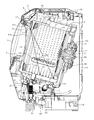
- FIG. 1 and FIG. 2 show the overall structure of a drum type washing machine.
- the outer box 1 of the drum type washing machine includes a base 1A made of synthetic resin and a box body 1B coupled to the base 1A.
- a laundry entrance / exit part 2 is formed at a substantially central part of the front face part (left side in FIG. 1) of the box body 1B.
- the door 3 has a double glass structure and opens and closes the laundry entrance / exit part 2.
- An operation panel 4 is provided on the upper portion of the front surface of the box body 1B.
- a control device 5 is provided on the back side of the operation panel 4 (inside the outer box 1).
- a bottomed cylindrical water tank 6 whose back side is closed is provided.
- the water tank 6 is elastically supported by the suspension 7 in the outer box 1 so that the central axis thereof is positioned on the axis that descends rearward (right side in FIG. 1).
- a washing machine motor 8 is provided outside the rear surface of the water tank 6.
- the washing machine motor 8 is composed of, for example, a DC brushless motor, is an outer rotor type, and includes a stator 8A and a rotor 8B.
- the stator 8 ⁇ / b> A is attached to the outside of the back surface of the water tank 6.
- the rotating shaft 8C at the center of the rotor 8B is supported by the bearing bracket 9 via the bearing 10 and is inserted into the water tank 6.
- a bottomed cylindrical drum 11 whose back side is closed is provided.
- the drum 11 is connected to the front end portion of the rotating shaft 8 ⁇ / b> C of the washing machine motor 8 at the center on the outer side of the back surface.
- the drum 11 is provided so as to be rotatable about the axis of the water tub 6, and is driven in the normal rotation direction and the reverse rotation direction by the washing machine motor 8.
- the washing machine motor 8 functions as a drive device that rotates the drum 11.
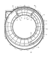
- a large number of holes 12 are formed in the peripheral wall (body portion) of the drum 11 over the entire area.
- the number of holes 12 ⁇ / b> A formed in the front half of the front side of the drum 11 (front half), i.e., the front side of the front and rear center of the drum 11, is equal to the number of holes 12 ⁇ / b> A. It is set to be larger than the number of holes 12 ⁇ / b> B formed in the rear half of the rear half of the drum 11, that is, the front and rear centers of the drum 11.
- a plurality of (for example, three) baffles 13 for picking up the laundry are provided at equal intervals along the circumferential direction of the drum 11 on the inner peripheral portion of the drum 11. The baffle 13 will be described in detail later.
- Both the drum 11 and the water tank 6 are open on the front side.
- a liquid-sealed rotary balancer 15 is provided inside the periphery of the opening 14 on the front side of the drum 11.
- a water tank cover 16 is attached to the opening on the front side of the water tank 6.
- the opening 16a at the tip of the water tank cover 16 is connected to the laundry entrance / exit 2 by a bellows 17 made of an annular elastic material (for example, rubber).
- a bellows 17 made of an annular elastic material (for example, rubber).
- a drain port 18 that is also used as a water intake port is formed at the bottom of the rear side of the water tank 6.
- One end of an in-machine drain hose 19 is connected to the drain port 18.
- the other end of the in-machine drain hose 19 is connected to the in-machine drain hose connection port 21 of the filter case 20 provided in the front part of the base 1 ⁇ / b> A of the outer box 1.
- the filter case 20 has an in-machine drain hose connection port portion 21 formed at the top, and a cap 22 attached to the front end portion.
- a lint filter (not shown) integral with the cap 22 is housed inside the filter case 20.
- a drain valve 23 is connected to the lower part of the filter case 20.
- a drain pipe 24 is connected to the outlet of the drain valve 23. The distal end of the drainage pipe 24 faces the outside of the machine from the base 1A of the outer box 1 and is connected to an outside drainage hose (not shown).
- a circulation pump 25 is provided at the rear end of the filter case 20.
- the circulation pump 25 sucks water in the water tank 6 (drum 11) through the drain port 18, the in-machine drain hose 19, and the filter case 20.
- the circulation pump 25 having the pump motor 25a shown in FIG. 11 has a discharge port portion 26 on the peripheral side portion (upper portion in the drawing).
- One end of a water supply hose 27 is connected to the discharge port portion 26.
- An intermediate portion of the water supply hose 27 extends upward from the circumferential side of the water tank cover 16, and a tip portion is connected to a water discharge mechanism portion 28 formed on the water tank cover 16.
- the water discharge mechanism 28 is configured to spray water into the drum 11.
- the circulation path 30 is formed so as to connect the drain port 18 and the water discharge mechanism 28. That is, the circulation path 30 is formed by the water tank 6, the drum 11, the drain port portion 18, the in-machine drain hose 19, the filter case 20, the water supply hose 27, and the water discharge mechanism portion 28.
- the circulation pump 25 is provided so as to be positioned in the circulation path 30. When the circulation pump 25 is driven, the water taken out from the drain port 18 of the water tank 6 is discharged (injected) from the water discharge mechanism 28 into the drum 11 in a shower shape.
- the air trap 31 is provided in the upper part of the front part of the filter case 20.
- the air trap 31 and the water level sensor 32 disposed at the top of the outer box 1 are connected by an air tube 33.
- the water level sensor 32 functions as a water level detection unit that detects the water level in the water tank 6 via the in-machine drain hose 19, the filter case 20, the air trap 31, and the air tube 33.
- a water supply valve 34 and a water supply case 35 are provided at the top of the outer box 1.
- An external water supply hose (not shown) connected to a water tap (not shown) is connected to the inlet of the water supply valve 34.
- One end of a connection pipe 36 is connected to the outlet of the water supply valve 34.
- the other end of the connection pipe 36 is connected to the water supply case 35.
- the water supply case 35 has a detergent storage part (not shown) inside.
- One end of an in-machine water supply hose 37 is connected to the water supply case 35.
- the other end of the in-machine water supply hose 37 is connected to the upper part of the water tank 6.
- the water supplied from the water supply via the water supply valve 34 is supplied into the water tank 6 via the connection pipe 36, the detergent storage part of the water supply case 35, and the in-machine water supply hose 37. Further, the water supply valve 34 and the water supply case 35 constitute a water supply device 38 for supplying water into the water tank 6.
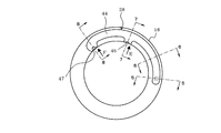
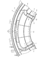
- the baffle 13 described above extends in the front-rear direction along the axis of the water tank 6 and protrudes toward the rotation center axis side of the drum 11.
- the baffle 13 has a mountain shape in which both side surfaces 13A and 13B in the circumferential direction rise toward the central ridge 13C.
- a plurality of holes 13D are formed in the central ridge portion 13C.
- the side surface portion 13A is a side surface portion on the clockwise direction side (for example, the direction of arrow A in FIGS. 2 and 3) when the drum type washing machine is viewed from the front.
- the side surface portion 13B is a side surface portion on the counterclockwise direction side (for example, the direction of arrow B in FIGS. 2 and 3) when the drum type washing machine is viewed from the front.
- the central ridge 13C of the baffle 13 has a curved shape like a sine wave when viewed from the plane direction. Specifically, when the central ridge portion 13C is divided into three regions arranged in the longitudinal direction, the central ridge portion 13C is separated from the first ridge portion 13Ca, the second ridge portion 13Cb, and the third ridge portion 13Cc. It is configured.
- the first protrusion 13Ca is positioned on one side in the circumferential direction with respect to the line L (see FIG. 3) along the axis of the water tub 6 (in this case, the arrow A direction side when the drum type washing machine is viewed from the front). And located on the front side of the drum 11.
- the second protrusion 13Cb is located on the other side in the circumferential direction with respect to the line L along the axis (in this case, the arrow B direction side when the drum type washing machine is viewed from the front), and the back surface of the drum 11 Located on the side.
- the third protrusion 13Cc is located between the first protrusion 13Ca and the second protrusion 13Cc. Further, the first protrusion 13Ca and the third protrusion 13Cc are connected by a smooth curve. The second protrusion 13Cb and the third protrusion 13Cc are also connected by a smooth curve.
- a first recess 13E is formed by the first protrusion 13Ca and the third protrusion 13Cc.
- the second protrusion 13Cb and the third protrusion 13Cc form a second recess 13F opposite to the first recess 13E.
- the first recess 13E is curved so that the lower side (counterclockwise side) is opened in FIG. 1, and the second recess 13F is curved so that the upper side (clockwise side) is opened in FIG.
- an air trap 39 communicating with the water tank 6 is provided at the upper part on the back side of the water tank 6.
- the air trap 39 and the foam sensor 40 disposed at the top of the outer box 1 are connected by an air tube 41.
- the foam sensor 40 comprises a pressure switch. Bubbles generated in the water tank 6 reach the air trap 39, and the bubbles expand and contract as the drum 11 rotates, whereby the pressure in the air trap 39 changes.
- the bubble sensor 40 detects the amount of bubbles generated by detecting the pressure change.
- the water discharge mechanism 28 includes protrusions 42 and 42 that are integrally formed on the outer peripheral portion of the upper part of the inner surface of the water tank cover 16, and these protrusions. And a closing plate 44 that is attached (welded) to the distal end portions of 42 and 42 to form a water channel 43.
- a connecting port portion 45 (see FIG. 5) that communicates with the water channel 43 is formed in a left portion (right portion in FIG. 4) of the water tank cover 16 in FIG. 2.
- a water supply hose 27 is connected to the connection port 45.
- a first water discharge port portion 46 see FIG.
- the first water discharge port portion 46 has a diffusion plate portion 46 a that faces the drum 11.
- the second water outlet part 47 together with the blocking plate 44 is provided. (See FIG. 8).
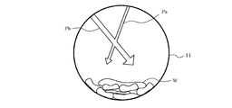
- the second water discharge port portion 47 has a diffusion plate portion 47 a that faces the drum 11. In this case, as shown in FIGS. 12 and 13, the first water outlet 46 and the second water outlet 47 are arranged such that the water falling point of the water discharge path Pa by the first water outlet 46 is within the drum 11.
- the second water outlet port 47 is set on the front side so that the water falling point of the water discharge path Pb by the second water outlet port 47 is on the back side of the water falling point of the first water outlet port 46.
- the first water discharge port portion 46 and the second water discharge port portion 47 are more open in the second water discharge port portion 47 than in the opening of the first water discharge port portion 46.
- the discharge flow rate of the second water discharge port 47 is set to be larger than the discharge flow rate of the first water discharge port 46.
- the second water outlet 47 is formed with a water passage hole 47 b for injecting washing water to the rear glass 3 a of the door 3. Bubbles adhering to the rear glass 3a of the door 3 are washed away by the water jetted from the water passage hole 47b of the second water outlet 47.
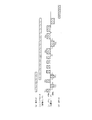
- FIG. 11 shows the electrical configuration of the drum type washing machine.
- the control device 5 is composed mainly of a microcomputer and controls the overall operation of the drum type washing machine.
- the control device 5 includes various operation signals from an operation unit 48 including various keys (switches) provided on the operation panel 4 (see FIG. 1), a water level detection signal from the water level sensor 32, and a bubble sensor 40.
- a current detection signal or the like from the transformer 51 is input.
- control apparatus 5 controls the water supply valve 34, the drain valve 23, the washing machine motor 8, and the pump motor 25a based on the said various input signals and the control program memorize
- the control device 5 controls the rotational speed of the washing machine motor 8 by a pulse width modulation (PWM) method using an inverter.
- PWM pulse width modulation
- the control device 5 displays the amount of detergent used according to the laundry weight detection described later on the display unit 52 provided on the operation panel 4 such as a liquid crystal panel.
- the control device 5 displays various information such as the set driving course, the remaining driving time, the reserved time, and the current time on the display unit 52.
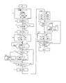
- the control device 5 starts (starts) the washing operation. Based on the signal output from the operation unit 48, the control device 5 first detects the weight of the laundry (clothing) (processing step S1 in FIG. 17).
- the laundry weight is detected by the time required for the rotational speed of the drum 11 to increase to a predetermined rotational speed, and thereafter, the drum 11 is driven by the washing machine motor 8 and the drum 11 is rotated by inertia. Is calculated from the time required for the rotational speed of the drum 11 to drop to a predetermined rotational speed. That is, the control device 5 detects the weight of the laundry with the rotational load of the washing machine motor 8. Thereafter, the control device 5 determines the amount of detergent, determines the water level in the washing process according to the laundry weight, and determines the rotation speed of the drum 11 based on the detection result of the laundry weight.
- the rotation sensor 49 that detects the rotation speed of the washing machine motor 8 functions as a weight detection unit that detects the weight of the laundry in the drum 11.
- the control apparatus 5 displays the determination result (detergent amount determined according to the laundry weight) on the display part 52 (process step S2 of FIG. 17).
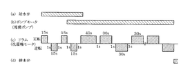
- the control device 5 detects the weight (load amount) of the laundry in three stages of small (for example, 1 kg), medium (for example, 3 kg), and large (for example, 6 kg). Then, the time charts of FIGS. 14, 15 and 16 are selected according to the detected stages.
- the control device 5 waits for a predetermined time (for example, 20 seconds) for the user to input the amount of detergent displayed on the water supply case 35 based on the amount of detergent displayed on the display unit 52 (determination step S3 in FIG. 17). Then, after a predetermined time has elapsed, the control device 5 opens the water supply valve 34 and supplies the tap water to the water level determined for the washing process (the water level where the laundry is immersed). In this case, it is assumed that an amount of detergent corresponding to the determination of the amount of detergent by the control device 5 is input in the detergent storage portion of the water supply case 35 in advance.
- the drum 11 is provided so as to be rotatable around the axis of the water tank 6 whose central axis descends rearward.
- the water to be supplied is collected on the back side (second half side) of the drum 11 (water tank 6) and becomes shallower toward the front side (front half side) of the drum 11. Therefore, there is almost no water in the vicinity of the front surface side (front end side portion) of the drum 11 or there is not much water.
- the control device 5 rotationally drives the drum 11 by the washing machine motor 8 at the start of water supply (see processing step S5 in FIG. 17, FIGS. 14C to 16C).
- the rotation cycle of the drum 11 at the start of water supply is such that the drum 11 is rotated at a low speed (for example, 40 to 60 rpm) in the forward rotation direction for 15 seconds, then the drum 11 is stopped for 1 second, The drum 11 is rotated at a low speed (for example, 40 to 60 rpm) in the reverse direction for 15 seconds, and then the drum 11 is stopped for 1 second.
- the control device 5 detects whether the bubble sensor 40 has detected a predetermined amount of bubbles. It is determined whether or not (determination step S7). Then, the control device 5 proceeds to the processing step S8 or the processing step S9 according to the determination result, and rotates the pump motor 25a to drive the circulation pump 25 (FIGS. 14B to 16). (See (b)).
- the control device 5 drives the circulation pump 25 by rotating the pump motor 25a at a set speed (for example, 2000 rpm) when the amount of bubbles detected by the bubble sensor 40 is less than the predetermined amount ("NO” in judgment step S7). (Processing step S8).
- the control device 5 changes the pump motor 25a from the current set speed (for example, 2000 rpm) to a constant speed (for example, 100 rpm).
- the circulation pump 25 is driven by rotating at a speed that is sequentially reduced (for example, 2000-100 rpm) (processing step S9).
- control device 5 observes the detected current value of the current transformer 51 and determines whether or not air is generated in the circulation pump 25 (determination step S10 in FIG. 17).
- the washing water in which the detergent is dissolved and supplied into the water tank 6 (in the drum 11) is stirred by the laundry washed up by the baffle 13 and dropped, and circulated by the circulation pump 25, thereby generating foam. become. If the generation of bubbles is excessive, not only the cleaning effect is lowered, but also the circulation pump 25 is damaged. When excessive bubbles are generated in the water tank 6 and the bubbles enter the circulation pump 25, the current value of the pump motor 25a greatly fluctuates as shown in FIG. It becomes constant. Thereby, the control device 5 determines whether air leakage has occurred in the circulation pump 25 (determination step S10 in FIG. 17).
- Step S10 in FIG. 17 the control speed of the pump motor 25a is reduced from the current setting speed by a constant speed (for example, 100 rpm).
- a constant speed for example, 100 rpm.
- the control device 5 determines whether or not the water level detected by the water level sensor 32 has reached the predetermined water level for the washing process set in the processing step S1. If not reached (“NO” in determination step S12), the control device 5 returns to determination step S7. On the other hand, when it has reached (“YES” in judgment step S12), the control device 5 closes the water supply valve 34 and stops water supply by the water supply valve 34 (processing step S13). Thereafter, the control device 5 drives the drum 11 in the forward direction and the reverse direction by the washing machine motor 8 to execute a substantial washing step (processing step S14).
- the control device 5 causes the drum 11 to rotate forward at a low speed (for example, 40 to 60 rpm) according to the time corresponding to the weight of the laundry. That is, when the weight of the laundry is small (for example, 1 kg), the control device 5 rotates the washing machine motor 8 forward for 20 seconds (see FIG. 14C), and the weight of the laundry is medium (for example, 3 kg). ), The washing machine motor 8 is rotated forward for 30 seconds (see FIG. 15C), and when the weight of the laundry is large (for example, 6 kg), the washing machine motor 8 is rotated forward for 40 seconds. (See FIG. 16 (c)).
- a low speed for example, 40 to 60 rpm
- control device 5 selects the rotation direction of the drum 11 as the normal rotation direction and changes the normal rotation time of the washing machine motor 8 according to the weight of the laundry. Thereby, the control device 5 changes the rotation amount of the drum 11.
- the control device 5 drives the circulation pump 25 during the washing process.
- the water in the water tank 6 is taken from the drain port part 18 of the water tank 6, and the first water outlet part 46 and the second water outlet part of the water discharge mechanism part 28 provided at the upper part of the opening part of the water tank 6. 47 is supplied in a shower shape toward the front side and the back side of the drum 11.
- control device 5 executes the determination step S15, the processing step S16, the determination step S17, and the processing step S18 similar to the above-described determination step S7, processing step S9, determination step S10, and processing step S11. Thereafter, the control device 5 performs a normal operation in which the washing machine motor 8 rotates normally for 30 seconds, stops for 1 second, reverses for 30 seconds, and stops for 1 second (processing step S19).
- the control device 5 determines whether or not the set time for the washing process has elapsed. When the time has not elapsed ("NO" in determination step S20), the control device 5 returns to determination step S15. On the other hand, when the time has elapsed (“YES” in determination step S20), the control device 5 opens the drain valve 23 to allow the water in the water tank 6 (drum 11) to flow from the drain port 18 of the water tank 6 to the in-machine drain hose. 19, The filter case 20 (lint filter), the drain valve 23, the drain pipe 24 and the drain hose outside the machine are discharged (processing step S21 in FIG. 17).
- the control device 5 executes a rinsing process.
- the control device 5 repeatedly performs the same water supply operation, rinsing operation, and draining operation as in the washing process.
- the control apparatus 5 performs a dehydration process.
- the control device 5 rotates the drum 11 in one direction at a high speed (for example, 700 to 1500 rpm) to perform centrifugal dehydration on the laundry.
- a high speed for example, 700 to 1500 rpm
- FIG. 12 and FIG. 13 show the state of the garment W that is the laundry at the initial stage of the washing process of the washing operation.
- the garment W moves from the front side to the rear side (in the direction of arrow Y shown in FIG. 3) along the side surface portion 13A of the baffle 13 while being scraped up by the baffle 13.
- the second recess 13F is formed on the back side of the baffle 13
- the garment W is not moved to the rear end side from the second recess 13F even if the drum 11 rotates. It fits in the 2nd recessed part 13F.
- the second recess 13 ⁇ / b> F is on the rear half side of the baffle 13.
- the garment W contained in the second recess 13F moves to the vicinity of the uppermost position in the drum 11 as the drum 11 rotates, it falls to the rear half of the drum 11 by its own weight and is washed. At this time, since a large amount of washing water is accumulated on the rear half side of the drum 11, it is easy for water to soak into the laundry W. In this case, it is set such that the amount of rotation (rotation time) of the drum 11 in the forward rotation direction increases as the amount (weight) of the clothing W increases. Therefore, as the amount (weight) of the garment W increases, the garment W is moved to the back side and falls to the back side where much washing water is accumulated.
- the detergent dissolves in water, and the washing water easily penetrates into the clothes W.
- the amount of water sprayed by the second water outlet 47 that sprays the back surface of the drum 11 is set larger than the amount of water discharged by the first water outlet 46 that sprays the front surface of the drum 11. Therefore, the washing water can be uniformly permeated into the entire clothing W.
- the clothing W that has been scraped with the rotation of the drum 11 falls along the water discharge direction (water discharge path Pb) by the second water discharge port portion 47 having a large water discharge amount. For this reason, it takes a long time for the clothes W to come into contact with the water discharged from the second water outlet 47, so that the clothes W can more easily soak.
- the garment W is scraped up by the baffle 13 and from the rear side along the side surface portion 13B of the baffle 13 (in the direction of arrow X shown in FIG. 3). Move to.
- the first concave portion 13E is formed on the front half side of the baffle 13, even if the drum 11 rotates, the clothing W is not moved to the front end portion than the first concave portion 13E. It fits in the 1st recessed part 13E.
- the first recess 13 ⁇ / b> E is on the front half side of the baffle 13.
- the water discharge mechanism portion 28 of the circulation path 30 includes a first water discharge port portion 46 that sprays water on the front side of the drum 11 and a second water discharge port portion 47 that sprays water on the back side in the drum 11. And.
- the water discharge amount of the second water discharge port portion 47 is set larger than the water discharge amount of the first water discharge port portion 46. Accordingly, the washing water can be uniformly permeated throughout the garment W that is moved so as to be unevenly distributed on the back side by the baffle 13, and the washing and rinsing operations can be performed sufficiently. It can be done efficiently.
- first water outlet 46 and the second water outlet 47 are such that the water falling point by the first water outlet 46 is the front side in the drum 11, and the water falls by the second water outlet 47.
- the point is configured to be closer to the back side than the water falling point by the first water outlet 46. Therefore, even if the laundry in the drum 11 tends to be unevenly distributed on the back side, the washing water can be uniformly permeated into the entire laundry. Further, it is possible to obtain the washing effect of the laundry more sufficiently, and the washing operation and the rinsing operation can be performed more efficiently.
- the amount of rotation (rotation time) of the drum 11 in the forward rotation direction is set to increase as the amount (weight) of the clothing W increases. Therefore, as the amount (weight) of the clothing W increases, the clothing W is moved to the back side in the drum 11 and falls to the back side where a lot of washing water is accumulated. Thereby, it is facilitated that the detergent dissolves in water, and the washing water easily penetrates into the clothes W. As shown in FIG. 18, the penetration rate of the washing water into the garment W becomes worse as the weight of the garment W increases. For this reason, increasing the forward rotation time as the weight of the garment W increases is effective in allowing the washing water to penetrate into the garment W.
- the control device 5 drives the circulation pump 25 by rotating the pump motor 25a at a speed obtained by sequentially subtracting a constant speed from the current set speed. In other words, the control device 5 reduces the amount of water circulated by the circulation pump 25 when the amount of bubbles detected by the bubble sensor 40 is greater than or equal to a predetermined amount. Thereby, it can prevent that a bubble generate
- control speed of the pump motor 25a is changed from the current set speed to a constant speed. Change to a reduced speed. That is, the control device 5 reduces the amount of water circulated by the circulation pump 25 when it is determined that air leakage has occurred in the circulation pump 25 based on the detected current value of the current transformer 51. Thereby, it is possible to prevent the circulation pump 25 from being damaged.
- control apparatus 5 is good to make the pump motor 25a stop when the rotation speed of the circulation pump 25 becomes below a lower limit by repeatedly performing judgment step S15 or judgment step S17. This prevents unnecessary continuation of control.
- FIG. 20 relates to the second embodiment, and the same parts as those in the first embodiment (FIG. 17) are denoted by the same reference numerals.
- the determination step S10, the processing step S11, the determination step S17, and the processing step S18 related to the current transformer 51 are deleted. That is, this embodiment has a configuration in which the current transformer 51 is omitted.
- FIG. 21 relates to the third embodiment, and the same components as those in the first embodiment (see FIGS. 14 to 16) are denoted by the same reference numerals.
- the forward rotation time (in this case) of the drum 11 set according to the weight of the laundry (in this case, small, medium, and large) in the initial stage of the washing process. , 20 seconds, 30 seconds, 40 seconds) is divided into a plurality of forward rotation times and stop times. According to this structure, generation
- FIGS. 22 and 23 show the entire structure of the drum type washing machine.
- the drum type washing machine has the same basic configuration, although the outer box 1 has a different shape from the above-described drum type washing machine (see FIGS. 1 and 2).
- the configuration of the water discharge mechanism 28 will be described with reference to FIGS.
- arc-shaped water channel forming ridges 62 and 63 having a predetermined distance from the lower part to the upper half part are integrally formed on the outer peripheral part of the back surface of the synthetic resin water tank cover 61. It is molded into. These protrusions 62 and 63 are connected at the lower part.
- the back surface of the aquarium cover 61 In the upper part of the back surface of the aquarium cover 61, at the position shifted in the clockwise direction in FIG. 64 and 65 are integrally formed so as to be directed to the center of the water tank cover 61.
- the ridges 64 and 65 communicate with each other between the ridges 62 and 63.
- the second nozzle part is formed at a position shifted counterclockwise in FIG.
- the protrusions 66 and 67 are integrally formed so as to be oriented toward the center of the water tank cover 61.
- the protrusions 66 and 67 communicate with each other between the protrusions 62 and 63.
- the water injection cover 68 made of synthetic resin has an arc shape like the ridges 62 and 63 of the water tank cover 61.
- ridge portions 69 and 70 for forming water channels corresponding to the ridge portions 62 and 63 are integrally formed. These ridges 69 and 70 are connected at the lower part.
- the water injection cover 68 has a first nozzle portion forming protrusions 71 and 72 corresponding to the protrusions 64 and 65 and a second nozzle portion forming corresponding to the protrusions 66 and 67.
- the ridge portions 73 and 74 are integrally formed.
- the opening part 61a of the front surface of the water tank cover 61 is watertightly connected with the laundry entrance / exit part 2 by the bellows 17 (refer FIG. 22).
- the water injection cover 68 is disposed on the back side of the water tank cover 61.
- the protrusions 69 and 70 are abutted with the protrusions 62 and 63
- the protrusions 71 and 72 are abutted with the protrusions 64 and 65
- the protrusions 73 and 74 are abutted with the protrusion 66. , 67.
- These are ultrasonically welded, for example, to form the water channel 75, the first nozzle portion 76, and the second nozzle portion 77 shown in FIGS. 26 and 29 to 32.
- the water discharge mechanism part 28 is comprised.
- the state into which the water injection cover 68 was welded is shown for convenience of explanation.
- the first nozzle portion 76 includes a base wall portion 76a that is oriented obliquely downward from above, and a guide wall portion 76b that corresponds to the base wall portion 76a. These base wall portions 76a and guide wall portions 76b are constituted by both side wall portions 76c and 76d that connect both side portions. With this configuration, the first nozzle portion 76 forms a substantially horizontally long rectangular shape (slit shape) opening 76 f facing the drum 11.
- the water discharge flow rate of the first nozzle part 76 is set by the minimum distance dimension Sa between the base wall part 76a and the guide wall part 76b corresponding to the base wall part 76a.
- the water drop point of the water discharge path Pa by the first nozzle portion 76 is set by an inclination angle ⁇ which is a directivity angle of the base wall portion 76a and the guide wall portion 76b.
- the second nozzle part 77 includes a base wall part 77a oriented obliquely downward from above, and a guide wall part 77b corresponding to the base wall part 77a,
- the base wall portion 77a and the guide wall portion 77b are constituted by both side wall portions 77c and 77d that connect both side portions.
- the second nozzle portion 77 forms a substantially horizontally long rectangular shape (slit shape) opening 77f that faces the drum 11.
- the water discharge flow rate of the second nozzle part 77 is set by the minimum distance dimension Sb between the base wall part 77a and the guide wall part 77b corresponding to the base wall part 77a.
- the interval dimension Sb is set to be larger than the interval dimension Sa of the first nozzle portion 76 (Sb> Sa). Furthermore, the water drop point of the water discharge path Pb by the second nozzle part 77 is set by an inclination angle ⁇ that is a directivity angle of the base wall part 77a and the guide wall part 77b. The inclination angle ⁇ is set to be larger than the inclination angle ⁇ of the first nozzle portion 76 ( ⁇ > ⁇ ). As shown in FIG. 33, a connecting port portion 78 that communicates with the water channel 75 is formed in a left portion (right portion in FIG. 27) of the water tank cover 61 from directly below in FIG. 23. A water supply hose 27 is connected to the water channel 75.
- the control device 5 drives the circulation pump 25 so that the water in the water tank 6 taken from the drain port 18 of the water tank 6 is supplied to the water discharge mechanism 28 at the upper part of the opening of the water tank 6.
- the first nozzle portion 76 and the second nozzle portion 77 are discharged so as to be ejected toward the front side and the rear side of the drum 11.
- the control device 5 performs a draining operation and a dehydrating operation, and ends the washing process.
- the control apparatus 5 performs a rinse process and a dehydration process further, and complete
- the water discharge mechanism 28 of the circulation path 30 welds the water injection cover 68 to the back surface of the water tank cover 61 by ultrasonic waves, thereby supplying the water path 75 to which the wash water from the circulation path 30 is supplied.
- the first nozzle portion 76 and the second nozzle portion 77 are formed so as to discharge the washing water from the water channel 75 into the drum 11. Therefore, not only a pipe such as a conventional external hose is unnecessary, but also a pipe that protrudes into the inlet / outlet portion 61b of the water tank cover 61 such as a conventional deflection plate can be eliminated. In this way, anything that obstructs the entry and exit of clothing can be eliminated.
- the water discharge mechanism 28 is composed of two members, a water tank cover 61 and a water injection cover 68. Therefore, the number of parts is small and the structure is simple. And since it was set as the structure which welds the water injection cover 68 to the water tank cover 61, after welding, it can handle as one component and an assembly is easy.
- the first nozzle portion 76 includes a base wall portion 76a directed obliquely downward from above, a guide wall portion 76b corresponding to the base wall portion 76a, and both sides of the base wall portion 76a and the guide wall portion 76b. It is comprised by the both side wall parts 76c and 76d which connect a part. With this configuration, the first nozzle portion 76 forms a substantially horizontally long (slit-shaped) opening 76 f that faces the drum 11.
- the second nozzle portion 77 includes a base wall portion 77a oriented obliquely downward from above, a guide wall portion 77b corresponding to the base wall portion 77a, and both sides of the base wall portion 77a and the guide wall portion 77b.
- the second nozzle portion 77 forms a substantially horizontally long rectangular shape (slit shape) opening 77 f that faces the drum 11. Accordingly, the spray water from the first nozzle part 76 and the second nozzle part 77 is in a state of spreading horizontally and in a film shape, unlike the conventional scattered water from the deflecting plate. Thereby, washing water can be uniformly permeated into clothing.
- the spray water from the 1st nozzle part 76 and the 2nd nozzle part 77 will be in the state which spreads in the shape of a horizontal film
- the water falling point of the water discharge path Pa by the first nozzle portion 76 is set by the inclination angle ⁇ which is the directivity angle of the base wall portion 76a and the guide wall portion 76b.
- the water falling point of the water discharge path Pb by the second nozzle part 77 is set by the inclination angle ⁇ which is the directivity angle of the base wall part 77a and the guide wall part 77b.
- the inclination angle ⁇ is set larger than the inclination angle ⁇ of the first nozzle portion 76 ( ⁇ > ⁇ ).
- the first nozzle portion 76 discharges water toward the front side of the drum 11, and the second nozzle portion 77 discharges water toward the back side of the drum 11.
- the amount of water discharged by the second nozzle portion 77 is made larger than the amount of water discharged by the first nozzle portion 76. Therefore, the washing water can be uniformly permeated throughout the clothes moved so as to be unevenly distributed on the back side by the baffle 13, and the washing and rinsing operations can be efficiently performed. It can be carried out.
- (Fifth embodiment) 34 and 35 relate to the fifth embodiment, and the same reference numerals are given to the same portions as those in the fourth embodiment described above.
- the first nozzle portion 76 and the second nozzle portion 77 are formed by both the water tank cover 61 and the water injection cover 68.
- a first nozzle portion 81 that replaces the first nozzle portion 76 is formed integrally with the water injection cover 68.
- a second nozzle portion 82 instead of the second nozzle portion 77 is formed integrally with the water injection cover 68.
- the water channel from the connection port part 78 to each nozzle part is formed by both the water tank cover 61 and the water injection cover 68. According to the fifth embodiment, the same effect as that of the fourth embodiment can be obtained.
- the present embodiment is not limited to the embodiment described above and shown in the drawings, and the following modifications and expansions are possible.
- a normal linear baffle may be used.
- the number of baffles 13 may be other than three.
- the rotation amount of the drum 11 is changed by changing the normal rotation time of the drum 11 in accordance with the weight of the laundry at the initial stage of the washing process.
- the amount of rotation of the drum 11 may be changed by changing the normal rotation speed of the drum 11.
- the control device 5 controls the “rotation direction” of the drum 11 by the washing machine motor 8 so that the laundry W falls to the water dropping point side by the second water discharge port portion 47 having a large water discharge amount at the initial stage of the washing operation.
- the “rotation speed” of the drum 11 by the washing machine motor 8 may be controlled so that the laundry W falls to the water drop point side by the second water discharge port portion 47 having a large water discharge amount.
- the control device 5 rotates the drum 11 by the washing machine motor 8 so that the laundry W falls along the water discharge direction (water discharge path Pb) by the second water discharge port 47 having a large water discharge amount.
- the direction may be controlled.
- the falling laundry W collides with the water discharged from the second water outlet 47, and the mechanical power easily penetrates into the fibers of the laundry W. Therefore, it is possible to easily remove the dirt attached to the laundry W.
- a configuration using a current sensor as the weight detection means is very good.
- the control device 5 drives the drum based on the magnitude of the current detected by the current sensor when the drum 11 is rotated by driving the washing machine motor 8 and the data recorded in the control device 5 in advance. You may make it judge the weight of the laundry accommodated in 11.
- the number of water outlets or nozzles provided in the water discharge mechanism 28 is not limited to two, and may be, for example, one or three or more. This embodiment can also be applied to a drum-type washing machine with a drying function.
- the above-described embodiments are presented as examples, and are not intended to limit the scope of the invention.
- 1 is an outer box
- 5 is a control device (control means)
- 6 is a water tank
- 8 is a washing machine motor
- 11 is a drum
- 13 is a baffle
- 16 is a water tank cover
- 18 is a drain port (water intake port)
- 25 is A circulation pump
- 25a is a pump motor
- 28 is a water discharge mechanism
- 30 is a circulation route
- 43 is a water channel
- 68 is a water injection cover
- 46 is a first water discharge port
- 47 is a second water discharge port
- 61 is a water tank cover.
- 75 is a water channel
- 76 is a first nozzle part
- 76a is a base wall part
- 76b is a guide wall part
- 76c and 76d are side wall parts
- 76f is an opening
- 77 is a second nozzle part
- 77a is a base wall part
- 77b is a guide wall portion
- 77c and 77d are side wall portions
- 77f is an opening
- 81 is a first nozzle portion
- 82 is a second nozzle portion.
Priority Applications (3)
| Application Number | Priority Date | Filing Date | Title |
|---|---|---|---|
| EP10811662.5A EP2471993B1 (en) | 2009-08-24 | 2010-08-02 | Drum type washing machine |
| KR1020127005202A KR101389238B1 (ko) | 2009-08-24 | 2010-08-02 | 드럼식 세탁기 |
| CN201080037439.1A CN102482833B (zh) | 2009-08-24 | 2010-08-02 | 滚筒式洗衣机 |
Applications Claiming Priority (4)
| Application Number | Priority Date | Filing Date | Title |
|---|---|---|---|
| JP2009193046A JP5489328B2 (ja) | 2009-08-24 | 2009-08-24 | ドラム式洗濯機 |
| JP2009-193046 | 2009-08-24 | ||
| JP2009210415A JP5279670B2 (ja) | 2009-09-11 | 2009-09-11 | ドラム式洗濯機 |
| JP2009-210415 | 2009-09-11 |
Publications (1)
| Publication Number | Publication Date |
|---|---|
| WO2011024611A1 true WO2011024611A1 (ja) | 2011-03-03 |
Family
ID=43627721
Family Applications (1)
| Application Number | Title | Priority Date | Filing Date |
|---|---|---|---|
| PCT/JP2010/063018 WO2011024611A1 (ja) | 2009-08-24 | 2010-08-02 | ドラム式洗濯機 |
Country Status (4)
| Country | Link |
|---|---|
| EP (1) | EP2471993B1 (ko) |
| KR (1) | KR101389238B1 (ko) |
| CN (1) | CN102482833B (ko) |
| WO (1) | WO2011024611A1 (ko) |
Cited By (5)
| Publication number | Priority date | Publication date | Assignee | Title |
|---|---|---|---|---|
| CN102888740A (zh) * | 2011-07-22 | 2013-01-23 | 博西华电器(江苏)有限公司 | 洗衣机的排水装置以及具有该排水装置的洗衣机 |
| CN103547726A (zh) * | 2011-04-14 | 2014-01-29 | Lg电子株式会社 | 洗衣机 |
| WO2015133845A1 (en) * | 2014-03-05 | 2015-09-11 | Lg Electronics Inc. | Washing machine and control method of the same |
| JP2018042622A (ja) * | 2016-09-12 | 2018-03-22 | 日立アプライアンス株式会社 | 洗濯機 |
| CN110352274A (zh) * | 2016-12-28 | 2019-10-18 | Lg电子株式会社 | 洗衣机 |
Families Citing this family (20)
| Publication number | Priority date | Publication date | Assignee | Title |
|---|---|---|---|---|
| JP5799200B2 (ja) * | 2011-02-23 | 2015-10-21 | パナソニックIpマネジメント株式会社 | ドラム式洗濯機 |
| ES2587267T3 (es) * | 2012-07-30 | 2016-10-21 | Whirlpool Corporation | Método para controlar la velocidad de un tambor giratorio de una máquina de lavar ropa de eje horizontal y máquina de lavar que usa tal método |
| ITTO20121049A1 (it) * | 2012-12-05 | 2014-06-06 | Indesit Co Spa | Lavabiancheria con circuito di protezione |
| CN104018313B (zh) * | 2013-02-28 | 2017-09-26 | 天津日日新资产管理有限公司 | 洗衣机控制方法及洗衣机 |
| CN104074031B (zh) * | 2013-03-30 | 2018-03-30 | 青岛海尔洗衣机有限公司 | 一种具有喷淋外桶盖的洗衣机 |
| KR102210011B1 (ko) * | 2013-09-05 | 2021-02-01 | 삼성전자주식회사 | 세탁기 및 그 제어방법 |
| JP6286311B2 (ja) * | 2014-07-29 | 2018-02-28 | シャープ株式会社 | ドラム式洗濯機 |
| KR102196183B1 (ko) * | 2014-10-27 | 2020-12-29 | 엘지전자 주식회사 | 세탁물 처리기기 및 그 제어방법 |
| JP6603042B2 (ja) * | 2015-05-25 | 2019-11-06 | 東芝ライフスタイル株式会社 | 洗濯機 |
| US10422068B2 (en) | 2016-02-12 | 2019-09-24 | Whirlpool Corporation | Laundry treating appliance and methods of operation |
| KR101756408B1 (ko) * | 2016-04-18 | 2017-07-11 | 엘지전자 주식회사 | 배수펌프 구동장치, 및 이를 구비한 세탁물 처리기기 |
| KR102573125B1 (ko) * | 2017-12-28 | 2023-08-30 | 엘지전자 주식회사 | 세탁기 |
| EP3505666B1 (en) * | 2017-12-28 | 2021-08-11 | LG Electronics Inc. | Method for controlling washing machine |
| CN110387699B (zh) * | 2018-04-16 | 2021-10-29 | 青岛海尔洗涤电器有限公司 | 滚筒洗衣机及其喷淋系统 |
| CN108755000B (zh) * | 2018-04-27 | 2023-04-25 | 无锡小天鹅电器有限公司 | 滚筒洗衣机及其控制方法 |
| CN110607635B (zh) * | 2018-06-15 | 2022-06-17 | 青岛海尔洗涤电器有限公司 | 滚筒洗衣机的喷淋控制方法 |
| KR20200001496A (ko) | 2018-06-27 | 2020-01-06 | 엘지전자 주식회사 | 세탁기 |
| WO2020004905A1 (en) | 2018-06-27 | 2020-01-02 | Lg Electronics Inc. | Washing machine |
| WO2020004908A1 (en) * | 2018-06-27 | 2020-01-02 | Lg Electronics Inc. | Washing machine |
| WO2020004911A1 (en) | 2018-06-27 | 2020-01-02 | Lg Electronics Inc. | Washing machine |
Citations (6)
| Publication number | Priority date | Publication date | Assignee | Title |
|---|---|---|---|---|
| JPH07171288A (ja) * | 1993-12-17 | 1995-07-11 | Sharp Corp | ドラム式洗濯機および洗濯方法 |
| JPH09215891A (ja) | 1996-02-15 | 1997-08-19 | Matsushita Electric Ind Co Ltd | 洗濯機 |
| JP2006192249A (ja) * | 2005-01-10 | 2006-07-27 | Lg Electronics Inc | ドラム洗濯機 |
| JP2006239141A (ja) * | 2005-03-03 | 2006-09-14 | Sharp Corp | ドラム式洗濯機 |
| JP2008113982A (ja) | 2006-11-08 | 2008-05-22 | Hitachi Appliances Inc | 洗濯機 |
| JP2009056113A (ja) * | 2007-08-31 | 2009-03-19 | Toshiba Corp | 洗濯機 |
Family Cites Families (10)
| Publication number | Priority date | Publication date | Assignee | Title |
|---|---|---|---|---|
| US3388410A (en) * | 1967-09-11 | 1968-06-18 | Donald E. Marshall | Cleaning apparatus and method |
| DE3825500A1 (de) * | 1988-07-27 | 1990-02-08 | Licentia Gmbh | Verfahren zur steuerung des laugen-abpumpvorgangs bei waschmaschinen |
| DE3825502A1 (de) * | 1988-07-27 | 1990-02-01 | Licentia Gmbh | Verfahren und vorrichtung zur steuerung des laugen-abpumpvorgangs bei waschmaschinen |
| DE4236873A1 (de) * | 1992-10-31 | 1994-05-05 | Harald Faller | Verfahren zum Waschen von Wäsche und nach dem Verfahren arbeitende Waschmaschine |
| BE1009718A6 (nl) * | 1995-10-20 | 1997-07-01 | Peeters Tom Walter | Wasmachine. |
| DE19962257B4 (de) * | 1999-12-22 | 2013-11-28 | BSH Bosch und Siemens Hausgeräte GmbH | Wäschebehandlungsmaschine |
| KR100393994B1 (ko) * | 2000-10-19 | 2003-08-09 | 엘지전자 주식회사 | 세탁기의 세탁수 재순환 장치 |
| DE10227958A1 (de) * | 2002-06-22 | 2004-01-08 | Electrolux Home Products Corporation N.V. | Waschmaschine |
| KR20050121052A (ko) * | 2004-06-21 | 2005-12-26 | 삼성전자주식회사 | 세탁기 |
| EP2009165A1 (en) * | 2007-06-28 | 2008-12-31 | Bonferraro S.p.A. | Operating cycle for the drain pump of a household washing appliance |
-
2010
- 2010-08-02 KR KR1020127005202A patent/KR101389238B1/ko active IP Right Grant
- 2010-08-02 EP EP10811662.5A patent/EP2471993B1/en active Active
- 2010-08-02 WO PCT/JP2010/063018 patent/WO2011024611A1/ja active Application Filing
- 2010-08-02 CN CN201080037439.1A patent/CN102482833B/zh active Active
Patent Citations (6)
| Publication number | Priority date | Publication date | Assignee | Title |
|---|---|---|---|---|
| JPH07171288A (ja) * | 1993-12-17 | 1995-07-11 | Sharp Corp | ドラム式洗濯機および洗濯方法 |
| JPH09215891A (ja) | 1996-02-15 | 1997-08-19 | Matsushita Electric Ind Co Ltd | 洗濯機 |
| JP2006192249A (ja) * | 2005-01-10 | 2006-07-27 | Lg Electronics Inc | ドラム洗濯機 |
| JP2006239141A (ja) * | 2005-03-03 | 2006-09-14 | Sharp Corp | ドラム式洗濯機 |
| JP2008113982A (ja) | 2006-11-08 | 2008-05-22 | Hitachi Appliances Inc | 洗濯機 |
| JP2009056113A (ja) * | 2007-08-31 | 2009-03-19 | Toshiba Corp | 洗濯機 |
Cited By (11)
| Publication number | Priority date | Publication date | Assignee | Title |
|---|---|---|---|---|
| CN103547726A (zh) * | 2011-04-14 | 2014-01-29 | Lg电子株式会社 | 洗衣机 |
| EP2698467A2 (en) * | 2011-04-14 | 2014-02-19 | Lg Electronics Inc. | Washer |
| EP2698467A4 (en) * | 2011-04-14 | 2015-04-22 | Lg Electronics Inc | WASHER |
| CN103547726B (zh) * | 2011-04-14 | 2016-07-13 | Lg电子株式会社 | 洗衣机 |
| US9394644B2 (en) | 2011-04-14 | 2016-07-19 | Lg Electronics Inc. | Washer |
| US9765465B2 (en) | 2011-04-14 | 2017-09-19 | Lg Electronics Inc. | Washer |
| CN102888740A (zh) * | 2011-07-22 | 2013-01-23 | 博西华电器(江苏)有限公司 | 洗衣机的排水装置以及具有该排水装置的洗衣机 |
| WO2015133845A1 (en) * | 2014-03-05 | 2015-09-11 | Lg Electronics Inc. | Washing machine and control method of the same |
| JP2018042622A (ja) * | 2016-09-12 | 2018-03-22 | 日立アプライアンス株式会社 | 洗濯機 |
| CN110352274A (zh) * | 2016-12-28 | 2019-10-18 | Lg电子株式会社 | 洗衣机 |
| US11920278B2 (en) | 2016-12-28 | 2024-03-05 | Lg Electronics Inc. | Washing machine |
Also Published As
| Publication number | Publication date |
|---|---|
| KR101389238B1 (ko) | 2014-04-24 |
| EP2471993B1 (en) | 2019-10-30 |
| EP2471993A1 (en) | 2012-07-04 |
| KR20120037032A (ko) | 2012-04-18 |
| CN102482833A (zh) | 2012-05-30 |
| CN102482833B (zh) | 2014-07-30 |
| EP2471993A4 (en) | 2013-03-13 |
Similar Documents
| Publication | Publication Date | Title |
|---|---|---|
| WO2011024611A1 (ja) | ドラム式洗濯機 | |
| JP5489328B2 (ja) | ドラム式洗濯機 | |
| JP5279670B2 (ja) | ドラム式洗濯機 | |
| KR20170099150A (ko) | 세탁기 및 그 제어방법 | |
| JP2983161B2 (ja) | 噴射ノズル組立体を具備した洗濯機 | |
| JP2012070810A (ja) | ドラム式洗濯乾燥機 | |
| EP2128322B1 (en) | Washing machine and method of washing drum | |
| JP6286311B2 (ja) | ドラム式洗濯機 | |
| JP5719955B2 (ja) | 洗濯機 | |
| TWI444518B (zh) | Drum Washing Machine (1) | |
| JP6071854B2 (ja) | ドラム式洗濯機 | |
| JP6158397B2 (ja) | ドラム式洗濯機 | |
| JP5889575B2 (ja) | 洗濯機 | |
| JP6139574B2 (ja) | ドラム式洗濯機 | |
| JP6732867B2 (ja) | ドラム式洗濯機 | |
| JP7032480B2 (ja) | ドラム式洗濯機 | |
| JP5253488B2 (ja) | 洗濯機 | |
| JP7097546B2 (ja) | 洗濯機 | |
| JP6718411B2 (ja) | ドラム式洗濯機 | |
| WO2023066274A1 (zh) | 滚筒洗衣机 | |
| JP6415858B2 (ja) | 洗濯機 | |
| WO2023066275A1 (zh) | 滚筒洗衣机 | |
| JP2011056112A (ja) | ドラム式洗濯機 | |
| KR102477943B1 (ko) | 세탁기의 제어방법 | |
| WO2020020268A1 (zh) | 立式洗衣机 |
Legal Events
| Date | Code | Title | Description |
|---|---|---|---|
| WWE | Wipo information: entry into national phase |
Ref document number: 201080037439.1 Country of ref document: CN |
|
| 121 | Ep: the epo has been informed by wipo that ep was designated in this application |
Ref document number: 10811662 Country of ref document: EP Kind code of ref document: A1 |
|
| WWE | Wipo information: entry into national phase |
Ref document number: 2010811662 Country of ref document: EP |
|
| NENP | Non-entry into the national phase |
Ref country code: DE |
|
| WWE | Wipo information: entry into national phase |
Ref document number: 1201000635 Country of ref document: TH |
|
| ENP | Entry into the national phase |
Ref document number: 20127005202 Country of ref document: KR Kind code of ref document: A |