WO2011007835A1 - 車両運転支援装置と車両運転支援方法 - Google Patents
車両運転支援装置と車両運転支援方法 Download PDFInfo
- Publication number
- WO2011007835A1 WO2011007835A1 PCT/JP2010/061986 JP2010061986W WO2011007835A1 WO 2011007835 A1 WO2011007835 A1 WO 2011007835A1 JP 2010061986 W JP2010061986 W JP 2010061986W WO 2011007835 A1 WO2011007835 A1 WO 2011007835A1
- Authority
- WO
- WIPO (PCT)
- Prior art keywords
- obstacle
- control
- overtaking
- unit
- host vehicle
- Prior art date
Links
- 238000000034 method Methods 0.000 title claims description 56
- 238000001514 detection method Methods 0.000 claims abstract description 242
- 238000013459 approach Methods 0.000 claims description 159
- 230000002265 prevention Effects 0.000 claims description 153
- 230000001629 suppression Effects 0.000 claims description 54
- 238000004364 calculation method Methods 0.000 claims description 46
- 238000012545 processing Methods 0.000 claims description 27
- 230000001133 acceleration Effects 0.000 claims description 11
- 230000033001 locomotion Effects 0.000 claims description 7
- 238000004904 shortening Methods 0.000 claims description 2
- 239000012530 fluid Substances 0.000 description 47
- 238000003384 imaging method Methods 0.000 description 22
- 238000010586 diagram Methods 0.000 description 15
- 238000006073 displacement reaction Methods 0.000 description 14
- 230000007935 neutral effect Effects 0.000 description 10
- 230000007423 decrease Effects 0.000 description 9
- 238000005304 joining Methods 0.000 description 9
- 238000012937 correction Methods 0.000 description 7
- 238000006243 chemical reaction Methods 0.000 description 6
- 238000002474 experimental method Methods 0.000 description 6
- 230000000694 effects Effects 0.000 description 5
- 239000003550 marker Substances 0.000 description 5
- 238000012986 modification Methods 0.000 description 5
- 230000004048 modification Effects 0.000 description 5
- 101100109110 Danio rerio aph1b gene Proteins 0.000 description 3
- 238000002347 injection Methods 0.000 description 3
- 239000007924 injection Substances 0.000 description 3
- 230000006854 communication Effects 0.000 description 2
- 230000003111 delayed effect Effects 0.000 description 2
- 238000003860 storage Methods 0.000 description 2
- 230000005540 biological transmission Effects 0.000 description 1
- 238000004891 communication Methods 0.000 description 1
- 238000009826 distribution Methods 0.000 description 1
- 239000000446 fuel Substances 0.000 description 1
- 230000005484 gravity Effects 0.000 description 1
- 238000009434 installation Methods 0.000 description 1
- 238000005070 sampling Methods 0.000 description 1
- 230000002123 temporal effect Effects 0.000 description 1
Images


Classifications
-
- B—PERFORMING OPERATIONS; TRANSPORTING
- B60—VEHICLES IN GENERAL
- B60T—VEHICLE BRAKE CONTROL SYSTEMS OR PARTS THEREOF; BRAKE CONTROL SYSTEMS OR PARTS THEREOF, IN GENERAL; ARRANGEMENT OF BRAKING ELEMENTS ON VEHICLES IN GENERAL; PORTABLE DEVICES FOR PREVENTING UNWANTED MOVEMENT OF VEHICLES; VEHICLE MODIFICATIONS TO FACILITATE COOLING OF BRAKES
- B60T8/00—Arrangements for adjusting wheel-braking force to meet varying vehicular or ground-surface conditions, e.g. limiting or varying distribution of braking force
- B60T8/17—Using electrical or electronic regulation means to control braking
- B60T8/1755—Brake regulation specially adapted to control the stability of the vehicle, e.g. taking into account yaw rate or transverse acceleration in a curve
- B60T8/17558—Brake regulation specially adapted to control the stability of the vehicle, e.g. taking into account yaw rate or transverse acceleration in a curve specially adapted for collision avoidance or collision mitigation
-
- B—PERFORMING OPERATIONS; TRANSPORTING
- B60—VEHICLES IN GENERAL
- B60K—ARRANGEMENT OR MOUNTING OF PROPULSION UNITS OR OF TRANSMISSIONS IN VEHICLES; ARRANGEMENT OR MOUNTING OF PLURAL DIVERSE PRIME-MOVERS IN VEHICLES; AUXILIARY DRIVES FOR VEHICLES; INSTRUMENTATION OR DASHBOARDS FOR VEHICLES; ARRANGEMENTS IN CONNECTION WITH COOLING, AIR INTAKE, GAS EXHAUST OR FUEL SUPPLY OF PROPULSION UNITS IN VEHICLES
- B60K35/00—Instruments specially adapted for vehicles; Arrangement of instruments in or on vehicles
- B60K35/20—Output arrangements, i.e. from vehicle to user, associated with vehicle functions or specially adapted therefor
- B60K35/28—Output arrangements, i.e. from vehicle to user, associated with vehicle functions or specially adapted therefor characterised by the type of the output information, e.g. video entertainment or vehicle dynamics information; characterised by the purpose of the output information, e.g. for attracting the attention of the driver
-
- B—PERFORMING OPERATIONS; TRANSPORTING
- B60—VEHICLES IN GENERAL
- B60T—VEHICLE BRAKE CONTROL SYSTEMS OR PARTS THEREOF; BRAKE CONTROL SYSTEMS OR PARTS THEREOF, IN GENERAL; ARRANGEMENT OF BRAKING ELEMENTS ON VEHICLES IN GENERAL; PORTABLE DEVICES FOR PREVENTING UNWANTED MOVEMENT OF VEHICLES; VEHICLE MODIFICATIONS TO FACILITATE COOLING OF BRAKES
- B60T7/00—Brake-action initiating means
- B60T7/12—Brake-action initiating means for automatic initiation; for initiation not subject to will of driver or passenger
- B60T7/22—Brake-action initiating means for automatic initiation; for initiation not subject to will of driver or passenger initiated by contact of vehicle, e.g. bumper, with an external object, e.g. another vehicle, or by means of contactless obstacle detectors mounted on the vehicle
-
- G—PHYSICS
- G08—SIGNALLING
- G08G—TRAFFIC CONTROL SYSTEMS
- G08G1/00—Traffic control systems for road vehicles
- G08G1/16—Anti-collision systems
- G08G1/166—Anti-collision systems for active traffic, e.g. moving vehicles, pedestrians, bikes
-
- G—PHYSICS
- G08—SIGNALLING
- G08G—TRAFFIC CONTROL SYSTEMS
- G08G1/00—Traffic control systems for road vehicles
- G08G1/16—Anti-collision systems
- G08G1/167—Driving aids for lane monitoring, lane changing, e.g. blind spot detection
-
- B—PERFORMING OPERATIONS; TRANSPORTING
- B60—VEHICLES IN GENERAL
- B60K—ARRANGEMENT OR MOUNTING OF PROPULSION UNITS OR OF TRANSMISSIONS IN VEHICLES; ARRANGEMENT OR MOUNTING OF PLURAL DIVERSE PRIME-MOVERS IN VEHICLES; AUXILIARY DRIVES FOR VEHICLES; INSTRUMENTATION OR DASHBOARDS FOR VEHICLES; ARRANGEMENTS IN CONNECTION WITH COOLING, AIR INTAKE, GAS EXHAUST OR FUEL SUPPLY OF PROPULSION UNITS IN VEHICLES
- B60K2360/00—Indexing scheme associated with groups B60K35/00 or B60K37/00 relating to details of instruments or dashboards
- B60K2360/16—Type of output information
- B60K2360/179—Distances to obstacles or vehicles
-
- B—PERFORMING OPERATIONS; TRANSPORTING
- B60—VEHICLES IN GENERAL
- B60T—VEHICLE BRAKE CONTROL SYSTEMS OR PARTS THEREOF; BRAKE CONTROL SYSTEMS OR PARTS THEREOF, IN GENERAL; ARRANGEMENT OF BRAKING ELEMENTS ON VEHICLES IN GENERAL; PORTABLE DEVICES FOR PREVENTING UNWANTED MOVEMENT OF VEHICLES; VEHICLE MODIFICATIONS TO FACILITATE COOLING OF BRAKES
- B60T2201/00—Particular use of vehicle brake systems; Special systems using also the brakes; Special software modules within the brake system controller
- B60T2201/08—Lane monitoring; Lane Keeping Systems
-
- B—PERFORMING OPERATIONS; TRANSPORTING
- B60—VEHICLES IN GENERAL
- B60T—VEHICLE BRAKE CONTROL SYSTEMS OR PARTS THEREOF; BRAKE CONTROL SYSTEMS OR PARTS THEREOF, IN GENERAL; ARRANGEMENT OF BRAKING ELEMENTS ON VEHICLES IN GENERAL; PORTABLE DEVICES FOR PREVENTING UNWANTED MOVEMENT OF VEHICLES; VEHICLE MODIFICATIONS TO FACILITATE COOLING OF BRAKES
- B60T2210/00—Detection or estimation of road or environment conditions; Detection or estimation of road shapes
- B60T2210/30—Environment conditions or position therewithin
- B60T2210/32—Vehicle surroundings
-
- B—PERFORMING OPERATIONS; TRANSPORTING
- B60—VEHICLES IN GENERAL
- B60W—CONJOINT CONTROL OF VEHICLE SUB-UNITS OF DIFFERENT TYPE OR DIFFERENT FUNCTION; CONTROL SYSTEMS SPECIALLY ADAPTED FOR HYBRID VEHICLES; ROAD VEHICLE DRIVE CONTROL SYSTEMS FOR PURPOSES NOT RELATED TO THE CONTROL OF A PARTICULAR SUB-UNIT
- B60W2554/00—Input parameters relating to objects
-
- B—PERFORMING OPERATIONS; TRANSPORTING
- B60—VEHICLES IN GENERAL
- B60W—CONJOINT CONTROL OF VEHICLE SUB-UNITS OF DIFFERENT TYPE OR DIFFERENT FUNCTION; CONTROL SYSTEMS SPECIALLY ADAPTED FOR HYBRID VEHICLES; ROAD VEHICLE DRIVE CONTROL SYSTEMS FOR PURPOSES NOT RELATED TO THE CONTROL OF A PARTICULAR SUB-UNIT
- B60W30/00—Purposes of road vehicle drive control systems not related to the control of a particular sub-unit, e.g. of systems using conjoint control of vehicle sub-units
- B60W30/08—Active safety systems predicting or avoiding probable or impending collision or attempting to minimise its consequences
Definitions
- the present invention relates to a vehicle driving support device and a vehicle driving support method for supporting a driver's driving so as to prevent the vehicle from approaching an obstacle located on the rear side of the host vehicle.
- Patent Document 1 there is a technique described in Patent Document 1 as a conventional vehicle driving support device.
- this technique an obstacle behind the host vehicle is detected, and when an obstacle is detected, it is determined that driving support control for the obstacle is necessary and steering by the driver is suppressed. Accordingly, it is disclosed to prevent the vehicle from approaching the obstacle.
- Patent Document 1 there is an obstacle on the rear side of the host vehicle even when the driver steers to the obstacle side while recognizing the obstacle. If this happens, the host vehicle is controlled to prevent access to the obstacle. Therefore, there is a possibility that the driver feels uncomfortable.
- the present invention provides a vehicle driving support device capable of appropriately performing driving support control on an obstacle located on the rear side of the host vehicle while reducing a sense of discomfort given to the driver. It is an issue.
- the vehicle driving support device uses at least a rear side of the host vehicle as an obstacle detection area and detects an obstacle present in the obstacle detection area.
- An obstacle detection unit, an obstacle approach prevention control unit that performs obstacle approach prevention control for supporting approach of the host vehicle to the obstacle detected by the side obstacle detection unit, and the host vehicle is on the side
- a detection unit that detects an overtaking state that is at least one of a state in which the obstacle detected by the side obstacle detection unit is overtaken or a state that is predicted to be overtaken, and the detection of the overtaking detection unit
- a control suppression unit that suppresses the obstacle approach prevention control when compared with the case where the overtaking state is determined based on That.
- At least a rear side of the host vehicle is used as an obstacle detection area, and a side obstacle detection operation for detecting an obstacle present in the obstacle detection area; Obstacle approach prevention control operation for performing obstacle approach prevention control for supporting the approach of the own vehicle to the obstacle detected by the side obstacle detection operation, and the own vehicle in the side obstacle detection operation.
- An overtaking detection operation for detecting an overtaking state that is at least one of a state where the detected obstacle is overtaken or a state predicted to be overtaken; and the overtaking state based on the detection of the overtaking detection operation;
- a control suppression operation that suppresses the obstacle approach prevention control as compared with a case where the determination is not determined as the overtaking state.
- the host vehicle approaches the obstacle and satisfies the start condition of the obstacle access prevention control in a situation where it can be determined that the host vehicle overtakes the obstacle or is predicted to be overtaken. It is assumed that the driver of the host vehicle intends to change the lane to the obstacle side while recognizing the presence of the obstacle. In the present invention, in such a case, as a result of suppressing the obstacle approach prevention control, it is possible to suppress the driver's uncomfortable feeling. That is, it is possible to appropriately perform the driving support control for the obstacle located on the rear side of the host vehicle while reducing the uncomfortable feeling given to the driver.
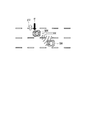
- FIG. 1 is a schematic configuration diagram of an apparatus according to the first embodiment of the present invention.
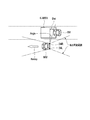
- FIG. 2 is a conceptual diagram illustrating an obstacle detection area and the like on the rear side.
- FIG. 3 is a diagram illustrating the configuration of the control unit.
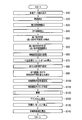
- FIG. 4 is a flowchart showing the processing procedure of the control unit in the first embodiment.
- FIG. 5 is a block diagram showing the concept of calculating the left overtaking accuracy amount.
- FIG. 6 is a block diagram showing the concept of calculating the lane change detection accuracy amount toward the left side obstacle.
- FIG. 7 is a conceptual diagram showing the relationship between the host vehicle and the obstacle.
- FIG. 8 is a diagram for explaining the operation in the first embodiment of the present invention.
- FIG. 1 is a schematic configuration diagram of an apparatus according to the first embodiment of the present invention.
- FIG. 2 is a conceptual diagram illustrating an obstacle detection area and the like on the rear side.
- FIG. 3 is a diagram illustrating the configuration of the control unit.
- FIG. 4
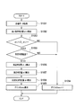
- FIG. 9 is a flowchart showing the processing procedure of the control unit in the second embodiment of the present invention.
- FIG. 10 is a flowchart showing the processing procedure of the control unit in the third and fourth embodiments of the present invention.
- FIG. 11 is a conceptual diagram for explaining a fourth embodiment of the present invention.
- FIG. 12 is a flowchart showing the processing procedure of the control unit in the fifth embodiment of the present invention.
- FIG. 13 is a flowchart showing the left gain calculation processing procedure.
- FIG. 14 is a diagram illustrating a merging point of the own vehicle travel lane.
- FIG. 15 is a diagram for explaining the operation in the fifth embodiment of the present invention.
- FIG. 1 is a schematic configuration diagram of an apparatus according to the first embodiment.
- FIG. 1 is a brake pedal.
- the brake pedal 1 is connected to the master cylinder 3 via the booster 2.
- reference numeral 4 in FIG. 1 denotes a reservoir.
- the master cylinder 3 is connected to each wheel cylinder 6FL, 6FR, 6RL, 6RR of each wheel 5FL, 5FR, 5RL, 5RR via the fluid pressure circuit 30.
- the brake fluid pressure is increased by the master cylinder 3 in accordance with the depression amount of the brake pedal 1 by the driver.
- the increased braking fluid pressure is supplied to the wheel cylinders 6FL, 6FR, 6RL, 6RR of the wheels 5FL, 5FR, 5RL, 5RR through the fluid pressure circuit 30.
- the braking fluid pressure control unit 7 controls the actuator 30A in the fluid pressure circuit 30 to individually control the braking fluid pressure to each wheel 5FL, 5FR, 5RL, 5RR. Then, the brake fluid pressure control unit 7 controls the brake fluid pressure to each of the wheels 5FL, 5FR, 5RL, and 5RR to a value corresponding to the command value from the braking / driving force control unit 8.
- the actuator 30A is provided corresponding to each of the wheel cylinders 6FL, 6FR, 6RL, 6RR, and is proportional to which the hydraulic pressure of each wheel cylinder 6FL, 6FR, 6RL, 6RR can be individually controlled to an arbitrary braking hydraulic pressure. There is a solenoid valve.
- the brake fluid pressure control unit 7 and the fluid pressure circuit 30 may use, for example, a brake fluid pressure control unit used in anti-skid control (ABS), traction control (TCS), or vehicle dynamics control device (VDC). Good.
- the brake fluid pressure control unit 7 may be configured to control the brake fluid pressure of each wheel cylinder 6FL, 6FR, 6RL, 6RR alone, that is, without using the fluid pressure circuit 30.
- the braking fluid pressure control unit 7 sets each braking fluid pressure according to the braking fluid pressure command value. Control.
- the vehicle also includes a drive torque control unit 12.
- the drive torque control unit 12 controls the drive torque to the rear wheels 5RL and 5RR that are drive wheels. This control is realized by controlling the operating state of the engine 9, the selected gear ratio of the automatic transmission 10, and the throttle opening of the throttle valve 11. That is, the drive torque control unit 12 controls the fuel injection amount and the ignition timing. At the same time, the throttle opening is controlled. Thereby, the operation state of the engine 9 is controlled.
- the drive torque control unit 12 outputs the value of the drive torque Tw, which is information at the time of control, to the braking / driving force control unit 8.
- the drive torque control unit 12 can control the drive torque Tw of the rear wheels 5RL and 5RR alone, that is, without using the braking / driving force control unit 8. However, when a driving torque command value is input from the braking / driving force control unit 8, the driving torque control unit 12 controls the driving torque Tw according to the driving torque command value.
- an imaging unit 13 with an image processing function is provided in the front part of the vehicle.
- the imaging unit 13 is used to detect the position of the host vehicle MM (see FIG. 2) in the travel lane.
- the imaging unit 13 is configured by a monocular camera including a CCD (Charge Coupled Device) camera, for example.
- the imaging unit 13 images the front of the host vehicle MM.
- the imaging unit 13 performs image processing on the captured image in front of the host vehicle MM, detects a lane marking such as a white line 200 (lane marker) (see FIG. 7), and travels based on the detected white line 200. Detect lanes.
- the imaging unit 13 determines an angle (yaw angle) ⁇ f between the travel lane of the host vehicle MM and the longitudinal axis of the host vehicle MM, a lateral displacement Xf with respect to the travel lane, and a travel lane. Is calculated.
- the imaging unit 13 outputs the calculated yaw angle ⁇ f, lateral displacement Xf, curvature lane curvature ⁇ , and the like to the braking / driving force control unit 8.
- the imaging unit 13 detects the white line 200 that forms the traveling lane, and calculates the yaw angle ⁇ f based on the detected white line 200. For this reason, the detection accuracy of the yaw angle ⁇ f is greatly influenced by the detection accuracy of the white line 200 of the imaging unit 13.
- curvature ⁇ of the traveling lane can be calculated based on a steering angle ⁇ of the steering wheel 21 described later.
- this vehicle is equipped with radar devices 24L / 24R.
- the radar devices 24L / 24R are sensors for detecting obstacles SM (FIG. 2) present in the left and right rear side directions, respectively. As shown in FIG. 2, the radar devices 24L / 24R can detect an obstacle SM on the side of the host vehicle MM. In the detectable range, an area that is a blind spot located at least on the rear side (of the driver) is set as an obstacle detection area K-AREA. If it exists, it is determined that the obstacle SM exists. In addition, the radar devices 24L / 24R can detect the relative lateral position POSXobst, the relative longitudinal position DISTobst, and the relative longitudinal velocity dDISTobs with respect to the obstacle SM, respectively.
- the extending direction of the host vehicle MM travel lane is the vertical direction
- the width direction of the host vehicle MM travel lane is the horizontal direction.
- the radar devices 24L / 24R are composed of, for example, millimeter wave radars.
- this vehicle is equipped with a radar device 23.
- the radar device 23 is a sensor for detecting an obstacle SM present in front of the host vehicle MM. This radar device 23 can detect the distance Dist_pre between the host vehicle MM and the front obstacle SM, and the relative speed Relvsp_pre between the host vehicle MM and the front obstacle SM.
- the vehicle also includes a master cylinder pressure sensor 17, an accelerator opening sensor 18, a steering angle sensor 19, a direction indicating switch 20, and wheel speed sensors 22FL, 22FR, 22LR, and 22RR.
- the master cylinder pressure sensor 17 detects the output pressure of the master cylinder 3, that is, the master cylinder hydraulic pressure Pm.
- the accelerator opening sensor 18 detects the depression amount of the accelerator pedal, that is, the accelerator opening ⁇ t (or the accelerator depression amount ⁇ t).
- the steering angle sensor 19 detects the steering angle (steering angle) ⁇ of the steering wheel 21.
- the direction indication switch 20 detects a direction indication operation by the direction indicator.
- the navigation system 40 is mounted on this vehicle.
- the navigation system 40 outputs to the braking / driving force control unit 8 route information set based on the driver's destination input together with road information such as map information including road curvature.
- FIG. 3 is a block diagram schematically showing the processing of the braking / driving force control unit 8.
- the processing of the braking / driving force control unit 8 is performed based on a flowchart shown in FIG. 4 to be described later. In FIG. 3, this processing is schematically shown as a block.
- the braking / driving force control unit 8 includes a future position estimation unit 8A, an obstacle approach prevention control unit 8B, a passing detection unit 8C, and a change intention detection unit 8D.
- the obstacle approach prevention control unit 8B includes a control suppression unit 8Ba.
- the future position estimation unit 8A is based on the driver's steering input detected by the steering input detection unit, and the vehicle's future position (the vehicle's future position in the travel lane width direction) after the forward gaze time Tt has elapsed.
- the vehicle predicted position ⁇ Xb) is predicted.
- the side obstacle detection unit 50 corresponds to the radar device 24L / 24R, and the presence / absence of the obstacle SM in the obstacle detection area K-AREA behind the own vehicle MM, and the relative lateral position of the obstacle SM with respect to the own vehicle MM.
- Information on the obstacle SM is detected based on the host vehicle MM, such as POSXobst, relative vertical position DISTobst, and relative vertical speed dDISTobst.
- the obstacle approach prevention control unit 8B performs obstacle approach prevention control that supports the approach prevention of the host vehicle MM with respect to the obstacle SM detected by the side obstacle detection unit 50. Specifically, when the side obstacle detection unit 50 determines that the obstacle SM behind the host vehicle MM is detected, the lateral position of the host vehicle future position 150 is the control start position 60 ( When reaching a predetermined lateral position in the lane width direction (see FIG. 7 described later), the control start of the obstacle approach prevention control is detected, and the obstacle approach prevention control is performed.
- the overtaking detection unit 8C is based on the information detected by the side obstacle detection unit 50, that is, the information on the obstacle SM based on the own vehicle MM, or the vehicle MM is overtaking the obstacle SM.
- the overtaking state which is at least one of the states predicted to be overtaken, is detected, and the detection information is output to the control suppression unit 8Ba.
- the change intention detection unit 8D calculates the driver's lane change intention accuracy. If the calculated lane change intention accuracy is high, the change intention detection unit 8D determines that the driver has a lane change intention and uses the information as a control suppression unit 8Ba. Output to.
- control suppression unit 8Ba determines the overtaking state based on the detection of the overtaking detection unit 8C, the control suppression unit 8Ba suppresses the obstacle approach prevention control compared to the case where the overtaking state is not determined.
- FIG. 4 is a flowchart showing an avoidance control processing procedure executed by the braking / driving force control unit 8.
- This avoidance control process is executed by timer interruption every predetermined sampling time ⁇ T (for example, every 10 msec).
- ⁇ T for example, every 10 msec.
- Vwfl and Vwfr are the wheel speeds of the left and right front wheels, respectively.
- Vwrl and Vwrr are the wheel speeds of the left and right rear wheels, respectively. That is, in the above equation (1), the vehicle speed V is calculated as an average value of the wheel speeds of the driven wheels.
- the vehicle speed V is calculated from the latter equation, that is, the wheel speeds Vwfl and Vwfr of the left and right front wheels 5FL and 5FR.
- ABS Anti-lock Brake System
- step S30 the braking / driving force control unit 8 detects the obstacle SM with respect to the obstacle detection area K-AREA set on the left and right rear sides of the host vehicle MM based on the signals from the left and right radar devices 24L / 24R.
- the presence / absence of existence Lobst / Robst is acquired.
- the relative position and relative speed of the rear side obstacle SM with respect to the host vehicle MM are also acquired.
- the rear side of the host vehicle MM refers to the side and the rear position of the host vehicle MM. That is, the rear side of the host vehicle MM includes an oblique rear position of the host vehicle MM.
- step S40 the braking / driving force control unit 8 reads from the imaging unit 13 the lateral displacement Xf of the host vehicle MM and the curvature ⁇ of the traveling lane in the currently traveling traveling path.
- the acquisition of the curvature ⁇ of the travel lane is not limited to the calculation based on the image captured by the imaging unit 13.
- the curvature information of the traveling lane at the vehicle position may be acquired.
- the yaw angle ⁇ f of the host vehicle MM with respect to the currently traveling road is calculated. This yaw angle ⁇ f is used to detect the running situation in the lane.
- the yaw angle ⁇ f is detected by, for example, converting an image in front of the vehicle imaged by the imaging unit 13 into an overhead image and detecting the angle of the white line 200 (lane marker) with respect to the vertical direction of the converted image. Can do.
- the yaw angle ⁇ f may be calculated based on the white line 200 in the vicinity of the host vehicle MM in the image captured by the imaging unit 13.
- the yaw angle ⁇ f is calculated by the following equation (2) using the change amount of the lateral displacement Xf of the host vehicle MM.
- the lateral displacement Xf is a position in the lane width direction in the traveling lane of the host vehicle MM with respect to the white line 200 (lane marker), and corresponds to the distance from the white line 200 to the host vehicle MM.
- dX is a change amount per unit time of the lateral displacement Xf
- dY is a change amount in the traveling direction per unit time
- dX ′ is a differential value of the change amount dX.
- the white line 200 detected in the vicinity may be extended far away, and the yaw angle ⁇ f may be calculated based on the extended white line 200.
- the calculation method of the lateral displacement Xf of the own vehicle MM, the curvature ⁇ of the traveling lane, the yaw angle ⁇ f, etc. based on these front images of the vehicle for example, recognizes the white line 200 such as a lane following traveling control device and controls the own vehicle MM. Since it is a well-known technique that has already been adopted for various devices, it will not be described in detail.
- Step S50 the overtaking state of the host vehicle MM with respect to the obstacle SM is detected.
- the detection of the overtaking state is information on the obstacle SM detected by the radar device 24L / 24R (side obstacle detection unit 50) (detected with reference to the own vehicle), the relative distance Dist, the relative speed Relvsp, and the detection angle. Detection is based on Angle information.
- the relative distance Dist, the relative speed Relvsp, and the detection angle Angle are in the relationship shown in FIG.
- the relative distance Dist is the relative distance of the obstacle SM with respect to the host vehicle MM, corresponds to the relative vertical position DISTobst, and is also referred to as a relative distance Dist below.
- the relative speed Relvsp is a relative speed of the host vehicle MM with respect to the obstacle SM, and can be calculated by differentiating the relative vertical position DISTobst, for example.
- the relative speed Relvsp is positive when the host vehicle MM is away from the side obstacle SM (when the host vehicle speed V in the traveling direction of the host vehicle MM is larger than the obstacle SM).
- the detection angle Angle is a detection angle of the obstacle SM with respect to the host vehicle MM, and is obtained from the relative horizontal position POSXobst and the relative vertical position DISTobst.
- This detection angle Angle is set to 0 degree when the obstacle SM is located directly beside the host vehicle MM. Then, the detection angle Angle becomes larger as the position of the obstacle SM with respect to the host vehicle MM is located behind the host vehicle MM with respect to the position directly next to the host vehicle MM, and the position of the obstacle SM is located immediately behind the host vehicle MM.
- the time when the object SM is located is set to 90 degrees.
- the position just beside the position may be the position beside the installation position of the radar devices 24L / 24R, or the position beside the vehicle center of gravity, for example.
- a determination threshold value KA1 of the detection angle Angle is set to 3 m, for example.
- the determination threshold value KR1 for the relative speed Relvsp is set at, for example, 2 to 3 m / s.
- the determination threshold KA1 for the detection angle Angle is set to 40 to 45 degrees, for example.
- the overtaking state refers to a state in which the own vehicle MM is predicted to be in a state where the lane can be changed to the obstacle SM side or a state where the lane can be changed after the own vehicle MM has overtaken the obstacle SM.
- the determination threshold values KD1, KR1, and KA1 are set based on experience values, experiments, or the like based on a state in which the host vehicle MM can change to the obstacle SM side or can be predicted to change to a lane.
- Step S55 If the detection that the possibility of overtaking is high is continued for a predetermined time for overtaking determination (when interrupt processing is continuously executed for a predetermined number of times), the process proceeds to step S55 to determine whether the overtaking state is present. Determine whether. The continuation determination can be performed based on the value of the counter using a counter that counts up each time processing is performed. Even if the state that is detected as being likely to be the overtaking state does not continue for the predetermined time for overtaking determination, the process proceeds to step S55 when the conditions (a) to (c) are satisfied, and the overtaking state is reached. It is good also as determination whether it is. In the first embodiment, in order to accurately determine that there is a high possibility of being in the overtaking state, it is determined whether the overtaking state has continued for a predetermined time for overtaking determination as described above.
- step S55 the left overtaking accuracy amount ⁇ L1 is calculated as shown in FIG. 5 based on the information on the left obstacle SM based on the host vehicle MM.
- KD (Dist) is a value calculated based on the map shown in the first overtaking accuracy amount calculation unit 501a of FIG. 5 using the relative distance Dist as a variable
- the relative distance Dist is a determination threshold value KD1 of the relative distance Dist. It becomes a predetermined value in the following cases, and KD (Dist) becomes smaller as the relative distance Dist becomes larger than the determination threshold KD1 of the relative distance Dist.
- the map shown in FIG. 5 may be stored in advance as a function, and the value of KD (Dist) may be obtained using the stored function.
- KR (Relvsp) is a value calculated based on the map shown in the second overtaking accuracy amount calculation unit 501b of FIG. 5 using the relative speed Relvsp as a variable, and the relative speed Relvsp is equal to or less than the determination threshold KR1 of the relative speed Relvsp. As the relative speed Relvsp becomes larger than the determination threshold value KR1, the value becomes smaller.
- the map shown in FIG. 5 may be stored in advance as a function, and the value of KR (Relvsp) may be obtained from the stored function.
- KA (Angle) is a value calculated based on the map shown in the third overtaking accuracy amount calculation unit 501c of FIG. 5 using the detection angle Angle as a variable, and the detection angle Angle is equal to or less than the determination threshold KA1 of the detection angle Angle.
- the detection angle Angle becomes smaller as the detection angle Angle becomes larger than the determination threshold value KA1.
- the map shown in FIG. 5 may be stored in advance as a function, and the value of KA (Angle) may be obtained from the stored function.
- the overtaking detection threshold is set to less than 1. This overtaking detection threshold value may be set from an experiment or an empirical value, although it differs depending on how much the accuracy of overtaking detection is set.
- FIG. 5 described above is a block diagram showing the concept of calculating the left overtaking accuracy amount ⁇ L1.
- a processing example of calculating the left overtaking accuracy amount ⁇ L1 will be described using this block diagram.
- the first overtaking accuracy amount calculation unit 501a calculates a first overtaking accuracy amount KD (Dist) based on the relative distance Dist with reference to the first overtaking accuracy amount calculation map.
- the vertical axis represents the first overtaking accuracy amount KD
- the horizontal axis represents the relative distance Dist.
- the second overtaking accuracy amount calculation unit 501b calculates a second overtaking accuracy amount KR (Relvsp) based on the relative speed Relvsp with reference to the second overtaking accuracy amount calculation map.
- the vertical axis represents the second overtaking accuracy amount KR
- the horizontal axis represents the relative speed Relvsp.
- the third overtaking accuracy amount calculation unit 501c calculates a third overtaking accuracy amount KA (Angle) with reference to the third overtaking accuracy amount calculation map based on the detection angle Angle of the rear side obstacle SM.
- the vertical axis represents the third overtaking accuracy amount KA
- the horizontal axis represents the detection angle Angle.
- a lower limit value (> 0) is provided for each of the first to third overtaking accuracy amounts KD, KR, and KA.
- the overtaking accuracy amount output unit 501d inputs the first to third overtaking accuracy amounts KD, KR, and KA, and outputs a final overtaking accuracy amount ⁇ L1.
- the passing accuracy amount ⁇ L1 is calculated by integrating the first to third passing accuracy amounts KD, KR, and KA, respectively.
- the overtaking state is detected, for example, based on whether or not the following expression is satisfied.
- D_ ⁇ L1 is a predetermined value (threshold value for overtaking detection) of 1 or less by experiment or the like. If the accuracy of overtaking state detection is set high, D_ ⁇ L1 may be set to a small value such as 0.5.
- ⁇ L1 is smaller than 1, one of the above (a) to (c) is satisfied. ⁇ L1 indicates that the smaller the value, the higher the accuracy of overtaking state detection.
- the right overtaking accuracy amount ⁇ R1 is also calculated by the same determination based on the information on the right obstacle SM of the host vehicle MM.
- step S55 when it is determined in step S50 that the possibility of the overtaking state is high, it is determined whether or not the overtaking state is based on the accuracy of the overtaking state. The overtaking state is judged.
- the overtaking accuracy amount ⁇ L1 ( ⁇ R1) indicating the detection accuracy of the overtaking state is equal to or less than a predetermined overtaking detection threshold ( ⁇ 1) (a state in which the overtaking state is detected) continues for a predetermined time.
- a flag F_Overtake indicating state determination is set to “1”. If the overtaking accuracy amount ⁇ L1 ( ⁇ R1) indicating the detection accuracy of the overtaking state is equal to or less than a predetermined overtaking detection threshold ( ⁇ 1) (when it is detected that the overtaking state is detected), the overtaking state is not waited for a predetermined time.
- a flag F_Overtake indicating the determination may be set to “1”.
- a flag F_Overtake indicating the overtaking state determination is set to “0”.
- the overtaking accuracy amount ⁇ L1 ( ⁇ R1) in step S55 is illustrated, but one of these three is used.
- the overtaking accuracy amount ⁇ L1 ( ⁇ R1) may be obtained from the obstacle information of 2.
- step S55 may be performed as follows.
- a determination flag F_ObstFront2Rear is provided.
- This determination flag F_ObstFront2Rear is set to “1” only when the obstacle SM moves out of the recognition range when the target obstacle SM changes from the front side to the side or rear side of the host vehicle MM. To "".
- the overtaking state is determined, and the flag F_Overtake indicating the overtaking state is set to 1. May be. Thereby, the overtaking state can be determined more accurately.
- the flag F_Overtake indicating the determination of the overtaking state is reset to “0” when ⁇ L1 ( ⁇ R1) exceeds the determination threshold of the overtaking state (when it is no longer in the detection state of the overtaking state).
- Hysteresis may be provided in a direction in which it is difficult to release the threshold of ⁇ L1 ( ⁇ R1) when the flag F_Overtake indicating the determination of the overtaking state is reset to “0”. That is, the release threshold value is set higher than the threshold value for determining the overtaking state.
- the flag F_Overtake indicating the overtaking state determination is set once, it may be set to “0” when the target object is not detected.
- the flag F_Overtake indicating the determination of the overtaking state is once set to “1” and then cleared (set to “0”) after being held for a predetermined time.
- the predetermined time for clearing the flag F_Overtake may be simply the time, or the time from when the overtaking state is detected until the travel distance of the host vehicle MM becomes a predetermined distance set in advance. Also good. That is, the flag F_Overtake may be cleared on the condition that the travel distance from the time when the overtaking state is detected is equal to or greater than a predetermined distance set in advance. In addition, for example, it may be a time until the relative distance between the host vehicle MM and the obstacle SM becomes equal to or greater than a predetermined distance, and the predetermined time is a value that can be appropriately changed.
- step S60 the presence or absence of the intention of the lane change operation (by the driver) toward the obstacle SM is detected.
- whether or not the driver intends to change the lane in the direction of the left obstacle SM is determined based on the steering angle operation / accelerator operation information operated by the driver. For example, as will be described later, in the direction of the left side obstacle SM based on the additional steering angle ⁇ , the steering angular speed D ⁇ , the accelerator depression amount ⁇ t (accelerator opening ⁇ t), and the direction switch signal (turn signal signal).
- the lane change detection accuracy amount ⁇ L2 (by the driver) is calculated.
- the additional steering angle ⁇ can be calculated from the steering angle ( ⁇ ) information from the steering angle sensor 19.
- the steering angular velocity D ⁇ can be calculated by differentiating the steering angle ( ⁇ ) information from the steering angle sensor 19.
- the accelerator depression amount ⁇ t can be calculated from accelerator opening ( ⁇ t) information from the accelerator opening sensor 18.
- the left lane change detection accuracy amount ⁇ L2 is calculated by the following equation.
- ⁇ L2 Kt (direction switch signal) ⁇ Ks ( ⁇ ) ⁇ KDs (D ⁇ ) ⁇ KAc ( ⁇ t)
- the processing for calculating the left lane change detection accuracy amount ⁇ L2 will be described with reference to FIG.
- FIG. 6 is a block diagram showing the concept of calculating the left lane change detection accuracy amount ⁇ L2.
- the first lane change detection accuracy amount calculation unit 601a calculates the first lane change detection accuracy amount Kt with reference to the first lane change detection accuracy amount calculation map based on the direction switch signal.
- the first lane change detection accuracy amount Kt 1, and the left lane change instruction direction.
- the second lane change detection accuracy amount calculation unit 601b calculates the second lane change detection accuracy amount Ks with reference to the second lane change detection accuracy amount calculation map based on the steering angle ⁇ .
- the second lane change detection accuracy amount calculation map takes the second lane change detection accuracy amount Ks on the vertical axis and the steering angle ⁇ on the horizontal axis.
- Ks 1, and in a region exceeding the steering angle determination threshold value ⁇ 1, the second lane change detection accuracy amount Ks decreases as the steering angle ⁇ increases.
- the third lane change detection accuracy amount calculation unit 601c calculates the third lane change detection accuracy amount KDs with reference to the third lane change detection accuracy amount calculation map based on the steering angular speed D ⁇ .
- the third lane change detection accuracy amount calculation map takes the third lane change detection accuracy amount KDs on the vertical axis and the steering angular velocity D ⁇ on the horizontal axis.
- KDs 1.
- the third lane change detection accuracy amount KDs is set to be smaller as the steering angular speed D ⁇ is larger. To do.
- the fourth lane change detection accuracy amount calculation unit 601d calculates the fourth lane change detection accuracy amount KAc with reference to the fourth lane change detection accuracy amount calculation map based on the accelerator depression amount ⁇ t.
- the fourth lane change detection accuracy amount calculation map takes the fourth lane change detection accuracy amount KAc on the vertical axis and the accelerator depression amount ⁇ t on the horizontal axis.
- KAc 1, and in a region exceeding the depression amount determination threshold ⁇ t1, the fourth lane change detection accuracy amount KAc decreases as the accelerator depression amount ⁇ t increases.
- a fifth lane change detection accuracy amount calculation unit is provided, and the fifth lane change detection accuracy amount is calculated based on the accelerator depression speed with reference to the fifth lane change detection accuracy amount calculation map.
- the amount may be calculated and used.
- the vertical axis represents the fifth lane change detection accuracy amount
- the horizontal axis represents the accelerator depression speed.
- the fifth lane change detection accuracy amount is set to “1” when the accelerator depression speed is equal to or lower than the depression speed determination threshold, and the fifth lane change detection accuracy amount increases as the accelerator depression speed increases in a region exceeding the depression speed determination threshold. Set to be smaller.
- the lane change detection accuracy amount output unit 601e inputs the first to fourth lane change detection accuracy amounts Kt, Ks, KDs, and KAc, and outputs a final lane change detection accuracy amount ⁇ L2.
- the lane change detection accuracy amount ⁇ L2 is calculated by integrating the first to fourth lane change detection accuracy amounts Kt, Ks, KDs, and KAc. That is, the lane change detection accuracy amount ⁇ L2 is calculated by the following equation.
- lane change detection accuracy amount ⁇ L2 Kt ⁇ Ks ⁇ KDs ⁇ KAc Note that the lane change detection accuracy amount ⁇ L2 may be calculated according to the steering angle increase amount from the time when it is determined as the overtaking state or the accelerator depression amount from the time when it is determined as the overtaking state.
- the difference in steering steering angle ⁇ is based on, for example, the steering angle str_filt_heavy obtained by applying a filter having a large time constant to the steering angle information and the steering angle str_filt_light applying a filter having a small time constant.
- the additional steering angle ⁇ obtained in this way is calculated as the additional steering angle taking into account the steering angular velocity.
- the accelerator depression amount is, for example, a difference between the information ⁇ t_filt_light filtered with a small time constant ( ⁇ t_filt_heavy- ⁇ t_filter_light) with respect to the information ⁇ t_filt_heavy filtered with a large time constant with respect to the accelerator opening information.
- the accelerator depression amount thus obtained is calculated as an accelerator depression amount that also takes into account the accelerator depression speed.
- the accelerator depression speed may be detected instead of the accelerator opening, and the presence or absence of the intention of the lane change operation may be detected based on the accelerator depression speed.
- these values are detected as instantaneous values, so that the maximum value of the detected values is held for a predetermined time (for example, 1 second).
- a lane change detection accuracy amount ⁇ R2 toward the right side obstacle is calculated.
- the final lane change detection accuracy amount ⁇ L2 ( ⁇ R2) is obtained from the product of the direction switch signal, the information on the steering angle ⁇ , the information on the steering angular velocity D ⁇ , the information on the accelerator depression amount ⁇ t, and the map value obtained from each.
- the lane change detection accuracy amount ⁇ L2 ( ⁇ R2) may be obtained by selecting these.
- the lane change detection accuracy amount ⁇ L2 may be calculated using one, two, or three of the first to fourth lane change detection accuracy amounts Kt, Ks, KDs, and KAc. That is, the lane change detection accuracy amount ⁇ L2 increases when the driver steers for the lane change or when the driver performs an accelerator operation or the like for the lane change ( ⁇ L2 Can be any value.
- the flag F_driverovertake_intention is set to “1”.
- the flag F_driverovertake_intention is set to “0” when the lane change detection accuracy amount ⁇ L2 ( ⁇ R2) exceeds the lane change predetermined determination threshold (preferably providing hysteresis).
- step S60 may be omitted.
- step S70 the braking / driving force control unit 8 calculates a neutral yaw rate ⁇ ′ path based on the following equation (3).
- the neutral yaw rate ⁇ ′ path is a yaw rate necessary for the host vehicle MM to maintain traveling along the traveling path.
- the neutral yaw rate ⁇ ' path is zero while driving on a straight road.
- the neutral yaw rate ⁇ ′ path changes depending on the curvature ⁇ . Therefore, the curvature ⁇ of the travel lane is used when calculating the neutral yaw rate ⁇ ′ path .
- the neutral yaw rate ⁇ to maintain the travel path 'path is neutral yaw rate ⁇ predetermined period' or over path 'neutral yaw rate ⁇ or, or a large filter time constant using a ave' average ⁇ of path
- the calculated value may be simply calculated.
- step S80 the braking / driving force control unit 8 sets a forward gaze time Tt.
- the forward gaze time Tt is a predetermined time for determining a threshold for predicting a situation in which the driver will approach the obstacle SM in the future. For example, the forward gaze time Tt is set to 1 second.
- the target yaw rate ⁇ driver is calculated from the steering angle ⁇ and the vehicle speed V as in the following equation.
- This target yaw rate ⁇ driver is a yaw rate that the driver is trying to generate by a steering operation. That is, it means the yaw rate that the driver intends to generate.
- Kv Kv ⁇ ⁇ ⁇ V (4)
- Kv is a gain determined in advance according to vehicle specifications.
- the corrected target yaw rate ⁇ drivercorrection is calculated by the following equation.
- the corrected target yaw rate [psi Drivercorrection from the target yaw rate [psi driver, is a value obtained by subtracting the neutral yaw rate phi 'path needed to travel the traveling path. As a result, the influence of steering performed for traveling on a curved road from the target yaw rate ⁇ driver is eliminated.
- the corrected target yaw rate ⁇ drive correction is a deviation between the yaw rate (neutral yaw rate ⁇ ′ path ) necessary for traveling along the traveling lane and the yaw rate (target yaw rate ⁇ driver ) that the driver is trying to generate by the steering operation. And the yaw rate according to the driver's intention to change lanes.
- step S90 the braking / driving force control unit 8 uses the forward gaze time Tt set in step S80, and based on the following equation (6), the lateral position (traveling road width) of the current host vehicle MM.
- the lateral position of the host vehicle MM after the forward gazing time Tt that is, the predicted position ⁇ Xb of the host vehicle is calculated. That is, the lateral distance from the current lateral position of the host vehicle MM to the lateral position 150 of the host vehicle MM after the forward gazing time Tt is calculated as the predicted host vehicle position ⁇ Xb.
- the host vehicle predicted position ⁇ Xb is used to determine whether to start avoidance control for the obstacle SM, as will be described later.
- ⁇ Xb (K 1 ⁇ ⁇ f + K 2 ⁇ ⁇ m + K 3 ⁇ ⁇ m ′) (6) here, ⁇ f: Yaw angle, ⁇ m: target yaw angular velocity, ⁇ m ′: Target yaw angular acceleration.
- the target yaw angular velocity ⁇ m is given by the following formula.
- ⁇ m ⁇ drivercorrection ⁇ Tt (7)
- the target yaw angular acceleration ⁇ m ′ is expressed by the following equation.
- ⁇ Xb L ⁇ (K1 ⁇ f + K2 ⁇ m ⁇ Tt + K3 ⁇ m ′ ⁇ Tt 2 ) (9)
- the front gaze distance L and the front gaze time Tt are in the relationship of the following formula.
- the set gain K1 is a value obtained by using the vehicle speed V as a function.
- the set gain K2 is a value that is a function of the vehicle speed V and the forward gaze time Tt.
- the setting gain K3 is a value that is a function of the square of the vehicle speed V and the forward gaze time Tt.
- the predicted position of the host vehicle MM may be calculated by selecting the steering angle component and the steering speed component individually and performing a select high, as in the following equation.
- step S100 the braking / driving force control unit 8 sets a determination threshold value for starting control.
- This determination threshold value is a determination threshold value for determining whether to start avoidance control for the rear side obstacle SM.
- the avoidance control start determination in step S100 is based on the lateral position of the host vehicle MM after the forward gaze time Tt and the lateral position of the obstacle SM. It is determined whether or not there is a possibility of intrusion, and even if it is determined that the avoidance control is started in step S100, the avoidance control is not necessarily actually started. Whether or not the avoidance control is actually started is determined in step S115 described later.
- ⁇ O shown in FIG. 7 is set as the determination threshold, and the start of avoidance control is determined based on the determination threshold ⁇ O and the predicted vehicle position ⁇ Xb.
- ⁇ O is a lateral relative distance between the host vehicle MM and the obstacle SM detected by the radar devices 24L / 24R.
- the determination threshold is set using the obstacle distance X2obst which is a predetermined distance.
- the obstacle distance X2obst corresponds to a lateral distance from the virtual predetermined position (lane width direction position) where the obstacle SM exists to the white line 200.
- the obstacle distance X2obst is 0 when the lane width direction virtual predetermined position where the obstacle SM exists is the white line 200 position, and is positive when the white line 200 is outside, and when it is inside the white line 200. Negative value. That is, the determination threshold is set with the value obtained by adding the lateral displacement X0 of the host vehicle MM and the obstacle distance X2obst in FIG. 7 as the virtual distance from the host vehicle MM to the obstacle SM. Note that the lateral displacement X0 in FIG. 7 corresponds to the lateral displacement Xf detected by the imaging unit 13 described above.
- a predetermined threshold value Xthresh may be set as the determination threshold value.
- the predetermined threshold value Xthresh is a preset value indicating how far the host vehicle future position (host vehicle predicted position ⁇ Xb) is from the current position of the host vehicle.
- the driver is performing an extremely large steering operation, and the host vehicle MM may enter the path of the obstacle SM after the forward gaze time Tt. It is a value that can be determined to have. Accordingly, the predetermined threshold value Xthresh is set to a large value that can reliably detect that the driver of the host vehicle MM has a lane change intention.
- an XY coordinate system is used in which the Y axis is taken in the direction along the road and the X axis is taken in the direction perpendicular to the road, that is, in the lane width direction. Then, the lateral position of the obstacle SM is detected on the X-axis coordinates. Based on the lateral position, the lateral relative distance ⁇ O is obtained.
- the obstacle detection area K-AREA for detecting the obstacle SM or setting it as an area is set to have a predetermined vertical and horizontal position on the rear side of the host vehicle MM.
- the vertical position may be set such that the obstacle detection area K-AREA increases as the relative speed Relvsp at which the obstacle SM approaches the host vehicle MM increases.
- step S110 the braking / driving force control unit 8 determines whether or not the host vehicle MM is approaching the rear side obstacle SM.
- This control start determination is performed by setting an obstacle approach prevention control determination flag Fout_obst based on the positional relationship between the host vehicle MM and the obstacle SM, and whether or not the control is actually started will be described later. To be determined based on the determination result in step S115.
- step S110 it is determined that the control is started when the following expression is satisfied (start condition 1).
- the own vehicle predicted position ⁇ Xb with respect to the lateral relative distance ⁇ O is the degree of approach to the obstacle SM. That is, this sets the position of the obstacle SM in the lane width direction as the control start determination position (control start position 60), and the future position of the host vehicle after the front gaze time Tt (front gazing point 150) is the control start position. This is synonymous with determining that control is started when the vehicle is outside the lane width direction from 60.
- a position on the inner side in the lane width direction by a predetermined distance from the position of the obstacle SM may be used as a control start determination position (control start position 60). In that case, a predetermined distance may be subtracted from the lateral relative distance ⁇ O to correct the lateral relative distance ⁇ O.
- ⁇ X2 ⁇ Xb ⁇ X0 ⁇ X2obst (13) That is, as shown in FIG. 7, it is determined whether or not the lateral distance ⁇ X2 between the white line 200 and the future predicted position (front gazing point 150) of the host vehicle MM after the forward gazing time Tt is greater than or equal to the obstacle distance X2obst. judge. That is, it is determined whether or not the lateral position of the host vehicle MM after the forward gazing time Tt (front gazing point 150) is outside the lane width direction with respect to the white line 200 with respect to the predetermined position of the obstacle distance X2obst.
- the radar device 24L / 24R detects the presence of the obstacle SM in the obstacle detection area K-AREA and satisfies the start condition 2, it determines that the control for the obstacle SM is started.
- the obstacle approach prevention control determination flag Fout_obst is set to ON.
- the obstacle approach prevention control determination flag Fout_obst is set to OFF.
- a predetermined threshold value Xthresh as a determination threshold value for starting control.
- the radar device 24L / 24R detects the presence of the obstacle SM in the obstacle detection area K-AREA, and determines that the control is started when the following expression is satisfied (start condition 3).
- the obstacle SM to be controlled may include not only a vehicle in the rear direction of the host vehicle MM but also an oncoming vehicle in front of the adjacent lane.
- a hysteresis of F may be provided as ⁇ X2 ⁇ O ⁇ F. That is, a dead zone may be set. That is, a dead zone may be provided between the control intervention threshold and the control end threshold.
- the control execution direction Dout_obst is determined based on the determination direction of the future predicted position (the forward gaze point 150).
- the future predicted position front gazing point 150
- Dout_obst LEFT
- Dout_obst RIGHT
- the obstacle approach prevention control determination flag Fout_obst is set to OFF. This is to prevent the obstacle approach prevention control from being activated during the operation of automatic braking control, which is control performed regardless of the driver's steering.
- step S115 it is determined whether to execute the obstacle approach prevention control based on the obstacle approach prevention control judgment flag Fout_obst and the flag F_Overtake indicating the overtaking state judgment.
- the obstacle approach prevention control determination flag Fout_obst is OFF, the obstacle approach prevention control determination flag Fout_obst is maintained OFF regardless of F_Overtake.
- the obstacle access prevention control may not be executed based only on the state of F_Overtake by setting the obstacle access prevention control determination flag Fout_obst to OFF.
- step S120 a process of notifying the driver is performed. That is, if the obstacle approaching prevention control determination flag Fout_obst is determined to be ON, an alarm sound is generated.
- the notification is not limited to the alarm sound, and may be performed by vibration of a lamp or a seat.
- the notification may be performed at an earlier timing than the front gaze point 150 (the lateral position of the host vehicle MM after the front gaze time Tt) based on the above-mentioned front gaze time Tt reaches the control start position.
- the predetermined gain Kbuzz > 1 is applied so as to be longer than the forward gaze time Tt.
- an alarm may be generated when it is determined that the forward gazing point 150 calculated based on the above equation (6) has reached the determination threshold.
- an alarm may be generated when it is determined that the obstacle approach prevention control operation is started, and the control may be started after a predetermined time has elapsed. Or you may make it generate
- step S130 the braking / driving force control unit 8 sets a target yaw moment Ms.
- step S140 When the obstacle approaching prevention control determination flag Fout_obst is OFF, the target yaw moment Ms is set to 0, and the process proceeds to step S140.
- the target yaw moment Ms is calculated by the following equation, and the process proceeds to step S140.
- K1recv is a proportional gain determined from vehicle specifications (yaw inertia moment).
- K2recv is a gain that varies according to the vehicle speed V.
- the gain K2recv is set to be a large value in a low speed range, an inversely proportional relationship with the vehicle speed V when the vehicle speed V reaches a certain value, and a constant value with a small value when the vehicle speed V is reached thereafter.
- the set gain K1mon is a value that is a function of the vehicle speed.
- the set gain K2mon is a value that is a function of the vehicle speed and the forward gaze time Tt.
- the target yaw moment Ms increases as the yaw rate steadily generated by the yaw angle ⁇ f with respect to the white line 200 and the steering wheel increased by the driver increases.
- the target yaw moment Ms may be calculated from the following equation (19).
- the set gain K3 is a gain that decreases as the forward gaze time Tt increases.
- the host vehicle MM includes a lane departure prevention control for controlling the vehicle behavior of the host vehicle MM so as to prevent the lane departure when there is a possibility of departure from the lane.
- step S140 the braking / driving force control unit 8 calculates a command for generating the target yaw moment Ms for avoiding the obstacle SM, outputs the command, and then returns to the first process.
- the Ka is a coefficient obtained in advance by experiments or the like for converting the yaw moment into the steering reaction force.
- the Kb is a coefficient obtained in advance by experiments or the like for converting the yaw moment into the steering angle.
- the braking / driving force control unit 8 when the braking force difference between the left and right wheels of the vehicle is generated as means for generating the yaw moment, the braking / driving force control unit 8 generates the target yaw moment Ms as described below. Calculate the command.
- the brake fluid pressures (brake fluid pressures) Pmf and Pmr are set as shown in the following equations (20) and (21), respectively.
- Pmf is the brake fluid pressure for the front wheels.
- Pmr is the braking fluid pressure for the rear wheels, and is a value calculated based on the braking fluid pressure Pmf for the front wheels in consideration of the front-rear distribution. For example, if the driver is operating a brake, the brake fluid pressures Pmf and Pmr are values corresponding to the operation amount of the brake operation (master cylinder fluid pressure Pm).
- the front wheel target braking hydraulic pressure difference ⁇ Psf and the rear wheel target braking hydraulic pressure difference ⁇ Psr are calculated based on the target yaw moment Ms. Specifically, the target braking hydraulic pressure differences ⁇ Psf and ⁇ Psr are calculated by the following equations (22) and (23).
- FRratio is a threshold value for setting
- Tr is a tread
- Kbf and Kbr are conversion coefficients for the front wheels and the rear wheels when the braking force is converted into the braking hydraulic pressure.
- tread Tr is treated as the same value before and after here for convenience.
- Kbf and Kbr are coefficients determined in advance by brake specifications.
- the braking force of the wheel on the obstacle SM avoidance side (the side opposite to the direction in which the obstacle SM exists) is the obstacle SM side (the obstacle SM exists).
- the braking / driving force difference between the left and right wheels is generated so as to be larger than the braking force of the wheels on the left side.
- step S55 the flag F_Overtake indicating the overtaking state determination is “0” (step S55).
- the host vehicle predicted position ⁇ Xb is calculated as the host vehicle future position after the forward gaze time Tt (Ste S90).
- Tt ⁇ Kbuzz warning forward gaze time
- the driving support control for avoiding the obstacle SM is started. Is determined (step S110).
- a target yaw moment Ms is calculated as a control amount based on the own vehicle predicted position ⁇ Xb (step S130). Then, the braking / driving force (braking fluid pressure) is controlled so that the calculated target yaw moment Ms is generated (step S140). As a result, the vehicle behavior of the host vehicle MM is controlled in a direction to prevent the approach to the obstacle SM (perform obstacle access prevention control).
- step S50 in order to determine that the host vehicle MM is overtaking the obstacle SM, the left overtaking accuracy amount ⁇ L1 ⁇ 1 (step S50). Further, the flag F_Overtake indicating the overtaking state determination based on the left overtaking accuracy amount ⁇ L1 is “1” (step S55).
- the calculation is performed using the control front gaze time Tt.
- the predicted vehicle position ⁇ Xb is determined to be equal to or greater than ⁇ O and the obstacle approach prevention control is started.
- the start of the obstacle approach prevention control for preventing the approach to the obstacle SM is controlled. In one embodiment, the obstacle approach prevention control is not performed.
- the obstacle approach prevention control is not performed. That is, when it is detected that the host vehicle MM is overtaking the obstacle SM, the start of the obstacle approach prevention control is suppressed as compared with the case where the overtaking state is not detected. When the obstacle SM is overtaken, it is considered that the driver recognizes the obstacle SM. Therefore, in such a case, by suppressing the start of the control, when the driver changes the lane in the direction in which the obstacle SM exists while recognizing the obstacle SM, the obstacle approach prevention control is performed. It is possible to reduce the driver's uncomfortable feeling due to the fact that the vehicle MM operates sufficiently and is controlled in a direction away from the obstacle SM.
- the left lane change detection accuracy amount ⁇ L2 is calculated as detection of the lane change intention (step S60). Then, only when it is detected that there is a lane intention based on the left lane change detection accuracy amount ⁇ L2, processing is performed so that the flag F_Overtake indicating determination of the overtaking state becomes “1”.
- the start of the control is suppressed only when it is detected that the driver intentionally changes the lane. For this reason, the uncomfortable feeling given to the driver can be mitigated more accurately.
- the radar devices 24L / 24R constitute the side obstacle detection unit 50.
- Steps S100, S110, S120, S130, and S140 constitute the obstacle approach prevention control unit 8B.
- Steps S50 and S55 constitute an overtaking detection unit 8C.
- Step S60 constitutes the change intention detection unit 8D.
- Step S115 constitutes the control suppression unit 8Ba.
- the side obstacle detection unit 50 uses at least the rear side of the host vehicle MM as an obstacle detection area K-AREA, and detects an obstacle SM present in the obstacle detection area K-AREA.
- the obstacle approach prevention control unit 8B performs obstacle approach prevention control for preventing the host vehicle MM from approaching the obstacle SM detected by the side obstacle detection unit 50.
- the overtaking detection unit 8C is based on the information on the obstacle SM based on the own vehicle MM, and is in at least one of the states where the own vehicle MM is overtaking the obstacle SM or predicted to be overtaken The overtaking state is detected.
- the control suppression unit 8Ba determines the overtaking state based on the detection of the overtaking detection unit 8C, the control suppression unit 8Ba suppresses the start of the obstacle approach prevention control as compared to the case where the overtaking state is not determined.
- the host vehicle MM approaches the obstacle SM and satisfies the start condition of the obstacle approach prevention control in a situation where it can be determined that the host vehicle MM overtakes the obstacle SM or is predicted to be in a state of overtaking the obstacle SM.
- the driver of the host vehicle MM intends to change the lane to the obstacle SM side while recognizing the presence of the obstacle SM.
- the change intention detection unit 8D detects whether or not the driver intends to change lanes.
- the control suppression unit 8Ba suppresses the start of the obstacle approach prevention control when it is determined as the overtaking state based on the detection of the overtaking detection unit 8C and the lane change intention is detected by the change intention detection unit 8D.
- the driver's uncomfortable feeling can be suppressed by suppressing the start of the obstacle approach prevention control.
- the start of the obstacle approach prevention control is suppressed only when it is detected that the driver intentionally changes the lane.
- the start of control is suppressed, so that a sense of incongruity can be more reliably prevented.
- the information of the obstacle SM based on the host vehicle MM is at least one of the relative distance Dist of the obstacle SM with respect to the host vehicle MM, the relative speed Relvsp, and the detection angle Angle of the obstacle SM with respect to the host vehicle MM. More than one.
- a generally vehicle-mountable device such as the radar device 24L / 24R without using a special device such as inter-vehicle communication or infrastructure.
- the obstacle approach prevention control by the obstacle approach prevention control unit 8B generates a yaw moment in a direction away from the obstacle SM in the own vehicle MM or notifies the approach of the own vehicle MM to the obstacle SM. At least one of the processes is performed.
- the overtaking state is determined after the predetermined time has elapsed based on the vehicle speed.
- the relative distance Dist between the host vehicle MM and the obstacle SM becomes a predetermined distance (when the time necessary for the relative distance Dist to become the predetermined distance has elapsed).
- control start is suppressed when it is determined that the vehicle is overtaking and when it is detected that there is a lane change intention (that the lane change intention accuracy is high). Control start may be suppressed only by determining the overtaking state.
- the change intention detection part 8D demonstrated the case where the presence or absence of the lane change intention was detected based on a driver
- the change intention detection unit 8D detects the presence or absence of a lane change intention based on the behavior of the host vehicle MM.
- the change intention detection unit 8D may detect whether or not there is a lane change intention based on a change in yaw moment or a change in acceleration generated in the host vehicle MM by the driver's steering.
- a change in yaw moment or a change in acceleration can be detected by, for example, a differential value of yaw moment or a differential value of acceleration.
- the change intention detection unit 8D may detect the presence or absence of a lane change intention based on the relative movement of the host vehicle MM with respect to the white line 200 (lane marking line).
- the relative movement of the host vehicle MM with respect to the white line 200 is detected by, for example, the magnitude of the lateral speed and the magnitude of the yaw angle ⁇ f.
- the change intention detection unit 8D may detect the presence or absence of a lane change intention based on the relative speed in the lateral direction of the host vehicle MM with respect to the obstacle SM.
- the determination threshold value KD1 of the relative distance Dist when determining that the overtaking state is detected by the overtaking detection unit 8C may be smaller when the relative speed Relvsp is large than when the relative speed Relvsp is small.
- the determination threshold value KD1 of the relative distance Dist when the overtaking detection unit 8C determines that the overtaking state is present is such that the detection angle Angle of the obstacle SM is an angle on the side of the rear side of the own vehicle with reference to the side position of the own vehicle. The smaller the value, the better.
- the detection angle Angle is behind the side direction of the host vehicle, for example, when the positional relationship is such that the obstacle SM is reflected in the driver's room mirror, it is determined that the vehicle has overtaken even if the relative distance Dist is small. it can. As a result, it is possible to suppress the start of control with an uncomfortable feeling that does not match the driver's feeling.
- the second embodiment is an embodiment in which the start of control is suppressed by making it difficult to enter control by changing the control start condition.
- the lane change detection accuracy amount ⁇ L2 ( ⁇ R2) becomes smaller as the lane change intention accuracy (certainty) is higher (certain) as described above.
- the lane change intention accuracy is the accuracy of the intention of the driver to change the lane, but a value obtained by multiplying the lane change detection accuracy amount ⁇ L2 ( ⁇ R2) by the overtaking detection accuracy amount ⁇ L1 ( ⁇ R1) indicating overtaking ( For example, ⁇ L2 ⁇ ⁇ L2 ⁇ ⁇ L1) may be used as the overall lane change intention accuracy.
- FIG. 9 is a flowchart showing an avoidance control processing procedure executed by the braking / driving force control unit 8 in the second embodiment.
- step S85 is added instead of omitting step S115 in FIG. 4, as shown in FIG.
- Other configurations and processes are the same as those in the first embodiment.
- Step S80 As in the first embodiment, a forward gaze time Tt for determining a threshold for predicting a situation in which the driver will approach the obstacle SM in the future is set.
- step S85 when the flag F_Overtake indicating the overtaking state determination is “1”, the forward gaze time Tt is reset by the following equation. As a result of resetting the forward gaze time Tt to a short value by this resetting, the front gaze point 150 is shortened. On the other hand, when the flag F_Overtake is “0”, the process proceeds to step S90.
- Tt Tt ⁇ ⁇ L2 (for left obstacle SM)
- Tt Tt ⁇ ⁇ R2 (for right obstacle SM)
- Other configurations and processes are the same as those in the first embodiment.
- the start of the obstacle approach prevention control is suppressed as compared with the case where the vehicle MM is not determined to be the overtaking state.
- the obstacle approach prevention control is sufficiently operated and the driving caused by the own vehicle MM being controlled in the direction away from the side obstacle SM. It is possible to reduce a person's uncomfortable feeling.
- the control start suppression amount is increased (the forward gazing time Tt is set to a shorter value), so that the driver can feel less discomfort and perform driving support control.
- steps S60 and S85 constitute a change intention accuracy determination unit 8Da.
- the forward gaze time Tt constitutes a predetermined time.
- the change intention accuracy determination unit 8Da determines the lane change intention accuracy detected by the change intention detection unit 8D.
- the control suppression unit 8Ba starts with the control suppression unit 8Ba when the lane change intention accuracy determined by the change intention accuracy determination unit 8Da (steps S60 and S85) is higher than when the lane change intention accuracy is low. Strengthen the suppression.
- the lane change intention accuracy is determined based on the state of the direction indicator.
- Detecting accuracy of lane change intention is detected by the direction indicator, that is, direction switch signal. For this reason, it is possible to detect early that the driver has a strong intention to overtake and change lanes by explicitly indicating a turn signal (high lane change intention accuracy). As a result, the start of control with a sense of incongruity can be suppressed.
- the lane change intention accuracy is determined based on the steering angle ⁇ or the steering speed D ⁇ .
- the lane change intention accuracy is detected based on the vehicle acceleration state, which is known from the driver's accelerator operation or the like.
- the obstacle approach prevention control unit 8B determines the start of the obstacle approach prevention control based on the host vehicle future position (host vehicle predicted position ⁇ Xb) predicted after a predetermined time (forward gaze time Tt).
- the control suppression unit 8Ba suppresses the start of the obstacle approach prevention control by shortening the predetermined time (forward gaze time Tt).
- This third embodiment is also an embodiment in which the start of control is suppressed by making it difficult to enter control by changing the control start condition.
- the forward gaze time Tt is reset to be shorter during determination as the overtaking state in step S85.
- the control start is suppressed by resetting the control start determination threshold value on the obstacle SM side.
- FIG. 10 is a flowchart showing an avoidance control processing procedure executed by the braking / driving force control unit 8 in the third embodiment.
- step S105 is added instead of deleting step S115 in FIG.
- Step S105 when the flag F_Overtake indicating the overtaking state determination is “1”, the determination threshold value for starting the control is reset on the obstacle SM side. On the other hand, when the flag F_Overtake is “0”, the process proceeds to step S110.
- step S110 of the first embodiment when the start condition 1 is used, that is, when the condition of “ ⁇ Xb ⁇ ⁇ O (12)” is used as the start condition, the control start is started.
- the determination threshold for this is ⁇ O.
- the determination threshold is reset by performing the following process.
- the ⁇ X correction is set so that the smaller the lane change detection accuracy amount ⁇ L2 ( ⁇ R2), the larger the value. Note that ⁇ X correction may be a constant value.
- the control forward gaze time Tt is used. It is determined whether or not the calculated predicted vehicle position ⁇ Xb is greater than or equal to ⁇ O. If ⁇ Xb is greater than or equal to ⁇ O, it is determined that control is to be started. At this time, in the third embodiment, since ⁇ O is increased, that is, the determination threshold value for starting control is reset on the obstacle SM side in the lane width direction, control start is suppressed. . That is, as compared with the case where it is determined that the vehicle is not overtaken, the control is started when the vehicle approaches the obstacle SM, so that the control is difficult to start.
- the start of the obstacle approach prevention control is suppressed as compared with the case where the vehicle MM is not determined to be the overtaking state.
- the obstacle approach prevention control is sufficiently operated and the driving caused by the own vehicle MM being controlled in the direction away from the side obstacle SM. It is possible to reduce a person's uncomfortable feeling.
- the control start suppression amount is increased, so that the driving assistance control can be performed while further reducing the uncomfortable feeling given to the driver.
- step S105 constitutes a change intention accuracy determination unit 8Da.
- the obstacle approach prevention control unit 8B determines the start of the obstacle approach prevention control based on the control start position 60 set for the obstacle SM or the white line 200.
- the control suppression unit 8Ba suppresses the start of the obstacle approach prevention control by changing the setting of the control start position 60 to the obstacle SM side.
- the control start is suppressed by setting the control start threshold with respect to the white line 200 to the back (obstacle SM side). Thereby, the control operation can be performed when approaching a distance close to the obstacle SM while suppressing the start of unnecessary control.
- the fourth embodiment is also an embodiment in which the start of control is suppressed by making it difficult to enter control by changing the control start condition.
- the forward gaze time Tt is reset to be shorter during determination as the overtaking state in step S85.
- the control start is suppressed by temporarily changing the obstacle detection area K-AREA.
- FIG. 10 A flowchart showing an avoidance control processing procedure executed by the braking / driving force control unit 8 in the fourth embodiment is shown in FIG. 10 as in the third embodiment.
- step S105 of the third embodiment is different between step S105 of the fourth embodiment.
- the process will be described.
- FIG. 11 shows an example of the changed state.
- step S110 if it is determined that it does not exist, the process ends and returns.
- the start of the obstacle approach prevention control is suppressed as compared with the case where the vehicle MM is not determined to be the overtaking state.
- the obstacle approach prevention control is sufficiently operated and the driving caused by the own vehicle MM being controlled in the direction away from the side obstacle SM. It is possible to reduce a person's uncomfortable feeling.
- the control start suppression amount is increased, so that it is possible to perform the driving support control while further reducing the uncomfortable feeling given to the driver.
- step S105 constitutes a change intention accuracy determination unit 8Da.
- the control suppression unit 8Ba suppresses the start of the obstacle approach prevention control by reducing the obstacle detection area K-AREA.
- the obstacle access prevention control start is suppressed by reducing the obstacle detection area K-AREA for detecting the obstacle SM as a control target. This makes it possible to activate the control when approaching a distance close to the obstacle SM while suppressing the start of unnecessary control.
- the imaging unit 13 of the fifth embodiment also detects a merging situation in front and side of the host vehicle MM travel lane. Specifically, the distance Dist_lane from the host vehicle MM to the junction 300 is detected based on the captured image in front of the host vehicle MM.
- the imaging unit 13 in the fifth embodiment calculates the yaw angle ⁇ f, the lateral displacement Xf, and the curvature ⁇ of the travel lane as well as the first embodiment, and based on the image ahead of the host vehicle MM.
- the distance Dist_lane from the host vehicle MM to the junction 300 where the host lane joins the adjacent lane Is detected is detected.
- the traveling lane of the host vehicle MM joins the adjacent lane based on the image ahead of the host vehicle MM. Since it is a well-known technique, description is abbreviate
- the traveling lane of the host vehicle MM joins the adjacent lane and the distance Dist_lane to the junction 300 is detected. It is not limited to this.
- the merge point 300 is detected from the map information of the navigation device, and the merge point 300 is detected based on the detected merge point 300 and the position of the own vehicle 300 detected using the global positioning system (GPS).
- GPS global positioning system
- the distance Dist_lane may be detected.
- FIG. 12 is a flowchart for explaining the processing of the fifth embodiment.
- the process of step S115 in the flowchart of the first embodiment described above (see FIG. 4) is omitted and step S125 is added. Since other processes are the same as those in the first embodiment, the description thereof will be omitted below.
- step S125 the braking / driving force control unit 8 calculates a gain K3recv ( ⁇ 1), which will be described later, in accordance with the state in which the host vehicle MM has passed the side obstacle SM.
- the gain K3recv becomes a smaller value as it is determined that the host vehicle MM is passing the side obstacle SM (the higher the accuracy of the passing state is).
- FIG. 13 is a flowchart showing the procedure for calculating the gain K3recv performed in step S125.
- step S1051 the braking / driving force control unit 8 acquires various data and proceeds to step S1052.
- step S1051 each wheel detected by the wheel speed sensors 22FL, 22FR, 22LR, 22RR, the steering angle sensor 19, the accelerator opening sensor 18, and the master cylinder pressure sensor 17 is detected as in step S10 of FIG.
- the information of the front obstacle SM is the distance Dist_pre between the host vehicle MM and the front obstacle SM and the relative speed Relvsp_pre between the host vehicle MM and the front obstacle SM detected by the radar device 23.
- the joining state of the own vehicle traveling lane is a distance Dist_lane from the own vehicle MM to the joining point 300 in front of the vehicle.
- step S1052 the overtaking accuracy amount ⁇ L1 is calculated by the same processing as in step S55 in the flowchart of FIG.
- step S1053 the braking / driving force control unit 8 determines whether the overtaking accuracy amount ⁇ L1 calculated in step S1052 is smaller than the overtaking detection threshold “D_ ⁇ L1 ( ⁇ 1)”. Determine whether or not.
- step S1055 On the other hand, if ⁇ L1 ⁇ D_ ⁇ L1 is determined in step S1053, it is determined that the overtaking state is established, and the process proceeds to step S1055. It is determined whether or not a predetermined time has elapsed.
- step S1054 If the predetermined time has elapsed, the process proceeds to step S1054. If the predetermined time has not elapsed, the process proceeds to step S1056.
- step S1056 the braking / driving force control unit 8 performs the left lane change detection accuracy amount ⁇ L2 by the same processing as in step S60 in the flowchart of FIG. 4 based on the driving operation performed by the driver acquired in step S1051. Is calculated.
- step S1057 the braking / driving force control unit 8 calculates the approach determination amount ⁇ 3 to the front obstacle SM based on the information on the front obstacle SM acquired in step S1051.
- the distance Dist_pre between the host vehicle MM and the front obstacle SM As the information of the front obstacle SM, the distance Dist_pre between the host vehicle MM and the front obstacle SM, and the relative speed Relvsp_pre between the host vehicle MM and the front obstacle SM are used.
- the arrival time (obstacle arrival time) TTC until the host vehicle MM reaches the forward obstacle SM is calculated based on the following equation.
- TTC Dist_pre / Relvsp_pre (26) Then, the approach determination amount ⁇ 3 is calculated so that the approach determination amount ⁇ 3 to the forward obstacle SM decreases as the calculated obstacle arrival time TTC decreases.
- step S1058 the braking / driving force control unit 8 calculates a merging situation determination amount ⁇ 4 based on the merging situation in front and side of the host vehicle travel lane acquired in step S1051.
- a distance Dist_lane from the own vehicle MM to the merging point 300 is used as shown in FIG.
- an arrival time (a joining point arrival time) Tg until the own vehicle MM reaches the joining point 300 is calculated.
- the merging situation determination amount ⁇ 4 is calculated so that the merging situation determination amount ⁇ 4 decreases as the calculated merging point arrival time Tg decreases.
- step S1059 the braking / driving force control unit 8 determines the overtaking accuracy amount ⁇ L1 calculated in step S1052, the left lane change detection accuracy amount ⁇ L2 calculated in step S1056, and the approach determination amount calculated in step S1057.
- a left gain K3recv is calculated based on ⁇ 3 and the merging situation determination amount ⁇ 4 calculated in step S1058.
- step S105 the right gain K3recv is also calculated.
- the right gain K3recv is calculated based on the following equation.
- K3recv ⁇ R1, ⁇ R2, ⁇ 3, ⁇ 4 (28)
- the right overtaking accuracy amount ⁇ R1 is calculated by the same procedure as the above-described left overtaking accuracy amount ⁇ L1 based on the information on the right side obstacle of the host vehicle MM.
- the lane change detection accuracy amount ⁇ R2 in the direction of the right side obstacle is calculated in the same procedure as the lane change detection accuracy amount ⁇ L2 in the direction of the left side obstacle based on the driving operation by the driver. Further, the approach determination amount ⁇ 3 and the merging situation determination amount ⁇ 4 for the forward obstacle SM use values common to the left side and the right side.
- step S125 the gain K3recv is calculated, and the process proceeds to step S130.
- step S130 the braking / driving force control unit 8 sets the target yaw moment Ms.
- step S140 When the obstacle approaching prevention control determination flag Fout_obst is OFF, the target yaw moment Ms is set to 0, and the process proceeds to step S140.
- the target yaw moment Ms is calculated by the following equation, and the process proceeds to step S140.
- K1recv, K2recv, K1mon, and K2mon are gains set in the same manner as the above equation (18).
- the target yaw moment Ms increases as the yaw rate steadily generated by the yaw angle ⁇ f with respect to the white line 200 and the steering wheel increased by the driver increases.
- the host vehicle MM is running in parallel at the same speed as the left side obstacle SM.
- the host vehicle predicted position ⁇ Xb as the host vehicle future position after the forward gaze time Tt (see FIG. 7). Is calculated (step S90). Then, when the host vehicle MM moves toward the obstacle SM by the steering operation by the driver ( ⁇ in FIG. 15A), the host vehicle predicted position calculated using the warning forward gaze time (Tt ⁇ Kbuzz). When ⁇ Xb is equal to or greater than ⁇ O, a warning is issued to the driver (step S120).
- step S110 when the driver does not correct the trajectory of the host vehicle MM and the predicted host vehicle position ⁇ Xb calculated using the control forward gaze time Tt is greater than or equal to ⁇ O, driving support control for avoiding the obstacle SM is performed.
- the start is determined (step S110).
- the braking / driving force (braking fluid pressure) is controlled so that the target yaw moment Ms calculated in this way is generated (step S140).
- the host vehicle MM is controlled in a direction to prevent the approach to the obstacle SM ( ⁇ 1 in FIG. 15A).
- step S1053 the gain used for the left side control is K3recv ⁇ 1 (step S1059).
- the own vehicle prediction calculated using the control forward gaze time Tt The position ⁇ Xb becomes equal to or greater than ⁇ O (see FIG. 7), and it is determined that the driving support control is started.
- the target yaw moment Ms is calculated based on the host vehicle predicted position ⁇ Xb (step S130).
- K3recv ⁇ 1 as described above, even if the host vehicle predicted position ⁇ Xb is the same, the magnitude of the target yaw moment Ms, that is, compared with the case where the overtaking state shown in FIG.
- the control amount is calculated to be small. Therefore, the obstacle approach prevention control for preventing the approach to the obstacle SM is suppressed ( ⁇ 2 in FIG. 15A).
- the control amount of the obstacle approach prevention control is suppressed as compared with the case where the overtaking state is not detected.
- the obstacle approach prevention control is sufficiently activated and the driver is caused by the vehicle MM being controlled in a direction away from the side obstacle SM. Can be reduced.
- the higher the accuracy of the overtaking state (the smaller the left overtaking accuracy amount ⁇ L1 and the right overtaking accuracy amount ⁇ R1), the greater the control amount suppression amount, so that the driver feels less discomfort. Support control can be performed.
- the driver steers the driver after the host vehicle MM has passed the side obstacle SM.
- the control amount of the obstacle approach prevention control is greatly suppressed. Therefore, the uncomfortable feeling given to the driver can be further reduced.
- the radar device 23 constitutes a forward obstacle detection unit.
- the imaging unit 13 constitutes a meeting point detection unit.
- Step S1053 in FIG. 13 constitutes the overtaking detection unit 8C, and steps S1056 to S1059 constitute the control suppression unit 8Ba.
- Step S1057 constitutes an obstacle arrival time calculation unit, and step S1058 constitutes a junction arrival time calculation unit.
- the side obstacle detection unit 50 uses at least the rear side of the host vehicle MM as an obstacle detection area K-AREA, and detects an obstacle SM present in the obstacle detection area K-AREA.
- the obstacle approach prevention control unit 8B controls the host vehicle MM so as to prevent the host vehicle MM from approaching the obstacle SM.
- the overtaking detection unit 8C is based on the information on the obstacle SM based on the own vehicle MM, and is in at least one of the states where the own vehicle MM is overtaking the obstacle SM or predicted to be overtaken The overtaking state is detected.
- control suppression unit 8Ba determines the overtaking state based on the detection of the overtaking detection unit 8C, the control suppression unit 8Ba suppresses the control amount by the obstacle access prevention control unit 8B as compared with the case where the overtaking state is not determined. Suppress obstacle access prevention control.
- control for preventing the vehicle from approaching the side obstacle SM as compared with the case of not detecting the overtaking state.
- the amount of control is suppressed. Therefore, when the driver steers in a direction approaching the side obstacle SM while recognizing the side obstacle SM, the approach to the side obstacle SM can be prevented from being prevented. it can.
- the change intention detection unit 8D detects the driver's intention to change lanes (driving operation in the approaching direction to the side obstacle SM by the driver).
- the control suppression unit 8Ba detects the overtaking state by the overtaking detection unit 8C and then detects the driving operation in the approach direction to the side obstacle SM during the predetermined time
- the control intention prevention unit 8Ba Increase the control amount of the control amount.
- the obstacle approach prevention is performed. Correction is performed so that the amount of control suppression increases. Therefore, the driver's uncomfortable feeling can be effectively reduced.
- the front obstacle detection unit detects the obstacle SM present in front of the host vehicle MM.
- the obstacle arrival time calculation unit calculates the obstacle arrival time TTC until the host vehicle MM reaches the front obstacle SM detected by the front obstacle detection unit (radar device 23).
- the control suppression unit 8Ba increases the amount of suppression of the control amount of the obstacle access prevention control as the obstacle arrival time TTC calculated by the obstacle arrival time calculation unit (step S1057) is shorter.
- the amount of suppression of the obstacle approach prevention control can be corrected. Therefore, the driver's uncomfortable feeling can be effectively reduced.
- the merging point detection unit (imaging unit 13) detects the merging point 300 in front of the vehicle traveling lane and on the side.
- the joining point arrival time calculation unit (S1058) calculates a joining point arrival time Tg until the host vehicle MM reaches the joining point 300 detected by the joining point detection unit (imaging unit 13).
- the control suppression unit 8Ba increases the control amount suppression amount of the obstacle approach prevention control as the confluence point arrival time Tg calculated by the confluence point arrival time calculation unit (S1058) is shorter.
- the obstacle approach prevention control for assisting the driver's operation so as to prevent the host vehicle MM from approaching the side obstacle SM. Do.
- the overtaking state in which the own vehicle MM is overtaking the side obstacle SM is detected based on at least the information of the side obstacle SM with reference to the own vehicle MM, the overtaking state is not detected. Compared to the time, the control amount of the obstacle approach prevention control is suppressed.
- the relative distance Dist between the host vehicle MM and the side obstacle SM becomes a predetermined distance (the relative distance Dist becomes the predetermined distance). You may make it suppress the control amount of obstacle approach prevention control (until required time passes).
- the control amount of the obstacle approach prevention control is suppressed according to the detection / prediction result of the approach steering to the side obstacle SM after detecting the overtaking state of the host vehicle MM.
- the control amount of the obstacle approach prevention control is suppressed according to the accuracy of the overtaking state.
- the control amount suppression amount for the obstacle approach prevention control is set.
- the control amount of the obstacle approach prevention control may be set only when the overtaking state of the host vehicle MM is detected and the driver of the host vehicle MM has a steering intention. That is, when the overtaking state of the host vehicle MM is detected, it is determined whether or not the lane change detection accuracy amount ⁇ L2 ( ⁇ R2) is equal to or less than a predetermined threshold, and the lane change detection accuracy amount ⁇ L2 ( ⁇ R2) is equal to or less than the predetermined threshold. In some cases, it may be determined that the driver intends to change lanes, and the control amount of the obstacle approach prevention control may be set.
- the method of determining that the driver has the intention to change lanes is not limited to the method of determining based on the lane change detection accuracy amount ⁇ L2 ( ⁇ R2) as described above.
- the determination may be made based on the vehicle behavior, the relative movement of the host vehicle MM with respect to the white line 200 (lane marker), the lateral speed of the host vehicle MM with respect to the obstacle SM, or the like.
- the obstacle approach prevention control is suppressed by suppressing the control start determination when the host vehicle MM overtakes the other vehicle SM.
- the obstacle approach prevention control is suppressed by suppressing the control amount (target yaw moment Ms) when the host vehicle MM overtakes the other vehicle SM, but the present invention is limited to this. Not. That is, when the host vehicle MM overtakes the other vehicle SM, the control start determination may be suppressed and the control amount may be suppressed.
- Japanese Patent Application No. 2009-167049 (Japan filing date: July 15, 2009), Japanese Patent Application No. 2009-292704 (Japan filing date: December 24, 2009), Japanese Patent Application 2010 No. -135077 (Japan filing date: June 14, 2010) is hereby incorporated by reference and protected from mistranslations and omissions.
- the host vehicle approaches the obstacle and satisfies the start condition of the obstacle access prevention control in a situation where it can be determined that the host vehicle overtakes the obstacle or is predicted to be overtaken. It is assumed that the driver of the host vehicle intends to change the lane to the obstacle side while recognizing the presence of the obstacle. In the present invention, in such a case, as a result of suppressing the obstacle approach prevention control, it is possible to suppress the driver's uncomfortable feeling. That is, it is possible to appropriately perform the driving support control for the obstacle located on the rear side of the host vehicle while reducing the uncomfortable feeling given to the driver.
Landscapes
- Engineering & Computer Science (AREA)
- Transportation (AREA)
- Mechanical Engineering (AREA)
- Physics & Mathematics (AREA)
- General Physics & Mathematics (AREA)
- Chemical & Material Sciences (AREA)
- Combustion & Propulsion (AREA)
- Traffic Control Systems (AREA)
- Control Of Driving Devices And Active Controlling Of Vehicle (AREA)
Abstract
Description
本第1実施形態では、後輪駆動車両に対し、車両運転支援装置を搭載する場合について説明する。なお、対象とする車両として、前輪駆動車両や四輪駆動車両を適用することもできる。また、EV車両やハイブリッド車両であっても適用可能である。
図1は、本第1実施形態に係る装置の概要構成図である。
先ずステップS10で、制駆動力コントロールユニット8は、上記各センサやコントローラ、コントロールユニットから各種データを読み込む。具体的には、車輪速センサ22FL,22FR,22LR,22RR、操舵角センサ19、アクセル開度センサ18、マスタシリンダ圧センサ17の各センサが検出した、各車輪速度Vwi(i=fl、fr、rl、rr)、操舵角δ、アクセル開度θt、マスタシリンダ液圧Pm、及び方向指示スイッチ20の方向スイッチ信号、撮像部13で検出されたヨー角φf、横変位Xf、及び走行車線の曲率β、レーダー装置24L/24R(側方障害物検出部50)にて検出された側方障害物SMの情報を取得する。
次にステップS20で、制駆動力コントロールユニット8は、車速Vを算出する。すなわち、車速Vを、下記式のように車輪速センサ22FL,22FR,22LR,22RRにて検出された車輪速度Vwi(i=fl、fr、rl、rr)に基づいて算出する。
V=(Vwfl+Vwfr)/2 (:後輪駆動の場合) ………(1)
ここで、Vwfl、Vwfrは左右前輪それぞれの車輪速度である。Vwrl、Vwrrは左右後輪それぞれの車輪速度である。すなわち、上記(1)式では、車速Vを、従動輪の車輪速の平均値として算出している。なお、本第1実施形態では、後輪駆動の車両であるので、後者の式、すなわち左右前輪5FL、5FRの車輪速度Vwfl、Vwfrにより車速Vを算出する。
ステップS30では、制駆動力コントロールユニット8は、左右の各レーダー装置24L/24Rからの信号に基づき、自車両MMの左右後側方に設定した障害物検出エリアK-AREAに対する、障害物SMの存在Lobst・Robstの有無を取得する。また、自車両MMに対する後側方障害物SMの相対位置および相対速度も取得する。ここで、自車両MM後側方とは、自車両MMに対し側方及びその後方位置を指す。すなわち、自車両MM後側方には自車両MMの斜め後方位置も含む。
次に、ステップS40では、制駆動力コントロールユニット8は、撮像部13から、現在走行している走行路における自車両MMの横変位Xf、及び走行車線の曲率βを読み込む。
ここで、dXは横変位Xfの単位時間当たりの変化量、dYは単位時間当たりの進行方向の変化量、dX´は上記変化量dXの微分値である。
ステップS50では、自車両MMの障害物SMに対する追い抜き状態の検出を行う。
(b)相対速度Relvsp > 相対速度Relvspの判定閾値KR1
(c)検出角度Angle > 検出角度Angleの判定閾値KA1
ここで、相対距離Distの判定閾値KD1は、例えば3mに設定する。相対速度Relvspの判定閾値KR1は、例えば2~3m/sに設置する。検出角度Angleの判定閾値KA1は例えば40~45度に設定する。ここで追い抜き状態とは、自車両MMが障害物SMを追い抜いた後に、自車両MMが障害物SM側に車線変更可能な状態、若しくは車線変更可能な状態になると予測された状態を言う。従ってこれらの判定閾値KD1・KR1・KA1は、経験値や実験などによって、自車両MMが障害物SM側に車線変更可能な状態、若しくは車線変更可能な状態になると予測出来る状態に基づき設定する。
そして、追い抜き状態である可能性が高いとの検出が、追い抜き判定用所定時間だけ継続すると(所定回数だけ連続して割り込み処理が実行されると)、ステップS55に進んで追い抜き状態であるか否かを判定する。継続判定は、処理が行われる毎にカウントアップするカウンタを使用して、該カウンタの値に基づいて判定することが可能である。なお、追い抜き状態である可能性が高いと検出されている状態が追い抜き判定用所定時間継続しなくとも、上記(a)~(c)の条件が満足された場合にステップS55に進んで追い抜き状態であるか否かを判定としても良い。本第1実施形態においては追い抜き状態である可能性が高いことを正確に判定する為に、上記のように追い抜き状態であることが追い抜き判定用所定時間継続したか否かを判定している。
ここで、KD(Dist)は、相対距離Distを変数として図5の第1追い抜き確度量算出部501aに示すマップに基づき算出される値であって、相対距離Distが相対距離Distの判定閾値KD1以下の場合に所定値となり、相対距離Distが相対距離Distの判定閾値KD1よりも大きくなるほどKD(Dist)は小さな値となる。マップの代わりに、図5に示すマップを関数として予め記憶しておき、記憶した関数を使用してKD(Dist)の値を求めても良い。
ただし、D_αL1は実験等による1以下の所定値(追い抜き検出用閾値)とする。追い抜き状態検出の確度を高く設定する場合には、D_αL1を0.5など小さい値に設定すればよい。ここで、αL1が1よりも小さい場合には、上述の(a)~(c)のいずれかを満足した状態となっている。そしてαL1は、小さい値となるほど追い抜き状態検出の確度が高いことを示している。
次に、ステップS60では、障害物SM側への(運転者による)車線変更操作の意図の有無を検出をする。
この左側用車線変更検出確度量αL2の算出処理を図6を参照して説明する。
なお、追い抜き状態と判定した時からの舵角増加量、もしくは追い抜き状態と判定した時からのアクセル踏み込み増加量に応じて車線変更検出確度量αL2を算出してもよい。
次に、ステップS70では、制駆動力コントロールユニット8は、下記(3)式をもとに、中立ヨーレートφ’pathを算出する。中立ヨーレートφ’pathは、自車両MMが走行路に沿った走行を維持するために必要なヨーレートである。中立ヨーレートφ’pathは、直進路を走行中はゼロとなる。しかし、カーブ路ではその曲率βによって、中立ヨーレートφ’pathが変化する。したがって、この中立ヨーレートφ’pathを算出する際に、上記走行車線の曲率βを用いる。
ここで、この走行経路を維持するための中立ヨーレートφ’pathは、所定期間の中立ヨーレートφ’pathの平均値φ’aveを用いたり、あるいは時定数の大きいフィルタを中立ヨーレートφ’pathかけたりした値を、簡易的に算出しても良い。
ステップS80では、制駆動力コントロールユニット8は、前方注視時間Ttを設定する。前方注視時間Ttは、運転者が障害物SMに将来接近する状況を予測するための閾値を決定づけるための所定時間である。例えば、前方注視時間Ttを1秒に設定しておく。
ここで、Kvは車両諸元等に応じて予め定められたゲインである。
すなわち補正目標ヨーレートΨdrivercorrectionは、走行車線に沿って走行する為に必要なヨーレート(中立ヨーレートφ’path)と、運転者が操舵操作によって発生させようとしているヨーレート(目標ヨーレートΨdriver)との偏差であり、運転者の車線変更意図に応じたヨーレートである。
次に、ステップS90では、制駆動力コントロールユニット8は、上記ステップS80で設定した前方注視時間Ttを用い、下記(6)式をもとに、現在の自車両MMの横位置(走行路幅方向の位置)に対する、前方注視時間Tt後の自車両MMの横位置、即ち、自車両予測位置ΔXbを算出する。すなわち、現在の自車両MMの横位置から前方注視時間Tt後の自車両MMの横位置150までの横方向距離(走行路幅方向の距離)を自車両予測位置ΔXbとして算出する。なお、自車両予測位置ΔXbは、後述するように、障害物SMに対する回避制御を開始するかどうかの判定に用いる。
ここで、
φf :ヨー角,
φm :目標ヨー角速度,
φm’ :目標ヨー角加速度
である。
さらに、目標ヨー角加速度φm’は、下記式となる。
ここで、自車両予測位置ΔXbを、ヨー角の次元とするために、前方注視距離Lを用いると、下記式で表すことができる。
ここで、前方注視距離Lと前方注視時間Ttとは、下記式の関係にある。
こうした特性をふまえると、設定ゲインK1は車速Vを関数とした値となる。また、設定ゲインK2は、車速Vと前方注視時間Ttを関数とした値となる。設定ゲインK3は、車速Vと、前方注視時間Ttの2乗を関数とした値となる。
<ステップS100>
次に、ステップS100では、制駆動力コントロールユニット8は、制御開始のための判定閾値を設定する。この判定閾値は、後側方障害物SMに対する回避制御を開始するかどうかの判定閾値となる。なお、このステップS100における回避制御の開始判定は、前方注視時間Tt後の自車両MMの横位置と障害物SMの横位置に基づいて、前方注視時間Tt後に自車両MMが障害物SMの進路に侵入する可能性が有るか否かを判定するものであり、当該ステップS100にて回避制御を開始すると判定された場合であっても、必ずしも実際に回避制御が開始される訳では無い。実際に回避制御が開始されるか否かは後述するステップS115にて決定される。
次に、ステップS110では、制駆動力コントロールユニット8は、自車両MMが後側方障害物SMに接近しようとしているか否かの判定を実施する。なお、この制御開始の判定は、自車両MMと障害物SMとの位置関係に基づいて障害物接近防止制御判断フラグFout_obstの設定を行うものであり、実際に制御を開始するか否かは後述するステップS115における判定結果に基づいて決定される。
ここで、横方向相対距離ΔOに対する自車両予測位置ΔXbが、障害物SMへの接近度合いとなる。すなわちこれは、車線幅方向において障害物SMの位置を制御開始の判定位置(制御開始位置60)として設定し、前方注視時間Tt後の自車両将来位置(前方注視点150)がこの制御開始位置60よりも車線幅方向外側となった場合に制御開始と判定することと同義である。なお、障害物SMの位置から所定距離だけ車線幅方向内側の位置を制御開始の判定位置(制御開始位置60)としても良い。その場合には横方向相対距離ΔOから所定距離を減算して横方向相対距離ΔOを補正すれば良い。
すなわち、図7に示すように、白線200と前方注視時間Tt後の自車両MMの将来予測位置(前方注視点150)との横方向距離ΔX2が、障害物距離X2obst以上となったか否かを判定する。つまり、前方注視時間Tt後の自車両MMの横位置(前方注視点150)が、障害物距離X2obstの所定位置よりも白線200に対して車線幅方向外側となったか否かを判定する。そして、レーダー装置24L/24Rによって障害物検出エリアK-AREAに障害物SMが存在することが検出され、且つ上記開始条件2を満足した場合に、障害物SMに対する制御開始と判定する。障害物SMに対する制御開始と判定した場合には、障害物接近防止制御判断フラグFout_obstをONに設定する。一方、上記条件を満足しない場合には、障害物接近防止制御判断フラグFout_obstをOFFに設定する。
なお、この自車両予測位置ΔXbは、実際には、自車両MMの左側及び右側それぞれについてΔXbL /ΔXbRとして求めて、個別に判定を行う。
次に、ステップS115では、障害物接近防止制御判断フラグFout_obstと追い抜き状態の判定を示すフラグF_Overtakeとに基づいて、障害物接近防止制御を実行するか否かを決定する。
次に、ステップS120では、運転者への報知の処理を実施する。すなわち、障害物接近防止制御判断フラグFout_obstがONと判定したら、警報音を発生する。報知は、警報音に限定されず、ランプや座席の振動などによって実施してよい。
次に、ステップS130にて、制駆動力コントロールユニット8は、目標ヨーモーメントMsを設定する。
ΔXs=(K1mon・φf+K2mon・φm)
ここで、K1recvは車両諸元(ヨー慣性モーメント)から決まる比例ゲインである。K2recvは車速Vに応じて変動するゲインである。ゲインK2recvは、例えば、低速域で大きい値になり、車速Vがある値になると、車速Vと反比例の関係となり、その後ある車速Vに達すると小さい値で一定値となるように設定する。また設定ゲインK1monは車速を関数とした値となる。また、設定ゲインK2monは、車速と前方注視時間Ttを関数とした値となる。
上記(19)式を使用すると、次のようになる。すなわち、前方注時間Ttが短い程制御量が強くなる。すなわち、制御開始タイミングが遅くなるように前方注時間Ttを設定すると、制御開始する際の制御量は大きくなる。また、制御開始タイミングが早くなるように前方注視点Ttを設定すると制御量は小さくなる。この結果、運転者に対しては前方注視点150の設定に応じた制御量とし、状況に沿った違和感の少ない制御を実施することが可能となる。
ステップS140では、制駆動力コントロールユニット8は、障害物SM回避のための目標ヨーモーメントMsを発生させるための指令を算出し、これを出力した後、最初の処理に復帰する。
Psrl=Psrr=Pmr ………(21)
ここで、Pmfは前輪用の制動液圧である。また、Pmrは後輪用の制動液圧であり、前後配分を考慮して前輪用の制動液圧Pmfに基づいて算出した値になる。例えば、運転者がブレーキ操作をしていれば、制動液圧Pmf、Pmrはそのブレーキ操作の操作量(マスタシリンダ液圧Pm)に応じた値になる。
ΔPsr=2・Kbr・(Ms×(1-FRratio))/Tr ………(23)
ここで、FRratioは設定用しきい値、Trはトレッド、Kbf及びKbrは制動力を制動液圧に換算する場合の前輪及び後輪についての換算係数である。
Psfr=Pmf+ΔPsf,
Psrl=Pmr,
Psrr=Pmr+ΔPsr ………(24)
また、制御の実施方向Dout_obstがRIGHTの場合、すなわち右側障害物SMに対する障害物接近防止制御を実施する場合、下記(25)式により各車輪の目標制動液圧Psi(i=fl、fr、rl、rr)を算出する。
Psfr=Pmf,
Psrl=Pmr+ΔPsr,
Psrr=Pmr………(25)
上記(24)式及び(25)式によれば、障害物SM回避側(障害物SMが存在する方向とは反対側)の車輪の制動力が、障害物SM側(障害物SMが存在する側)の車輪の制動力よりも大きくなるように、左右輪の制駆動力差が発生することになる。
次に、第1実施形態の動作の例について説明する。
(1)側方障害物検出部50は、少なくとも自車両MMの後側方を障害物検出エリアK-AREAとし、その障害物検出エリアK-AREAに存在する障害物SMを検出する。障害物接近防止制御部8Bは、上記側方障害物検出部50で検出した上記障害物SMに自車両MMが接近することを防止する障害物接近防止制御を行う。追い抜き検出部8Cは、自車両MMを基準とした上記障害物SMの情報に基づき、自車両MMが上記障害物SMを追い抜いている状態若しくは追い抜いた状態になると予測される状態の少なくとも一方の状態である追い抜き状態を検出する。制御抑制部8Baは、上記追い抜き検出部8Cの検出に基づき追い抜き状態と判定すると、当該追い抜き状態と判定しない場合と比較して、上記障害物接近防止制御の開始を抑制する。
(1)上記第1実施形態においては、ステップS50で、自車両MMの追い抜き状態を検出した後、ステップS55で、所定時間(一定時間)が経過した場合に、追い抜き状態と判定し障害物接近防止制御の開始を抑制する場合について説明した。
次に、第2実施形態について図面を参照して説明する。なお、上記第1実施形態と同様な装置などについては同一の符号を付して説明する。
ステップS80では、第1実施形態と同様に、運転者が障害物SMに将来接近する状況を予測するための閾値を決定づけるための前方注視時間Ttを設定する。
次に、ステップS85では、追い抜き状態の判定を示すフラグF_Overtakeが「1」の場合には、下記式によって、前方注視時間Ttの再設定を行う。この再設定によって、前方注視時間Ttを短い値に再設定する結果、前方注視点150が短くなる。一方、フラグF_Overtakeが「0」の場合には、ステップS90に移行する。
Tt = Tt×αR2(右側障害物SMに対し)
その他の構成及び処理は上記第1実施形態と同様である。
左側側方障害物SMを追い抜いた後に、運転者が障害物SM側への操舵操作等を行うと、図7に示すように、前方注視時間Ttを用いて算出した自車両予測位置ΔXbがΔO以上であるか否かを判定し、ΔXbがΔO以上である場合に制御開始と判定する。このとき、本第2実施形態では、前方注視時間Ttが短くなるように再設定しているため、制御開始が抑制される。すなわち。非追い抜き状態と判定している場合と比較して、障害物SMにより接近した場合に制御が開始されるため、制御が開始し難くなる。
(1)変更意図確度判定部8Da(ステップS60,S85)は、上記変更意図検出部8Dが検出する車線変更意図確度を判定する。上記制御抑制部8Baは、変更意図確度判定部8Da(ステップS60,S85)が判定する上記車線変更意図確度が高い場合、当該車線変更意図確度が低い場合に比べて、上記制御抑制部8Baによる開始の抑制を強くする。
次に、第3実施形態について図面を参照して説明する。なお、上記第1実施形態・第2実施形態と同様な装置などについては同一の符号を付して説明する。
ΔO ← ΔO +ΔXOcorrection
(開始条件2の場合)
X2obst ← X2obst +ΔXOcorrection
その他の構成は、上記第1実施形態及び第2実施形態と同様である。
左側側方障害物SMを追い抜いた後に、運転者が障害物SM側への操舵操作等(図8のα)を行うと、図7に示すように、制御用の前方注視時間Ttを用いて算出した自車両予測位置ΔXbがΔO以上であるか否かを判定し、ΔXbがΔO以上である場合に制御開始と判定する。このとき、本第3実施形態では、ΔOを大きくしているため、すなわち、制御開始のための判定閾値を車線幅方向で障害物SM側に再設定しているため、制御開始が抑制される。すなわち、非追い抜き状態と判定している場合と比較して、障害物SMにより接近した場合に制御が開始されるため、制御が開始し難くなる。
(1)障害物接近防止制御部8Bは、障害物SM若しくは白線200に対し設定した制御開始位置60に基づき障害物接近防止制御の開始を判定する。制御抑制部8Baは、上記制御開始位置60を障害物SM側に設定変更することで、障害物接近防止制御の開始を抑制する。
次に、第4実施形態について図面を参照して説明する。なお、上記第1実施形態~第3実施形態と同様な装置などについては同一の符号を付して説明する。
横範囲=横範囲×αL2(αL2)
障害物検出エリアK-AREAの領域における、自車両MM側の境界位置(縦位置及び横位置)を固定して検出範囲の縦幅・横幅を変更する。即ち、図11において破線で示す範囲が変更前の障害物検出エリアK-AREAであり、実線で示す範囲が変更後の障害物検出エリアK-AREAである。
左側側方障害物SMを追い抜いた後に、運転者が障害物SM側への操舵操作等を行うと、図11に示すように、制御用の前方注視時間Ttを用いて算出した自車両予測位置ΔXbがΔO以上であるか否かを判定し、ΔXbがΔO以上である場合に制御開始と判定する。このとき、本第4実施形態では、小さく補正した障害物検出エリアK-AREAに障害物SMが存在するかを判定し、障害物SMが存在しない場合には制御を開始しない。すなわち。非追い抜き状態と判定している場合と比較して、障害物SMにより接近した場合に制御が開始する。
(1)制御抑制部8Baは、上記障害物検出エリアK-AREAを小さくすることで障害物接近防止制御の開始を抑制する。
(1)ステップS105では、障害物の有無を判定するための障害物検出エリアK-AREAを変更したが、これに替えて、フラグF_Overtake=1の場合には、レーダー装置24L/24Rの障害物検出範囲自体を変更することにより実現しても良い。
次に、第5実施形態について図面を参照して説明する。なお、上記第1実施形態~第4実施形態と同様な装置などについては同一の符号を付して説明する。上述の第1実施形態から第4実施形態では障害物接近防止制御の開始判定を抑制することにより制御を抑制しているが、この第5実施形態においては障害物接近防止制御における制御量を抑制することにより、制御を抑制している。
第5実施形態の撮像部13は、自車両MM走行レーンの前方かつ側方の合流状況も検出する。具体的には、自車両MM前方の撮像画像をもとに、自車両MMから合流地点300までの距離Dist_laneを検出する。
先ず、ステップS1051で、制駆動力コントロールユニット8は、各種データを取得してステップS1052に移行する。ステップS1051では、上記した図4のステップS10と同様に車輪速センサ22FL,22FR,22LR,22RR、操舵角センサ19、アクセル開度センサ18、マスタシリンダ圧センサ17の各センサが検出した、各車輪速度Vwi(i=fl、fr、rl、rr)、操舵角δ、アクセル開度θt、マスタシリンダ液圧Pm、及び方向指示スイッチ20の方向スイッチ信号、撮像部13で検出されたヨー角φf、横変位Xf、及び走行車線の曲率β、レーダー装置24L/24R(側方障害物検出部50)にて検出された側方障害物SMの情報の他に、前方障害物SMの情報、及び自車走行レーンの合流状況を取得する。
ステップS1052では、上述の図4のフローチャートにおけるステップS55と同様の処理により、追い抜き確度量αL1を算出する。
次に、ステップS1053では、制駆動力コントロールユニット8は、図4のステップS55と同様に、上記ステップS1052で算出した追い抜き確度量αL1が追い抜き検出用閾値「D_αL1(<1)」よりも小さいか否かを判定する。
そして、αL1≧D_αL1である場合には追い抜き状態では無いと判定してステップS1054に移行し、ゲインK3recv=1に設定してから左側用ゲインK3recvの算出処理を終了する。
一方、上記ステップS1053でαL1<D_αL1であると判定した場合には追い抜き状態であると判定してステップS1055に移行し、追い抜き状態を検出してから(αL1≧D_αL1の状態からαL1<D_αL1となってから)所定時間が経過したか否かを判定する。
ステップS1056では、制駆動力コントロールユニット8は、上記ステップS1051で取得した運転者による運転操作に基づいて、上述の図4のフローチャートにおけるステップS60と同様の処理により、左側用車線変更検出確度量αL2を算出する。
次に、ステップS1057では、制駆動力コントロールユニット8は、上記ステップS1051で取得した前方障害物SMの情報に基づいて、前方障害物SMへの接近判定量α3を算出する。
そして、算出した障害物到達時間TTCが小さいほど前方障害物SMへの接近判定量α3が小さくなるように、当該接近判定量α3を算出する。
次に、ステップS1058では、制駆動力コントロールユニット8は、上記ステップS1051で取得した自車走行レーン前方かつ側方の合流状況に基づいて、合流状況判定量α4を算出する。
次に、ステップS1059では、制駆動力コントロールユニット8は、上記ステップS1052で算出した追い抜き確度量αL1、上記ステップS1056で算出した左側用車線変更検出確度量αL2、上記ステップS1057で算出した接近判定量α3及び上記ステップS1058で算出した合流状況判定量α4に基づいて、左側用ゲインK3recvを算出する。
また、このステップS105では、右側用ゲインK3recvも算出する。右側用ゲインK3recvは、次式をもとに算出する。
右側用追い抜き確度量αR1は、自車両MMの右側側方障害物の情報に基づいて、前述した左側用追い抜き確度量αL1と同様の手順により算出する。
ΔXs=(K1mon・φf+K2mon・φm)
ここで、K1recv、K2recv、K1mon、K2monは、上述の式(18)と同様にして設定されたゲインである。
次に、第5実施形態の動作について、図15を参照しながら説明する。
(1)側方障害物検出部50は、少なくとも自車両MMの後側方を障害物検出エリアK-AREAとし、その障害物検出エリアK-AREAに存在する障害物SMを検出する。障害物接近防止制御部8Bは、上記障害物SMに対する自車両MMの接近を防止するように自車両MMを制御する。追い抜き検出部8Cは、自車両MMを基準とした上記障害物SMの情報に基づき、自車両MMが上記障害物SMを追い抜いている状態若しくは追い抜いた状態になると予測される状態の少なくとも一方の状態である追い抜き状態を検出する。制御抑制部8Baは、上記追い抜き検出部8Cの検出に基づき追い抜き状態と判定すると、当該追い抜き状態と判定しない場合と比較して、上記障害物接近防止制御部8Bによる制御量を抑制することにより上記障害物接近防止制御を抑制する。
(1)上記第5実施形態においては、図13のステップS1053で、自車両MMの追い抜き状態を検出すると、障害物接近防止制御の制御量を抑制する場合について説明したが、自車両MMの追い抜き状態を検出した後、所定時間は継続して障害物接近防止制御の制御量を抑制するようにしても良い。また、上記所定時間は自車両MMが所定距離走行するまで(所定距離走行するのに必要な時間が経過するまで)障害物接近防止制御の制御量を抑制するようにしてもよい。
日本国基礎出願である、特願2009-167049号(日本国出願日:2009年7月15日)・特願2009-292704号(日本国出願日:2009年12月24日)・特願2010-135077号(日本国出願日:2010年6月14日)の全内容がここに援用され、誤訳や記載漏れから保護される。
Claims (17)
- 少なくとも自車両の後側方を障害物検出エリアとし、前記障害物検出エリアに存在する障害物を検出する側方障害物検出部と、
前記側方障害物検出部で検出した前記障害物に対する前記自車両の接近防止を支援する障害物接近防止制御を行う障害物接近防止制御部と、
前記自車両が前記側方障害物検出部で検出した前記障害物を追い抜いている状態若しくは追い抜いた状態になると予測される状態の少なくとも一方の状態である追い抜き状態を検出する追い抜き検出部と、
前記追い抜き検出部の前記検出に基づき前記追い抜き状態と判定すると、前記追い抜き状態と判定しない場合と比較して、前記障害物接近防止制御を抑制する制御抑制部と、
を備えることを特徴とする車両運転支援装置。 - 所定時間後の前記自車両の位置である将来位置を推定する将来位置推定部を備え、
前記障害物接近防止制御部は、前記将来位置推定部によって推定された前記将来位置に基づいて前記障害物接近防止制御の開始を判定し、
前記制御抑制部は、前記追い抜き検出部の前記検出に基づき前記追い抜き状態と判定すると、前記追い抜き状態と判定しない場合と比較して、前記障害物接近防止制御部による前記障害物接近防止制御の開始を抑制することにより前記障害物接近防止制御を抑制することを特徴とする請求項1に記載した車両運転支援装置。 - 前記制御抑制部は、前記障害物検出エリアを小さくすることで前記障害物接近防止制御の前記開始を抑制することを特徴とする請求項2に記載した車両運転支援装置。
- 前記障害物接近防止制御部は、前記障害物若しくは車線区分線から所定距離に設定した制御開始位置よりも将来位置推定部によって推定された前記自車両の前記所定時間後の前記将来位置が車線幅方向外側である場合に前記障害物接近防止制御の前記開始を判定し、
前記制御抑制部は、前記追い抜き検出部の前記検出に基づき前記追い抜き状態と判定すると、前記制御開始位置を前記障害物側に設定変更することで、前記障害物接近防止制御の前記開始を抑制することを特徴とする請求項2に記載した車両運転支援装置。 - 前記制御抑制部は、前記将来位置推定部が前記将来位置を推定する際の前記所定時間を短くすることで、前記障害物接近防止制御の前記開始を抑制することを特徴とする請求項2に記載した車両運転支援装置。
- 前記障害物接近防止制御部は、前記障害物に対する前記自車両の接近を防止するように前記自車両を制御し、
前記制御抑制部は、前記追い抜き検出部の検出に基づき追い抜き状態と判定すると、前記追い抜き状態と判定しない場合と比較して、前記障害物接近防止制御部による制御量を抑制することにより前記障害物接近防止制御を抑制することを特徴とする請求項1に記載した車両運転支援装置。 - 前記自車両の前方に存在する前記障害物を検出する前方障害物検出部と、前記自車両が前記前方障害物検出部で検出した前方障害物に到達するまでの障害物到達時間を算出する障害物到達時間算出部と、を備え、
前記制御抑制部は、前記障害物到達時間算出部で算出した前記障害物到達時間が短いほど、前記障害物接近防止制御の前記制御量の抑制量を大きくすることを特徴とする請求項6に記載の車両運転支援装置。 - 前記自車両の走行車線の前方の合流地点を検出する合流地点検出部と、前記自車両が前記合流地点検出部で検出した前記合流地点に到達するまでの合流地点到達時間を算出する合流地点到達算出部と、を備え、
前記制御抑制部は、前記合流地点到達算出部で算出した前記合流地点到達時間が短いほど、前記障害物接近防止制御の前記制御量の抑制量を大きくすることを特徴とする請求項6に記載の車両運転支援装置。 - 前記自車両の所定時間後の将来位置を推定する将来位置推定部を備え、
前記障害物接近防止制御部は、前記将来位置推定部によって推定された前記自車両の前記所定時間後の前記将来位置に基づいて障害物接近防止制御の開始を判定し、
前記制御抑制部は、前記追い抜き検出部の前記検出に基づき前記追い抜き状態と判定すると、前記追い抜き状態と判定しない場合と比較して、前記障害物接近防止制御部による障害物接近防止制御の開始を抑制すると共に、前記障害物接近防止制御部による制御量を抑制することにより、前記障害物接近防止制御を抑制することを特徴とする請求項1に記載した車両運転支援装置。 - 運転者の車線変更意図の有無を検出する変更意図検出部を備え、
前記制御抑制部は、前記追い抜き検出部の検出に基づき追い抜き状態と判定し且つ前記変更意図検出部で車線変更意図を検出した場合に、前記障害物接近防止制御を抑制することを特徴とする請求項1から請求項9のいずれか1項に記載した車両運転支援装置。 - 前記変更意図検出部は、前記自車両に発生するヨーモーメントの変化又は加速度の変化に基づき前記車線変更意図の有無を検出することを特徴とする請求項10に記載した車両運転支援装置。
- 前記変更意図検出部は、車線区分線に対する前記自車両の相対的動きに基づき車線変更意図の有無を検出することを特徴とする請求項10に記載した車両運転支援装置。
- 前記変更意図検出部は、前記障害物に対する前記自車両の横方向への相対的速度に基づき車線変更意図の有無を検出することを特徴とする請求項10に記載した車両運転支援装置。
- 運転者の車線変更意図確度を判定する変更意図確度判定部を有し、
前記制御抑制部は、前記変更意図確度判定部が判定する前記車線変更意図確度が高い場合、前記車線変更意図確度が低い場合に比べて、前記制御抑制部による抑制を強くすることを特徴とする請求項1から請求項13のいずれか1項に記載した車両運転支援装置。 - 前記車線変更意図確度は、方向指示器の状態、操舵角、操舵速度もしくは前記運転者の加速操作のうちの少なくとも一つに基づき判定することを特徴とする請求項14に記載した車両運転支援装置。
- 前記障害物接近防止制御部による前記障害物接近防止制御は、前記障害物から離れる方向へのヨーモーメントを前記自車両に発生、若しくは前記障害物への前記自車両の接近の報知の少なくとも一方の処理を行うことを特徴とする請求項1から請求項15のいずれか1項に記載した車両運転支援装置。
- 少なくとも自車両の後側方を障害物検出エリアとし、前記障害物検出エリアに存在する障害物を検出する側方障害物検出作動と、
前記側方障害物検出作動で検出した前記障害物に対する前記自車両の接近防止を支援する障害物接近防止制御を行う障害物接近防止制御作動と、
前記自車両が前記側方障害物検出作動で検出した前記障害物を追い抜いている状態若しくは追い抜いた状態になると予測される状態の少なくとも一方の状態である追い抜き状態を検出する追い抜き検出作動と、
前記追い抜き検出作動の前記検出に基づき前記追い抜き状態と判定すると、前記追い抜き状態と判定しない場合と比較して、前記障害物接近防止制御を抑制する制御抑制作動と、
を備えることを特徴とする車両運転支援方法。
Priority Applications (6)
| Application Number | Priority Date | Filing Date | Title |
|---|---|---|---|
| CN201080031694.5A CN102470832B (zh) | 2009-07-15 | 2010-07-15 | 车辆驾驶辅助装置和车辆驾驶辅助方法 |
| US13/384,017 US8577515B2 (en) | 2009-07-15 | 2010-07-15 | Vehicle driving assistant and vehicle driving assisting method |
| BR112012001005-0A BR112012001005B1 (pt) | 2009-07-15 | 2010-07-15 | Assistente de condução de veículo |
| EP10799893.2A EP2455266B1 (en) | 2009-07-15 | 2010-07-15 | Vehicle-driving support system and vehicle-driving support method |
| MX2012000425A MX2012000425A (es) | 2009-07-15 | 2010-07-15 | Asistente de conduccion del vehiculo y metodo de asistencia de conduccion del vehiculo. |
| RU2012101284/11A RU2492082C1 (ru) | 2009-07-15 | 2010-07-15 | Помощник при вождении транспортного средства и способ помощи при вождении транспортного средства |
Applications Claiming Priority (6)
| Application Number | Priority Date | Filing Date | Title |
|---|---|---|---|
| JP2009167049 | 2009-07-15 | ||
| JP2009-167049 | 2009-07-15 | ||
| JP2009-292704 | 2009-12-24 | ||
| JP2009292704 | 2009-12-24 | ||
| JP2010135077A JP5375752B2 (ja) | 2009-07-15 | 2010-06-14 | 車両運転支援装置 |
| JP2010-135077 | 2010-06-14 |
Publications (1)
| Publication Number | Publication Date |
|---|---|
| WO2011007835A1 true WO2011007835A1 (ja) | 2011-01-20 |
Family
ID=43449444
Family Applications (1)
| Application Number | Title | Priority Date | Filing Date |
|---|---|---|---|
| PCT/JP2010/061986 WO2011007835A1 (ja) | 2009-07-15 | 2010-07-15 | 車両運転支援装置と車両運転支援方法 |
Country Status (8)
| Country | Link |
|---|---|
| US (1) | US8577515B2 (ja) |
| EP (1) | EP2455266B1 (ja) |
| JP (1) | JP5375752B2 (ja) |
| CN (1) | CN102470832B (ja) |
| BR (1) | BR112012001005B1 (ja) |
| MX (1) | MX2012000425A (ja) |
| RU (1) | RU2492082C1 (ja) |
| WO (1) | WO2011007835A1 (ja) |
Cited By (6)
| Publication number | Priority date | Publication date | Assignee | Title |
|---|---|---|---|---|
| CN102910126A (zh) * | 2012-10-30 | 2013-02-06 | 浙江吉利汽车研究院有限公司杭州分公司 | 一种辅助车辆安全变更车道的方法及系统 |
| WO2013031095A1 (ja) * | 2011-08-31 | 2013-03-07 | 日産自動車株式会社 | 車両運転支援装置 |
| EP2815929A4 (en) * | 2012-02-17 | 2015-07-08 | Nissan Motor | DEVICE AND METHOD FOR TRAVEL CONTROL |
| US10000236B2 (en) * | 2016-08-04 | 2018-06-19 | Toyota Jidosha Kabushiki Kaisha | Vehicle control device |
| CN108399781A (zh) * | 2017-02-06 | 2018-08-14 | 现代自动车株式会社 | 基于传感器的停车空间搜索系统及其方法 |
| CN113682226A (zh) * | 2021-09-16 | 2021-11-23 | 岚图汽车科技有限公司 | 盲区监测和变道提醒方法、装置、设备以及可读存储介质 |
Families Citing this family (35)
| Publication number | Priority date | Publication date | Assignee | Title |
|---|---|---|---|---|
| JP5359516B2 (ja) * | 2008-07-29 | 2013-12-04 | 日産自動車株式会社 | 車両運転支援装置及び車両運転支援方法 |
| EP2484566A1 (en) * | 2011-02-08 | 2012-08-08 | Volvo Car Corporation | Brake assist system |
| US8504233B1 (en) * | 2012-04-27 | 2013-08-06 | Google Inc. | Safely navigating on roads through maintaining safe distance from other vehicles |
| WO2014115319A1 (ja) * | 2013-01-25 | 2014-07-31 | トヨタ自動車株式会社 | 道路環境認識システム |
| CN105378814A (zh) * | 2013-07-19 | 2016-03-02 | 本田技研工业株式会社 | 车辆安全行驶装置、车辆安全行驶方法以及车辆安全行驶程序 |
| US9738280B2 (en) * | 2013-10-03 | 2017-08-22 | Robert Bosch Gmbh | Adaptive cruise control with on-ramp detection |
| JP6131813B2 (ja) * | 2013-10-03 | 2017-05-24 | 株式会社デンソー | 先行車選択装置 |
| JP6287244B2 (ja) * | 2014-01-20 | 2018-03-07 | トヨタ自動車株式会社 | 車両の制動制御装置 |
| CN103942852A (zh) * | 2014-04-04 | 2014-07-23 | 广东翼卡车联网服务有限公司 | 基于手机终端实现行车记录的方法及系统 |
| RU2557884C1 (ru) * | 2014-04-15 | 2015-07-27 | Владимир Александрович Парамошко | Способ экстренного торможения транспортных средств |
| JP6314028B2 (ja) * | 2014-04-25 | 2018-04-18 | 株式会社デンソーテン | レーダ装置、車両制御システム、および、信号処理方法 |
| JP6287614B2 (ja) * | 2014-06-17 | 2018-03-07 | 株式会社豊田中央研究所 | 車線変更支援装置及びプログラム |
| RU2572024C1 (ru) * | 2014-08-27 | 2015-12-27 | Федеральное государственное бюджетное образовательное учреждение высшего профессионального образования "Уральский государственный университет путей сообщения" (УрГУПС) | Система оптической беспроводной передачи данных между транспортными средствами |
| JP6165120B2 (ja) * | 2014-10-20 | 2017-07-19 | 株式会社Soken | 走行区画線認識装置 |
| JP6325425B2 (ja) * | 2014-11-28 | 2018-05-16 | 株式会社デンソー | 車両制御装置 |
| JP6558120B2 (ja) * | 2015-07-29 | 2019-08-14 | いすゞ自動車株式会社 | 方向指示器制御装置 |
| JP6539177B2 (ja) * | 2015-09-30 | 2019-07-03 | 株式会社Subaru | 車両の制御装置 |
| JP6104342B1 (ja) | 2015-10-26 | 2017-03-29 | 三菱電機株式会社 | 運転支援装置および運転支援方法 |
| JP2017114155A (ja) | 2015-12-21 | 2017-06-29 | 三菱自動車工業株式会社 | 運転支援装置 |
| DE102016213782A1 (de) * | 2016-07-27 | 2018-02-01 | Volkswagen Aktiengesellschaft | Verfahren, Vorrichtung und computerlesbares Speichermedium mit Instruktionen zur Bestimmung der lateralen Position eines Fahrzeuges relativ zu den Fahrstreifen einer Fahrbahn |
| EP3525192B1 (en) * | 2016-10-07 | 2022-04-20 | Nissan Motor Co., Ltd. | Vehicle assessment method, travel route correction method, vehicle assessment device, and travel route correction device |
| CN118010048A (zh) * | 2016-10-31 | 2024-05-10 | 御眼视觉技术有限公司 | 用于导航车道合并和车道分离的系统和方法 |
| KR101950176B1 (ko) * | 2016-11-18 | 2019-02-20 | 국민대학교산학협력단 | 차량의 충돌 회피 제어방법 |
| US11008039B2 (en) * | 2017-04-12 | 2021-05-18 | Toyota Jidosha Kabushiki Kaisha | Lane change assist apparatus for vehicle |
| JP6627821B2 (ja) * | 2017-06-06 | 2020-01-08 | トヨタ自動車株式会社 | 車線変更支援装置 |
| JP6627822B2 (ja) * | 2017-06-06 | 2020-01-08 | トヨタ自動車株式会社 | 車線変更支援装置 |
| JP6801591B2 (ja) * | 2017-06-06 | 2020-12-16 | トヨタ自動車株式会社 | 操舵支援装置 |
| JP2019159500A (ja) * | 2018-03-08 | 2019-09-19 | トヨタ自動車株式会社 | 車両制御装置 |
| RU2673402C1 (ru) * | 2018-04-06 | 2018-11-26 | Владимир Александрович Парамошко | Способ спасения пассажиров и водителя при возможности столкновения транспортного средства с неподвижным препятствием или скатывания в пропасть |
| JP7309613B2 (ja) * | 2018-12-26 | 2023-07-18 | バイドゥドットコム タイムズ テクノロジー (ベイジン) カンパニー リミテッド | 自律走行車中の非回避計画システムにおける障害物フィルタリングの方法 |
| JP7160730B2 (ja) * | 2019-03-20 | 2022-10-25 | 本田技研工業株式会社 | 車両システム、車両システムの制御方法、およびプログラム |
| JP7125239B2 (ja) | 2019-07-31 | 2022-08-24 | トヨタ自動車株式会社 | 車両の注意喚起装置 |
| GB2590951B (en) * | 2020-01-09 | 2023-03-15 | Jaguar Land Rover Ltd | Vehicle control system and method |
| US20220028273A1 (en) * | 2020-07-24 | 2022-01-27 | Autobrains Technologies Ltd | Bypass assistance |
| RU2755645C1 (ru) * | 2021-02-05 | 2021-09-17 | Валерий Филиппович Иванов | Устройство для информирования водителя автомобиля об условиях обгона |
Citations (6)
| Publication number | Priority date | Publication date | Assignee | Title |
|---|---|---|---|---|
| JPH08253160A (ja) | 1995-03-15 | 1996-10-01 | Koyo Seiko Co Ltd | 車両の操舵装置 |
| JPH09188206A (ja) * | 1996-01-08 | 1997-07-22 | Nissan Motor Co Ltd | 死角内障害物報知装置 |
| JPH09240397A (ja) * | 1996-03-07 | 1997-09-16 | Nissan Motor Co Ltd | 後側方車両の報知装置 |
| JPH09249149A (ja) * | 1996-03-15 | 1997-09-22 | Koyo Seiko Co Ltd | 車両の操舵装置 |
| JP2003276543A (ja) * | 2002-03-22 | 2003-10-02 | Mitsubishi Electric Corp | 車両用後側方監視装置 |
| JP2005319827A (ja) * | 2004-05-06 | 2005-11-17 | Mitsubishi Electric Corp | 車両用警報装置 |
Family Cites Families (12)
| Publication number | Priority date | Publication date | Assignee | Title |
|---|---|---|---|---|
| DE4313568C1 (de) * | 1993-04-26 | 1994-06-16 | Daimler Benz Ag | Verfahren zur Leithilfe für einen Fahrspurwechsel durch ein Kraftfahrzeug |
| JPH08263793A (ja) * | 1995-03-23 | 1996-10-11 | Honda Motor Co Ltd | 車両制御装置 |
| DE19921449C1 (de) * | 1999-05-08 | 2001-01-25 | Daimler Chrysler Ag | Leithilfe bei einem Fahrspurwechsel eines Kraftfahrzeuges |
| JP3905727B2 (ja) * | 2001-07-13 | 2007-04-18 | 日産自動車株式会社 | 車両の車線追従制御装置 |
| CN2607295Y (zh) * | 2003-03-17 | 2004-03-24 | 重庆工学院 | 车辆智能主动型安全装置 |
| DE102005016086A1 (de) * | 2005-04-08 | 2006-10-12 | GM Global Technology Operations, Inc., Detroit | Aktives Sicherheitssystem für ein Kraftfahrzeug mit einer eine Überlagerungslenkung oder ein ?steer by wire? System aufweisenden Fahrzeuglenkung |
| JP4169022B2 (ja) * | 2005-08-05 | 2008-10-22 | 日産自動車株式会社 | 車両用運転操作補助装置および車両用運転操作補助装置を備える車両 |
| RU2310922C2 (ru) | 2005-10-12 | 2007-11-20 | Общество С Ограниченной Ответственностью Научно-Производственная Компания "Двина" | Способ предотвращения столкновений автомобиля и устройство для его осуществления |
| RU2335805C1 (ru) | 2007-03-06 | 2008-10-10 | Сергей Евгеньевич Бузников | Способ предотвращения столкновений автомобиля с препятствиями и система для его осуществления |
| JP5029219B2 (ja) * | 2007-08-27 | 2012-09-19 | トヨタ自動車株式会社 | 走行計画生成装置 |
| JP4961592B2 (ja) * | 2007-12-05 | 2012-06-27 | 本田技研工業株式会社 | 車両の走行支援装置 |
| JP4692609B2 (ja) | 2008-11-13 | 2011-06-01 | 日産自動車株式会社 | 車線逸脱防止装置 |
-
2010
- 2010-06-14 JP JP2010135077A patent/JP5375752B2/ja active Active
- 2010-07-15 CN CN201080031694.5A patent/CN102470832B/zh active Active
- 2010-07-15 US US13/384,017 patent/US8577515B2/en active Active
- 2010-07-15 EP EP10799893.2A patent/EP2455266B1/en active Active
- 2010-07-15 WO PCT/JP2010/061986 patent/WO2011007835A1/ja active Application Filing
- 2010-07-15 RU RU2012101284/11A patent/RU2492082C1/ru active
- 2010-07-15 MX MX2012000425A patent/MX2012000425A/es active IP Right Grant
- 2010-07-15 BR BR112012001005-0A patent/BR112012001005B1/pt active IP Right Grant
Patent Citations (6)
| Publication number | Priority date | Publication date | Assignee | Title |
|---|---|---|---|---|
| JPH08253160A (ja) | 1995-03-15 | 1996-10-01 | Koyo Seiko Co Ltd | 車両の操舵装置 |
| JPH09188206A (ja) * | 1996-01-08 | 1997-07-22 | Nissan Motor Co Ltd | 死角内障害物報知装置 |
| JPH09240397A (ja) * | 1996-03-07 | 1997-09-16 | Nissan Motor Co Ltd | 後側方車両の報知装置 |
| JPH09249149A (ja) * | 1996-03-15 | 1997-09-22 | Koyo Seiko Co Ltd | 車両の操舵装置 |
| JP2003276543A (ja) * | 2002-03-22 | 2003-10-02 | Mitsubishi Electric Corp | 車両用後側方監視装置 |
| JP2005319827A (ja) * | 2004-05-06 | 2005-11-17 | Mitsubishi Electric Corp | 車両用警報装置 |
Non-Patent Citations (1)
| Title |
|---|
| See also references of EP2455266A4 |
Cited By (11)
| Publication number | Priority date | Publication date | Assignee | Title |
|---|---|---|---|---|
| WO2013031095A1 (ja) * | 2011-08-31 | 2013-03-07 | 日産自動車株式会社 | 車両運転支援装置 |
| JP5630583B2 (ja) * | 2011-08-31 | 2014-11-26 | 日産自動車株式会社 | 車両運転支援装置 |
| US9142131B2 (en) | 2011-08-31 | 2015-09-22 | Nissan Motor Co., Ltd. | Vehicle driving support apparatus |
| EP2815929A4 (en) * | 2012-02-17 | 2015-07-08 | Nissan Motor | DEVICE AND METHOD FOR TRAVEL CONTROL |
| US9293046B2 (en) | 2012-02-17 | 2016-03-22 | Nissan Motor Co., Ltd. | Vehicle rearward travel control device and method using lateral and rear detection areas |
| CN102910126A (zh) * | 2012-10-30 | 2013-02-06 | 浙江吉利汽车研究院有限公司杭州分公司 | 一种辅助车辆安全变更车道的方法及系统 |
| US10000236B2 (en) * | 2016-08-04 | 2018-06-19 | Toyota Jidosha Kabushiki Kaisha | Vehicle control device |
| CN108399781A (zh) * | 2017-02-06 | 2018-08-14 | 现代自动车株式会社 | 基于传感器的停车空间搜索系统及其方法 |
| CN108399781B (zh) * | 2017-02-06 | 2021-07-27 | 现代自动车株式会社 | 基于传感器的停车空间搜索系统及其方法 |
| CN113682226A (zh) * | 2021-09-16 | 2021-11-23 | 岚图汽车科技有限公司 | 盲区监测和变道提醒方法、装置、设备以及可读存储介质 |
| CN113682226B (zh) * | 2021-09-16 | 2023-05-26 | 岚图汽车科技有限公司 | 盲区监测和变道提醒方法、装置、设备以及可读存储介质 |
Also Published As
| Publication number | Publication date |
|---|---|
| US20120166017A1 (en) | 2012-06-28 |
| MX2012000425A (es) | 2012-02-13 |
| US8577515B2 (en) | 2013-11-05 |
| RU2492082C1 (ru) | 2013-09-10 |
| BR112012001005B1 (pt) | 2019-10-01 |
| JP5375752B2 (ja) | 2013-12-25 |
| EP2455266B1 (en) | 2017-05-10 |
| CN102470832B (zh) | 2014-10-08 |
| RU2012101284A (ru) | 2013-07-20 |
| CN102470832A (zh) | 2012-05-23 |
| JP2011148479A (ja) | 2011-08-04 |
| EP2455266A1 (en) | 2012-05-23 |
| BR112012001005A2 (pt) | 2016-03-15 |
| EP2455266A4 (en) | 2014-07-02 |
Similar Documents
| Publication | Publication Date | Title |
|---|---|---|
| JP5375752B2 (ja) | 車両運転支援装置 | |
| JP5630583B2 (ja) | 車両運転支援装置 | |
| JP5407952B2 (ja) | 車両運転支援装置及び車両運転支援方法 | |
| JP5088350B2 (ja) | 車両運転支援装置及び車両運転支援方法 | |
| JP5696444B2 (ja) | 走行制御装置 | |
| JP5278378B2 (ja) | 車両運転支援装置及び車両運転支援方法 | |
| JP5177076B2 (ja) | 車両運転支援装置及び車両運転支援方法 | |
| US7424357B2 (en) | Lane departure prevention apparatus | |
| WO2010013547A1 (ja) | 走行制御装置、及び走行制御方法 | |
| JP5359092B2 (ja) | 車両運転支援装置及び車両運転支援方法 | |
| JP4779490B2 (ja) | 車線逸脱防止装置 | |
| JP4692609B2 (ja) | 車線逸脱防止装置 | |
| JP4259290B2 (ja) | 車線逸脱防止装置 | |
| JP4461780B2 (ja) | 車線逸脱防止装置 | |
| JP2005145243A (ja) | 車線逸脱防止装置 | |
| JP4475180B2 (ja) | 車両の走行制御装置 | |
| JP4765435B2 (ja) | 車両の走行制御装置 | |
| JP4367101B2 (ja) | 車線逸脱防止装置 | |
| JP4601946B2 (ja) | 車線逸脱防止装置 | |
| JP4396223B2 (ja) | 車線逸脱防止装置 | |
| JP2007296919A (ja) | 車線逸脱防止装置 |
Legal Events
| Date | Code | Title | Description |
|---|---|---|---|
| WWE | Wipo information: entry into national phase |
Ref document number: 201080031694.5 Country of ref document: CN |
|
| 121 | Ep: the epo has been informed by wipo that ep was designated in this application |
Ref document number: 10799893 Country of ref document: EP Kind code of ref document: A1 |
|
| DPE1 | Request for preliminary examination filed after expiration of 19th month from priority date (pct application filed from 20040101) | ||
| WWE | Wipo information: entry into national phase |
Ref document number: MX/A/2012/000425 Country of ref document: MX |
|
| REEP | Request for entry into the european phase |
Ref document number: 2010799893 Country of ref document: EP |
|
| WWE | Wipo information: entry into national phase |
Ref document number: 2012101284 Country of ref document: RU Ref document number: 73/KOLNP/2012 Country of ref document: IN Ref document number: 2010799893 Country of ref document: EP |
|
| NENP | Non-entry into the national phase |
Ref country code: DE |
|
| WWE | Wipo information: entry into national phase |
Ref document number: 13384017 Country of ref document: US |
|
| REG | Reference to national code |
Ref country code: BR Ref legal event code: B01A Ref document number: 112012001005 Country of ref document: BR |
|
| ENP | Entry into the national phase |
Ref document number: 112012001005 Country of ref document: BR Kind code of ref document: A2 Effective date: 20120116 |