WO2011007767A1 - Procédé de production d'un élément à effet magnéto-résistif, capteur magnétique, dispositif de détection d'angle de rotation - Google Patents
Procédé de production d'un élément à effet magnéto-résistif, capteur magnétique, dispositif de détection d'angle de rotation Download PDFInfo
- Publication number
- WO2011007767A1 WO2011007767A1 PCT/JP2010/061806 JP2010061806W WO2011007767A1 WO 2011007767 A1 WO2011007767 A1 WO 2011007767A1 JP 2010061806 W JP2010061806 W JP 2010061806W WO 2011007767 A1 WO2011007767 A1 WO 2011007767A1
- Authority
- WO
- WIPO (PCT)
- Prior art keywords
- magnetoresistive
- forming step
- magnetic field
- film
- angle
- Prior art date
Links
- 230000005291 magnetic effect Effects 0.000 title claims abstract description 140
- 230000000694 effects Effects 0.000 title claims abstract description 71
- 238000004519 manufacturing process Methods 0.000 title claims description 32
- 238000001514 detection method Methods 0.000 title claims description 29
- 230000005294 ferromagnetic effect Effects 0.000 claims abstract description 146
- 230000005415 magnetization Effects 0.000 claims abstract description 88
- 238000000034 method Methods 0.000 claims abstract description 78
- 239000000758 substrate Substances 0.000 claims description 60
- 230000008569 process Effects 0.000 claims description 18
- 230000015572 biosynthetic process Effects 0.000 claims description 12
- 238000010030 laminating Methods 0.000 claims description 5
- 230000005389 magnetism Effects 0.000 claims description 3
- 230000001105 regulatory effect Effects 0.000 abstract 1
- 239000010410 layer Substances 0.000 description 184
- 239000011521 glass Substances 0.000 description 20
- 238000005530 etching Methods 0.000 description 18
- 238000010884 ion-beam technique Methods 0.000 description 15
- 238000010586 diagram Methods 0.000 description 14
- 230000005290 antiferromagnetic effect Effects 0.000 description 13
- 229910018072 Al 2 O 3 Inorganic materials 0.000 description 9
- 238000009812 interlayer coupling reaction Methods 0.000 description 7
- 239000000203 mixture Substances 0.000 description 7
- 229910020598 Co Fe Inorganic materials 0.000 description 5
- 229910002519 Co-Fe Inorganic materials 0.000 description 5
- 230000008859 change Effects 0.000 description 5
- 230000008878 coupling Effects 0.000 description 5
- 238000010168 coupling process Methods 0.000 description 5
- 238000005859 coupling reaction Methods 0.000 description 5
- 239000000463 material Substances 0.000 description 4
- 238000004544 sputter deposition Methods 0.000 description 4
- 230000009471 action Effects 0.000 description 3
- 239000000956 alloy Substances 0.000 description 3
- 229910045601 alloy Inorganic materials 0.000 description 3
- 239000013078 crystal Substances 0.000 description 3
- 238000011156 evaluation Methods 0.000 description 3
- 238000010438 heat treatment Methods 0.000 description 3
- 238000005259 measurement Methods 0.000 description 3
- 229920002120 photoresistant polymer Polymers 0.000 description 3
- 230000008901 benefit Effects 0.000 description 2
- 230000001939 inductive effect Effects 0.000 description 2
- 238000002955 isolation Methods 0.000 description 2
- 230000007246 mechanism Effects 0.000 description 2
- 238000000059 patterning Methods 0.000 description 2
- 229920006395 saturated elastomer Polymers 0.000 description 2
- 238000000992 sputter etching Methods 0.000 description 2
- 230000001133 acceleration Effects 0.000 description 1
- 230000005540 biological transmission Effects 0.000 description 1
- 230000015556 catabolic process Effects 0.000 description 1
- 229910052804 chromium Inorganic materials 0.000 description 1
- 238000000354 decomposition reaction Methods 0.000 description 1
- 238000000151 deposition Methods 0.000 description 1
- 230000008021 deposition Effects 0.000 description 1
- 230000002542 deteriorative effect Effects 0.000 description 1
- 238000006073 displacement reaction Methods 0.000 description 1
- 230000001747 exhibiting effect Effects 0.000 description 1
- 229910052737 gold Inorganic materials 0.000 description 1
- 239000011229 interlayer Substances 0.000 description 1
- 229910052741 iridium Inorganic materials 0.000 description 1
- 229910052742 iron Inorganic materials 0.000 description 1
- 230000001788 irregular Effects 0.000 description 1
- 239000012528 membrane Substances 0.000 description 1
- 229910052759 nickel Inorganic materials 0.000 description 1
- 229910052762 osmium Inorganic materials 0.000 description 1
- 229910052763 palladium Inorganic materials 0.000 description 1
- 230000000737 periodic effect Effects 0.000 description 1
- 229910052697 platinum Inorganic materials 0.000 description 1
- 239000011241 protective layer Substances 0.000 description 1
- 229910052702 rhenium Inorganic materials 0.000 description 1
- 229910052703 rhodium Inorganic materials 0.000 description 1
- 229910052707 ruthenium Inorganic materials 0.000 description 1
- 230000009291 secondary effect Effects 0.000 description 1
- 230000035945 sensitivity Effects 0.000 description 1
Images


Classifications
-
- G—PHYSICS
- G01—MEASURING; TESTING
- G01R—MEASURING ELECTRIC VARIABLES; MEASURING MAGNETIC VARIABLES
- G01R33/00—Arrangements or instruments for measuring magnetic variables
- G01R33/02—Measuring direction or magnitude of magnetic fields or magnetic flux
- G01R33/06—Measuring direction or magnitude of magnetic fields or magnetic flux using galvano-magnetic devices
- G01R33/09—Magnetoresistive devices
- G01R33/093—Magnetoresistive devices using multilayer structures, e.g. giant magnetoresistance sensors
-
- B—PERFORMING OPERATIONS; TRANSPORTING
- B82—NANOTECHNOLOGY
- B82Y—SPECIFIC USES OR APPLICATIONS OF NANOSTRUCTURES; MEASUREMENT OR ANALYSIS OF NANOSTRUCTURES; MANUFACTURE OR TREATMENT OF NANOSTRUCTURES
- B82Y25/00—Nanomagnetism, e.g. magnetoimpedance, anisotropic magnetoresistance, giant magnetoresistance or tunneling magnetoresistance
-
- G—PHYSICS
- G01—MEASURING; TESTING
- G01B—MEASURING LENGTH, THICKNESS OR SIMILAR LINEAR DIMENSIONS; MEASURING ANGLES; MEASURING AREAS; MEASURING IRREGULARITIES OF SURFACES OR CONTOURS
- G01B7/00—Measuring arrangements characterised by the use of electric or magnetic techniques
- G01B7/30—Measuring arrangements characterised by the use of electric or magnetic techniques for measuring angles or tapers; for testing the alignment of axes
-
- H—ELECTRICITY
- H10—SEMICONDUCTOR DEVICES; ELECTRIC SOLID-STATE DEVICES NOT OTHERWISE PROVIDED FOR
- H10N—ELECTRIC SOLID-STATE DEVICES NOT OTHERWISE PROVIDED FOR
- H10N50/00—Galvanomagnetic devices
- H10N50/01—Manufacture or treatment
-
- H—ELECTRICITY
- H10—SEMICONDUCTOR DEVICES; ELECTRIC SOLID-STATE DEVICES NOT OTHERWISE PROVIDED FOR
- H10N—ELECTRIC SOLID-STATE DEVICES NOT OTHERWISE PROVIDED FOR
- H10N50/00—Galvanomagnetic devices
- H10N50/10—Magnetoresistive devices
Definitions
- the present invention relates to a method of manufacturing a magnetoresistive effect element, a magnetic sensor using the magnetoresistive element, and a rotation angle detecting device using the magnetic sensor.
- a magnetic sensor using a magnetoresistive effect element can detect a displacement of a detection target equipped with a magnetic field generation mechanism in a non-contact manner, and is used as a magnetic encoder or a magnetic rotation angle detection sensor.
- magnetoresistive elements a magnetoresistive element using a giant magnetoresistive effect (hereinafter referred to as GMR) film called a spin valve (hereinafter referred to as SV) type is useful for rotation angle detection. is there.
- GMR giant magnetoresistive effect
- SV spin valve
- the SV type GMR film has a basic configuration of an antiferromagnetic layer / ferromagnetic pinned layer / nonmagnetic intermediate layer / ferromagnetic free layer.
- the magnetization direction of the ferromagnetic pinned layer is fixed in one direction by exchange coupling with the adjacent antiferromagnetic layer.
- the magnetization direction of the ferromagnetic free layer changes according to the external magnetic field.
- a rotation angle sensor function can be obtained by mounting a magnetic field generation mechanism such as a permanent magnet on the rotation detection object and converting the rotating magnetic field generated in synchronization with the rotation motion of the rotation detection object into an electrical signal. .
- the detection sensitivity of the magnetoresistive effect element is isotropic with respect to the rotating magnetic field and that the detection error is small with respect to an arbitrary magnetic field direction. Become. It is also necessary that the detection angle does not deviate with respect to fluctuations in the operating environment temperature.
- a rotation angle sensor has been proposed in which a plurality of magnetoresistive effect elements using SV type GMR films having different magnetization directions of the ferromagnetic pinned layer are connected in a bridge circuit shape.
- the rotation angle sensor has a strong demand for stable operation in a high temperature environment.
- thermal stability of the SV type GMR film how to firmly fix the magnetization of the ferromagnetic pinned layer is a bottleneck. Since the exchange coupling with the antiferromagnetic layer generally disappears at about 250 to 320 ° C., it has been difficult to achieve sufficient thermal stability.
- Patent Document 2 as another pinned layer magnetization pinning method for the above problem, the first ferromagnetic layer / antiferromagnetic coupling layer / second ferromagnetic layer not including the antiferromagnetic layer is disclosed.
- a structure of a ferromagnetic pinned layer is disclosed. For example, when a laminated structure of Co / Ru / Co is formed with an appropriate thickness and manufacturing method, two Co layers are strongly antiferromagnetically coupled via the Ru layer, and as a result, two Co layers arranged antiparallel to each other. The magnetization of the layer is less likely to change by an external magnetic field. The technique described in Patent Document 2 applies this.
- such a ferromagnetic pinned layer structure is called a self-pin type.
- the self-pinned ferromagnetic pinned layer can stably pin the magnetization to a higher temperature than a normal ferromagnetic pinned layer utilizing exchange coupling with the antiferromagnetic layer. Therefore, it can be said that it is a preferable structure with respect to the said subject.
- the self-pinned ferromagnetic pinned layer has a great advantage with respect to the method for defining the magnetization direction.
- the magnetization direction of a normal ferromagnetic pinned layer utilizing exchange coupling with an antiferromagnetic layer is defined by a heat treatment performed while applying a magnetic field after forming a GMR film. That is, with this method, it is difficult to define the magnetization of the ferromagnetic pinned layer in different directions on the same substrate.
- the self-pinned ferromagnetic pinned layer can set the magnetization in an arbitrary direction by changing the direction of the magnetic field applied when forming the film. Therefore, a plurality of GMR films in which the magnetization of the ferromagnetic pinned layer is set in different directions can be formed in the same substrate.
- the step of connecting the electrode terminal to the bridge circuit through the step of forming the magnetoresistive effect element using microfabrication can be performed in the same substrate. Therefore, it is possible to manufacture a magnetic sensor with a simple manufacturing flow.
- Patent Document 3 describes a magnetic sensor using the above-described method.
- Patent Document 4 describes a magnetization method using local heating as a technique for magnetizing a self-pinned ferromagnetic fixed layer in a plurality of directions.
- Patent Document 5 discloses a technique for inducing uniaxial magnetic anisotropy using texture formation by etching with respect to controlling the magnetization direction of a ferromagnetic pinned layer.
- a magnetic sensor composed of a GMR film using a self-pinned ferromagnetic pinned layer is (1) excellent in thermal stability, and (2) the magnetization of the ferromagnetic pinned layer is different on the same substrate.
- the step of forming the GMR film is required four times. In this case, the number of processes is large, which is disadvantageous in terms of manufacturing tact cost.
- the characteristic variation of the individual magnetoresistive elements constituting the bridge circuit has a great influence. That is, if the characteristics of the individual GMR films formed by dividing into four times vary, there is a concern that the performance is poor in terms of detection angle error.
- the GMR film having a four-stage structure in addition to the variation in characteristics between batches when the GMR film is formed, there is a possibility that an increase in surface unevenness causes a characteristic divergence as it goes up.
- the present invention has been made to solve the above-described problems, and it is possible to define both the direction and the direction of magnetization of the ferromagnetic pinned layer while reducing the number of steps of forming the GMR film.
- the purpose is to provide a possible technique.
- the magnetization direction of the ferromagnetic fixed layer is defined in a plurality of directions by forming a plurality of patterns having directionality. Further, when the magnetoresistive film is formed, a magnetic field is applied at an angle set between angles formed by the plurality of patterns.
- the magnetoresistive effect film can be magnetized in a plurality of directions and directions each time the process of forming the magnetoresistive effect film is executed once.
- a high-performance magnetoresistive element that is inexpensive, has a small detection angle error, and is excellent in thermal stability can be obtained.
- FIG. 3 is a flowchart showing a method for manufacturing the magnetoresistive effect element according to the first embodiment. It is a schematic diagram which shows the method of forming a texture using the ion beam etching method in step S101 etc. of FIG. It is a TEM observation figure after forming a GMR film on a texture. It is an arrangement view of a sample in which a texture is formed in order to investigate the magnetization direction of a ferromagnetic pinned layer. It is a figure which shows the result of having measured the relationship between the angle of an applied magnetic field (external magnetic field), and the resistance value of a GMR film
- membrane. 1 illustrates a method for manufacturing a magnetoresistive effect element according to a first embodiment.
- FIG. 10 is a flowchart showing a method for manufacturing a magnetoresistive effect element according to an eighth embodiment.
- the magnetization direction of the ferromagnetic pinned layer is set to four directions of 0 °, 90 °, 180 °, and 270 ° with respect to a certain reference direction in the substrate surface.
- a case where a magnetoresistive effect element is manufactured will be described as an example.
- Each angle described above can be set to any angle as long as it satisfies requirements such as desired performance. That is, the magnetization direction of the ferromagnetic pinned layer in the present invention is not limited to the directions of the four angles.
- FIG. 1 is a flowchart showing a method for manufacturing a magnetoresistive effect element according to Embodiment 1 of the present invention.
- the flowchart of FIG. 1 shows a procedure for forming a GMR film by laminating a ferromagnetic pinned layer / nonmagnetic intermediate layer / ferromagnetic free layer in order from the substrate side.
- each step of FIG. 1 will be described.
- a linear first texture (first pattern) is formed in a specific portion (first portion) on the substrate in a direction (first direction) of 0 ° with respect to the reference direction of the substrate.
- the actual texture is linearly formed in a direction connecting the direction of 0 ° and the direction of 180 ° with respect to the reference direction of the substrate.
- step S105 the direction of the texture formed in this step is assumed to be 0 ° with respect to the reference direction.
- the direction of the texture is expressed using the same concept.
- FIG. 1 Step S102
- a linear second texture (second pattern) is formed in a specific portion (second portion different from the first portion) on the substrate in a direction (second direction) of 90 ° with respect to the reference direction of the substrate.
- the actual texture is linearly formed in a direction connecting the 90 ° direction and the 270 ° direction with respect to the reference direction of the substrate. The state in which this step is executed will be illustrated again in FIG.
- a GMR film is formed on the portion where the first pattern and the second pattern are formed. At this time, at least in the process of forming the ferromagnetic pinned layer, the film is formed while applying a magnetic field at an angle between the angles formed by the first pattern and the second pattern, preferably at an angle ⁇ of 45 °.
- the magnitude of the magnetic field is such that Co—Fe, which is usually used as a ferromagnetic layer of a GMR film, is saturated. Specifically, about several kA / m to several tens kA / m is appropriate.
- the ferromagnetic pinned layer of the GMR film has a uniaxial axis in which the direction connecting 0 ° and 180 ° and the direction connecting 90 ° and 270 ° are easy axes depending on the directivity of the texture formed in steps S101 to S102. Magnetic anisotropy is induced. In other words, the magnetization direction of the ferromagnetic fixed layer can be defined.
- the magnetic field is decomposed in a direction of 0 ° by the action of the first texture and 90 ° by the action of the second texture. It is divided into components that are decomposed in the direction.
- the magnetization direction of the ferromagnetic fixed layer is set to 0 ° and 90 °.
- the magnetization direction of the ferromagnetic pinned layer is not only set to the “direction” connecting the 0 ° direction and the 180 ° direction, and the “direction” connecting the 90 ° direction and the 270 ° direction, It is explicitly set to “direction” of 0 ° and “direction” of 90 °.
- FIG. 1 Step S104
- the GMR film obtained in steps S101 to S103 with the magnetization directions set to 0 ° and 90 ° is formed into a desired shape by a method such as patterning described later in FIG. 6 (3). Process.
- Step S105 An isolation insulating film such as an Al 2 O 3 film is formed.
- FIG. 1 Step S106
- a linear third texture (third pattern) is formed at a specific position on the substrate (a third portion different from the first portion and the second portion) at an angle of 180 ° with respect to the reference direction of the substrate.
- the actual texture is linearly formed in a direction connecting the direction of 0 ° and the direction of 180 ° with respect to the reference direction of the substrate. The state in which this step is executed is illustrated again in FIG. 6 (4) described later.
- a linear fourth texture (fourth pattern) is formed at a specific portion (fourth portion different from the first portion to the third portion) on the substrate in a direction of 270 ° with respect to the reference direction of the substrate.
- the actual texture is linearly formed in a direction connecting the 90 ° direction and the 270 ° direction with respect to the reference direction of the substrate. The state in which this step is executed is illustrated again in FIG. 6 (4) described later.
- FIG. 1 Step S108
- a GMR film is formed on the portion where the third pattern and the fourth pattern are formed.
- the film is formed while applying a magnetic field at an angle between the third pattern and the fourth pattern, preferably at an angle ⁇ of 225 °.
- the magnitude of the magnetic field may be the same as in step S103.
- This step sets the magnetization direction of the ferromagnetic pinned layer to 180 ° “direction” and 270 ° “direction” based on the same principle as in step S103.
- Step S109 The GMR film obtained in steps S106 to S108 with the magnetization directions set to 180 ° and 270 ° is formed into a desired shape by a technique such as patterning described later in FIG. 6 (6). Process.
- Step S110 An isolation insulating film such as an Al 2 O 3 film is formed.
- Step S111 A pair of electrodes are connected to the magnetoresistive effect element through a photoresist process ⁇ ion milling process ⁇ electrode film forming process.
- FIG. 2 is a schematic diagram showing a method of forming a texture using an ion beam etching method in step S101 of FIG.
- FIG. 2A is a side view showing the arrangement of the substrate and the ion gun
- FIG. 2B is a perspective view showing a state in which a texture is formed on the substrate.
- the execution procedure of step S101 in FIG. 1 will be described as an example.
- Step S101 Procedure 1
- An Al 2 O 3 film having a thickness of 30 nm is formed on a glass substrate by sputtering.
- Step S101 Procedure 2
- the ion gun and the glass substrate are arranged so that the incident direction of the ion beam is, for example, 60 ° with respect to the normal direction of the glass substrate.
- Step S101 Procedure 3
- Ion beam etching is performed for 30 seconds using an ion gun.
- Step S101 Procedure 4
- the glass substrate is rotated 180 ° and ion beam etching is performed for 30 seconds using an ion gun.
- Step S101 Procedure 5
- Steps 3 to 4 are repeated a predetermined number of times.
- a texture having a linear directivity as shown in FIG. 2B is formed.
- step S101 in FIG. 1 The details of step S101 in FIG. 1 have been described above. Here, the above-mentioned procedure 3 to procedure 4 will be supplemented.
- the substrate When performing ion beam etching, the substrate is generally rotated so that the in-plane etching amount is uniform.
- the etching direction is given directionality by intentionally processing the substrate without rotating it. Thereby, a texture with a uniform in-plane etching amount can be formed with linear directivity.
- FIG. 3 is a TEM (Transmission Electron Microscope) observation after the GMR film is formed on the texture.
- 3A is an A-A 'cross section of FIG. 2
- FIG. 3B is an observation view of the B-B' cross section of FIG. 2B perpendicular to the cross section.
- an Al 2 O 3 film was formed on a glass substrate by sputtering. Then, by sputtering, in order from the bottom, Ta (3) / Ru ( 2) / Co 75 Fe 25 (2.4) / Ru (0.35) / Co 90 Fe 10 (2.5) / Cu ( 2.1) / Co 90 Fe 10 ( 1) / Ni 85 Fe 15 (2) / Cu (0.6) / Ta a GMR film having the structure (2) was formed.
- the numerical value in parentheses is each film thickness (unit: nm), and the subscript is the alloy composition (unit: at%).
- the breakdown of the layer structure of the GMR film is as follows.
- a directional texture was formed on a glass substrate / Al 2 O 3 film (30 nm) by ion beam etching. Thereafter, a laminated film having a structure of Ta (3 nm) / Ru (2) / Co 75 Fe 25 (3) / Ru (2) is formed, and Co 75 Fe 25 is used using a VSM (vibrating sample magnetometer). (3) The magnetic properties of the layers were evaluated.
- a directional texture was formed on a glass substrate / Al 2 O 3 film (30 nm) by ion beam etching. Thereafter, the above-mentioned Ta (3 nm) / Ru (2) / Co 75 Fe 25 (2.4) / Ru (0.35) / Co 90 Fe 10 (2.5) / Cu (2.1) / Co 90 A GMR film having a structure of Fe 10 (1) / Ni 85 Fe 15 (2) / Cu (0.6) / Ta (2) was formed. Here, no magnetic field is applied when the GMR film is formed. Details of the configuration of the GMR film will be described here.
- Self-pin type ferromagnetic pinned layer In Co 75 Fe 25 (2.4) / Ru (0.35) / Co 90 Fe 10 (2.5), through the Ru (0.35) layer, Co 75 Fe The 25 (2.4) layer and the Co 90 Fe 10 (2.5) layer are antiferromagnetically strongly interlayer-coupled, and their magnetizations are in an antiparallel arrangement.
- the interlayer coupling energy through the antiferromagnetic interlayer coupling layer (here, Ru (0.35) layer) is large
- the effective amount of magnetization of the ferromagnetic fixed layer is zero, that is, the amount of magnetization of the Co 75 Fe 25 (2.4) layer is equal to the amount of magnetization of Co 90 Fe 10 (2.5). It is effective.
- the film thickness of the Cu layer is 2.1 nm so that the interlayer coupling magnetic field acting between the ferromagnetic fixed layer and the ferromagnetic free layer becomes zero.
- the GMR film configuration shown here is only a typical example, and the material and film thickness are appropriately optimized so that more preferable results can be obtained with respect to the magnetoresistive effect (MR) characteristics and the magnetic characteristics of the ferromagnetic layer. However, this does not hinder the present invention.
- MR magnetoresistive effect
- the MR characteristic was measured by a DC four-terminal method when no texture was formed.
- the magnetization direction of the ferromagnetic pinned layer was not defined in one direction, and good MR characteristics could not be obtained.
- FIG. 4 is an arrangement view of a sample on which a texture is formed in order to examine the magnetization direction of the ferromagnetic pinned layer.
- two samples were prepared in which a directional texture was formed by ion beam etching on a glass substrate / Al 2 O 3 film (30 nm).
- the above-described GMR film was formed in a non-magnetic field by arranging the directional textures so that the directions of the directional textures were orthogonal to each other.
- the dependence of the GMR film resistance on the external magnetic field direction was evaluated.
- the magnitude of the external magnetic field was fixed at 16 kA / m, and the application direction was changed from 0 ° to 360 ° in increments of 15 ° for measurement.
- the direction of the ferromagnetic pinned layer Since the magnetization direction of the ferromagnetic pinned layer is stable against an applied magnetic field of 16 kA / m, the direction does not change. On the other hand, since the magnetization direction of the ferromagnetic free layer faces the direction of the applied magnetic field, the relative angle between the magnetizations of the ferromagnetic pinned layer and the ferromagnetic free layer changes, and the GMR effect (resistance change of the GMR film) appears.
- FIG. 5 is a diagram showing the results of measuring the relationship between the angle of the applied magnetic field (external magnetic field) and the resistance value of the GMR film.
- the upper diagram in FIG. 5 shows the measurement results for the texture on the left side of FIG. 4, and the lower diagram in FIG. 5 shows the measurement results for the texture on the right side in FIG.
- the resistance of the GMR film changes sinusoidally with respect to the direction of the external magnetic field. Comparing the upper and lower waveforms in FIG. 5, it can be seen that the phase differs depending on the directionality direction of the texture.
- the angle of the applied magnetic field at the time when the GMR film resistance is minimum coincides with the magnetization direction of the ferromagnetic pinned layer. This is because the direction of magnetic field application and the magnetization of the ferromagnetic free layer match, and when the GMR film resistance is minimized, the magnetization of the ferromagnetic fixed layer and the magnetization of the ferromagnetic free layer (ie, the angle of the applied magnetic field) ) Is considered to be facing the same direction.
- the magnetization directions of the magnetic pinned layer in the samples arranged so that the directions of the directional textures are orthogonal to each other can be estimated as -90 ° and -180 °, respectively. That is, this is nothing but the fact that the magnetization direction of the ferromagnetic pinned layer can be magnetized in two orthogonal directions by one GMR film formation.
- the magnetization direction in addition to magnetizing the magnetization directions in two orthogonal directions as described above, it is also possible to define the magnetization direction by applying a magnetic field when forming the GMR film. it can.
- FIG. 6 illustrates a method of manufacturing the magnetoresistive effect element according to the first embodiment.
- a plan view of the glass substrate as viewed from above is shown for each process.
- each process of FIG. 6 is demonstrated.
- Texture formation (0 °, 90 °) A resist pattern is formed on the surface of the glass substrate on which the Al 2 O 3 film is formed so that a texture is formed only at a desired portion by a photoresist process. Next, a texture having directivity is formed by the method described above. This flow set is performed twice so that the texture directivity becomes two directions orthogonal to each other.
- This step corresponds to steps S101 to S102 in FIG.
- a texture directed to 0 ° with respect to the reference direction of the glass substrate (rightward in the drawing in FIG. 1) and a texture directed to 90 ° with respect to the reference direction are formed.
- a GMR film particularly when forming a ferromagnetic pinned layer (here, Co 75 Fe 25 (2.4) layer) at least on the side in contact with the underlayer, 0 ° ⁇ ⁇ 90 °
- the applied magnetic field is decomposed into a component facing 0 ° with respect to the reference direction of the glass substrate and a component facing 90 ° with respect to the reference direction. Due to the effect of this magnetic field component, the ferromagnetic pinned layer of the GMR film is magnetized in directions of 0 ° and 90 °, respectively.
- the angle of the magnetic field to be applied is not necessarily 45 °. This is because if a magnetic field is applied at an angle between the angles formed by the two textures, the effect of the texture results in decomposition into a component having a direction of 0 ° and a component having a direction of 90 °.
- This step corresponds to step S103 in FIG.
- a resist pattern is formed by a photoresist process.
- the magnetoresistive effect element is processed into a desired shape by an ion milling method, and the resist is peeled off.
- two magnetoresistive elements in which the magnetization directions of the ferromagnetic pinned layer of the GMR film are oriented at 0 ° and 90 ° with respect to the reference direction of the glass substrate are obtained.
- This step corresponds to step S104 in FIG.
- This step corresponds to steps S106 to S107 in FIG.
- a texture directed to 180 ° with respect to the reference direction of the glass substrate (rightward in the drawing in FIG. 1) and a texture directed to 270 ° with respect to the reference direction are formed.
- the part where the texture is formed in this step is set to face the part where the two previously formed textures are formed. That is, the first part faces the third part and the second part faces the fourth part.
- four textures facing in four different directions (0 °, 90 °, 180 °, 270 °) with respect to the reference direction of the glass substrate are formed.
- a GMR film particularly when forming a ferromagnetic pinned layer (here, Co 75 Fe 25 (2.4) layer) at least on the side in contact with the underlayer, 180 ° ⁇ ⁇ 270 °
- the applied magnetic field is decomposed into a component facing 180 ° with respect to the reference direction of the glass substrate and a component facing 270 ° with respect to the reference direction. Due to the effect of the magnetic field component, the ferromagnetic pinned layer of the GMR film is magnetized in the directions of 180 ° and 270 °, respectively.
- This step corresponds to step S108 in FIG.
- step (3) Two magnetoresistive elements are formed as in step (3).
- two magnetoresistive elements in which the magnetization directions of the ferromagnetic pinned layer of the GMR film are oriented at 180 ° and 270 ° with respect to the reference direction of the glass substrate are obtained.
- This step corresponds to step S109 in FIG.
- the characteristics of individual magnetoresistive elements produced using such a manufacturing method were evaluated.
- the magnetization direction of the ferromagnetic pinned layer was magnetized in four directions of 0 °, 90 °, 180 °, and 270 ° as intended, and MR characteristics with small variations could be obtained.
- FIG. 7 is a schematic diagram showing a configuration example of a magnetoresistive effect element.
- the magnetoresistive effect element manufactured using the method according to the first embodiment is characterized in that a texture is formed on a substrate and one GMR film is magnetized in a plurality of directions.
- Embodiment 1 after two textures are formed on a glass substrate, a GMR film is formed while applying a magnetic field at an angle between the angles formed by the textures.
- the GMR film having the ferromagnetic pinned layer magnetized in two directions can be formed by performing the process of forming the GMR film only once.
- the magnetization of the ferromagnetic pinned layer of the GMR film can be defined as an orientation of 0 ° and an orientation of 90 °, respectively.
- the magnetic sensor for detecting the rotation angle of the magnetic field is magnetized in the four directions of 0 °, 90 °, 180 °, and 270 ° on the same substrate by the method described above.
- the formed magnetoresistive effect element can be used.
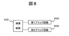
- FIG. 8 is a functional block diagram of the magnetic sensor according to the second embodiment.
- the magnetic sensor according to the second embodiment includes a first bridge circuit 200 composed of two pairs of magnetoresistive elements in which the magnetization directions of the ferromagnetic pinned layer are set to 0 ° and 180 °, and the ferromagnetic pinned layer. And a second bridge circuit 300 composed of two pairs of magnetoresistive elements in which the magnetization directions of the layers are set to 90 ° and 270 °. Further, an arithmetic device 100 is provided that calculates the absolute angle of the angle detection object using the output of each bridge circuit.
- FIG. 9 is an equivalent circuit diagram of each bridge circuit.
- the first bridge circuit 200 includes magnetoresistive elements 31a, 31b, 31c, and 31d.
- the second bridge circuit 300 includes magnetoresistive elements 32a, 32b, 32c, and 32d.
- the arrow shown in the equivalent circuit represents the direction of magnetization of the ferromagnetic fixed layer (here, focusing on the magnetization direction of the Co 90 Fe 10 (2.5) layer in contact with the Cu (2.1) layer). Yes.
- FIG. 10 is a diagram illustrating the outputs of the first bridge circuit 200 and the second bridge circuit 300.
- the output waveform of each bridge circuit is a sine wave waveform whose phase is shifted by 90 °.
- the magnetic sensor according to the second embodiment is manufactured using the magnetoresistive effect element manufactured by the method described in the first embodiment.
- FIG. 11 is a schematic diagram of a magnetic sensor according to Embodiment 3 of the present invention. In the figure, for the sake of simplicity of description, an example in which four textures are formed on the same substrate is shown.
- the part is composed.
- a three-dimensional magnetic sensor can be constituted.
- the magnetic detection unit that detects magnetism in the z-axis direction in FIG. 11 does not necessarily have to be a magnetoresistive element, and any magnetic detection method can be used.
- a three-dimensional magnetic sensor having the same effect as the magnetoresistive effect element described in the first and second embodiments can be obtained.
- the configuration of the GMR film using the self-pinned ferromagnetic fixed layer not including the antiferromagnetic layer has been described.
- a GMR film using an irregular antiferromagnetic layer exchange-coupled with the ferromagnetic layer in contact with the ferromagnetic layer can be manufactured by the same manufacturing method as in Example 1 without applying heat treatment while applying a magnetic field. it can.
- Examples of the material of the antiferromagnetic layer include Mn—X (X: Ru, Rh, Pd, Re, Os, Ir, Pt, Au, Cr, Fe, and Ni, such as MnIr and MnRu. ) Can be used.
- the GMR film according to the fourth embodiment is Ta (3 nm) / Ru (2) / Mn 80 Ir 20 (6) / Co 75 Fe 25 (2.4) / Ru (0.35) / Co 90 Fe 10 ( 2.5) / Cu (2.1) / Co 90 Fe 10 (1) / Ni 85 Fe 15 (2) / Cu (0.6) / Ta (2).
- the magnetoresistive effect element using the GMR film configuration in the fourth embodiment can also be manufactured by the same method as in the first embodiment.
- ion beam etching conditions specifically, the angle formed between the normal direction of the substrate and the ion beam incident direction, ion gas types, ion acceleration conditions, and the like are different from those in the first embodiment. And examined. As a result of examination, the period of the texture irregularities is 2 nm or more and 1 A range of 00 nm or less was found to be suitable.
- the amplitude of the texture irregularities is preferably in the range of 0.5 nm to 2.5 nm. As the amplitude of the irregularities increased, the magnitude of uniaxial magnetic anisotropy induced in the ferromagnetic pinned layer formed on the texture monotonously increased. In particular, the amplitude increased sharply from 0.5 nm and tended to be saturated around 2.8 nm.
- each layer is about 2 to 3 nm
- the impression that the uneven amplitude is 2.5 nm gives an impression that it is too large.
- the unevenness of about 1 nm seen in the texture attenuates as the GMR film underlayer is deposited, and an almost uneven structure is formed on the outermost surface of the ferromagnetic pinned layer on the underlayer side. unacceptable.
- the unevenness of the interface is caused by a decrease in antiferromagnetic interlayer coupling via the Ru layer in the ferromagnetic pinned layer, and an increase in ferromagnetic interlayer coupling between the ferromagnetic pinned layer and the ferromagnetic free layer. Invite. Therefore, it is very convenient that the unevenness of the interface is small in the region above the ferromagnetic pinned layer on the base layer side as shown in FIG.
- the uniaxial magnetic anisotropy induced by texture formation the more stable the magnetization of the ferromagnetic pinned layer. Therefore, in the sixth embodiment, the uniaxial magnetic anisotropy was evaluated by changing the composition of the ferromagnetic fixed layer from that in the first embodiment. Note that Co 75 Fe 25 (2.4 nm) is used in the ferromagnetic fixed layer in the first embodiment.
- Co 50 Fe 50 was used as the composition of the ferromagnetic fixed layer, an anisotropic magnetic field of 24 kA / m was obtained. In the composition of Embodiment 1, it was 8 kA / m. Further, when a Co—Fe film was formed on the same texture and compared, it was found that Co 75 Fe 25 and Co 50 Fe 50 had different easy axes of magnetization by 90 °.
- the crystal structure may be an fcc (face centered cubic lattice) structure or a bcc (body centered cubic lattice) structure.
- fcc face centered cubic lattice
- bcc body centered cubic lattice
- the crystal structures of the ferromagnetic pinned layer on the underlayer side and the nonmagnetic intermediate layer side are matched. This is because a material having easy magnetization axes orthogonal to each other is selected and stacked (for example, Co 50 Fe 50 (2.1 nm) / Ru (0.35) / Co 90 Fe 10 (2.5)), This is because the magnetization of the self-pinned ferromagnetic pinned layer becomes unstable.
- Co—Fe layers are important factors for the stability of magnetization of the ferromagnetic pinned layer, and also for good MR characteristics.
- a configuration such as Co 50 Fe 50 (2.1 nm) / Ru (0.35) / Co 50 Fe 50 (1.9 nm) / Co 90 Fe 10 (1.0) is suitable.
- the ferromagnetic free layer is configured as Co 90 Fe 10 (1 nm) / Co 72 Fe 8 B 20 (7).
- the anisotropic magnetic field Hk could be 2 kA / m or less without substantially deteriorating the MR characteristics.
- the anisotropic MR effect (AMR) of the ferromagnetic free layer was reduced, and a more advantageous secondary effect could be confirmed.
- the stacking order of the layers when forming the GMR film is different from that in the first embodiment.
- the layers are laminated in the order of the ferromagnetic free layer / nonmagnetic intermediate layer / ferromagnetic pinned layer from the substrate side. Accordingly, the layer forming the texture is different from that of the first embodiment.
- FIG. 12 is a flowchart showing a method of manufacturing the magnetoresistive effect element according to the eighth embodiment. Hereinafter, each step of FIG. 12 will be described.
- the magnetic field has an angle between a predetermined reference direction (first direction) and a direction perpendicular to the reference direction (second direction), preferably an intermediate angle ⁇ between the two.
- first direction a predetermined reference direction
- second direction a direction perpendicular to the reference direction
- ⁇ an intermediate angle between the two.
- a GMR film is formed while applying.
- the magnitude of the magnetic field is set in the same manner as in step S103 of the first embodiment.
- the first direction is set to 0 ° with respect to the reference direction and the second direction is set to 90 ° as in the first embodiment.
- FIG. 12 Step S1202
- a linear first texture (first pattern) is formed in a specific part (first part) on the GMR film at an angle of 0 ° with respect to the reference direction.
- the actual texture is formed in a straight line in a direction connecting the direction of 0 ° and the direction of 180 ° with respect to the reference direction.
- an ion beam etching method may be used as in FIG.
- FIG. 12 Step S1203
- a linear second texture (second pattern) is formed at a specific position (second part different from the first part) on the GMR film at an angle of 90 ° with respect to the reference direction.
- the actual texture is formed in a straight line in the direction connecting the 90 ° direction and the 270 ° direction with respect to the reference direction.
- the ferromagnetic pinned layer of the GMR film has an easy axis in the direction connecting 0 ° and 180 ° and the direction connecting 90 ° and 270 ° depending on the directivity of the texture.
- a uniaxial magnetic anisotropy is induced.
- Steps S1204 to S1205) These steps are the same as steps S104 to S105 in FIG.
- Step S1206 At least in the process of forming the ferromagnetic pinned layer, the GMR film is formed while applying a magnetic field at an angle between 180 ° and 270 ° with respect to the reference direction, preferably at an angle ⁇ of 225 °. To do.
- the magnitude of the magnetic field is set in the same manner as in step S103 of the first embodiment.
- a linear third texture (third pattern) is formed at a specific position on the GMR film (a third part different from the first part and the second part) at an angle of 180 ° with respect to the reference direction.
- the actual texture is formed in a straight line in a direction connecting the direction of 0 ° and the direction of 180 ° with respect to the reference direction.
- a linear fourth texture (fourth pattern) is formed in a specific part (fourth part different from the first part to the third part) on the GMR at an orientation of 270 ° with respect to the reference direction.
- the actual texture is formed in a straight line in the direction connecting the 90 ° direction and the 270 ° direction with respect to the reference direction.
- the ferromagnetic pinned layer of the GMR film has an easy axis in the direction connecting 0 ° and 180 ° and the direction connecting 90 ° and 270 ° depending on the directivity of the texture.
- a uniaxial magnetic anisotropy is induced.
- FIG. 12 Steps S1209 to S1211) These steps are the same as steps S109 to S111 in FIG.
- the configuration of the GMR film is Ta (3 nm) / Ru (2) / Ni 85 Fe 15 (2) / Co 90 Fe 10 (1) / Cu (2.1) / Co 90 Fe 10 (2.5) / Ru (0.35) / Co 75 Fe 25 (2.4) / Ta (2) or the like can be used.
- the order of the manufacturing method flow is changed because the order of stacking the GMR films is reversed.
- the essential method is the same as that of the first embodiment. You can think of it. Therefore, since the technique described in Embodiment 1 can be diverted for the detailed procedure of each process, detailed description is abbreviate
- the procedure of performing the texture forming step four times has been described, but the texture forming step may be performed twice.
- a GMR film is selectively formed only on the part.
- 31a to 31d, 32a to 32d magnetoresistive effect element, 100: arithmetic unit, 200: first bridge circuit, 300: second bridge circuit.
Landscapes
- Engineering & Computer Science (AREA)
- Physics & Mathematics (AREA)
- Chemical & Material Sciences (AREA)
- Nanotechnology (AREA)
- General Physics & Mathematics (AREA)
- Condensed Matter Physics & Semiconductors (AREA)
- Crystallography & Structural Chemistry (AREA)
- Manufacturing & Machinery (AREA)
- Hall/Mr Elements (AREA)
- Measuring Magnetic Variables (AREA)
- Magnetic Heads (AREA)
Abstract
Priority Applications (4)
| Application Number | Priority Date | Filing Date | Title |
|---|---|---|---|
| US13/321,896 US8779764B2 (en) | 2009-07-13 | 2010-07-13 | Method for producing magnetoresistive effect element, magnetic sensor, rotation-angle detection device |
| JP2011522809A JP5516584B2 (ja) | 2009-07-13 | 2010-07-13 | 磁気抵抗効果素子の製造方法、磁気センサ、回転角度検出装置 |
| DE112010002899T DE112010002899T5 (de) | 2009-07-13 | 2010-07-13 | Verfahren zur Herstellung eines Magnetowiderstandseffektelements, eines Magnetsensors, einer Drehwinkel-Erfassungsvorrichtung |
| US14/330,059 US9488702B2 (en) | 2009-07-13 | 2014-07-14 | Method for producing magneto-resistive effect element, magnetic sensor, rotation-angle detection device |
Applications Claiming Priority (2)
| Application Number | Priority Date | Filing Date | Title |
|---|---|---|---|
| JP2009164964 | 2009-07-13 | ||
| JP2009-164964 | 2009-07-13 |
Related Child Applications (2)
| Application Number | Title | Priority Date | Filing Date |
|---|---|---|---|
| US13/321,896 A-371-Of-International US8779764B2 (en) | 2009-07-13 | 2010-07-13 | Method for producing magnetoresistive effect element, magnetic sensor, rotation-angle detection device |
| US14/330,059 Division US9488702B2 (en) | 2009-07-13 | 2014-07-14 | Method for producing magneto-resistive effect element, magnetic sensor, rotation-angle detection device |
Publications (1)
| Publication Number | Publication Date |
|---|---|
| WO2011007767A1 true WO2011007767A1 (fr) | 2011-01-20 |
Family
ID=43449374
Family Applications (1)
| Application Number | Title | Priority Date | Filing Date |
|---|---|---|---|
| PCT/JP2010/061806 WO2011007767A1 (fr) | 2009-07-13 | 2010-07-13 | Procédé de production d'un élément à effet magnéto-résistif, capteur magnétique, dispositif de détection d'angle de rotation |
Country Status (4)
| Country | Link |
|---|---|
| US (2) | US8779764B2 (fr) |
| JP (1) | JP5516584B2 (fr) |
| DE (1) | DE112010002899T5 (fr) |
| WO (1) | WO2011007767A1 (fr) |
Cited By (8)
| Publication number | Priority date | Publication date | Assignee | Title |
|---|---|---|---|---|
| DE102012201384A1 (de) * | 2012-01-31 | 2013-08-01 | Continental Automotive Gmbh | Magnetoresistiver Sensor |
| US9529060B2 (en) | 2014-01-09 | 2016-12-27 | Allegro Microsystems, Llc | Magnetoresistance element with improved response to magnetic fields |
| US9797962B2 (en) | 2012-10-26 | 2017-10-24 | Soochow University | Sensor element based on magneto-thermoelectric effect, and realizing method thereof |
| US9812637B2 (en) | 2015-06-05 | 2017-11-07 | Allegro Microsystems, Llc | Spin valve magnetoresistance element with improved response to magnetic fields |
| US10050193B1 (en) | 2017-06-05 | 2018-08-14 | Allegro Microsystems, Llc | Magnetoresistance structure patterning |
| US10620279B2 (en) | 2017-05-19 | 2020-04-14 | Allegro Microsystems, Llc | Magnetoresistance element with increased operational range |
| US11022661B2 (en) | 2017-05-19 | 2021-06-01 | Allegro Microsystems, Llc | Magnetoresistance element with increased operational range |
| US11719771B1 (en) | 2022-06-02 | 2023-08-08 | Allegro Microsystems, Llc | Magnetoresistive sensor having seed layer hysteresis suppression |
Families Citing this family (10)
| Publication number | Priority date | Publication date | Assignee | Title |
|---|---|---|---|---|
| EP3385739B1 (fr) * | 2015-12-03 | 2021-10-06 | Alps Alpine Co., Ltd. | Dispositif de détection magnétique |
| CN106871778B (zh) * | 2017-02-23 | 2019-11-22 | 江苏多维科技有限公司 | 一种单芯片双轴磁电阻角度传感器 |
| US10777345B2 (en) | 2018-02-21 | 2020-09-15 | Allegro Microsystems, Llc | Spin valve with bias alignment |
| US10840001B2 (en) | 2018-03-06 | 2020-11-17 | Allegro Microsystems, Llc | Magnetoresistance element with extended linear response to magnetic fields |
| US11193989B2 (en) | 2018-07-27 | 2021-12-07 | Allegro Microsystems, Llc | Magnetoresistance assembly having a TMR element disposed over or under a GMR element |
| US11127518B2 (en) | 2019-08-30 | 2021-09-21 | Allegro Microsystems, Llc | Tunnel magnetoresistance (TMR) element having cobalt iron and tantalum layers |
| US11217626B2 (en) | 2019-08-30 | 2022-01-04 | Allegro Microsystems, Llc | Dual tunnel magnetoresistance (TMR) element structure |
| US11187764B2 (en) | 2020-03-20 | 2021-11-30 | Allegro Microsystems, Llc | Layout of magnetoresistance element |
| US11782103B2 (en) | 2020-06-12 | 2023-10-10 | Allegro Microsystems, Llc | Dual double-pinned spin valve element having magnet bias with increased linear range |
| US11630168B2 (en) | 2021-02-03 | 2023-04-18 | Allegro Microsystems, Llc | Linear sensor with dual spin valve element having reference layers with magnetization directions different from an external magnetic field direction |
Citations (6)
| Publication number | Priority date | Publication date | Assignee | Title |
|---|---|---|---|---|
| JP2003502876A (ja) * | 1999-06-18 | 2003-01-21 | コーニンクレッカ フィリップス エレクトロニクス エヌ ヴィ | 不可逆特性を持つ磁気システムおよびこの種システムを作成し修理し操作する方法 |
| JP2006172686A (ja) * | 2004-11-22 | 2006-06-29 | Fujitsu Ltd | 磁気記録媒体およびその製造方法、磁気記憶装置、基板、テクスチャ形成装置 |
| JP2006308573A (ja) * | 2005-03-28 | 2006-11-09 | Yamaha Corp | 三軸磁気センサおよびその製造方法 |
| JP2007317734A (ja) * | 2006-05-23 | 2007-12-06 | Sony Corp | 記憶素子及びメモリ |
| JP2008306112A (ja) * | 2007-06-11 | 2008-12-18 | Hitachi Metals Ltd | 磁気抵抗効果膜、磁気センサ及び回転角度検出装置 |
| JP2009085953A (ja) * | 2007-09-28 | 2009-04-23 | Magic Technologies Inc | 磁気デバイスの製造方法および磁場角度センサの製造方法 |
Family Cites Families (37)
| Publication number | Priority date | Publication date | Assignee | Title |
|---|---|---|---|---|
| JPS599987A (ja) * | 1982-07-08 | 1984-01-19 | Matsushita Electric Ind Co Ltd | 磁気抵抗効果素子 |
| US4604176A (en) | 1984-03-30 | 1986-08-05 | Sperry Corporation | Method of improving magnetoresistive effect in thin magnetic film |
| JPH0333934A (ja) | 1989-06-29 | 1991-02-14 | Nec Corp | レジスタ退避復帰方式 |
| JPH0340750A (ja) | 1989-07-07 | 1991-02-21 | Mitsubishi Electric Corp | 超電導回転電機の冷媒給排装置 |
| US5583725A (en) | 1994-06-15 | 1996-12-10 | International Business Machines Corporation | Spin valve magnetoresistive sensor with self-pinned laminated layer and magnetic recording system using the sensor |
| DE19830344C2 (de) | 1998-07-07 | 2003-04-10 | Ipht Jena Inst Fuer Physikalis | Verfahren zum Einstellen der Magnetisierung der Biasschicht eines magneto-resistiven Sensorelements, demgemäß bearbeitetes Sensorelement sowie zur Durchführung des Verfahrens geeignetes Sensorsubstrat |
| JP3623366B2 (ja) * | 1998-07-17 | 2005-02-23 | アルプス電気株式会社 | 巨大磁気抵抗効果素子を備えた磁界センサおよびその製造方法と製造装置 |
| US6424506B1 (en) | 1998-07-21 | 2002-07-23 | Alps Electric Co., Ltd. | Spin-valve magnetoresistive thin film element |
| JP3040750B2 (ja) | 1998-07-21 | 2000-05-15 | アルプス電気株式会社 | スピンバルブ型薄膜素子及びこのスピンバルブ型薄膜素子を用いた薄膜磁気ヘッド |
| US6252796B1 (en) | 1998-08-14 | 2001-06-26 | U.S. Philips Corporation | Device comprising a first and a second ferromagnetic layer separated by a non-magnetic spacer layer |
| DE19949713C2 (de) | 1999-10-15 | 2001-08-16 | Bosch Gmbh Robert | Magnetoresistives Schichtsystem |
| JP3872262B2 (ja) * | 2000-01-25 | 2007-01-24 | セイコーインスツル株式会社 | 電子方位計及び電子方位計付電子時計 |
| US6448763B1 (en) * | 2001-01-10 | 2002-09-10 | Siemens Corporation | System for magnetization to produce linear change in field angle |
| JP3498737B2 (ja) * | 2001-01-24 | 2004-02-16 | ヤマハ株式会社 | 磁気センサの製造方法 |
| JP3839697B2 (ja) * | 2001-10-17 | 2006-11-01 | アルプス電気株式会社 | 回転角度センサ |
| JP4016857B2 (ja) * | 2002-10-18 | 2007-12-05 | ヤマハ株式会社 | 磁気センサ及びその製造方法 |
| DE10342260B4 (de) * | 2003-09-11 | 2014-11-20 | Meas Deutschland Gmbh | Magnetoresistiver Sensor in Form einer Halb- oder Vollbrückenschaltung |
| KR100698413B1 (ko) * | 2004-09-28 | 2007-03-23 | 야마하 가부시키가이샤 | 거대 자기저항 소자를 이용한 자기 센서 및 그 제조 방법 |
| DE102005047413B8 (de) * | 2005-02-23 | 2012-05-10 | Infineon Technologies Ag | Magnetfeldsensorelement und Verfahren zum Durchführen eines On-Wafer-Funktionstests, sowie Verfahren zur Herstellung von Magnetfeldsensorelementen und Verfahren zur Herstellung von Magnetfeldsensorelementen mit On-Wafer-Funktionstest |
| TWI313078B (en) * | 2005-03-17 | 2009-08-01 | Yamaha Corporatio | Magnetic sensor and manufacturing method therefor |
| WO2006098431A1 (fr) | 2005-03-17 | 2006-09-21 | Yamaha Corporation | Capteur magnétique à 3 axes et procédé de fabrication de celui-ci |
| JP2006276983A (ja) * | 2005-03-28 | 2006-10-12 | Yamaha Corp | ポインティングデバイス用の磁気センサ |
| DE102005037036B4 (de) | 2005-08-06 | 2007-07-12 | Sensitec Gmbh | Magnetoresistiver Sensor mit Offsetkorrektur und dafür geeignetes Verfahren |
| US7564659B2 (en) | 2005-08-09 | 2009-07-21 | Hitachi Global Storage Technologies Netherlands B.V. | Magnetoresistive sensor having an anisotropic pinned layer for pinning improvement |
| US7525775B2 (en) | 2005-11-17 | 2009-04-28 | Hitachi Global Storage Technologies Netherlands B.V. | Oblique angle etched underlayers for improved exchange biased structures in a magnetoresitive sensor |
| US7446984B2 (en) | 2005-12-14 | 2008-11-04 | Hitachi Global Storage Technologies Netherlands B.V. | Magnetic random access memory (MRAM) having increased reference layer anisotropy through ion beam etch of magnetic layers |
| JP2007299880A (ja) * | 2006-04-28 | 2007-11-15 | Toshiba Corp | 磁気抵抗効果素子,および磁気抵抗効果素子の製造方法 |
| JP4991322B2 (ja) * | 2006-10-30 | 2012-08-01 | 日立オートモティブシステムズ株式会社 | Gmr素子を用いた変位センサ,gmr素子を用いた角度検出センサ及びそれらに用いる半導体装置 |
| US7900342B2 (en) | 2007-02-23 | 2011-03-08 | Hitachi Global Storage Technologies Netherlands, B.V. | Methods of fabricating magnetoresistance sensors pinned by an etch induced magnetic anisotropy |
| DE102007032867B4 (de) * | 2007-07-13 | 2009-12-24 | Infineon Technologies Ag | Magnetoresistive Magnetfeldsensorstrukturen und Herstellungsverfahren |
| US20090059444A1 (en) * | 2007-08-30 | 2009-03-05 | Freescale Semiconductor, Inc. | Methods and structures for an integrated two-axis magnetic field sensor |
| US8015694B2 (en) | 2007-12-18 | 2011-09-13 | Hitachi Global Storage Technologies Netherlands B.V. | Method for making a scissoring-type current-perpendicular-to-the-plane (CPP) magnetoresistive sensor |
| JP5170679B2 (ja) * | 2008-01-29 | 2013-03-27 | 日立金属株式会社 | 磁気センサおよび回転角度検出装置 |
| US8242776B2 (en) * | 2008-03-26 | 2012-08-14 | Everspin Technologies, Inc. | Magnetic sensor design for suppression of barkhausen noise |
| US7965077B2 (en) * | 2008-05-08 | 2011-06-21 | Everspin Technologies, Inc. | Two-axis magnetic field sensor with multiple pinning directions |
| EP2323189B1 (fr) * | 2008-09-12 | 2019-01-30 | Hitachi Metals, Ltd. | Utilisation d'une couche auto-fixée à vanne de spin à effet de magnétorésistance |
| JP4807535B2 (ja) * | 2009-07-31 | 2011-11-02 | Tdk株式会社 | 磁気センサ |
-
2010
- 2010-07-13 WO PCT/JP2010/061806 patent/WO2011007767A1/fr active Application Filing
- 2010-07-13 US US13/321,896 patent/US8779764B2/en not_active Expired - Fee Related
- 2010-07-13 JP JP2011522809A patent/JP5516584B2/ja active Active
- 2010-07-13 DE DE112010002899T patent/DE112010002899T5/de not_active Withdrawn
-
2014
- 2014-07-14 US US14/330,059 patent/US9488702B2/en not_active Expired - Fee Related
Patent Citations (6)
| Publication number | Priority date | Publication date | Assignee | Title |
|---|---|---|---|---|
| JP2003502876A (ja) * | 1999-06-18 | 2003-01-21 | コーニンクレッカ フィリップス エレクトロニクス エヌ ヴィ | 不可逆特性を持つ磁気システムおよびこの種システムを作成し修理し操作する方法 |
| JP2006172686A (ja) * | 2004-11-22 | 2006-06-29 | Fujitsu Ltd | 磁気記録媒体およびその製造方法、磁気記憶装置、基板、テクスチャ形成装置 |
| JP2006308573A (ja) * | 2005-03-28 | 2006-11-09 | Yamaha Corp | 三軸磁気センサおよびその製造方法 |
| JP2007317734A (ja) * | 2006-05-23 | 2007-12-06 | Sony Corp | 記憶素子及びメモリ |
| JP2008306112A (ja) * | 2007-06-11 | 2008-12-18 | Hitachi Metals Ltd | 磁気抵抗効果膜、磁気センサ及び回転角度検出装置 |
| JP2009085953A (ja) * | 2007-09-28 | 2009-04-23 | Magic Technologies Inc | 磁気デバイスの製造方法および磁場角度センサの製造方法 |
Cited By (12)
| Publication number | Priority date | Publication date | Assignee | Title |
|---|---|---|---|---|
| DE102012201384A1 (de) * | 2012-01-31 | 2013-08-01 | Continental Automotive Gmbh | Magnetoresistiver Sensor |
| US9797962B2 (en) | 2012-10-26 | 2017-10-24 | Soochow University | Sensor element based on magneto-thermoelectric effect, and realizing method thereof |
| US9529060B2 (en) | 2014-01-09 | 2016-12-27 | Allegro Microsystems, Llc | Magnetoresistance element with improved response to magnetic fields |
| US9804234B2 (en) | 2014-01-09 | 2017-10-31 | Allegro Microsystems, Llc | Magnetoresistance element with an improved seed layer to promote an improved response to magnetic fields |
| US9922673B2 (en) | 2014-01-09 | 2018-03-20 | Allegro Microsystems, Llc | Magnetoresistance element with improved response to magnetic fields |
| US10347277B2 (en) | 2014-01-09 | 2019-07-09 | Allegro Microsystems, Llc | Magnetoresistance element with improved response to magnetic fields |
| US9812637B2 (en) | 2015-06-05 | 2017-11-07 | Allegro Microsystems, Llc | Spin valve magnetoresistance element with improved response to magnetic fields |
| US10620279B2 (en) | 2017-05-19 | 2020-04-14 | Allegro Microsystems, Llc | Magnetoresistance element with increased operational range |
| US11002807B2 (en) | 2017-05-19 | 2021-05-11 | Allegro Microsystems, Llc | Magnetoresistance element with increased operational range |
| US11022661B2 (en) | 2017-05-19 | 2021-06-01 | Allegro Microsystems, Llc | Magnetoresistance element with increased operational range |
| US10050193B1 (en) | 2017-06-05 | 2018-08-14 | Allegro Microsystems, Llc | Magnetoresistance structure patterning |
| US11719771B1 (en) | 2022-06-02 | 2023-08-08 | Allegro Microsystems, Llc | Magnetoresistive sensor having seed layer hysteresis suppression |
Also Published As
| Publication number | Publication date |
|---|---|
| JPWO2011007767A1 (ja) | 2012-12-27 |
| US20140320117A1 (en) | 2014-10-30 |
| US8779764B2 (en) | 2014-07-15 |
| US9488702B2 (en) | 2016-11-08 |
| DE112010002899T5 (de) | 2012-06-14 |
| JP5516584B2 (ja) | 2014-06-11 |
| US20120112741A1 (en) | 2012-05-10 |
Similar Documents
| Publication | Publication Date | Title |
|---|---|---|
| JP5516584B2 (ja) | 磁気抵抗効果素子の製造方法、磁気センサ、回転角度検出装置 | |
| JP5734657B2 (ja) | セルフピン型スピンバルブ磁気抵抗効果膜とそれを用いた磁気センサおよび回転角度検出装置 | |
| TWI244785B (en) | Magnetic sensor, production process of the magnetic sensor and magnetic array suitable for the production process | |
| US20020142490A1 (en) | Magnetic sensor and method of producing the same | |
| JP5295163B2 (ja) | 磁界検出装置およびそれを調整する方法 | |
| JP2008286739A (ja) | 磁界検出器及び回転角度検出装置 | |
| WO2012090631A1 (fr) | Capteur de courant proportionnel électromagnétique | |
| CN111630402A (zh) | 磁检测装置及其制造方法 | |
| JP7022764B2 (ja) | 磁界印加バイアス膜ならびにこれを用いた磁気検出素子および磁気検出装置 | |
| JP2008306112A (ja) | 磁気抵抗効果膜、磁気センサ及び回転角度検出装置 | |
| JP2006269955A (ja) | 磁界検出装置 | |
| JP4985522B2 (ja) | 磁界測定方法及び磁気センサ | |
| CN113383243A (zh) | 用于磁阻磁场传感器的相邻层结构的布置、磁阻磁场传感器及其生产方法 | |
| JP2012119613A (ja) | 磁気検出素子及びそれを用いた磁気センサ | |
| JPWO2011111649A1 (ja) | 磁気センサ及びその製造方法 | |
| JP2012063232A (ja) | 磁界検出装置の製造方法および磁界検出装置 | |
| US10998131B2 (en) | Multilayer device having an improved antiferromagnetic pinning layer and a corresponding manufacturing method | |
| WO2015008718A1 (fr) | Capteur magnétique et son procédé de fabrication | |
| JP2016157818A (ja) | 磁気センサおよび電流センサ | |
| JP3835445B2 (ja) | 磁気センサ | |
| JP7023428B1 (ja) | 磁気センサ素子、磁気センサおよび磁気センサ装置 | |
| JP6204391B2 (ja) | 磁気センサおよび電流センサ | |
| WO2011033981A1 (fr) | Procédé de production d'un détecteur magnétique | |
| JP2005123334A (ja) | 磁気抵抗効果膜の製造方法 | |
| JP2022538384A (ja) | 異方性磁場の低い2次元外部磁場を検知する磁場センサ |
Legal Events
| Date | Code | Title | Description |
|---|---|---|---|
| 121 | Ep: the epo has been informed by wipo that ep was designated in this application |
Ref document number: 10799825 Country of ref document: EP Kind code of ref document: A1 |
|
| ENP | Entry into the national phase |
Ref document number: 2011522809 Country of ref document: JP Kind code of ref document: A |
|
| WWE | Wipo information: entry into national phase |
Ref document number: 13321896 Country of ref document: US Ref document number: 112010002899 Country of ref document: DE Ref document number: 1120100028990 Country of ref document: DE |
|
| 122 | Ep: pct application non-entry in european phase |
Ref document number: 10799825 Country of ref document: EP Kind code of ref document: A1 |