WO2010126078A1 - 偏光子の製造方法 - Google Patents
偏光子の製造方法 Download PDFInfo
- Publication number
- WO2010126078A1 WO2010126078A1 PCT/JP2010/057542 JP2010057542W WO2010126078A1 WO 2010126078 A1 WO2010126078 A1 WO 2010126078A1 JP 2010057542 W JP2010057542 W JP 2010057542W WO 2010126078 A1 WO2010126078 A1 WO 2010126078A1
- Authority
- WO
- WIPO (PCT)
- Prior art keywords
- polarizer
- layer
- absorbance
- polyvinyl alcohol
- stretching
- Prior art date
Links
Images


Classifications
-
- C—CHEMISTRY; METALLURGY
- C08—ORGANIC MACROMOLECULAR COMPOUNDS; THEIR PREPARATION OR CHEMICAL WORKING-UP; COMPOSITIONS BASED THEREON
- C08J—WORKING-UP; GENERAL PROCESSES OF COMPOUNDING; AFTER-TREATMENT NOT COVERED BY SUBCLASSES C08B, C08C, C08F, C08G or C08H
- C08J5/00—Manufacture of articles or shaped materials containing macromolecular substances
- C08J5/18—Manufacture of films or sheets
-
- G—PHYSICS
- G02—OPTICS
- G02B—OPTICAL ELEMENTS, SYSTEMS OR APPARATUS
- G02B5/00—Optical elements other than lenses
- G02B5/30—Polarising elements
-
- G—PHYSICS
- G02—OPTICS
- G02B—OPTICAL ELEMENTS, SYSTEMS OR APPARATUS
- G02B1/00—Optical elements characterised by the material of which they are made; Optical coatings for optical elements
- G02B1/08—Optical elements characterised by the material of which they are made; Optical coatings for optical elements made of polarising materials
-
- G—PHYSICS
- G02—OPTICS
- G02B—OPTICAL ELEMENTS, SYSTEMS OR APPARATUS
- G02B5/00—Optical elements other than lenses
- G02B5/30—Polarising elements
- G02B5/3025—Polarisers, i.e. arrangements capable of producing a definite output polarisation state from an unpolarised input state
- G02B5/3033—Polarisers, i.e. arrangements capable of producing a definite output polarisation state from an unpolarised input state in the form of a thin sheet or foil, e.g. Polaroid
-
- G—PHYSICS
- G02—OPTICS
- G02F—OPTICAL DEVICES OR ARRANGEMENTS FOR THE CONTROL OF LIGHT BY MODIFICATION OF THE OPTICAL PROPERTIES OF THE MEDIA OF THE ELEMENTS INVOLVED THEREIN; NON-LINEAR OPTICS; FREQUENCY-CHANGING OF LIGHT; OPTICAL LOGIC ELEMENTS; OPTICAL ANALOGUE/DIGITAL CONVERTERS
- G02F1/00—Devices or arrangements for the control of the intensity, colour, phase, polarisation or direction of light arriving from an independent light source, e.g. switching, gating or modulating; Non-linear optics
- G02F1/01—Devices or arrangements for the control of the intensity, colour, phase, polarisation or direction of light arriving from an independent light source, e.g. switching, gating or modulating; Non-linear optics for the control of the intensity, phase, polarisation or colour
- G02F1/13—Devices or arrangements for the control of the intensity, colour, phase, polarisation or direction of light arriving from an independent light source, e.g. switching, gating or modulating; Non-linear optics for the control of the intensity, phase, polarisation or colour based on liquid crystals, e.g. single liquid crystal display cells
- G02F1/133—Constructional arrangements; Operation of liquid crystal cells; Circuit arrangements
- G02F1/1333—Constructional arrangements; Manufacturing methods
- G02F1/1335—Structural association of cells with optical devices, e.g. polarisers or reflectors
-
- B—PERFORMING OPERATIONS; TRANSPORTING
- B32—LAYERED PRODUCTS
- B32B—LAYERED PRODUCTS, i.e. PRODUCTS BUILT-UP OF STRATA OF FLAT OR NON-FLAT, e.g. CELLULAR OR HONEYCOMB, FORM
- B32B2457/00—Electrical equipment
- B32B2457/20—Displays, e.g. liquid crystal displays, plasma displays
- B32B2457/202—LCD, i.e. liquid crystal displays
-
- C—CHEMISTRY; METALLURGY
- C08—ORGANIC MACROMOLECULAR COMPOUNDS; THEIR PREPARATION OR CHEMICAL WORKING-UP; COMPOSITIONS BASED THEREON
- C08J—WORKING-UP; GENERAL PROCESSES OF COMPOUNDING; AFTER-TREATMENT NOT COVERED BY SUBCLASSES C08B, C08C, C08F, C08G or C08H
- C08J2329/00—Characterised by the use of homopolymers or copolymers of compounds having one or more unsaturated aliphatic radicals, each having only one carbon-to-carbon double bond, and at least one being terminated by an alcohol, ether, aldehydo, ketonic, acetal, or ketal radical; Hydrolysed polymers of esters of unsaturated alcohols with saturated carboxylic acids; Derivatives of such polymer
- C08J2329/02—Homopolymers or copolymers of unsaturated alcohols
- C08J2329/04—Polyvinyl alcohol; Partially hydrolysed homopolymers or copolymers of esters of unsaturated alcohols with saturated carboxylic acids
-
- C—CHEMISTRY; METALLURGY
- C08—ORGANIC MACROMOLECULAR COMPOUNDS; THEIR PREPARATION OR CHEMICAL WORKING-UP; COMPOSITIONS BASED THEREON
- C08J—WORKING-UP; GENERAL PROCESSES OF COMPOUNDING; AFTER-TREATMENT NOT COVERED BY SUBCLASSES C08B, C08C, C08F, C08G or C08H
- C08J2385/00—Characterised by the use of macromolecular compounds obtained by reactions forming in the main chain of the macromolecule a linkage containing atoms other than silicon, sulfur, nitrogen, oxygen, and carbon; Derivatives of such polymers
- C08J2385/04—Characterised by the use of macromolecular compounds obtained by reactions forming in the main chain of the macromolecule a linkage containing atoms other than silicon, sulfur, nitrogen, oxygen, and carbon; Derivatives of such polymers containing boron
-
- C—CHEMISTRY; METALLURGY
- C08—ORGANIC MACROMOLECULAR COMPOUNDS; THEIR PREPARATION OR CHEMICAL WORKING-UP; COMPOSITIONS BASED THEREON
- C08J—WORKING-UP; GENERAL PROCESSES OF COMPOUNDING; AFTER-TREATMENT NOT COVERED BY SUBCLASSES C08B, C08C, C08F, C08G or C08H
- C08J2429/00—Characterised by the use of homopolymers or copolymers of compounds having one or more unsaturated aliphatic radicals, each having only one carbon-to-carbon double bond, and at least one being terminated by an alcohol, ether, aldehydo, ketonic, acetal, or ketal radical; Hydrolysed polymers of esters of unsaturated alcohols with saturated carboxylic acids; Derivatives of such polymer
- C08J2429/02—Homopolymers or copolymers of unsaturated alcohols
- C08J2429/04—Polyvinyl alcohol; Partially hydrolysed homopolymers or copolymers of esters of unsaturated alcohols with saturated carboxylic acids
-
- Y—GENERAL TAGGING OF NEW TECHNOLOGICAL DEVELOPMENTS; GENERAL TAGGING OF CROSS-SECTIONAL TECHNOLOGIES SPANNING OVER SEVERAL SECTIONS OF THE IPC; TECHNICAL SUBJECTS COVERED BY FORMER USPC CROSS-REFERENCE ART COLLECTIONS [XRACs] AND DIGESTS
- Y10—TECHNICAL SUBJECTS COVERED BY FORMER USPC
- Y10T—TECHNICAL SUBJECTS COVERED BY FORMER US CLASSIFICATION
- Y10T428/00—Stock material or miscellaneous articles
- Y10T428/26—Web or sheet containing structurally defined element or component, the element or component having a specified physical dimension
- Y10T428/263—Coating layer not in excess of 5 mils thick or equivalent
- Y10T428/264—Up to 3 mils
- Y10T428/265—1 mil or less
Definitions
- the present invention relates to a method for producing a polarizer comprising a polyvinyl alcohol resin layer containing iodine.
- a manufacturing method is known in which a polyvinyl alcohol film is dyed with a dye-containing dye solution and then stretched to obtain a polarizer (for example, Patent Document 1).
- the dyed and stretched film is immersed in an aqueous potassium iodide solution to perform iodine ion impregnation treatment, and further immersed in an alcohol solution to perform an alcohol solution immersion treatment.
- the polarizer obtained by this production method has a small yellowishness and little hue change even in a heating environment.
- the reason for the small yellowness is that the absorbance is almost constant in the entire wavelength region of visible light.
- the above polarizer has a problem that the degree of polarization is low.
- a polyvinyl alcohol film is dyed with a dyeing solution containing iodine, then stretched, immersed in an aqueous potassium iodide solution to be impregnated with iodine ions, and further immersed in an alcoholic solution to obtain an alcoholic solution.
- a method for performing an immersion treatment is known.
- the polarizer obtained by this manufacturing method has a problem that the degree of polarization is low.
- the present invention provides a method for producing a polarizer having a high degree of polarization in a polarizer comprising a polyvinyl alcohol-based resin layer containing iodine.
- the gist of the present invention is as follows.
- the present invention is a method for producing a polarizer comprising a polyvinyl alcohol-based resin layer containing iodine and having a film thickness of 0.6 ⁇ m to 5 ⁇ m.
- the production method of the present invention includes the following steps A to C.
- Process A The process of extending
- Transmittance T 40% to 10%
- Step C A step of removing a part of iodine adsorbed on the dyed layer so that the absorbance of the dyed layer is reduced by 0.03 to 0.7. However, the absorbance of the dyed layer should not be less than 0.3.
- the production method of the present invention is characterized in that, in Step A, a polyvinyl alcohol-based resin layer is formed on a support, and the polyvinyl alcohol-based resin layer is stretched together with the support.
- the production method of the present invention is characterized in that, in step A, the stretching method is dry stretching.
- the production method of the present invention is characterized in that, in step A, the temperature during stretching (stretching temperature) is 130 ° C. to 170 ° C.
- the staining solution is an aqueous solution containing iodine and an alkali iodide or ammonium iodide.
- Step C a part of iodine adsorbed on the dyed layer is removed by immersing the dyed layer in a decolorizing solution containing alkali iodide or ammonium iodide. To do.
- the production method of the present invention further includes a step of immersing the dyed layer or the partially decolored dyed layer in a crosslinking solution containing boric acid and alkali iodide or ammonium iodide.
- the production method of the present invention further includes a step of drying the polarizer.
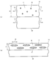
- FIGS. 1 and 2 show a case where a polyvinyl alcohol-based resin layer is formed on a support and the polyvinyl alcohol-based resin layer is stretched together with the support.
- FIG. 1A is a schematic cross-sectional view of the polyvinyl alcohol-based resin layer 10 before stretching, formed on the support 30.
- the polyvinyl alcohol-based resin layer 10 includes an amorphous part 11 and a crystallized part 12.
- the crystallized portion 12 is randomly present in the amorphous portion 11.
- An arrow 13 indicates the extending direction of the next step.
- Step A Stretching before dyeing
- the polyvinyl alcohol-based resin layer 10 is stretched together with the support 30.
- the polyvinyl alcohol-based resin layer 10 is called a stretched layer 14 after stretching.
- FIG. 1B is a schematic cross-sectional view of the stretched layer 14.
- the 1st point in the manufacturing method of this invention is extending
- Arrow 15 indicates the stretching direction.
- a polymer chain (not shown) in the stretched layer 14 is crystallized, and a crystallized portion 17 with higher orientation is generated in the amorphous portion 16.
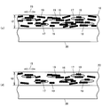
- FIG. 2C is a schematic cross-sectional view of the dyed layer 18.
- the second point in the production method of the present invention is to immerse the stretched layer 14 in a dyeing solution containing iodine to over-stain.
- the excess stain, absorbance A B determined from the tristimulus values Y, means that stained as 0.4 or more.
- the subscript B of the absorbance A B represents the process B.
- the absorbance A obtained from the tristimulus value Y of a general polarizer is about 0.37.
- the polymer chain crystallization part 17 is less dyed than the amorphous part 16.
- iodine can be sufficiently adsorbed also to the crystallization part 17 by dyeing the stretched layer 14 excessively.
- the adsorbed iodine forms a polyiodine ion complex 19 such as I 3 ⁇ or I 5 ⁇ in the dyed layer 18.
- the polyiodine ion complex 19 exhibits absorption dichroism in the visible light region (wavelength 380 nm to 780 nm).
- Step C Decolorization (removal of part of iodine)
- a part of the iodine adsorbed on the dyed layer 18 is removed. This is called decolorization.
- the dyed layer 18 is called a polarizer 20.
- Iodine is adsorbed on the dyed layer 18 in the form of a polyiodine ion complex 19.
- FIG. 2D is a schematic cross-sectional view of the polarizer 20.
- the third point in the production method of the present invention is to partially remove the polyiodine ion complex 19 from the overstained dyed layer 18.
- the dyed layer 18 is immersed in an aqueous solution of potassium iodide (decolorizing solution). At this time, the absorbance A C is to decrease from 0.03 to 0.7, to remove polyiodine ion complex 19. However, the absorbance of the dyed layer should not be less than 0.3.
- the suffix C of absorbance A C represents step C.
- the polyiodine ion complex 19 adsorbed on the amorphous part 16 is preferentially removed. As a result, a relatively large amount of the polyiodine ion complex 19 adsorbed on the crystallization part 17 remains.
- the polyiodine ion complex 19 adsorbed on the amorphous part 16 has a small contribution to the absorption dichroism.
- the polyiodine ion complex 19 adsorbed on the crystallization part 17 greatly contributes to absorption dichroism.
- the polyiodine ion complex 19 adsorbed on the amorphous part 16 and the polyiodine ion complex 19 adsorbed on the crystallization part 17 increase the absorbance in the same manner. According to the production method of the present invention, it is possible to preferentially remove the polyiodine ion complex 19 adsorbed on the amorphous part 16, which increases the absorbance even though the contribution to the absorption dichroism is small.
- the polyiodine ion complex 19 adsorbed on the crystallization part 17 having a large contribution to the absorption dichroism is relatively increased.
- a large contribution to absorption dichroism is a high degree of polarization. Therefore, by the production method of the present invention, the polarizer 20 having a high degree of polarization can be obtained for a low absorbance.
- the polarizer 20 having a high degree of polarization has a low absorbance. can get.
- FIG. 3 is a schematic view showing the production process of the present invention.
- the manufacturing method of this invention is a manufacturing method of the polarizer 20 which consists of a polyvinyl alcohol-type resin layer containing an iodine.
- the film-like untreated polyvinyl alcohol-based resin layer 10 formed on the support 30 is sequentially pulled out from the feeding section 21 together with the support 30 for processing.
- Step A the polyvinyl alcohol-based resin layer 10 is stretched while passing between the stretching rolls 22 together with the support 30 to become the stretched layer 14.
- step B the stretched layer 14 is immersed in the dyeing solution 23 containing iodine to become the dyed layer 18.
- step C the dyed layer 18 is immersed in the decolorizing solution 24 (potassium iodide aqueous solution), and a part of iodine is removed to form the polarizer 20.
- the absorbance A C of the polarizer 20 as compared to the absorbance A B Step C immediately before the dyed layer 18, decreases from 0.03 to 0.7.
- the absorbance of the dyed layer should not be less than 0.3.
- the completed polarizer 20 is taken up by the take-up unit 25.
- the manufacturing method of the present invention may include other steps as long as it includes the above-described step A, step B, and step C in this order.
- the dyed layer 18 is immersed in a crosslinking liquid (an aqueous solution containing boric acid and, if necessary, potassium iodide) between the process B and the process C, and a polyvinyl alcohol-based resin layer
- a crosslinking liquid an aqueous solution containing boric acid and, if necessary, potassium iodide
- Step A used in the present invention is a step of obtaining the stretched layer 14 by stretching the polyvinyl alcohol-based resin layer 10.
- the polyvinyl alcohol-based resin layer 10 used in the present invention is obtained by forming a polyvinyl alcohol-based resin into a layer shape.
- the polyvinyl alcohol resin layer 10 is preferably formed on the support 30.
- the polyvinyl alcohol resin is typically obtained by saponifying a polyvinyl acetate resin.
- the polyvinyl alcohol resin used in the present invention is, for example, polyvinyl alcohol or an ethylene-vinyl alcohol copolymer.
- the saponification degree of the polyvinyl alcohol resin used in the present invention is preferably 85 mol% to 100 mol%, and preferably 95 mol% to 100 mol, since the water resistance is high and high-stretching is possible. % Is more preferable, and 98 mol% to 100 mol% is more preferable.
- the degree of polymerization of the polyvinyl alcohol-based resin used in the present invention is preferably 1,000 to 10,000 because the degree of polarization can be increased by increasing the polyiodine ion complex adsorbed on the crystallization part 17.
- any known stretching method such as roll stretching or tenter stretching is used.
- the draw ratio of the polyvinyl alcohol-based resin layer 10 is usually 3 to 7 times the original length.
- the stretching of the polyvinyl alcohol-based resin layer 10 is preferably dry stretching. Dry stretching is stretching in the air. The dry stretching is preferable because the crystallinity can be higher than the wet stretching.
- the stretching temperature is preferably from 80 ° C to 170 ° C, more preferably from 130 ° C to 170 ° C.
- crystallization of the polymer chain in the polyvinyl alcohol-based resin layer 10 can be promoted.
- the polyiodine ion complex 19 adsorbed on the crystallization part 17 can be increased, and the degree of polarization can be increased. Further, by setting the stretching temperature to 170 ° C.
- the polyvinyl alcohol-based resin layer 10 is preferably stretched so that the degree of crystallinity after stretching is 20% to 50%, more preferably 32% to 50%. If the crystallinity after stretching is 20% to 50%, the polyiodine ion complex 19 adsorbed on the crystallized portion 17 increases, and the degree of polarization can be increased.
- the polyvinyl alcohol-based resin layer 10 may contain other additives other than iodine.
- additives include surfactants, antioxidants, and crosslinking agents.
- the film thickness t 0 of the polyvinyl alcohol-based resin layer 10 before stretching is usually 2 ⁇ m to 30 ⁇ m, preferably 3 ⁇ m to 15 ⁇ m. Since the polyvinyl alcohol resin layer 10 before stretching is thin, when it is difficult to stretch alone, the polyvinyl alcohol resin layer 10 is formed on the support 30 and the polyvinyl alcohol resin layer together with the support 30. 10 is stretched.
- the thickness t 1 of the stretched layer 14 is usually 0.4 ⁇ m to 7 ⁇ m, preferably 0.6 ⁇ m to 5 ⁇ m. If the film thickness t 1 of the stretched layer 14 is 5 ⁇ m or less, the target absorbance can be dyed in a short time.
- Step B In the process B used for this invention, the extending
- Absorbance A B of the dyed layer 18, more preferably 0.5 ⁇ 1.0 (T 31.6% ⁇ 10%).
- the absorbance A is calculated by the equation (1).
- A log 10 (1 / T) (1)
- the transmittance T is the value of the tristimulus value Y in the XYZ color system based on the 2-degree visual field of JIS Z 8701 (1995).
- the dyed layer 18, the absorbance A B determined from the tristimulus value Y, when placed in the range (0.4-1.0) of the specified immediately after the step B, may be subsequently changed.
- the staining solution 23 used in the present invention is usually an aqueous solution containing iodine and alkali iodide or ammonium iodide.
- alkali iodide or ammonium iodide is used to increase the solubility of iodine in water.
- the iodine content of the dyeing liquid 23 is preferably 1.1 to 5 parts by weight with respect to 100 parts by weight of water.
- potassium iodide content of the dyeing solution 23 is preferably 3 to 30 parts by weight with respect to 100 parts by weight of water.
- the temperature and immersion time of the staining solution 23 are appropriately set according to the concentration of the staining solution 23 and the thickness of the stretched layer 14 so as to satisfy the characteristics specified in the present invention.
- the temperature of the staining liquid 23 is preferably 20 ° C. to 40 ° C.
- the immersion time in the staining solution 23 is preferably 60 seconds to 1200 seconds.
- Step C In Step C used in the present invention, a part of the polyiodine ion complex 19 is removed from the dyed layer 18 obtained in Step B to obtain a polarizer 20. Removal of polyiodine ion complex 19, the absorbance A C of the polarizer 20 is, than the absorbance A B of the dyed layer 18, made to be 0.03 to 0.7 lower. However, the absorbance A B of the dyed layer is to not less than 0.3.
- the absorbance decrease ⁇ A in step C is more preferably 0.05 to 0.65.
- the absorbance decrease width ⁇ A is less than 0.03, the polarizer 20 having a high degree of polarization may not be obtained.
- an aqueous solution of alkali iodide or ammonium iodide is used.
- An aqueous solution of alkali iodide or ammonium iodide used for this purpose is referred to as decolorizing solution 24.
- the process of removing part of the polyiodine ion complex 19 from the dyed layer 18 is called decolorization.
- the dyeing layer 18 may be immersed in the decoloring solution 24, or the decoloring solution may be applied to or sprayed on the surface of the dyeing layer 18.
- the polyiodine ion complex 19 is easily eluted from the dyed layer 18 by the action of iodine ions.
- Iodine ions are obtained from alkali iodides such as potassium iodide, sodium iodide, lithium iodide, magnesium iodide, and calcium iodide.
- iodine ions are obtained from ammonium iodide.
- the iodine ion concentration of the decolorizing solution 24 is preferably sufficiently lower than the iodine ion concentration of the staining solution 23.
- the potassium iodide content of the decolorizing solution 24 is preferably 1 to 20 parts by weight with respect to 100 parts by weight of water.
- the temperature and immersion time of the decolorizing liquid 24 are appropriately set according to the film thickness of the dyed layer 18.
- the temperature of the decolorizing liquid 24 is preferably 45 ° C. to 75 ° C.
- the immersion time in the decolorizing liquid 24 is preferably 20 seconds to 600 seconds.
- the polarizer 20 obtained by the production method of the present invention comprises a polyvinyl alcohol resin layer containing iodine.
- the polyvinyl alcohol-based resin layer is stretched and dyed and has polymer chains oriented in a certain direction.
- Iodine forms a polyiodine ion complex 19 such as I 3 ⁇ or I 5 ⁇ in the polyvinyl alcohol-based resin layer, and exhibits absorption dichroism in the visible light region (wavelength 380 nm to 780 nm).
- the film thickness t 3 of the polarizer 20 is usually the same as the film thickness t 1 of the stretched layer 14, and is usually 0.4 ⁇ m to 7 ⁇ m, preferably 0.6 ⁇ m to 5 ⁇ m.
- the thickness t 3 is the degree of polarization of the polarizer 20 is 5 ⁇ m or less, and 99.9% Can do.
- Example 1 A 7% by weight aqueous solution of polyvinyl alcohol was applied to the surface of a support made of a norbornene-based resin film having a film thickness of 150 ⁇ m (ARTON manufactured by JSR) to form a polyvinyl alcohol film.
- the degree of polymerization of polyvinyl alcohol was 4,200, and the degree of saponification was 99% or more.
- the polyvinyl alcohol film and the support were dried at 80 ° C. for 8 minutes, and a polyvinyl alcohol layer having a thickness of 7 ⁇ m was formed on the support to obtain a laminate of the polyvinyl alcohol layer and the support.
- the liquid temperature of the staining liquid was 25 ° C.
- the absorbance immediately after staining was 0.602.
- the laminate of the dyed layer and the support was immersed in a decolorizing solution containing potassium iodide, and a part of the polyiodine ion complex in the dyed layer was removed.
- the liquid temperature of the decolorizing liquid was 60 ° C.
- the partially decolored dyed layer / support laminate was immersed in a crosslinking solution containing boric acid and potassium iodide.
- the immersion time in the crosslinking solution was 60 seconds.
- the liquid temperature of the crosslinking liquid was 60 ° C.
- the laminate of the dyed layer and the support subjected to the crosslinking treatment was dried at 60 ° C. for 120 seconds.
- FIG. 5 shows a graph of absorbance (A B ) versus polarization degree of the dyed layer.
- Example 2 In the same manner as in Example 1, a laminate of a polarizer (film thickness: 2.9 ⁇ m) and a support was formed. However, it differs from Example 1 in the following points. (1) The time immediately after dyeing was adjusted to 0.921 by adjusting the immersion time in the staining solution. (2) By adjusting the immersion time in the decolorizing solution, five types of samples were produced in which the absorbance of the completed polarizer was 0.359 to 0.377. A graph of the absorbance (A C ) of the polarizer versus the degree of polarization is shown in FIG. FIG. 5 shows a graph of absorbance (A B ) versus polarization degree of the dyed layer.
- Example 3 In the same manner as in Example 1, a laminate of a polarizer (film thickness: 2.9 ⁇ m) and a support was formed. However, it differs from Example 1 in the following points. (1) The immersion time in the staining solution was adjusted so that the absorbance immediately after staining was 0.420. (2) By adjusting the immersion time in the decolorizing solution, four types of samples in which the absorbance of the finished polarizer was 0.362 to 0.377 were prepared. A graph of the absorbance (A C ) of the polarizer versus the degree of polarization is shown in FIG. FIG. 5 shows a graph of absorbance (A B ) versus polarization degree of the dyed layer.
- Example 4 In the same manner as in Example 1, a laminate of a polarizer (film thickness: 2.9 ⁇ m) and a support was formed. However, it differs from Example 1 in the following points. (1) The time immediately after dyeing was adjusted to 0.959 by adjusting the immersion time in the staining solution. (2) By adjusting the immersion time in the decolorizing solution, four types of samples were produced in which the absorbance of the completed polarizer was 0.357 to 0.376. (3) The stretching temperature was 100 ° C., and the stretching ratio was 4.5 times the original length. A graph of the absorbance (A C ) of the polarizer versus the degree of polarization is shown in FIG.
- the immersion time in the decolorizing solution was 30 seconds, and the absorbance of the completed polarizer was 0.380.
- a graph of the absorbance (A C ) of the polarizer versus the degree of polarization is shown in FIG.
- Example 6 In the same manner as in Example 5, a laminate of a polarizer (film thickness: 3.5 ⁇ m) and a support was formed. However, it differs from Example 5 in the following points. (1) The immersion time in the staining solution was 600 seconds. The absorbance immediately after staining was 0.417. (2) The immersion time in the decolorizing solution was 2 seconds. The absorbance of the completed polarizer was 0.380. A graph of the absorbance (A C ) of the polarizer versus the degree of polarization is shown in FIG.
- Example 1 In the same manner as in Example 1, a laminate of a polarizer (film thickness: 2.9 ⁇ m) and a support was formed. However, it differs from Example 1 in the following points. (1) By adjusting the immersion time in the staining solution, four types of samples were produced in which the absorbance of the finished polarizer was 0.367 to 0.387. (2) No decolorization step was performed. A graph of the absorbance (A C ) of the polarizer versus the degree of polarization is shown in FIG. FIG. 5 shows a graph of absorbance (A B ) versus polarization degree of the dyed layer.
- Example 2 In the same manner as in Example 1, a laminate of a polarizer (film thickness: 2.9 ⁇ m) and a support was formed. However, it differs from Example 1 in the following points. (1) By adjusting the immersion time in the staining solution, four types of samples in which the absorbance of the completed polarizer was 0.367 to 0.384 were prepared. (2) No decolorization step was performed. (3) The stretching temperature was 100 ° C., and the stretching ratio was 4.5 times the original length. A graph of the absorbance (A C ) of the polarizer versus the degree of polarization is shown in FIG.
- FIG. 4 illustrates a graph of absorbance (A C ) versus polarization degree of a polarizer.
- Example 2 Comparing Examples 1 to 3, Example 2, Example 1, and Example 3 are in descending order of polarization degree. This is the order of decreasing absorbance due to decolorization.
- the decrease in absorbance in Example 2 is 0.544 to 0.562
- the decrease in absorbance in Example 1 is 0.225 to 0.245
- the decrease in absorbance in Example 3 is 0.043 to 0.058. Therefore, the difference in the degree of polarization in Examples 1 to 3 is considered to be due to the difference in the decrease in absorbance due to decolorization.
- the degree of polarization is higher in Example 4 than in Example 3.
- the stretching conditions of Example 4 are 100 ° C.
- Example 4 is more disadvantageous for the stretching conditions.
- the decrease in absorbance in Example 4 is 0.583 to 0.602, and the decrease in absorbance in Example 3 is 0.043 to 0.058. Therefore, Example 4 is advantageous with respect to a decrease in absorbance. Since the advantageous effect of the decrease in absorbance in Example 4 exceeded the disadvantageous effect of the stretching conditions, Example 4 is considered to have a higher degree of polarization than Example 3. (3) Examples 5 and 6 have the same stretching conditions. However, the decrease in absorbance due to decolorization is large in Example 5 (0.243) and small in Example 6 (0.037).
- Example 7 the degree of polarization differs between Example 5 and Example 6 due to the difference in absorbance decrease.
- the stretching temperature (110 ° C.) of Example 7 is lower than the stretching temperature (140 ° C.) of Examples 5 and 6. Therefore, Example 7 is considered to have a low degree of polarization.
- the reason why the degree of polarization of Comparative Examples 1, 2, and 3 is low is considered to be because no decrease in absorbance due to decolorization was performed.
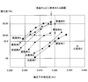
- FIG. 5 illustrates a graph of absorbance (A B ) vs. polarization degree of the dyed layer.
- the stretching conditions are both 150 ° C. and 4.8 times. Therefore, this graph represents only the effect of decreasing absorbance due to decolorization.
- This graph plots the degree of polarization when the absorbance (A C ) of the polarizer is 0.367. Therefore, the higher the absorbance (A B ) of the dyed layer, the more the absorbance decreases due to decolorization. Examples are Example 2, Example 1, and Example 3 in order of decreasing absorbance due to decolorization. In Comparative Example 1, decolorization is not performed. As can be seen from the graph, the degree of polarization increases as the absorbance decreases due to decolorization.
- the parallel transmittance is a transmittance when two polarizers manufactured under the same conditions are stacked so that the transmission axes are parallel to each other and measured.
- the orthogonal transmittance is a transmittance when two polarizers manufactured under the same conditions are stacked and measured so that the transmission axes are orthogonal to each other.
- the parallel transmittance and the orthogonal transmittance are values of the tristimulus value Y of the XYZ color system based on the two-degree visual field of JIS Z 8701 (1995).
- the polarizer of the present invention is suitably used for liquid crystal display devices such as liquid crystal televisions, computer displays, car navigation systems, mobile phones, and game machines.
Landscapes
- Physics & Mathematics (AREA)
- Chemical & Material Sciences (AREA)
- Optics & Photonics (AREA)
- General Physics & Mathematics (AREA)
- Manufacturing & Machinery (AREA)
- Engineering & Computer Science (AREA)
- Medicinal Chemistry (AREA)
- Health & Medical Sciences (AREA)
- Chemical Kinetics & Catalysis (AREA)
- Polymers & Plastics (AREA)
- Organic Chemistry (AREA)
- Materials Engineering (AREA)
- Nonlinear Science (AREA)
- Crystallography & Structural Chemistry (AREA)
- Mathematical Physics (AREA)
- Polarising Elements (AREA)
- Shaping By String And By Release Of Stress In Plastics And The Like (AREA)
Abstract
Description
(1)本発明は、ヨウ素を含む、膜厚が0.6μm~5μmのポリビニルアルコール系樹脂層からなる偏光子を製造する方法である。本発明の製造方法は、下記の工程A~工程Cを含むことを特徴とする。
工程A:ポリビニルアルコール系樹脂層を延伸して、延伸層を得る工程。
工程B:延伸層を、ヨウ素を含む染色液中に浸漬して、三刺激値Yから求められる吸光度が0.4~1.0(透過率T=40%~10%)である染色層を得る工程。
工程C:染色層の吸光度が0.03~0.7低下するように、染色層に吸着したヨウ素の一部を除去する工程。但し、染色層の吸光度が0.3より小さくならないようにする。
(2)本発明の製造方法は、工程Aにおいて、支持体上にポリビニルアルコール系樹脂層を形成し、ポリビニルアルコール系樹脂層を、支持体と共に延伸することを特徴とする。
(3)本発明の製造方法は、工程Aにおいて、延伸方法が乾式延伸であることを特徴とする。
(4)本発明の製造方法は、工程Aにおいて、延伸時の温度(延伸温度)が130℃~170℃であることを特徴とする。
(5)本発明の製造方法は、工程Bにおいて、染色層の膜厚が0.6μm~5μmのとき、吸光度は0.4~1.0(T=40%~10%)であることを特徴とする。
(6)本発明の製造方法は、工程Bにおいて、染色液が、ヨウ素と、ヨウ化アルカリまたはヨウ化アンモニウムとを含む水溶液であることを特徴とする。
(7)本発明の製造方法は、工程Cにおいて、ヨウ化アルカリまたはヨウ化アンモニウムを含む脱色液に染色層を浸漬することにより、染色層に吸着したヨウ素の一部を除去することを特徴とする。
(8)本発明の製造方法は、工程Cの完了時点において、偏光子の吸光度が、0.3~0.4(T=50%~40%)であることを特徴とする。
(9)本発明の製造方法は、さらに、ホウ酸と、ヨウ化アルカリまたはヨウ化アンモニウムとを含む架橋液に染色層、または、一部脱色された染色層を浸漬する工程を含むことを特徴とする。
(10)本発明の製造方法は、さらに、偏光子を乾燥させる工程を含むことを特徴とする。
まず、ポリビニルアルコール系樹脂層10を支持体30と共に延伸する。ポリビニルアルコール系樹脂層10は延伸後、延伸層14と呼ばれる。図1(b)は、延伸層14の模式的な断面図である。本発明の製造方法における第1のポイントは、染色前に、ポリビニルアルコール系樹脂層10の延伸を行なうことである。矢印15は延伸方向を示す。延伸によって、延伸層14内のポリマー鎖(図示しない)を結晶化させて、非晶部16の中に、より配向性の高い結晶化部17を生成させる。
次に、延伸層14を染色する。染色とは、ヨウ素の吸着処理である。延伸層14は染色後、染色層18と呼ばれる。図2(c)は、染色層18の模式的な断面図である。本発明の製造方法における第2のポイントは、延伸層14を、ヨウ素を含む染色液中に浸漬して、過剰染色することである。過剰染色とは、三刺激値Yから求められる吸光度ABが、0.4以上となるように染色することを意味する。吸光度ABの添え字Bは、工程Bを表わす。
次に、染色層18に吸着したヨウ素を、一部除去する。これを脱色という。脱色後、染色層18は偏光子20と呼ばれる。ヨウ素は、ポリヨウ素イオン錯体19の形で、染色層18に吸着している。図2(d)は、偏光子20の模式的な断面図である。本発明の製造方法における第3のポイントは、過剰染色した染色層18から、ポリヨウ素イオン錯体19を、一部除去することである。染色層18から、ポリヨウ素イオン錯体19を除去するために、例えば、染色層18を、ヨウ化カリウム水溶液(脱色液)に浸漬する。このとき、吸光度ACが0.03~0.7低下するように、ポリヨウ素イオン錯体19を除去する。但し、染色層の吸光度が0.3より小さくならないようにする。吸光度ACの添え字Cは、工程Cを表わす。
図3は、本発明の製造工程を示す模式図である。本発明の製造方法は、ヨウ素を含むポリビニルアルコール系樹脂層からなる偏光子20の製造方法である。
本発明に用いられる工程Aは、ポリビニルアルコール系樹脂層10を延伸して、延伸層14を得る工程である。
本発明に用いられる工程Bでは、工程Aにより得られた延伸層14を、ヨウ素を含む染色液23に浸漬して、染色層18を得る。染色層18の吸光度ABは、好ましくは、0.4~1.0(T=40%~10%)である。染色層18の吸光度ABは、さらに好ましくは、0.5~1.0(T=31.6%~10%)である。染色層18の吸光度ABが、0.4未満の場合(Tが40%を超える場合)、ポリマー鎖の結晶化部17に、十分なポリヨウ素イオン錯体19を吸着されない場合がある。
A=log10(1/T)…(1)
ここで、透過率TはJIS Z 8701(1995)の、2度視野に基づくXYZ表色系の、三刺激値Yの値である。本明細書において透過率Tの値は、T=1を100%として、パーセントで表わす。
本発明に用いられる工程Cでは、工程Bにより得られた染色層18から、ポリヨウ素イオン錯体19を一部除去して、偏光子20を得る。ポリヨウ素イオン錯体19の除去により、偏光子20の吸光度ACが、染色層18の吸光度ABよりも、0.03~0.7低くなるようにする。但し、染色層の吸光度ABが0.3より小さくならないようにする。
本発明の製造方法により得られる偏光子20は、ヨウ素を含むポリビニルアルコール系樹脂層からなる。上記のポリビニルアルコール系樹脂層は、延伸および染色が行なわれており、ポリマー鎖が一定方向に配向したものである。ヨウ素は、ポリビニルアルコール系樹脂層中で、I3-やI5-などの、ポリヨウ素イオン錯体19を形成しており、可視光領域(波長380nm~780nm)で吸収二色性を示す。
(1)膜厚150μmのノルボルネン系樹脂フィルム(JSR社製ARTON)からなる支持体の表面に、ポリビニルアルコールの7重量%水溶液を塗布し、ポリビニルアルコール膜を形成した。ポリビニルアルコールの重合度は4,200、鹸化度は99%以上であった。
(2)ポリビニルアルコール膜と支持体を、80℃で8分間乾燥して、膜厚7μmのポリビニルアルコール層を支持体上に成膜し、ポリビニルアルコール層と支持体の積層体を得た。
(3)ポリビニルアルコール層と支持体の積層体を、二軸延伸機(岩本製作所製)を用いて、乾式一軸延伸した。延伸温度は150℃であった。延伸倍率は、元長の4.8倍になるようにした。延伸の結果、延伸層と支持体の積層体を得た。支持体も延伸層と同じ倍率で延伸されている。
(4)延伸層と支持体の積層体を、ヨウ素とヨウ化カリウムを含む水溶液からなる染色液に浸漬し、延伸層にポリヨウ素イオン錯体を吸着・配向させ、染色層と支持体の積層体を得た。染色液への浸漬時間は600秒であった。染色液の液温は25℃であった。染色液の組成は、重量比で、ヨウ素:ヨウ化カリウム:水=1.1:7.8:100であった。染色直後の吸光度は0.602であった。
(5)染色層と支持体の積層体を、ヨウ化カリウムを含む脱色液に浸漬し、染色層のポリヨウ素イオン錯体を一部除去した。脱色液の組成は、重量比で、水:ヨウ化カリウム=100:5.3であった。脱色液の液温は60℃であった。脱色液への浸漬時間を調整して、出来上がった偏光子の吸光度が0.357~0.377となる5種類のサンプルを作製した。
(6)一部脱色された染色層と支持体の積層体を、ホウ酸とヨウ化カリウムを含む架橋液に浸漬した。架橋液の組成は、重量比で、水:ホウ酸:ヨウ化カリウム=100:11.8:5.9であった。架橋液への浸漬時間は60秒であった。架橋液の液温は60℃であった。
(7)架橋処理をした染色層と支持体の積層体を、60℃で120秒間、乾燥した。
以上のようにして、偏光子(膜厚2.9μm)と支持体の積層体を形成した。偏光子の吸光度(AC)対偏光度のグラフを図4に示す。また、染色層の吸光度(AB)対偏光度のグラフを図5に示す。
実施例1と同様にして、偏光子(膜厚2.9μm)と支持体の積層体を形成した。ただし、以下の点で、実施例1と異なる。
(1)染色液への浸漬時間を調整して、染色直後の吸光度を0.921とした。
(2)脱色液への浸漬時間を調整して、出来上がった偏光子の吸光度が0.359~0.377となる5種類のサンプルを作製した。
偏光子の吸光度(AC)対偏光度のグラフを図4に示す。また、染色層の吸光度(AB)対偏光度のグラフを図5に示す。
実施例1と同様にして、偏光子(膜厚2.9μm)と支持体の積層体を形成した。ただし、以下の点で、実施例1と異なる。
(1)染色液への浸漬時間を調整して、染色直後の吸光度を0.420とした。
(2)脱色液への浸漬時間を調整して、出来上がった偏光子の吸光度が0.362~0.377となる4種類のサンプルを作製した。
偏光子の吸光度(AC)対偏光度のグラフを図4に示す。また、染色層の吸光度(AB)対偏光度のグラフを図5に示す。
実施例1と同様にして、偏光子(膜厚2.9μm)と支持体の積層体を形成した。ただし、以下の点で、実施例1と異なる。
(1)染色液への浸漬時間を調整して、染色直後の吸光度を0.959とした。
(2)脱色液への浸漬時間を調整して、出来上がった偏光子の吸光度が0.357~0.376となる4種類のサンプルを作製した。
(3)延伸温度は100℃であり、延伸倍率は、元長の4.5倍であった。
偏光子の吸光度(AC)対偏光度のグラフを図4に示す。
実施例1と同様にして、偏光子(膜厚3.5μm)と支持体の積層体を形成した。ただし、以下の点で、実施例1と異なる。
(1)ポリビニルアルコールの5重量%水溶液を塗布した。
(2)延伸温度は140℃であり、延伸倍率は、元長の4.0倍であった。
(3)染色液の組成は、重量比で、ヨウ素:ヨウ化カリウム:水=1:7:92であり、染色液への浸漬時間は300秒であった。
(4)染色直後の吸光度は0.613であった。
(5)脱色液のヨウ化カリウムの含有量は、重量比で、水:ヨウ化カリウム=95:5であった。脱色液への浸漬時間は30秒で、出来上がった偏光子の吸光度は0.380であった。
(6)架橋液の組成は、重量比で、水:ホウ酸:ヨウ化カリウム=85:10:5であった。
偏光子の吸光度(AC)対偏光度のグラフを図4に示す。
実施例5と同様にして、偏光子(膜厚3.5μm)と支持体の積層体を形成した。ただし、以下の点で、実施例5と異なる。
(1)染色液への浸漬時間が600秒であった。染色直後の吸光度は0.417であった。
(2)脱色液への浸漬時間が2秒であった。出来上がった偏光子の吸光度は0.380であった。
偏光子の吸光度(AC)対偏光度のグラフを図4に示す。
実施例5と同様にして、偏光子(膜厚3.5μm)と支持体の積層体を形成した。ただし、以下の点で、実施例5と異なる。
(1)支持体として、膜厚200μmの非晶質ポリエチレンテレフタレートフィルム(三菱樹脂社製ノバクリアSG007)を用いた。
(2)延伸温度が110℃であった。
(3)染色液の組成が、重量比で、ヨウ素:ヨウ化カリウム:水=0.2:1.4:98.4であった。
(4)染色液への浸漬時間は600秒であった。染色直後の吸光度は0.577であった。
(5)脱色液への浸漬時間は8秒で、出来上がった偏光子の吸光度は0.380であった。
偏光子の吸光度(AC)対偏光度のグラフを図4に示す。
実施例1と同様にして、偏光子(膜厚2.9μm)と支持体の積層体を形成した。ただし、以下の点で、実施例1と異なる。
(1)染色液への浸漬時間を調整して、出来上がった偏光子の吸光度が0.367~0.387となる4種類のサンプルを作製した。
(2)脱色工程は行なわなかった。
偏光子の吸光度(AC)対偏光度のグラフを図4に示す。また、染色層の吸光度(AB)対偏光度のグラフを図5に示す。
実施例1と同様にして、偏光子(膜厚2.9μm)と支持体の積層体を形成した。ただし、以下の点で、実施例1と異なる。
(1)染色液への浸漬時間を調整して、出来上がった偏光子の吸光度が0.367~0.384となる4種類のサンプルを作製した。
(2)脱色工程は行なわなかった。
(3)延伸温度は100℃であり、延伸倍率は、元長の4.5倍であった。
偏光子の吸光度(AC)対偏光度のグラフを図4に示す。
実施例5と同様にして、偏光子(膜厚3.5μm)と支持体の積層体を形成した。ただし、以下の点で、実施例5と異なる。
(1)染色液の組成が、重量比で、ヨウ素:ヨウ化カリウム:水=0.5:3.5:96.0であった。
(2)染色液への浸漬時間は25秒であった。染色直後の吸光度は0.395であった。
(3)脱色工程は行なわなかった。
偏光子の吸光度(AC)対偏光度のグラフを図4に示す。
図4:偏光子の吸光度(AC)対偏光度のグラフを説明する。
(1)実施例1~3を比較すると、偏光度の高い順に、実施例2、実施例1、実施例3となる。これは脱色による吸光度低下の多い順となっている。実施例2の吸光度低下は0.544~0.562、実施例1の吸光度低下は0.225~0.245、実施例3の吸光度低下は0.043~0.058である。従って、実施例1~3の偏光度の差は、脱色による吸光度低下の違いによると考えられる。
(2)実施例4の方が実施例3より偏光度が高い。実施例4の延伸条件は100℃、4.5倍である。実施例3の延伸条件は150℃、4.8倍である。従って、延伸条件は、実施例4の方が不利である。一方、実施例4の吸光度低下は0.583~0.602、実施例3の吸光度低下は0.043~0.058である。従って、吸光度低下に関して、実施例4は有利である。実施例4の吸光度低下の有利な効果が、延伸条件の不利な効果を上回ったため、実施例3より実施例4の方が、偏光度が高くなったと考えられる。
(3)実施例5と6は延伸条件が同じである。しかし、脱色による吸光度低下は、実施例5は大きく(0.243)、実施例6は小さい(0.037)。従って、実施例5と実施例6は、吸光度低下の差により、偏光度が異なると考えられる。
(4)実施例7の延伸温度(110℃)は、実施例5、6の延伸温度(140℃)より低い。そのため実施例7は偏光度が低いと考えられる。
(5)比較例1、2、3の偏光度が低い理由は、脱色による吸光度低下を実施していないためであると考えられる。
このグラフは、偏光子の吸光度(AC)を0.367にしたときの偏光度をプロットしたものである。従って、染色層の吸光度(AB)が高いほど、脱色による吸光度低下が多い。脱色による吸光度低下の多い順に、実施例2、実施例1、実施例3である。比較例1は脱色を行なっていない。グラフから分かるように、偏光度は、脱色による吸光度低下の多いほど高い。
[吸光度]
吸光度Aは、積分球付分光光度計(村上色彩技術研究所製Dot-41)を用いて、試料の透過率Tを測定し、式(1)により算出した。
A=log10(1/T) …(1)
ここで、透過率Tは、JIS Z 8701(1995)の、2度視野に基づくXYZ表色系の、三刺激値Yの値である。
偏光度は、積分球付分光光度計(村上色彩技術研究所製Dot-41)を用いて、試料の平行透過率H0および直交透過率H90を測定し、式(2)により算出した。
偏光度(%)={(H0-H90)/(H0+H90)}1/2×100 …(2)
平行透過率は、同条件で作製した2枚の偏光子を、透過軸が互いに平行になるように積層して、測定したときの透過率である。直交透過率は、同条件で作製した2枚の偏光子を、透過軸が互いに直交するように積層して、測定したときの透過率である。平行透過率および直交透過率は、JIS Z 8701(1995)の、2度視野に基づくXYZ表色系の、三刺激値Yの値である。
11 非晶部
12 結晶化部
13 延伸方向を示す矢印
14 延伸層
15 延伸方向を示す矢印
16 非晶部
17 結晶化部
18 染色層
19 ポリヨウ素イオン錯体
20 偏光子
21 繰り出し部
22 延伸ロール
23 染色液
24 脱色液
25 巻き取り部
30 支持体
Claims (10)
- ヨウ素を含む、膜厚が0.6μm~5μmのポリビニルアルコール系樹脂層からなる偏光子の製造方法であって、下記工程A~工程Cを含むことを特徴とする製造方法。
工程A:ポリビニルアルコール系樹脂層を延伸して、延伸層を得る工程。
工程B:前記延伸層を、ヨウ素を含む染色液中に浸漬して、三刺激値Yから求められる吸光度が、0.4~1.0(透過率T=40%~10%)である染色層を得る工程。
工程C:前記染色層の前記吸光度が0.03~0.7低下するように、前記染色層に吸着したヨウ素の一部を除去し、かつ、前記染色層の前記吸光度が0.3より小さくならないようにする工程。
- 前記工程Aにおいて、支持体上に前記ポリビニルアルコール系樹脂層を形成し、前記ポリビニルアルコール系樹脂層を、前記支持体と共に延伸することを特徴とする、請求項1に記載の偏光子の製造方法。
- 前記工程Aにおいて、前記延伸方法が乾式延伸であることを特徴とする、請求項1または2に記載の偏光子の製造方法。
- 前記工程Aにおいて、前記延伸時の温度が130℃~170℃であることを特徴とする、請求項1または2に記載の偏光子の製造方法。
- 前記工程Bにおいて、前記染色層の膜厚が0.6μm~5μmのとき、前記吸光度は0.4~1.0(T=40%~10%)であることを特徴とする、請求項1または2に記載の偏光子の製造方法。
- 前記工程Bにおいて、前記染色液が、ヨウ素と、ヨウ化アルカリまたはヨウ化アンモニウムとを含む水溶液であることを特徴とする、請求項1または2に記載の偏光子の製造方法。
- 前記工程Cにおいて、ヨウ化アルカリまたはヨウ化アンモニウムを含む脱色液に前記染色層を浸漬することにより、前記染色層に吸着したヨウ素の一部を除去することを特徴とする、請求項1または2に記載の偏光子の製造方法。
- 前記工程Cの完了時点において、前記偏光子の吸光度が、0.3~0.4(T=50%~40%)であることを特徴とする、請求項1または2に記載の偏光子の製造方法。
- さらに、ホウ酸と、ヨウ化アルカリまたはヨウ化アンモニウムとを含む架橋液に、前記染色層、または、一部脱色された前記染色層を浸漬する工程を含むことを特徴とする、請求項1または2に記載の偏光子の製造方法。
- さらに、前記偏光子を乾燥させる工程を含むことを特徴とする、請求項1または2に記載の偏光子の製造方法。
Priority Applications (11)
| Application Number | Priority Date | Filing Date | Title |
|---|---|---|---|
| US13/318,415 US9575214B2 (en) | 2009-05-01 | 2010-04-28 | Method for producing polarizer |
| EP13169792.2A EP2634611B1 (en) | 2009-05-01 | 2010-04-28 | Poly-Vinyl-Alcohol polarizer based on adsorbed iodine |
| EP13171112.9A EP2637048B1 (en) | 2009-05-01 | 2010-04-28 | Poly-Vinyl-Alcohol polarizer based on adsorbed iodine |
| CN2010800192571A CN102414587B (zh) | 2009-05-01 | 2010-04-28 | 偏振片的制造方法 |
| KR1020137016512A KR101387789B1 (ko) | 2009-05-01 | 2010-04-28 | 편광자 및 적층체 |
| KR1020117026141A KR101488063B1 (ko) | 2009-05-01 | 2010-04-28 | 편광자의 제조 방법 |
| KR1020137009039A KR101317118B1 (ko) | 2009-05-01 | 2010-04-28 | 편광자 |
| EP10769776.5A EP2426522B1 (en) | 2009-05-01 | 2010-04-28 | Method for producing polarizer |
| US13/933,055 US9329307B2 (en) | 2009-05-01 | 2013-07-01 | Method for producing polarizer |
| US13/933,032 US9291744B2 (en) | 2009-05-01 | 2013-07-01 | Method for producing polarizer |
| US14/874,028 US20160025910A1 (en) | 2009-05-01 | 2015-10-02 | Method for producing polarizer |
Applications Claiming Priority (6)
| Application Number | Priority Date | Filing Date | Title |
|---|---|---|---|
| JP2009111678 | 2009-05-01 | ||
| JP2009-111678 | 2009-05-01 | ||
| JP2009-122365 | 2009-05-20 | ||
| JP2009122365 | 2009-05-20 | ||
| JP2010-100528 | 2010-04-26 | ||
| JP2010100528A JP5244848B2 (ja) | 2009-05-01 | 2010-04-26 | 偏光子の製造方法 |
Related Child Applications (4)
| Application Number | Title | Priority Date | Filing Date |
|---|---|---|---|
| US13/318,415 A-371-Of-International US9575214B2 (en) | 2009-05-01 | 2010-04-28 | Method for producing polarizer |
| US13/933,032 Division US9291744B2 (en) | 2009-05-01 | 2013-07-01 | Method for producing polarizer |
| US13/933,055 Division US9329307B2 (en) | 2009-05-01 | 2013-07-01 | Method for producing polarizer |
| US14/874,028 Continuation-In-Part US20160025910A1 (en) | 2009-05-01 | 2015-10-02 | Method for producing polarizer |
Publications (1)
| Publication Number | Publication Date |
|---|---|
| WO2010126078A1 true WO2010126078A1 (ja) | 2010-11-04 |
Family
ID=43032222
Family Applications (1)
| Application Number | Title | Priority Date | Filing Date |
|---|---|---|---|
| PCT/JP2010/057542 WO2010126078A1 (ja) | 2009-05-01 | 2010-04-28 | 偏光子の製造方法 |
Country Status (7)
| Country | Link |
|---|---|
| US (3) | US9575214B2 (ja) |
| EP (3) | EP2426522B1 (ja) |
| JP (1) | JP5244848B2 (ja) |
| KR (3) | KR101387789B1 (ja) |
| CN (3) | CN102414587B (ja) |
| TW (3) | TWI413817B (ja) |
| WO (1) | WO2010126078A1 (ja) |
Cited By (2)
| Publication number | Priority date | Publication date | Assignee | Title |
|---|---|---|---|---|
| US20120050652A1 (en) * | 2010-08-30 | 2012-03-01 | Samsung Electronics Co., Ltd. | Composition for polarizing film, polarizing film, method of manufacturing the same, and liquid crystal display provided with the polarizing film |
| CN103725037A (zh) * | 2014-01-20 | 2014-04-16 | 云南云天化股份有限公司 | 碘系染料、碘系偏光膜的制备方法 |
Families Citing this family (43)
| Publication number | Priority date | Publication date | Assignee | Title |
|---|---|---|---|---|
| JP2012173544A (ja) * | 2011-02-22 | 2012-09-10 | Nitto Denko Corp | 偏光子の製造方法 |
| JP5615987B2 (ja) | 2013-02-07 | 2014-10-29 | 日東電工株式会社 | 偏光膜を有する光学積層体 |
| KR101460478B1 (ko) * | 2013-06-18 | 2014-11-10 | 주식회사 엘지화학 | 연신 적층체, 박형 편광자의 제조 방법, 이를 이용하여 제조되는 박형 편광자 및 이를 포함하는 편광판 |
| JP6159290B2 (ja) | 2013-10-31 | 2017-07-05 | 日東電工株式会社 | 液晶パネル及び該液晶パネルに用いられる偏光子積層体 |
| JP5860449B2 (ja) | 2013-11-14 | 2016-02-16 | 日東電工株式会社 | 偏光膜および偏光膜の製造方法 |
| JP6049600B2 (ja) | 2013-11-29 | 2016-12-21 | 住友化学株式会社 | 偏光子及びそれを含む偏光板 |
| JP5932760B2 (ja) * | 2013-11-29 | 2016-06-08 | 住友化学株式会社 | 偏光子及びそれを含む偏光板 |
| KR20150086159A (ko) | 2014-01-17 | 2015-07-27 | 주식회사 엘지화학 | 국지적으로 편광 해소 영역을 갖는 편광자 제조 방법, 이를 이용하여 제조된 편광자 및 편광판 |
| WO2015108261A1 (ko) * | 2014-01-17 | 2015-07-23 | 주식회사 엘지화학 | 국지적으로 편광 해소 영역을 갖는 편광자 제조 방법, 이를 이용하여 제조된 편광자 및 편광판 |
| JP2015180921A (ja) * | 2014-03-05 | 2015-10-15 | 富士フイルム株式会社 | 偏光板、および、これを含む液晶表示装置 |
| TWI548899B (zh) | 2014-03-14 | 2016-09-11 | Nitto Denko Corp | A method for producing an optical film laminate comprising a polarizing film, and a method of manufacturing the same, wherein the polarizing film |
| TWI656011B (zh) | 2014-03-14 | 2019-04-11 | 日東電工股份有限公司 | 層合體、延伸層合體、延伸層合體之製造方法、使用此等之包括偏光膜之光學膜層合體之製造方法、及偏光膜 |
| TWI547372B (zh) | 2014-03-14 | 2016-09-01 | Nitto Denko Corp | A method for producing an optical film laminate comprising a polarizing film, and a method of manufacturing the same, wherein the polarizing film |
| CN105229506B (zh) | 2014-03-26 | 2018-07-03 | Lg化学株式会社 | 制造含有局部漂白区域的偏光元件的方法、制造偏光元件辊的方法以及制造单片式偏光元件的方法 |
| JP6215864B2 (ja) | 2014-04-25 | 2017-10-18 | 日東電工株式会社 | 偏光子、偏光板および画像表示装置 |
| JP6214594B2 (ja) | 2014-04-25 | 2017-10-18 | 日東電工株式会社 | 偏光子、偏光板および画像表示装置 |
| CN106164719A (zh) * | 2014-04-25 | 2016-11-23 | 日本化药株式会社 | 高耐久碘系偏振元件 |
| JP6215261B2 (ja) | 2014-06-27 | 2017-10-18 | 日東電工株式会社 | 長尺状の偏光子、長尺状の偏光板および画像表示装置 |
| JP6713189B2 (ja) | 2014-06-27 | 2020-06-24 | 日東電工株式会社 | 長尺状の偏光フィルム積層体 |
| KR102003367B1 (ko) * | 2014-06-30 | 2019-07-24 | 주식회사 엘지화학 | 국지적으로 편광 해소 영역을 갖는 편광판 제조방법, 이를 이용하여 제조된 편광판 |
| US20160033699A1 (en) | 2014-08-04 | 2016-02-04 | Nitto Denko Corporation | Polarizing plate |
| JP6543447B2 (ja) | 2014-09-18 | 2019-07-10 | 住友化学株式会社 | 偏光性積層フィルムの製造方法およびプロテクトフィルム付延伸フィルム |
| JP6152127B2 (ja) * | 2015-02-16 | 2017-06-21 | 日東電工株式会社 | 偏光子、偏光板および画像表示装置 |
| JP7163000B2 (ja) | 2015-06-25 | 2022-10-31 | 日東電工株式会社 | 非偏光部を有する偏光子 |
| JP6422415B2 (ja) | 2015-09-28 | 2018-11-14 | 日東電工株式会社 | 偏光子、偏光板および画像表示装置 |
| JP6412476B2 (ja) * | 2015-09-28 | 2018-10-24 | 日東電工株式会社 | 偏光子、偏光板および画像表示装置 |
| JP6795883B2 (ja) * | 2015-10-05 | 2020-12-02 | 日東電工株式会社 | 偏光子の製造方法 |
| JP6619619B2 (ja) | 2015-11-04 | 2019-12-11 | 日東電工株式会社 | 偏光子、偏光板および偏光子の製造方法 |
| JP6503280B2 (ja) * | 2015-11-12 | 2019-04-17 | 株式会社Screenホールディングス | 基板処理装置 |
| KR102643464B1 (ko) | 2016-02-22 | 2024-03-05 | 삼성전자주식회사 | 컬러 편광 필름, 반사방지 필름 및 표시 장치 |
| KR102643463B1 (ko) | 2016-02-22 | 2024-03-05 | 삼성전자주식회사 | 컬러 편광 필름, 반사방지 필름 및 표시 장치 |
| JP6360943B2 (ja) | 2016-05-20 | 2018-07-18 | 住友化学株式会社 | 積層フィルムの製造方法および偏光板の製造方法 |
| WO2017221405A1 (ja) | 2016-06-24 | 2017-12-28 | 日東電工株式会社 | 長尺光学フィルム積層体、長尺光学フィルム積層体のロール及びips液晶表示装置 |
| TWI743373B (zh) * | 2017-09-13 | 2021-10-21 | 日商日東電工股份有限公司 | 偏光膜、偏光板、及偏光膜之製造方法 |
| JP2020024240A (ja) * | 2018-08-06 | 2020-02-13 | 日東電工株式会社 | 偏光子の製造方法 |
| JP7162069B2 (ja) * | 2018-09-28 | 2022-10-27 | 日東電工株式会社 | 偏光子の製造方法 |
| KR20210126046A (ko) | 2019-02-08 | 2021-10-19 | 도요보 가부시키가이샤 | 폴딩형 디스플레이 및 휴대 단말 기기 |
| CN113396179A (zh) | 2019-02-08 | 2021-09-14 | 东洋纺株式会社 | 聚酯薄膜及其用途 |
| JP7435448B2 (ja) | 2019-05-28 | 2024-02-21 | 東洋紡株式会社 | 積層フィルムとその用途 |
| EP3978554A4 (en) | 2019-05-28 | 2023-06-21 | Toyobo Co., Ltd. | POLYESTER FILM, LAMINATED FILM AND USE THEREOF |
| KR20220016133A (ko) | 2019-05-28 | 2022-02-08 | 도요보 가부시키가이샤 | 폴리에스테르 필름과 그 용도 |
| EP3978967A4 (en) | 2019-05-30 | 2023-07-12 | Toyobo Co., Ltd. | FOLDABLE SCREEN |
| JP7161004B1 (ja) | 2021-08-02 | 2022-10-25 | 住友化学株式会社 | 光学積層体 |
Citations (4)
| Publication number | Priority date | Publication date | Assignee | Title |
|---|---|---|---|---|
| JP2003270440A (ja) | 2002-03-18 | 2003-09-25 | Nitto Denko Corp | 偏光子の製造方法、偏光子、偏光板および画像表示装置 |
| JP2007052404A (ja) * | 2005-07-19 | 2007-03-01 | Nitto Denko Corp | 偏光板、および画像表示装置 |
| JP2007206138A (ja) * | 2006-01-31 | 2007-08-16 | Nippon Kayaku Co Ltd | 耐久性が向上した偏光板 |
| JP2009093074A (ja) * | 2007-10-11 | 2009-04-30 | Nitto Denko Corp | 偏光板の製造方法、偏光板、光学フィルムおよび画像表示装置 |
Family Cites Families (22)
| Publication number | Priority date | Publication date | Assignee | Title |
|---|---|---|---|---|
| GB599794A (en) | 1943-05-07 | 1948-03-22 | Polaroid Corp | Improvements in or relating to light-polarizing material and manufacture thereof |
| GB615890A (en) * | 1943-12-24 | 1949-01-13 | Alvin Marks | Improvements in cross-linked crystalline films |
| JPS5223368B2 (ja) * | 1973-11-26 | 1977-06-23 | ||
| JPS55126203A (en) | 1979-03-20 | 1980-09-29 | Nitto Electric Ind Co Ltd | Polarizing film |
| JPS57124701A (en) | 1981-01-28 | 1982-08-03 | Seiko Epson Corp | Manufacture of polarizing film |
| JPH0223304A (ja) * | 1988-07-12 | 1990-01-25 | Toray Ind Inc | 可視偏光フイルム |
| JP3331615B2 (ja) * | 1992-03-27 | 2002-10-07 | 住友化学工業株式会社 | 偏光フィルムの製造方法 |
| JP4701555B2 (ja) | 2001-08-01 | 2011-06-15 | 住友化学株式会社 | 偏光フィルムの製造方法 |
| JP2003098344A (ja) * | 2001-09-20 | 2003-04-03 | Nitto Denko Corp | 偏光子の製造方法、偏光子、偏光板および画像表示装置 |
| JP3724801B2 (ja) | 2002-10-08 | 2005-12-07 | 日東電工株式会社 | 偏光子、光学フィルムおよび画像表示装置 |
| CN100394223C (zh) | 2003-04-21 | 2008-06-11 | 日东电工株式会社 | 偏振镜及其制造方法、偏振片、光学薄膜和图像显示装置 |
| JP4425059B2 (ja) * | 2003-06-25 | 2010-03-03 | シャープ株式会社 | 偏光光学素子、およびそれを用いた表示装置 |
| JP2005242044A (ja) | 2004-02-27 | 2005-09-08 | Nitto Denko Corp | 偏光子の製造方法、偏光子、光学フィルムおよび画像表示装置 |
| JP2005284246A (ja) | 2004-03-04 | 2005-10-13 | Fuji Photo Film Co Ltd | 偏光板及びその製造方法 |
| CN1926452A (zh) | 2004-03-08 | 2007-03-07 | 日东电工株式会社 | 偏振镜的制造方法、偏振片的制造方法、层叠光学薄膜的制造方法、偏振镜、偏振片、层叠光学薄膜以及图像显示装置 |
| WO2007010788A1 (ja) * | 2005-07-19 | 2007-01-25 | Nitto Denko Corporation | 偏光板、および画像表示装置 |
| US20080191333A1 (en) | 2007-02-08 | 2008-08-14 | Advanced Chip Engineering Technology Inc. | Image sensor package with die receiving opening and method of the same |
| KR100958288B1 (ko) | 2007-02-09 | 2010-05-19 | 주식회사 엘지화학 | 직교투과도가 개선된 요오드계 편광 소자, 편광판 및 그제조 방법 |
| KR20090002630A (ko) * | 2007-07-02 | 2009-01-09 | 삼성전자주식회사 | 편광자 및 편광자의 제조 방법 |
| WO2010071093A1 (ja) | 2008-12-18 | 2010-06-24 | 株式会社クラレ | 偏光フィルムの製造法 |
| JP2011150313A (ja) | 2009-12-21 | 2011-08-04 | Sumitomo Chemical Co Ltd | 偏光板の製造方法 |
| JP5048120B2 (ja) * | 2010-03-31 | 2012-10-17 | 住友化学株式会社 | 偏光性積層フィルムの製造方法、および偏光板の製造方法 |
-
2010
- 2010-04-26 JP JP2010100528A patent/JP5244848B2/ja active Active
- 2010-04-28 EP EP10769776.5A patent/EP2426522B1/en not_active Not-in-force
- 2010-04-28 TW TW102115075A patent/TWI413817B/zh active
- 2010-04-28 EP EP13171112.9A patent/EP2637048B1/en active Active
- 2010-04-28 US US13/318,415 patent/US9575214B2/en not_active Expired - Fee Related
- 2010-04-28 CN CN2010800192571A patent/CN102414587B/zh active Active
- 2010-04-28 EP EP13169792.2A patent/EP2634611B1/en not_active Not-in-force
- 2010-04-28 WO PCT/JP2010/057542 patent/WO2010126078A1/ja active Application Filing
- 2010-04-28 KR KR1020137016512A patent/KR101387789B1/ko active IP Right Grant
- 2010-04-28 TW TW102128689A patent/TWI499813B/zh active
- 2010-04-28 CN CN201310172585.0A patent/CN103293583B/zh active Active
- 2010-04-28 KR KR1020137009039A patent/KR101317118B1/ko active IP Right Grant
- 2010-04-28 KR KR1020117026141A patent/KR101488063B1/ko active IP Right Grant
- 2010-04-28 CN CN201310279318.3A patent/CN103336327B/zh active Active
- 2010-04-28 TW TW099113484A patent/TWI438505B/zh active
-
2013
- 2013-07-01 US US13/933,055 patent/US9329307B2/en not_active Expired - Fee Related
- 2013-07-01 US US13/933,032 patent/US9291744B2/en not_active Expired - Fee Related
Patent Citations (4)
| Publication number | Priority date | Publication date | Assignee | Title |
|---|---|---|---|---|
| JP2003270440A (ja) | 2002-03-18 | 2003-09-25 | Nitto Denko Corp | 偏光子の製造方法、偏光子、偏光板および画像表示装置 |
| JP2007052404A (ja) * | 2005-07-19 | 2007-03-01 | Nitto Denko Corp | 偏光板、および画像表示装置 |
| JP2007206138A (ja) * | 2006-01-31 | 2007-08-16 | Nippon Kayaku Co Ltd | 耐久性が向上した偏光板 |
| JP2009093074A (ja) * | 2007-10-11 | 2009-04-30 | Nitto Denko Corp | 偏光板の製造方法、偏光板、光学フィルムおよび画像表示装置 |
Non-Patent Citations (1)
| Title |
|---|
| See also references of EP2426522A4 |
Cited By (5)
| Publication number | Priority date | Publication date | Assignee | Title |
|---|---|---|---|---|
| US20120050652A1 (en) * | 2010-08-30 | 2012-03-01 | Samsung Electronics Co., Ltd. | Composition for polarizing film, polarizing film, method of manufacturing the same, and liquid crystal display provided with the polarizing film |
| US9442220B2 (en) * | 2010-08-30 | 2016-09-13 | Samsung Electronics Co., Ltd. | Composition for polarizing film, polarizing film, method of manufacturing the same, and liquid crystal display provided with the polarizing film |
| US9448335B2 (en) | 2010-08-30 | 2016-09-20 | Samsung Electronics Co., Ltd. | Composition for polarizing film, polarizing film, method of manufacturing the same, and liquid crystal display provided with the polarizing film |
| CN103725037A (zh) * | 2014-01-20 | 2014-04-16 | 云南云天化股份有限公司 | 碘系染料、碘系偏光膜的制备方法 |
| CN103725037B (zh) * | 2014-01-20 | 2016-05-25 | 云南云天化股份有限公司 | 碘系染料、碘系偏光膜的制备方法 |
Also Published As
| Publication number | Publication date |
|---|---|
| EP2426522A1 (en) | 2012-03-07 |
| EP2426522B1 (en) | 2018-12-12 |
| EP2634611B1 (en) | 2018-12-12 |
| JP5244848B2 (ja) | 2013-07-24 |
| CN103336327B (zh) | 2015-12-02 |
| KR20130056323A (ko) | 2013-05-29 |
| JP2011002816A (ja) | 2011-01-06 |
| CN103293583A (zh) | 2013-09-11 |
| US20140044947A1 (en) | 2014-02-13 |
| EP2634611A1 (en) | 2013-09-04 |
| TW201415094A (zh) | 2014-04-16 |
| KR101488063B1 (ko) | 2015-01-29 |
| KR20130080869A (ko) | 2013-07-15 |
| KR101387789B1 (ko) | 2014-04-21 |
| CN103336327A (zh) | 2013-10-02 |
| TWI413817B (zh) | 2013-11-01 |
| KR101317118B1 (ko) | 2013-10-11 |
| TW201100886A (en) | 2011-01-01 |
| KR20120022865A (ko) | 2012-03-12 |
| CN102414587B (zh) | 2013-10-30 |
| US20120052197A1 (en) | 2012-03-01 |
| CN102414587A (zh) | 2012-04-11 |
| TWI438505B (zh) | 2014-05-21 |
| EP2637048A1 (en) | 2013-09-11 |
| EP2426522A4 (en) | 2013-08-28 |
| TWI499813B (zh) | 2015-09-11 |
| EP2637048B1 (en) | 2019-07-31 |
| US9575214B2 (en) | 2017-02-21 |
| US9291744B2 (en) | 2016-03-22 |
| TW201333557A (zh) | 2013-08-16 |
| US9329307B2 (en) | 2016-05-03 |
| CN103293583B (zh) | 2014-10-15 |
| US20140016198A1 (en) | 2014-01-16 |
Similar Documents
| Publication | Publication Date | Title |
|---|---|---|
| JP5244848B2 (ja) | 偏光子の製造方法 | |
| KR101694590B1 (ko) | 편광막 및 편광막의 제조 방법 | |
| KR101696521B1 (ko) | 편광막 및 편광막의 제조 방법 | |
| JP5261626B2 (ja) | ポリビニルアルコール系樹脂層を備える偏光子 | |
| KR20110135321A (ko) | 편광자의 제조방법 | |
| WO2015137516A1 (ja) | 積層体、延伸積層体、延伸積層体の製造方法、それらを用いた、偏光膜を含む光学フィルム積層体の製造方法、及び偏光膜 | |
| WO2015137515A1 (ja) | 積層体、延伸積層体、延伸積層体の製造方法、それらを用いた、偏光膜を含む光学フィルム積層体の製造方法、及び偏光膜 | |
| CN116710819A (zh) | 偏振膜的制造方法 | |
| JP2023084925A (ja) | 偏光フィルムの製造方法及び偏光フィルム | |
| TW202202563A (zh) | 偏光膜、偏光板、及該偏光膜之製造方法 |
Legal Events
| Date | Code | Title | Description |
|---|---|---|---|
| WWE | Wipo information: entry into national phase |
Ref document number: 201080019257.1 Country of ref document: CN |
|
| 121 | Ep: the epo has been informed by wipo that ep was designated in this application |
Ref document number: 10769776 Country of ref document: EP Kind code of ref document: A1 |
|
| NENP | Non-entry into the national phase |
Ref country code: DE |
|
| WWE | Wipo information: entry into national phase |
Ref document number: 13318415 Country of ref document: US |
|
| ENP | Entry into the national phase |
Ref document number: 20117026141 Country of ref document: KR Kind code of ref document: A |
|
| WWE | Wipo information: entry into national phase |
Ref document number: 2010769776 Country of ref document: EP |
|
| WWE | Wipo information: entry into national phase |
Ref document number: 8608/CHENP/2011 Country of ref document: IN |