WO2010113345A1 - ゲーム装置、ゲーム装置の制御方法、プログラム、及び情報記憶媒体 - Google Patents
ゲーム装置、ゲーム装置の制御方法、プログラム、及び情報記憶媒体 Download PDFInfo
- Publication number
- WO2010113345A1 WO2010113345A1 PCT/JP2009/068209 JP2009068209W WO2010113345A1 WO 2010113345 A1 WO2010113345 A1 WO 2010113345A1 JP 2009068209 W JP2009068209 W JP 2009068209W WO 2010113345 A1 WO2010113345 A1 WO 2010113345A1
- Authority
- WO
- WIPO (PCT)
- Prior art keywords
- selection candidate
- image
- selection
- area
- determination
- Prior art date
Links
Images


Classifications
-
- A—HUMAN NECESSITIES
- A63—SPORTS; GAMES; AMUSEMENTS
- A63F—CARD, BOARD, OR ROULETTE GAMES; INDOOR GAMES USING SMALL MOVING PLAYING BODIES; VIDEO GAMES; GAMES NOT OTHERWISE PROVIDED FOR
- A63F13/00—Video games, i.e. games using an electronically generated display having two or more dimensions
- A63F13/50—Controlling the output signals based on the game progress
- A63F13/52—Controlling the output signals based on the game progress involving aspects of the displayed game scene
- A63F13/525—Changing parameters of virtual cameras
- A63F13/5258—Changing parameters of virtual cameras by dynamically adapting the position of the virtual camera to keep a game object or game character in its viewing frustum, e.g. for tracking a character or a ball
-
- A—HUMAN NECESSITIES
- A63—SPORTS; GAMES; AMUSEMENTS
- A63F—CARD, BOARD, OR ROULETTE GAMES; INDOOR GAMES USING SMALL MOVING PLAYING BODIES; VIDEO GAMES; GAMES NOT OTHERWISE PROVIDED FOR
- A63F13/00—Video games, i.e. games using an electronically generated display having two or more dimensions
- A63F13/50—Controlling the output signals based on the game progress
- A63F13/52—Controlling the output signals based on the game progress involving aspects of the displayed game scene
- A63F13/525—Changing parameters of virtual cameras
-
- A—HUMAN NECESSITIES
- A63—SPORTS; GAMES; AMUSEMENTS
- A63F—CARD, BOARD, OR ROULETTE GAMES; INDOOR GAMES USING SMALL MOVING PLAYING BODIES; VIDEO GAMES; GAMES NOT OTHERWISE PROVIDED FOR
- A63F13/00—Video games, i.e. games using an electronically generated display having two or more dimensions
- A63F13/40—Processing input control signals of video game devices, e.g. signals generated by the player or derived from the environment
- A63F13/42—Processing input control signals of video game devices, e.g. signals generated by the player or derived from the environment by mapping the input signals into game commands, e.g. mapping the displacement of a stylus on a touch screen to the steering angle of a virtual vehicle
-
- A—HUMAN NECESSITIES
- A63—SPORTS; GAMES; AMUSEMENTS
- A63F—CARD, BOARD, OR ROULETTE GAMES; INDOOR GAMES USING SMALL MOVING PLAYING BODIES; VIDEO GAMES; GAMES NOT OTHERWISE PROVIDED FOR
- A63F13/00—Video games, i.e. games using an electronically generated display having two or more dimensions
- A63F13/55—Controlling game characters or game objects based on the game progress
- A63F13/56—Computing the motion of game characters with respect to other game characters, game objects or elements of the game scene, e.g. for simulating the behaviour of a group of virtual soldiers or for path finding
-
- A—HUMAN NECESSITIES
- A63—SPORTS; GAMES; AMUSEMENTS
- A63F—CARD, BOARD, OR ROULETTE GAMES; INDOOR GAMES USING SMALL MOVING PLAYING BODIES; VIDEO GAMES; GAMES NOT OTHERWISE PROVIDED FOR
- A63F13/00—Video games, i.e. games using an electronically generated display having two or more dimensions
- A63F13/50—Controlling the output signals based on the game progress
- A63F13/53—Controlling the output signals based on the game progress involving additional visual information provided to the game scene, e.g. by overlay to simulate a head-up display [HUD] or displaying a laser sight in a shooting game
- A63F13/537—Controlling the output signals based on the game progress involving additional visual information provided to the game scene, e.g. by overlay to simulate a head-up display [HUD] or displaying a laser sight in a shooting game using indicators, e.g. showing the condition of a game character on screen
- A63F13/5372—Controlling the output signals based on the game progress involving additional visual information provided to the game scene, e.g. by overlay to simulate a head-up display [HUD] or displaying a laser sight in a shooting game using indicators, e.g. showing the condition of a game character on screen for tagging characters, objects or locations in the game scene, e.g. displaying a circle under the character controlled by the player
-
- A—HUMAN NECESSITIES
- A63—SPORTS; GAMES; AMUSEMENTS
- A63F—CARD, BOARD, OR ROULETTE GAMES; INDOOR GAMES USING SMALL MOVING PLAYING BODIES; VIDEO GAMES; GAMES NOT OTHERWISE PROVIDED FOR
- A63F13/00—Video games, i.e. games using an electronically generated display having two or more dimensions
- A63F13/55—Controlling game characters or game objects based on the game progress
- A63F13/57—Simulating properties, behaviour or motion of objects in the game world, e.g. computing tyre load in a car race game
- A63F13/577—Simulating properties, behaviour or motion of objects in the game world, e.g. computing tyre load in a car race game using determination of contact between game characters or objects, e.g. to avoid collision between virtual racing cars
-
- A—HUMAN NECESSITIES
- A63—SPORTS; GAMES; AMUSEMENTS
- A63F—CARD, BOARD, OR ROULETTE GAMES; INDOOR GAMES USING SMALL MOVING PLAYING BODIES; VIDEO GAMES; GAMES NOT OTHERWISE PROVIDED FOR
- A63F13/00—Video games, i.e. games using an electronically generated display having two or more dimensions
- A63F13/80—Special adaptations for executing a specific game genre or game mode
- A63F13/812—Ball games, e.g. soccer or baseball
-
- A—HUMAN NECESSITIES
- A63—SPORTS; GAMES; AMUSEMENTS
- A63F—CARD, BOARD, OR ROULETTE GAMES; INDOOR GAMES USING SMALL MOVING PLAYING BODIES; VIDEO GAMES; GAMES NOT OTHERWISE PROVIDED FOR
- A63F2300/00—Features of games using an electronically generated display having two or more dimensions, e.g. on a television screen, showing representations related to the game
- A63F2300/60—Methods for processing data by generating or executing the game program
- A63F2300/6045—Methods for processing data by generating or executing the game program for mapping control signals received from the input arrangement into game commands
-
- A—HUMAN NECESSITIES
- A63—SPORTS; GAMES; AMUSEMENTS
- A63F—CARD, BOARD, OR ROULETTE GAMES; INDOOR GAMES USING SMALL MOVING PLAYING BODIES; VIDEO GAMES; GAMES NOT OTHERWISE PROVIDED FOR
- A63F2300/00—Features of games using an electronically generated display having two or more dimensions, e.g. on a television screen, showing representations related to the game
- A63F2300/80—Features of games using an electronically generated display having two or more dimensions, e.g. on a television screen, showing representations related to the game specially adapted for executing a specific type of game
- A63F2300/8011—Ball
Definitions
- the present invention relates to a game device, a game device control method, a program, and an information storage medium.
- the selection candidate images are selected by the user (by the user).
- a game apparatus that designates a selected image).
- the character is selected.
- a game device that determines and executes a game process related to the character. For example, when another character belonging to the same team as the character is selected by the user while the character is holding the ball, a pass from the character holding the ball to the character selected by the user is executed.
- a soccer game device is known.
- the present invention has been made in view of the above problems, and when a user performs an operation of selecting any one of the selection candidate images, it is possible for the user to feel a relationship with another selection candidate image.
- the object is to provide a game device, a game device control method, a program, and an information storage medium.
- a game device includes a display control unit that displays a plurality of selection candidate images on a display unit, and a parameter storage unit that stores parameters in association with the combination of the selection candidate images.
- An instruction area acquisition unit that acquires an instruction area specified by a user, and a determination unit that determines whether or not the instruction area acquired by the instruction area acquisition unit is included in a determination area corresponding to the selection candidate image
- a specification unit that specifies a selection candidate image corresponding to the determination region as a selection image, and the plurality of selection candidates by the specification unit
- a determination region control unit that changes a size based on a parameter stored in association with a combination of the selection candidate image specified in the selection image and the other selection candidate image;
- the size of the indication area is determined. And an instruction area control means to be changed.
- the game apparatus control method includes a display control step of displaying a plurality of selection candidate images on a display unit, and storage of a parameter storage unit configured to store parameters in association with the combination of the selection candidate images.
- the size of the determination area corresponding to another selection candidate image of the complementary image is set to a parameter stored in association with a combination of the selection candidate image designated as the selection image and the other selection candidate image.
- the other selection candidate images of the plurality of selection candidate images corresponds to the combination of the specifying step for specifying the selection candidate image having the shortest distance from the instruction area, the selection candidate image specified in the selection image, and the selection candidate image specified in the specifying step. And an instruction area control step of changing the size of the instruction area based on a parameter stored additionally.
- the program according to the present invention is a program for causing a computer such as a home game machine, an arcade game machine, a portable game machine, and a portable information terminal to function as a game device, and a plurality of selection candidate images are displayed on the display means.
- Display control means for displaying; means for reading stored contents of parameter storage means for storing parameters in association with combinations of the selection candidate images; instruction area obtaining means for obtaining an instruction area designated by a user; A determination unit that determines whether or not the instruction area acquired by the acquisition unit is included in the determination area corresponding to the selection candidate image; and the instruction area acquired by the instruction area acquisition unit is included in the determination area, Designation means for designating a selection candidate image corresponding to the determination area as a selection image, and the plurality of selection images by the designation means. When any one of the candidate images is designated as the selected image, the size of the determination region corresponding to another selected candidate image among the plurality of selected candidate images is selected as the selected candidate image.
- a determination area control unit that changes based on a parameter stored in association with a combination with the other selection candidate images, and any one of the plurality of selection candidate images is selected as the selection image by the designation unit.
- a specifying means for specifying a selection candidate image having the shortest distance from the instruction area among the other selection candidate images of the plurality of selection candidate images, and specified in the selection image An instruction to change the size of the instruction area based on a parameter stored in association with a combination of the selection candidate image and the selection candidate image specified by the specifying unit And characterized by causing the computer to function as a frequency control means.
- the information storage medium according to the present invention is a computer-readable information storage medium storing the above program.
- the present invention when the user performs an operation of selecting any one of the selection candidate images, it is possible to make the user feel the relationship with the other selection candidate images.
- the determination region control unit may include a first change unit that changes a size of a determination region corresponding to the other selection candidate image according to an elapsed time from a reference timing, and the other
- the first changing means sets the size of the determination area before the first changing means changes the size of the determination area corresponding to the selection candidate image, or the size of the determination area corresponding to the other selection candidate image.
- the control means includes a second changing means for changing the size of the designated area in accordance with an elapsed time from the reference timing, and a size before the second changing means changes the size of the designated area.
- a means for controlling based on the parameter stored in association with the combination is
- the game apparatus is also instructed by a user, a display control unit that displays a plurality of selection candidate images on a display unit, a parameter storage unit that stores parameters in association with the combination of the selection candidate images.
- An indicated position acquisition means for acquiring a position; a determination means for determining whether or not the position acquired by the indicated position acquisition means is included in a determination area corresponding to the selection candidate image; and the indicated position acquisition means
- a selection unit that specifies a selection candidate image corresponding to the determination region as a selection image, and any one of the plurality of selection candidate images by the specification unit is selected.
- a selection candidate image When designated as an image, the size of a determination area corresponding to another selection candidate image of the plurality of selection candidate images is designated as the selection image.
- a selection candidate image characterized in that it comprises a and a determination area control means for changing, based on said other selected candidate image, parameters stored in association with a combination of.
- the present invention when the user performs an operation of selecting any one of the selection candidate images, it is possible to make the user feel the relationship with the other selection candidate images.
- the game apparatus is also instructed by a user, a display control unit that displays a plurality of selection candidate images on a display unit, a parameter storage unit that stores parameters in association with the combination of the selection candidate images.
- An instruction area acquisition unit that acquires an instruction area; a determination unit that determines whether the instruction area acquired by the instruction area acquisition unit is included in a determination area corresponding to the selection candidate image; and the instruction area acquisition
- a designation means that designates a selection candidate image corresponding to the determination area as a selection image, and any one of the plurality of selection candidate images by the designation means Is selected as the selected image, the distance from the selected image is the largest among the other selected candidate images of the plurality of selected candidate images.
- the present invention when the user performs an operation of selecting any one of the selection candidate images, it is possible to make the user feel the relationship with the other selection candidate images.
- FIG. 3 is a functional block diagram illustrating a functional group realized in the game device according to the first embodiment.
- FIG. It is a figure which shows an example of game situation data. It is a figure which shows an example of a parameter table. It is a figure which shows an example of a parameter condition table.
- FIG. 10 is a functional block diagram showing a functional group realized in the game device according to the second embodiment. It is a figure which shows an example of a parameter condition table. It is a flowchart which shows an example of the process performed with a game device. It is a flowchart which shows an example of the process performed with a game device. It is a functional block diagram which shows the function group implement
- FIG. It is a figure which shows an example of a parameter condition table. It is a figure which shows an example of a parameter condition table.
- the game device according to the embodiment of the present invention is realized by, for example, a home game machine (stationary game machine), a portable game machine, a mobile phone, a personal digital assistant (PDA), a personal computer, or the like.
- a home game machine stationary game machine
- a portable game machine portable game machine
- a mobile phone mobile phone
- PDA personal digital assistant
- a personal computer or the like.
- a case where the game device according to the first embodiment is realized by a consumer game machine will be described.
- FIG. 1 shows a hardware configuration of the game device according to the first embodiment.
- a game device 10 shown in FIG. 1 includes a consumer game machine 11, a monitor 30, a speaker 31, an optical disk 32, and a memory card 33.
- the monitor 30 and the speaker 31 are connected to the consumer game machine 11.
- the optical disk 32 and the memory card 33 are information storage media and are attached to the consumer game machine 11.
- a home television receiver is used as the monitor 30.
- the speaker 31 for example, a speaker built in a home television receiver is used.
- the optical disk 32 for example, a CD-ROM or a DVD-ROM is used.
- the home game machine 11 is a known computer game system.
- the home game machine 11 includes a bus 12, a microprocessor 13, a main memory 14, an image processing unit 15, an audio processing unit 16, an optical disk drive 17, a memory card slot 18, a communication interface (I / F) 19, a controller interface (I / F) 20 and the operation input unit 21 are included. Components other than the operation input unit 21 are accommodated in the housing of the consumer game machine 11.
- the bus 12 is a communication path for exchanging addresses and data among the units of the consumer game machine 11.
- the microprocessor 13, the main memory 14, the image processing unit 15, the sound processing unit 16, the optical disk drive 17, the memory card slot 18, the communication interface 19, and the controller interface 20 are connected by the bus 12 so that mutual data communication is possible.
- the microprocessor 13 controls each unit of the consumer game machine 11 based on an operating system stored in a ROM (not shown), a program and data read from the optical disc 32 or the memory card 33.
- the main memory 14 includes, for example, a RAM, and a program and data read from the optical disc 32 or the memory card 33 are written as necessary.
- the main memory 14 is also used for work of the microprocessor 13.
- the image processing unit 15 includes a VRAM, and draws a game screen on the VRAM based on image data sent from the microprocessor 13. Then, the image processing unit 15 converts the game screen into a video signal and outputs it to the monitor 30 at a predetermined timing.
- the audio processing unit 16 includes a sound buffer. The sound processing unit 16 outputs various game sounds (game music, game sound effects, messages, etc.) from the speaker 31 by reproducing the sound data read from the optical disc 32 to the sound buffer.
- the optical disc drive 17 reads the program and data recorded on the optical disc 32 in accordance with instructions from the microprocessor 13.
- the optical disc 32 is used to supply the program and data to the consumer game machine 11, but any other information storage medium such as a memory card 33 may be used.
- you may make it supply a program and data to the consumer game machine 11 from a remote place via data communication networks, such as the internet.
- the memory card slot 18 is an interface for mounting the memory card 33.
- the memory card 33 includes a nonvolatile memory (for example, EEPROM) and stores various game data such as saved data.
- the communication interface 19 is an interface for communication connection to a data communication network such as the Internet.
- the controller interface 20 is an interface for wirelessly connecting a plurality of controllers 22.
- the controller interface 20 for example, an interface conforming to the Bluetooth (registered trademark) interface standard can be used.
- the controller interface 20 may be an interface for connecting the controller 22 by wire.
- the operation input unit 21 is for a user to input an operation.
- the operation input unit 21 includes, for example, a function as a pointing device for the user to indicate a position in the game screen displayed on the monitor 30.
- a function as a pointing device for the user to indicate a position in the game screen displayed on the monitor 30.
- the technique disclosed in Japanese Patent No. 3262777 can be used as the operation input unit 21.
- the operation input unit 21 includes a controller 22 and a light emitting unit 25.
- FIG. 2 shows an example of the operation input unit 21, and
- FIG. 3 shows an example of the controller 22.
- the light emitting unit 25 includes a plurality of light sources and is disposed on the upper portion of the monitor 30.
- light sources 34 a and 34 b are provided at both ends of the light emitting unit 25.
- the light emitting unit 25 may be disposed below the monitor 30.
- the controller 22 includes a direction button 36 and buttons 37a, 37b, and 37c.
- the direction button 36 has a cross shape and is generally used for a direction instruction operation.
- the buttons 37a, 37b, and 37c are used for various game operations.
- the controller 22 includes an imaging unit 23 and a captured image analysis unit 24.
- the imaging unit 23 is an imaging element such as a CCD, and is provided at the front end 22 a of the controller 22.
- the captured image analysis unit 24 is a microprocessor or the like, for example, and is built in the controller 22.
- the captured image analysis unit 24 analyzes the positions of the light sources 34a and 34b projected on the captured image of the imaging unit 23, and acquires the position and inclination of the controller 22 based on the analysis result. For example, the captured image analysis unit 24 calculates a relative position of the controller 22 with respect to a predetermined reference position 35 and an inclination angle of the controller 22 with respect to a straight line connecting the light source 34a and the light source 34b.
- the game apparatus 10 stores information regarding the positional relationship between the reference position 35 and the game screen displayed on the monitor 30, and this information and the position and inclination of the controller 22 acquired by the captured image analysis unit 24. Based on the above, the screen coordinate value (the coordinate value of the screen coordinate system) of the position P indicated by the front end 22a of the controller 22 is acquired.
- Information indicating the position and inclination of the controller 22 acquired by the captured image analysis unit 24, that is, information for specifying the screen coordinate value of the position P indicated by the front end 22a of the controller 22 is "pointing information”. It describes.
- An operation signal indicating the operation state of the controller 22 is transmitted via the controller interface 20 from the controller 22 to the microprocessor 13 at regular intervals (for example, every 1/60 seconds).
- This operation signal includes, for example, the above pointing information and information indicating the pressed state of each button.
- the microprocessor 13 Based on the operation signal supplied from the controller 22, the microprocessor 13 specifies the position P indicated by the front end 22a of the controller 22, or has the direction button 36 and the buttons 37a, 37b, 37c been pressed on the controller 22? Or not.
- Game executed on game device In the game apparatus 10, for example, a soccer game in which a user's operation target team and an opponent team play a soccer game is executed. This soccer game is realized by executing a program read from the optical disc 32.
- FIG. 4 shows an example of a virtual three-dimensional space.
- an Xw axis, a Yw axis, and a Zw axis that are orthogonal to each other are set in the virtual three-dimensional space.
- the position in the virtual three-dimensional space is specified by the world coordinate values (the coordinate values of the world coordinate system) of these coordinate axes.
- a field object 38 representing a soccer field is arranged in the virtual three-dimensional space.
- the field object 38 is arranged in parallel to the Xw-Zw plane.
- a ball object 42 representing a soccer ball (moving object) (2) Two goal objects 40 (3) 11 player objects 44 and 11 player objects 46
- the ball object 42 moves in the virtual three-dimensional space. Further, when the ball object 42 approaches any player object 44 (46), the ball object 42 is associated with the player object 44 (46). When the ball object 42 is associated with the player object 44 (46), the player object 44 (46) is in a state of holding the ball object 42. When the player object 44 (46) is associated with the ball object 42, the ball object 42 moves according to the movement of the player object 44 (46).
- One goal object 40 is associated with the operation target team, and the other goal object 40 is associated with the opponent team.
- the ball object 42 moves to an area in the goal object 40 associated with one team, a scoring event for the other team occurs.
- the goal object 40 on the right side of FIG. 4 is associated with the operation target team and the goal object 40 on the left side of FIG. 4 is associated with the opponent team.
- the player object 44 represents a soccer player belonging to the operation target team
- the player object 46 represents a soccer player belonging to the opponent team.
- FIG. 4 shows the player object 44 and the player object 46 one by one.
- a virtual camera 48 (viewpoint and line-of-sight direction) is set in the virtual three-dimensional space.
- the virtual camera 48 moves as the ball object 42 moves, for example.
- a game screen showing the virtual three-dimensional space viewed from the virtual camera 48 is displayed on the monitor 30 (display means).
- FIG. 5 shows an example of the game screen.
- a ball object 42 On the game screen shown in FIG. 5, a ball object 42, three player objects 44a, 44b, 44c belonging to the operation target team, and one player object 46 belonging to the opponent team are displayed.
- the ball object 42 is held by the player object 44a.
- a cursor 52 is displayed on the game screen. The cursor 52 is displayed at a position on the game screen designated by the user.
- Each player object 44, 46 behaves autonomously according to a predetermined behavior algorithm. However, the user can select a player object 44 belonging to the operation target team and instruct an action to be performed by the selected player object 44. For example, the user selects the player object 44 holding the ball object 42, and further selects another player object 44 as a pass partner, so that the player object 44 holding the ball object 42 A pass to another player object 44 can be performed.
- the user selects the player object 44a as an operation target.
- the user points the player object 44 a at the front end 22 a of the controller 22. That is, the user moves the cursor 52 to the player object 44a by pointing it toward the front end 22a of the controller 22.
- the user presses a selection button for example, button 37a.
- the selection button is pressed while the front end 22a of the controller 22 points to the player object 44a, the player object 44a is selected as an operation target.
- whether or not the front end 22a of the controller 22 points to the player object 44a is determined as described below.
- FIG. 6 is a diagram for explaining the determination area, and shows an example of the determination area 51 corresponding to a certain player object 44.
- the determination area 51 is set based on the position of the player object 44.
- the determination area 51 is a circular area having a radius Rj centered on the reference position S based on the position of the player object 44.
- the reference position S is a position corresponding to the representative point of the player object 44, and here is a position on the game screen corresponding to the representative point of the player object 44. Since the reference position S is a position on the game screen, the determination area 51 is set on the game screen here.
- the player object 44 is indicated by the front end 22 a of the controller 22. It is determined that
- the user points the player object 44b at the front end 22a of the controller 22. That is, the user moves the cursor 52 to the player object 44b by pointing the front end 22a of the controller 22 toward the player object 44b. Then, the user presses a path instruction button (for example, button 37b).
- a path instruction button for example, button 37b.
- the pass instruction button is pressed while the front end 22a of the controller 22 points to the player object 44b
- the player object 44b is selected as the pass partner.
- the player object 44a executes a pass to the player object 44b.
- FIG. 7 shows an example of the game screen when the player object 44a is executing a pass to the player object 44b.
- the ease of selection when selecting another player object 44 as a pass partner or the like in a state where any player object 44 is selected as the operation target is selected as the operation target.
- the player object 44 changes depending on the relationship (for example, compatibility or good / bad cooperation) between the player object 44 and another player object 44.
- the ease of selection of the player object 44b when the player object 44b is selected as the pass partner of the player object 44a holding the ball object 42 is the player object 44a and the player object 44b. It is controlled based on the relationship.
- the size of the determination area 51 corresponding to the player object 44b is changed based on the relationship between the player object 44a and the player object 44b.
- the size of the determination area 51 corresponding to the player object 44b increases. In this case, since it is relatively easy for at least a part of the cursor 52 to be included in the determination region 51, the user can easily select the player object 44b as a pass partner. On the other hand, when the relationship between the player object 44a and the player object 44b is not good, the size of the determination area 51 corresponding to the player object 44b is reduced. In this case, since it is relatively difficult for at least a part of the cursor 52 to be included in the determination area 51, it is difficult for the user to select the player object 44b as a pass partner.
- the ease of selection of a pass partner when selecting another player object 44 as a pass partner of the player object 44 holding the ball object 42 is the ball object 42.
- FIG. 8 is a functional block diagram showing a functional group realized in the game apparatus 10. As shown in FIG. 8, in the game device 10, a display control unit 60, a game data storage unit 62, an indicated position acquisition unit 64, and a game control unit 66 are realized. These functions are realized by the microprocessor 13 operating according to a program read from the optical disc 32.
- the display control unit 60 is realized mainly by the microprocessor 13.
- the display control unit 60 displays a plurality of selection candidate images on the monitor 30 which is a display unit.
- the display control unit 60 displays a game screen as shown in FIG. 5 or 7 on the monitor 30 based on game situation data stored in a game data storage unit 62 described later.
- the player object 44 belonging to the operation target team corresponds to a “selection candidate image”.
- the game data storage unit 62 is realized mainly using the main memory 14 and the optical disc 32.
- the game data storage unit 62 stores various data necessary for the soccer game.
- the game data storage unit 62 stores game situation data, a parameter table, and a parameter condition table.
- the game situation data is stored in the main memory 14.
- the game situation data is data indicating the current situation of the virtual three-dimensional space.
- the virtual three-dimensional space is constructed in the main memory 14 based on the game situation data.
- FIG. 9 shows the stored contents of the game situation data.
- the game situation data is a table formed by associating each of the player objects 44 and 46 with data related to the player objects 44 and 46.
- the game situation data includes a player field, a state field, and a determination area field.
- the ID of each player object (hereinafter referred to as player ID) is stored.
- the player objects whose player IDs are “1” to “11” correspond to the player objects 44 belonging to the operation target team, and the player objects whose player IDs are “12” to “22” belong to the opponent team. 46.
- the state field data indicating the current state of each player object 44, 46 is stored.
- the state field includes a ball holding field, a position field, a moving direction field, an attitude field, an action field, and a selection field.
- the ball holding field stores data indicating whether or not the player objects 44 and 46 are holding the ball object 42. For example, “1” is stored in the ball holding field when the player objects 44 and 46 hold the ball object 42, while “1” is stored in the ball holding field when the player objects 44 and 46 do not hold the ball object 42. “0” is stored.
- the position field data indicating the current position of the representative points of the player objects 44 and 46 is stored.
- the movement direction field data indicating the current movement direction of the player objects 44 and 46 is stored.
- Data indicating the current postures of the player objects 44 and 46 are stored in the posture field.
- the action field data indicating the type of action currently being performed by the player objects 44 and 46 is stored.
- the selection field a value of a selection flag indicating whether or not the player object 44 is currently selected as an operation target by the user is stored. For example, when the player object 44 is selected as the operation target, “1” is stored as the value of the selection flag in the selection field, and when the player object 44 is not selected as the operation target, “0” is stored in the selection field as the value of the selection flag.
- the size of the determination region 51 is the size of the area of the determination region 51 when the determination region 51 is a two-dimensional region, and the determination region when the determination region 51 is a three-dimensional region. 51 volume size.
- the determination area 51 is a circular area
- the value of the radius Rj of the determination area 51 is stored in the determination area field.
- the determination area 51 is a rectangular area
- the length of each side of the rectangular area is stored in the determination area field.
- a predetermined initial value is stored in each determination area field, and the size (radius Rj) of the determination area 51 corresponding to each player object 44 is set to a predetermined initial value.
- the game situation data includes data indicating the current position and line-of-sight direction of the virtual camera 48, data indicating the current position, moving direction, and moving speed of the ball object 42, and the like. .
- the parameter table is stored on the optical disc 32.
- the parameter table (parameter storage means) is associated with a combination of player objects 44 (selection candidate images), and a relationship (for example, compatibility or cooperation) between a plurality of player objects 44 (a plurality of selection candidate images) constituting the combination. ) Is stored.
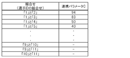
- FIG. 10 shows the storage contents of the parameter table.
- the parameter table is data in which a combination of IDs of two player objects 44 is associated with a linkage parameter C.
- the cooperation parameter C is data obtained by quantifying the degree of cooperation between the two player objects 44, and corresponds to a parameter related to the relationship between the two player objects 44.
- the parameter table is set so that the value of the cooperation parameter C increases as the cooperation between the two player objects 44 increases.
- the parameter condition table is stored in the optical disc 32.
- FIG. 11 shows the stored contents of the parameter condition table.
- the parameter condition table is data in which the parameter condition related to the linkage parameter C is associated with the size data for controlling the size of the determination area 51.
- the value of the radius Rj of the determination area 51 is stored as size data.
- the parameter condition table is set so that the value of the radius Rj increases as the value of the cooperation parameter C increases.
- the designated position acquisition unit 64 (designated position acquisition means) is realized mainly by the microprocessor 13, the controller interface 20, and the operation input unit 21.
- the designated position acquisition unit 64 acquires a position on the game screen designated by the user.
- the indicated position acquisition unit 64 acquires the screen coordinate value of the position P indicated by the front end 22a of the controller 22 based on the operation signal transmitted from the controller 22 at regular intervals. Then, the indication position acquisition unit 64 acquires the indication area of the cursor 52 based on the position P indicated by the front end portion 22a of the controller 22.
- FIG. 12 is a diagram for explaining an instruction area of the cursor 52. As shown in FIG. 12, the pointing area 53 of the cursor 52 is a circular area having a radius Rc centered on the position P indicated by the front end 22 a of the controller 22. The indication area 53 of the cursor 52 coincides with the area where the cursor 52 is displayed.
- the instruction area 53 of the cursor 52 corresponds to a position group (a set of positions) on the game screen specified by the user. That is, each position in the instruction area 53 of the cursor 52 corresponds to a position on the game screen instructed by the user.
- the radius Rc of the pointing area 53 of the cursor 52 is a fixed value.
- the instruction area 53 of the cursor 52 is simply referred to as “instruction area 53”.
- the game control unit 66 is realized mainly by the microprocessor 13, for example.
- the game control unit 66 includes a determination area control unit 68, a determination unit 70, and a designation unit 72 as functions related to the present invention.
- the determination unit 70 determines whether any player object 44 (selection candidate image) is instructed by the user. That is, the determination unit 70 determines whether or not the position (instruction region 53) acquired by the instruction position acquisition unit 64 is included in the determination region 51 corresponding to any player object 44 (selection candidate image). . Details of the operation of the determination unit 70 will be described later (see S103 in FIG. 13).
- the designation unit 72 indicates that the position (instruction area 53) acquired by the indicated position acquisition unit 64 is any of the player objects 44.
- the player object 44 selected candidate image
- the player object 44 is selected as the selected player object (selected image). Is specified. Details of the operation of the designation unit 72 will be described later (see S104 in FIG. 13).
- the determination area control unit 68 determines corresponding to another player object 44 (selection candidate image).
- the size of the area 51 is stored in the parameter table in association with the combination of the player object 44 (selection candidate image) designated as the selected player object (selection image) and the other player object 44 (selection candidate image). Change based on the linkage parameter C. Details of the operation of the determination area control unit 68 will be described later (see S105 in FIG. 13).
- FIG. 13 and FIG. 14 are flowcharts showing an example of processing executed by the game apparatus 10. 13 and 14 are executed by the microprocessor 13 operating according to a program.
- the process shown in FIG. 13 is a process executed when the value of the selection flag of all the player objects 44 belonging to the operation target team is “0”. That is, the process shown in FIG. 13 is a process executed at regular intervals when no player object 44 belonging to the operation target team is selected as the operation target.
- the microprocessor 13 acquires the instruction area 53 (S101).
- the microprocessor 13 acquires the position P on the game screen indicated by the front end 22a of the controller 22 based on the operation signal supplied from the controller 22. Then, the microprocessor 13 acquires a circular area having a radius Rc centered on the acquired position P as the instruction area 53.
- the microprocessor 13 determines whether or not the selection button has been pressed based on the operation signal supplied from the controller 22 (S102). If the selection button has not been pressed (N in S102), the microprocessor 13 ends the process.
- the microprocessor 13 determines whether any of the player objects 44 belonging to the operation target team is indicated by the front end 22a of the controller 22. Is determined (S103). That is, the microprocessor 13 determines, for each player object 44, whether or not the player object 44 is indicated by the front end portion 22a of the controller 22.
- the microprocessor 13 when determining whether or not the player object X is pointed by the front end 22a of the controller 22, the microprocessor 13 refers to the game situation data (particularly, the position field and the determination area field), and the player object X The determination area 51 corresponding to is specified. Note that the size (radius Rj) of the determination area 51 corresponding to the player object X at this time is set to a predetermined initial value. Then, the microprocessor 13 determines whether or not at least a part of the instruction area 53 is included in the determination area 51 corresponding to the player object X. When at least a part of the instruction area 53 is included in the determination area 51 corresponding to the player object X, it is determined that the player object X is indicated by the front end 22 a of the controller 22.
- the microprocessor 13 ends the process.
- the microprocessor 13 (designating means) is indicated by the front end 22a of the controller 22.
- the value of the selection flag of the player object 44 shown is set to “1” (S104). In this case, the value of the selection flag of the other player object 44 is set to “0”.
- the microprocessor 13 determines the determination area corresponding to the other player object 44 belonging to the operation target team.
- the size of 51 is changed (S105). That is, the size of the determination area 51 corresponding to the player object 44 whose selection flag value is set to “0” among the player objects 44 belonging to the operation target team is changed.
- the microprocessor 13 acquires the linkage parameter C associated with the combination of the player object X and the player object Y from the parameter table. Thereafter, the microprocessor 13 refers to the parameter condition table and identifies a parameter condition that satisfies the acquired linkage parameter C. Then, the microprocessor 13 updates the value of the radius Rj stored in the determination area field (see FIG. 9) of the player object Y based on the size data associated with the parameter condition.
- the process shown in FIG. 14 is a process executed when the value of the selection flag of any player object 44 belonging to the operation target team is “1”. That is, the process shown in FIG. 14 is executed at regular intervals when any player object 44 belonging to the operation target team is selected as the operation target.
- the microprocessor 13 acquires the instruction area 53 in the same manner as the step of S101 in FIG. 13 (S201).
- the microprocessor 13 determines whether or not the path instruction button is pressed based on the operation signal supplied from the controller 22 (S202).
- the microprocessor 13 determines whether or not the player object 44 whose selection flag is “1” holds the ball object 42 (S203). When the player object 44 whose selection flag is “1” does not hold the ball object 42 (N in S203), the microprocessor 13 ends the process.
- the microprocessor 13 determines that any of the other player objects 44 belonging to the operation target team is the controller 22. It is determined whether or not it is indicated by the front end portion 22a. That is, the microprocessor 13 determines whether any of the player objects 44 whose selection flag is “0” is indicated by the front end 22a of the controller 22 (S204). More specifically, the microprocessor 13 determines, for each player object 44 whose selection flag is “0”, whether or not the player object 44 is indicated by the front end portion 22 a of the controller 22.
- the microprocessor 13 determines whether or not the player object X is pointed by the front end portion 22a of the controller 22, a determination region in which at least a part of the instruction region 53 corresponds to the player object X 51 is determined.
- the determination area 51 corresponding to the player object X is specified by the content of the determination area field (see FIG. 9) after the change in step S105 of FIG.
- the instruction area 53 is included in the determination area 51 corresponding to the player object X, it is determined that the player object X is indicated by the front end 22 a of the controller 22.
- the microprocessor 13 ends the processing. On the other hand, when any of the player objects 44 whose selection flag is “0” is indicated by the front end 22a of the controller 22 (Y in S204), the microprocessor 13 is indicated by the front end 22a of the controller 22. A pass to the player object 44 being executed is executed (S205).
- the microprocessor 13 determines whether or not a selection cancel button (for example, the button 37a) has been pressed (S206). If the selection cancel button has not been pressed (N in S206), the microprocessor 13 ends the process. On the other hand, when the selection cancel button is pressed (Y in S206), the microprocessor 13 sets the value of the selection flag of the player object 44 whose selection flag is “1” to “0” (S207). By the step of S207, all the player objects 44 belonging to the operation target team are no longer operation targets. Further, the microprocessor 13 initializes the size of the determination area 51 for all the player objects 44 belonging to the operation target team (S208). Specifically, the value (radius Rj) of the determination area field is updated to a predetermined initial value for all player objects 44.
- a selection cancel button for example, the button 37a
- the ease of selecting a pass partner when selecting another player object 44 as a pass partner of the player object 44 holding the ball object 42 is as follows. It changes in accordance with the combination of the player object 44 holding the ball object 42 and another player object 44 that is a candidate for the pass opponent.
- the relationship between the player object 44 holding the ball object 42 and another player object 44 that is a candidate for a pass partner (for example, compatibility or cooperation is good or bad). ) Can be realized by the user.
- the ease of selection when the other player object 44 is selected as the pass partner or the like is selected. It has been changed by changing the size of the determination area 51 corresponding to the player object 44.
- the second embodiment is characterized in that, instead of changing the size of the determination area 51, the size of the instruction area 53 of the cursor 52 is changed. That is, in the second embodiment, the ease of selecting another player object 44 when any one of the player objects 44 belonging to the operation target team is selected as the operation target is the size of the instruction area 53 (radius Rc). It is characterized in that it can be changed by changing.
- Embodiment 2 will be described. Note that the hardware configuration of the game apparatus 10 according to the second embodiment is the same as that of the first embodiment (see FIGS. 1 to 3), and thus description thereof is omitted here. Also, in the game device 10 according to the second embodiment, for example, a soccer game is executed.
- FIG. 15 is a functional block diagram showing a function group realized in the game apparatus 10.
- a display control unit 60 a game data storage unit 62a, an instruction area acquisition unit 64a, and a game control unit 66a are realized. These functions are realized by the microprocessor 13 operating according to a program read from the optical disc 32.
- the function of the display control part 60 is the same as that of Embodiment 1, description is abbreviate
- the game data storage unit 62a stores game situation data, a parameter table, and a parameter condition table, similarly to the game data storage unit 62 in the first embodiment.
- the parameter condition table is different from that of the first embodiment, the parameter condition table will be described here.
- FIG. 16 shows an example of the parameter condition table in the second embodiment.
- the parameter condition table shown in the figure is data in which the parameter condition related to the linkage parameter C is associated with the size data for controlling the size of the instruction area 53. That is, in the parameter condition table in the second embodiment, size data for controlling the size of the instruction area 53 is stored, not size data for controlling the size of the determination area 51 (see FIG. 11).
- the value of the radius Rc of the indication area 53 is stored.
- the parameter condition table is set so that the value of the radius Rc increases as the value of the linkage parameter C increases.
- the game data storage unit 62a in the second embodiment stores instruction area data regarding the current size of the instruction area 53.
- the size of the indication area 53 is the size of the area of the indication area 53 when the indication area 53 is a two-dimensional area, and the indication area when the indication area 53 is a three-dimensional area. 53 volume size.
- the indication area data is data indicating the current value of the radius Rc of the indication area 53.
- the instruction area data is data indicating the length of each side of the instruction area 53 (rectangular area).
- the instruction area acquisition unit 64a (instruction area acquisition means) is realized mainly by the microprocessor 13, the controller interface 20, and the operation input unit 21.
- the instruction area acquisition unit 64a acquires an area on the game screen instructed by the user. In the case of this embodiment, the instruction area acquisition unit 64 a acquires the instruction area 53.
- the instruction area 53 is an area that coincides with an area where the cursor 52 is displayed. Details of the operation of the instruction area acquisition unit 64a will be described later (see S301 in FIG. 17).
- the game control unit 66a in the second embodiment includes a determination unit 70a, a designation unit 72a, a specifying unit 80, and an instruction area control unit 82.
- the determination unit 70a determines whether or not the instruction region 53 acquired by the instruction region acquisition unit 64a is included in the determination region 51 corresponding to any player object 44 (selection candidate image). Details of the operation of the determination unit 70a will be described later (see S303 in FIG. 17).
- the designation section 72a When it is determined that the instruction area 53 acquired by the instruction area acquisition section 64a is included in the determination area 51 corresponding to any player object 44 (selection candidate image), the designation section 72a The selection candidate image) is designated as the selected player object (selected image). Details of the operation of the designation unit 72a will be described later (see S304 in FIG. 17).
- the specifying unit 80 is assigned to another player object belonging to the operation target team.
- 44 selection candidate images
- the player object 44 selection candidate image having the shortest distance from the instruction area 53 is specified. Details of the operation of the specifying unit 80 will be described later (see S401 in FIG. 18).
- the instruction area control unit 82 associates with the combination of the player object 44 (selection candidate image) specified as the selected player object (selection image) and the player object 44 (selection candidate image) specified by the specifying unit 80.
- the size of the instruction area 53 is changed based on the parameters stored in the parameter table. Details of the operation of the instruction area control unit 82 will be described later (see S402 in FIG. 18).
- FIG. 17 and 18 are flowcharts showing an example of processing executed by the game device 10 according to the second embodiment. 17 and 18 are executed by the microprocessor 13 operating according to a program.
- the process shown in FIG. 17 corresponds to the process shown in FIG. 13 in the first embodiment. That is, the process shown in FIG. 17 is a process executed when the value of the selection flag of all the player objects 44 belonging to the operation target team is “0”. That is, the process shown in FIG. 17 is a process executed at regular intervals when no player object 44 belonging to the operation target team is selected as the operation target.
- the microprocessor 13 acquires the instruction area 53 (S301).
- step S ⁇ b> 301 the microprocessor 13 acquires a position P on the game screen indicated by the front end 22 a of the controller 22 based on the operation signal supplied from the controller 22. Thereafter, the microprocessor 13 refers to the instruction area data and acquires the radius Rc of the current instruction area 53. At this time, the size (radius Rc) of the instruction area 53 is set to a predetermined initial value. Then, the microprocessor 13 acquires a circular area having a radius Rc centered on the position P as the indication area 53.
- the microprocessor 13 determines whether or not the selection button has been pressed based on the operation signal supplied from the controller 22 (S302). If the selection button has not been pressed (N in S302), the microprocessor 13 ends the process.
- the microprocessor 13 determines whether any of the player objects 44 belonging to the operation target team is pointed to by the front end portion 22a of the controller 22 ( S303). The process in this step is the same as the process in step S103 in FIG.
- the microprocessor 13 ends the process.
- the microprocessor 13 (designating means) is indicated by the front end 22a of the controller 22.
- the value of the selection flag of the player object 44 shown is set to “1” (S304). The process in this step is the same as the process in step S104 in FIG.
- the process shown in FIG. 18 corresponds to the process shown in FIG. 14 in the first embodiment. That is, the process shown in FIG. 18 is a process executed when the value of the selection flag of any player object 44 belonging to the operation target team is “1”. That is, the process shown in FIG. 18 is executed at regular intervals when any player object 44 belonging to the operation target team is selected as the operation target.
- the player object 44 having a selection flag value of “1”, that is, the player object 44 in a state selected as an operation target is referred to as “player object X”.
- the microprocessor 13 specifies the player object 44 having the shortest distance from the instruction area 53 among the player objects 44 other than the player object X among the player objects 44 belonging to the operation target team (S401). That is, the microprocessor 13 (specifying means) specifies the player object 44 that belongs to the operation target team and has the shortest distance from the instruction area 53 among the player objects 44 whose selection flag value is “0”. To do.
- step S401 the microprocessor 13 relates to each of the player objects 44 whose selection flag value is “0”, that is, the position P on the game screen indicated by the center point of the instruction area 53 (ie, the front end 22a of the controller 22). ) To the display position of the player object 44 is acquired.
- the “display position of the player object 44” is obtained by converting the world coordinate value of the representative point of the player object 44 (the coordinate value of the XW-YW-ZW coordinate system in FIG. 4) into a screen coordinate value by a predetermined coordinate conversion calculation. Is obtained by And the player object 44 with the shortest distance from the instruction
- the player object 44 identified in step S401 is referred to as “player object Y”.
- the microprocessor 13 changes the size of the instruction area 53 (S402).
- the microprocessor 13 acquires the linkage parameter C associated with the combination of the player object X and the player object Y from the parameter table. Thereafter, the microprocessor 13 refers to the parameter condition table and identifies a parameter condition that satisfies the acquired linkage parameter C. Then, the microprocessor 13 updates the instruction area data (the value of the radius Rc of the instruction area 53) based on the size data associated with the parameter condition.
- the microprocessor 13 acquires the designated area 53 in the same manner as in step S301 in FIG. 17 (S403). After the instruction area 53 is acquired, the microprocessor 13 executes the processes of S202 to S208 shown in FIG. 14 as in the first embodiment. However, in the second embodiment, in step S208, instead of initializing the size of the determination area 51, the size of the instruction area 53 is initialized. That is, the instruction area data is initialized, and the radius Rc of the instruction area 53 is set to a predetermined initial value.
- the size of the instruction area 53 when the other player object 44 is selected as the pass partner of the player object 44 holding the ball object 42 is the ball object 42. Is changed in accordance with the combination of the player object 44 holding the character and another player object 44 that is a candidate of the pass partner.
- the linkage parameter C corresponding to the combination of the player object 44 holding the ball object 42 and another player object 44 that is a candidate for a pass partner is high, the size of the instruction area 53 is increased. . In this case, the user can easily select the player object 44 as a pass partner.
- the linkage parameter C corresponding to the combination of the player object 44 holding the ball object 42 and another player object 44 that is a candidate for a pass partner is low, the size of the instruction area 53 is small. . In this case, it becomes difficult for the user to select the player object 44 as a pass partner.
- the ease of selecting a pass opponent is determined by the player object 44 holding the ball object 42 and the other player objects 44 that are candidates for the pass opponent. It changes according to the combination.
- the relationship between the player object 44 holding the ball object 42 and another player object 44 that is a candidate for the pass opponent (for example, whether compatibility or cooperation is good or bad). It is possible to make the user feel it.
- FIG. 19 is a functional block diagram showing a functional group realized by the game apparatus 10 in this modified example.
- a display control unit 60 in the game apparatus 10 in this case, a display control unit 60, a game data storage unit 62b, an instruction area acquisition unit 64a, and a game control unit 66b are realized.
- the display control unit 60 is the same as that of the first and second embodiments, and the instruction area acquisition unit 64a is the same as that of the second embodiment.
- the game data storage unit 62b stores data stored in the game data storage unit 62 (see FIG. 8) and the game data storage unit 62a (see FIG. 15). For example, both the parameter condition table shown in FIG. 12 and the parameter condition table shown in FIG. 16 are stored in the game data storage unit 62b.
- the game control unit 66b includes a determination region control unit 68, a determination unit 70a, a designation unit 72a, a specifying unit 80, and an instruction region control unit 82.
- the determination area control unit 68 is the same as that of the first embodiment, and the determination unit 70a, the designation unit 72a, the specifying unit 80, and the instruction area control unit 82 are the same as those of the second embodiment.
- step S101 the microprocessor 13 acquires the instruction area 53 based on the operation signal supplied from the controller 22 and the instruction area data stored in the game data storage unit 62b.
- the microprocessor 13 determineation area control means, first changing means
- the microprocessor 13 is in a state in which any of the player objects 44 belonging to the operation target team is selected as the operation target in the first embodiment or the first modification.
- the size of the determination area 51 corresponding to the other player object 44 may be changed according to the elapsed time from the reference timing.
- the microprocessor 13 is based on the linkage parameter C stored in the parameter table in association with the combination of the player object 44 that is selected as the operation target and the other player object 44. You may make it control the aspect to which the size of the determination area
- the parameter condition table shown in FIG. is data in which a parameter condition that is a condition relating to the linkage parameter C is associated with size data that is data for controlling a change in the size (radius Rj) of the determination region 51.
- RJ1 to RJ5 indicate the initial size of the determination area 51
- ⁇ RJ1 to ⁇ RJ5 indicate the amount of change in the size of the determination area 51 per unit time, that is, the enlargement speed of the determination area 51. Yes.
- the parameter condition table shown in FIG. 20 is set so that the initial sizes RJ1 to RJ5 of the determination area 51 become larger as the value of the linkage parameter C is larger. Further, the enlargement speeds ⁇ RJ1 to ⁇ RJ5 of the determination area 51 are set to increase as the value of the cooperation parameter C increases. That is, in the parameter condition table, the mode of change in the size of the determination area 51 (enlargement speed) changes according to the value of the linkage parameter C.
- the microprocessor 13 executes the processing shown in FIG.
- step S105 the microprocessor 13 changes the size of the determination area 51 as described below.
- step S105 in Example 2 will be described.
- the microprocessor 13 also executes the process shown in FIG. 14 in the second modification.
- the elapsed time T after any player object 44 is selected as the operation target is stored in the main memory 14. Further, the microprocessor 13 executes the same process as the process of step S105 before executing the process of step S201. Corresponding to the combination of the player object 44 that is selected as the operation target and the other player objects 44 belonging to the operation target team by executing the process of step S105 before the process of step S201. The size of the determination area 51 corresponding to the other player object 44 is changed in a mode (enlargement speed) based on the attached cooperation parameter C.
- the speed of enlargement of the size of the determination area 51 corresponding to the player object Y belonging to the operation target team is It changes according to the relationship with the player object Y (for example, compatibility or cooperation is good or bad).
- the ease of selection of the player object Y changes according to the relationship between the player object X and the player object Y.
- the initial sizes RJ1 to RJ5 of the determination area 51 may be constant values regardless of the value of the linkage parameter C.
- the enlargement speeds ⁇ RJ1 to ⁇ RJ5 of the determination area 51 may be set to a constant value regardless of the value of the linkage parameter C.
- the size (initial size) of the determination area 51 before changing the size of the determination area 51 according to the elapsed time T is related to the relationship between the player object X and the player object Y (for example, whether compatibility or cooperation is good or bad). It will change accordingly.
- the microprocessor 13 (instruction area control means, second changing means) is in a state in which any of the player objects 44 belonging to the operation target team is selected as the operation target in the second embodiment or the first modification.
- the size of the instruction area 53 may be changed according to the elapsed time from the reference timing.
- the microprocessor 13 is based on the linkage parameter C stored in the parameter table in association with the combination of the player object 44 that is selected as the operation target and the other player object 44. You may make it control the aspect which changes the size of the instruction
- the parameter condition table shown in FIG. is data in which a parameter condition that is a condition relating to the linkage parameter C is associated with size data that is data for controlling a change in the size (radius Rc) of the instruction area 53.
- RC1 to RC5 indicate the initial size of the instruction area 53
- ⁇ RC1 to ⁇ RC5 indicate the amount of change in the size of the instruction area 53 per unit time, that is, the enlargement speed of the instruction area 53. Yes.
- the parameter condition table shown in FIG. 21 is set so that the initial sizes RC1 to RC5 of the instruction area 53 become larger as the value of the linkage parameter C is larger. Further, the enlargement speeds ⁇ RC1 to ⁇ RC5 of the instruction area 53 are set to increase as the value of the cooperation parameter C increases. That is, in the parameter condition table, the change mode (enlargement speed) of the size of the instruction area 53 changes according to the value of the linkage parameter C.
- the microprocessor 13 executes the processing shown in FIG. 13 or FIG.
- the microprocessor 13 when any player object 44 belonging to the operation target team is selected as the operation target, the microprocessor 13 also executes the process shown in FIG. 18 in the third modification.
- the microprocessor 13 changes the size of the instruction area 53 as described below.
- the case where the player object 44 selected as the operation target is the player object X and the player object 44 specified in the process of step S401 is the player object Y is an example of S402 in the third modification. Step processing will be described.
- the microprocessor 13 acquires the linkage parameter C associated with the combination of the player object X and the player object Y from the parameter table. Thereafter, the microprocessor 13 refers to the parameter condition table and identifies a parameter condition that satisfies the acquired linkage parameter C. Then, the microprocessor 13 updates the instruction area data (the value of the radius Rc of the instruction area 53) based on the size data associated with the parameter condition and the elapsed time T.
- step S402 the cooperation parameter C associated with the combination of the player object 44 selected as the operation target and the other player object 44 belonging to the operation target team is set.
- the size of the instruction area 53 is changed in a mode (enlargement speed) based on the above.
- the speed of enlargement of the size of the instruction area 53 is the relationship between the player object X and the player object Y (for example, compatibility or cooperation It changes according to the good or bad).
- the ease of selection of the player object Y changes according to the relationship between the player object X and the player object Y.
- the initial sizes RC1 to RC5 of the instruction area 53 may be set to a constant value regardless of the value of the linkage parameter C.
- the enlargement speeds ⁇ RC1 to ⁇ RC5 of the instruction area 53 may be constant values regardless of the value of the linkage parameter C.
- the size (initial size) of the instruction area 53 before changing the size of the instruction area 53 according to the elapsed time T is related to the relationship between the player object X and the player object Y (for example, whether compatibility or cooperation is good or bad). It will change accordingly. Even if it does in this way, since the ease of selection of the player object Y changes according to the relationship between the player object X and the player object Y (e.g., compatibility or good or bad), the user can feel the relationship between the player object X and the player object Y. It becomes possible to make it.
- the size of the determination area 51 corresponding to the player object 44 may be changed based on the moving direction or / and moving speed of the player object 44.
- the determination area 51 corresponding to the player object 44 may be extended in the moving direction of the player object 44.
- the degree of expansion of the determination area 51 of the player object 44 may be controlled based on the moving speed of the player object 44.
- the extent of extension of the determination area 51 may be increased as the moving speed of the player object 44 increases.
- the determination area 51 corresponding to the player object 44 may be enlarged based on the moving speed of the player object 44. More specifically, the degree of expansion of the determination area 51 corresponding to the player object 44 may be controlled based on the moving speed of the player object 44. For example, the degree of enlargement of the determination area 51 may be increased as the moving speed of the player object 44 increases.
- the determination area control unit 68 is selected as the operation target. You may make it change the size of the determination area
- the determination region control unit 68 is selected as the operation target. You may make it change the size of the determination area
- the interface for the user to specify the position in the game screen is not limited to the interface described above.
- the microprocessor 13 may move the cursor 52 in the direction designated by the user using the direction button 36.
- the pointing position acquisition unit 64 and the pointing region acquisition unit 64a use the center position of the cursor 52 instead of the position P indicated by the front end 22a of the controller 22.
- the interface for the user to specify the position in the game screen may be a touch panel installed on the monitor 30 (for example, a liquid crystal monitor).
- the instruction position acquisition unit 64 and the instruction region acquisition unit 64a use the position in the game screen pressed by the user instead of the position P indicated by the front end 22a of the controller 22.
- the present invention is also applicable when a game other than a sports game is provided on the game apparatus 10.
- the present invention can also be applied to the case where the game device 10 provides an action game in which a plurality of characters (selection candidate images) are displayed on the game screen.
- selection candidate images For example, when the user selects the first character as the operation target and then selects the second character by directing the front end 22a of the controller 22 toward the second character, the first character magically acts on the second character.
- the present invention can also be applied to the case where a game that applies a game is provided in the game apparatus 10.
Landscapes
- Engineering & Computer Science (AREA)
- Multimedia (AREA)
- Human Computer Interaction (AREA)
- Theoretical Computer Science (AREA)
- Processing Or Creating Images (AREA)
- User Interface Of Digital Computer (AREA)
Abstract
ユーザがいずれかの選択候補画像を選択する操作を行う場合に、他の選択候補画像との関係をユーザに実感させることが可能なゲーム装置を提供する。 判定手段(70a)は、ユーザによって指示された指示領域が、選択候補画像に対応する判定領域に含まれるか否かを判定する。指定手段(72a)は、指示領域が判定領域に含まれる場合、当該判定領域に対応する選択候補画像を選択画像に指定する。判定領域制御手段(68)は、選択画像に指定された選択候補画像と、他の選択候補画像と、の組合せに対応付けて記憶されるパラメータに基づいて、当該他の選択候補画像に対応する判定領域のサイズを変化させる。指示領域制御手段(82)は、選択画像に指定された選択候補画像と、指示領域からの距離が最も短い選択候補画像と、の組合せに対応付けて記憶されるパラメータに基づいて、指示領域のサイズを変化させる。
Description
本発明は、ゲーム装置、ゲーム装置の制御方法、プログラム、及び情報記憶媒体に関する。
複数の選択候補画像を表示手段に表示し、ユーザによって指示された指示位置(指示領域)がいずれかの選択候補画像に対応する判定領域に含まれる場合に当該選択候補画像を選択画像(ユーザによって選択された画像)に指定するゲーム装置が知られている。
例えば、複数のキャラクタを表示手段に表示し、ユーザによって指示された指示位置(指示領域)がいずれかのキャラクタ(選択候補画像)に対応する判定領域に含まれる場合に、該キャラクタが選択されたと判断し、該キャラクタに関連するゲーム処理を実行するゲーム装置が知られている。例えば、キャラクタがボールを保持している状態で該キャラクタと同じチームに属する他のキャラクタがユーザによって選択された場合に、ボールを保持しているキャラクタからユーザが選択したキャラクタへのパスを実行するサッカーゲーム装置が知られている。
例えば、実際のスポーツの試合では、選手同士の関係(例えば相性、又は連携の善し悪し)によって、選手間のパスが円滑に行われたり、行われなかったりする場合がある。
この点、従来のサッカーゲーム装置では、ユーザがあるキャラクタを指示する操作を行う場合に、他のキャラクタとの関係(例えば相性や連携の善し悪し)をユーザに実感させるという点で物足りない場合があった。特に、一人のユーザが複数のキャラクタを切り替えながら操作する場合、操作する人はあくまでも一人なので、キャラクタ間の関係(例えば相性や連携の善し悪し)をユーザに実感させることが難しかった。
本発明は、上記課題に鑑みてなされたものであって、ユーザがいずれかの選択候補画像を選択する操作を行う場合に、他の選択候補画像との関係をユーザに実感させることが可能なゲーム装置、ゲーム装置の制御方法、プログラム、及び情報記憶媒体の提供をその目的とする。
上記課題を解決するために、本発明に係るゲーム装置は、複数の選択候補画像を表示手段に表示する表示制御手段と、前記選択候補画像の組合せに対応付けてパラメータを記憶するパラメータ記憶手段と、ユーザによって指示された指示領域を取得する指示領域取得手段と、前記指示領域取得手段によって取得された指示領域が、前記選択候補画像に対応する判定領域に含まれるか否かを判定する判定手段と、前記指示領域取得手段によって取得された指示領域が前記判定領域に含まれる場合、当該判定領域に対応する選択候補画像を選択画像に指定する指定手段と、前記指定手段によって前記複数の選択候補画像のうちのいずれかが前記選択画像に指定された場合、前記複数の選択候補画像のうちの他の選択候補画像に対応する判定領域のサイズを、前記選択画像に指定された選択候補画像と、前記他の選択候補画像と、の組合せに対応付けて記憶されるパラメータに基づいて変化させる判定領域制御手段と、前記指定手段によって前記複数の選択候補画像のうちのいずれかが前記選択画像に指定された場合、前記複数の選択候補画像のうちの他の選択候補画像のうちで、前記指示領域からの距離が最も短い選択候補画像を特定する特定手段と、前記選択画像に指定された選択候補画像と、前記特定手段によって特定された選択候補画像と、の組合せに対応付けて記憶されるパラメータに基づいて、前記指示領域のサイズを変化させる指示領域制御手段と、を含むことを特徴とする。
また、本発明に係るゲーム装置の制御方法は、複数の選択候補画像を表示手段に表示する表示制御ステップと、前記選択候補画像の組合せに対応付けてパラメータを記憶してなるパラメータ記憶手段の記憶内容を読み出すステップと、ユーザによって指示された指示領域を取得する指示領域取得ステップと、前記指示領域取得ステップにおいて取得された指示領域が、前記選択候補画像に対応する判定領域に含まれるか否かを判定する判定ステップと、前記指示領域取得ステップにおいて取得された指示領域が前記判定領域に含まれる場合、当該判定領域に対応する選択候補画像を選択画像に指定する指定ステップと、前記指定ステップにおいて前記複数の選択候補画像のうちのいずれかが前記選択画像に指定された場合、前記複数の選択候補画像のうちの他の選択候補画像に対応する判定領域のサイズを、前記選択画像に指定された選択候補画像と、前記他の選択候補画像と、の組合せに対応付けて記憶されるパラメータに基づいて変化させる判定領域制御ステップと、前記指定ステップにおいて前記複数の選択候補画像のうちのいずれかが前記選択画像に指定された場合、前記複数の選択候補画像のうちの他の選択候補画像のうちで、前記指示領域からの距離が最も短い選択候補画像を特定する特定ステップと、前記選択画像に指定された選択候補画像と、前記特定ステップにおいて特定された選択候補画像と、の組合せに対応付けて記憶されるパラメータに基づいて、前記指示領域のサイズを変化させる指示領域制御ステップとを含むことを特徴とする。
また、本発明に係るプログラムは、ゲーム装置として家庭用ゲーム機、業務用ゲーム機、携帯ゲーム機、及び携帯情報端末などのコンピュータを機能させるプログラムであって、複数の選択候補画像を表示手段に表示する表示制御手段、前記選択候補画像の組合せに対応付けてパラメータを記憶してなるパラメータ記憶手段の記憶内容を読み出す手段、ユーザによって指示された指示領域を取得する指示領域取得手段、前記指示領域取得手段によって取得された指示領域が、前記選択候補画像に対応する判定領域に含まれるか否かを判定する判定手段、指示領域取得手段によって取得された指示領域が前記判定領域に含まれる場合、当該判定領域に対応する選択候補画像を選択画像に指定する指定手段、前記指定手段によって前記複数の選択候補画像のうちのいずれかが前記選択画像に指定された場合、前記複数の選択候補画像のうちの他の選択候補画像に対応する判定領域のサイズを、前記選択画像に指定された選択候補画像と、前記他の選択候補画像と、の組合せに対応付けて記憶されるパラメータに基づいて変化させる判定領域制御手段、前記指定手段によって前記複数の選択候補画像のうちのいずれかが前記選択画像に指定された場合、前記複数の選択候補画像のうちの他の選択候補画像のうちで、前記指示領域からの距離が最も短い選択候補画像を特定する特定手段、及び、前記選択画像に指定された選択候補画像と、前記特定手段によって特定された選択候補画像と、の組合せに対応付けて記憶されるパラメータに基づいて、前記指示領域のサイズを変化させる指示領域制御手段として前記コンピュータを機能させることを特徴とする。
また、本発明に係る情報記憶媒体は、上記プログラムを記録したコンピュータ読取可能な情報記憶媒体である。
本発明によれば、ユーザがいずれかの選択候補画像を選択する操作を行う場合に、他の選択候補画像との関係をユーザに実感させることが可能になる。
また、本発明の一態様では、前記判定領域制御手段は、前記他の選択候補画像に対応する判定領域のサイズを、基準タイミングからの経過時間に応じて変化させる第1変化手段と、前記他の選択候補画像に対応する判定領域のサイズを前記第1変化手段が変化させる前の当該判定領域のサイズ、又は、前記他の選択候補画像に対応する判定領域のサイズを前記第1変化手段が変化させる態様を、前記選択画像に指定された選択候補画像と、前記他の選択候補画像と、の組合せに対応付けて記憶される前記パラメータに基づいて制御する手段と、を含み、前記指示領域制御手段は、前記指示領域のサイズを、前記基準タイミングからの経過時間に応じて変化させる第2変化手段と、前記指示領域のサイズを前記第2変化手段が変化させる前の前記指示領域のサイズ、又は、前記指示領域のサイズを前記第2変化手段が変化させる態様を、前記選択画像に指定された選択候補画像と、前記特定手段によって特定された選択候補画像と、の組合せに対応付けて記憶される前記パラメータに基づいて制御する手段と、を含むようにしてもよい。
また、本発明に係るゲーム装置は、複数の選択候補画像を表示手段に表示する表示制御手段と、前記選択候補画像の組合せに対応付けてパラメータを記憶するパラメータ記憶手段と、ユーザによって指示された位置を取得する指示位置取得手段と、前記指示位置取得手段によって取得された位置が、前記選択候補画像に対応する判定領域に含まれるか否かを判定する判定手段と、前記指示位置取得手段によって取得された位置が前記判定領域に含まれる場合、当該判定領域に対応する選択候補画像を選択画像に指定する指定手段と、前記指定手段によって前記複数の選択候補画像のうちのいずれかが前記選択画像に指定された場合、前記複数の選択候補画像のうちの他の選択候補画像に対応する判定領域のサイズを、前記選択画像に指定された選択候補画像と、前記他の選択候補画像と、の組合せに対応付けて記憶されるパラメータに基づいて変化させる判定領域制御手段と、を含むことを特徴とする。
本発明によれば、ユーザがいずれかの選択候補画像を選択する操作を行う場合に、他の選択候補画像との関係をユーザに実感させることが可能になる。
また、本発明に係るゲーム装置は、複数の選択候補画像を表示手段に表示する表示制御手段と、前記選択候補画像の組合せに対応付けてパラメータを記憶するパラメータ記憶手段と、ユーザによって指示された指示領域を取得する指示領域取得手段と、前記指示領域取得手段によって取得された指示領域が、前記選択候補画像に対応する判定領域に含まれるか否かを判定する判定手段と、前記指示領域取得手段によって取得された指示領域が前記判定領域に含まれる場合、当該判定領域に対応する選択候補画像を選択画像に指定する指定手段と、前記指定手段によって前記複数の選択候補画像のうちのいずれかが前記選択画像に指定された場合、前記複数の選択候補画像のうちの他の選択候補画像のうちで、前記選択画像からの距離が最も短い選択候補画像を特定する特定手段と、前記選択画像に指定された選択候補画像と、前記特定手段によって特定された選択候補画像と、の組合せに対応付けて記憶されるパラメータに基づいて、前記指示領域のサイズを変化させる指示領域制御手段と、を含むことを特徴とする。
本発明によれば、ユーザがいずれかの選択候補画像を選択する操作を行う場合に、他の選択候補画像との関係をユーザに実感させることが可能になる。
[1.実施形態1]
以下、本発明の実施形態1について図面に基づき詳細に説明する。本発明の実施形態に係るゲーム装置は、例えば家庭用ゲーム機(据置型ゲーム機)、携帯ゲーム機、携帯電話機、携帯情報端末(PDA)又はパーソナルコンピュータ等によって実現される。ここでは、実施形態1に係るゲーム装置を家庭用ゲーム機によって実現する場合について説明する。
以下、本発明の実施形態1について図面に基づき詳細に説明する。本発明の実施形態に係るゲーム装置は、例えば家庭用ゲーム機(据置型ゲーム機)、携帯ゲーム機、携帯電話機、携帯情報端末(PDA)又はパーソナルコンピュータ等によって実現される。ここでは、実施形態1に係るゲーム装置を家庭用ゲーム機によって実現する場合について説明する。
[1-1.ゲーム装置のハードウェア構成]
図1は、実施形態1に係るゲーム装置のハードウェア構成を示す。図1に示すゲーム装置10は、家庭用ゲーム機11、モニタ30、スピーカ31、光ディスク32及びメモリカード33を含む。モニタ30及びスピーカ31は家庭用ゲーム機11に接続される。光ディスク32及びメモリカード33は情報記憶媒体であり、家庭用ゲーム機11に装着される。モニタ30としては例えば家庭用テレビ受像機が用いられる。スピーカ31としては例えば家庭用テレビ受像機に内蔵されたスピーカが用いられる。光ディスク32としては例えばCD-ROMやDVD-ROMなどが用いられる。
図1は、実施形態1に係るゲーム装置のハードウェア構成を示す。図1に示すゲーム装置10は、家庭用ゲーム機11、モニタ30、スピーカ31、光ディスク32及びメモリカード33を含む。モニタ30及びスピーカ31は家庭用ゲーム機11に接続される。光ディスク32及びメモリカード33は情報記憶媒体であり、家庭用ゲーム機11に装着される。モニタ30としては例えば家庭用テレビ受像機が用いられる。スピーカ31としては例えば家庭用テレビ受像機に内蔵されたスピーカが用いられる。光ディスク32としては例えばCD-ROMやDVD-ROMなどが用いられる。
家庭用ゲーム機11は公知のコンピュータゲームシステムである。家庭用ゲーム機11は、バス12、マイクロプロセッサ13、主記憶14、画像処理部15、音声処理部16、光ディスクドライブ17、メモリカードスロット18、通信インタフェース(I/F)19、コントローラインタフェース(I/F)20及び操作入力部21を含む。操作入力部21以外の構成要素は家庭用ゲーム機11の筐体内に収容される。
バス12はアドレス及びデータを家庭用ゲーム機11の各部でやり取りするための通信路である。マイクロプロセッサ13、主記憶14、画像処理部15、音声処理部16、光ディスクドライブ17、メモリカードスロット18、通信インタフェース19及びコントローラインタフェース20は、バス12によって相互データ通信可能に接続される。
マイクロプロセッサ13は、図示しないROMに格納されるオペレーティングシステムや、光ディスク32又はメモリカード33から読み出されるプログラム及びデータに基づいて、家庭用ゲーム機11の各部を制御する。主記憶14は例えばRAMを含み、光ディスク32又はメモリカード33から読み出されたプログラム及びデータが必要に応じて書き込まれる。主記憶14はマイクロプロセッサ13の作業用としても用いられる。
画像処理部15はVRAMを含み、マイクロプロセッサ13から送られる画像データに基づいてVRAM上にゲーム画面を描画する。そして画像処理部15は、そのゲーム画面をビデオ信号に変換して所定のタイミングでモニタ30に出力する。音声処理部16はサウンドバッファを含む。音声処理部16は、光ディスク32からサウンドバッファに読み出された音声データを再生することにより、各種ゲーム音声(ゲーム音楽、ゲーム効果音、メッセージ等)をスピーカ31から出力する。
光ディスクドライブ17は、光ディスク32に記録されたプログラムやデータをマイクロプロセッサ13からの指示に従って読み取る。ここではプログラムやデータを家庭用ゲーム機11に供給するために光ディスク32を用いることとするが、例えばメモリカード33などの他のあらゆる情報記憶媒体を用いるようにしてもよい。また、インターネットなどのデータ通信網を介して遠隔地からプログラムやデータを家庭用ゲーム機11に供給するようにしてもよい。
メモリカードスロット18はメモリカード33を装着するためのインタフェースである。メモリカード33は不揮発性メモリ(例えばEEPROMなど)を含み、例えばセーブデータなどの各種ゲームデータを記憶する。通信インタフェース19は、インターネットなどのデータ通信網に通信接続するためのインタフェースである。
コントローラインタフェース20は複数のコントローラ22を無線接続するためのインタフェースである。コントローラインタフェース20としては、例えばBluetooth(登録商標)インタフェース規格に則ったインタフェースを利用できる。なお、コントローラインタフェース20はコントローラ22を有線接続するためのインタフェースとしてもよい。
操作入力部21はユーザが操作入力を行うためのものである。操作入力部21は、例えば、モニタ30に表示されるゲーム画面内の位置をユーザが指し示すためのポインティングデバイスとしての機能を備える。操作入力部21としては、例えば特許3262677号公報に開示される技術を利用できる。操作入力部21は、コントローラ22と、発光部25と、を含む。図2は操作入力部21の一例を示し、図3はコントローラ22の一例を示す。
図2に示すように、発光部25は複数の光源を含み、モニタ30の上部に配置される。図2に示す例では、発光部25の両端部に光源34a,34bが設けられている。なお、発光部25はモニタ30の下部に配置されるようにしてもよい。
図3に示すように、コントローラ22は方向ボタン36、ボタン37a,37b,37cを含む。方向ボタン36は十字形状を有し、一般的に方向指示操作に用いられる。ボタン37a,37b,37cは各種ゲーム操作に用いられる。また図1に示すように、コントローラ22は撮像部23と撮影画像解析部24とを含む。撮像部23は例えばCCDなどの撮像素子であり、コントローラ22の前端部22aに設けられる。撮影画像解析部24は例えばマイクロプロセッサなどであり、コントローラ22に内蔵される。
ユーザがコントローラ22の前端部22aをモニタ30の方に向けると、撮像部23の撮影画像には光源34a,34bが写し出される。撮影画像解析部24は、撮像部23の撮影画像に写し出された光源34a,34bの位置を解析し、その解析結果に基づいてコントローラ22の位置及び傾きを取得する。例えば、撮影画像解析部24は、所定の基準位置35に対するコントローラ22の相対位置と、光源34a及び光源34bを結ぶ直線に対するコントローラ22の傾き角度と、を算出する。ゲーム装置10は、基準位置35と、モニタ30に表示されるゲーム画面と、の位置関係に関する情報を記憶しており、この情報と、撮影画像解析部24によって取得されるコントローラ22の位置及び傾きに基づいて、コントローラ22の前端部22aが指し示す位置Pのスクリーン座標値(スクリーン座標系の座標値)を取得する。
なお、撮影画像解析部24によって取得されるコントローラ22の位置及び傾きを示す情報、すなわち、コントローラ22の前端部22aが指し示す位置Pのスクリーン座標値を特定するための情報のことを「ポインティング情報」と記載する。
コントローラ22からマイクロプロセッサ13に対しては、一定周期ごと(例えば1/60秒ごと)にコントローラ22の操作状態を表す操作信号がコントローラインタフェース20を介して送信される。この操作信号には、例えば、上記のポインティング情報と、各ボタンの押下状態を示す情報と、が含まれる。マイクロプロセッサ13は、コントローラ22から供給される操作信号に基づいて、コントローラ22の前端部22aが指し示す位置Pを特定したり、そのコントローラ22において方向ボタン36、ボタン37a,37b,37cが押下されたか否かを判定したりする。
[1-2.ゲーム装置で実行されるゲーム]
上記ゲーム装置10では、例えば、ユーザの操作対象チームと、対戦相手チームと、がサッカーの試合を行うサッカーゲームが実行される。このサッカーゲームは、光ディスク32から読み出されたプログラムが実行されることによって実現される。
上記ゲーム装置10では、例えば、ユーザの操作対象チームと、対戦相手チームと、がサッカーの試合を行うサッカーゲームが実行される。このサッカーゲームは、光ディスク32から読み出されたプログラムが実行されることによって実現される。
ゲーム装置10の主記憶14には仮想3次元空間が構築される。図4は、仮想3次元空間の一例を示している。図4に示すように、仮想3次元空間には、互いに直交するXw軸、Yw軸、及びZw軸が設定される。仮想3次元空間内の位置は、これらの座標軸のワールド座標値(ワールド座標系の座標値)により特定される。また、仮想3次元空間には、サッカーフィールドを表すフィールドオブジェクト38が配置される。フィールドオブジェクト38は、例えば、Xw-Zw平面に平行に配置される。
フィールドオブジェクト38上には、以下のオブジェクトが配置される。
(1)サッカーボール(移動物体)を表すボールオブジェクト42
(2)2つのゴールオブジェクト40
(3)11体の選手オブジェクト44と11体の選手オブジェクト46
(1)サッカーボール(移動物体)を表すボールオブジェクト42
(2)2つのゴールオブジェクト40
(3)11体の選手オブジェクト44と11体の選手オブジェクト46
ボールオブジェクト42は、仮想3次元空間内を移動する。また、ボールオブジェクト42は、いずれかの選手オブジェクト44(46)に近づくとその選手オブジェクト44(46)に関連付けられる。選手オブジェクト44(46)にボールオブジェクト42が関連付けられた場合、その選手オブジェクト44(46)はボールオブジェクト42を保持している状態になる。選手オブジェクト44(46)にボールオブジェクト42に関連付けられた場合、ボールオブジェクト42はその選手オブジェクト44(46)の移動に従って移動する。
一方のゴールオブジェクト40は操作対象チームに関連づけられ、他方のゴールオブジェクト40は対戦相手チームに関連づけられている。一方のチームに関連づけられたゴールオブジェクト40内の領域にボールオブジェクト42が移動した場合、他方のチームの得点イベントが発生する。なお、以下では、図4の右側のゴールオブジェクト40が操作対象チームに関連づけられ、図4の左側のゴールオブジェクト40が対戦相手チームに関連づけられていることとして説明する。
選手オブジェクト44は操作対象チームに属するサッカー選手を表し、選手オブジェクト46は対戦相手チームに属するサッカー選手を表す。なお、図4は、選手オブジェクト44と、選手オブジェクト46と、を1体ずつ示している。
仮想3次元空間には仮想カメラ48(視点及び視線方向)が設定される。仮想カメラ48は、例えばボールオブジェクト42に移動に従って移動する。仮想カメラ48から仮想3次元空間を見た様子を示すゲーム画面がモニタ30(表示手段)に表示される。
図5は、ゲーム画面の一例を示している。図5に示すゲーム画面には、ボールオブジェクト42と、操作対象チームに属する3体の選手オブジェクト44a,44b,44cと、対戦相手チームに属する1体の選手オブジェクト46とが表示されている。図5に示すゲーム画面では、ボールオブジェクト42が選手オブジェクト44aに保持されている。また、ゲーム画面には、カーソル52が表示される。カーソル52は、ユーザによって指示されているゲーム画面上の位置に表示される。
各選手オブジェクト44,46は所定の行動アルゴリズムに従って自律的に行動する。ただし、ユーザは、操作対象チームに属する選手オブジェクト44を選択し、選択した選手オブジェクト44が行うべき行動を指示することができる。例えば、ユーザは、ボールオブジェクト42を保持している選手オブジェクト44を選択し、さらに、パス相手として他の選手オブジェクト44を選択することによって、ボールオブジェクト42を保持している選手オブジェクト44に、該他の選手オブジェクト44へのパスを行わせることができる。
以下、図5に示すゲーム画面において、ボールオブジェクト42を保持している選手オブジェクト44aに、他の選手オブジェクト44bへのパスを行わせるための操作について説明する。
まず、ユーザは選手オブジェクト44aを操作対象として選択する。この場合、ユーザはコントローラ22の前端部22aで選手オブジェクト44aを指し示す。すなわち、ユーザはコントローラ22の前端部22aに向けることによって、カーソル52を選手オブジェクト44aまで移動させる。その後、ユーザは選択ボタン(例えば、ボタン37a)を押下する。コントローラ22の前端部22aが選手オブジェクト44aを指し示した状態で選択ボタンが押下されると、選手オブジェクト44aが操作対象として選択された状態になる。
なお、本実施形態では、コントローラ22の前端部22aが選手オブジェクト44aを指し示した状態であるか否かが、下記に説明するようにして判定される。
すなわち、本実施形態では、各選手オブジェクト44に対応する判定領域が設定される。図6は、判定領域について説明するための図であり、ある選手オブジェクト44に対応する判定領域51の一例を示している。判定領域51は、選手オブジェクト44の位置に基づいて設定される。具体的には、判定領域51は、選手オブジェクト44の位置に基づく基準位置Sを中心とする半径Rjの円領域となっている。基準位置Sは、選手オブジェクト44の代表点に対応する位置であり、ここでは、選手オブジェクト44の代表点に対応するゲーム画面上の位置である。基準位置Sがゲーム画面上の位置であるため、ここでは、判定領域51は、ゲーム画面上に設定される。
そして、本実施形態では、カーソル52の少なくとも一部が、いずれかの選手オブジェクト44に対応する判定領域51に含まれる場合に、その選手オブジェクト44がコントローラ22の前端部22aによって指し示された状態であると判定される。
選手オブジェクト44aを選択した後、選手オブジェクト44aのパスの相手として選手オブジェクト44bを選択する場合、ユーザはコントローラ22の前端部22aで選手オブジェクト44bを指し示す。すなわち、ユーザはコントローラ22の前端部22aを選手オブジェクト44bに向けることによって、カーソル52を選手オブジェクト44bまで移動させる。そして、ユーザは、パス指示ボタン(例えば、ボタン37b)を押下する。コントローラ22の前端部22aが選手オブジェクト44bを指示した状態でパス指示ボタンが押下されると、選手オブジェクト44bがパス相手として選択された状態になる。選手オブジェクト44bがパス相手として選択されると、選手オブジェクト44aは、選手オブジェクト44bへのパスを実行する。図7は、選手オブジェクト44aが選手オブジェクト44bへのパスを実行しているときのゲーム画面の一例を示している。
このゲーム装置10では、いずれかの選手オブジェクト44が操作対象として選択されている状態で他の選手オブジェクト44を例えばパス相手等として選択する場合の選択のし易さが、操作対象として選択されている選手オブジェクト44と、他の選手オブジェクト44と、の関係(例えば相性、又は連携の善し悪し)によって変化するようになっている。
例えば、上述した例の場合、ボールオブジェクト42を保持している選手オブジェクト44aのパス相手として選手オブジェクト44bを選択する場合の選手オブジェクト44bの選択のし易さが、選手オブジェクト44aと選手オブジェクト44bとの関係に基づいて制御されるようになっている。
具体的には、選手オブジェクト44aと、選手オブジェクト44bと、の関係に基づいて、選手オブジェクト44bに対応する判定領域51のサイズが変化するようになっている。
例えば、選手オブジェクト44aと選手オブジェクト44bとの関係が良好である場合には、選手オブジェクト44bに対応する判定領域51のサイズが大きくなる。この場合、カーソル52の少なくとも一部が判定領域51に含まれるようにすることが比較的容易になるため、ユーザは選手オブジェクト44bをパス相手として選択し易くなる。一方、選手オブジェクト44aと選手オブジェクト44bとの関係が良好でない場合には、選手オブジェクト44bに対応する判定領域51のサイズが小さくなる。この場合、カーソル52の少なくとも一部が判定領域51に含まれるようにすることが比較的困難になるため、ユーザは選手オブジェクト44bをパス相手として選択し難くなる。
以上のように、本実施形態では、例えば、ボールオブジェクト42を保持している選手オブジェクト44のパス相手として他の選手オブジェクト44を選択する場合のパス相手の選択のし易さが、ボールオブジェクト42を保持している選手オブジェクト44と他の選手オブジェクト44との関係(例えば相性、又は連携の善し悪し)に応じて変化するようになっている。その結果として、ボールオブジェクト42を保持している選手オブジェクト44と、パス相手の候補である他の選手オブジェクト44と、の関係(例えば、相性又は連携の善し悪し)をユーザに実感させるようになっている。
[1-3.ゲーム装置で実現される機能]
図8は、ゲーム装置10において実現される機能群を示す機能ブロック図である。図8に示すように、ゲーム装置10では、表示制御部60と、ゲームデータ記憶部62と、指示位置取得部64と、ゲーム制御部66と、が実現される。これらの機能は、マイクロプロセッサ13が光ディスク32から読み出されたプログラムに従って動作することにより、実現される。
図8は、ゲーム装置10において実現される機能群を示す機能ブロック図である。図8に示すように、ゲーム装置10では、表示制御部60と、ゲームデータ記憶部62と、指示位置取得部64と、ゲーム制御部66と、が実現される。これらの機能は、マイクロプロセッサ13が光ディスク32から読み出されたプログラムに従って動作することにより、実現される。
[1-3-1.表示制御部]
表示制御部60は、マイクロプロセッサ13を主として実現される。表示制御部60は、複数の選択候補画像を表示手段であるモニタ30に表示する。本実施形態の場合、表示制御部60は、後述するゲームデータ記憶部62に記憶されるゲーム状況データに基づいて、図5や図7に示すようなゲーム画面をモニタ30に表示する。本実施形態の場合、操作対象チームに属する選手オブジェクト44が「選択候補画像」に相当する。
表示制御部60は、マイクロプロセッサ13を主として実現される。表示制御部60は、複数の選択候補画像を表示手段であるモニタ30に表示する。本実施形態の場合、表示制御部60は、後述するゲームデータ記憶部62に記憶されるゲーム状況データに基づいて、図5や図7に示すようなゲーム画面をモニタ30に表示する。本実施形態の場合、操作対象チームに属する選手オブジェクト44が「選択候補画像」に相当する。
[1-3-2.ゲームデータ記憶部]
ゲームデータ記憶部62は、主記憶14及び光ディスク32を主として実現される。ゲームデータ記憶部62は、サッカーゲームに必要な各種データを記憶する。本実施形態の場合、ゲームデータ記憶部62は、ゲーム状況データと、パラメータテーブルと、パラメータ条件テーブルと、を記憶する。
ゲームデータ記憶部62は、主記憶14及び光ディスク32を主として実現される。ゲームデータ記憶部62は、サッカーゲームに必要な各種データを記憶する。本実施形態の場合、ゲームデータ記憶部62は、ゲーム状況データと、パラメータテーブルと、パラメータ条件テーブルと、を記憶する。
[ゲーム状況データ]
ゲーム状況データは主記憶14に記憶される。ゲーム状況データは仮想3次元空間の現在の状況を示すデータである。仮想3次元空間は、ゲーム状況データに基づいて主記憶14に構築される。図9に、ゲーム状況データの記憶内容を示す。
ゲーム状況データは主記憶14に記憶される。ゲーム状況データは仮想3次元空間の現在の状況を示すデータである。仮想3次元空間は、ゲーム状況データに基づいて主記憶14に構築される。図9に、ゲーム状況データの記憶内容を示す。
同図に示すように、ゲーム状況データは、選手オブジェクト44,46の各々と、その選手オブジェクト44,46に関するデータと、を関連づけてなるテーブルである。ゲーム状況データは、選手フィールドと、状態フィールドと、判定領域フィールドと、を含む。
選手フィールドには、各選手オブジェクトのID(以下、選手IDと記載する)が格納される。ここでは、選手IDが「1」から「11」の選手オブジェクトが操作対象チームに属する選手オブジェクト44に対応し、選手IDが「12」から「22」の選手オブジェクトが対戦相手チームに属する選手オブジェクト46に対応する。
状態フィールドには、各選手オブジェクト44,46の現在の状態を示すデータが格納される。具体的には、状態フィールドは、ボール保持フィールドと、位置フィールドと、移動方向フィールドと、姿勢フィールドと、行動フィールドと、選択フィールドと、を含む。ボール保持フィールドには、選手オブジェクト44,46がボールオブジェクト42を保持している状態にあるか否かを示すデータが格納される。例えば、選手オブジェクト44,46がボールオブジェクト42を保持している場合にボール保持フィールドに「1」が格納され、選手オブジェクト44,46がボールオブジェクト42を保持していない場合にボール保持フィールドに「0」が格納される。位置フィールドには、選手オブジェクト44,46の代表点の現在の位置を示すデータが格納される。移動方向フィールドには、選手オブジェクト44,46の現在の移動方向を示すデータが格納される。姿勢フィールドには、選手オブジェクト44,46の現在の姿勢を示すデータが格納される。行動フィールドには、選手オブジェクト44,46が現在行っている行動の種別を示すデータが格納される。選択フィールドには、選手オブジェクト44が現在ユーザによって操作対象として選択されている状態であるか否かを示す選択フラグの値が格納される。例えば、選手オブジェクト44が操作対象として選択されている状態である場合に、選択フィールドに選択フラグの値として「1」が格納され、選手オブジェクト44が操作対象として選択されている状態でない場合に、選択フィールドに選択フラグの値として「0」が格納される。
判定領域フィールドには、各選手オブジェクト44に対応する判定領域51のサイズに関するデータが格納される。ここで、判定領域51のサイズとは、判定領域51が2次元領域である場合には、判定領域51の面積の大きさであり、判定領域51が3次元領域である場合には、判定領域51の体積の大きさである。本実施形態の場合、判定領域51は円領域であるので、判定領域フィールドには、判定領域51の半径Rjの値が格納される。なお、例えば判定領域51が矩形領域である場合、判定領域フィールドには、矩形領域の各辺の長さが格納される。また、ゲームの開始時には、各判定領域フィールドに所定の初期値が格納され、各選手オブジェクト44に対応する判定領域51のサイズ(半径Rj)が所定の初期値に設定される。
なお、ゲーム状況データは、これらのデータの他にも、仮想カメラ48の現在の位置や視線方向を示すデータや、ボールオブジェクト42の現在の位置、移動方向、及び移動速度を示すデータなども含む。
[パラメータテーブル]
パラメータテーブルは、光ディスク32に格納される。パラメータテーブル(パラメータ記憶手段)は、選手オブジェクト44(選択候補画像)の組合せに対応付けて、該組合せを構成する複数の選手オブジェクト44(複数の選択候補画像)の関係(例えば相性又は連携の善し悪し)に関するパラメータを記憶する。図10にパラメータテーブルの記憶内容を示す。
パラメータテーブルは、光ディスク32に格納される。パラメータテーブル(パラメータ記憶手段)は、選手オブジェクト44(選択候補画像)の組合せに対応付けて、該組合せを構成する複数の選手オブジェクト44(複数の選択候補画像)の関係(例えば相性又は連携の善し悪し)に関するパラメータを記憶する。図10にパラメータテーブルの記憶内容を示す。
同図に示すように、パラメータテーブルは、2体の選手オブジェクト44のIDの組合せと、連携パラメータCと、を対応付けたデータである。連携パラメータCは、2体の選手オブジェクト44の連携の善し悪しを数値化したデータであり、該2体の選手オブジェクト44の関係に関するパラメータに相当する。本実施形態では、パラメータテーブルは、2体の選手オブジェクト44の連携がよいほど連携パラメータCの値が大きくなるように設定されている。
[パラメータ条件テーブル]
パラメータ条件テーブルは、光ディスク32に格納される。図11にパラメータ条件テーブルの記憶内容を示す。同図に示すように、パラメータ条件テーブルは、連携パラメータCに関するパラメータ条件と、判定領域51のサイズを制御するためのサイズデータと、を対応付けたデータである。同図に示すパラメータ条件テーブルでは、サイズデータとして、判定領域51の半径Rjの値が記憶されている。図11では、連携パラメータCの値が大きいほど半径Rjの値が大きくなるように、パラメータ条件テーブルが設定されている。
パラメータ条件テーブルは、光ディスク32に格納される。図11にパラメータ条件テーブルの記憶内容を示す。同図に示すように、パラメータ条件テーブルは、連携パラメータCに関するパラメータ条件と、判定領域51のサイズを制御するためのサイズデータと、を対応付けたデータである。同図に示すパラメータ条件テーブルでは、サイズデータとして、判定領域51の半径Rjの値が記憶されている。図11では、連携パラメータCの値が大きいほど半径Rjの値が大きくなるように、パラメータ条件テーブルが設定されている。
[1-3-3.指示位置取得部]
指示位置取得部64(指示位置取得手段)は、マイクロプロセッサ13、コントローラインタフェース20、及び操作入力部21を主として実現される。指示位置取得部64は、ユーザによって指示されたゲーム画面上の位置を取得する。
指示位置取得部64(指示位置取得手段)は、マイクロプロセッサ13、コントローラインタフェース20、及び操作入力部21を主として実現される。指示位置取得部64は、ユーザによって指示されたゲーム画面上の位置を取得する。
本実施形態の場合、指示位置取得部64は、一定周期ごとに、コントローラ22から送信される操作信号に基づいて、コントローラ22の前端部22aが指し示す位置Pのスクリーン座標値を取得する。そして、指示位置取得部64は、コントローラ22の前端部22aが指し示す位置Pに基づいて、カーソル52の指示領域を取得する。図12は、カーソル52の指示領域について説明するための図である。図12に示すように、カーソル52の指示領域53は、コントローラ22の前端部22aが指し示す位置Pを中心とする半径Rcの円領域である。このカーソル52の指示領域53はカーソル52が表示される領域と一致している。また、このカーソル52の指示領域53は、ユーザによって指示されたゲーム画面上の位置群(位置の集合)に相当している。すなわち、カーソル52の指示領域53内の個々の位置が、ユーザによって指示されたゲーム画面上の位置に相当している。本実施形態の場合、カーソル52の指示領域53の半径Rcは固定値である。なお、以下では、カーソル52の指示領域53のことを単に「指示領域53」と記載する。
[1-3-4.ゲーム制御部]
ゲーム制御部66は、例えばマイクロプロセッサ13を主として実現される。ゲーム制御部66は、本発明に関連する機能として、判定領域制御部68と、判定部70と、指定部72と、を含む。
ゲーム制御部66は、例えばマイクロプロセッサ13を主として実現される。ゲーム制御部66は、本発明に関連する機能として、判定領域制御部68と、判定部70と、指定部72と、を含む。
[判定部]
判定部70は、いずれかの選手オブジェクト44(選択候補画像)がユーザによって指示されているか否かを判定する。すなわち、判定部70は、指示位置取得部64によって取得された位置(指示領域53)が、いずれかの選手オブジェクト44(選択候補画像)に対応する判定領域51に含まれるか否かを判定する。判定部70の動作の詳細については後述する(図13のS103参照)。
判定部70は、いずれかの選手オブジェクト44(選択候補画像)がユーザによって指示されているか否かを判定する。すなわち、判定部70は、指示位置取得部64によって取得された位置(指示領域53)が、いずれかの選手オブジェクト44(選択候補画像)に対応する判定領域51に含まれるか否かを判定する。判定部70の動作の詳細については後述する(図13のS103参照)。
[指定部]
指定部72は、いずれかの選手オブジェクト44(選択候補画像)がユーザによって指示されている場合、すなわち、指示位置取得部64によって取得された位置(指示領域53)が、いずれかの選手オブジェクト44(選択候補画像)に対応する判定領域51に含まれると判定された場合、当該選手オブジェクト44(選択候補画像)がユーザによって選択されたと判断し、当該選手オブジェクト44を選択選手オブジェクト(選択画像)に指定する。指定部72の動作の詳細については後述する(図13のS104参照)。
指定部72は、いずれかの選手オブジェクト44(選択候補画像)がユーザによって指示されている場合、すなわち、指示位置取得部64によって取得された位置(指示領域53)が、いずれかの選手オブジェクト44(選択候補画像)に対応する判定領域51に含まれると判定された場合、当該選手オブジェクト44(選択候補画像)がユーザによって選択されたと判断し、当該選手オブジェクト44を選択選手オブジェクト(選択画像)に指定する。指定部72の動作の詳細については後述する(図13のS104参照)。
[判定領域制御部]
判定領域制御部68は、指定部72によっていずれかの選手オブジェクト44(選択候補画像)が選択選手オブジェクト(選択画像)に指定された場合、他の選手オブジェクト44(選択候補画像)に対応する判定領域51のサイズを、選択選手オブジェクト(選択画像)に指定された選手オブジェクト44(選択候補画像)と、該他の選手オブジェクト44(選択候補画像)と、の組合せに対応付けてパラメータテーブルに記憶される連携パラメータCに基づいて変化させる。判定領域制御部68の動作の詳細については後述する(図13のS105参照)。
判定領域制御部68は、指定部72によっていずれかの選手オブジェクト44(選択候補画像)が選択選手オブジェクト(選択画像)に指定された場合、他の選手オブジェクト44(選択候補画像)に対応する判定領域51のサイズを、選択選手オブジェクト(選択画像)に指定された選手オブジェクト44(選択候補画像)と、該他の選手オブジェクト44(選択候補画像)と、の組合せに対応付けてパラメータテーブルに記憶される連携パラメータCに基づいて変化させる。判定領域制御部68の動作の詳細については後述する(図13のS105参照)。
[1-4.ゲーム装置にて実行される処理]
図13及び図14は、ゲーム装置10にて実行される処理の一例を示すフロー図である。図13及び図14の処理は、マイクロプロセッサ13がプログラムに従って動作することにより実行される。
図13及び図14は、ゲーム装置10にて実行される処理の一例を示すフロー図である。図13及び図14の処理は、マイクロプロセッサ13がプログラムに従って動作することにより実行される。
まず、図13に示す処理について説明する。図13に示す処理は、操作対象チームに属するすべての選手オブジェクト44の選択フラグの値が「0」である場合に実行される処理である。すなわち、図13に示す処理は、操作対象チームに属するいずれの選手オブジェクト44も操作対象として選択されていない場合に一定周期ごとに実行される処理である。
図13に示すように、マイクロプロセッサ13は指示領域53を取得する(S101)。本実施形態の場合、マイクロプロセッサ13は、コントローラ22から供給される操作信号に基づいて、コントローラ22の前端部22aが指し示すゲーム画面上の位置Pを取得する。そして、マイクロプロセッサ13は、取得された位置Pを中心とする半径Rcの円領域を、指示領域53として取得する。
その後、マイクロプロセッサ13は、コントローラ22から供給される操作信号に基づいて、選択ボタンが押下されたか否かを判定する(S102)。選択ボタンが押下されていない場合(S102のN)、マイクロプロセッサ13は、処理を終了する。
一方、選択ボタンが押下された場合(S102のY)、マイクロプロセッサ13(判定手段)は、操作対象チームに属する選手オブジェクト44のいずれかがコントローラ22の前端部22aによって指し示されているか否かを判定する(S103)。すなわち、マイクロプロセッサ13は、選手オブジェクト44ごとに、当該選手オブジェクト44がコントローラ22の前端部22aによって指し示されているか否かを判定する。
例えば、選手オブジェクトXがコントローラ22の前端部22aによって指し示されているか否かを判定する場合、マイクロプロセッサ13は、ゲーム状況データ(特に、位置フィールド及び判定領域フィールド)を参照し、選手オブジェクトXに対応する判定領域51を特定する。なお、このときの選手オブジェクトXに対応する判定領域51のサイズ(半径Rj)は所定の初期値に設定されている。そして、マイクロプロセッサ13は、指示領域53の少なくとも一部が選手オブジェクトXに対応する判定領域51に含まれるか否かを判定する。指示領域53の少なくとも一部が選手オブジェクトXに対応する判定領域51に含まれる場合、選手オブジェクトXはコントローラ22の前端部22aによって指し示されていると判定される。
操作対象チームに属するいずれの選手オブジェクト44もコントローラ22の前端部22aによって指し示されていない場合(S103のN)、マイクロプロセッサ13は、処理を終了する。一方、操作対象チームに属するいずれかの選手オブジェクト44がコントローラ22の前端部22aによって指し示されている場合(S103のY)、マイクロプロセッサ13(指定手段)は、コントローラ22の前端部22aによって指し示されている選手オブジェクト44の選択フラグの値を「1」に設定する(S104)。なお、この場合、他の選手オブジェクト44の選択フラグの値は「0」に設定される。この処理が実行されることによって、コントローラ22の前端部22aによって指し示されている選手オブジェクト44が操作対象として選択された状態になる。
操作対象チームに属するいずれかの選手オブジェクト44が操作対象として選択された状態になった場合、マイクロプロセッサ13(判定領域制御手段)は、操作対象チームに属する他の選手オブジェクト44に対応する判定領域51のサイズを変更する(S105)。すなわち、操作対象チームに属する選手オブジェクト44のうちの、選択フラグの値が「0」に設定されている選手オブジェクト44に対応する判定領域51のサイズが変更される。
例えば、操作対象として選択された状態である選手オブジェクト44が選手オブジェクトXである場合において、他の選手オブジェクト44である選手オブジェクトYに対応する判定領域51のサイズを変更する場合を例として、S105のステップの処理について説明する。この場合、まず、マイクロプロセッサ13は、選手オブジェクトXと選手オブジェクトYとの組合せに対応付けられた連携パラメータCをパラメータテーブルから取得する。その後、マイクロプロセッサ13はパラメータ条件テーブルを参照し、取得された連携パラメータCが満足するパラメータ条件を特定する。そして、マイクロプロセッサ13は、そのパラメータ条件に対応付けられたサイズデータに基づいて、選手オブジェクトYの判定領域フィールド(図9参照)に格納される半径Rjの値を更新する。
次に、図14に示す処理について説明する。図14に示す処理は、操作対象チームに属するいずれかの選手オブジェクト44の選択フラグの値が「1」である場合に実行される処理である。すなわち、図14に示す処理は、操作対象チームに属するいずれかの選手オブジェクト44が操作対象として選択された状態である場合に一定周期ごとに実行される。
すなわち、マイクロプロセッサ13は、図13のS101のステップと同様にして指示領域53を取得する(S201)。
そして、マイクロプロセッサ13は、コントローラ22から供給される操作信号に基づいて、パス指示ボタンが押下されたか否かを判定する(S202)。
パス指示ボタンが押下された場合(S202のY)、マイクロプロセッサ13は、S203乃至S205のステップを実行する。
すなわち、マイクロプロセッサ13は、選択フラグが「1」である選手オブジェクト44がボールオブジェクト42を保持しているか否かを判定する(S203)。選択フラグが「1」である選手オブジェクト44がボールオブジェクト42を保持していない場合(S203のN)、マイクロプロセッサ13は、処理を終了する。
一方、選択フラグが「1」である選手オブジェクト44がボールオブジェクト42を保持している場合(S203のY)、マイクロプロセッサ13は、操作対象チームに属する他の選手オブジェクト44のいずれかがコントローラ22の前端部22aによって指し示されているか否かを判定する。すなわち、マイクロプロセッサ13は、選択フラグが「0」である選手オブジェクト44のいずれかがコントローラ22の前端部22aによって指し示されているか否かを判定する(S204)。より具体的には、マイクロプロセッサ13は、選択フラグが「0」である選手オブジェクト44ごとに、当該選手オブジェクト44がコントローラ22の前端部22aによって指し示されているか否かを判定する。例えば、マイクロプロセッサ13(判定手段)は、選手オブジェクトXがコントローラ22の前端部22aによって指し示されているか否かを判定する場合、指示領域53の少なくとも一部が選手オブジェクトXに対応する判定領域51に含まれるか否かを判定する。この場合、選手オブジェクトXに対応する判定領域51は、図13のS105のステップによる変更後の判定領域フィールド(図9参照)の内容によって特定されることになる。指示領域53の少なくとも一部が選手オブジェクトXに対応する判定領域51に含まれる場合、選手オブジェクトXがコントローラ22の前端部22aによって指し示されていると判定される。
そして、選択フラグが「0」である選手オブジェクト44のいずれもがコントローラ22の前端部22aによって指し示されていない場合(S204のN)、マイクロプロセッサ13は、処理を終了する。一方、選択フラグが「0」である選手オブジェクト44のいずれかがコントローラ22の前端部22aによって指し示されている場合(S204のY)、マイクロプロセッサ13は、コントローラ22の前端部22aによって指し示されている選手オブジェクト44へのパスを実行する(S205)。
一方、パス指示ボタンが押下されていない場合(S202のN)、マイクロプロセッサ13は、S206乃至S208のステップを実行する。
すなわち、マイクロプロセッサ13は、選択解除ボタン(例えば、ボタン37a)が押下されたか否かを判定する(S206)。選択解除ボタンが押下されていない場合(S206のN)、マイクロプロセッサ13は、処理を終了する。一方、選択解除ボタンが押下された場合(S206のY)、マイクロプロセッサ13は、選択フラグが「1」である選手オブジェクト44の選択フラグの値を「0」に設定する(S207)。S207のステップにより、操作対象チームに属するすべての選手オブジェクト44が操作対象でなくなる。また、マイクロプロセッサ13は、操作対象チームに属するすべての選手オブジェクト44に関して、判定領域51のサイズを初期化する(S208)。具体的には、すべての選手オブジェクト44に関して、判定領域フィールドの値(半径Rj)が所定の初期値に更新される。
[1-5.実施形態1のまとめ]
以上説明した実施形態1に係るゲーム装置10では、例えば、ボールオブジェクト42を保持している選手オブジェクト44のパス相手として他の選手オブジェクト44を選択する場合のパス相手の選択のし易さが、ボールオブジェクト42を保持している選手オブジェクト44と、パス相手の候補である他の選手オブジェクト44と、の組合せに応じて変化するようになっている。実施形態1に係るゲーム装置10によれば、例えば、ボールオブジェクト42を保持している選手オブジェクト44と、パス相手の候補である他の選手オブジェクト44と、の関係(例えば、相性又は連携の善し悪し)をユーザに実感させることが可能になる。
以上説明した実施形態1に係るゲーム装置10では、例えば、ボールオブジェクト42を保持している選手オブジェクト44のパス相手として他の選手オブジェクト44を選択する場合のパス相手の選択のし易さが、ボールオブジェクト42を保持している選手オブジェクト44と、パス相手の候補である他の選手オブジェクト44と、の組合せに応じて変化するようになっている。実施形態1に係るゲーム装置10によれば、例えば、ボールオブジェクト42を保持している選手オブジェクト44と、パス相手の候補である他の選手オブジェクト44と、の関係(例えば、相性又は連携の善し悪し)をユーザに実感させることが可能になる。
[2.実施形態2]
実施形態1では、操作対象チームに属する選手オブジェクト44のいずれかが操作対象として選択されている場合において他の選手オブジェクト44をパス相手等として選択する場合の選択のし易さを、該他の選手オブジェクト44に対応する判定領域51のサイズを変更することにより変えていた。この点、実施形態2は、判定領域51のサイズを変える代わりに、カーソル52の指示領域53のサイズを変える点に特徴がある。すなわち、実施形態2は、操作対象チームに属する選手オブジェクト44のいずれかが操作対象として選択されている場合における他の選手オブジェクト44の選択のし易さを、指示領域53のサイズ(半径Rc)を変更することにより変える点に特徴がある。
実施形態1では、操作対象チームに属する選手オブジェクト44のいずれかが操作対象として選択されている場合において他の選手オブジェクト44をパス相手等として選択する場合の選択のし易さを、該他の選手オブジェクト44に対応する判定領域51のサイズを変更することにより変えていた。この点、実施形態2は、判定領域51のサイズを変える代わりに、カーソル52の指示領域53のサイズを変える点に特徴がある。すなわち、実施形態2は、操作対象チームに属する選手オブジェクト44のいずれかが操作対象として選択されている場合における他の選手オブジェクト44の選択のし易さを、指示領域53のサイズ(半径Rc)を変更することにより変える点に特徴がある。
以下、実施形態2について説明する。なお、実施形態2に係るゲーム装置10のハードウェア構成は実施形態1(図1~図3参照)と同様であるため、ここでは説明を省略する。また、実施形態2に係るゲーム装置10においても、例えばサッカーゲームが実行される。
[2-1.ゲーム装置で実現される機能]
図15は、ゲーム装置10において実現される機能群を示す機能ブロック図である。図15に示すように、実施形態2に係るゲーム装置10では、表示制御部60と、ゲームデータ記憶部62aと、指示領域取得部64aと、ゲーム制御部66aと、が実現される。これらの機能は、マイクロプロセッサ13が光ディスク32から読み出されたプログラムに従って動作することにより実現される。なお、表示制御部60の機能は実施形態1と同様であるため、ここでは説明を省略する。
図15は、ゲーム装置10において実現される機能群を示す機能ブロック図である。図15に示すように、実施形態2に係るゲーム装置10では、表示制御部60と、ゲームデータ記憶部62aと、指示領域取得部64aと、ゲーム制御部66aと、が実現される。これらの機能は、マイクロプロセッサ13が光ディスク32から読み出されたプログラムに従って動作することにより実現される。なお、表示制御部60の機能は実施形態1と同様であるため、ここでは説明を省略する。
[2-1-1.ゲームデータ記憶部]
実施形態2でも、ゲームデータ記憶部62aは、実施形態1におけるゲームデータ記憶部62と同様に、ゲーム状況データ、パラメータテーブル、及びパラメータ条件テーブルを記憶する。但し、パラメータ条件テーブルは実施形態1と異なるため、ここでは、パラメータ条件テーブルについて説明する。
実施形態2でも、ゲームデータ記憶部62aは、実施形態1におけるゲームデータ記憶部62と同様に、ゲーム状況データ、パラメータテーブル、及びパラメータ条件テーブルを記憶する。但し、パラメータ条件テーブルは実施形態1と異なるため、ここでは、パラメータ条件テーブルについて説明する。
図16に、実施形態2におけるパラメータ条件テーブルの一例を示す。同図に示すパラメータ条件テーブルは、連携パラメータCに関するパラメータ条件と、指示領域53のサイズを制御するためのサイズデータと、を対応付けたデータとなっている。すなわち、実施形態2におけるパラメータ条件テーブルには、判定領域51のサイズを制御するためのサイズデータ(図11参照)ではなく、指示領域53のサイズを制御するためのサイズデータが記憶される。
指示領域53のサイズを制御するためのサイズデータとしては、指示領域53の半径Rcの値が記憶される。パラメータ条件テーブルは、連携パラメータCの値が大きいほど半径Rcの値が大きくなるように設定される。
また、実施形態2におけるゲームデータ記憶部62aには、ゲーム状況データ、パラメータテーブル、及びパラメータ条件テーブルに加えて、指示領域53の現在のサイズに関する指示領域データが記憶される。ここで、指示領域53のサイズとは、指示領域53が2次元領域である場合には、指示領域53の面積の大きさであり、指示領域53が3次元領域である場合には、指示領域53の体積の大きさである。本実施形態の場合、指示領域53は円領域であるので、指示領域データは、指示領域53の半径Rcの現在の値を示すデータである。なお、例えば指示領域53が矩形領域である場合、指示領域データは、指示領域53(矩形領域)の各辺の長さを示すデータになる。また、ゲーム開始時には、指示領域データに所定の初期値が設定され、指示領域53のサイズ(半径Rc)が所定の初期値に設定される。
[2-1-2.指示領域取得部]
指示領域取得部64a(指示領域取得手段)は、マイクロプロセッサ13、コントローラインタフェース20、及び操作入力部21を主として実現される。指示領域取得部64aは、ユーザによって指示されたゲーム画面上の領域を取得する。本実施形態の場合、指示領域取得部64aは指示領域53を取得する。この指示領域53はカーソル52が表示される領域と一致する領域である。指示領域取得部64aの動作の詳細については後述する(図17のS301参照)。
指示領域取得部64a(指示領域取得手段)は、マイクロプロセッサ13、コントローラインタフェース20、及び操作入力部21を主として実現される。指示領域取得部64aは、ユーザによって指示されたゲーム画面上の領域を取得する。本実施形態の場合、指示領域取得部64aは指示領域53を取得する。この指示領域53はカーソル52が表示される領域と一致する領域である。指示領域取得部64aの動作の詳細については後述する(図17のS301参照)。
[2-1-3.ゲーム制御部]
実施形態2におけるゲーム制御部66aは、判定部70aと、指定部72aと、特定部80と、指示領域制御部82と、を含む。
実施形態2におけるゲーム制御部66aは、判定部70aと、指定部72aと、特定部80と、指示領域制御部82と、を含む。
[判定部]
判定部70aは、指示領域取得部64aによって取得された指示領域53が、いずれかの選手オブジェクト44(選択候補画像)に対応する判定領域51に含まれるか否かを判定する。判定部70aの動作の詳細については後述する(図17のS303参照)。
判定部70aは、指示領域取得部64aによって取得された指示領域53が、いずれかの選手オブジェクト44(選択候補画像)に対応する判定領域51に含まれるか否かを判定する。判定部70aの動作の詳細については後述する(図17のS303参照)。
[指定部]
指定部72aは、指示領域取得部64aによって取得された指示領域53が、いずれかの選手オブジェクト44(選択候補画像)に対応する判定領域51に含まれると判定された場合、当該選手オブジェクト44(選択候補画像)を選択選手オブジェクト(選択画像)に指定する。指定部72aの動作の詳細については後述する(図17のS304参照)。
指定部72aは、指示領域取得部64aによって取得された指示領域53が、いずれかの選手オブジェクト44(選択候補画像)に対応する判定領域51に含まれると判定された場合、当該選手オブジェクト44(選択候補画像)を選択選手オブジェクト(選択画像)に指定する。指定部72aの動作の詳細については後述する(図17のS304参照)。
[特定部]
特定部80は、操作対象チームに所属するいずれかの選手オブジェクト44(選択候補画像)が指定部72aによって選択選手オブジェクト(選択画像)に指定された場合、操作対象チームに所属する他の選手オブジェクト44(選択候補画像)のうちで、指示領域53からの距離が最も短い選手オブジェクト44(選択候補画像)を特定する。特定部80の動作の詳細については後述する(図18のS401参照)。
特定部80は、操作対象チームに所属するいずれかの選手オブジェクト44(選択候補画像)が指定部72aによって選択選手オブジェクト(選択画像)に指定された場合、操作対象チームに所属する他の選手オブジェクト44(選択候補画像)のうちで、指示領域53からの距離が最も短い選手オブジェクト44(選択候補画像)を特定する。特定部80の動作の詳細については後述する(図18のS401参照)。
[指示領域制御部]
指示領域制御部82は、選択選手オブジェクト(選択画像)に指定された選手オブジェクト44(選択候補画像)と、特定部80によって特定された選手オブジェクト44(選択候補画像)と、の組合せに対応付けてパラメータテーブルに記憶されるパラメータに基づいて、指示領域53のサイズを変化させる。指示領域制御部82の動作の詳細については後述する(図18のS402参照)。
指示領域制御部82は、選択選手オブジェクト(選択画像)に指定された選手オブジェクト44(選択候補画像)と、特定部80によって特定された選手オブジェクト44(選択候補画像)と、の組合せに対応付けてパラメータテーブルに記憶されるパラメータに基づいて、指示領域53のサイズを変化させる。指示領域制御部82の動作の詳細については後述する(図18のS402参照)。
[2-2.ゲーム装置にて実行される処理]
図17及び図18は、実施形態2に係るゲーム装置10にて実行される処理の一例を示すフロー図である。図17及び図18の処理は、マイクロプロセッサ13がプログラムに従って動作することにより実行される。
図17及び図18は、実施形態2に係るゲーム装置10にて実行される処理の一例を示すフロー図である。図17及び図18の処理は、マイクロプロセッサ13がプログラムに従って動作することにより実行される。
まず、図17に示す処理について説明する。図17に示す処理は、実施形態1における図13に示す処理に対応している。すなわち、図17に示す処理は、操作対象チームに属するすべての選手オブジェクト44の選択フラグの値が「0」である場合に実行される処理である。つまり、図17に示す処理は、操作対象チームに属するいずれの選手オブジェクト44も操作対象として選択されていない場合に一定周期ごとに実行される処理である。
すなわち、マイクロプロセッサ13は指示領域53を取得する(S301)。S301のステップでは、マイクロプロセッサ13は、コントローラ22から供給される操作信号に基づいて、コントローラ22の前端部22aが指し示すゲーム画面上の位置Pを取得する。その後、マイクロプロセッサ13は指示領域データを参照し、現在の指示領域53の半径Rcを取得する。なお、このときの指示領域53のサイズ(半径Rc)は所定の初期値に設定されている。そして、マイクロプロセッサ13は、位置Pを中心とする半径Rcの円領域を指示領域53として取得する。
その後、マイクロプロセッサ13は、コントローラ22から供給される操作信号に基づいて、選択ボタンが押下されたか否かを判定する(S302)。選択ボタンが押下されていない場合(S302のN)、マイクロプロセッサ13は、処理を終了する。
一方、選択ボタンが押下された場合(S302のY)、マイクロプロセッサ13は、操作対象チームに属する選手オブジェクト44のいずれかがコントローラ22の前端部22aによって指し示されているか否かを判定する(S303)。このステップの処理は、図13のS103のステップの処理と同様である。
操作対象チームに属するいずれの選手オブジェクト44もコントローラ22の前端部22aによって指し示されていない場合(S303のN)、マイクロプロセッサ13は、処理を終了する。一方、操作対象チームに属するいずれかの選手オブジェクト44がコントローラ22の前端部22aによって指し示されている場合(S303のY)、マイクロプロセッサ13(指定手段)は、コントローラ22の前端部22aによって指し示されている選手オブジェクト44の選択フラグの値を「1」に設定する(S304)。このステップの処理は、図13のS104のステップの処理と同様である。
次に、図18に示す処理について説明する。図18に示す処理は、実施形態1における図14に示す処理に対応している。すなわち、図18に示す処理は、操作対象チームに属するいずれかの選手オブジェクト44の選択フラグの値が「1」である場合に実行される処理である。すなわち、図18に示す処理は、操作対象チームに属するいずれかの選手オブジェクト44が操作対象として選択された状態である場合に一定周期ごとに実行される。なお、ここでは、選択フラグの値が「1」である選手オブジェクト44、すなわち、操作対象として選択された状態である選手オブジェクト44のことを「選手オブジェクトX」と記載する。
すなわち、マイクロプロセッサ13は、操作対象チームに属する選手オブジェクト44のうちの選手オブジェクトX以外の選手オブジェクト44のうちで、指示領域53からの距離が最も短い選手オブジェクト44を特定する(S401)。つまり、マイクロプロセッサ13(特定手段)は、操作対象チームに属し、かつ、選択フラグの値が「0」である選手オブジェクト44のうちで、指示領域53からの距離が最も短い選手オブジェクト44を特定する。
S401のステップにおいて、マイクロプロセッサ13は、選択フラグの値が「0」である選手オブジェクト44の各々に関して、指示領域53の中心点(すなわち、コントローラ22の前端部22aが指し示すゲーム画面上の位置P)から、選手オブジェクト44の表示位置までの距離を取得する。なお、「選手オブジェクト44の表示位置」は、選手オブジェクト44の代表点のワールド座標値(図4におけるXW-YW-ZW座標系の座標値)を、所定の座標変換演算によってスクリーン座標値に変換することによって取得される。そして、選択フラグの値が「0」である選手オブジェクト44のうちで、指示領域53からの距離が最も短い選手オブジェクト44を特定する。なお、以下では、S401のステップで特定された選手オブジェクト44のことを「選手オブジェクトY」と記載する。
そして、マイクロプロセッサ13(指示領域制御手段)は、指示領域53のサイズを変更する(S402)。
すなわち、マイクロプロセッサ13は、選手オブジェクトXと選手オブジェクトYとの組合せに対応付けられた連携パラメータCをパラメータテーブルから取得する。その後、マイクロプロセッサ13はパラメータ条件テーブルを参照し、取得された連携パラメータCが満足するパラメータ条件を特定する。そして、マイクロプロセッサ13は、そのパラメータ条件に対応付けられたサイズデータに基づいて、指示領域データ(指示領域53の半径Rcの値)を更新する。
そして、マイクロプロセッサ13は、図17のS301のステップと同様にして指示領域53を取得する(S403)。指示領域53が取得された後、実施形態1と同様に、マイクロプロセッサ13は、図14に示すS202乃至S208の処理を実行する。ただし、実施形態2では、S208のステップにおいて、判定領域51のサイズが初期化される代わりに、指示領域53のサイズが初期化される。すなわち、指示領域データが初期化され、指示領域53の半径Rcが所定の初期値に設定される。
[2-3.実施形態2のまとめ]
以上説明した実施形態2に係るゲーム装置10では、例えば、ボールオブジェクト42を保持している選手オブジェクト44のパス相手として他の選手オブジェクト44を選択する場合の指示領域53のサイズが、ボールオブジェクト42を保持している選手オブジェクト44と、パス相手の候補である他の選手オブジェクト44と、の組合せに応じて変化するようになっている。
以上説明した実施形態2に係るゲーム装置10では、例えば、ボールオブジェクト42を保持している選手オブジェクト44のパス相手として他の選手オブジェクト44を選択する場合の指示領域53のサイズが、ボールオブジェクト42を保持している選手オブジェクト44と、パス相手の候補である他の選手オブジェクト44と、の組合せに応じて変化するようになっている。
例えば、ボールオブジェクト42を保持している選手オブジェクト44と、パス相手の候補である他の選手オブジェクト44と、の組合せに対応する連携パラメータCが高い場合には、指示領域53のサイズが大きくなる。この場合、ユーザはこの選手オブジェクト44をパス相手として選択し易くなる。一方、ボールオブジェクト42を保持している選手オブジェクト44と、パス相手の候補である他の選手オブジェクト44と、の組合せに対応する連携パラメータCが低い場合には、指示領域53のサイズが小さくなる。この場合、ユーザはこの選手オブジェクト44をパス相手として選択し難くなる。
このように、実施形態2に係るゲーム装置10では、パス相手の選択のし易さが、ボールオブジェクト42を保持している選手オブジェクト44と、パス相手の候補である他の選手オブジェクト44と、の組合せに応じて変化するようになっている。実施形態2に係るゲーム装置10によれば、ボールオブジェクト42を保持している選手オブジェクト44と、パス相手の候補である他の選手オブジェクト44と、の関係(例えば、相性又は連携の善し悪し)をユーザに実感させることが可能になる。
[3.変形例]
なお、本発明の実施形態は上記の実施形態1及び実施形態2だけに限らない。
なお、本発明の実施形態は上記の実施形態1及び実施形態2だけに限らない。
[3-1.変形例1]
例えば、実施形態1と実施形態2とを組み合わせるようにしてもよい。すなわち、判定領域51及び指示領域53の両方のサイズを変えるようにしてもよい。
例えば、実施形態1と実施形態2とを組み合わせるようにしてもよい。すなわち、判定領域51及び指示領域53の両方のサイズを変えるようにしてもよい。
図19は、この変形例におけるゲーム装置10で実現される機能群を示す機能ブロック図である。図19に示すように、この場合のゲーム装置10では、表示制御部60と、ゲームデータ記憶部62bと、指示領域取得部64aと、ゲーム制御部66bと、が実現される。なお、表示制御部60は実施形態1及び実施形態2と同様であり、指示領域取得部64aは実施形態2と同様であるため、ここでは説明を省略する。
ゲームデータ記憶部62bは、ゲームデータ記憶部62(図8参照)及びゲームデータ記憶部62a(図15参照)に記憶されるデータを記憶する。例えば、図12に示すパラメータ条件テーブルと図16に示すパラメータ条件テーブルとの両方がゲームデータ記憶部62bに記憶される。
ゲーム制御部66bは、判定領域制御部68と、判定部70aと、指定部72aと、特定部80と、指示領域制御部82と、を含むことになる。なお、判定領域制御部68は第1実施形態と同様であり、判定部70a、指定部72a、特定部80、及び指示領域制御部82は第2実施形態と同様である。
また、この変形例におけるゲーム装置10で実行される処理について説明する。
この変形例におけるゲーム装置10では、操作対象チームに属するすべての選手オブジェクト44の選択フラグの値が「0」である場合、図13に示す処理が実行される。ただし、この場合、S101のステップでは図17のS301のステップの処理と同様の処理が実行される。すなわち、S101のステップにおいて、マイクロプロセッサ13は、コントローラ22から供給される操作信号と、ゲームデータ記憶部62bに記憶される指示領域データと、に基づいて、指示領域53を取得する。
また、この変形例におけるゲーム装置10では、操作対象チームに属するいずれかの選手オブジェクト44の選択フラグの値が「1」である場合、図18に示す処理が実行される。ただし、この場合、S208のステップの処理では、判定領域51のサイズ及び指示領域53のサイズの両方が初期化される。
[3-2.変形例2]
例えば、マイクロプロセッサ13(判定領域制御手段、第1変化手段)は、実施形態1又は変形例1において、操作対象チームに属する選手オブジェクト44のいずれかが操作対象として選択された状態になっている場合に、他の選手オブジェクト44に対応する判定領域51のサイズを、基準タイミングからの経過時間に応じて変化させるようにしてもよい。
例えば、マイクロプロセッサ13(判定領域制御手段、第1変化手段)は、実施形態1又は変形例1において、操作対象チームに属する選手オブジェクト44のいずれかが操作対象として選択された状態になっている場合に、他の選手オブジェクト44に対応する判定領域51のサイズを、基準タイミングからの経過時間に応じて変化させるようにしてもよい。
また、この場合、マイクロプロセッサ13は、操作対象として選択された状態である選手オブジェクト44と、他の選手オブジェクト44と、の組合せに対応付けてパラメータテーブルに記憶される連携パラメータCに基づいて、該他の選手オブジェクト44に対応する判定領域51のサイズを変化させる態様を制御するようにしてもよい。
変形例2では、図20に示すパラメータ条件テーブルが光ディスク32から読み出される。同図に示すパラメータ条件テーブルは、連携パラメータCに関する条件であるパラメータ条件と、判定領域51のサイズ(半径Rj)の変化を制御するためのデータであるサイズデータと、を対応付けたデータである。なお、図20において、RJ1~RJ5は、判定領域51の初期サイズを示しており、ΔRJ1~ΔRJ5は、単位時間あたりの判定領域51のサイズの変化量、すなわち判定領域51の拡大速度を示している。
図20に示すパラメータ条件テーブルは、連携パラメータCの値が大きいほど、判定領域51の初期サイズRJ1~RJ5が大きくなるように設定されている。また、連携パラメータCの値が大きいほど、判定領域51の拡大速度ΔRJ1~ΔRJ5が速くなるように設定されている。すなわち、パラメータ条件テーブルは、連携パラメータCの値によって、判定領域51のサイズの変化の態様(拡大速度)が変化するようになっている。
次に、変形例2におけるゲーム装置10にて実行される処理について説明する。なお、ここでは、操作対象チームに属する選手オブジェクト44のいずれかが操作対象として選択されたタイミングが基準タイミングであることとして説明する。
操作対象チームに属するいずれの選手オブジェクト44も操作対象として選択されていない場合、変形例2においても、マイクロプロセッサ13は、図13に示す処理を実行する。
但し、変形例2では、S105のステップにおいて、マイクロプロセッサ13は、以下に説明するようにして判定領域51のサイズを変更する。
例えば、操作対象として選択された状態である選手オブジェクト44が選手オブジェクトXである場合において、他の選手オブジェクト44である選手オブジェクトYに対応する判定領域51のサイズを変更する場合を例として、変形例2におけるS105のステップの処理を説明する。
この場合、まず、マイクロプロセッサ13は、選手オブジェクトXと選手オブジェクトYとの組合せに対応付けられた連携パラメータCをパラメータテーブルから取得する。その後、マイクロプロセッサ13はパラメータ条件テーブルを参照し、取得された連携パラメータCが満足するパラメータ条件を特定する。そして、マイクロプロセッサ13は、そのパラメータ条件に対応付けられたサイズデータと、経過時間T(この場合T=0)と、に基づいて、選手オブジェクトYの判定領域フィールド(図9参照)に格納される半径Rjの値を更新する。
また、操作対象チームに属するいずれかの選手オブジェクト44が操作対象として選択された状態である場合、変形例2においても、マイクロプロセッサ13は図14に示す処理を実行する。
但し、変形例2では、いずれかの選手オブジェクト44が操作対象として選択されてからの経過時間Tが主記憶14に記憶される。また、マイクロプロセッサ13は、S201のステップの処理を実行する前にS105のステップの処理と同様の処理を実行する。S105のステップの処理がS201のステップの処理の前に実行されることによって、操作対象として選択された状態である選手オブジェクト44と、操作対象チームに属する他の選手オブジェクト44と、の組合せに対応付けられた連携パラメータCに基づく態様(拡大速度)で、該他の選手オブジェクト44に対応する判定領域51のサイズが変更されることとなる。
変形例2によれば、操作対象チームに属する選手オブジェクトXが操作対象として選択された場合に、操作対象チームに属する選手オブジェクトYに対応する判定領域51のサイズの拡大速度が、選手オブジェクトXと選手オブジェクトYとの関係(例えば相性や連携の善し悪し)に応じて変化する。その結果、選手オブジェクトXと選手オブジェクトYとの関係に応じて選手オブジェクトYの選択のし易さが変わるようになる。変形例2によっても、選手オブジェクトXと選手オブジェクトYとの関係(例えば相性や連携の善し悪し)をユーザに実感させることが可能になる。
なお、図20に示すパラメータ条件テーブルにおいて、判定領域51の初期サイズRJ1~RJ5を、連携パラメータCの値に関係なく一定の値としてもよい。
また、図20に示すパラメータ条件テーブルにおいて、判定領域51の拡大速度ΔRJ1~ΔRJ5を、連携パラメータCの値に関係なく一定の値としてもよい。この場合、経過時間Tに応じて判定領域51のサイズを変化させる前の判定領域51のサイズ(初期サイズ)のみが、選手オブジェクトXと選手オブジェクトYとの関係(例えば相性や連携の善し悪し)に応じて変化するようになる。こうしても選手オブジェクトXと選手オブジェクトYとの関係(例えば相性や連携の善し悪し)に応じて選手オブジェクトYの選択のし易さが変わるので、選手オブジェクトXと選手オブジェクトYとの関係をユーザに実感させることが可能になる。
[3-3.変形例3]
例えば、マイクロプロセッサ13(指示領域制御手段、第2変化手段)は、実施形態2又は変形例1において、操作対象チームに属する選手オブジェクト44のいずれかが操作対象として選択された状態になっている場合に、指示領域53のサイズを、基準タイミングからの経過時間に応じて変化させるようにしてもよい。
例えば、マイクロプロセッサ13(指示領域制御手段、第2変化手段)は、実施形態2又は変形例1において、操作対象チームに属する選手オブジェクト44のいずれかが操作対象として選択された状態になっている場合に、指示領域53のサイズを、基準タイミングからの経過時間に応じて変化させるようにしてもよい。
また、この場合、マイクロプロセッサ13は、操作対象として選択された状態である選手オブジェクト44と、他の選手オブジェクト44と、の組合せに対応付けてパラメータテーブルに記憶される連携パラメータCに基づいて、指示領域53のサイズを変化させる態様を制御するようにしてもよい。
変形例3では、図21に示すパラメータ条件テーブルが光ディスク32から読み出される。同図に示すパラメータ条件テーブルは、連携パラメータCに関する条件であるパラメータ条件と、指示領域53のサイズ(半径Rc)の変化を制御するためのデータであるサイズデータと、を対応付けたデータである。なお、図21において、RC1~RC5は、指示領域53の初期サイズを示しており、ΔRC1~ΔRC5は、単位時間あたりの指示領域53のサイズの変化量、すなわち指示領域53の拡大速度を示している。
図21に示すパラメータ条件テーブルは、連携パラメータCの値が大きいほど、指示領域53の初期サイズRC1~RC5が大きくなるように設定されている。また、連携パラメータCの値が大きいほど、指示領域53の拡大速度ΔRC1~ΔRC5が速くなるように設定されている。すなわち、パラメータ条件テーブルは、連携パラメータCの値によって、指示領域53のサイズの変化の態様(拡大速度)が変化するようになっている。
次に、変形例3におけるゲーム装置10にて実行される処理について説明する。なお、ここでは、操作対象チームに属する選手オブジェクト44のいずれかが操作対象として選択されたタイミングが基準タイミングであることとして説明する。
操作対象チームに属するいずれの選手オブジェクト44も操作対象として選択されていない場合、変形例3においても、マイクロプロセッサ13は、図13又は図17に示す処理を実行する。
また、操作対象チームに属するいずれかの選手オブジェクト44が操作対象として選択された状態である場合、変形例3においても、マイクロプロセッサ13は図18に示す処理を実行する。
但し、変形例3では、いずれかの選手オブジェクト44が操作対象として選択されてからの経過時間Tが主記憶14に記憶される。また、S402のステップの処理において、マイクロプロセッサ13は、以下に説明するようにして指示領域53のサイズを変更する。
例えば、操作対象として選択された状態である選手オブジェクト44が選手オブジェクトXであり、S401のステップの処理で特定された選手オブジェクト44が選手オブジェクトYである場合を例として、変形例3におけるS402のステップの処理を説明する。
この場合、まず、マイクロプロセッサ13は、選手オブジェクトXと選手オブジェクトYとの組合せに対応付けられた連携パラメータCをパラメータテーブルから取得する。その後、マイクロプロセッサ13はパラメータ条件テーブルを参照し、取得された連携パラメータCが満足するパラメータ条件を特定する。そして、マイクロプロセッサ13は、そのパラメータ条件に対応付けられたサイズデータと、経過時間Tと、に基づいて、指示領域データ(指示領域53の半径Rcの値)を更新する。
このS402のステップの処理が実行されることによって、操作対象として選択された状態である選手オブジェクト44と、操作対象チームに属する他の選手オブジェクト44と、の組合せに対応付けられた連携パラメータCに基づく態様(拡大速度)で、指示領域53のサイズが変更されることとなる。
変形例3によれば、操作対象チームに属する選手オブジェクトXが操作対象として選択された場合に、指示領域53のサイズの拡大速度が、選手オブジェクトXと選手オブジェクトYとの関係(例えば相性や連携の善し悪し)に応じて変化する。その結果、選手オブジェクトXと選手オブジェクトYとの関係に応じて選手オブジェクトYの選択のし易さが変わるようになる。変形例3によっても、選手オブジェクトXと選手オブジェクトYとの関係(例えば相性や連携の善し悪し)をユーザに実感させることが可能になる。
なお、図21に示すパラメータ条件テーブルにおいて、指示領域53の初期サイズRC1~RC5を、連携パラメータCの値に関係なく一定の値としてもよい。
また、図21に示すパラメータ条件テーブルにおいて、指示領域53の拡大速度ΔRC1~ΔRC5を、連携パラメータCの値に関係なく一定の値としてもよい。この場合、経過時間Tに応じて指示領域53のサイズを変化させる前の指示領域53のサイズ(初期サイズ)のみが、選手オブジェクトXと選手オブジェクトYとの関係(例えば相性や連携の善し悪し)に応じて変化するようになる。こうしても選手オブジェクトXと選手オブジェクトYとの関係(例えば相性や連携の善し悪し)に応じて選手オブジェクトYの選択のし易さが変わるので、選手オブジェクトXと選手オブジェクトYとの関係をユーザに実感させることが可能になる。
[4.その他]
(A)例えば、選手オブジェクト44の移動方向又は/及び移動速度に基づいて、その選手オブジェクト44に対応する判定領域51のサイズを変化させるようにしてもよい。
(A)例えば、選手オブジェクト44の移動方向又は/及び移動速度に基づいて、その選手オブジェクト44に対応する判定領域51のサイズを変化させるようにしてもよい。
例えば、選手オブジェクト44の移動方向に向けて、その選手オブジェクト44に対応する判定領域51を伸張させるようにしてもよい。なお、この場合、選手オブジェクト44の移動速度に基づいて、その選手オブジェクト44の判定領域51の伸張の程度を制御するようにしてもよい。例えば、選手オブジェクト44の移動速度が速くなるほど、判定領域51の伸張の程度が大きくなるようにしてもよい。
また、例えば、選手オブジェクト44の移動速度に基づいて、その選手オブジェクト44に対応する判定領域51を拡大させるようにしてもよい。より具体的には、選手オブジェクト44の移動速度に基づいて、その選手オブジェクト44に対応する判定領域51の拡大の程度を制御するようにしてもよい。例えば、選手オブジェクト44の移動速度が速くなるほど、判定領域51の拡大の程度が大きくなるようにしてもよい。
(B)例えば、操作対象チームが攻撃を行っている場合(すなわち、操作対象チームに属する選手オブジェクト44がボールオブジェクト42を保持している場合)、判定領域制御部68は、操作対象として選択された状態である選手オブジェクト44よりも、対戦相手チームに関連づけられたゴールオブジェクト40に近い選手オブジェクト44についてのみ、判定領域51のサイズを変更するようにしてもよい。
また、例えば、操作対象チームが守備を行っている場合(すなわち、対戦相手チームに属する選手オブジェクト44がボールオブジェクト42を保持している場合)、判定領域制御部68は、操作対象として選択された状態である選手オブジェクト44よりも、操作対象チームに関連づけられたゴールオブジェクト40に近い選手オブジェクト44についてのみ、判定領域51のサイズを変更するようにしてもよい。
(C)例えば、ユーザがゲーム画面内の位置を指示するためのインタフェースは、以上で説明したインタフェースだけに限らない。例えば、マイクロプロセッサ13は、ユーザが方向ボタン36を用いて指示した方向にカーソル52を移動させるようにしてもよい。この場合、指示位置取得部64及び指示領域取得部64aは、コントローラ22の前端部22aが指し示す位置Pの代わりに、カーソル52の中心位置を用いることになる。
(D)例えば、ユーザがゲーム画面内の位置を指示するためのインタフェースは、モニタ30(例えば、液晶モニタ)に重畳して設置されたタッチパネルであってもよい。この場合、指示位置取得部64及び指示領域取得部64aは、コントローラ22の前端部22aが指し示す位置Pの代わりに、ユーザが押圧したゲーム画面内の位置を用いることになる。
(E)例えば、以上では、ゲーム装置10でサッカーゲームが提供される場合において本発明を適用する場合について説明しているが、本発明は、サッカーゲーム以外のスポーツゲームが提供される場合にも適用可能である。
また、本発明は、ゲーム装置10においてスポーツゲーム以外のゲームが提供される場合にも適用可能である。例えば、本発明は、ゲーム装置10において、複数のキャラクタ(選択候補画像)がゲーム画面に表示されるアクションゲームが提供される場合にも適用可能である。例えば、ユーザが第1のキャラクタを操作対象として選択した後、コントローラ22の前端部22aを第2のキャラクタに向けることによって第2のキャラクタを選択した場合に、第1キャラクタが第2キャラクタに魔法をかけるようなゲームがゲーム装置10において提供される場合にも、本発明は適用可能である。
Claims (7)
- 複数の選択候補画像を表示手段に表示する表示制御手段と、
前記選択候補画像の組合せに対応付けてパラメータを記憶するパラメータ記憶手段と、
ユーザによって指示された指示領域を取得する指示領域取得手段と、
前記指示領域取得手段によって取得された指示領域が、前記選択候補画像に対応する判定領域に含まれるか否かを判定する判定手段と、
前記指示領域取得手段によって取得された指示領域が前記判定領域に含まれる場合、当該判定領域に対応する選択候補画像を選択画像に指定する指定手段と、
前記指定手段によって前記複数の選択候補画像のうちのいずれかが前記選択画像に指定された場合、前記複数の選択候補画像のうちの他の選択候補画像に対応する判定領域のサイズを、前記選択画像に指定された選択候補画像と、前記他の選択候補画像と、の組合せに対応付けて記憶されるパラメータに基づいて変化させる判定領域制御手段と、
前記指定手段によって前記複数の選択候補画像のうちのいずれかが前記選択画像に指定された場合、前記複数の選択候補画像のうちの他の選択候補画像のうちで、前記指示領域からの距離が最も短い選択候補画像を特定する特定手段と、
前記選択画像に指定された選択候補画像と、前記特定手段によって特定された選択候補画像と、の組合せに対応付けて記憶されるパラメータに基づいて、前記指示領域のサイズを変化させる指示領域制御手段と、
を含むことを特徴とするゲーム装置。 - 複数の選択候補画像を表示手段に表示する表示制御手段と、
前記選択候補画像の組合せに対応付けてパラメータを記憶するパラメータ記憶手段と、
ユーザによって指示された位置を取得する指示位置取得手段と、
前記指示位置取得手段によって取得された位置が、前記選択候補画像に対応する判定領域に含まれるか否かを判定する判定手段と、
前記指示位置取得手段によって取得された位置が前記判定領域に含まれる場合、当該判定領域に対応する選択候補画像を選択画像に指定する指定手段と、
前記指定手段によって前記複数の選択候補画像のうちのいずれかが前記選択画像に指定された場合、前記複数の選択候補画像のうちの他の選択候補画像に対応する判定領域のサイズを、前記選択画像に指定された選択候補画像と、前記他の選択候補画像と、の組合せに対応付けて記憶されるパラメータに基づいて変化させる判定領域制御手段と、
を含むことを特徴とするゲーム装置。 - 複数の選択候補画像を表示手段に表示する表示制御手段と、
前記選択候補画像の組合せに対応付けてパラメータを記憶するパラメータ記憶手段と、
ユーザによって指示された指示領域を取得する指示領域取得手段と、
前記指示領域取得手段によって取得された指示領域が、前記選択候補画像に対応する判定領域に含まれるか否かを判定する判定手段と、
前記指示領域取得手段によって取得された指示領域が前記判定領域に含まれる場合、当該判定領域に対応する選択候補画像を選択画像に指定する指定手段と、
前記指定手段によって前記複数の選択候補画像のうちのいずれかが前記選択画像に指定された場合、前記複数の選択候補画像のうちの他の選択候補画像のうちで、前記指示領域からの距離が最も短い選択候補画像を特定する特定手段と、
前記選択画像に指定された選択候補画像と、前記特定手段によって特定された選択候補画像と、の組合せに対応付けて記憶されるパラメータに基づいて、前記指示領域のサイズを変化させる指示領域制御手段と、
を含むことを特徴とするゲーム装置。 - 前記判定領域制御手段は、
前記他の選択候補画像に対応する判定領域のサイズを、基準タイミングからの経過時間に応じて変化させる第1変化手段と、
前記他の選択候補画像に対応する判定領域のサイズを前記第1変化手段が変化させる前の当該判定領域のサイズ、又は、前記他の選択候補画像に対応する判定領域のサイズを前記第1変化手段が変化させる態様を、前記選択画像に指定された選択候補画像と、前記他の選択候補画像と、の組合せに対応付けて記憶される前記パラメータに基づいて制御する手段と、を含み、
前記指示領域制御手段は、
前記指示領域のサイズを、前記基準タイミングからの経過時間に応じて変化させる第2変化手段と、
前記指示領域のサイズを前記第2変化手段が変化させる前の前記指示領域のサイズ、又は、前記指示領域のサイズを前記第2変化手段が変化させる態様を、前記選択画像に指定された選択候補画像と、前記特定手段によって特定された選択候補画像と、の組合せに対応付けて記憶される前記パラメータに基づいて制御する手段と、を含むこと、
を特徴とする請求項1に記載のゲーム装置。 - 複数の選択候補画像を表示手段に表示する表示制御ステップと、
前記選択候補画像の組合せに対応付けてパラメータを記憶してなるパラメータ記憶手段の記憶内容を読み出すステップと、
ユーザによって指示された指示領域を取得する指示領域取得ステップと、
前記指示領域取得ステップにおいて取得された指示領域が、前記選択候補画像に対応する判定領域に含まれるか否かを判定する判定ステップと、
前記指示領域取得ステップにおいて取得された指示領域が前記判定領域に含まれる場合、当該判定領域に対応する選択候補画像を選択画像に指定する指定ステップと、
前記指定ステップにおいて前記複数の選択候補画像のうちのいずれかが前記選択画像に指定された場合、前記複数の選択候補画像のうちの他の選択候補画像に対応する判定領域のサイズを、前記選択画像に指定された選択候補画像と、前記他の選択候補画像と、の組合せに対応付けて記憶されるパラメータに基づいて変化させる判定領域制御ステップと、
前記指定ステップにおいて前記複数の選択候補画像のうちのいずれかが前記選択画像に指定された場合、前記複数の選択候補画像のうちの他の選択候補画像のうちで、前記指示領域からの距離が最も短い選択候補画像を特定する特定ステップと、
前記選択画像に指定された選択候補画像と、前記特定ステップにおいて特定された選択候補画像と、の組合せに対応付けて記憶されるパラメータに基づいて、前記指示領域のサイズを変化させる指示領域制御ステップと、
を含むことを特徴とするゲーム装置の制御方法。 - 複数の選択候補画像を表示手段に表示する表示制御手段、
前記選択候補画像の組合せに対応付けてパラメータを記憶してなるパラメータ記憶手段の記憶内容を読み出す手段、
ユーザによって指示された指示領域を取得する指示領域取得手段、
前記指示領域取得手段によって取得された指示領域が、前記選択候補画像に対応する判定領域に含まれるか否かを判定する判定手段、
指示領域取得手段によって取得された指示領域が前記判定領域に含まれる場合、当該判定領域に対応する選択候補画像を選択画像に指定する指定手段、
前記指定手段によって前記複数の選択候補画像のうちのいずれかが前記選択画像に指定された場合、前記複数の選択候補画像のうちの他の選択候補画像に対応する判定領域のサイズを、前記選択画像に指定された選択候補画像と、前記他の選択候補画像と、の組合せに対応付けて記憶されるパラメータに基づいて変化させる判定領域制御手段、
前記指定手段によって前記複数の選択候補画像のうちのいずれかが前記選択画像に指定された場合、前記複数の選択候補画像のうちの他の選択候補画像のうちで、前記指示領域からの距離が最も短い選択候補画像を特定する特定手段、及び、
前記選択画像に指定された選択候補画像と、前記特定手段によって特定された選択候補画像と、の組合せに対応付けて記憶されるパラメータに基づいて、前記指示領域のサイズを変化させる指示領域制御手段、
としてコンピュータを機能させるためのプログラム。 - 複数の選択候補画像を表示手段に表示する表示制御手段、
前記選択候補画像の組合せに対応付けてパラメータを記憶してなるパラメータ記憶手段の記憶内容を読み出す手段、
ユーザによって指示された指示領域を取得する指示領域取得手段、
前記指示領域取得手段によって取得された指示領域が、前記選択候補画像に対応する判定領域に含まれるか否かを判定する判定手段、
指示領域取得手段によって取得された指示領域が前記判定領域に含まれる場合、当該判定領域に対応する選択候補画像を選択画像に指定する指定手段、
前記指定手段によって前記複数の選択候補画像のうちのいずれかが前記選択画像に指定された場合、前記複数の選択候補画像のうちの他の選択候補画像に対応する判定領域のサイズを、前記選択画像に指定された選択候補画像と、前記他の選択候補画像と、の組合せに対応付けて記憶されるパラメータに基づいて変化させる判定領域制御手段、
前記指定手段によって前記複数の選択候補画像のうちのいずれかが前記選択画像に指定された場合、前記複数の選択候補画像のうちの他の選択候補画像のうちで、前記指示領域からの距離が最も短い選択候補画像を特定する特定手段、及び、
前記選択画像に指定された選択候補画像と、前記特定手段によって特定された選択候補画像と、の組合せに対応付けて記憶されるパラメータに基づいて、前記指示領域のサイズを変化させる指示領域制御手段、
としてコンピュータを機能させるためのプログラムを記憶したコンピュータ読み取り可能な情報記憶媒体。
Priority Applications (1)
| Application Number | Priority Date | Filing Date | Title |
|---|---|---|---|
| US13/262,173 US8485898B2 (en) | 2009-03-31 | 2009-10-22 | Game device, method for controlling game device, program, and information storage medium |
Applications Claiming Priority (2)
| Application Number | Priority Date | Filing Date | Title |
|---|---|---|---|
| JP2009088546A JP5210228B2 (ja) | 2009-03-31 | 2009-03-31 | ゲーム装置、ゲーム装置の制御方法、及びプログラム |
| JP2009-088546 | 2009-03-31 |
Publications (1)
| Publication Number | Publication Date |
|---|---|
| WO2010113345A1 true WO2010113345A1 (ja) | 2010-10-07 |
Family
ID=42827668
Family Applications (1)
| Application Number | Title | Priority Date | Filing Date |
|---|---|---|---|
| PCT/JP2009/068209 WO2010113345A1 (ja) | 2009-03-31 | 2009-10-22 | ゲーム装置、ゲーム装置の制御方法、プログラム、及び情報記憶媒体 |
Country Status (3)
| Country | Link |
|---|---|
| US (1) | US8485898B2 (ja) |
| JP (1) | JP5210228B2 (ja) |
| WO (1) | WO2010113345A1 (ja) |
Families Citing this family (5)
| Publication number | Priority date | Publication date | Assignee | Title |
|---|---|---|---|---|
| JP5210228B2 (ja) * | 2009-03-31 | 2013-06-12 | 株式会社コナミデジタルエンタテインメント | ゲーム装置、ゲーム装置の制御方法、及びプログラム |
| JP5122669B2 (ja) * | 2011-06-06 | 2013-01-16 | 株式会社コナミデジタルエンタテインメント | ゲーム装置、ゲーム装置の制御方法、及びプログラム |
| JP5103544B1 (ja) * | 2011-06-14 | 2012-12-19 | 株式会社コナミデジタルエンタテインメント | ゲーム装置、ゲーム装置の制御方法、及びプログラム |
| US20150130723A1 (en) * | 2013-11-08 | 2015-05-14 | Microsoft Corporation | Two step content selection with trajectory copy |
| JP6459308B2 (ja) * | 2014-08-28 | 2019-01-30 | 株式会社セガゲームス | プログラムおよびゲーム装置 |
Citations (3)
| Publication number | Priority date | Publication date | Assignee | Title |
|---|---|---|---|---|
| JP2001232066A (ja) * | 2000-02-23 | 2001-08-28 | Namco Ltd | ゲーム装置及び陣形形成方法、記録媒体 |
| JP2005218779A (ja) * | 2004-02-09 | 2005-08-18 | Nintendo Co Ltd | ゲーム装置およびゲームプログラム |
| JP2008154777A (ja) * | 2006-12-22 | 2008-07-10 | Konami Digital Entertainment:Kk | ゲーム装置、ゲーム装置の制御方法及びプログラム |
Family Cites Families (5)
| Publication number | Priority date | Publication date | Assignee | Title |
|---|---|---|---|---|
| JP3262677B2 (ja) | 1994-05-02 | 2002-03-04 | 株式会社ワコム | 情報入力装置 |
| US6674905B1 (en) * | 1999-01-22 | 2004-01-06 | Canon Kabushiki Kaisha | Image processing method, image processing apparatus, and storage medium |
| US7578742B2 (en) * | 2004-03-26 | 2009-08-25 | Nintendo Co., Ltd. | Recording medium storing video game program and video game device |
| JP2008264297A (ja) * | 2007-04-23 | 2008-11-06 | Namco Bandai Games Inc | ゲームシステム、プログラム及び情報記憶媒体 |
| JP5210228B2 (ja) * | 2009-03-31 | 2013-06-12 | 株式会社コナミデジタルエンタテインメント | ゲーム装置、ゲーム装置の制御方法、及びプログラム |
-
2009
- 2009-03-31 JP JP2009088546A patent/JP5210228B2/ja active Active
- 2009-10-22 US US13/262,173 patent/US8485898B2/en active Active
- 2009-10-22 WO PCT/JP2009/068209 patent/WO2010113345A1/ja active Application Filing
Patent Citations (3)
| Publication number | Priority date | Publication date | Assignee | Title |
|---|---|---|---|---|
| JP2001232066A (ja) * | 2000-02-23 | 2001-08-28 | Namco Ltd | ゲーム装置及び陣形形成方法、記録媒体 |
| JP2005218779A (ja) * | 2004-02-09 | 2005-08-18 | Nintendo Co Ltd | ゲーム装置およびゲームプログラム |
| JP2008154777A (ja) * | 2006-12-22 | 2008-07-10 | Konami Digital Entertainment:Kk | ゲーム装置、ゲーム装置の制御方法及びプログラム |
Also Published As
| Publication number | Publication date |
|---|---|
| JP5210228B2 (ja) | 2013-06-12 |
| JP2010239987A (ja) | 2010-10-28 |
| US8485898B2 (en) | 2013-07-16 |
| US20120021830A1 (en) | 2012-01-26 |
Similar Documents
| Publication | Publication Date | Title |
|---|---|---|
| JP4171039B2 (ja) | ゲーム装置、ゲーム装置の制御方法及びプログラム | |
| JP4171040B2 (ja) | ゲーム装置、ゲーム装置の制御方法及びプログラム | |
| JP4247218B2 (ja) | ゲーム装置、ゲーム装置の制御方法及びプログラム | |
| JP4447568B2 (ja) | ゲーム装置、ゲーム装置の制御方法及びプログラム | |
| TWI389723B (zh) | 遊戲裝置、遊戲裝置之控制方法及資訊記錄媒體 | |
| JP4838223B2 (ja) | ゲーム装置、ゲーム装置の制御方法及びプログラム | |
| JP4498447B2 (ja) | ゲーム装置、ゲーム装置の制御方法及びプログラム | |
| JP5214215B2 (ja) | ゲーム装置、ゲーム装置の制御方法及びプログラム | |
| JP5210228B2 (ja) | ゲーム装置、ゲーム装置の制御方法、及びプログラム | |
| EP2135648B1 (en) | Game device, control method of game device and information storage medium | |
| JP4399472B2 (ja) | ゲーム装置、ゲーム装置の制御方法及びプログラム | |
| WO2012172859A1 (ja) | ゲーム装置、ゲーム装置の制御方法、プログラム、及び情報記憶媒体 | |
| JP2008225779A (ja) | 情報処理装置、情報処理装置の制御方法及びプログラム | |
| WO2012169296A1 (ja) | ゲーム装置、ゲーム装置の制御方法、プログラム、及び情報記憶媒体 | |
| JP5027180B2 (ja) | ゲーム装置、ゲーム装置の制御方法及びプログラム | |
| JP5540127B2 (ja) | ゲーム装置、ゲーム装置の制御方法及びプログラム | |
| JP4847594B2 (ja) | 画像生成装置、画像生成方法及びプログラム | |
| JP5017212B2 (ja) | ゲーム装置、ゲーム装置の制御方法及びプログラム | |
| JP4960942B2 (ja) | ゲーム装置、ゲーム装置の制御方法及びプログラム | |
| JP5536467B2 (ja) | ゲーム装置、ゲーム装置の制御方法及びプログラム | |
| JP4113083B2 (ja) | ゲーム装置、ゲーム装置の制御方法及びプログラム | |
| JP4976023B2 (ja) | ゲーム装置、ゲーム装置の制御方法及びプログラム | |
| JP5540128B2 (ja) | ゲーム装置、ゲーム装置の制御方法及びプログラム |
Legal Events
| Date | Code | Title | Description |
|---|---|---|---|
| 121 | Ep: the epo has been informed by wipo that ep was designated in this application |
Ref document number: 09842696 Country of ref document: EP Kind code of ref document: A1 |
|
| WWE | Wipo information: entry into national phase |
Ref document number: 13262173 Country of ref document: US |
|
| NENP | Non-entry into the national phase |
Ref country code: DE |
|
| 122 | Ep: pct application non-entry in european phase |
Ref document number: 09842696 Country of ref document: EP Kind code of ref document: A1 |