WO2010113345A1 - Dispositif de jeu, procédé de commande de dispositif de jeu, programme et support de stockage de données - Google Patents
Dispositif de jeu, procédé de commande de dispositif de jeu, programme et support de stockage de données Download PDFInfo
- Publication number
- WO2010113345A1 WO2010113345A1 PCT/JP2009/068209 JP2009068209W WO2010113345A1 WO 2010113345 A1 WO2010113345 A1 WO 2010113345A1 JP 2009068209 W JP2009068209 W JP 2009068209W WO 2010113345 A1 WO2010113345 A1 WO 2010113345A1
- Authority
- WO
- WIPO (PCT)
- Prior art keywords
- selection candidate
- image
- selection
- area
- determination
- Prior art date
Links
Images


Classifications
-
- A—HUMAN NECESSITIES
- A63—SPORTS; GAMES; AMUSEMENTS
- A63F—CARD, BOARD, OR ROULETTE GAMES; INDOOR GAMES USING SMALL MOVING PLAYING BODIES; VIDEO GAMES; GAMES NOT OTHERWISE PROVIDED FOR
- A63F13/00—Video games, i.e. games using an electronically generated display having two or more dimensions
- A63F13/50—Controlling the output signals based on the game progress
- A63F13/52—Controlling the output signals based on the game progress involving aspects of the displayed game scene
- A63F13/525—Changing parameters of virtual cameras
- A63F13/5258—Changing parameters of virtual cameras by dynamically adapting the position of the virtual camera to keep a game object or game character in its viewing frustum, e.g. for tracking a character or a ball
-
- A—HUMAN NECESSITIES
- A63—SPORTS; GAMES; AMUSEMENTS
- A63F—CARD, BOARD, OR ROULETTE GAMES; INDOOR GAMES USING SMALL MOVING PLAYING BODIES; VIDEO GAMES; GAMES NOT OTHERWISE PROVIDED FOR
- A63F13/00—Video games, i.e. games using an electronically generated display having two or more dimensions
- A63F13/50—Controlling the output signals based on the game progress
- A63F13/52—Controlling the output signals based on the game progress involving aspects of the displayed game scene
- A63F13/525—Changing parameters of virtual cameras
-
- A—HUMAN NECESSITIES
- A63—SPORTS; GAMES; AMUSEMENTS
- A63F—CARD, BOARD, OR ROULETTE GAMES; INDOOR GAMES USING SMALL MOVING PLAYING BODIES; VIDEO GAMES; GAMES NOT OTHERWISE PROVIDED FOR
- A63F13/00—Video games, i.e. games using an electronically generated display having two or more dimensions
- A63F13/40—Processing input control signals of video game devices, e.g. signals generated by the player or derived from the environment
- A63F13/42—Processing input control signals of video game devices, e.g. signals generated by the player or derived from the environment by mapping the input signals into game commands, e.g. mapping the displacement of a stylus on a touch screen to the steering angle of a virtual vehicle
-
- A—HUMAN NECESSITIES
- A63—SPORTS; GAMES; AMUSEMENTS
- A63F—CARD, BOARD, OR ROULETTE GAMES; INDOOR GAMES USING SMALL MOVING PLAYING BODIES; VIDEO GAMES; GAMES NOT OTHERWISE PROVIDED FOR
- A63F13/00—Video games, i.e. games using an electronically generated display having two or more dimensions
- A63F13/55—Controlling game characters or game objects based on the game progress
- A63F13/56—Computing the motion of game characters with respect to other game characters, game objects or elements of the game scene, e.g. for simulating the behaviour of a group of virtual soldiers or for path finding
-
- A—HUMAN NECESSITIES
- A63—SPORTS; GAMES; AMUSEMENTS
- A63F—CARD, BOARD, OR ROULETTE GAMES; INDOOR GAMES USING SMALL MOVING PLAYING BODIES; VIDEO GAMES; GAMES NOT OTHERWISE PROVIDED FOR
- A63F13/00—Video games, i.e. games using an electronically generated display having two or more dimensions
- A63F13/50—Controlling the output signals based on the game progress
- A63F13/53—Controlling the output signals based on the game progress involving additional visual information provided to the game scene, e.g. by overlay to simulate a head-up display [HUD] or displaying a laser sight in a shooting game
- A63F13/537—Controlling the output signals based on the game progress involving additional visual information provided to the game scene, e.g. by overlay to simulate a head-up display [HUD] or displaying a laser sight in a shooting game using indicators, e.g. showing the condition of a game character on screen
- A63F13/5372—Controlling the output signals based on the game progress involving additional visual information provided to the game scene, e.g. by overlay to simulate a head-up display [HUD] or displaying a laser sight in a shooting game using indicators, e.g. showing the condition of a game character on screen for tagging characters, objects or locations in the game scene, e.g. displaying a circle under the character controlled by the player
-
- A—HUMAN NECESSITIES
- A63—SPORTS; GAMES; AMUSEMENTS
- A63F—CARD, BOARD, OR ROULETTE GAMES; INDOOR GAMES USING SMALL MOVING PLAYING BODIES; VIDEO GAMES; GAMES NOT OTHERWISE PROVIDED FOR
- A63F13/00—Video games, i.e. games using an electronically generated display having two or more dimensions
- A63F13/55—Controlling game characters or game objects based on the game progress
- A63F13/57—Simulating properties, behaviour or motion of objects in the game world, e.g. computing tyre load in a car race game
- A63F13/577—Simulating properties, behaviour or motion of objects in the game world, e.g. computing tyre load in a car race game using determination of contact between game characters or objects, e.g. to avoid collision between virtual racing cars
-
- A—HUMAN NECESSITIES
- A63—SPORTS; GAMES; AMUSEMENTS
- A63F—CARD, BOARD, OR ROULETTE GAMES; INDOOR GAMES USING SMALL MOVING PLAYING BODIES; VIDEO GAMES; GAMES NOT OTHERWISE PROVIDED FOR
- A63F13/00—Video games, i.e. games using an electronically generated display having two or more dimensions
- A63F13/80—Special adaptations for executing a specific game genre or game mode
- A63F13/812—Ball games, e.g. soccer or baseball
-
- A—HUMAN NECESSITIES
- A63—SPORTS; GAMES; AMUSEMENTS
- A63F—CARD, BOARD, OR ROULETTE GAMES; INDOOR GAMES USING SMALL MOVING PLAYING BODIES; VIDEO GAMES; GAMES NOT OTHERWISE PROVIDED FOR
- A63F2300/00—Features of games using an electronically generated display having two or more dimensions, e.g. on a television screen, showing representations related to the game
- A63F2300/60—Methods for processing data by generating or executing the game program
- A63F2300/6045—Methods for processing data by generating or executing the game program for mapping control signals received from the input arrangement into game commands
-
- A—HUMAN NECESSITIES
- A63—SPORTS; GAMES; AMUSEMENTS
- A63F—CARD, BOARD, OR ROULETTE GAMES; INDOOR GAMES USING SMALL MOVING PLAYING BODIES; VIDEO GAMES; GAMES NOT OTHERWISE PROVIDED FOR
- A63F2300/00—Features of games using an electronically generated display having two or more dimensions, e.g. on a television screen, showing representations related to the game
- A63F2300/80—Features of games using an electronically generated display having two or more dimensions, e.g. on a television screen, showing representations related to the game specially adapted for executing a specific type of game
- A63F2300/8011—Ball
Definitions
- the present invention relates to a game device, a game device control method, a program, and an information storage medium.
- the selection candidate images are selected by the user (by the user).
- a game apparatus that designates a selected image).
- the character is selected.
- a game device that determines and executes a game process related to the character. For example, when another character belonging to the same team as the character is selected by the user while the character is holding the ball, a pass from the character holding the ball to the character selected by the user is executed.
- a soccer game device is known.
- the present invention has been made in view of the above problems, and when a user performs an operation of selecting any one of the selection candidate images, it is possible for the user to feel a relationship with another selection candidate image.
- the object is to provide a game device, a game device control method, a program, and an information storage medium.
- a game device includes a display control unit that displays a plurality of selection candidate images on a display unit, and a parameter storage unit that stores parameters in association with the combination of the selection candidate images.
- An instruction area acquisition unit that acquires an instruction area specified by a user, and a determination unit that determines whether or not the instruction area acquired by the instruction area acquisition unit is included in a determination area corresponding to the selection candidate image
- a specification unit that specifies a selection candidate image corresponding to the determination region as a selection image, and the plurality of selection candidates by the specification unit
- a determination region control unit that changes a size based on a parameter stored in association with a combination of the selection candidate image specified in the selection image and the other selection candidate image;
- the size of the indication area is determined. And an instruction area control means to be changed.
- the game apparatus control method includes a display control step of displaying a plurality of selection candidate images on a display unit, and storage of a parameter storage unit configured to store parameters in association with the combination of the selection candidate images.
- the size of the determination area corresponding to another selection candidate image of the complementary image is set to a parameter stored in association with a combination of the selection candidate image designated as the selection image and the other selection candidate image.
- the other selection candidate images of the plurality of selection candidate images corresponds to the combination of the specifying step for specifying the selection candidate image having the shortest distance from the instruction area, the selection candidate image specified in the selection image, and the selection candidate image specified in the specifying step. And an instruction area control step of changing the size of the instruction area based on a parameter stored additionally.
- the program according to the present invention is a program for causing a computer such as a home game machine, an arcade game machine, a portable game machine, and a portable information terminal to function as a game device, and a plurality of selection candidate images are displayed on the display means.
- Display control means for displaying; means for reading stored contents of parameter storage means for storing parameters in association with combinations of the selection candidate images; instruction area obtaining means for obtaining an instruction area designated by a user; A determination unit that determines whether or not the instruction area acquired by the acquisition unit is included in the determination area corresponding to the selection candidate image; and the instruction area acquired by the instruction area acquisition unit is included in the determination area, Designation means for designating a selection candidate image corresponding to the determination area as a selection image, and the plurality of selection images by the designation means. When any one of the candidate images is designated as the selected image, the size of the determination region corresponding to another selected candidate image among the plurality of selected candidate images is selected as the selected candidate image.
- a determination area control unit that changes based on a parameter stored in association with a combination with the other selection candidate images, and any one of the plurality of selection candidate images is selected as the selection image by the designation unit.
- a specifying means for specifying a selection candidate image having the shortest distance from the instruction area among the other selection candidate images of the plurality of selection candidate images, and specified in the selection image An instruction to change the size of the instruction area based on a parameter stored in association with a combination of the selection candidate image and the selection candidate image specified by the specifying unit And characterized by causing the computer to function as a frequency control means.
- the information storage medium according to the present invention is a computer-readable information storage medium storing the above program.
- the present invention when the user performs an operation of selecting any one of the selection candidate images, it is possible to make the user feel the relationship with the other selection candidate images.
- the determination region control unit may include a first change unit that changes a size of a determination region corresponding to the other selection candidate image according to an elapsed time from a reference timing, and the other
- the first changing means sets the size of the determination area before the first changing means changes the size of the determination area corresponding to the selection candidate image, or the size of the determination area corresponding to the other selection candidate image.
- the control means includes a second changing means for changing the size of the designated area in accordance with an elapsed time from the reference timing, and a size before the second changing means changes the size of the designated area.
- a means for controlling based on the parameter stored in association with the combination is
- the game apparatus is also instructed by a user, a display control unit that displays a plurality of selection candidate images on a display unit, a parameter storage unit that stores parameters in association with the combination of the selection candidate images.
- An indicated position acquisition means for acquiring a position; a determination means for determining whether or not the position acquired by the indicated position acquisition means is included in a determination area corresponding to the selection candidate image; and the indicated position acquisition means
- a selection unit that specifies a selection candidate image corresponding to the determination region as a selection image, and any one of the plurality of selection candidate images by the specification unit is selected.
- a selection candidate image When designated as an image, the size of a determination area corresponding to another selection candidate image of the plurality of selection candidate images is designated as the selection image.
- a selection candidate image characterized in that it comprises a and a determination area control means for changing, based on said other selected candidate image, parameters stored in association with a combination of.
- the present invention when the user performs an operation of selecting any one of the selection candidate images, it is possible to make the user feel the relationship with the other selection candidate images.
- the game apparatus is also instructed by a user, a display control unit that displays a plurality of selection candidate images on a display unit, a parameter storage unit that stores parameters in association with the combination of the selection candidate images.
- An instruction area acquisition unit that acquires an instruction area; a determination unit that determines whether the instruction area acquired by the instruction area acquisition unit is included in a determination area corresponding to the selection candidate image; and the instruction area acquisition
- a designation means that designates a selection candidate image corresponding to the determination area as a selection image, and any one of the plurality of selection candidate images by the designation means Is selected as the selected image, the distance from the selected image is the largest among the other selected candidate images of the plurality of selected candidate images.
- the present invention when the user performs an operation of selecting any one of the selection candidate images, it is possible to make the user feel the relationship with the other selection candidate images.
- FIG. 3 is a functional block diagram illustrating a functional group realized in the game device according to the first embodiment.
- FIG. It is a figure which shows an example of game situation data. It is a figure which shows an example of a parameter table. It is a figure which shows an example of a parameter condition table.
- FIG. 10 is a functional block diagram showing a functional group realized in the game device according to the second embodiment. It is a figure which shows an example of a parameter condition table. It is a flowchart which shows an example of the process performed with a game device. It is a flowchart which shows an example of the process performed with a game device. It is a functional block diagram which shows the function group implement
- FIG. It is a figure which shows an example of a parameter condition table. It is a figure which shows an example of a parameter condition table.
- the game device according to the embodiment of the present invention is realized by, for example, a home game machine (stationary game machine), a portable game machine, a mobile phone, a personal digital assistant (PDA), a personal computer, or the like.
- a home game machine stationary game machine
- a portable game machine portable game machine
- a mobile phone mobile phone
- PDA personal digital assistant
- a personal computer or the like.
- a case where the game device according to the first embodiment is realized by a consumer game machine will be described.
- FIG. 1 shows a hardware configuration of the game device according to the first embodiment.
- a game device 10 shown in FIG. 1 includes a consumer game machine 11, a monitor 30, a speaker 31, an optical disk 32, and a memory card 33.
- the monitor 30 and the speaker 31 are connected to the consumer game machine 11.
- the optical disk 32 and the memory card 33 are information storage media and are attached to the consumer game machine 11.
- a home television receiver is used as the monitor 30.
- the speaker 31 for example, a speaker built in a home television receiver is used.
- the optical disk 32 for example, a CD-ROM or a DVD-ROM is used.
- the home game machine 11 is a known computer game system.
- the home game machine 11 includes a bus 12, a microprocessor 13, a main memory 14, an image processing unit 15, an audio processing unit 16, an optical disk drive 17, a memory card slot 18, a communication interface (I / F) 19, a controller interface (I / F) 20 and the operation input unit 21 are included. Components other than the operation input unit 21 are accommodated in the housing of the consumer game machine 11.
- the bus 12 is a communication path for exchanging addresses and data among the units of the consumer game machine 11.
- the microprocessor 13, the main memory 14, the image processing unit 15, the sound processing unit 16, the optical disk drive 17, the memory card slot 18, the communication interface 19, and the controller interface 20 are connected by the bus 12 so that mutual data communication is possible.
- the microprocessor 13 controls each unit of the consumer game machine 11 based on an operating system stored in a ROM (not shown), a program and data read from the optical disc 32 or the memory card 33.
- the main memory 14 includes, for example, a RAM, and a program and data read from the optical disc 32 or the memory card 33 are written as necessary.
- the main memory 14 is also used for work of the microprocessor 13.
- the image processing unit 15 includes a VRAM, and draws a game screen on the VRAM based on image data sent from the microprocessor 13. Then, the image processing unit 15 converts the game screen into a video signal and outputs it to the monitor 30 at a predetermined timing.
- the audio processing unit 16 includes a sound buffer. The sound processing unit 16 outputs various game sounds (game music, game sound effects, messages, etc.) from the speaker 31 by reproducing the sound data read from the optical disc 32 to the sound buffer.
- the optical disc drive 17 reads the program and data recorded on the optical disc 32 in accordance with instructions from the microprocessor 13.
- the optical disc 32 is used to supply the program and data to the consumer game machine 11, but any other information storage medium such as a memory card 33 may be used.
- you may make it supply a program and data to the consumer game machine 11 from a remote place via data communication networks, such as the internet.
- the memory card slot 18 is an interface for mounting the memory card 33.
- the memory card 33 includes a nonvolatile memory (for example, EEPROM) and stores various game data such as saved data.
- the communication interface 19 is an interface for communication connection to a data communication network such as the Internet.
- the controller interface 20 is an interface for wirelessly connecting a plurality of controllers 22.
- the controller interface 20 for example, an interface conforming to the Bluetooth (registered trademark) interface standard can be used.
- the controller interface 20 may be an interface for connecting the controller 22 by wire.
- the operation input unit 21 is for a user to input an operation.
- the operation input unit 21 includes, for example, a function as a pointing device for the user to indicate a position in the game screen displayed on the monitor 30.
- a function as a pointing device for the user to indicate a position in the game screen displayed on the monitor 30.
- the technique disclosed in Japanese Patent No. 3262777 can be used as the operation input unit 21.
- the operation input unit 21 includes a controller 22 and a light emitting unit 25.
- FIG. 2 shows an example of the operation input unit 21, and
- FIG. 3 shows an example of the controller 22.
- the light emitting unit 25 includes a plurality of light sources and is disposed on the upper portion of the monitor 30.
- light sources 34 a and 34 b are provided at both ends of the light emitting unit 25.
- the light emitting unit 25 may be disposed below the monitor 30.
- the controller 22 includes a direction button 36 and buttons 37a, 37b, and 37c.
- the direction button 36 has a cross shape and is generally used for a direction instruction operation.
- the buttons 37a, 37b, and 37c are used for various game operations.
- the controller 22 includes an imaging unit 23 and a captured image analysis unit 24.
- the imaging unit 23 is an imaging element such as a CCD, and is provided at the front end 22 a of the controller 22.
- the captured image analysis unit 24 is a microprocessor or the like, for example, and is built in the controller 22.
- the captured image analysis unit 24 analyzes the positions of the light sources 34a and 34b projected on the captured image of the imaging unit 23, and acquires the position and inclination of the controller 22 based on the analysis result. For example, the captured image analysis unit 24 calculates a relative position of the controller 22 with respect to a predetermined reference position 35 and an inclination angle of the controller 22 with respect to a straight line connecting the light source 34a and the light source 34b.
- the game apparatus 10 stores information regarding the positional relationship between the reference position 35 and the game screen displayed on the monitor 30, and this information and the position and inclination of the controller 22 acquired by the captured image analysis unit 24. Based on the above, the screen coordinate value (the coordinate value of the screen coordinate system) of the position P indicated by the front end 22a of the controller 22 is acquired.
- Information indicating the position and inclination of the controller 22 acquired by the captured image analysis unit 24, that is, information for specifying the screen coordinate value of the position P indicated by the front end 22a of the controller 22 is "pointing information”. It describes.
- An operation signal indicating the operation state of the controller 22 is transmitted via the controller interface 20 from the controller 22 to the microprocessor 13 at regular intervals (for example, every 1/60 seconds).
- This operation signal includes, for example, the above pointing information and information indicating the pressed state of each button.
- the microprocessor 13 Based on the operation signal supplied from the controller 22, the microprocessor 13 specifies the position P indicated by the front end 22a of the controller 22, or has the direction button 36 and the buttons 37a, 37b, 37c been pressed on the controller 22? Or not.
- Game executed on game device In the game apparatus 10, for example, a soccer game in which a user's operation target team and an opponent team play a soccer game is executed. This soccer game is realized by executing a program read from the optical disc 32.
- FIG. 4 shows an example of a virtual three-dimensional space.
- an Xw axis, a Yw axis, and a Zw axis that are orthogonal to each other are set in the virtual three-dimensional space.
- the position in the virtual three-dimensional space is specified by the world coordinate values (the coordinate values of the world coordinate system) of these coordinate axes.
- a field object 38 representing a soccer field is arranged in the virtual three-dimensional space.
- the field object 38 is arranged in parallel to the Xw-Zw plane.
- a ball object 42 representing a soccer ball (moving object) (2) Two goal objects 40 (3) 11 player objects 44 and 11 player objects 46
- the ball object 42 moves in the virtual three-dimensional space. Further, when the ball object 42 approaches any player object 44 (46), the ball object 42 is associated with the player object 44 (46). When the ball object 42 is associated with the player object 44 (46), the player object 44 (46) is in a state of holding the ball object 42. When the player object 44 (46) is associated with the ball object 42, the ball object 42 moves according to the movement of the player object 44 (46).
- One goal object 40 is associated with the operation target team, and the other goal object 40 is associated with the opponent team.
- the ball object 42 moves to an area in the goal object 40 associated with one team, a scoring event for the other team occurs.
- the goal object 40 on the right side of FIG. 4 is associated with the operation target team and the goal object 40 on the left side of FIG. 4 is associated with the opponent team.
- the player object 44 represents a soccer player belonging to the operation target team
- the player object 46 represents a soccer player belonging to the opponent team.
- FIG. 4 shows the player object 44 and the player object 46 one by one.
- a virtual camera 48 (viewpoint and line-of-sight direction) is set in the virtual three-dimensional space.
- the virtual camera 48 moves as the ball object 42 moves, for example.
- a game screen showing the virtual three-dimensional space viewed from the virtual camera 48 is displayed on the monitor 30 (display means).
- FIG. 5 shows an example of the game screen.
- a ball object 42 On the game screen shown in FIG. 5, a ball object 42, three player objects 44a, 44b, 44c belonging to the operation target team, and one player object 46 belonging to the opponent team are displayed.
- the ball object 42 is held by the player object 44a.
- a cursor 52 is displayed on the game screen. The cursor 52 is displayed at a position on the game screen designated by the user.
- Each player object 44, 46 behaves autonomously according to a predetermined behavior algorithm. However, the user can select a player object 44 belonging to the operation target team and instruct an action to be performed by the selected player object 44. For example, the user selects the player object 44 holding the ball object 42, and further selects another player object 44 as a pass partner, so that the player object 44 holding the ball object 42 A pass to another player object 44 can be performed.
- the user selects the player object 44a as an operation target.
- the user points the player object 44 a at the front end 22 a of the controller 22. That is, the user moves the cursor 52 to the player object 44a by pointing it toward the front end 22a of the controller 22.
- the user presses a selection button for example, button 37a.
- the selection button is pressed while the front end 22a of the controller 22 points to the player object 44a, the player object 44a is selected as an operation target.
- whether or not the front end 22a of the controller 22 points to the player object 44a is determined as described below.
- FIG. 6 is a diagram for explaining the determination area, and shows an example of the determination area 51 corresponding to a certain player object 44.
- the determination area 51 is set based on the position of the player object 44.
- the determination area 51 is a circular area having a radius Rj centered on the reference position S based on the position of the player object 44.
- the reference position S is a position corresponding to the representative point of the player object 44, and here is a position on the game screen corresponding to the representative point of the player object 44. Since the reference position S is a position on the game screen, the determination area 51 is set on the game screen here.
- the player object 44 is indicated by the front end 22 a of the controller 22. It is determined that
- the user points the player object 44b at the front end 22a of the controller 22. That is, the user moves the cursor 52 to the player object 44b by pointing the front end 22a of the controller 22 toward the player object 44b. Then, the user presses a path instruction button (for example, button 37b).
- a path instruction button for example, button 37b.
- the pass instruction button is pressed while the front end 22a of the controller 22 points to the player object 44b
- the player object 44b is selected as the pass partner.
- the player object 44a executes a pass to the player object 44b.
- FIG. 7 shows an example of the game screen when the player object 44a is executing a pass to the player object 44b.
- the ease of selection when selecting another player object 44 as a pass partner or the like in a state where any player object 44 is selected as the operation target is selected as the operation target.
- the player object 44 changes depending on the relationship (for example, compatibility or good / bad cooperation) between the player object 44 and another player object 44.
- the ease of selection of the player object 44b when the player object 44b is selected as the pass partner of the player object 44a holding the ball object 42 is the player object 44a and the player object 44b. It is controlled based on the relationship.
- the size of the determination area 51 corresponding to the player object 44b is changed based on the relationship between the player object 44a and the player object 44b.
- the size of the determination area 51 corresponding to the player object 44b increases. In this case, since it is relatively easy for at least a part of the cursor 52 to be included in the determination region 51, the user can easily select the player object 44b as a pass partner. On the other hand, when the relationship between the player object 44a and the player object 44b is not good, the size of the determination area 51 corresponding to the player object 44b is reduced. In this case, since it is relatively difficult for at least a part of the cursor 52 to be included in the determination area 51, it is difficult for the user to select the player object 44b as a pass partner.
- the ease of selection of a pass partner when selecting another player object 44 as a pass partner of the player object 44 holding the ball object 42 is the ball object 42.
- FIG. 8 is a functional block diagram showing a functional group realized in the game apparatus 10. As shown in FIG. 8, in the game device 10, a display control unit 60, a game data storage unit 62, an indicated position acquisition unit 64, and a game control unit 66 are realized. These functions are realized by the microprocessor 13 operating according to a program read from the optical disc 32.
- the display control unit 60 is realized mainly by the microprocessor 13.
- the display control unit 60 displays a plurality of selection candidate images on the monitor 30 which is a display unit.
- the display control unit 60 displays a game screen as shown in FIG. 5 or 7 on the monitor 30 based on game situation data stored in a game data storage unit 62 described later.
- the player object 44 belonging to the operation target team corresponds to a “selection candidate image”.
- the game data storage unit 62 is realized mainly using the main memory 14 and the optical disc 32.
- the game data storage unit 62 stores various data necessary for the soccer game.
- the game data storage unit 62 stores game situation data, a parameter table, and a parameter condition table.
- the game situation data is stored in the main memory 14.
- the game situation data is data indicating the current situation of the virtual three-dimensional space.
- the virtual three-dimensional space is constructed in the main memory 14 based on the game situation data.
- FIG. 9 shows the stored contents of the game situation data.
- the game situation data is a table formed by associating each of the player objects 44 and 46 with data related to the player objects 44 and 46.
- the game situation data includes a player field, a state field, and a determination area field.
- the ID of each player object (hereinafter referred to as player ID) is stored.
- the player objects whose player IDs are “1” to “11” correspond to the player objects 44 belonging to the operation target team, and the player objects whose player IDs are “12” to “22” belong to the opponent team. 46.
- the state field data indicating the current state of each player object 44, 46 is stored.
- the state field includes a ball holding field, a position field, a moving direction field, an attitude field, an action field, and a selection field.
- the ball holding field stores data indicating whether or not the player objects 44 and 46 are holding the ball object 42. For example, “1” is stored in the ball holding field when the player objects 44 and 46 hold the ball object 42, while “1” is stored in the ball holding field when the player objects 44 and 46 do not hold the ball object 42. “0” is stored.
- the position field data indicating the current position of the representative points of the player objects 44 and 46 is stored.
- the movement direction field data indicating the current movement direction of the player objects 44 and 46 is stored.
- Data indicating the current postures of the player objects 44 and 46 are stored in the posture field.
- the action field data indicating the type of action currently being performed by the player objects 44 and 46 is stored.
- the selection field a value of a selection flag indicating whether or not the player object 44 is currently selected as an operation target by the user is stored. For example, when the player object 44 is selected as the operation target, “1” is stored as the value of the selection flag in the selection field, and when the player object 44 is not selected as the operation target, “0” is stored in the selection field as the value of the selection flag.
- the size of the determination region 51 is the size of the area of the determination region 51 when the determination region 51 is a two-dimensional region, and the determination region when the determination region 51 is a three-dimensional region. 51 volume size.
- the determination area 51 is a circular area
- the value of the radius Rj of the determination area 51 is stored in the determination area field.
- the determination area 51 is a rectangular area
- the length of each side of the rectangular area is stored in the determination area field.
- a predetermined initial value is stored in each determination area field, and the size (radius Rj) of the determination area 51 corresponding to each player object 44 is set to a predetermined initial value.
- the game situation data includes data indicating the current position and line-of-sight direction of the virtual camera 48, data indicating the current position, moving direction, and moving speed of the ball object 42, and the like. .
- the parameter table is stored on the optical disc 32.
- the parameter table (parameter storage means) is associated with a combination of player objects 44 (selection candidate images), and a relationship (for example, compatibility or cooperation) between a plurality of player objects 44 (a plurality of selection candidate images) constituting the combination. ) Is stored.
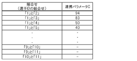
- FIG. 10 shows the storage contents of the parameter table.
- the parameter table is data in which a combination of IDs of two player objects 44 is associated with a linkage parameter C.
- the cooperation parameter C is data obtained by quantifying the degree of cooperation between the two player objects 44, and corresponds to a parameter related to the relationship between the two player objects 44.
- the parameter table is set so that the value of the cooperation parameter C increases as the cooperation between the two player objects 44 increases.
- the parameter condition table is stored in the optical disc 32.
- FIG. 11 shows the stored contents of the parameter condition table.
- the parameter condition table is data in which the parameter condition related to the linkage parameter C is associated with the size data for controlling the size of the determination area 51.
- the value of the radius Rj of the determination area 51 is stored as size data.
- the parameter condition table is set so that the value of the radius Rj increases as the value of the cooperation parameter C increases.
- the designated position acquisition unit 64 (designated position acquisition means) is realized mainly by the microprocessor 13, the controller interface 20, and the operation input unit 21.
- the designated position acquisition unit 64 acquires a position on the game screen designated by the user.
- the indicated position acquisition unit 64 acquires the screen coordinate value of the position P indicated by the front end 22a of the controller 22 based on the operation signal transmitted from the controller 22 at regular intervals. Then, the indication position acquisition unit 64 acquires the indication area of the cursor 52 based on the position P indicated by the front end portion 22a of the controller 22.
- FIG. 12 is a diagram for explaining an instruction area of the cursor 52. As shown in FIG. 12, the pointing area 53 of the cursor 52 is a circular area having a radius Rc centered on the position P indicated by the front end 22 a of the controller 22. The indication area 53 of the cursor 52 coincides with the area where the cursor 52 is displayed.
- the instruction area 53 of the cursor 52 corresponds to a position group (a set of positions) on the game screen specified by the user. That is, each position in the instruction area 53 of the cursor 52 corresponds to a position on the game screen instructed by the user.
- the radius Rc of the pointing area 53 of the cursor 52 is a fixed value.
- the instruction area 53 of the cursor 52 is simply referred to as “instruction area 53”.
- the game control unit 66 is realized mainly by the microprocessor 13, for example.
- the game control unit 66 includes a determination area control unit 68, a determination unit 70, and a designation unit 72 as functions related to the present invention.
- the determination unit 70 determines whether any player object 44 (selection candidate image) is instructed by the user. That is, the determination unit 70 determines whether or not the position (instruction region 53) acquired by the instruction position acquisition unit 64 is included in the determination region 51 corresponding to any player object 44 (selection candidate image). . Details of the operation of the determination unit 70 will be described later (see S103 in FIG. 13).
- the designation unit 72 indicates that the position (instruction area 53) acquired by the indicated position acquisition unit 64 is any of the player objects 44.
- the player object 44 selected candidate image
- the player object 44 is selected as the selected player object (selected image). Is specified. Details of the operation of the designation unit 72 will be described later (see S104 in FIG. 13).
- the determination area control unit 68 determines corresponding to another player object 44 (selection candidate image).
- the size of the area 51 is stored in the parameter table in association with the combination of the player object 44 (selection candidate image) designated as the selected player object (selection image) and the other player object 44 (selection candidate image). Change based on the linkage parameter C. Details of the operation of the determination area control unit 68 will be described later (see S105 in FIG. 13).
- FIG. 13 and FIG. 14 are flowcharts showing an example of processing executed by the game apparatus 10. 13 and 14 are executed by the microprocessor 13 operating according to a program.
- the process shown in FIG. 13 is a process executed when the value of the selection flag of all the player objects 44 belonging to the operation target team is “0”. That is, the process shown in FIG. 13 is a process executed at regular intervals when no player object 44 belonging to the operation target team is selected as the operation target.
- the microprocessor 13 acquires the instruction area 53 (S101).
- the microprocessor 13 acquires the position P on the game screen indicated by the front end 22a of the controller 22 based on the operation signal supplied from the controller 22. Then, the microprocessor 13 acquires a circular area having a radius Rc centered on the acquired position P as the instruction area 53.
- the microprocessor 13 determines whether or not the selection button has been pressed based on the operation signal supplied from the controller 22 (S102). If the selection button has not been pressed (N in S102), the microprocessor 13 ends the process.
- the microprocessor 13 determines whether any of the player objects 44 belonging to the operation target team is indicated by the front end 22a of the controller 22. Is determined (S103). That is, the microprocessor 13 determines, for each player object 44, whether or not the player object 44 is indicated by the front end portion 22a of the controller 22.
- the microprocessor 13 when determining whether or not the player object X is pointed by the front end 22a of the controller 22, the microprocessor 13 refers to the game situation data (particularly, the position field and the determination area field), and the player object X The determination area 51 corresponding to is specified. Note that the size (radius Rj) of the determination area 51 corresponding to the player object X at this time is set to a predetermined initial value. Then, the microprocessor 13 determines whether or not at least a part of the instruction area 53 is included in the determination area 51 corresponding to the player object X. When at least a part of the instruction area 53 is included in the determination area 51 corresponding to the player object X, it is determined that the player object X is indicated by the front end 22 a of the controller 22.
- the microprocessor 13 ends the process.
- the microprocessor 13 (designating means) is indicated by the front end 22a of the controller 22.
- the value of the selection flag of the player object 44 shown is set to “1” (S104). In this case, the value of the selection flag of the other player object 44 is set to “0”.
- the microprocessor 13 determines the determination area corresponding to the other player object 44 belonging to the operation target team.
- the size of 51 is changed (S105). That is, the size of the determination area 51 corresponding to the player object 44 whose selection flag value is set to “0” among the player objects 44 belonging to the operation target team is changed.
- the microprocessor 13 acquires the linkage parameter C associated with the combination of the player object X and the player object Y from the parameter table. Thereafter, the microprocessor 13 refers to the parameter condition table and identifies a parameter condition that satisfies the acquired linkage parameter C. Then, the microprocessor 13 updates the value of the radius Rj stored in the determination area field (see FIG. 9) of the player object Y based on the size data associated with the parameter condition.
- the process shown in FIG. 14 is a process executed when the value of the selection flag of any player object 44 belonging to the operation target team is “1”. That is, the process shown in FIG. 14 is executed at regular intervals when any player object 44 belonging to the operation target team is selected as the operation target.
- the microprocessor 13 acquires the instruction area 53 in the same manner as the step of S101 in FIG. 13 (S201).
- the microprocessor 13 determines whether or not the path instruction button is pressed based on the operation signal supplied from the controller 22 (S202).
- the microprocessor 13 determines whether or not the player object 44 whose selection flag is “1” holds the ball object 42 (S203). When the player object 44 whose selection flag is “1” does not hold the ball object 42 (N in S203), the microprocessor 13 ends the process.
- the microprocessor 13 determines that any of the other player objects 44 belonging to the operation target team is the controller 22. It is determined whether or not it is indicated by the front end portion 22a. That is, the microprocessor 13 determines whether any of the player objects 44 whose selection flag is “0” is indicated by the front end 22a of the controller 22 (S204). More specifically, the microprocessor 13 determines, for each player object 44 whose selection flag is “0”, whether or not the player object 44 is indicated by the front end portion 22 a of the controller 22.
- the microprocessor 13 determines whether or not the player object X is pointed by the front end portion 22a of the controller 22, a determination region in which at least a part of the instruction region 53 corresponds to the player object X 51 is determined.
- the determination area 51 corresponding to the player object X is specified by the content of the determination area field (see FIG. 9) after the change in step S105 of FIG.
- the instruction area 53 is included in the determination area 51 corresponding to the player object X, it is determined that the player object X is indicated by the front end 22 a of the controller 22.
- the microprocessor 13 ends the processing. On the other hand, when any of the player objects 44 whose selection flag is “0” is indicated by the front end 22a of the controller 22 (Y in S204), the microprocessor 13 is indicated by the front end 22a of the controller 22. A pass to the player object 44 being executed is executed (S205).
- the microprocessor 13 determines whether or not a selection cancel button (for example, the button 37a) has been pressed (S206). If the selection cancel button has not been pressed (N in S206), the microprocessor 13 ends the process. On the other hand, when the selection cancel button is pressed (Y in S206), the microprocessor 13 sets the value of the selection flag of the player object 44 whose selection flag is “1” to “0” (S207). By the step of S207, all the player objects 44 belonging to the operation target team are no longer operation targets. Further, the microprocessor 13 initializes the size of the determination area 51 for all the player objects 44 belonging to the operation target team (S208). Specifically, the value (radius Rj) of the determination area field is updated to a predetermined initial value for all player objects 44.
- a selection cancel button for example, the button 37a
- the ease of selecting a pass partner when selecting another player object 44 as a pass partner of the player object 44 holding the ball object 42 is as follows. It changes in accordance with the combination of the player object 44 holding the ball object 42 and another player object 44 that is a candidate for the pass opponent.
- the relationship between the player object 44 holding the ball object 42 and another player object 44 that is a candidate for a pass partner (for example, compatibility or cooperation is good or bad). ) Can be realized by the user.
- the ease of selection when the other player object 44 is selected as the pass partner or the like is selected. It has been changed by changing the size of the determination area 51 corresponding to the player object 44.
- the second embodiment is characterized in that, instead of changing the size of the determination area 51, the size of the instruction area 53 of the cursor 52 is changed. That is, in the second embodiment, the ease of selecting another player object 44 when any one of the player objects 44 belonging to the operation target team is selected as the operation target is the size of the instruction area 53 (radius Rc). It is characterized in that it can be changed by changing.
- Embodiment 2 will be described. Note that the hardware configuration of the game apparatus 10 according to the second embodiment is the same as that of the first embodiment (see FIGS. 1 to 3), and thus description thereof is omitted here. Also, in the game device 10 according to the second embodiment, for example, a soccer game is executed.
- FIG. 15 is a functional block diagram showing a function group realized in the game apparatus 10.
- a display control unit 60 a game data storage unit 62a, an instruction area acquisition unit 64a, and a game control unit 66a are realized. These functions are realized by the microprocessor 13 operating according to a program read from the optical disc 32.
- the function of the display control part 60 is the same as that of Embodiment 1, description is abbreviate
- the game data storage unit 62a stores game situation data, a parameter table, and a parameter condition table, similarly to the game data storage unit 62 in the first embodiment.
- the parameter condition table is different from that of the first embodiment, the parameter condition table will be described here.
- FIG. 16 shows an example of the parameter condition table in the second embodiment.
- the parameter condition table shown in the figure is data in which the parameter condition related to the linkage parameter C is associated with the size data for controlling the size of the instruction area 53. That is, in the parameter condition table in the second embodiment, size data for controlling the size of the instruction area 53 is stored, not size data for controlling the size of the determination area 51 (see FIG. 11).
- the value of the radius Rc of the indication area 53 is stored.
- the parameter condition table is set so that the value of the radius Rc increases as the value of the linkage parameter C increases.
- the game data storage unit 62a in the second embodiment stores instruction area data regarding the current size of the instruction area 53.
- the size of the indication area 53 is the size of the area of the indication area 53 when the indication area 53 is a two-dimensional area, and the indication area when the indication area 53 is a three-dimensional area. 53 volume size.
- the indication area data is data indicating the current value of the radius Rc of the indication area 53.
- the instruction area data is data indicating the length of each side of the instruction area 53 (rectangular area).
- the instruction area acquisition unit 64a (instruction area acquisition means) is realized mainly by the microprocessor 13, the controller interface 20, and the operation input unit 21.
- the instruction area acquisition unit 64a acquires an area on the game screen instructed by the user. In the case of this embodiment, the instruction area acquisition unit 64 a acquires the instruction area 53.
- the instruction area 53 is an area that coincides with an area where the cursor 52 is displayed. Details of the operation of the instruction area acquisition unit 64a will be described later (see S301 in FIG. 17).
- the game control unit 66a in the second embodiment includes a determination unit 70a, a designation unit 72a, a specifying unit 80, and an instruction area control unit 82.
- the determination unit 70a determines whether or not the instruction region 53 acquired by the instruction region acquisition unit 64a is included in the determination region 51 corresponding to any player object 44 (selection candidate image). Details of the operation of the determination unit 70a will be described later (see S303 in FIG. 17).
- the designation section 72a When it is determined that the instruction area 53 acquired by the instruction area acquisition section 64a is included in the determination area 51 corresponding to any player object 44 (selection candidate image), the designation section 72a The selection candidate image) is designated as the selected player object (selected image). Details of the operation of the designation unit 72a will be described later (see S304 in FIG. 17).
- the specifying unit 80 is assigned to another player object belonging to the operation target team.
- 44 selection candidate images
- the player object 44 selection candidate image having the shortest distance from the instruction area 53 is specified. Details of the operation of the specifying unit 80 will be described later (see S401 in FIG. 18).
- the instruction area control unit 82 associates with the combination of the player object 44 (selection candidate image) specified as the selected player object (selection image) and the player object 44 (selection candidate image) specified by the specifying unit 80.
- the size of the instruction area 53 is changed based on the parameters stored in the parameter table. Details of the operation of the instruction area control unit 82 will be described later (see S402 in FIG. 18).
- FIG. 17 and 18 are flowcharts showing an example of processing executed by the game device 10 according to the second embodiment. 17 and 18 are executed by the microprocessor 13 operating according to a program.
- the process shown in FIG. 17 corresponds to the process shown in FIG. 13 in the first embodiment. That is, the process shown in FIG. 17 is a process executed when the value of the selection flag of all the player objects 44 belonging to the operation target team is “0”. That is, the process shown in FIG. 17 is a process executed at regular intervals when no player object 44 belonging to the operation target team is selected as the operation target.
- the microprocessor 13 acquires the instruction area 53 (S301).
- step S ⁇ b> 301 the microprocessor 13 acquires a position P on the game screen indicated by the front end 22 a of the controller 22 based on the operation signal supplied from the controller 22. Thereafter, the microprocessor 13 refers to the instruction area data and acquires the radius Rc of the current instruction area 53. At this time, the size (radius Rc) of the instruction area 53 is set to a predetermined initial value. Then, the microprocessor 13 acquires a circular area having a radius Rc centered on the position P as the indication area 53.
- the microprocessor 13 determines whether or not the selection button has been pressed based on the operation signal supplied from the controller 22 (S302). If the selection button has not been pressed (N in S302), the microprocessor 13 ends the process.
- the microprocessor 13 determines whether any of the player objects 44 belonging to the operation target team is pointed to by the front end portion 22a of the controller 22 ( S303). The process in this step is the same as the process in step S103 in FIG.
- the microprocessor 13 ends the process.
- the microprocessor 13 (designating means) is indicated by the front end 22a of the controller 22.
- the value of the selection flag of the player object 44 shown is set to “1” (S304). The process in this step is the same as the process in step S104 in FIG.
- the process shown in FIG. 18 corresponds to the process shown in FIG. 14 in the first embodiment. That is, the process shown in FIG. 18 is a process executed when the value of the selection flag of any player object 44 belonging to the operation target team is “1”. That is, the process shown in FIG. 18 is executed at regular intervals when any player object 44 belonging to the operation target team is selected as the operation target.
- the player object 44 having a selection flag value of “1”, that is, the player object 44 in a state selected as an operation target is referred to as “player object X”.
- the microprocessor 13 specifies the player object 44 having the shortest distance from the instruction area 53 among the player objects 44 other than the player object X among the player objects 44 belonging to the operation target team (S401). That is, the microprocessor 13 (specifying means) specifies the player object 44 that belongs to the operation target team and has the shortest distance from the instruction area 53 among the player objects 44 whose selection flag value is “0”. To do.
- step S401 the microprocessor 13 relates to each of the player objects 44 whose selection flag value is “0”, that is, the position P on the game screen indicated by the center point of the instruction area 53 (ie, the front end 22a of the controller 22). ) To the display position of the player object 44 is acquired.
- the “display position of the player object 44” is obtained by converting the world coordinate value of the representative point of the player object 44 (the coordinate value of the XW-YW-ZW coordinate system in FIG. 4) into a screen coordinate value by a predetermined coordinate conversion calculation. Is obtained by And the player object 44 with the shortest distance from the instruction
- the player object 44 identified in step S401 is referred to as “player object Y”.
- the microprocessor 13 changes the size of the instruction area 53 (S402).
- the microprocessor 13 acquires the linkage parameter C associated with the combination of the player object X and the player object Y from the parameter table. Thereafter, the microprocessor 13 refers to the parameter condition table and identifies a parameter condition that satisfies the acquired linkage parameter C. Then, the microprocessor 13 updates the instruction area data (the value of the radius Rc of the instruction area 53) based on the size data associated with the parameter condition.
- the microprocessor 13 acquires the designated area 53 in the same manner as in step S301 in FIG. 17 (S403). After the instruction area 53 is acquired, the microprocessor 13 executes the processes of S202 to S208 shown in FIG. 14 as in the first embodiment. However, in the second embodiment, in step S208, instead of initializing the size of the determination area 51, the size of the instruction area 53 is initialized. That is, the instruction area data is initialized, and the radius Rc of the instruction area 53 is set to a predetermined initial value.
- the size of the instruction area 53 when the other player object 44 is selected as the pass partner of the player object 44 holding the ball object 42 is the ball object 42. Is changed in accordance with the combination of the player object 44 holding the character and another player object 44 that is a candidate of the pass partner.
- the linkage parameter C corresponding to the combination of the player object 44 holding the ball object 42 and another player object 44 that is a candidate for a pass partner is high, the size of the instruction area 53 is increased. . In this case, the user can easily select the player object 44 as a pass partner.
- the linkage parameter C corresponding to the combination of the player object 44 holding the ball object 42 and another player object 44 that is a candidate for a pass partner is low, the size of the instruction area 53 is small. . In this case, it becomes difficult for the user to select the player object 44 as a pass partner.
- the ease of selecting a pass opponent is determined by the player object 44 holding the ball object 42 and the other player objects 44 that are candidates for the pass opponent. It changes according to the combination.
- the relationship between the player object 44 holding the ball object 42 and another player object 44 that is a candidate for the pass opponent (for example, whether compatibility or cooperation is good or bad). It is possible to make the user feel it.
- FIG. 19 is a functional block diagram showing a functional group realized by the game apparatus 10 in this modified example.
- a display control unit 60 in the game apparatus 10 in this case, a display control unit 60, a game data storage unit 62b, an instruction area acquisition unit 64a, and a game control unit 66b are realized.
- the display control unit 60 is the same as that of the first and second embodiments, and the instruction area acquisition unit 64a is the same as that of the second embodiment.
- the game data storage unit 62b stores data stored in the game data storage unit 62 (see FIG. 8) and the game data storage unit 62a (see FIG. 15). For example, both the parameter condition table shown in FIG. 12 and the parameter condition table shown in FIG. 16 are stored in the game data storage unit 62b.
- the game control unit 66b includes a determination region control unit 68, a determination unit 70a, a designation unit 72a, a specifying unit 80, and an instruction region control unit 82.
- the determination area control unit 68 is the same as that of the first embodiment, and the determination unit 70a, the designation unit 72a, the specifying unit 80, and the instruction area control unit 82 are the same as those of the second embodiment.
- step S101 the microprocessor 13 acquires the instruction area 53 based on the operation signal supplied from the controller 22 and the instruction area data stored in the game data storage unit 62b.
- the microprocessor 13 determineation area control means, first changing means
- the microprocessor 13 is in a state in which any of the player objects 44 belonging to the operation target team is selected as the operation target in the first embodiment or the first modification.
- the size of the determination area 51 corresponding to the other player object 44 may be changed according to the elapsed time from the reference timing.
- the microprocessor 13 is based on the linkage parameter C stored in the parameter table in association with the combination of the player object 44 that is selected as the operation target and the other player object 44. You may make it control the aspect to which the size of the determination area
- the parameter condition table shown in FIG. is data in which a parameter condition that is a condition relating to the linkage parameter C is associated with size data that is data for controlling a change in the size (radius Rj) of the determination region 51.
- RJ1 to RJ5 indicate the initial size of the determination area 51
- ⁇ RJ1 to ⁇ RJ5 indicate the amount of change in the size of the determination area 51 per unit time, that is, the enlargement speed of the determination area 51. Yes.
- the parameter condition table shown in FIG. 20 is set so that the initial sizes RJ1 to RJ5 of the determination area 51 become larger as the value of the linkage parameter C is larger. Further, the enlargement speeds ⁇ RJ1 to ⁇ RJ5 of the determination area 51 are set to increase as the value of the cooperation parameter C increases. That is, in the parameter condition table, the mode of change in the size of the determination area 51 (enlargement speed) changes according to the value of the linkage parameter C.
- the microprocessor 13 executes the processing shown in FIG.
- step S105 the microprocessor 13 changes the size of the determination area 51 as described below.
- step S105 in Example 2 will be described.
- the microprocessor 13 also executes the process shown in FIG. 14 in the second modification.
- the elapsed time T after any player object 44 is selected as the operation target is stored in the main memory 14. Further, the microprocessor 13 executes the same process as the process of step S105 before executing the process of step S201. Corresponding to the combination of the player object 44 that is selected as the operation target and the other player objects 44 belonging to the operation target team by executing the process of step S105 before the process of step S201. The size of the determination area 51 corresponding to the other player object 44 is changed in a mode (enlargement speed) based on the attached cooperation parameter C.
- the speed of enlargement of the size of the determination area 51 corresponding to the player object Y belonging to the operation target team is It changes according to the relationship with the player object Y (for example, compatibility or cooperation is good or bad).
- the ease of selection of the player object Y changes according to the relationship between the player object X and the player object Y.
- the initial sizes RJ1 to RJ5 of the determination area 51 may be constant values regardless of the value of the linkage parameter C.
- the enlargement speeds ⁇ RJ1 to ⁇ RJ5 of the determination area 51 may be set to a constant value regardless of the value of the linkage parameter C.
- the size (initial size) of the determination area 51 before changing the size of the determination area 51 according to the elapsed time T is related to the relationship between the player object X and the player object Y (for example, whether compatibility or cooperation is good or bad). It will change accordingly.
- the microprocessor 13 (instruction area control means, second changing means) is in a state in which any of the player objects 44 belonging to the operation target team is selected as the operation target in the second embodiment or the first modification.
- the size of the instruction area 53 may be changed according to the elapsed time from the reference timing.
- the microprocessor 13 is based on the linkage parameter C stored in the parameter table in association with the combination of the player object 44 that is selected as the operation target and the other player object 44. You may make it control the aspect which changes the size of the instruction
- the parameter condition table shown in FIG. is data in which a parameter condition that is a condition relating to the linkage parameter C is associated with size data that is data for controlling a change in the size (radius Rc) of the instruction area 53.
- RC1 to RC5 indicate the initial size of the instruction area 53
- ⁇ RC1 to ⁇ RC5 indicate the amount of change in the size of the instruction area 53 per unit time, that is, the enlargement speed of the instruction area 53. Yes.
- the parameter condition table shown in FIG. 21 is set so that the initial sizes RC1 to RC5 of the instruction area 53 become larger as the value of the linkage parameter C is larger. Further, the enlargement speeds ⁇ RC1 to ⁇ RC5 of the instruction area 53 are set to increase as the value of the cooperation parameter C increases. That is, in the parameter condition table, the change mode (enlargement speed) of the size of the instruction area 53 changes according to the value of the linkage parameter C.
- the microprocessor 13 executes the processing shown in FIG. 13 or FIG.
- the microprocessor 13 when any player object 44 belonging to the operation target team is selected as the operation target, the microprocessor 13 also executes the process shown in FIG. 18 in the third modification.
- the microprocessor 13 changes the size of the instruction area 53 as described below.
- the case where the player object 44 selected as the operation target is the player object X and the player object 44 specified in the process of step S401 is the player object Y is an example of S402 in the third modification. Step processing will be described.
- the microprocessor 13 acquires the linkage parameter C associated with the combination of the player object X and the player object Y from the parameter table. Thereafter, the microprocessor 13 refers to the parameter condition table and identifies a parameter condition that satisfies the acquired linkage parameter C. Then, the microprocessor 13 updates the instruction area data (the value of the radius Rc of the instruction area 53) based on the size data associated with the parameter condition and the elapsed time T.
- step S402 the cooperation parameter C associated with the combination of the player object 44 selected as the operation target and the other player object 44 belonging to the operation target team is set.
- the size of the instruction area 53 is changed in a mode (enlargement speed) based on the above.
- the speed of enlargement of the size of the instruction area 53 is the relationship between the player object X and the player object Y (for example, compatibility or cooperation It changes according to the good or bad).
- the ease of selection of the player object Y changes according to the relationship between the player object X and the player object Y.
- the initial sizes RC1 to RC5 of the instruction area 53 may be set to a constant value regardless of the value of the linkage parameter C.
- the enlargement speeds ⁇ RC1 to ⁇ RC5 of the instruction area 53 may be constant values regardless of the value of the linkage parameter C.
- the size (initial size) of the instruction area 53 before changing the size of the instruction area 53 according to the elapsed time T is related to the relationship between the player object X and the player object Y (for example, whether compatibility or cooperation is good or bad). It will change accordingly. Even if it does in this way, since the ease of selection of the player object Y changes according to the relationship between the player object X and the player object Y (e.g., compatibility or good or bad), the user can feel the relationship between the player object X and the player object Y. It becomes possible to make it.
- the size of the determination area 51 corresponding to the player object 44 may be changed based on the moving direction or / and moving speed of the player object 44.
- the determination area 51 corresponding to the player object 44 may be extended in the moving direction of the player object 44.
- the degree of expansion of the determination area 51 of the player object 44 may be controlled based on the moving speed of the player object 44.
- the extent of extension of the determination area 51 may be increased as the moving speed of the player object 44 increases.
- the determination area 51 corresponding to the player object 44 may be enlarged based on the moving speed of the player object 44. More specifically, the degree of expansion of the determination area 51 corresponding to the player object 44 may be controlled based on the moving speed of the player object 44. For example, the degree of enlargement of the determination area 51 may be increased as the moving speed of the player object 44 increases.
- the determination area control unit 68 is selected as the operation target. You may make it change the size of the determination area
- the determination region control unit 68 is selected as the operation target. You may make it change the size of the determination area
- the interface for the user to specify the position in the game screen is not limited to the interface described above.
- the microprocessor 13 may move the cursor 52 in the direction designated by the user using the direction button 36.
- the pointing position acquisition unit 64 and the pointing region acquisition unit 64a use the center position of the cursor 52 instead of the position P indicated by the front end 22a of the controller 22.
- the interface for the user to specify the position in the game screen may be a touch panel installed on the monitor 30 (for example, a liquid crystal monitor).
- the instruction position acquisition unit 64 and the instruction region acquisition unit 64a use the position in the game screen pressed by the user instead of the position P indicated by the front end 22a of the controller 22.
- the present invention is also applicable when a game other than a sports game is provided on the game apparatus 10.
- the present invention can also be applied to the case where the game device 10 provides an action game in which a plurality of characters (selection candidate images) are displayed on the game screen.
- selection candidate images For example, when the user selects the first character as the operation target and then selects the second character by directing the front end 22a of the controller 22 toward the second character, the first character magically acts on the second character.
- the present invention can also be applied to the case where a game that applies a game is provided in the game apparatus 10.
Landscapes
- Engineering & Computer Science (AREA)
- Multimedia (AREA)
- Human Computer Interaction (AREA)
- Theoretical Computer Science (AREA)
- User Interface Of Digital Computer (AREA)
- Processing Or Creating Images (AREA)
Abstract
L'invention concerne un dispositif de jeu qui permet à un utilisateur, au moment où celui-ci sélectionne une image candidate de sélection, de faire une relation avec une autre image candidate de sélection. Des moyens de détermination (70a) déterminent si une zone indiquée par l'utilisateur est incluse dans une zone de détermination correspondant à une image candidate de sélection. Quand la zone indiquée est incluse dans la zone de détermination, des moyens de désignation (72a) désignent comme image sélectionnée l'image candidate de sélection correspondant à la zone de détermination. Des moyens (68) de commande de zone de détermination font varier, sur la base d'un paramètre stocké en association avec la combinaison de l'image candidate de sélection désignée comme image sélectionnée et d'une autre image candidate de sélection, les dimensions de la zone de détermination correspondant à l'autre image candidate de sélection. Des moyens de commande (82) de zone indiquée font varier les dimensions de la zone indiquée sur la base d'un paramètre stocké en association avec la combinaison de l'image candidate de sélection désignée comme image sélectionnée et de l'image candidate de sélection qui se situe le plus près de la zone indiquée.
Priority Applications (1)
| Application Number | Priority Date | Filing Date | Title |
|---|---|---|---|
| US13/262,173 US8485898B2 (en) | 2009-03-31 | 2009-10-22 | Game device, method for controlling game device, program, and information storage medium |
Applications Claiming Priority (2)
| Application Number | Priority Date | Filing Date | Title |
|---|---|---|---|
| JP2009-088546 | 2009-03-31 | ||
| JP2009088546A JP5210228B2 (ja) | 2009-03-31 | 2009-03-31 | ゲーム装置、ゲーム装置の制御方法、及びプログラム |
Publications (1)
| Publication Number | Publication Date |
|---|---|
| WO2010113345A1 true WO2010113345A1 (fr) | 2010-10-07 |
Family
ID=42827668
Family Applications (1)
| Application Number | Title | Priority Date | Filing Date |
|---|---|---|---|
| PCT/JP2009/068209 WO2010113345A1 (fr) | 2009-03-31 | 2009-10-22 | Dispositif de jeu, procédé de commande de dispositif de jeu, programme et support de stockage de données |
Country Status (3)
| Country | Link |
|---|---|
| US (1) | US8485898B2 (fr) |
| JP (1) | JP5210228B2 (fr) |
| WO (1) | WO2010113345A1 (fr) |
Families Citing this family (5)
| Publication number | Priority date | Publication date | Assignee | Title |
|---|---|---|---|---|
| JP5210228B2 (ja) * | 2009-03-31 | 2013-06-12 | 株式会社コナミデジタルエンタテインメント | ゲーム装置、ゲーム装置の制御方法、及びプログラム |
| JP5122669B2 (ja) * | 2011-06-06 | 2013-01-16 | 株式会社コナミデジタルエンタテインメント | ゲーム装置、ゲーム装置の制御方法、及びプログラム |
| JP5103544B1 (ja) * | 2011-06-14 | 2012-12-19 | 株式会社コナミデジタルエンタテインメント | ゲーム装置、ゲーム装置の制御方法、及びプログラム |
| US20150130723A1 (en) * | 2013-11-08 | 2015-05-14 | Microsoft Corporation | Two step content selection with trajectory copy |
| JP6459308B2 (ja) * | 2014-08-28 | 2019-01-30 | 株式会社セガゲームス | プログラムおよびゲーム装置 |
Citations (3)
| Publication number | Priority date | Publication date | Assignee | Title |
|---|---|---|---|---|
| JP2001232066A (ja) * | 2000-02-23 | 2001-08-28 | Namco Ltd | ゲーム装置及び陣形形成方法、記録媒体 |
| JP2005218779A (ja) * | 2004-02-09 | 2005-08-18 | Nintendo Co Ltd | ゲーム装置およびゲームプログラム |
| JP2008154777A (ja) * | 2006-12-22 | 2008-07-10 | Konami Digital Entertainment:Kk | ゲーム装置、ゲーム装置の制御方法及びプログラム |
Family Cites Families (5)
| Publication number | Priority date | Publication date | Assignee | Title |
|---|---|---|---|---|
| JP3262677B2 (ja) | 1994-05-02 | 2002-03-04 | 株式会社ワコム | 情報入力装置 |
| US6674905B1 (en) * | 1999-01-22 | 2004-01-06 | Canon Kabushiki Kaisha | Image processing method, image processing apparatus, and storage medium |
| US7578742B2 (en) * | 2004-03-26 | 2009-08-25 | Nintendo Co., Ltd. | Recording medium storing video game program and video game device |
| JP2008264297A (ja) * | 2007-04-23 | 2008-11-06 | Namco Bandai Games Inc | ゲームシステム、プログラム及び情報記憶媒体 |
| JP5210228B2 (ja) * | 2009-03-31 | 2013-06-12 | 株式会社コナミデジタルエンタテインメント | ゲーム装置、ゲーム装置の制御方法、及びプログラム |
-
2009
- 2009-03-31 JP JP2009088546A patent/JP5210228B2/ja active Active
- 2009-10-22 US US13/262,173 patent/US8485898B2/en active Active
- 2009-10-22 WO PCT/JP2009/068209 patent/WO2010113345A1/fr active Application Filing
Patent Citations (3)
| Publication number | Priority date | Publication date | Assignee | Title |
|---|---|---|---|---|
| JP2001232066A (ja) * | 2000-02-23 | 2001-08-28 | Namco Ltd | ゲーム装置及び陣形形成方法、記録媒体 |
| JP2005218779A (ja) * | 2004-02-09 | 2005-08-18 | Nintendo Co Ltd | ゲーム装置およびゲームプログラム |
| JP2008154777A (ja) * | 2006-12-22 | 2008-07-10 | Konami Digital Entertainment:Kk | ゲーム装置、ゲーム装置の制御方法及びプログラム |
Also Published As
| Publication number | Publication date |
|---|---|
| JP2010239987A (ja) | 2010-10-28 |
| US20120021830A1 (en) | 2012-01-26 |
| US8485898B2 (en) | 2013-07-16 |
| JP5210228B2 (ja) | 2013-06-12 |
Similar Documents
| Publication | Publication Date | Title |
|---|---|---|
| JP4171039B2 (ja) | ゲーム装置、ゲーム装置の制御方法及びプログラム | |
| JP4171040B2 (ja) | ゲーム装置、ゲーム装置の制御方法及びプログラム | |
| JP4247218B2 (ja) | ゲーム装置、ゲーム装置の制御方法及びプログラム | |
| JP4447568B2 (ja) | ゲーム装置、ゲーム装置の制御方法及びプログラム | |
| WO2010021182A1 (fr) | Dispositif de jeu, procédé de commande d'un dispositif de jeu, programme et support de mémorisation d'informations | |
| JP4838223B2 (ja) | ゲーム装置、ゲーム装置の制御方法及びプログラム | |
| JP4498447B2 (ja) | ゲーム装置、ゲーム装置の制御方法及びプログラム | |
| JP5214215B2 (ja) | ゲーム装置、ゲーム装置の制御方法及びプログラム | |
| JP5210228B2 (ja) | ゲーム装置、ゲーム装置の制御方法、及びプログラム | |
| EP2135648B1 (fr) | Dispositif de jeu, procédé de commande de dispositif de jeu, et support de stockage d'informations | |
| JP4399472B2 (ja) | ゲーム装置、ゲーム装置の制御方法及びプログラム | |
| WO2012172859A1 (fr) | Dispositif de jeu, procédé de commande de dispositif de jeu, programme et support de stockage d'informations | |
| JP2008225779A (ja) | 情報処理装置、情報処理装置の制御方法及びプログラム | |
| WO2012169296A1 (fr) | Dispositif de jeu, procédé de commande d'un dispositif de jeu, programme et support de stockage d'informations | |
| JP5027180B2 (ja) | ゲーム装置、ゲーム装置の制御方法及びプログラム | |
| JP5540127B2 (ja) | ゲーム装置、ゲーム装置の制御方法及びプログラム | |
| JP4847594B2 (ja) | 画像生成装置、画像生成方法及びプログラム | |
| JP5017212B2 (ja) | ゲーム装置、ゲーム装置の制御方法及びプログラム | |
| JP4960942B2 (ja) | ゲーム装置、ゲーム装置の制御方法及びプログラム | |
| JP5536467B2 (ja) | ゲーム装置、ゲーム装置の制御方法及びプログラム | |
| JP4113083B2 (ja) | ゲーム装置、ゲーム装置の制御方法及びプログラム | |
| JP4976023B2 (ja) | ゲーム装置、ゲーム装置の制御方法及びプログラム | |
| JP5540128B2 (ja) | ゲーム装置、ゲーム装置の制御方法及びプログラム |
Legal Events
| Date | Code | Title | Description |
|---|---|---|---|
| 121 | Ep: the epo has been informed by wipo that ep was designated in this application |
Ref document number: 09842696 Country of ref document: EP Kind code of ref document: A1 |
|
| WWE | Wipo information: entry into national phase |
Ref document number: 13262173 Country of ref document: US |
|
| NENP | Non-entry into the national phase |
Ref country code: DE |
|
| 122 | Ep: pct application non-entry in european phase |
Ref document number: 09842696 Country of ref document: EP Kind code of ref document: A1 |