WO2010095734A1 - ガーニッシュ取付構造 - Google Patents
ガーニッシュ取付構造 Download PDFInfo
- Publication number
- WO2010095734A1 WO2010095734A1 PCT/JP2010/052601 JP2010052601W WO2010095734A1 WO 2010095734 A1 WO2010095734 A1 WO 2010095734A1 JP 2010052601 W JP2010052601 W JP 2010052601W WO 2010095734 A1 WO2010095734 A1 WO 2010095734A1
- Authority
- WO
- WIPO (PCT)
- Prior art keywords
- pair
- fitting hole
- width direction
- vehicle width
- head
- Prior art date
- Legal status (The legal status is an assumption and is not a legal conclusion. Google has not performed a legal analysis and makes no representation as to the accuracy of the status listed.)
- Ceased
Links
Images




Classifications
-
- B—PERFORMING OPERATIONS; TRANSPORTING
- B60—VEHICLES IN GENERAL
- B60R—VEHICLES, VEHICLE FITTINGS, OR VEHICLE PARTS, NOT OTHERWISE PROVIDED FOR
- B60R13/00—Elements for body-finishing, identifying, or decorating; Arrangements or adaptations for advertising purposes
- B60R13/04—External Ornamental or guard strips; Ornamental inscriptive devices thereon
-
- F—MECHANICAL ENGINEERING; LIGHTING; HEATING; WEAPONS; BLASTING
- F16—ENGINEERING ELEMENTS AND UNITS; GENERAL MEASURES FOR PRODUCING AND MAINTAINING EFFECTIVE FUNCTIONING OF MACHINES OR INSTALLATIONS; THERMAL INSULATION IN GENERAL
- F16B—DEVICES FOR FASTENING OR SECURING CONSTRUCTIONAL ELEMENTS OR MACHINE PARTS TOGETHER, e.g. NAILS, BOLTS, CIRCLIPS, CLAMPS, CLIPS OR WEDGES; JOINTS OR JOINTING
- F16B21/00—Means for preventing relative axial movement of a pin, spigot, shaft or the like and a member surrounding it; Stud-and-socket releasable fastenings
- F16B21/06—Releasable fastening devices with snap-action
- F16B21/08—Releasable fastening devices with snap-action in which the stud, pin, or spigot has a resilient part
- F16B21/086—Releasable fastening devices with snap-action in which the stud, pin, or spigot has a resilient part the shank of the stud, pin or spigot having elevations, ribs, fins or prongs intended for deformation or tilting predominantly in a direction perpendicular to the direction of insertion
-
- F—MECHANICAL ENGINEERING; LIGHTING; HEATING; WEAPONS; BLASTING
- F16—ENGINEERING ELEMENTS AND UNITS; GENERAL MEASURES FOR PRODUCING AND MAINTAINING EFFECTIVE FUNCTIONING OF MACHINES OR INSTALLATIONS; THERMAL INSULATION IN GENERAL
- F16B—DEVICES FOR FASTENING OR SECURING CONSTRUCTIONAL ELEMENTS OR MACHINE PARTS TOGETHER, e.g. NAILS, BOLTS, CIRCLIPS, CLAMPS, CLIPS OR WEDGES; JOINTS OR JOINTING
- F16B21/00—Means for preventing relative axial movement of a pin, spigot, shaft or the like and a member surrounding it; Stud-and-socket releasable fastenings
- F16B21/06—Releasable fastening devices with snap-action
- F16B21/08—Releasable fastening devices with snap-action in which the stud, pin, or spigot has a resilient part
- F16B21/088—Releasable fastening devices with snap-action in which the stud, pin, or spigot has a resilient part the stud, pin or spigot being integrally formed with the component to be fastened, e.g. forming part of the sheet, plate or strip
-
- F—MECHANICAL ENGINEERING; LIGHTING; HEATING; WEAPONS; BLASTING
- F16—ENGINEERING ELEMENTS AND UNITS; GENERAL MEASURES FOR PRODUCING AND MAINTAINING EFFECTIVE FUNCTIONING OF MACHINES OR INSTALLATIONS; THERMAL INSULATION IN GENERAL
- F16B—DEVICES FOR FASTENING OR SECURING CONSTRUCTIONAL ELEMENTS OR MACHINE PARTS TOGETHER, e.g. NAILS, BOLTS, CIRCLIPS, CLAMPS, CLIPS OR WEDGES; JOINTS OR JOINTING
- F16B5/00—Joining sheets or plates, e.g. panels, to one another or to strips or bars parallel to them
- F16B5/06—Joining sheets or plates, e.g. panels, to one another or to strips or bars parallel to them by means of clamps or clips
- F16B5/0607—Joining sheets or plates, e.g. panels, to one another or to strips or bars parallel to them by means of clamps or clips joining sheets or plates to each other
- F16B5/0621—Joining sheets or plates, e.g. panels, to one another or to strips or bars parallel to them by means of clamps or clips joining sheets or plates to each other in parallel relationship
- F16B5/065—Joining sheets or plates, e.g. panels, to one another or to strips or bars parallel to them by means of clamps or clips joining sheets or plates to each other in parallel relationship the plates being one on top of the other and distanced from each other, e.g. by using protrusions to keep contact and distance
-
- F—MECHANICAL ENGINEERING; LIGHTING; HEATING; WEAPONS; BLASTING
- F16—ENGINEERING ELEMENTS AND UNITS; GENERAL MEASURES FOR PRODUCING AND MAINTAINING EFFECTIVE FUNCTIONING OF MACHINES OR INSTALLATIONS; THERMAL INSULATION IN GENERAL
- F16B—DEVICES FOR FASTENING OR SECURING CONSTRUCTIONAL ELEMENTS OR MACHINE PARTS TOGETHER, e.g. NAILS, BOLTS, CIRCLIPS, CLAMPS, CLIPS OR WEDGES; JOINTS OR JOINTING
- F16B5/00—Joining sheets or plates, e.g. panels, to one another or to strips or bars parallel to them
- F16B5/06—Joining sheets or plates, e.g. panels, to one another or to strips or bars parallel to them by means of clamps or clips
- F16B5/0607—Joining sheets or plates, e.g. panels, to one another or to strips or bars parallel to them by means of clamps or clips joining sheets or plates to each other
- F16B5/0621—Joining sheets or plates, e.g. panels, to one another or to strips or bars parallel to them by means of clamps or clips joining sheets or plates to each other in parallel relationship
- F16B5/0657—Joining sheets or plates, e.g. panels, to one another or to strips or bars parallel to them by means of clamps or clips joining sheets or plates to each other in parallel relationship at least one of the plates providing a raised structure, e.g. of the doghouse type, for connection with the clamps or clips of the other plate
Definitions
- the present invention relates to a garnish attachment structure for attaching a garnish covering a door frame to a door frame constituting a window frame of a vehicle door.
- Patent Document 1 discloses an example of a garnish mounting structure.
- FIG. 5 is a side view of an upper part of a vehicle door to which such a conventional garnish mounting structure is applied as seen from the outside in the vehicle width direction
- FIG. 6 is a cross-sectional view taken along line 6-6 in FIG.
- a garnish 93 that covers the frame portion 92 from the outside in the vehicle width direction is attached to the frame portion 92 on the vehicle rear side of the door frame 91 that constitutes the window frame of the vehicle door.
- the frame portion 92 is formed, for example, by roll forming a metal plate, and has a substantially constant cross-sectional shape in the longitudinal direction. As shown in FIG. 6, the frame portion 92 has a plate-like attachment portion 92a that forms the rear edge portion of the frame portion 92, and penetrates the attachment portion 92a in the plate thickness direction (vertical direction in FIG. 6). Fitting hole 92b.
- the garnish 93 has a rib 93a extending toward the attachment portion 92a so as to be fitted into the fitting hole 92b.
- the garnish 93 is attached to the frame portion 92 by fitting the rib 93a into the fitting hole 92b.
- the fitting hole 92b into which the rib 93a of the garnish 93 is fitted is formed in the plate-like attachment portion 92a, the rust attached to the attachment location (rib 93a and the like) and the portion around the fitting hole 92b. And the like are exposed to the inside in the vehicle width direction (inside the vehicle door) and the appearance is impaired.
- a clip 94 that covers the rib 93a and a portion around the rib 93a from the inner side in the vehicle width direction is attached to the rib 93a.
- the rib 93a protrudes inward in the vehicle width direction from the fitting hole 92b with a sufficient amount of protrusion so as not to come out of the fitting hole 92b. Therefore, when the clip 94 is further attached to such a rib 93a so as to overlap from the inner side in the vehicle width direction, a large arrangement space is required in the length direction of the rib 93a, and the clip 94 and the vehicle body facing portion (cymen etc. ) No separation distance W1 from 95 is present or negligible.
- An object of the present invention is to provide a garnish mounting structure capable of improving appearance while suppressing an increase in arrangement space.
- an attachment structure having a door frame, a garnish, and a clip is provided according to an aspect of the present invention.
- the door frame is adapted to constitute a window frame of the vehicle door.
- the door frame has an attachment portion and a fitting hole.
- the attachment portion is formed of a single plate.
- the fitting hole penetrates the mounting portion in the thickness direction.
- the fitting hole has a square shape whose diagonal line coincides with a predetermined direction.
- the garnish covers the door frame from the outside in the vehicle width direction so as to face the mounting portion of the door frame.
- the garnish has a pair of ribs. The pair of ribs extend inward in the vehicle width direction so as to face the pair of end portions of the fitting hole on the diagonal line.
- the pair of ribs are arranged in parallel to each other with an interval in the predetermined direction.
- the clip is attached to the fitting hole.
- the clip has a head, a cylindrical section having a square cross section, and a locking claw.
- the head is joined to the peripheral edge of the fitting hole on the inner side in the vehicle width direction of the mounting portion.
- the cylindrical portion protrudes from the head and fits into the fitting hole.
- the locking claw is provided on the side surface of the cylindrical portion.
- the cylinder portion has a tip portion that protrudes outward from the fitting hole in the vehicle width direction of the attachment portion. A pair of corners arranged in the predetermined direction of the tip end part is sandwiched between the pair of ribs.
- the locking claw is locked to the peripheral edge of the fitting hole on the outer side in the vehicle width direction of the mounting portion.
- the clip is prevented from coming off from the fitting hole (attachment part) by the locking claw being locked to the outer peripheral edge of the fitting hole, and the garnish is
- the both corners in the predetermined direction of the tip portion protruding from the fitting hole of the cylindrical portion to the outside of the vehicle are sandwiched by the pair of ribs, thereby being attached to the door frame via the clip.
- the fitting hole is covered with the head portion that is joined to the periphery of the fitting hole on the vehicle inner side, so that the fitting hole, rust attached to the fitting hole, or the like is inside the vehicle. There is no exposure to the inside of the vehicle door, and the appearance can be improved.
- the head is joined to a peripheral portion on the vehicle inner side of the fitting hole, the protruding length from the mounting portion to the vehicle inner side is accommodated in the range of the thickness of the head, The increase in the arrangement space can be suppressed. Furthermore, since both the ribs sandwich the both corners in the predetermined direction of the cylindrical portion, the ribs are arranged so that the distance between them is the longest. Therefore, the locking claws can be arranged using a space formed between the ribs and the cylindrical portion. For example, the locking claws are provided only on a part of the four side surfaces of the cylindrical portion.
- FIG. 4A is a cross-sectional view taken along line 2a-2a in FIG. 4
- FIG. 4B is a cross-sectional view taken along line 2b-2b in FIG. 4
- FIG. 4C is provided on the inner side surface of the garnish and is attached with a clip.
- Sectional drawing which shows the conventional garnish attachment structure. which shows another example of this invention. Sectional drawing which shows the other example of this invention.
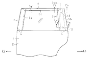
- FIG. 4 is a side view of the upper part of the vehicle door to which the garnish mounting structure according to the embodiment of the present invention is applied as viewed from the outside in the vehicle width direction.
- the vehicle door 1 is provided with the door main body 2 which comprises the lower part.
- the door main body 2 is a bag-like structure in which a door outer panel constituting a door outer plate and a door inner panel (not shown) constituting a door inner plate are combined.
- the door window glass DW etc. which can be projected and retracted from the upper opening of the door main body 2 are installed.
- the vehicle door 1 includes a door frame 5 attached to the upper end of the door body 2.
- the door frame 5 constitutes a window frame, that is, a frame that holds the edge of the door window glass DW.
- the door frame 5 is formed in a rectangular shape opened downward.
- the door frame 5 includes a front frame portion 5a and a rear frame portion 5b extending in the vehicle height direction, and a front frame portion 5a and a rear side portion extending between upper ends of the front frame portion 5a and the rear frame portion 5b.
- an upper frame part 5c fixed by welding is provided at each upper end of the frame part 5b.
- the lower end portion of the front frame portion 5a is fixed to the front upper end portion of the door body 2 (for example, door inner panel), and the lower end portion of the rear frame portion 5b is fixed to the rear upper end portion of the door body 2 (for example, door inner panel).
- the front frame portion 5a, the rear frame portion 5b, and the upper frame portion 5c are formed, for example, by roll forming a metal plate, and have a substantially constant cross-sectional shape in the longitudinal direction.
- the vehicle door 1 of the present embodiment is a rear door disposed behind the front door, and the front frame portion 5a and the rear frame portion 5b correspond to the B and C pillars of the vehicle body.
- the garnish 6 which consists of a board
- a garnish 7 made of a synthetic resin plate that covers the rear frame portion 5b from the vehicle width direction outer side (vehicle outer side) is attached to the rear frame portion 5b.
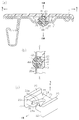
- FIG. 1A is a cross-sectional view taken along line 1a-1a in FIG. 4, and FIG. 1B is a cross-sectional view taken along line 1b-1b in FIG. 1A.
- 2 (a) and 2 (b) are cross-sectional views taken along lines 2a-2a and 2b-2b in FIG. 4, and
- FIG. 2 (c) shows the garnish 7 on the inner side in the vehicle width direction ( It is the perspective view seen from the back side.
- the rear frame portion 5b has a mounting portion 11 that faces the garnish 7.
- the mounting portion 11 is a single plate in which the metal plates do not overlap due to folding of the metal plates or the like.
- the attachment portion 11 is formed with a fitting hole 12 and a coupling hole 13 penetrating in the plate thickness direction.
- This fitting hole 12 is formed in the lower part of the rear side frame part 5b (attachment part 11).
- the cross-sectional shape of the fitting hole 12 is a square shape, and one of the two diagonal lines extends in the vehicle front-rear direction (predetermined direction).
- the coupling hole 13 is formed in the upper part of the rear side frame part 5b (attachment part 11).
- the garnish 7 has a pair of flat ribs 21 extending inward in the vehicle width direction (inner side of the vehicle). These ribs 21 are arranged at an interval corresponding to the width of the fitting hole 12 in the vehicle front-rear direction, and are arranged at both ends of the fitting hole 12 in the vehicle front-rear direction (two vertices in the square fitting hole 12). Opposite.
- the clip 30 is attached to the fitting hole 12.
- the clip 30 is made of, for example, a synthetic resin.
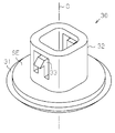
- the clip 30 includes a disc-shaped head portion 31 and a cylindrical section 32 having a square cross section that protrudes from the head portion 31 and fits into the fitting hole 12. Have.
- the head portion 31 is joined to the attachment portion 11 around the fitting hole 12.
- An annular seal material SE is disposed in a liquid-tight manner between the head portion 31 and the attachment portion 11 around the fitting hole 12.
- the four corners R of the cylindrical portion 32 are formed round, and specifically, formed on a circumferential surface R that coincides with a circle centered on the center line O of the cylindrical portion 32.
- a circumferential surface R that coincides with a circle centered on the center line O of the cylindrical portion 32.
- each locking claw 33 extends in a direction from the proximal end of the cylindrical portion 32 toward the distal end in the hole formed in the side surface of the cylindrical portion 32.
- a protruding portion that protrudes toward the outside of the cylindrical portion 32 is formed at the tip of each locking claw 33.
- Each locking claw 33 can be elastically deformed with its own base end connected to the cylindrical portion 32 as a fulcrum.
- the protruding portion of the locking claw 33 When the cylindrical portion 32 is inserted into the fitting hole 12, the protruding portion of the locking claw 33 is pressed against the inner wall of the fitting hole 12, so that the locking claw 33 is elastically deformed in the fitting hole 12. Enter. When the protruding portion of the locking claw 33 passes through the fitting hole 12, the locking claw 33 is elastically restored, and the protruding portion is locked to the mounting portion 11 around the fitting hole 12. Thereby, the clip 30 is prevented from coming off from the fitting hole 12 (attachment portion 11). That is, the clip 30 is fastened to the fitting hole 12 by the engaging force of the locking claw 33, and the sealing material SE is sandwiched between the head portion 31 and the mounting portion 11 and compressed to have a sealing property. .
- the pair of ribs 21 of the garnish 7 sandwich the tip portion of the cylindrical portion 32 protruding from the fitting hole 12 outward in the vehicle width direction in the vehicle front-rear direction.
- the rib 21 clamps the cylinder part 32 in the two corner
- the lower part of the garnish 7 is attached to the rear frame part 5 b (lower part of the attachment part 11) via the clip 30.
- the garnish 7 connects a pair of flat side walls 22 extending inward in the vehicle width direction and the ends of both side walls 22 connected to each other. And a flat support wall 23.
- the support wall portion 23 is formed at a position facing the coupling hole 13.
- the support wall 23 is formed with a mushroom-shaped locking groove 24 opened downward.
- the support wall 23 has a pair of extending pieces 23 a that extend obliquely upward so as to approach each other from the lower end of the support wall 23.
- the locking groove 24 has a guide hole 24a that gradually becomes narrower upward between the pair of extending pieces 23a.
- the garnish 7 has a pair of engagement wall portions 25 extending from the support wall portion 23 toward the vehicle width direction inward along the side wall portion 22 so as to be continuous with the side wall portion 22.
- a pair of locking projections 26 extending inward in the vehicle width direction are formed at the lower end of the support wall 23 and on both sides of the locking groove 24 (guide hole 24a).
- the locking projection 26 has a guide surface 26a that inclines toward the side (inner side in the vehicle width direction) that is gradually separated from the garnish 7 as it goes upward.
- the support wall portion 23, the both engagement wall portions 25, and the both locking projections 26 form a rectangular fitting recess 27 that is open upward.
- the coupling clip 40 is mounted in the locking groove 24.
- the coupling clip 40 is made of, for example, a synthetic resin.
- the coupling clip 40 includes a first head portion 41 disposed on the outer side in the vehicle width direction of the support wall portion 23 and a second head portion 42 disposed on the inner side in the vehicle width direction of the support wall portion 23.
- the first and second head portions 41 and 42 sandwich the support wall portion 23 around the locking groove 24.
- the second head 42 is formed in a square shape that can be fitted into the fitting recess 27.
- the first and second heads 41 and 42 are connected by a neck 43 inserted through the locking groove 24.
- the outer diameter of the neck 43 is set to be smaller than the opening width at the lower end of the guide hole 24a and larger than the opening width at the upper end of the guide hole 24a. Therefore, when the neck portion 43 is inserted into the locking groove 24 from the guide hole 24a, the neck portion 43 enters the upper portion of the locking groove 24 by being pressed by the neck portion 43 and elastically deforming both the extending pieces 23a. Both extended pieces 23a released from the pressure from the neck portion 43 are elastically restored.
- the second head 42 is disposed in the fitting recess 27 over the locking projection 26 while being guided by the guide surfaces 26a of the both locking projections 26, and the both engaging walls 25 and the both locking Engage with the protrusion 26.
- the neck portion 43 is prevented from coming off from the locking groove 24 by the two extending pieces 23a, and the coupling clip 40 is kept in a state where the second head portion 42 is prevented from coming off and prevented from rotating by the fitting recess 27. Is mounted in the locking groove 24.
- the coupling clip 40 has an umbrella-shaped retaining portion 44 that extends from the second head 42 to the opposite side of the first head 41.
- the retaining portion 44 is inserted through the coupling hole 13, protrudes inward in the vehicle width direction of the mounting portion 11, and engages with the mounting portion 11 around the coupling hole 13.
- the upper part of the garnish 7 is attached to the rear frame part 5b (the upper part of the attachment part 11) via the coupling clip 40.
- the clip 30 is attached to the fitting hole 12 of the rear frame portion 5b (attachment portion 11) in advance, and the coupling clip is inserted into the locking groove 24 of the garnish 7. 40 is put on.
- the retaining portion 44 of the coupling clip 40 is aligned with the coupling hole 13 so that the garnish 7 is positioned in the vehicle height direction and the vehicle front-rear direction with respect to the rear frame portion 5b.
- the garnish 7 is pressed toward the rear frame portion 5b inward in the vehicle width direction.
- the retaining portion 44 of the coupling clip 40 is inserted into the coupling hole 13 while being elastically deformed, and then, with the elastic recovery of the retaining portion 44, the retaining portion 44 is attached to the mounting portion 11 on the inner side in the vehicle width direction. It is engaged and is prevented from coming off from the coupling hole 13 (attachment portion 11).
- both ribs 21 of the garnish 7 sandwich the tip end portion of the cylindrical portion 32 that protrudes outward from the fitting hole 12 in the vehicle width direction. As described above, the garnish 7 is supported and fixed to the rear frame portion 5b.
- the present embodiment has the following effects.
- the clip 30 is prevented from coming off from the fitting hole 12 (attachment portion 11) by the locking claw 33 being locked to the peripheral edge portion of the fitting hole 12.
- the garnish 7 sandwiches the distal end portion of the cylindrical portion 32 that protrudes outward in the vehicle width direction from the fitting hole 12 with a pair of ribs 21. In this manner, the garnish 7 is attached to the rear frame portion 5b via the clip 30.
- the fitting hole 12 is covered with the head portion 31 so that the fitting hole 12 and the rust attached to the periphery of the fitting hole 12 are on the inner side in the vehicle width direction (the inner side of the vehicle door 1). The appearance can be improved without being exposed.
- the head portion 31 is joined to the peripheral edge portion of the fitting hole 12 on the inner side in the vehicle width direction of the attachment portion 11, the protruding length of the clip 30 from the attachment portion 11 to the inner side in the vehicle width direction is Fits within the range of plate thickness. Therefore, an increase in the arrangement space of the clip 30 on the inner side in the vehicle width direction of the attachment portion 11 can be suppressed.
- the portion of the cylindrical portion 32 that can be sandwiched between the ribs 21 is located on the outer side in the vehicle width direction of the mounting portion 11, so that space saving on the inner side in the vehicle width direction of the mounting portion 11 is realized.
- the pair of ribs 21 sandwich both corners of the cylindrical portion 32 arranged in the vehicle front-rear direction, the pair of ribs 21 are arranged so that the distance between them is the longest. Therefore, the locking claw 33 can be disposed in the space formed between the ribs 21 and the cylindrical portion 32. Even when the locking claw 33 is provided only on a part of the four side surfaces of the cylindrical portion 32 (two oppositely disposed side surfaces), the cylindrical portion 32 can be fitted into the fitting hole 12. If it is in any angular position of every 90 degrees around the center line O of 32, interference between the locking claw 33 and both ribs 21 can be avoided. Therefore, the assemblability can be improved as much as the restriction on the angular position of the cylindrical portion 32 (clip 30) is relaxed.
- the four corners of the cylindrical portion 32 are formed on a circumferential surface R that coincides with a circle centered on the center line O of the cylindrical portion 32. Therefore, for example, even if the cylindrical portion 32 of the clip 30 is relatively displaced from the original angular position with respect to the ribs 21 of the garnish 7 due to, for example, product variation or assembly variation, the amount of displacement is within a certain range. Then, the dimension between both corners of the cylinder part 32 arranged in the vehicle longitudinal direction is unchanged. Therefore, it is possible to suppress the holding force of the cylindrical portion 32 by both ribs 21, that is, the decrease in the binding force of the rear frame portion 5 b (door frame 5) and the garnish 7 via the clip 30.
- the garnish 7 has the retaining portion 44 of the coupling clip 40 mounted in the locking groove 24 (support wall portion 23) of the coupling hole 13 on the inner side in the vehicle width direction of the mounting portion 11.
- the coupling clip 40 is prevented from rotating by fitting the second head portion 42 to the pair of engaging wall portions 25 and the pair of locking projections 26.
- the engagement protrusion 26 is disposed at the lower end of the support wall portion 23 on the opening side of the engagement groove 24, so that the coupling clip 40 can be prevented from dropping below the engagement groove 24.
- the second head 42 is smoothly moved to the fitting recess 27 by guiding the second head 42 along the guide surfaces 26 a of the pair of locking projections 26.
- the coupling clip 40 can be smoothly mounted in the locking groove 24.
- the coupling clip 40 is more reliably prevented from dropping below the locking groove 24 by restricting the neck 43 from moving downward by the pair of extending pieces 23a. Can be prevented.
- the fitting hole 12 and the like can be rust-prevented by interposing the sealing material SE between the attachment portion 11 and the head portion 31 of the clip 30.
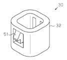
- the locking piece 51 extends in a hole formed in the side surface of the cylindrical portion 32 in a direction from the distal end of the cylindrical portion 32 toward the proximal end, and is connected to a portion near the distal end of the cylindrical portion 32. It can be elastically deformed with the base end of
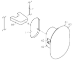
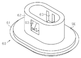
- a synthetic resin clip 60 may be fitted into the oval fitting hole H formed in the mounting portion 11. That is, the clip 60 has an oval head portion 61 and a cylindrical portion 62 having an oval cross section. The head 61 is joined to the peripheral edge of the fitting hole H on the inner side in the vehicle width direction of the attachment portion 11. The cylindrical portion 62 protrudes from the head 61 and has a shape that fits into the fitting hole H. A pair of locking claws 63 are formed on both side surfaces of the cylindrical portion 62. The locking claw 63 has substantially the same configuration as the locking claw 51 shown in FIG. The clip 60 is prevented from coming off from the fitting hole H (attachment portion 11) by the engaging claw 63 being engaged with the peripheral edge portion of the fitting hole H on the outer side in the vehicle width direction of the attachment portion 11.
- the garnish 7 has a flat boss 66 that is press-fitted into the cylindrical portion 62.
- the boss 66 is sandwiched between opposing wall portions in the short direction of the cylindrical portion 62 having an oval cross section.
- the lower part of the garnish 7 is attached to the rear frame part 5 b (lower part of the attachment part 11) via the clip 60 by press-fitting the boss 66 into the cylindrical part 62.
- the heat shrinkage of the garnish 7 can be absorbed by forming the cylindrical portion 62 and the fitting hole H of the clip 60 into an oval shape.
- the retaining claw 33 of the clip 30 may be provided on any one or more of the four side surfaces of the cylindrical portion 32.
- both corners of the cylindrical portion 32 arranged in the vehicle front-rear direction are sandwiched between a pair of ribs 21 arranged in the vehicle front-rear direction.
- the two corners of the cylindrical portion 32 aligned in the vehicle height direction are configured to be sandwiched by one rib aligned in the vehicle height direction. You may change direction and arrangement
- the present invention may be applied between the front frame portion 5a and the garnish 6. Moreover, you may apply to the front door as a vehicle door, for example.
- R circumferential surface, 1 ... vehicle door, 5 ... door frame, 5b ... rear frame portion, 7 ... garnish, 11 ... mounting portion, 12 ... fitting hole, 13 ... coupling hole, 21 ... rib, 22 ... side wall 23: Support wall part, 24 ... Locking groove, 25 ... Engagement wall part, 26 ... Locking protrusion, 30 ... Clip, 31 ... Head, 32 ... Tube part, 33 ... Locking claw, 40 ... Clip for coupling, 41... First head, 42... Second head, 44.
Landscapes
- Engineering & Computer Science (AREA)
- Mechanical Engineering (AREA)
- Vehicle Interior And Exterior Ornaments, Soundproofing, And Insulation (AREA)
- Connection Of Plates (AREA)
- Insertion Pins And Rivets (AREA)
- Clamps And Clips (AREA)
- Seal Device For Vehicle (AREA)
Abstract
Description
図4に示されるように、車両ドア1は、その下部を構成するドア本体2を備える。このドア本体2は、ドア外板を構成するドアアウタパネルとドア内板を構成するドアインナパネル(図示略)とが結合されてなる袋状の構造体であって、該ドア本体2の内部にはドア本体2の上部開口から出没可能なドアウインドガラスDW等が設置されている。
(1)本実施形態では、クリップ30は、係止爪33が嵌合孔12の周縁部に係止されることで該嵌合孔12(取付部11)から抜け止めされている。ガーニッシュ7は、嵌合孔12から車両幅方向外側に突出する筒部32の先端部を一対のリブ21にて挟持する。このようにして、ガーニッシュ7がクリップ30を介して後側フレーム部5bに取り付けられる。この場合、嵌合孔12は、頭部31にて覆われることで、嵌合孔12や同嵌合孔12の周辺部に付いた錆などが車両幅方向内側(車両ドア1の内側)に露出することがなく、見栄えを向上することができる。
なお、上記実施形態は以下のように変更してもよい。
図1(b)では、車両前後方向に並ぶ筒部32の両角部を、車両前後方向に並ぶ一対のリブ21で挟持するようにした。しかし、車両高さ方向に並ぶ筒部32の両角部を、車両高さ方向に並ぶ一つのリブで挟持するように構成する等、筒部32が嵌合される嵌合孔12及びリブ21の向きや配置を適宜変更してもよい。
Claims (5)
- 車両ドアの窓枠を構成するように適合されたドアフレームであって、1枚板で形成された取付部と、前記取付部を板厚方向に貫通する嵌合孔とを有し、前記嵌合孔が、その対角線が所定方向に一致する正方形状であるドアフレームと、
前記ドアフレームの前記取付部と対向して前記ドアフレームを車両幅方向外側から被覆するガーニッシュであって、前記対角線上における前記嵌合孔の一対の端部にそれぞれ対向して車両幅方向内側に向かって延びる一対のリブを有し、一対のリブは前記所定方向に間隔を隔てて互いに平行に配置される、前記ガーニッシュと、
前記嵌合孔に装着されるクリップであって、前記取付部の車両幅方向内側において前記嵌合孔の周縁部に接合される頭部と、前記頭部から突出して前記嵌合孔に嵌合する断面正方形状の筒部と、前記筒部の側面に設けられた係止爪とを有し、前記筒部は前記嵌合孔から前記取付部の車両幅方向外側に突出する先端部を有し、該先端部の前記所定方向に並ぶ一対の角部が前記一対のリブによって挟持され、前記係止爪は前記取付部の車両幅方向外側において前記嵌合孔の周縁部に係止される、前記クリップと
を有する、取付構造。 - 請求項1に記載の取付構造において、
前記筒部の4つの角部は、該筒部の中心線を中心とする円に一致する円周面として形成されている、取付構造。 - 請求項1又は2に記載の取付構造において、
前記ドアフレームは、前記取付部を板厚方向に貫通する結合孔を有し、
前記ガーニッシュは、
車両幅方向内側に向かって延びる一対の側壁部と、
前記一対の側壁部の先端同士を接続し、かつ前記結合孔に対向する支持壁部と、
前記支持壁部に形成され下側に開放された係止溝と、
前記一対の側壁部に沿って前記支持壁部から車両幅方向内側に向かって延びる一対の係合壁部と、
前記支持壁部の前記係止溝を挟んだ両側の下端部から車両幅方向内側に向かって延びる一対の係止突部とを有し、
前記取付構造はさらに、前記係止溝に装着される結合用クリップを備え、該結合用クリップは、
前記支持壁部の車両幅方向外側に配置される第1頭部と、
前記支持壁部の車両幅方向内側に配置され、前記第1頭部と共に前記係止溝の周縁部を挟持するとともに、前記一対の係合壁部及び前記一対の係止突部に嵌合する第2頭部と、
前記第2頭部から延出して前記結合孔に挿通され、前記取付部を挟んで前記第2頭部の反対側において前記結合孔の周縁部に係合する抜け止め部とを有する、取付構造。 - 請求項3に記載の取付構造において、
前記一対の係止突部は、前記第2頭部を前記一対の係合壁部及び前記一対の係止突部と嵌合する位置へ案内するガイド面をそれぞれ有する、取付構造。 - 請求項3又は4に記載の取付構造において、
前記結合用クリップは、前記係止溝に挿通されて前記第1及び第2頭部同士を接続する首部を有し、
前記支持壁部は、前記首部の下方への移動を規制する延出片を有する、取付構造。
Priority Applications (2)
| Application Number | Priority Date | Filing Date | Title |
|---|---|---|---|
| US13/138,438 US8640385B2 (en) | 2009-02-23 | 2010-02-22 | Trim attachment structure |
| CN201080008188.4A CN102317117B (zh) | 2009-02-23 | 2010-02-22 | 装饰物安装构造 |
Applications Claiming Priority (2)
| Application Number | Priority Date | Filing Date | Title |
|---|---|---|---|
| JP2009-039874 | 2009-02-23 | ||
| JP2009039874A JP5209534B2 (ja) | 2009-02-23 | 2009-02-23 | フレームガーニッシュ取付構造 |
Publications (1)
| Publication Number | Publication Date |
|---|---|
| WO2010095734A1 true WO2010095734A1 (ja) | 2010-08-26 |
Family
ID=42634009
Family Applications (1)
| Application Number | Title | Priority Date | Filing Date |
|---|---|---|---|
| PCT/JP2010/052601 Ceased WO2010095734A1 (ja) | 2009-02-23 | 2010-02-22 | ガーニッシュ取付構造 |
Country Status (5)
| Country | Link |
|---|---|
| US (1) | US8640385B2 (ja) |
| JP (1) | JP5209534B2 (ja) |
| CN (1) | CN102317117B (ja) |
| TW (1) | TWI449637B (ja) |
| WO (1) | WO2010095734A1 (ja) |
Cited By (2)
| Publication number | Priority date | Publication date | Assignee | Title |
|---|---|---|---|---|
| US8127501B2 (en) | 2007-04-17 | 2012-03-06 | Aisin Seiki Kabushiki Kaisha | Vehicle door having a garnish |
| CN109041576A (zh) * | 2015-08-25 | 2018-12-18 | 伯尔霍夫连接技术有限公司 | 用于连接组件的两件插入式联接器 |
Families Citing this family (57)
| Publication number | Priority date | Publication date | Assignee | Title |
|---|---|---|---|---|
| JP5061989B2 (ja) * | 2008-03-26 | 2012-10-31 | アイシン精機株式会社 | フレームガーニッシュの取付構造 |
| WO2010006266A1 (en) * | 2008-07-11 | 2010-01-14 | Cooper-Standard Automotive Inc. | Trim retainer/seal |
| JP5209534B2 (ja) | 2009-02-23 | 2013-06-12 | アイシン精機株式会社 | フレームガーニッシュ取付構造 |
| US9812684B2 (en) | 2010-11-09 | 2017-11-07 | GM Global Technology Operations LLC | Using elastic averaging for alignment of battery stack, fuel cell stack, or other vehicle assembly |
| DE102010061103A1 (de) * | 2010-12-08 | 2012-06-14 | Richard Fritz Gmbh + Co. Kg | Scheibeneinheit und Verfahren zu deren Herstellung |
| DE102011012256A1 (de) * | 2011-02-24 | 2012-08-30 | Daimler Ag | Fensterelement für eine Seitentür, insbesondere eine hintere Seitentür, eines Kraftwagens |
| JP2012206707A (ja) * | 2011-03-15 | 2012-10-25 | Asmo Co Ltd | 車両用ドアトリム及び車両用ドアトリムの製造方法 |
| US9061403B2 (en) | 2011-07-21 | 2015-06-23 | GM Global Technology Operations LLC | Elastic tube alignment system for precisely locating an emblem lens to an outer bezel |
| KR101231451B1 (ko) | 2011-09-20 | 2013-02-07 | 현대자동차주식회사 | 횡강성 강화타입 도어버티컬프레임 및 이를 적용한 프레임 도어 |
| JP2013124052A (ja) * | 2011-12-15 | 2013-06-24 | Nifco Inc | ガーニッシュクリップ |
| DE102012206934B4 (de) | 2012-04-26 | 2016-04-07 | Bayerische Motoren Werke Aktiengesellschaft | Bauteilverbindung |
| US9067379B2 (en) | 2012-04-28 | 2015-06-30 | GM Global Technologies Operations LLC | Stiffened multi-layer compartment door assembly utilizing elastic averaging |
| JP5948137B2 (ja) * | 2012-05-10 | 2016-07-06 | シロキ工業株式会社 | 車両用ドアフレーム |
| US9618026B2 (en) | 2012-08-06 | 2017-04-11 | GM Global Technology Operations LLC | Semi-circular alignment features of an elastic averaging alignment system |
| US9061715B2 (en) | 2012-08-09 | 2015-06-23 | GM Global Technology Operations LLC | Elastic cantilever beam alignment system for precisely aligning components |
| US9463538B2 (en) | 2012-08-13 | 2016-10-11 | GM Global Technology Operations LLC | Alignment system and method thereof |
| JP5872051B2 (ja) * | 2012-08-31 | 2016-03-01 | 本田技研工業株式会社 | 車両用ドア |
| FR2995829B1 (fr) * | 2012-09-25 | 2015-06-26 | Saint Gobain | Vitrage a joint profile encapsule et piece rapportee fixee au joint, element de fixation de la piece rapportee pour le vitrage et procede de fabrication du vitrage. |
| US9556890B2 (en) | 2013-01-31 | 2017-01-31 | GM Global Technology Operations LLC | Elastic alignment assembly for aligning mated components and method of reducing positional variation |
| US9156506B2 (en) | 2013-03-27 | 2015-10-13 | GM Global Technology Operations LLC | Elastically averaged alignment system |
| US9278642B2 (en) | 2013-04-04 | 2016-03-08 | GM Global Technology Operations LLC | Elastically deformable flange locator arrangement and method of reducing positional variation |
| US9388838B2 (en) | 2013-04-04 | 2016-07-12 | GM Global Technology Operations LLC | Elastic retaining assembly for matable components and method of assembling |
| US9382935B2 (en) | 2013-04-04 | 2016-07-05 | GM Global Technology Operations LLC | Elastic tubular attachment assembly for mating components and method of mating components |
| US9297400B2 (en) | 2013-04-08 | 2016-03-29 | GM Global Technology Operations LLC | Elastic mating assembly and method of elastically assembling matable components |
| US9067625B2 (en) | 2013-04-09 | 2015-06-30 | GM Global Technology Operations LLC | Elastic retaining arrangement for jointed components and method of reducing a gap between jointed components |
| US9447840B2 (en) | 2013-06-11 | 2016-09-20 | GM Global Technology Operations LLC | Elastically deformable energy management assembly and method of managing energy absorption |
| US9243655B2 (en) | 2013-06-13 | 2016-01-26 | GM Global Technology Operations LLC | Elastic attachment assembly and method of reducing positional variation and increasing stiffness |
| US9488205B2 (en) | 2013-07-12 | 2016-11-08 | GM Global Technology Operations LLC | Alignment arrangement for mated components and method |
| US9303667B2 (en) | 2013-07-18 | 2016-04-05 | Gm Global Technology Operations, Llc | Lobular elastic tube alignment system for providing precise four-way alignment of components |
| US9863454B2 (en) | 2013-08-07 | 2018-01-09 | GM Global Technology Operations LLC | Alignment system for providing precise alignment and retention of components of a sealable compartment |
| US9458876B2 (en) * | 2013-08-28 | 2016-10-04 | GM Global Technology Operations LLC | Elastically deformable alignment fastener and system |
| US9463831B2 (en) | 2013-09-09 | 2016-10-11 | GM Global Technology Operations LLC | Elastic tube alignment and fastening system for providing precise alignment and fastening of components |
| US9457845B2 (en) | 2013-10-02 | 2016-10-04 | GM Global Technology Operations LLC | Lobular elastic tube alignment and retention system for providing precise alignment of components |
| US9511802B2 (en) | 2013-10-03 | 2016-12-06 | GM Global Technology Operations LLC | Elastically averaged alignment systems and methods |
| US9669774B2 (en) | 2013-10-11 | 2017-06-06 | GM Global Technology Operations LLC | Reconfigurable vehicle interior assembly |
| US9481317B2 (en) | 2013-11-15 | 2016-11-01 | GM Global Technology Operations LLC | Elastically deformable clip and method |
| US9447806B2 (en) | 2013-12-12 | 2016-09-20 | GM Global Technology Operations LLC | Self-retaining alignment system for providing precise alignment and retention of components |
| US9428123B2 (en) | 2013-12-12 | 2016-08-30 | GM Global Technology Operations LLC | Alignment and retention system for a flexible assembly |
| US9216704B2 (en) | 2013-12-17 | 2015-12-22 | GM Global Technology Operations LLC | Elastically averaged strap systems and methods |
| US9599279B2 (en) | 2013-12-19 | 2017-03-21 | GM Global Technology Operations LLC | Elastically deformable module installation assembly |
| US9446722B2 (en) | 2013-12-19 | 2016-09-20 | GM Global Technology Operations LLC | Elastic averaging alignment member |
| US9238488B2 (en) | 2013-12-20 | 2016-01-19 | GM Global Technology Operations LLC | Elastically averaged alignment systems and methods |
| US9541113B2 (en) | 2014-01-09 | 2017-01-10 | GM Global Technology Operations LLC | Elastically averaged alignment systems and methods |
| US9463829B2 (en) | 2014-02-20 | 2016-10-11 | GM Global Technology Operations LLC | Elastically averaged alignment systems and methods |
| US9428046B2 (en) | 2014-04-02 | 2016-08-30 | GM Global Technology Operations LLC | Alignment and retention system for laterally slideably engageable mating components |
| US9429176B2 (en) | 2014-06-30 | 2016-08-30 | GM Global Technology Operations LLC | Elastically averaged alignment systems and methods |
| DE102015004982A1 (de) | 2015-04-18 | 2016-10-20 | GM Global Technology Operations LLC (n. d. Ges. d. Staates Delaware) | Befestigungsanordnung zum Positionieren und Befestigen einer Zierblende an einem Fensterrahmen einer Fahrzeugtür eines Fahrzeugs |
| JP6170535B2 (ja) * | 2015-10-22 | 2017-07-26 | 本田技研工業株式会社 | 自動車用ドア構造 |
| WO2017132382A1 (en) | 2016-01-26 | 2017-08-03 | Henniges Automotive Sealing Systems North America, Inc. | Method of manufacturing a seal assembly for a vehicle |
| US10029544B2 (en) | 2016-06-29 | 2018-07-24 | GM Global Technology Operations LLC | Glass run channel and applique attachment and method |
| JP6721497B2 (ja) * | 2016-12-12 | 2020-07-15 | アイシン精機株式会社 | ドアフレームガーニッシュ |
| JP6940767B2 (ja) * | 2017-10-12 | 2021-09-29 | テイ・エス テック株式会社 | 加飾部材 |
| US10723050B2 (en) | 2017-11-29 | 2020-07-28 | Henniges Automotive Sealing Systems North America, Inc. | Method of manufacturing a window seal assembly with a molded bracket |
| JP7145720B2 (ja) * | 2018-10-11 | 2022-10-03 | 西川ゴム工業株式会社 | ウェザストリップ |
| CN110979204A (zh) * | 2019-12-23 | 2020-04-10 | 重庆长安汽车股份有限公司 | 一种背门装饰亮条与后尾灯的连接结构 |
| FR3107936B1 (fr) * | 2020-03-05 | 2022-03-18 | Psa Automobiles Sa | Ensemble clipse comprenant un boitier fixe sur un support |
| FR3144787A1 (fr) * | 2023-01-06 | 2024-07-12 | Psa Automobiles Sa | Enjoliveur de cadre de porte pour véhicules automobiles |
Citations (3)
| Publication number | Priority date | Publication date | Assignee | Title |
|---|---|---|---|---|
| JP2004338522A (ja) * | 2003-05-15 | 2004-12-02 | Katayama Kogyo Co Ltd | 車両用ドアサッシュ |
| WO2008133115A1 (ja) * | 2007-04-17 | 2008-11-06 | Aisin Seiki Kabushiki Kaisha | 車両ドア |
| JP2009023630A (ja) * | 2007-07-24 | 2009-02-05 | Honda Motor Co Ltd | 車両のドアサッシュガーニッシュの組付部構造および組付方法 |
Family Cites Families (43)
| Publication number | Priority date | Publication date | Assignee | Title |
|---|---|---|---|---|
| JPS5929409U (ja) * | 1982-08-20 | 1984-02-23 | 株式会社ニフコ | 部品取付け用クリツプ |
| US4511129A (en) | 1982-10-25 | 1985-04-16 | Toyo Kogyo Co., Ltd. | Quarter-window structure for vehicle |
| US4927306A (en) * | 1988-05-18 | 1990-05-22 | Kato Hatsujo Kaisha, Ltd. | Screw grommet |
| JPH07122175B2 (ja) | 1988-07-12 | 1995-12-25 | 金井重要工業株式会社 | 紡機用回転リング |
| JPH0328052A (ja) | 1989-06-26 | 1991-02-06 | Nissan Motor Co Ltd | 自動車用フロントウインドウワイパー格納装置 |
| JPH03100514A (ja) | 1989-09-13 | 1991-04-25 | Fujitsu Ltd | ホログラムの作製方法 |
| JPH03107326A (ja) | 1989-09-19 | 1991-05-07 | Fujitsu General Ltd | 電源回路 |
| JP3107326B2 (ja) | 1992-04-13 | 2000-11-06 | 日本化薬株式会社 | 生理活性物質nk−04000p、nk−04000q、その製造法及びそれを有効成分として含有する除草剤 |
| JP2797910B2 (ja) | 1993-07-22 | 1998-09-17 | 日本鋼管株式会社 | 連続溶融めっき方法及びその方法に使用するドロス除去装置 |
| US5533237A (en) * | 1994-09-12 | 1996-07-09 | Emhart, Inc. | Grommet fastener assembly for automobiles |
| JP3100514B2 (ja) | 1994-10-14 | 2000-10-16 | 株式会社クボタ | カード式自動販売機 |
| DE19504692A1 (de) * | 1995-02-13 | 1996-08-14 | United Carr Gmbh Trw | Verbindung zwischen einem Träger und einem Plattenelement |
| US5968614A (en) | 1995-07-18 | 1999-10-19 | Decoma International Inc. | B-pillar covers for automotive vehicle |
| US5702148A (en) | 1996-02-29 | 1997-12-30 | The Standard Products Company | Exterior decorative surround molding module |
| JP3767164B2 (ja) | 1998-04-09 | 2006-04-19 | 日産自動車株式会社 | 自動車のドア構造 |
| US6141837A (en) * | 1999-02-26 | 2000-11-07 | Wisniewski; David M. | EDIAS clip for securing an interior molding to a vehicle frame |
| US6381811B2 (en) * | 2000-04-26 | 2002-05-07 | Termax Corporation | Sealing spring fastener with hermetically closed cavity |
| US6772484B2 (en) * | 2000-09-28 | 2004-08-10 | Toyoda Gosei Co., Ltd | Mounting structure for mounting a resin molded article to a body panel |
| CA2358824C (en) * | 2000-10-13 | 2005-06-28 | Hashimoto Forming Industry Company Limited | Automobile molding and fastener therefor |
| US6485049B1 (en) | 2000-12-21 | 2002-11-26 | Daimlerchrysler Corporation | Trim panel assembly for a motor vehicle |
| DE60202108T2 (de) | 2001-09-14 | 2005-12-01 | Toyoda Gosei Co., Ltd. | Dichtung für ein Fahrzeug |
| US7017239B2 (en) * | 2002-12-17 | 2006-03-28 | Illinois Tool Works Inc. | Component connection system |
| US6811194B1 (en) | 2003-07-03 | 2004-11-02 | Honda Giken Kogyo Kabushiki Kaisha | Garnish and seal assembly for a vehicle body portion, and method of attaching same |
| DE10349449B3 (de) * | 2003-10-23 | 2005-06-30 | Itw Automotive Products Gmbh & Co. Kg | Befestigungselement zur Verbindung eines Bauteils mit einem Trägerbauteil |
| JP4190409B2 (ja) * | 2003-12-26 | 2008-12-03 | 株式会社パイオラックス | クリップ |
| US7210730B2 (en) | 2004-02-26 | 2007-05-01 | Nishikawa Rubber Co., Ltd. | Mounting structure of automobile door |
| JP4598424B2 (ja) | 2004-03-25 | 2010-12-15 | アイシン精機株式会社 | 金属製スカッフプレート |
| FR2872556B1 (fr) * | 2004-07-02 | 2006-11-17 | I T W De France Soc Par Action | Agrafe pour la fixation d'un panneau a un support munie d'une tete comportant un membre deformable |
| US7461436B2 (en) * | 2004-10-26 | 2008-12-09 | Piolax, Inc. | Mounting structure of vehicle interior material |
| CA2575801C (en) | 2004-11-18 | 2014-01-28 | Cooper-Standard Automotive Inc. | Inner garnish assembly |
| US7356886B2 (en) * | 2005-04-14 | 2008-04-15 | Piolax, Inc. | Clamp |
| JP4345981B2 (ja) | 2005-11-24 | 2009-10-14 | 森六テクノロジー株式会社 | 一方の面を製品表面とした合成樹脂製品の連結構造 |
| JP2007302186A (ja) * | 2006-05-15 | 2007-11-22 | Katayama Kogyo Co Ltd | 車両用ドアフレーム |
| JP5000226B2 (ja) * | 2006-08-02 | 2012-08-15 | 大和化成工業株式会社 | クリップ |
| KR100892694B1 (ko) * | 2006-11-17 | 2009-04-15 | 현대자동차주식회사 | 차량용 도어 프레임 |
| DE202007002595U1 (de) * | 2007-02-22 | 2007-08-30 | Trw Automotive Electronics & Components Gmbh & Co. Kg | Befestigungsvorrichtung |
| CN201026847Y (zh) * | 2007-03-30 | 2008-02-27 | 重庆长安汽车股份有限公司 | 轿车顶盖装饰条卡子的安装结构 |
| US7927050B2 (en) * | 2007-05-30 | 2011-04-19 | Piolax Inc. | Interior part mounting clip |
| CN201102515Y (zh) * | 2007-07-12 | 2008-08-20 | 上汽通用五菱汽车股份有限公司 | 一种汽车装饰件的安装结构 |
| JP5210329B2 (ja) * | 2008-01-22 | 2013-06-12 | 株式会社パイオラックス | クリップ |
| JP5061989B2 (ja) | 2008-03-26 | 2012-10-31 | アイシン精機株式会社 | フレームガーニッシュの取付構造 |
| JP5209534B2 (ja) | 2009-02-23 | 2013-06-12 | アイシン精機株式会社 | フレームガーニッシュ取付構造 |
| JP5334176B2 (ja) * | 2009-03-06 | 2013-11-06 | 株式会社ニフコ | クリップ |
-
2009
- 2009-02-23 JP JP2009039874A patent/JP5209534B2/ja active Active
-
2010
- 2010-02-22 CN CN201080008188.4A patent/CN102317117B/zh not_active Expired - Fee Related
- 2010-02-22 US US13/138,438 patent/US8640385B2/en not_active Expired - Fee Related
- 2010-02-22 WO PCT/JP2010/052601 patent/WO2010095734A1/ja not_active Ceased
- 2010-02-23 TW TW099105166A patent/TWI449637B/zh not_active IP Right Cessation
Patent Citations (3)
| Publication number | Priority date | Publication date | Assignee | Title |
|---|---|---|---|---|
| JP2004338522A (ja) * | 2003-05-15 | 2004-12-02 | Katayama Kogyo Co Ltd | 車両用ドアサッシュ |
| WO2008133115A1 (ja) * | 2007-04-17 | 2008-11-06 | Aisin Seiki Kabushiki Kaisha | 車両ドア |
| JP2009023630A (ja) * | 2007-07-24 | 2009-02-05 | Honda Motor Co Ltd | 車両のドアサッシュガーニッシュの組付部構造および組付方法 |
Cited By (3)
| Publication number | Priority date | Publication date | Assignee | Title |
|---|---|---|---|---|
| US8127501B2 (en) | 2007-04-17 | 2012-03-06 | Aisin Seiki Kabushiki Kaisha | Vehicle door having a garnish |
| CN109041576A (zh) * | 2015-08-25 | 2018-12-18 | 伯尔霍夫连接技术有限公司 | 用于连接组件的两件插入式联接器 |
| US10746217B2 (en) | 2015-08-25 | 2020-08-18 | Böllhoff Verbindungstechnik GmbH | Two-part plug-in coupling for connecting components |
Also Published As
| Publication number | Publication date |
|---|---|
| JP5209534B2 (ja) | 2013-06-12 |
| US20110296764A1 (en) | 2011-12-08 |
| TWI449637B (zh) | 2014-08-21 |
| JP2010195106A (ja) | 2010-09-09 |
| TW201041766A (en) | 2010-12-01 |
| CN102317117A (zh) | 2012-01-11 |
| CN102317117B (zh) | 2014-03-12 |
| US8640385B2 (en) | 2014-02-04 |
Similar Documents
| Publication | Publication Date | Title |
|---|---|---|
| JP5209534B2 (ja) | フレームガーニッシュ取付構造 | |
| JP4869814B2 (ja) | ドアライニングの固定構造および固定方法 | |
| JP6401767B2 (ja) | 車体構造 | |
| WO2015152071A1 (ja) | 車両用モール | |
| JP4176795B2 (ja) | 窓ガラスとガラスモールの取付構造 | |
| JP2006097663A (ja) | エアクリーナのヒンジ機構 | |
| JP2013116680A (ja) | ドアフレームガーニッシュ取付構造 | |
| JP2017132399A (ja) | 車両用外装パネル | |
| JP4017718B2 (ja) | ルーフモール用クリップ | |
| JP2012206643A (ja) | ホールカバー取付構造 | |
| JP6597152B2 (ja) | 車両のドア開口部構造 | |
| KR102723472B1 (ko) | 문틀에 설치되는 보호덮개의 설치구조 | |
| CN113968129B (zh) | 发动机罩密封件 | |
| JP2004306685A (ja) | 車室内張り材の端末固定構造 | |
| JP2020125047A (ja) | 車両の車体側部構造 | |
| JP5381567B2 (ja) | 車両用ドアフレーム | |
| JP2010235092A (ja) | 自動車のドア | |
| JP2006192975A (ja) | カバー部材のフロントフェンダー取付部構造 | |
| JP2013244939A (ja) | ドアサッシュ及びサッシュモールディング | |
| JP2001088741A (ja) | 中空構造物の中空室遮断具 | |
| JP2518010Y2 (ja) | サイドプロテクタモール用シール取付け構造 | |
| JP6357868B2 (ja) | ベルトラインモールの取り付け部材 | |
| JPH0321291Y2 (ja) | ||
| JPS59223535A (ja) | ガ−ニツシユの取付構造 | |
| JPH0617609Y2 (ja) | ウエザストリツプ取付用クリツプ |
Legal Events
| Date | Code | Title | Description |
|---|---|---|---|
| WWE | Wipo information: entry into national phase |
Ref document number: 201080008188.4 Country of ref document: CN |
|
| 121 | Ep: the epo has been informed by wipo that ep was designated in this application |
Ref document number: 10743857 Country of ref document: EP Kind code of ref document: A1 |
|
| WWE | Wipo information: entry into national phase |
Ref document number: 13138438 Country of ref document: US |
|
| NENP | Non-entry into the national phase |
Ref country code: DE |
|
| 122 | Ep: pct application non-entry in european phase |
Ref document number: 10743857 Country of ref document: EP Kind code of ref document: A1 |