WO2010074008A1 - Procédé et dispositif permettant d'éliminer l'azote biologique et son support - Google Patents
Procédé et dispositif permettant d'éliminer l'azote biologique et son support Download PDFInfo
- Publication number
- WO2010074008A1 WO2010074008A1 PCT/JP2009/071181 JP2009071181W WO2010074008A1 WO 2010074008 A1 WO2010074008 A1 WO 2010074008A1 JP 2009071181 W JP2009071181 W JP 2009071181W WO 2010074008 A1 WO2010074008 A1 WO 2010074008A1
- Authority
- WO
- WIPO (PCT)
- Prior art keywords
- water
- nitrite
- treated
- reaction
- carrier
- Prior art date
Links
Images


Classifications
-
- C—CHEMISTRY; METALLURGY
- C02—TREATMENT OF WATER, WASTE WATER, SEWAGE, OR SLUDGE
- C02F—TREATMENT OF WATER, WASTE WATER, SEWAGE, OR SLUDGE
- C02F3/00—Biological treatment of water, waste water, or sewage
- C02F3/30—Aerobic and anaerobic processes
- C02F3/302—Nitrification and denitrification treatment
- C02F3/305—Nitrification and denitrification treatment characterised by the denitrification
-
- C—CHEMISTRY; METALLURGY
- C02—TREATMENT OF WATER, WASTE WATER, SEWAGE, OR SLUDGE
- C02F—TREATMENT OF WATER, WASTE WATER, SEWAGE, OR SLUDGE
- C02F3/00—Biological treatment of water, waste water, or sewage
- C02F3/30—Aerobic and anaerobic processes
- C02F3/302—Nitrification and denitrification treatment
-
- C—CHEMISTRY; METALLURGY
- C02—TREATMENT OF WATER, WASTE WATER, SEWAGE, OR SLUDGE
- C02F—TREATMENT OF WATER, WASTE WATER, SEWAGE, OR SLUDGE
- C02F3/00—Biological treatment of water, waste water, or sewage
- C02F3/006—Regulation methods for biological treatment
-
- C—CHEMISTRY; METALLURGY
- C02—TREATMENT OF WATER, WASTE WATER, SEWAGE, OR SLUDGE
- C02F—TREATMENT OF WATER, WASTE WATER, SEWAGE, OR SLUDGE
- C02F3/00—Biological treatment of water, waste water, or sewage
- C02F3/02—Aerobic processes
- C02F3/08—Aerobic processes using moving contact bodies
- C02F3/085—Fluidized beds
- C02F3/087—Floating beds with contact bodies having a lower density than water
-
- C—CHEMISTRY; METALLURGY
- C02—TREATMENT OF WATER, WASTE WATER, SEWAGE, OR SLUDGE
- C02F—TREATMENT OF WATER, WASTE WATER, SEWAGE, OR SLUDGE
- C02F3/00—Biological treatment of water, waste water, or sewage
- C02F3/02—Aerobic processes
- C02F3/10—Packings; Fillings; Grids
-
- C—CHEMISTRY; METALLURGY
- C02—TREATMENT OF WATER, WASTE WATER, SEWAGE, OR SLUDGE
- C02F—TREATMENT OF WATER, WASTE WATER, SEWAGE, OR SLUDGE
- C02F3/00—Biological treatment of water, waste water, or sewage
- C02F3/02—Aerobic processes
- C02F3/10—Packings; Fillings; Grids
- C02F3/109—Characterized by the shape
-
- C—CHEMISTRY; METALLURGY
- C02—TREATMENT OF WATER, WASTE WATER, SEWAGE, OR SLUDGE
- C02F—TREATMENT OF WATER, WASTE WATER, SEWAGE, OR SLUDGE
- C02F3/00—Biological treatment of water, waste water, or sewage
- C02F3/28—Anaerobic digestion processes
- C02F3/2813—Anaerobic digestion processes using anaerobic contact processes
-
- C—CHEMISTRY; METALLURGY
- C02—TREATMENT OF WATER, WASTE WATER, SEWAGE, OR SLUDGE
- C02F—TREATMENT OF WATER, WASTE WATER, SEWAGE, OR SLUDGE
- C02F3/00—Biological treatment of water, waste water, or sewage
- C02F3/34—Biological treatment of water, waste water, or sewage characterised by the microorganisms used
- C02F3/341—Consortia of bacteria
-
- C—CHEMISTRY; METALLURGY
- C02—TREATMENT OF WATER, WASTE WATER, SEWAGE, OR SLUDGE
- C02F—TREATMENT OF WATER, WASTE WATER, SEWAGE, OR SLUDGE
- C02F3/00—Biological treatment of water, waste water, or sewage
- C02F3/34—Biological treatment of water, waste water, or sewage characterised by the microorganisms used
- C02F3/348—Biological treatment of water, waste water, or sewage characterised by the microorganisms used characterised by the way or the form in which the microorganisms are added or dosed
-
- C—CHEMISTRY; METALLURGY
- C02—TREATMENT OF WATER, WASTE WATER, SEWAGE, OR SLUDGE
- C02F—TREATMENT OF WATER, WASTE WATER, SEWAGE, OR SLUDGE
- C02F2209/00—Controlling or monitoring parameters in water treatment
- C02F2209/02—Temperature
-
- C—CHEMISTRY; METALLURGY
- C02—TREATMENT OF WATER, WASTE WATER, SEWAGE, OR SLUDGE
- C02F—TREATMENT OF WATER, WASTE WATER, SEWAGE, OR SLUDGE
- C02F2209/00—Controlling or monitoring parameters in water treatment
- C02F2209/04—Oxidation reduction potential [ORP]
-
- C—CHEMISTRY; METALLURGY
- C02—TREATMENT OF WATER, WASTE WATER, SEWAGE, OR SLUDGE
- C02F—TREATMENT OF WATER, WASTE WATER, SEWAGE, OR SLUDGE
- C02F2209/00—Controlling or monitoring parameters in water treatment
- C02F2209/06—Controlling or monitoring parameters in water treatment pH
-
- C—CHEMISTRY; METALLURGY
- C02—TREATMENT OF WATER, WASTE WATER, SEWAGE, OR SLUDGE
- C02F—TREATMENT OF WATER, WASTE WATER, SEWAGE, OR SLUDGE
- C02F2209/00—Controlling or monitoring parameters in water treatment
- C02F2209/15—N03-N
-
- C—CHEMISTRY; METALLURGY
- C02—TREATMENT OF WATER, WASTE WATER, SEWAGE, OR SLUDGE
- C02F—TREATMENT OF WATER, WASTE WATER, SEWAGE, OR SLUDGE
- C02F2209/00—Controlling or monitoring parameters in water treatment
- C02F2209/16—Total nitrogen (tkN-N)
-
- C—CHEMISTRY; METALLURGY
- C02—TREATMENT OF WATER, WASTE WATER, SEWAGE, OR SLUDGE
- C02F—TREATMENT OF WATER, WASTE WATER, SEWAGE, OR SLUDGE
- C02F2209/00—Controlling or monitoring parameters in water treatment
- C02F2209/18—PO4-P
-
- C—CHEMISTRY; METALLURGY
- C02—TREATMENT OF WATER, WASTE WATER, SEWAGE, OR SLUDGE
- C02F—TREATMENT OF WATER, WASTE WATER, SEWAGE, OR SLUDGE
- C02F2209/00—Controlling or monitoring parameters in water treatment
- C02F2209/22—O2
-
- Y—GENERAL TAGGING OF NEW TECHNOLOGICAL DEVELOPMENTS; GENERAL TAGGING OF CROSS-SECTIONAL TECHNOLOGIES SPANNING OVER SEVERAL SECTIONS OF THE IPC; TECHNICAL SUBJECTS COVERED BY FORMER USPC CROSS-REFERENCE ART COLLECTIONS [XRACs] AND DIGESTS
- Y02—TECHNOLOGIES OR APPLICATIONS FOR MITIGATION OR ADAPTATION AGAINST CLIMATE CHANGE
- Y02W—CLIMATE CHANGE MITIGATION TECHNOLOGIES RELATED TO WASTEWATER TREATMENT OR WASTE MANAGEMENT
- Y02W10/00—Technologies for wastewater treatment
- Y02W10/10—Biological treatment of water, waste water, or sewage
Definitions
- the present invention relates to a biological nitrogen removal method and nitrogen removal apparatus using an anaerobic ammonia oxidation reaction for water to be treated containing soluble nitrogen such as ammonia nitrogen, and water treatment provided with the nitrogen removal apparatus. More specifically, the system, and the biological nitrogen-removing method and the carrier for supporting bacteria used in the nitrogen-removing device, more specifically, ammoniacal nitrogen concentration of water to be treated, water temperature in the reaction tank, Biological nitrogen removing method and nitrogen removing device capable of denitrification at a practical level while relaxing restrictions on DO value and pH value, water treatment system equipped with nitrogen removing device, and biological The present invention relates to a method for removing nitrogen and a carrier for supporting bacteria used in the nitrogen removing apparatus.
- a denitrification technique using microbial bacteria has been used for water to be treated containing ammoniacal nitrogen, for example, sewage.
- This biological nitrogen removal technology converts ammonia nitrogen in water to be treated into nitrogen gas through a two-stage biological reaction, nitrification and denitrification, and discharges it out of the system.
- ammonia nitrogen is removed. Is oxidized to nitrite nitrogen using oxygen by an ammonia-oxidizing bacterium under aerobic conditions, and then the nitrite nitrogen is oxidized to nitrate nitrogen by a nitrite-oxidizing bacterium.
- Nitrate nitrogen and nitrate nitrogen are converted into nitrogen gas by denitrifying bacteria under anoxic conditions while using organic substances as electron donors.
- the anaerobic ammonia oxidation reaction is a biological reaction using anaerobic ammonia oxidizing bacteria. Under anaerobic conditions, anaerobic ammonia oxidizing bacteria convert ammonia nitrogen to an electron donor and nitrite nitrogen to electrons.
- This is a group of denitrifying microorganisms that can react with each other as an acceptor to generate nitrogen gas, and are denitrifying microorganisms that do not require the addition of organic substances during denitrification.
- nitrite nitrogen and ammonia nitrogen in the treated water in the partial nitrification tank are reacted to convert them into nitrogen gas, and the pH adjustment tank uses the treated water in the denitrification tank partially.
- the pH is adjusted by circulation to a nitritation tank.
- a partial nitrification tank, a pH adjustment tank, and a denitrification tank are separately provided, and in each of the partial nitrification tank and the denitrification tank, partial nitrification is performed. Since it is necessary to adjust the pH value required for the reaction and the pH value required for the denitrification reaction, the equipment cost is high as a biological nitrogen removal device, and the biological nitrogen removal method is a simple method. I could't say.
- Patent Document 2 discloses a biological nitrogen removal apparatus and biological nitrogen removal method using an anaerobic ammonia oxidation reaction that solves such technical problems.
- This biological nitrogen removal apparatus uses a partial nitrification tank and a denitrification tank as a single tank, and in this single tank, a partial nitrification reaction and a denitrification reaction are not required without adjusting the pH value.
- a partial nitrification reaction and a denitrification reaction are not required without adjusting the pH value.
- nitrite-type nitrifying bacteria contributing to nitrite-type nitrification reaction are predominated as an anaerobic ammonia-oxidizing bacteria.
- the biological nitrogen removal method using this anaerobic ammonia oxidation reaction has the following technical problems. That is, due to restrictions on the ammonia nitrogen concentration of the water to be treated, the water temperature in the reaction tank, the DO value, and the pH value, the treatment water containing ammonia nitrogen is unconditionally biological This is not to be able to perform nitrogen removal.
- nitrite type nitrifying bacteria that contribute to nitrite type nitrification reaction are dominant species and contribute to anaerobic ammonia oxidation reaction
- An anaerobic ammonia-oxidizing bacterium that predominates is placed in a form surrounded by the nitrite-type nitrifying bacterium, and a carrier carrying two layers of microbial membranes on the surface is disposed on the inside, thereby predominating species
- Nitrite is produced by causing a nitrite-type nitrification reaction (1) by the nitrite-type nitrifying bacteria present on the outside.
- nitric acid is further oxidized by nitric acid-type nitrifying bacteria as shown in the following reaction formula to produce nitric acid. Will be.
- Nitric acid type nitrification reaction NO 2 ⁇ + 0.5O 2 ⁇ NO 3 ⁇ + H 2 O + 2H + Therefore, in order to implement a biological nitrogen removal method using an anaerobic ammonia oxidation reaction at a practical level, while increasing the amount of nitrous acid produced by the nitrite type nitrification reaction (1), It is necessary to secure ammonia nitrogen and nitrite nitrogen necessary for the anaerobic ammonia oxidation reaction (2) by inhibiting the nitrate nitrification reaction (3).
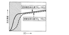
- FIGS. 8 to 11 show the temperature of treated water, DO (dissolved oxygen amount) in treated water, and the treated water in relation to the growth rate or reaction rate of nitrite-type nitrifying bacteria and nitrate-type nitrifying bacteria, respectively. It is the graph which showed typically the influence which ammonia nitrogen concentration and the pH of to-be-processed water give.
- the higher the temperature of the water to be treated the higher the growth rate of the nitrite type nitrifying bacteria compared to the nitrate type nitrifying bacteria. Therefore, the temperature of the water to be treated is preferably high.
- DO dissolved oxygen amount
- the lower the DO (dissolved oxygen amount) in the water to be treated the lower the reaction rate of nitrate nitrifying bacteria compared to the nitrite type nitrifying bacteria.
- the aerobic condition it is preferably low.
- the higher the ammonia nitrogen concentration in the treated water the lower the reaction rate of the nitrate nitrifying bacteria compared to the nitrite type nitrifying bacteria. Is preferably high.
- the higher the pH of the water to be treated the lower the growth rate of nitrate-type nitrifying bacteria compared to nitrite-type nitrifying bacteria. Therefore, the pH of the water to be treated is high. preferable.
- nitrite type nitrification that contributes to nitrite type nitrification reaction in treated water containing dissolved nitrogen, which has flowed into the reaction vessel under aerobic conditions.
- Anaerobic that contributes to anaerobic ammonia oxidation reaction on the outside with bacteria or aerobic bacteria that decompose soluble nitrogen other than ammonia as ammonia and nitrite-type nitrifying bacteria that contribute to nitrite-type nitrifying reaction Anaerobic ammonia oxidation reaction by flowing a carrier carrying two layers of microbial membranes on the inside in a form surrounded by nitrite-type nitrifying bacteria as a dominant species of oxidative ammonia-oxidizing bacteria
- a biological nitrogen removal method using an anaerobic ammonia oxidation reaction is provided that adjusts the carrier input rate (total surface area of the carrier per unit volume of the reaction
- nitrite-type nitrifying bacteria that contribute to the nitrite-type nitrification reaction in the treated water containing soluble nitrogen, which has been flowed into the reaction tank under aerobic conditions, or other than ammonia Aerobic bacteria that decompose ammonia in nitrous acid and nitrite-type nitrifying bacteria that contribute to nitrite-type nitrification reaction as dominant species, and anaerobic ammonia-oxidizing bacteria that contribute to anaerobic ammonia oxidation reaction As an occupying species, it is surrounded by the nitrite-type nitrifying bacteria, and a carrier carrying two layers of microbial membranes on the surface is flowed inside.
- a biological nitrogen removal method using an anaerobic ammonia oxidation reaction that denitrifies from water, and the amount of nitrous acid produced by the nitrite type nitrification reaction of the nitrite type nitrifying bacteria Deter As a level enough to adjust the flow rate of the water to be treated to the carrier surface, the biological nitrogen removal method utilizing anaerobic ammonium oxidation is provided.
- nitrite-type nitrifying bacteria that contribute to the nitrite-type nitrification reaction or other than ammonia in the treated water containing soluble nitrogen that has flowed into the reaction vessel under aerobic conditions Aerobic bacteria that decompose ammonia in nitrous acid and nitrite-type nitrifying bacteria that contribute to nitrite-type nitrification reaction as dominant species, and anaerobic ammonia-oxidizing bacteria that contribute to anaerobic ammonia oxidation reaction As an occupying species, it is surrounded by the nitrite-type nitrifying bacteria, and a carrier carrying two layers of microbial membranes on the surface is flowed inside.
- a biological nitrogen removal method using an anaerobic ammonia oxidation reaction that denitrifies from water, and the amount of nitrous acid produced by the nitrite type nitrification reaction of the nitrite type nitrifying bacteria Deterrence Biological nitrogen removal using an anaerobic ammonia oxidation reaction that adjusts the carrier input rate (total surface area of the carrier per unit volume of the reaction tank) and the flow rate of water to be treated with respect to the surface of the carrier so A method is provided.
- the biological nitrogen removal method according to the present invention pays attention to the carrier input rate in the water to be treated and / or the flow rate of the water to be treated on the surface of the carrier, and appropriately adjusts these to treat the target to be treated. Denitrification is made possible at a practical level using an anaerobic ammonia oxidation reaction while relaxing restrictions on the ammoniacal nitrogen concentration of water, the water temperature in the reaction tank, the DO value, and the pH value. More specifically, in the biological nitrogen removal method according to the present invention, the nitric acid type, which is the reaction of (3), is adjusted by adjusting the carrier input rate in the treated water and / or the flow rate of the treated water relative to the surface of the carrier.
- the amount of nitrous acid produced by the nitrite-type nitrification reaction (1) is increased to reduce the amount of ammonia nitrogen necessary for the anaerobic ammonia oxidation reaction (2). It secures nitrite nitrogen.
- the biological nitrogen removal method according to the present invention is performed by the following process.
- the carrier charging rate is adjusted based on the soluble nitrogen concentration in the water to be treated.
- the carrier charging rate is the total surface area of the carrier per unit volume of the reaction tank.
- the carrier input rate is reduced when the concentration of soluble nitrogen in the water to be treated is low.
- the carrier is caused to flow so as to be uniformly distributed in the reaction vessel. Thereby, it is possible to ensure the ammonia load per unit time and the surface area of the support uniformly throughout the entire reaction tank.
- a nitrite type nitrification reaction is caused by the nitrite type nitrifying bacteria located outside as the dominant species of the surface portion of each carrier.
- the carrier input rate is reduced as described above, the unit of the carrier
- the ammonia load per surface area increases, and as a result, the number of nitrite-type nitrifiers per unit surface area of the carrier increases due to the growth of nitrite-type nitrifiers that contribute to the nitrite-type nitrification reaction.
- the film thickness of the outer microbial membrane with nitrifying bacteria as the dominant species increases, and the removal rate of ammonia nitrogen per carrier surface area increases.
- the flow rate of the water to be treated on the surface of the carrier is adjusted. For example, when the concentration of dissolved nitrogen in the water to be treated is low, the flow rate of the water to be treated on the surface of the carrier is increased. When the flow rate of water to be treated on the surface of the carrier is increased in this way, the rate at which ammonium ions can move from the liquid phase per unit surface area of the carrier to the microbial membrane increases, and as a result, contributes to the nitrite type nitrification reaction.
- nitrite-type nitrifying bacteria increases the number of nitrite-type nitrifying bacteria per unit surface area of the carrier, increasing the film thickness of the outer microbial membrane with nitrite-type nitrifying bacteria as the dominant species, and ammonium. It is possible to ensure a nitrogen removal rate commensurate with the ion movement rate.
- the film thickness of the microbial film having nitrite type nitrifying bacteria as the dominant species is increased, and nitrite type nitrification reaction is caused.
- the amount of nitrous acid increases and the amount of nitrous acid generated by the reaction reaches a level that inhibits the nitric acid-type nitrification reaction, the generated nitrous acid is not converted to nitric acid, and is necessary for the anaerobic ammonia oxidation reaction. It becomes possible to secure nitrous acid.
- FIGS. 12A to 12C show how the ammonia nitrogen concentration, nitrite nitrogen concentration, nitrate nitrogen concentration and nitrogen gas concentration change along with the DO value in the surface of the carrier toward the inside of the carrier.
- FIG. 12A schematically illustrates an initial biological nitrogen removal technique that requires a large amount of oxygen
- FIG. 12B illustrates a conventional biological nitrogen removal technique that utilizes an anaerobic ammonia oxidation reaction
- FIG. 12C shows a biological nitrogen removal technique using an anaerobic ammonia oxidation reaction according to the present invention.
- the horizontal length of the rectangular portion means the film thickness of the microbial membrane supported on the surface portion of the carrier, and the left side in the drawing is the surface portion of the microbial membrane.
- the vertical length of the rectangular portion indicates the ammonia nitrogen concentration, the nitrite nitrogen concentration, the nitrate nitrogen concentration, and the nitrogen concentration.
- the concentration of nitrite nitrogen is higher than the concentration of ammonia nitrogen, and further toward the inside of the membrane, the concentration of nitrate nitrogen and nitrogen increases, while the concentration of ammonia nitrogen and nitrite nitrogen decreases. is doing.
- FIG. 12A the nitrate nitrogen concentration starts to increase from the surface of the microbial membrane, and after the ammonia nitrogen concentration becomes zero, the nitrate nitrogen concentration occupies the whole.
- FIGS. 12B and 12C the nitrite nitrogen concentration and the ammonia nitrogen concentration are secured at the position where the DO value becomes zero, thereby causing an anaerobic ammonia oxidation reaction under anaerobic conditions.
- the nitrogen concentration increases with the nitrate nitrogen concentration.
- the carrier input rate and / or the flow rate of water to be treated with respect to the carrier surface can be adjusted. Due to the difference in the thickness of the microbial membrane due to the above, the nitrite nitrogen concentration is higher in FIG. 12C where the microbial membrane is thicker, thereby suppressing the subsequent nitric acid-type nitrification reaction.
- the carrier input rate so that the inflow soluble nitrogen load is 4.0 to 11.5 g / m 2 carrier / day. Further, it is preferable to adjust the specific carrier loading rate to 4 to 40 m 2 / m 3 .
- stirring a to-be-processed water so that the maximum flow rate of the to-be-processed water in a reaction tank may be 0.7 m / sec or more. Further, the present invention is preferably carried out in a state where the ORP (redox potential) of the water to be treated is ⁇ 150 mV or less, and more preferably in the state where it is ⁇ 300 mV or less.
- the water to be treated containing soluble nitrogen to be treated according to the present invention may be waste water having a normal temperature and a soluble nitrogen concentration of 50 mg / L or less.
- a nitrite type nitrification reaction Surrounded by bacteria and aerobic bacteria that decompose soluble nitrogen other than ammonia into ammonia and nitrite type nitrifying bacteria that contribute to nitrite type nitrification reaction as dominant species and the nitrite type nitrifying bacteria
- an anaerobic ammonia-oxidizing bacterium is predominated as a dominant species, and a carrier having a two-layer microbial membrane supported on the inside is disposed on the surface, and the carrier is flowed in the water to be treated.
- a biological nitrogen removing apparatus utilizing an anaerobic ammonia oxidation reaction comprising: a fluidizing means that is disposed in the reaction tank; and an aeration means that supplies oxygen to the water to be treated.
- a fluidizing means that is disposed in the reaction tank
- an aeration means that supplies oxygen to the water to be treated.
- an agitation device that has an agitation power capable of adjusting the rate of movement of ammonia ions per unit surface area of the membrane to the microorganism membrane by adjusting the flow rate of water to be treated on the surface.
- a nitrogen removal device is provided.
- the ammonia ion transfer rate per unit surface area of the membrane to the microorganism membrane can be adjusted by adjusting the flow rate of the water to be treated on the surface of the carrier.
- nitrite by nitrite-type nitrification reaction of nitrite-type nitrifying bacteria existing as dominant species in the outer layer of the two-layer microbial membranes supported on the surface of the carrier It is possible to secure the ammonia nitrogen and nitrite nitrogen necessary for the anaerobic ammonia oxidation reaction.
- the stirring device may be a draft air tube aerator.
- the biological nitrogen removing apparatus of the present invention and the upstream side of the reaction tank of the biological nitrogen removing apparatus are installed in the solid organic matter from the water to be treated.
- a flocculant adding means for adding a flocculant for aggregating solid organic matter and / or phosphorus in the water to be treated biologically nitrogen-removed in the reaction tank, Water treatment of water to be treated containing soluble nitrogen, having a second settling tank installed downstream of the reaction tank and precipitating solid organic matter and / or phosphorus aggregated by the flocculant addition means
- a system (first water treatment system) is provided.
- the biological nitrogen removing apparatus of the present invention a flocculant addition means for adding a flocculant for aggregating solid organic matter and / or phosphorus in the water to be treated,
- a first precipitation tank installed upstream of the reaction tank of the biological nitrogen removal apparatus of the present invention, for precipitating solid organic matter and / or phosphorus aggregated by the flocculant addition means; and downstream of the reaction tank
- a water treatment system (second water treatment system) for water to be treated containing soluble nitrogen, which has a second settling tank for precipitating solid matter.
- the water treatment system having the above configuration, by performing denitrification using an anaerobic ammonia oxidation reaction, it is possible to reduce the amount of oxygen necessary to denitrify the water to be treated. Because denitrification uses a carrier carrying bacteria instead of activated sludge, there is no need for equipment to return activated sludge to the reaction tank, and at the same time, solidity that is inevitably mixed in activated sludge. When the organic matter is decomposed, oxygen is not consumed, and the amount of oxygen necessary for water treatment of the water to be treated containing ammonia nitrogen can be significantly reduced as a whole.
- the first water treatment system and the second water treatment system are common in that they have the biological nitrogen removal apparatus of the present invention.
- biological reaction is performed in the reaction tank.
- the flocculant is added to the water to be treated after the nitrogen has been removed by the flocculant adding means, and the solid organic matter and / or phosphorus aggregated in the second settling tank downstream of the reaction tank.
- the flocculant is added by the flocculant adding means to the water to be treated before being biologically nitrogen-removed in the reaction tank.
- the first and second precipitation tanks are different from each other in that they are configured to precipitate the aggregated solid organic matter and / or phosphorus in the first precipitation tank on the upstream side.
- an aerobic bacterium that contributes to a nitrite type nitrification reaction, or an aerobic bacterium that decomposes soluble nitrogen other than ammonia into ammonia and nitrite type nitrification
- Two layers of microbial membranes that have nitrite type nitrifying bacteria contributing to the reaction on the outside as dominant species, and anaerobic ammonia oxidizing bacteria in the form surrounded by the nitrite type nitrifying bacteria on the inside as dominant species
- the carrier is supported on the surface, and is desorbed from the treated water using an anaerobic ammonia oxidation reaction by flowing the carrier in the treated water containing soluble nitrogen under aerobic conditions.
- a carrier capable of denitrifying from water to be treated using an anaerobic ammonia oxidation reaction having excellent strength characteristics is provided.
- the carrier having the above-described configuration, the amount of nitrite produced by the nitrite-type nitrification reaction of the nitrite-type nitrifier becomes such a level that the nitrate-type nitrification reaction is suppressed.
- the thickness of the microbial membrane increases, it has water absorption properties and / or hydrophilic properties capable of supporting the microbial membrane of such thickness, and by increasing the flow rate of water to be treated on the surface of the carrier, When increasing the transfer rate of ammonium ions from the liquid phase per unit surface area to the microbial membrane, the carrier has strength characteristics to withstand the shearing force acting on the carrier by flowing in the treated water.
- the anaerobic ammonia oxidation reaction can be used while relaxing the restrictions on the ammoniacal nitrogen concentration of the water to be treated, the water temperature in the reaction tank, the DO value, and the pH value. To, it is possible to perform denitrification with de ⁇ rate practical level.
- the carrier is preferably made of a water-absorbing polyurethane resin mainly composed of a hydrophilic TPU resin. Moreover, it is preferable that a crosslinking agent which is a hydrophobic prepolymer is added to the carrier.
- the ammonia nitrogen concentration of the water to be treated As described above, conventionally, the ammonia nitrogen concentration of the water to be treated, the water temperature in the reaction tank, the DO value for the promotion of the nitrite type nitrification reaction and the suppression of the nitrate type nitrification reaction
- the production of nitrous acid contributes to the inhibition of the nitric acid type nitrification reaction, thereby promoting the nitrite type nitrification reaction.
- Example 1 of the present invention the dissolved nitrogen concentration of the reaction vessel influent water, the NH 4 -N concentration of the reaction vessel inflow water, the soluble nitrogen concentration of the reaction vessel effluent water, and the NH 4 -N concentration of the reaction vessel effluent water, respectively. It is a graph which shows the time change of.
- Example 2 of the present invention when the carrier input ratio of 90m 2 carriers total surface area / m 3 tank volume, ionic nitrogen concentration, a graph showing the NO X -N concentration and NH 4 -N concentration each time change is there.
- the carrier input ratio when the carrier input ratio is 30 m 2 support the total surface area / m 3 tank volume, ionic nitrogen concentration, a graph showing the NO X -N concentration and NH 4 -N concentration each time change is there.
- the time change of each of ionic nitrogen concentration, NO x -N concentration and NH 4 -N concentration when the carrier loading rate is 7.5 m 2 total surface area / m 3 tank volume is shown. It is a graph.
- nitrification is performed by ammonia oxidizing bacteria and nitrite oxidizing bacteria Indicates.
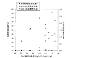
- Soluble nitrogen removal rate, NO 2 -N product concentration and NO 3 -N product concentration is a graph showing how the changes by the ratio of DO on solubility nitrogen load.
- 3 is a graph showing how soluble nitrogen removal rate, NO 2 —N production concentration and NO 3 —N production concentration vary with the ratio of DO to soluble total organic carbon load. It is the schematic which shows an example of the adjustment method of the aeration amount in a reaction tank.
- FIG. 6 is a graph showing how the dissolved nitrogen removal rate and NO 3 —N production concentration change with the influent dissolved nitrogen load. It is a graph which shows how a soluble nitrogen removal rate changes with the oxidation-reduction potential of reaction tank inflow water.
- FIG. 3 is a flow chart when nitrogen removal is performed by the biological nitrogen removal method of the present invention, and soluble organic matter and phosphorus are removed using activated sludge.
- the water treatment system 10 includes a first precipitation tank 12, a reaction tank 14, a mixing tank 16, and a second precipitation from the upstream side to the downstream side of the water to be treated.
- a tank 18, a DO meter 20 and a PO 4 meter 22, and a flocculant injection pump 24 are roughly configured.
- the water to be treated that can be treated in the present invention is a nitrogen-containing liquid containing soluble nitrogen, and may contain ammonia nitrogen, nitrite nitrogen, organic nitrogen, and other nitrogen, Sewage, human waste, food wastewater, factory wastewater, and other industrial wastewater.
- the present invention uses an anaerobic ammonia oxidation reaction at a practical level while relaxing restrictions on the ammoniacal nitrogen concentration of the water to be treated, the water temperature in the reaction tank, the DO value and the pH value. Nitrogen can be produced, and can be applied to, for example, city sewage and domestic wastewater having a low nitrogen concentration at room temperature and a soluble nitrogen concentration of 50 mg / L or less.
- the first settling tank 12 is provided for precipitating and removing solids from the water to be treated which has flowed into the tank, and the supernatant liquid in the tank is connected to the downstream reaction tank 14 through a connecting pipe. It is made to flow into.
- the sludge accumulated at the bottom of the first sedimentation tank 12 is periodically removed from the first sedimentation tank 12, sent to a sludge treatment facility, and disposed of as it is.
- the reaction tank 14 is a single tank, the inside of which is divided into three through the partition wall 30, and the three divided parts communicate with each other.
- a nitrification tank that performs a nitrite-type nitrification reaction and an anaerobic ammonia oxidation tank that performs an anaerobic ammonia oxidation reaction are provided separately.
- ammonia nitrogen in the treated water under aerobic conditions Nitrification process to oxidize nitrite nitrogen to the nitrite nitrogen by the action of ammonia oxidizing bacteria.
- nitrite nitrogen is used as an electron acceptor, and remaining ammonia nitrogen is used as an electron donor.
- the anaerobic ammonia oxidation reaction step for generating nitrogen gas by the above action is performed, and these aerobic nitrification step and anaerobic ammonia oxidation reaction step are performed in a single tank.
- a carrier 26 that carries bacteria is introduced, and an aeration device is installed.
- an aeration device is installed in the reaction tank 14, and an aeration device is installed.
- the carrier 26 which carries a microbe in the to-be-processed water is made to flow, and it is made to distribute uniformly in to-be-processed water.
- the carrier 26 is a granular resin carrier, and the size and shape of the carrier 26 are arbitrary as long as the carrier 26 can retain bacteria even when the carrier 26 flows in the water to be treated. is there.
- it may be a cylindrical shape, a spherical shape, or the like with an outer dimension of about several millimeters.
- the nitrite type nitrification zone on the surface of the carrier 26 mainly carries nitrite type nitrification bacteria, and the anaerobic ammonia oxidation reaction zone mainly carries anaerobic ammonia oxidation reaction bacteria. I am doing so.
- an aerobic bacterium that decomposes soluble nitrogen other than ammonia to form ammonia may be supported in the nitrite-type nitrification zone.
- the carrier 26 is aerobic bacteria that decompose nitrite-type nitrifying bacteria that contribute to the nitrite-type nitrification reaction, or decompose dissolved nitrogen other than ammonia into ammonia and nitrous acid-type nitrifying reactions that contribute to the nitrite-type nitrification reaction.
- a microbial membrane is supported on the surface.
- an aerobic bacterium that decomposes soluble nitrogen other than ammonia into ammonia in addition to nitrite type nitrifying bacteria is supported on the outer layer of the two-layer microbial membrane, soluble nitrogen other than ammonia is supported. After being decomposed into ammonia by the aerobic bacterium, it is subjected to a nitrite type nitrification reaction by a nitrite type nitrifying bacterium.
- aerobic bacteria which decompose soluble nitrogen other than ammonia into ammonia include bacteria belonging to the genus Bacillus.
- the material of the carrier 26 has strength characteristics that can withstand the shearing force acting on the surface portion of each carrier 26 due to the strong stirring force by the air diffuser, and to be processed. While each carrier 26 flows in water, it is necessary to have water absorption or hydrophilicity capable of holding nitrite type nitrifying bacteria and anaerobic ammonia oxidation reaction bacteria on the surface portion.
- the charge rate is adjusted in accordance with the dissolved nitrogen concentration, so that a microbial membrane having a nitrite-type nitrifying bacterium existing on the surface of the carrier 26 as a dominant species can be obtained.
- the film thickness is increased, it is necessary to have characteristics capable of retaining nitrite-type nitrifying bacteria and anaerobic ammonia oxidation reaction bacteria even when the film thickness is increased.
- the material of the carrier 26 is, for example, a foamable water-absorbing polyurethane, and has a relatively high concentration mainly of TPU (thermoplastic polyurethane resin), which is a hydrophilic resin, and has strength characteristics.
- TPU thermoplastic polyurethane resin
- a crosslinking agent which is a hydrophobic prepolymer.
- Nitrite-type nitrifying bacteria that contribute to nitrite-type nitrification reactions, or aerobic bacteria that decompose soluble nitrogen other than ammonia into ammonia and nitrite-type nitrifying bacteria that contribute to nitrite-type nitrification reactions are dominant species
- two layers of microbial membranes are present on the surface of the carrier, with the anaerobic ammonia oxidizing bacteria contributing to the anaerobic ammonia oxidation reaction in a form surrounded by the nitrite-type nitrifying bacteria as the dominant species on the inside.
- the carrier In order to carry, for example, after a small amount of sludge containing these bacteria is attached to the surface of the carrier, the carrier is put into a tank containing water containing soluble nitrogen such as sewage, for several days. Leave to grow the fungus.
- the nitrite-type nitrifying bacteria and aerobic bacteria grow under aerobic conditions, and the anaerobic ammonia-oxidizing bacteria grow under anaerobic conditions.
- the nitrite-type nitrifying bacteria and aerobic bacteria are dominant species, and the inner layer is predominantly anaerobic ammonia-oxidizing bacteria.
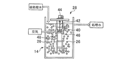
- the air diffuser is not a diffuser as conventionally used, but an air diffuser having a function of dissolving oxygen in the water to be treated and a stirring function of flowing the water to be treated together with the carrier 26 in the water to be treated.
- the draft tube aerator 28 is suitable.
- FIG. 2 shows one of the reaction vessels 14 divided into three by the partition wall 30 in FIG.
- the draft tube aerator 28 is known.
- the draft tube aerator 28 has a shaft 42 provided with an impeller 40 at the lower end, and a drive device 44 coupled to the shaft 42.
- a diffuser pipe 46 positioned immediately below the impeller 40, a blower 32 communicating with the diffuser pipe 46, and a diameter substantially the same as the diameter of the impeller 40, and extends downward from the impeller 40.
- the water to be treated and air bubbles are guided to the bottom of the tank to increase the stirring power at the bottom and increase the efficiency of dissolving oxygen.
- the blower 32 is connected to the DO meter 20 and adjusts the amount of air (aeration amount) sent from the blower 32 according to the DO value in the treated water measured by the DO meter 20, and thus the DO value in the treated water. Is set to an appropriate value.
- FIG. 13 shows that the removal rate of dissolved nitrogen, the NO 2 -N production concentration, and the NO 3 -N production concentration in the treated water denitrified by the biological nitrogen removal method of the present invention are different from each other in the DO against the soluble nitrogen load. It is a graph which shows how it changes with ratios. As shown in this graph, if the ratio of DO to soluble nitrogen load is too low, a sufficient oxygen concentration is secured in the outer layer of the two layers of microbial membranes that predominately nitrite-type nitrifying bacteria. Therefore, the amount of nitrous acid produced by the nitrite type nitrification reaction becomes insufficient, and only a low nitrogen removal rate can be obtained.
- nitrous acid produced by nitrite-type nitrification reaction is further oxidized by nitric acid-type nitrification reaction due to excess oxygen, and nitric acid is produced.
- the oxygen reaches the inner layer that predominates with anaerobic ammonia-oxidizing bacteria and cannot sufficiently satisfy the anaerobic conditions, so the anaerobic ammonia oxidation reaction is not promoted and is low Only nitrogen removal rate is obtained.
- FIG. 14 shows that the removal rate of soluble nitrogen, the NO 2 -N production concentration, and the NO 3 -N production concentration in the treated water denitrified by the biological nitrogen removal method of the present invention with respect to the soluble total organic carbon load It is a graph which shows how it changes with the ratio of DO. As shown in this graph, when the ratio of DO to the soluble total organic carbon load is low, it becomes difficult to secure the amount of DO necessary for nitrogen removal reaction due to the consumption of DO by organic matter, and only a low nitrogen removal rate is obtained. Absent.
- an NH 4 -N meter 50 for measuring ammonia nitrogen (NH 4 -N) concentration and a NO 2 -N meter 52 for measuring nitrite nitrogen (NO 2 -N) concentration are provided downstream of the reaction tank 14.
- the NO 3 -N meter 54 for measuring nitrate nitrogen (NO 3 -N) concentration is provided, and the NH 4 -N concentration, the NO 2 -N concentration, and the NO 3 -N concentration of the water to be treated flowing out from the reaction tank 14 are provided.
- the concentration is measured, and the amount of aeration (the amount of air supplied to the air diffuser 56) is adjusted as shown in (a) to (c) below.
- the amount of aeration (the amount of air supplied to the air diffuser 56) is adjusted as shown in (a) to (c) below.
- C Increase the amount of aeration when the NH 4 -N concentration exceeds a certain set value.
- (A) and (b) suppress excessive aeration, and (c) suppresses aeration shortage.
- the priority of adjustment is in the order of (a), (b), and (c).
- a mixing tank 16 is connected to the downstream side of the reaction tank 14 via a pipe with a PO 4 meter 22 attached in the middle, and a motor-driven stirring device is provided in the mixing tank 16. is set up.
- the PO 4 concentration of the treated water treated with the nitrite type nitrifying bacteria and the anaerobic ammonia oxidizing bacteria in the reaction tank 14 is measured by the PO 4 meter, and the solid organic matter and the PO 4 concentration are measured according to the PO 4 concentration.
- a flocculant for agglomerating phosphorus such as polyaluminum chloride (PAC)
- PAC polyaluminum chloride
- a second settling tank 18 is provided downstream of the mixing tank 16 via a pipe, and solid organic substances and / or phosphorus aggregated by the coagulant in the mixing tank 16 is precipitated in the second settling tank 18. I am doing so.
- the precipitated phosphorus is periodically withdrawn from the bottom of the second settling tank 18 and sent to a sludge treatment facility for disposal.
- the supernatant liquid in the second sedimentation tank 18 is sent out of the system as treated water after denitrification and phosphorus removal.
- the PO 4 meter 22, the flocculant injection pump 24, and the mixing tank 16 may be installed on the upstream side of the first settling tank 12.
- a flocculant is added to the water to be treated before being biologically nitrogen-removed in the reaction tank 14, and the flocculant is agglomerated in the first settling tank 12 installed on the upstream side of the reaction tank 14.
- water to be treated is supplied to the first settling tank 12.
- the foreign material in to-be-processed water precipitates
- the supernatant liquid in the 1st sedimentation tank 12 is sent to the reaction tank 14 through piping.
- the sludge which settled on the bottom in the 1st sedimentation tank 12 is suitably extracted, sent to a sludge treatment facility, and is disposed.
- the water to be treated is removed in the reaction tank 14 by the biological nitrogen removal method of the present invention. More specifically, the water to be treated that has flowed into the reaction tank 14 is agitated by a draft tube aerator 28, and a plurality of carriers in which nitrite-type nitrifying bacteria and anaerobic ammonia oxidation-reacting bacteria are supported on the surface portion. As shown by the arrows in FIG. 2, the air 26 uniformly flows in the water to be treated, and air is sent into the water to be treated by the draft tube aerator 28.
- the concentration of dissolved oxygen in the water to be treated is measured by the DO meter 20, thereby controlling the blower 32 of the draft tube aerator 28 so that a predetermined aerobic condition is created in the water to be treated. Further, based on the soluble nitrogen concentration of the water to be treated that has flowed into the reaction tank 14, the carrier loading rate of the carrier 26 to be poured into the water to be treated is adjusted in advance.
- the carrier charging rate is defined as the surface area of the carrier 26 per unit volume of the reaction tank 14, and by increasing or decreasing the number of carriers 26 charged into the reaction tank 14, such a carrier charging rate. Can be adjusted.
- the water to be treated which has flowed into the reaction vessel 14 is favorably produced by the nitrite-type nitrifying bacteria which are dominant species in the outer layer of the microbial film supported on the surface of each carrier 26. Under tempering conditions, a nitrite-type nitrification reaction occurs and ammonia nitrogen is converted to nitrite nitrogen.
- each carrier 26 has strength characteristics that can withstand the shearing force acting on the surface portion of each carrier 26 due to the strong stirring force by the air diffuser, and each carrier 26 is in the water to be treated.
- the stirring force of the water to be treated by the draft tube aerator 28 is increased based on the knowledge that the moving speed of ammonia ions per membrane surface to the microorganism membrane can be increased.
- the flow rate of the water to be treated with respect to the surface portion of the carrier 26 on which the bacteria are supported on the surface portion is increased, thereby increasing the rate of movement of ammonia ions per unit surface area of the membrane to the microbial membrane.
- the amount of nitrous acid produced by the nitric acid type nitrification reaction may be at a level that inhibits the nitric acid type nitrification reaction.
- the nitrogen removal efficiency may be further increased by adjusting the flow rate of the water to be treated relative to the surface of the carrier through the adjustment of the stirring rate of the water to be treated by the draft tube aerator 28 together with the adjustment of the carrier charging rate. .
- the generation of nitrous acid occurs at a level that inhibits the nitric acid-type nitrification reaction, so that nitrous acid is generated, but the generated nitrous acid is not converted into nitric acid, and an anaerobic ammonia oxidation reaction It is possible to secure the nitrite nitrogen necessary for the production.
- the amount of nitrous acid produced by the nitrite-type nitrification reaction can be reduced by adjusting the carrier charging rate in the water to be treated and / or the flow rate of the water to be treated relative to the surface of the carrier, so As a result, the ammonia nitrogen and nitrite nitrogen necessary for the anaerobic ammonia oxidation reaction are secured.
- anaerobic ammonia oxidation is performed under pseudo-anaerobic conditions by anaerobic ammonia-oxidizing bacteria that are dominant species in the inner layer of the two-layer microbial membranes supported on the surface of each carrier 26. Reaction occurs and ammonia nitrogen and nitrite nitrogen are converted to nitrogen.
- the water to be treated is sent to the mixing tank 16 through a pipe.
- the flocculant injection pump 24 based on the PO 4 concentration measured by the PO 4 meter
- the amount of the flocculant supplied into the mixing tank 16 is adjusted, and the water to be treated is stirred.
- PO 4 is aggregated by the flocculant.
- the water to be treated is sent to the second settling tank 18 through a pipe, where the aggregated solid organic matter and / or phosphorus is precipitated, and the precipitated sludge is sent to a sludge treatment facility for disposal.
- the supernatant liquid that has been subjected to biological nitrogen removal and phosphorus removal treatment in the second sedimentation tank 18 is reused or disposed of separately as treated water.
- the main water treatment may be performed by continuously injecting water to be treated, or in some cases by batch treatment.
- the water treatment system 10 having the above configuration, it is possible to reduce the amount of oxygen necessary to denitrify the water to be treated by performing denitrification using an anaerobic ammonia oxidation reaction.
- a carrier carrying bacteria is used instead of activated sludge for denitrification, a facility for returning activated sludge to the reaction tank is unnecessary, and at the same time, solids that are inevitably mixed in activated sludge. It is possible to significantly reduce the amount of oxygen necessary for water treatment of water to be treated containing soluble nitrogen such as ammonia nitrogen, without oxygen being consumed when the organic substances are decomposed. .
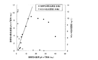
- FIG. 17 is a graph showing how the dissolved nitrogen removal rate and NO 3 —N production concentration change with the influent dissolved nitrogen load. As shown in this graph, when the inflow soluble nitrogen load is in the range of 4.0 to 11.5 g / m 2 carrier / day, the soluble nitrogen removal rate increases almost linearly, and the soluble nitrogen removal rate (graph The slope of the straight line) is the maximum.
- the inflow soluble nitrogen load is less than 4.0 g / m 2 carrier / day, the NO 3 —N production concentration is high, and therefore it is considered difficult to suppress the nitric acid-type nitrification reaction, and the 11.5 g / m 2 carrier Beyond / day, the soluble nitrogen removal rate begins to decline.
- the specific carrier loading rate is preferably adjusted to 4 to 40 m 2 / m 3 , and if adjusted within such a range, the amount of nitrous acid produced by the nitrite-type nitrification reaction is reduced to the nitrate-type nitrification reaction. Can be raised to such a level that it can be suppressed, and a high removal rate of soluble nitrogen can be obtained.
- stirring a to-be-processed water so that the maximum flow rate of the to-be-processed water in a reaction tank may be 0.7 m / sec or more. As a result of such stirring, the flow rate of the water to be treated with respect to the surface of the carrier increases. As a result, the amount of nitrous acid produced by the nitrite-type nitrification reaction can be increased to a level that inhibits the nitrate-type nitrification reaction, and high dissolution Nitrogen removal rate is obtained.
- the biological nitrogen removal method of the present invention is preferably performed in a state where the ORP (oxidation-reduction potential) of the water to be treated is ⁇ 150 mV or less, and more preferably in a state where it is ⁇ 300 mV or less.
- FIG. 18 is a graph showing how the soluble nitrogen removal rate changes depending on the redox potential of the inflow water in the reaction vessel. As shown in this graph, when the oxidation-reduction potential of the influent water in the reaction vessel is ⁇ 150 mV or less, particularly ⁇ 300 mV or less, a high removal rate of soluble nitrogen can be obtained. The rate drops.
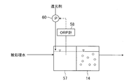
- a method for reducing the ORP includes a method of injecting a reducing agent into the water to be treated.
- an ORP adjustment tank 57 is provided in the upstream (upstream side) of the reaction tank 14, and the ORP water to be treated flowing into the ORP adjustment tank 57 is measured with an ORP meter 58.
- the amount of the reducing agent injected into the ORP adjustment tank 57 is adjusted by controlling the reducing agent injection pump 60 so as to have a predetermined value.
- the water to be treated whose ORP is adjusted to a predetermined value by the injection of the reducing agent flows into the reaction tank 14 at the subsequent stage (downstream side).
- sludge generated in a water treatment process such as drawn sludge in the first settling tank may be used, or industrially produced chemicals may be used.
- chemical it is preferable to use a chemical that is not easily oxidized by the organic matter contained in the water to be treated.
- sodium sulfide can be suitably used.
- Nitrogen removal can be carried out by the biological nitrogen removal method of the present invention, and soluble organic matter and phosphorus can be removed by using activated sludge. Nitrogen removal by the nitrogen removal method is preferably carried out without allowing activated sludge to flow into the reaction tank. If activated sludge flows into the reaction tank, the reaction by the bacteria in the biological nitrogen removal method of the present invention may be inhibited.
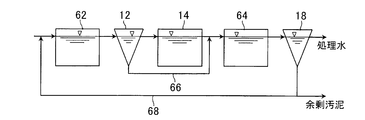
- FIG. 19 is a flow diagram in the case where nitrogen removal is performed by the biological nitrogen removal method of the present invention, and soluble organic matter and phosphorus are removed using activated sludge.
- the anaerobic tank 62 is installed between the first precipitation tank 12 and the reaction tank 14
- the aerobic tank 64 is installed between the reaction tank 14 and the second precipitation tank 18, and the first precipitation tank
- the activated sludge does not flow into the reaction tank 14.
- the soluble organic matter and phosphorus can be removed using activated sludge.
- the anaerobic tank 62 soluble organic substances in the water to be treated are removed by activated sludge. Thereafter, the water to be treated in the anaerobic tank 62 flows into the first settling tank 12 along with the activated sludge, and the activated sludge and the solid organic matter settle and separate in the first settling tank 12. And the supernatant liquid which does not contain activated sludge and solid organic matter flows into the reaction tank 14, and after nitrogen is removed by the biological nitrogen removal method of the present invention in the reaction tank 14, it enters the aerobic tank 64. Inflow.
- the activated sludge settled and separated in the first settling tank 12 flows into the aerobic tank 64 through the bypass 66 without flowing into the reaction tank 14.
- the activated sludge that has flowed into the aerobic tank 64 in this way ingests and accumulates phosphorus contained in the nitrogen-treated water that has also flowed into the aerobic tank 64.
- the water to be treated from which phosphorus has been removed by ingesting phosphorus into the activated sludge moves to the second settling tank 18 together with the activated sludge that has accumulated phosphorus, and the activated sludge and other water in the second settling tank 18 Solids settle and separate.
- the activated sludge and the supernatant liquid that does not contain solids are sent out of the system, while the activated sludge separated and separated is a part of Is discharged to the outside of the system as excess sludge, and the remainder is returned to the anaerobic tank 62 through the return path 68 while accumulating phosphorus.
- the activated sludge thus returned to the anaerobic tank 62 releases phosphorus accumulated in the anaerobic tank 62 and removes soluble organic substances in the water to be treated again.
- a flocculant may be added to the activated sludge so as to aggregate phosphorus.
- the nitrogen removal of the water to be treated flows into the reaction tank 14 by the biological nitrogen removal method of the present invention. It can be said that the removal of soluble organic matter and phosphorus is performed using activated sludge.
- the anaerobic tank 62 exists on the upstream side of the reaction tank 14 as described above, the anaerobic tank 62 functions to lower the ORP of the water to be treated, and thus, without adding a reducing agent as described above, ORP of to-be-processed water can be reduced to a suitable range, and a running cost falls compared with the case where a reducing agent is added.
- the carrier charging rate is adjusted by adjusting the number of carriers charged into the reaction tank.
- the present invention is not limited to this.
- the surface shape of the carrier is changed.
- the carrier loading rate may be adjusted by changing the surface area of the carrier.
- the inside of a single reaction vessel is partitioned by a partition.
- the present invention is not limited thereto.
- the inside of the reaction vessel may be a single space without partitioning by a partition. Good.
- the carrier has water-absorbing characteristics and / or hydrophilic characteristics capable of supporting the microbial membrane, and the carrier is treated water.
- Other types of resins may be used as long as they have strength characteristics that can withstand the shearing force acting on the carrier by flowing in the substrate.
- Example 1 The present inventor conducted a test at a practical level for normal sewage using the reaction tank 14 described in the above embodiment, and diffused sewage as water to be treated with a draft tube aerator.
- the carrier carrying the surface nitrifying bacteria and anaerobic ammonia-oxidizing bacteria on the surface is stirred so as to flow in the sewage, the ammonia nitrogen concentration in the water to be treated is adjusted by adjusting the carrier input rate.
- the denitrification efficiency at a practical level could be ensured while relaxing restrictions on water temperature, DO value, and pH value.
- the denitrification efficiency is the amount of nitrogen removed per unit time and per unit reaction volume.
- Table 1 shows the current operating condition (the operating condition in the embodiment of the present invention) in comparison with the operating condition disclosed in Patent Document 2.
- Table 2 shows the specifications of the carrier 26 employed this time.
- the reaction tank 14 the nitrite type nitrifying bacteria contributing to the nitrite type nitrification reaction are predominated as the dominant species, and the anaerobic ammonia oxidizing bacteria contributing to the anaerobic ammonia oxidation reaction are dominant.
- a carrier 26 having two layers of microbial membranes supported on the inside is used on the inside, and the outer layer of the microbial membrane is used as a dominant species.
- the existing nitrifying nitrifier causes a nitrifying nitrification reaction under aerobic conditions, which converts part of the ammonia nitrogen to nitrite nitrogen and then into the inner layer of the microbial membrane Anaerobic ammonia oxidizing bacteria present as dominant species convert ammonia nitrogen and nitrite nitrogen to nitrogen under anaerobic conditions.
- the carrier is caused to flow by the stirring means, whereas under the operating conditions disclosed in Patent Document 2, the carrier is fixed.
- the conditions of the water to be treated are a water temperature of 15 to 29 ° C., an inflow ammoniacal nitrogen concentration of 10 to 15 mg / L, and a DO value of 2.5 to 3.
- the water to be treated has a water temperature of 20 ° C. or higher, an inflow ammoniacal nitrogen concentration of 200 mg / L or higher, and a DO value of 0.5 mgO. 2 / L or less, and comparing the two, the current operating condition is for water to be treated having a normal temperature and a low ammoniacal nitrogen concentration, and the restriction on the DO value is relaxed.
- the carrier 26 is a granular resin carrier and contains 84.5% of a hydrophilic resin and 6.5% of a crosslinking agent.
- the one made of resin was adopted.
- a strength characteristic capable of withstanding a shearing force acting on the surface portion of the carrier 26 due to the stirring force by the draft tube aerator 28 is provided.
- aeration is performed using a diffuser, and the stirring force for the water to be treated is set smaller than that in the current operation conditions.
- the carrier input rate is 15 m 2 total surface area of the carrier / m 3 tank volume, and thereby the inflowing ammonia nitrogen load is 6.0 to 9.0 g / m 2. Maintained at carrier / day.
- the inflow ammoniacal nitrogen load is 1 to 8 g / m 2 carrier / day.
- the carrier loading rate is set to a low level, the thickness of the microbial film of each carrier 26 is increased, and the carrier 26 is caused to flow in the water to be treated by the draft tube aerator 28.
- the removal rate of ammonia nitrogen per unit surface area of the carrier increases, and the nitrite type nitrification reaction is promoted to the extent that the nitrate type nitrification reaction is suppressed.
- the reaction rate of the nitrite type nitrification bacteria is increased from that of the nitrate type nitrification bacteria.
- the reaction rate of the nitrite type nitrification bacteria is increased from that of the nitrate type nitrification bacteria, and the nitrite type nitrification reaction is performed. It is presumed that it was promoted (see FIG. 9).
- Example 2 In order to confirm the influence of the carrier charging rate on the nitrogen removal rate, the present inventor took out a small amount of the carrier used for continuous operation in Example 1 and covered it with the sewage in the actual sewage treatment plant. It was put into a beaker accommodated as treated water, and the following experiment (batch test) was performed. The experimental conditions are as follows.
- Bacteria Nitrite-type nitrifying bacteria and anaerobic ammonia-oxidizing bacteria
- Bacterial support method Using a cylindrical ( ⁇ 4.0mm ⁇ L4.3mm) polyurethane resin carrier, nitrite-type nitrifying bacteria predominate Supports anaerobic ammonia-oxidizing bacteria on the outside as a dominant species and carries two layers of microbial membranes on the inside in a form surrounded by the nitrite-type nitrifying bacteria.
- Treated water Aeration of sewage treatment plant Precipitate supernatant of tank mixture (4) Amount of water: 300 mL (beaker) (5) DO supply method: aeration and stirring
- Example 1 In Example 1, the carrier input rate is 15 m 2 The total surface area of the carrier / m 3 The volume of the used carrier is taken out, and the carrier input rate is 90 m 2 with respect to 300 mL of water to be treated. The surface area / m 3 tank volume was added and stirred sufficiently (FIG. 5).
- the carrier loading rate is 15 m 2 The total surface area of the carrier / m 3 The volume of the used carrier is taken out, and the carrier loading rate is 30 m 2 with respect to the amount of water to be treated of 300 mL. The surface area / m 3 of the tank volume was added and stirred sufficiently (FIG. 6).
- [NO X -N] is the sum of [NO 3 -N] (nitrate nitrogen concentration) and [NO 2 -N] (nitrite nitrogen concentration), and ionic nitrogen is The sum of [NH 4 -N] (ammonia nitrogen concentration) and [NO X -N], the NH 4 -N decrease rate (mgN / L / hr) is ([NH 4 -N] (at 0 hours) + [NH 4 -N] (after 4 hours) / 4, NH 4 -N decrease rate (mgN / m 2 support surface area / hr) is NH 4 -N decrease rate / support surface area, ionic nitrogen decrease rate (MgN / L / hr) is (ionic nitrogen (at 0 hours) + ionic nitrogen (after 4 hours)) / 4, ionic nitrogen reduction rate (mgN / m 2 carrier surface area / hr) is ion
- the lower the carrier input rate, the lower the ionic nitrogen reduction rate (mgN / L / hr) or (mgN / m 2 carrier surface area / hr) and the NH 4 -N reduction rate (mgN / L / hr) or (mgN / m 2 support surface area / hr) increases, while the NO x -N increase rate (mgN / L / hr) or (mgN / m 2 support surface area / hr) decreases I understand.
- the NH 4 —N reduction rate can be regarded as a nitrification rate
- the ionic nitrogen reduction rate can be regarded as an anaerobic ammonia oxidation rate.
- the present inventors have confirmed that the carrier loading rate can affect the promotion of the nitrite type nitrification reaction, the inhibition of the nitrate type nitrification reaction, and the promotion of the anaerobic ammonia oxidation reaction.
- the present invention using the fact that the production of nitrous acid contributes to the inhibition of the nitric acid type nitrification reaction, in order to simultaneously achieve the promotion of the nitrite type nitrification reaction and the suppression of the nitric acid type nitrification reaction,
- the restrictions on the ammonia nitrogen concentration of the water to be treated, the water temperature in the reaction tank, the DO value, and the pH value are relaxed
Abstract
Priority Applications (7)
| Application Number | Priority Date | Filing Date | Title |
|---|---|---|---|
| KR1020117016594A KR101473050B1 (ko) | 2008-12-28 | 2009-12-18 | 생물학적 질소 제거 방법, 장치 및 이를 위한 담체 |
| JP2010544045A JP5764330B2 (ja) | 2008-12-28 | 2009-12-18 | 生物学的窒素除去方法 |
| CN2009801528623A CN102264651B (zh) | 2008-12-28 | 2009-12-18 | 生物学脱氮方法、装置、以及所用的载体 |
| EP09834809.7A EP2377819B1 (fr) | 2008-12-28 | 2009-12-18 | Procédé permettant d'éliminer l'azote biologique |
| CA 2748534 CA2748534C (fr) | 2008-12-28 | 2009-12-18 | Procede et dispositif permettant d'eliminer l'azote biologique et son support |
| US13/167,327 US8246830B2 (en) | 2008-12-28 | 2011-06-23 | Method and device for removing biological nitrogen and support therefor |
| HK12101789A HK1162165A1 (en) | 2008-12-28 | 2012-02-23 | Method and device for removing biological nitrogen and support therefor |
Applications Claiming Priority (2)
| Application Number | Priority Date | Filing Date | Title |
|---|---|---|---|
| JP2008335593 | 2008-12-28 | ||
| JP2008-335593 | 2008-12-28 |
Related Child Applications (1)
| Application Number | Title | Priority Date | Filing Date |
|---|---|---|---|
| US13/167,327 Continuation US8246830B2 (en) | 2008-12-28 | 2011-06-23 | Method and device for removing biological nitrogen and support therefor |
Publications (1)
| Publication Number | Publication Date |
|---|---|
| WO2010074008A1 true WO2010074008A1 (fr) | 2010-07-01 |
Family
ID=42287618
Family Applications (1)
| Application Number | Title | Priority Date | Filing Date |
|---|---|---|---|
| PCT/JP2009/071181 WO2010074008A1 (fr) | 2008-12-28 | 2009-12-18 | Procédé et dispositif permettant d'éliminer l'azote biologique et son support |
Country Status (8)
| Country | Link |
|---|---|
| US (1) | US8246830B2 (fr) |
| EP (1) | EP2377819B1 (fr) |
| JP (2) | JP5764330B2 (fr) |
| KR (1) | KR101473050B1 (fr) |
| CN (1) | CN102264651B (fr) |
| CA (1) | CA2748534C (fr) |
| HK (1) | HK1162165A1 (fr) |
| WO (1) | WO2010074008A1 (fr) |
Cited By (8)
| Publication number | Priority date | Publication date | Assignee | Title |
|---|---|---|---|---|
| JP2011104585A (ja) * | 2009-10-20 | 2011-06-02 | Metawater Co Ltd | 排水処理方法及び排水処理装置 |
| WO2012052443A1 (fr) * | 2010-10-18 | 2012-04-26 | Veolia Water Solutions & Technologies Support | Procede de traitement d'eau au sein d'un reacteur biologique sequentiel comprenant une mesure en ligne de la concentration en nitrites |
| WO2012085288A1 (fr) * | 2010-12-24 | 2012-06-28 | Veolia Water Solutions & Technologies Support | Procede et installation de traitement d ' eau par nitritation - denitritation comprenant au moins une etape aeree et une etape de controle de l'apport en oxygene au cours de l'etape aeree |
| JPWO2011148949A1 (ja) * | 2010-05-25 | 2013-07-25 | メタウォーター株式会社 | 嫌気性アンモニア酸化反応を利用した生物学的窒素除去方法 |
| JP2013230413A (ja) * | 2012-04-27 | 2013-11-14 | Japan Organo Co Ltd | 窒素含有排水の処理方法および窒素含有排水の処理装置 |
| JP2017144402A (ja) * | 2016-02-18 | 2017-08-24 | 水ing株式会社 | アンモニア性窒素含有被処理液の硝化脱窒処理方法及び装置 |
| CN109354165A (zh) * | 2018-12-03 | 2019-02-19 | 巩义市宏盛稀有金属有限公司 | 一种采用复合式mbr一体化处理生活污水的方法 |
| WO2019225113A1 (fr) * | 2018-05-21 | 2019-11-28 | 株式会社日立製作所 | Procédé de traitement à l'azote |
Families Citing this family (25)
| Publication number | Priority date | Publication date | Assignee | Title |
|---|---|---|---|---|
| JP5126690B2 (ja) * | 2009-03-25 | 2013-01-23 | 株式会社日立プラントテクノロジー | 廃水処理方法 |
| EP2421544B1 (fr) | 2009-04-22 | 2015-06-03 | Ofir Menashe | Micro-organisme comprenant des particules et ses utilisations |
| WO2012160526A2 (fr) * | 2011-05-23 | 2012-11-29 | Ofir Menashe | Formulations à base de particules contenant des micro-organismes et leurs utilisations |
| WO2014043547A1 (fr) | 2012-09-13 | 2014-03-20 | D.C. Water & Sewer & Authority | Procédé et appareil pour l'élimination d'azote dans un traitement d'eaux usées |
| CN102826656B (zh) * | 2012-09-19 | 2013-09-25 | 上海水合环境工程有限公司 | 一种工业污水深度脱氮及回用工艺 |
| US9751788B2 (en) | 2014-05-02 | 2017-09-05 | Baker Hughes Incorporated | Bacterial additives for biological and/or chemical contaminants within water-based fluids |
| EP3197838B1 (fr) * | 2014-09-24 | 2020-01-08 | Veolia Water Solutions & Technologies Support | Procédé anammox dans une station d'épuration d'eaux usées |
| JP6448382B2 (ja) * | 2015-01-19 | 2019-01-09 | 水ing株式会社 | 窒素含有廃水の脱窒方法及び脱窒装置 |
| CN104926016B (zh) * | 2015-05-13 | 2017-01-25 | 合肥徽锐工程科技有限公司 | 一种高盐环氧废水处理方法 |
| WO2017052167A1 (fr) | 2015-09-23 | 2017-03-30 | 주식회사 부강테크 | Appareil de traitement d'eaux usées utilisant un procédé de biofiltration pour le prétraitement d'un procédé d'élimination d'azote raccourci |
| DE102016113796A1 (de) * | 2016-07-27 | 2018-02-01 | Wte Wassertechnik Gmbh | Verfahren und Anlage zur weitergehenden mikrobiologischen Reinigung von stickstoffhaltigen Abwässern |
| JP6872921B2 (ja) * | 2017-02-09 | 2021-05-19 | 学校法人 東洋大学 | 窒素含有廃水の処理装置及び処理方法 |
| CN107487847B (zh) * | 2017-08-31 | 2020-11-27 | 北京工业大学 | 一种一体化厌氧氨氧化强化内源反硝化sbbr深度脱氮的方法 |
| KR102062431B1 (ko) * | 2017-12-20 | 2020-01-03 | 서울과학기술대학교 산학협력단 | 조류 - 아질산화 - 혐기성 암모늄 산화를 융합한 하수 내 질소 처리용 담체 |
| JP6601517B2 (ja) * | 2018-02-20 | 2019-11-06 | 栗田工業株式会社 | 好気性生物処理装置の運転方法 |
| JP6614253B2 (ja) * | 2018-02-20 | 2019-12-04 | 栗田工業株式会社 | 好気性生物処理装置及びその運転方法 |
| CN108373240B (zh) * | 2018-04-11 | 2021-07-27 | 东华大学 | 一种棉印染废水分质处理及回用集成化工艺 |
| CN112912347A (zh) | 2018-10-23 | 2021-06-04 | Bl 科技公司 | 负载aob和annamox细菌的mabr介质和废水全程自养脱氮的方法 |
| CN109336256B (zh) * | 2018-11-27 | 2023-09-26 | 河北大学 | 一种半短程硝化-厌氧氨氧化串联污水处理系统与方法 |
| CN110451641B (zh) * | 2019-08-29 | 2020-09-18 | 南京大学 | 一种短程反硝化与厌氧氨氧化耦合脱氮一体式系统的启动方法 |
| CN112694172B (zh) * | 2021-01-15 | 2024-01-23 | 青岛思普润水处理股份有限公司 | Canon与铁自养反硝化耦合同步脱氮除磷系统及运行方法 |
| CN113104966B (zh) * | 2021-03-05 | 2022-07-26 | 华南理工大学 | 一种尿素废水的高效自养脱氮处理方法 |
| CN114506926A (zh) * | 2022-02-15 | 2022-05-17 | 山东本源环境科技有限公司 | 一种厌氧氨氧化污水处理系统 |
| CN114671532B (zh) * | 2022-04-12 | 2023-07-21 | 青岛理工大学 | 一种水产养殖水处理用高活性硝化细菌生物膜的制备方法 |
| CN115161235A (zh) * | 2022-07-08 | 2022-10-11 | 山东美泉环保科技有限公司 | 一种厌氧氨氧化菌的培养方法及培养装置、及厌氧氨氧化菌在处理工业废水中的应用 |
Citations (9)
| Publication number | Priority date | Publication date | Assignee | Title |
|---|---|---|---|---|
| JP2001293494A (ja) * | 2000-04-11 | 2001-10-23 | Kurita Water Ind Ltd | 生物学的窒素除去方法 |
| JP2003154394A (ja) * | 2001-11-22 | 2003-05-27 | Ebara Corp | 生物学的窒素除去方法及び装置 |
| JP2004230259A (ja) * | 2003-01-29 | 2004-08-19 | Hitachi Plant Eng & Constr Co Ltd | 生物処理方法及び装置 |
| WO2005095289A1 (fr) * | 2004-03-30 | 2005-10-13 | Kumamoto Technology And Industry Foundation | Procédé de traitement des eaux usées contenant de l’ammoniaque |
| JP2006055739A (ja) * | 2004-08-19 | 2006-03-02 | Kurita Water Ind Ltd | 有機物及び窒素含有排水の処理方法 |
| WO2006035885A1 (fr) * | 2004-09-30 | 2006-04-06 | Kurita Water Industries Ltd. | Procédé de traitement de liquide contenant de l’azote et appareil ad hoc |
| JP2006088092A (ja) | 2004-09-27 | 2006-04-06 | Kurita Water Ind Ltd | 窒素含有液の処理方法および装置 |
| JP2008114191A (ja) * | 2006-11-07 | 2008-05-22 | Mitsui Eng & Shipbuild Co Ltd | アンモニア性窒素を含有する廃水の処理装置 |
| JP2008221160A (ja) * | 2007-03-14 | 2008-09-25 | Kobelco Eco-Solutions Co Ltd | 脱窒処理装置および脱窒処理方法 |
Family Cites Families (17)
| Publication number | Priority date | Publication date | Assignee | Title |
|---|---|---|---|---|
| JPS6238295A (ja) * | 1985-08-13 | 1987-02-19 | Ebara Res Co Ltd | 有機性汚水の処理方法 |
| DK112590D0 (da) * | 1990-05-07 | 1990-05-07 | S E Joergensen | Fremgangsmaade til fjernelse af nitrogen fra vandige oploesninger |
| JP3303665B2 (ja) * | 1996-05-17 | 2002-07-22 | 日立プラント建設株式会社 | 硝化・脱窒方法及び装置 |
| NL1005343C1 (nl) * | 1996-08-23 | 1998-02-26 | Univ Delft Tech | Werkwijze voor het behandelen van ammoniak-houdend afvalwater. |
| JP3608913B2 (ja) * | 1996-09-13 | 2005-01-12 | 日清紡績株式会社 | バイオリアクタ−用担体及び製造方法 |
| JP2000288568A (ja) * | 1999-04-06 | 2000-10-17 | Ataka Construction & Engineering Co Ltd | 汚水処理装置 |
| JP4514874B2 (ja) * | 2000-01-28 | 2010-07-28 | 日本エンバイロケミカルズ株式会社 | 水処理用担体、水処理用担体の製造方法および水処理用装置 |
| JP2001340075A (ja) * | 2000-05-31 | 2001-12-11 | Nisshinbo Ind Inc | バイオリアクター用担体、その製造方法及び該担体の使用方法 |
| JP4365512B2 (ja) * | 2000-06-12 | 2009-11-18 | 株式会社東芝 | 下水処理システムおよび計測システム |
| JP4613474B2 (ja) * | 2003-01-28 | 2011-01-19 | 栗田工業株式会社 | アンモニア含有水の処理方法 |
| JP2005161258A (ja) * | 2003-12-04 | 2005-06-23 | Japan Steel Works Ltd:The | 高濃度アンモニア含有ガスの亜硝酸化方法およびその装置 |
| JP4284700B2 (ja) * | 2004-03-25 | 2009-06-24 | 株式会社日立プラントテクノロジー | 窒素除去方法及び装置 |
| JP4678577B2 (ja) * | 2004-11-05 | 2011-04-27 | 株式会社日立プラントテクノロジー | 廃水処理システム |
| JP4600817B2 (ja) * | 2005-03-14 | 2010-12-22 | 株式会社日立プラントテクノロジー | アンモニア含有水の処理方法 |
| JP4734996B2 (ja) * | 2005-03-29 | 2011-07-27 | 栗田工業株式会社 | 窒素含有水の生物的処理方法および装置 |
| CA2550121A1 (fr) * | 2006-06-07 | 2007-12-07 | Flynn Water Technologies Inc. | Transporteur de biomasse facilitant la nitrification et la denitrification simultanees |
| JP5324269B2 (ja) * | 2009-03-13 | 2013-10-23 | 株式会社日立製作所 | 廃水処理方法及び廃水処理装置 |
-
2009
- 2009-12-18 CN CN2009801528623A patent/CN102264651B/zh active Active
- 2009-12-18 JP JP2010544045A patent/JP5764330B2/ja active Active
- 2009-12-18 EP EP09834809.7A patent/EP2377819B1/fr active Active
- 2009-12-18 WO PCT/JP2009/071181 patent/WO2010074008A1/fr active Application Filing
- 2009-12-18 KR KR1020117016594A patent/KR101473050B1/ko active IP Right Grant
- 2009-12-18 CA CA 2748534 patent/CA2748534C/fr active Active
-
2011
- 2011-06-23 US US13/167,327 patent/US8246830B2/en active Active
-
2012
- 2012-02-23 HK HK12101789A patent/HK1162165A1/xx unknown
-
2013
- 2013-11-15 JP JP2013237070A patent/JP5890374B2/ja active Active
Patent Citations (9)
| Publication number | Priority date | Publication date | Assignee | Title |
|---|---|---|---|---|
| JP2001293494A (ja) * | 2000-04-11 | 2001-10-23 | Kurita Water Ind Ltd | 生物学的窒素除去方法 |
| JP2003154394A (ja) * | 2001-11-22 | 2003-05-27 | Ebara Corp | 生物学的窒素除去方法及び装置 |
| JP2004230259A (ja) * | 2003-01-29 | 2004-08-19 | Hitachi Plant Eng & Constr Co Ltd | 生物処理方法及び装置 |
| WO2005095289A1 (fr) * | 2004-03-30 | 2005-10-13 | Kumamoto Technology And Industry Foundation | Procédé de traitement des eaux usées contenant de l’ammoniaque |
| JP2006055739A (ja) * | 2004-08-19 | 2006-03-02 | Kurita Water Ind Ltd | 有機物及び窒素含有排水の処理方法 |
| JP2006088092A (ja) | 2004-09-27 | 2006-04-06 | Kurita Water Ind Ltd | 窒素含有液の処理方法および装置 |
| WO2006035885A1 (fr) * | 2004-09-30 | 2006-04-06 | Kurita Water Industries Ltd. | Procédé de traitement de liquide contenant de l’azote et appareil ad hoc |
| JP2008114191A (ja) * | 2006-11-07 | 2008-05-22 | Mitsui Eng & Shipbuild Co Ltd | アンモニア性窒素を含有する廃水の処理装置 |
| JP2008221160A (ja) * | 2007-03-14 | 2008-09-25 | Kobelco Eco-Solutions Co Ltd | 脱窒処理装置および脱窒処理方法 |
Non-Patent Citations (2)
| Title |
|---|
| "Anaerobic ammonia oxidation for treatment of ammonium-rich wastewaters", JOUMAL OF ZHEJIANG UNIVERSITY SCIENCE B, 2008, pages 416 - 426 |
| See also references of EP2377819A4 |
Cited By (16)
| Publication number | Priority date | Publication date | Assignee | Title |
|---|---|---|---|---|
| JP2011104585A (ja) * | 2009-10-20 | 2011-06-02 | Metawater Co Ltd | 排水処理方法及び排水処理装置 |
| JPWO2011148949A1 (ja) * | 2010-05-25 | 2013-07-25 | メタウォーター株式会社 | 嫌気性アンモニア酸化反応を利用した生物学的窒素除去方法 |
| JP5932639B2 (ja) * | 2010-05-25 | 2016-06-08 | メタウォーター株式会社 | 嫌気性アンモニア酸化反応を利用した生物学的窒素除去方法 |
| CN103261103B (zh) * | 2010-10-18 | 2015-10-21 | 威立雅水务解决方案与技术支持公司 | 包括亚硝酸盐浓度在线测量的序列生物反应器内处理水的方法 |
| CN103261103A (zh) * | 2010-10-18 | 2013-08-21 | 威立雅水务解决方案与技术支持公司 | 包括亚硝酸盐浓度在线测量的序列生物反应器内处理水的方法 |
| WO2012052443A1 (fr) * | 2010-10-18 | 2012-04-26 | Veolia Water Solutions & Technologies Support | Procede de traitement d'eau au sein d'un reacteur biologique sequentiel comprenant une mesure en ligne de la concentration en nitrites |
| FR2969596A1 (fr) * | 2010-12-24 | 2012-06-29 | Veolia Water Solutions & Tech | Procede de traitement d'eau comprenant au moins une etape aeree et une etape de controle de l'apport en oxygene au cours de l'etape aeree |
| US8956540B2 (en) | 2010-12-24 | 2015-02-17 | Veolia Water Solutions & Technologies Support | Process and apparatus for controlling aeration during nitrification and denitrification of water |
| WO2012085288A1 (fr) * | 2010-12-24 | 2012-06-28 | Veolia Water Solutions & Technologies Support | Procede et installation de traitement d ' eau par nitritation - denitritation comprenant au moins une etape aeree et une etape de controle de l'apport en oxygene au cours de l'etape aeree |
| AU2011347092B2 (en) * | 2010-12-24 | 2016-11-17 | Veolia Water Solutions & Technologies Support | Method and facility for treating water by nitritation/denitritation comprising at least one aerated step and one step for controlling the oxygen input during the aerated step |
| JP2013230413A (ja) * | 2012-04-27 | 2013-11-14 | Japan Organo Co Ltd | 窒素含有排水の処理方法および窒素含有排水の処理装置 |
| JP2017144402A (ja) * | 2016-02-18 | 2017-08-24 | 水ing株式会社 | アンモニア性窒素含有被処理液の硝化脱窒処理方法及び装置 |
| WO2019225113A1 (fr) * | 2018-05-21 | 2019-11-28 | 株式会社日立製作所 | Procédé de traitement à l'azote |
| JP2019202244A (ja) * | 2018-05-21 | 2019-11-28 | 株式会社日立製作所 | 窒素処理方法 |
| JP7133359B2 (ja) | 2018-05-21 | 2022-09-08 | 株式会社日立製作所 | 窒素処理方法 |
| CN109354165A (zh) * | 2018-12-03 | 2019-02-19 | 巩义市宏盛稀有金属有限公司 | 一种采用复合式mbr一体化处理生活污水的方法 |
Also Published As
| Publication number | Publication date |
|---|---|
| US8246830B2 (en) | 2012-08-21 |
| KR20110111291A (ko) | 2011-10-10 |
| US20110253625A1 (en) | 2011-10-20 |
| JP2014036959A (ja) | 2014-02-27 |
| KR101473050B1 (ko) | 2014-12-15 |
| CN102264651B (zh) | 2013-12-11 |
| HK1162165A1 (en) | 2012-08-24 |
| CA2748534A1 (fr) | 2010-07-01 |
| CN102264651A (zh) | 2011-11-30 |
| EP2377819A1 (fr) | 2011-10-19 |
| EP2377819A4 (fr) | 2012-10-03 |
| EP2377819B1 (fr) | 2015-07-08 |
| JP5764330B2 (ja) | 2015-08-19 |
| JP5890374B2 (ja) | 2016-03-22 |
| CA2748534C (fr) | 2014-01-28 |
| JPWO2010074008A1 (ja) | 2012-06-14 |
Similar Documents
| Publication | Publication Date | Title |
|---|---|---|
| JP5890374B2 (ja) | 生物学的窒素除去装置及び水処理システム | |
| JP5932639B2 (ja) | 嫌気性アンモニア酸化反応を利用した生物学的窒素除去方法 | |
| KR101828212B1 (ko) | 하수처리장 수처리공정에서 혐기성 암모늄 산화 공법 기반의 하수처리 시스템 | |
| JP5961169B2 (ja) | 廃水からの最適化された栄養素の除去 | |
| CA2542894C (fr) | Methode de traitement d'eaux usees de divers milieux | |
| JP2005305410A (ja) | 窒素除去方法及び装置 | |
| JP6666165B2 (ja) | アンモニア性窒素含有被処理液の硝化脱窒処理方法及び装置 | |
| CN103068748A (zh) | 接触-稳定/初期-浮选混合 | |
| US8323487B2 (en) | Waste water treatment apparatus | |
| JP3925902B2 (ja) | 生物学的窒素除去方法及びその装置 | |
| KR20080019975A (ko) | 생물학적 활성조 및 전극시스템이 결합된 하이브리드형생물―전기화학적 생물막 연속회분식 반응기를 이용한오폐수 처리장치 | |
| JP4302341B2 (ja) | 生物学的窒素除去方法及び装置 | |
| KR102002230B1 (ko) | 혐기성 암모늄 산화 공법 기반의 하수처리장 수처리공정에서 질소 처리 효율 강화를 위한 하수처리 시스템 | |
| JP5581872B2 (ja) | アンモニア性窒素廃液の脱窒処理方法及び処理装置 | |
| JP6774341B2 (ja) | 窒素除去システムおよび窒素除去方法 | |
| KR101959145B1 (ko) | 혐기성 암모늄 산화 공법 기반 하수처리장 수처리공정에서 질소 및 인 처리 효율 강화를 위한 하수처리 시스템 | |
| JPH08141597A (ja) | 窒素及びフッ素含有排水の処理装置 | |
| JP2003071490A (ja) | 廃水からの窒素の除去方法 | |
| KR101959144B1 (ko) | 하수처리장 수처리공정에서 혐기성 암모늄 산화 공법 질소 및 인 동시 제거 하수처리 시스템 | |
| CN218910034U (zh) | 一种硝化短程反硝化厌氧氨氧化系统 | |
| KR100531516B1 (ko) | 하·폐수의 영양염류를 생물학적으로 처리하는 방법 | |
| CN115745170A (zh) | 一种硝化短程反硝化厌氧氨氧化系统及方法 | |
| JP2001286883A (ja) | 下水道終末処理場流入水の処理方法および処理装置 | |
| WO2005030654A1 (fr) | Procede et appareil pour la nitrification | |
| KR20110051307A (ko) | 연속 회분식 고도처리장치 및 이를 이용한 처리방법 |
Legal Events
| Date | Code | Title | Description |
|---|---|---|---|
| WWE | Wipo information: entry into national phase |
Ref document number: 200980152862.3 Country of ref document: CN |
|
| 121 | Ep: the epo has been informed by wipo that ep was designated in this application |
Ref document number: 09834809 Country of ref document: EP Kind code of ref document: A1 |
|
| ENP | Entry into the national phase |
Ref document number: 2010544045 Country of ref document: JP Kind code of ref document: A |
|
| NENP | Non-entry into the national phase |
Ref country code: DE |
|
| WWE | Wipo information: entry into national phase |
Ref document number: 2748534 Country of ref document: CA |
|
| WWE | Wipo information: entry into national phase |
Ref document number: 2009834809 Country of ref document: EP |
|
| ENP | Entry into the national phase |
Ref document number: 20117016594 Country of ref document: KR Kind code of ref document: A |