WO2010070712A1 - 3次元接触可能な転位歯形を有する波動歯車装置 - Google Patents
3次元接触可能な転位歯形を有する波動歯車装置 Download PDFInfo
- Publication number
- WO2010070712A1 WO2010070712A1 PCT/JP2008/003848 JP2008003848W WO2010070712A1 WO 2010070712 A1 WO2010070712 A1 WO 2010070712A1 JP 2008003848 W JP2008003848 W JP 2008003848W WO 2010070712 A1 WO2010070712 A1 WO 2010070712A1
- Authority
- WO
- WIPO (PCT)
- Prior art keywords
- section
- tooth
- deflection
- cross
- gear
- Prior art date
- Legal status (The legal status is an assumption and is not a legal conclusion. Google has not performed a legal analysis and makes no representation as to the accuracy of the status listed.)
- Ceased
Links
Images



Classifications
-
- F—MECHANICAL ENGINEERING; LIGHTING; HEATING; WEAPONS; BLASTING
- F16—ENGINEERING ELEMENTS AND UNITS; GENERAL MEASURES FOR PRODUCING AND MAINTAINING EFFECTIVE FUNCTIONING OF MACHINES OR INSTALLATIONS; THERMAL INSULATION IN GENERAL
- F16H—GEARING
- F16H55/00—Elements with teeth or friction surfaces for conveying motion; Worms, pulleys or sheaves for gearing mechanisms
- F16H55/02—Toothed members; Worms
- F16H55/08—Profiling
- F16H55/0833—Flexible toothed member, e.g. harmonic drive
-
- F—MECHANICAL ENGINEERING; LIGHTING; HEATING; WEAPONS; BLASTING
- F16—ENGINEERING ELEMENTS AND UNITS; GENERAL MEASURES FOR PRODUCING AND MAINTAINING EFFECTIVE FUNCTIONING OF MACHINES OR INSTALLATIONS; THERMAL INSULATION IN GENERAL
- F16H—GEARING
- F16H49/00—Other gearings
- F16H49/001—Wave gearings, e.g. harmonic drive transmissions
- F16H2049/003—Features of the flexsplines therefor
-
- Y—GENERAL TAGGING OF NEW TECHNOLOGICAL DEVELOPMENTS; GENERAL TAGGING OF CROSS-SECTIONAL TECHNOLOGIES SPANNING OVER SEVERAL SECTIONS OF THE IPC; TECHNICAL SUBJECTS COVERED BY FORMER USPC CROSS-REFERENCE ART COLLECTIONS [XRACs] AND DIGESTS
- Y10—TECHNICAL SUBJECTS COVERED BY FORMER USPC
- Y10T—TECHNICAL SUBJECTS COVERED BY FORMER US CLASSIFICATION
- Y10T74/00—Machine element or mechanism
- Y10T74/19—Gearing
Definitions
- the present invention relates to an improvement in the tooth profile of a rigid internal gear and a flexible external gear in a wave gear device. More specifically, both the gears maintain a wide range of engagement in the main cross section (axial cross section) set at a predetermined position in the tooth trace direction, and partially mesh in other axial perpendicular sections in the tooth trace direction. It is related with the shape of the tooth which can hold.
- the wave gear device is based on the founder C.I. W. Since the invention of Musser (Patent Document 1), various inventions of this apparatus have been made by many researchers including the present inventor to this day. There are various types of inventions related to the tooth profile.
- Patent Document 2 that the basic tooth profile is an involute tooth profile
- Patent Documents 3 and 4 a method of approximating the meshing of the teeth of the rigid internal gear and the flexible external gear with a rack.
- a wave gear device has an annular rigid internal gear, a flexible external gear arranged coaxially inside this, and a wave generator fitted inside this.
- the flexible external gear is formed on a flexible cylindrical body, a diaphragm extending in the radial direction from the rear end of the cylindrical body, and an outer peripheral surface portion on the front end opening side of the cylindrical body. With external teeth.
- the flexible external gear is bent in an elliptical shape by a wave generator, and meshes with the rigid internal gear at both ends of the major axis of the ellipse.
- the external teeth of the flexible external gear flexed in an elliptical shape increase in the amount of deflection substantially in proportion to the distance from the diaphragm from the diaphragm side toward the front end opening along the tooth trace direction. Yes. Further, as the wave generator rotates, each portion of the tooth portion of the flexible external gear repeatedly bends in the radial direction.
- An object of the present invention is to consider the coning of a flexible external gear and maintain a wide range of meshing in the main cross section (cross section perpendicular to the axis) in which both gears are set at predetermined positions in the tooth trace direction.
- An object of the present invention is to propose a wave gear device capable of maintaining partial meshing even in other cross-sectional directions perpendicular to the axis.
- a wave gear device of the present invention includes: An annular rigid internal gear, a flexible external gear coaxially disposed inside, and a wave generator fitted inside,
- the flexible external gear includes a flexible cylindrical body, a diaphragm extending in a radial direction from the rear end of the cylindrical body, and an outer peripheral surface portion on the opening side of the front end of the cylindrical body.
- the flexible external gear is bent in an elliptical shape by the wave generator, and meshes with the rigid internal gear at both ends of the major axis of the ellipse,
- the external teeth of the flexible external gear bent in an elliptical shape are substantially proportional to the distance from the diaphragm from the diaphragm side toward the front end opening side along the tooth trace direction.
- An axially perpendicular cross section at an arbitrary position in the tooth trace direction of the flexible external gear is defined as a main cross section, and the rigid internal gear and the flexible external gear in the main cross section are both spur gears of the module m,
- the number of teeth of the flexible external gear is set to be 2n less than the number of teeth of the rigid internal gear (n is a positive integer)
- a curve obtained by rotating the first similarity curve BC around the end point C of the first similarity curve BC by 180 degrees is multiplied by (1 ⁇ ) / ⁇ times with the end point C as the center of similarity.
- the distance in the tooth trace direction from the position of the main cross section of the external teeth to the front end of the external teeth on the front end opening side is a
- the distance in the tooth trace direction from the position of the main cross section of the external tooth to the rear end of the external tooth on the diaphragm side is b
- ⁇ ( ⁇ s + b + c) / (b + c)
- the tooth traces are shifted in consideration of the coning of the flexible external gear, and the relative movement trajectory of the teeth of the flexible external gear in the main section relative to the teeth of the rigid internal gear is By setting the movement trajectories of the other cross sections to share the bottom, rational meshing over the entire tooth trace is realized in addition to the regular wide meshing in the main cross section.
- FIG. 1 is a front view of a wave gear device that is the subject of the present invention
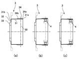
- FIGS. 2 (a) to 2 (c) show the situation in which the opening of the flexible external gear is bent in an elliptical shape in an axial section.
- 2A is a state before deformation
- FIG. 2B is a cross section including the major axis of the ellipse after deformation
- FIG. 2C includes the minor axis of the ellipse after deformation.
- Each section is shown. 2A to 2C, the solid line indicates the cup-shaped flexible external gear, and the broken line indicates the top hat-shaped flexible external gear.
- a wave gear device 1 includes an annular rigid internal gear 2, a flexible external gear 3 disposed on the inner side thereof, and a wave generator having an elliptical profile fitted on the inner side. 4.
- the difference in the number of teeth between the rigid internal gear 2 and the flexible external gear 3 is 2n (n is a positive integer), and the flexible external gear 3 of the wave gear device 1 is elliptical by a wave generator 4 having an elliptical profile. And is engaged with the rigid internal gear 2 at both ends of the elliptical long axis L1.
- the flexible external gear 3 includes a flexible cylindrical body 31, a diaphragm 32 that extends continuously in the radial direction from the rear end 31 b, a boss 33 that continues to the diaphragm 32, and the cylindrical body 31. External teeth 34 formed on the outer peripheral surface portion on the opening end 31a side.
- the cylindrical body 31 is directed from the diaphragm-side rear end 31b toward the opening end 31a.
- the amount of bending outward or inward in the radial direction is gradually increased.
- the outward deflection amount gradually increases in proportion to the distance from the rear end 31b to the opening end 31a, and is shown in FIG.
- the amount of inward bending gradually increases in proportion to the distance from the rear end 31b to the opening end 31a.
- the external teeth 34 formed on the outer peripheral surface portion on the opening end 31a side are also distanced from the rear end 31a from the external tooth rear end portion 34b in the tooth trace direction toward the external tooth front end portion 34a on the opening side.
- the amount of deflection gradually increases in proportion to.
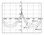
- FIG. 3 is a diagram showing a movement locus of the external teeth 34 of the flexible external gear 3 with respect to the rigid internal gear 2 obtained when the relative motion of both the gears 2 and 3 of the wave gear device 1 is approximated by a rack.
- the x axis indicates the translation direction of the rack
- the y axis indicates a direction perpendicular thereto.
- the y-axis origin in FIG. 3 is the average position of the amplitude of the movement trajectory.
- the deflection coefficient ⁇ The amount of deflection is set so that one unshifted movement trajectory can be obtained.
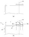
- the main cross section is set to a main cross section 30 at a position indicated by a straight line passing through the center of the ball of the bearing of the wave generator 4 as shown in FIG.
- ⁇ > 1 is a cross section extending from the main cross section 30 to the external tooth front end 34a
- ⁇ ⁇ 1 is a movement trajectory in a cross section extending from the main cross section 30 to the external tooth rear end 34b.
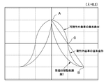
- FIG. 4 is an explanatory diagram showing the use range set in the tooth no-displacing movement locus M1 in the main cross section 30.
- the parameter ⁇ of the unshifted movement locus M1 of the main cross section 30 takes a range from ⁇ (point B: the bottom of the movement locus) to 0 (point A: the top of the movement locus), and the point B is similar.
- similarity transformation is performed by ⁇ times ( ⁇ ⁇ 1) to obtain a first similarity curve BC.
- This first similarity curve BC is adopted as a tooth profile curve that defines the basic tooth addendum of the rigid internal gear 2.
- the first similarity curve BC is rotated by 180 degrees, and the curve thus obtained is used as the center of similarity. Is multiplied by (1 ⁇ ) / ⁇ to obtain a second similarity curve AC.
- This two-similar curve AC is adopted as the basic tooth profile of the end of the flexible external gear 3.
- the basic tooth addendum of both gears is as follows.
- the meshing of the tooth profile of the main section 30 is the meshing of the tooth addendums of both gears 2 and 3, and when the flexible external gear 3 moves relative to the rigid internal gear 2 along the non-displacing movement locus M1.
- the tooth addendums contact each other continuously due to the nature of the similarity curve.
- the tooth profile at the root does not participate in meshing. Therefore, the tooth profile of each tooth base is not required to interfere with the tooth profile of the other tooth end, and can be set freely.
- FIG. 5 shows an example of the entire tooth profile of both gears 2 and 3. In this case, it is desirable to avoid the portion where the pressure angle of the tooth addendum is close to 0 degrees from the gear machining surface, and a straight tooth shape is formed from a point where the pressure angle is around 6 degrees, and the tooth shape is connected to the tooth root. . In the figure, the case where the pressure angle is 0 degree is shown for simplicity.
- the distance from the main cross section 30 to the external tooth front end 34a is a
- the distance from the main cross section 30 to the external tooth rear end 34b on the diaphragm side is b
- the external tooth rear end 34b to the diaphragm 32 is c.
- the amount of bending of the flexible external gear 3 is such that the linearity of the cylindrical generatrix is sufficiently maintained when the neutral cylindrical surface of the cylindrical body 31 is deformed into an ellipse by inserting the wave generator 4. For this reason, the amount of deflection is approximately proportional to the distance from the diaphragm by being applied to the opening from the diaphragm side on the long axis.
- the tooth profile has a deviation coefficient ⁇ > 1 due to the coning of the flexible external gear 3.
- the top portion of the positive displacement movement locus M2 is a positive displacement mesh that draws a loop. For this reason, it interferes with the tooth profile defined by the main cross section 30, and the meshing as in the main cross section 30 cannot be maintained as it is.
- the deviation coefficient is ⁇ ⁇ 1
- the negative excursion movement locus M3 interferes with the no-deviation movement locus M1, and in this case as well
- the meshing as in the main cross section 30 cannot be maintained.
- the outer teeth 34 are shifted as described below, and are hung from the main cross section 30 to the outer tooth front end portion 34a on the opening side and to the outer tooth rear end portion 34b on the diaphragm side.
- an attempt is made to guarantee a proper engagement, albeit partly, in part.
- the amount of displacement mnh is set so that the movement trajectories M2 and M3 in each cross section are in contact with the bottom of the no-deviation movement trajectory M1 in accordance with the deflection coefficient ⁇ of the bending.
- h ⁇ -1 (4) h is a positive or negative value, and is positive in each axis perpendicular section from the main cross section 30 to the outer tooth front end 34a on the opening side, and each axis perpendicular section from the main section 30 to the outer tooth rear end 34b on the diaphragm side. Then it becomes negative.
- FIG. 6B shows the tooth shape in this case.
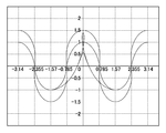
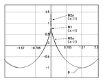
- FIG. 7 shows three types of movement trajectories M1, M2a, and M3a of the main cross section 30 of the external tooth 34 after the dislocation and the axially perpendicular cross section before and after the main cross section.
- These movement trajectories M2a and M3a are in contact with the non-deviation movement trajectory M1 of the main cross section 30 at the bottom (point P), and the trajectories are close to each other except for a part of the top.
- FIG. 8A to FIG. 8C show the appearance of the meshing of the tooth profile in the cross section perpendicular to each axis of the tooth profile of this example by rack approximation.
- FIG. 8A is an explanatory view showing a state of meshing in the cross section perpendicular to the axis of the external tooth front end portion 34a on the opening side
- FIG. 8B is an explanatory diagram showing a state of meshing in the main cross section 30
- FIG. 8C is an external view on the diaphragm side. It is explanatory drawing which shows the aspect of engagement in the tooth rear end part 34b.
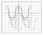
- the movement trajectories of the tooth profiles in the respective cross sections are in good agreement with the movement trajectory portions reaching their bottoms, indicating the possibility of meshing over the entire tooth trace of the tooth profile of this example.
Landscapes
- Engineering & Computer Science (AREA)
- General Engineering & Computer Science (AREA)
- Mechanical Engineering (AREA)
- Retarders (AREA)
Abstract
Description
円環状の剛性内歯車と、この内側に同軸状に配置された可撓性外歯車と、この内側に嵌めた波動発生器とを有し、
前記可撓性外歯車は、可撓性の円筒状胴部と、この円筒状胴部の後端から半径方向に延びているダイヤフラムと、前記円筒状胴部の前端開口側の外周面部分に形成した外歯とを備え、
前記可撓性外歯車は前記波動発生器によって楕円状に撓められ、楕円の長軸方向の両端部において前記剛性内歯車に噛み合っており、
楕円状に撓められた前記可撓性外歯車の前記外歯は、その歯筋方向に沿って、前記ダイヤフラムの側から前記前端開口側に向けて、前記ダイヤフラムからの距離にほぼ比例して撓み量が増加しており、
前記可撓性外歯車の歯筋方向における任意の位置の軸直角断面を主断面として定め、この主断面における前記剛性内歯車および前記可撓性外歯車を共にモジュールmの平歯車とし、
前記可撓性外歯車の歯数を前記剛性内歯車の歯数より2n枚(nは正の整数)少なく設定し、
前記主断面における前記可撓性外歯車の楕円状リム中立線における長軸位置において、その撓み前のリム中立円に対する撓み量2κmn(κは撓み係数)が、2mn(κ=1)の無偏位状態に撓むように設定し、
前記可撓性外歯車の歯形には、前記主断面を挟み、それらの歯筋方向の両側の歯形部分に転位を施してあり、
前記可撓性外歯車および前記剛性内歯車の噛み合いをラック噛み合いで近似し、前記可撓性外歯車の歯筋方向における前記主断面を含む各位置の軸直角断面において、前記波動発生器の回転に伴う前記可撓性外歯車の歯の前記剛性内歯車の歯に対する各移動軌跡を求め、
前記主断面において得られる無偏位移動軌跡における頂部の点Aから次の底部の点Bに至る曲線部分を、点Bを相似の中心としてλ倍(λ<1)に縮小した第1相似曲線BCを求め、当該第1相似曲線BCを前記剛性内歯車の歯末の基本歯形として採用し、
前記第1相似曲線BCの端点Cを中心として当該第1相似曲線BCを180度回転することにより得られた曲線を、当該端点Cを相似の中心として(1-λ)/λ倍した第2相似曲線を求め、当該第2相似曲線を前記可撓性外歯車の歯末の基本歯形とし、
前記主断面よりも前記ダイヤフラム側における負偏位状態(撓み係数κ<1)に撓む各軸直角断面において得られる各負偏位側移動軌跡、および、前記主断面よりも前記前端開口側における正偏位状態(撓み係数κ>1)に撓む各軸直角断面において得られる各正偏位側移動軌跡の双方が、前記主断面における前記無偏位移動軌跡の前記底部で接する曲線を描くように、前記可撓性外歯車の歯形における歯筋方向の転位の大きさが設定されていることを特徴としている。
当該外歯における前記主断面の位置から前記ダイヤフラム側の外歯後端までの歯筋方向の距離をb、
前記外歯後端から前記ダイヤフラムまでの距離をcとすると、
前記外歯における前記正偏位状態に撓む各軸直角断面の前記撓み係数κは、主断面30からの距離がsの位置において、次式で規定することができる。
κ=(s+b+c)/(b+c)
κ=(-s+b+c)/(b+c)
h=κ-1
図1は本発明の対象である波動歯車装置の正面図であり、図2(a)~(c)はその可撓性外歯車の開口部を楕円状に撓ませた状況を含軸断面で示す断面図であり、図2(a)は変形前の状態、図2(b)は変形後における楕円形の長軸を含む断面、図2(c)は変形後における楕円の短軸を含む断面をそれぞれ示してある。なお、図2(a)~(c)において実線はカップ状の可撓性外歯車を示し、破線はシルクハット状の可撓性外歯車を示す。
x=0.5mn(θ-κsinθ) (1)
y=κmncosθ
x=0.5(θ-κsinθ) (1A)
y=κcosθ
図4は主断面30における歯の無偏位移動軌跡M1に設定した利用範囲を示す説明図である。この図において、主断面30の無偏位移動軌跡M1のパラメーターθがπ(B点:移動軌跡の底部)から0(A点:移動軌跡の頂部)までの範囲を取り、B点を相似の中心として、この軌跡M1をλ倍(λ<1)に相似変換して第1相似曲線BCを得る。この第1相似曲線BCを剛性内歯車2の基本歯末歯形を規定する歯形曲線として採用する。
2相似曲線ACを可撓性外歯車3の歯末の基本歯形として採用する。
xCa=0.5{(1-λ)π+λ(θ-sinθ)}
yCa=λ(1+cosθ)-1 (0≦θ≦π) (2)
可撓性外歯車の歯末歯形の基本式:
xFa=0.5(1-λ)(π-θ+sinθ)
yFa=λ(1+cosθ)-cosθ (0≦θ≦π) (3)
図6を参照して、主断面30以外の軸直角断面の歯形の形成方法を説明する。まず、図6(a)に示すように、外歯の歯筋方向の全体の歯形を主断面30の歯形と同一の歯形とする。そして、当該歯形に対して、歯筋の位置に応じて以下のようにして設定した転位を施した転位歯形を求める。この転位歯形を主断面30以外の歯形として採用する。
κ=(s+b+c)/(b+c)
また、主断面30からダイヤフラム側の外歯後端34bに掛けての各軸直角断面の偏位係数は、主断面30からの距離をsとすると次のようになる。
κ=(-s+b+c)/(b+c)
h=κ-1 (4)
hは正負の値をとり、主断面30から開口側の外歯前端34aに掛けての各軸直角断面では正、主断面30からダイヤフラム側の外歯後端34bに掛けての各軸直角断面では負となる。図6(b)にはこの場合の歯の形状を示している。
Claims (2)
- 円環状の剛性内歯車と、この内側に同軸状に配置された可撓性外歯車と、この内側に嵌めた波動発生器とを有し、
前記可撓性外歯車は、可撓性の円筒状胴部と、この円筒状胴部の後端から半径方向に延びているダイヤフラムと、前記円筒状胴部の前端開口側の外周面部分に形成した外歯とを備え、
前記可撓性外歯車は前記波動発生器によって楕円状に撓められ、楕円の長軸方向の両端部において前記剛性内歯車に噛み合っており、
楕円状に撓められた前記可撓性外歯車の前記外歯は、その歯筋方向に沿って、前記ダイヤフラムの側から前記前端開口側に向けて、前記ダイヤフラムからの距離にほぼ比例して撓み量が増加しており、
前記可撓性外歯車の歯筋方向における任意の位置の軸直角断面を主断面として定め、この主断面における前記剛性内歯車および前記可撓性外歯車を共にモジュールmの平歯車とし、
前記可撓性外歯車の歯数を前記剛性内歯車の歯数より2n枚(nは正の整数)少なく設定し、
前記主断面における前記可撓性外歯車の楕円状リム中立線における長軸位置において、その撓み前のリム中立円に対する撓み量2κmn(κは撓み係数)が、2mn(κ=1)の無偏位状態に撓むように設定し、
前記可撓性外歯車の歯形には、前記主断面を挟み、それらの歯筋方向の両側の歯形部分に転位を施してあり、
前記可撓性外歯車および前記剛性内歯車の噛み合いをラック噛み合いで近似し、前記可撓性外歯車の歯筋方向における前記主断面を含む各位置の軸直角断面において、前記波動発生器の回転に伴う前記可撓性外歯車の歯の前記剛性内歯車の歯に対する各移動軌跡を求め、
前記主断面において得られる無偏位移動軌跡における頂部の点Aから次の底部の点Bに至る曲線部分を、点Bを相似の中心としてλ倍(λ<1)に縮小した第1相似曲線BCを求め、当該第1相似曲線BCを前記剛性内歯車の歯末の基本歯形として採用し、
前記第1相似曲線BCの端点Cを中心として当該第1相似曲線BCを180度回転することにより得られた曲線を、当該端点Cを相似の中心として(1-λ)/λ倍した第2相似曲線を求め、当該第2相似曲線を前記可撓性外歯車の歯末の基本歯形とし、
前記主断面よりも前記ダイヤフラム側における負偏位状態(撓み係数κ<1)に撓む各軸直角断面において得られる各負偏位側移動軌跡、および、前記主断面よりも前記前端開口側における正偏位状態(撓み係数κ>1)に撓む各軸直角断面において得られる各正偏位側移動軌跡の双方が、前記主断面における前記無偏位移動軌跡の前記底部で接する曲線を描くように、前記可撓性外歯車の歯形における歯筋方向の転位の大きさが設定されていることを特徴とする波動歯車装置。 - 請求項1に記載の波動歯車装置において、
前記外歯における前記主断面の位置から前記前端開口側の外歯前端までの歯筋方向の距離をa、
当該外歯における前記主断面の位置から前記ダイヤフラム側の外歯後端までの歯筋方向の距離をb、
前記外歯後端から前記ダイヤフラムまでの距離をc、
主断面からの距離をsとすると、
前記外歯における前記正偏位状態に撓む各軸直角断面の前記撓み係数κは次式で規定され、
κ=(s+b+c)/(b+c)
前記外歯における前記負偏位状態に撓む各軸直角断面の前記撓み係数κは次式で規定され、
κ=(-s+b+c)/(b+c)
前記外歯に施す転移の量はhmnであり、hは次式で規定されることを特徴とする波動歯車装置。
h=κ-1
Priority Applications (4)
| Application Number | Priority Date | Filing Date | Title |
|---|---|---|---|
| DE112008004248T DE112008004248T5 (de) | 2008-12-18 | 2008-12-18 | Wellgetriebe mit einem dreidimensional kontaktierbaren,verschobenen Zahnprofil |
| PCT/JP2008/003848 WO2010070712A1 (ja) | 2008-12-18 | 2008-12-18 | 3次元接触可能な転位歯形を有する波動歯車装置 |
| US13/131,924 US8776638B2 (en) | 2008-12-18 | 2008-12-18 | Wave gear device having three-dimensionally contactable shifted tooth profile |
| JP2010542749A JP5138783B2 (ja) | 2008-12-18 | 2008-12-18 | 3次元接触可能な転位歯形を有する波動歯車装置 |
Applications Claiming Priority (1)
| Application Number | Priority Date | Filing Date | Title |
|---|---|---|---|
| PCT/JP2008/003848 WO2010070712A1 (ja) | 2008-12-18 | 2008-12-18 | 3次元接触可能な転位歯形を有する波動歯車装置 |
Publications (1)
| Publication Number | Publication Date |
|---|---|
| WO2010070712A1 true WO2010070712A1 (ja) | 2010-06-24 |
Family
ID=42268403
Family Applications (1)
| Application Number | Title | Priority Date | Filing Date |
|---|---|---|---|
| PCT/JP2008/003848 Ceased WO2010070712A1 (ja) | 2008-12-18 | 2008-12-18 | 3次元接触可能な転位歯形を有する波動歯車装置 |
Country Status (4)
| Country | Link |
|---|---|
| US (1) | US8776638B2 (ja) |
| JP (1) | JP5138783B2 (ja) |
| DE (1) | DE112008004248T5 (ja) |
| WO (1) | WO2010070712A1 (ja) |
Cited By (14)
| Publication number | Priority date | Publication date | Assignee | Title |
|---|---|---|---|---|
| CN102466019A (zh) * | 2010-11-15 | 2012-05-23 | 苏州市恒加新精密机械科技有限公司 | 一种用于谐波减速机齿轮配合的啮合齿组件 |
| WO2012153363A1 (ja) * | 2011-05-09 | 2012-11-15 | 株式会社ハーモニック・ドライブ・システムズ | 3次元連続接触歯形を有する波動歯車装置 |
| DE102012209201A1 (de) | 2011-06-01 | 2012-12-06 | Harmonic Drive Systems Inc. | Wellgetriebe mit einem konisch zulaufenden, flexiblen, außen verzahnten Zahnrad |
| WO2013046274A1 (ja) * | 2011-09-29 | 2013-04-04 | 株式会社ハーモニック・ドライブ・システムズ | テーパー型可撓性外歯車を有する波動歯車装置 |
| WO2013105127A1 (ja) * | 2012-01-10 | 2013-07-18 | 株式会社ハーモニック・ドライブ・システムズ | リム厚を考慮したインボリュート正偏位歯形を有する波動歯車装置 |
| WO2014027384A1 (ja) * | 2012-08-17 | 2014-02-20 | 株式会社ハーモニック・ドライブ・システムズ | 3次元接触歯形を有する波動歯車装置 |
| CN103827543A (zh) * | 2011-12-08 | 2014-05-28 | 住友重机械工业株式会社 | 挠曲啮合式齿轮装置 |
| WO2015079576A1 (ja) * | 2013-11-29 | 2015-06-04 | 株式会社ハーモニック・ドライブ・システムズ | 2度接触の負偏位歯形を有する波動歯車装置 |
| KR20160021094A (ko) | 2014-07-11 | 2016-02-24 | 가부시키가이샤 하모닉 드라이브 시스템즈 | 원호 치형을 이용하여 형성한 연속 접촉 치형을 갖는 파동 기어 장치 |
| WO2016135933A1 (ja) * | 2015-02-26 | 2016-09-01 | 株式会社ハーモニック・ドライブ・システムズ | 波動歯車装置 |
| CN106352025A (zh) * | 2016-11-29 | 2017-01-25 | 李宗翰 | 一种谐波减速器 |
| JP6104474B1 (ja) * | 2015-12-04 | 2017-03-29 | 株式会社ハーモニック・ドライブ・システムズ | 2応力分離の波動歯車装置 |
| KR20180011177A (ko) | 2015-06-02 | 2018-01-31 | 가부시키가이샤 하모닉 드라이브 시스템즈 | 치면의 일치를 수반하는 복합 맞물림 파동기어장치 |
| CN108980299A (zh) * | 2017-06-05 | 2018-12-11 | 谐波传动系统有限公司 | 2个应力纯分离的波动齿轮装置 |
Families Citing this family (9)
| Publication number | Priority date | Publication date | Assignee | Title |
|---|---|---|---|---|
| JP5390028B2 (ja) * | 2011-02-04 | 2014-01-15 | 株式会社ハーモニック・ドライブ・システムズ | 3次元接触のインボリュート正偏位歯形を有する波動歯車装置 |
| KR101698017B1 (ko) * | 2013-09-11 | 2017-01-19 | 가부시키가이샤 하모닉 드라이브 시스템즈 | 파동 발생기 및 파동 기어 장치 |
| US9360098B2 (en) | 2013-10-29 | 2016-06-07 | Roopnarine | Strain wave drive with improved performance |
| DE102015104135A1 (de) | 2015-03-19 | 2016-09-22 | Harmonic Drive Ag | Wellgetriebe mit Trockenlauf |
| WO2017122362A1 (ja) * | 2016-01-15 | 2017-07-20 | 株式会社ハーモニック・ドライブ・システムズ | 2応力純分離の波動歯車装置 |
| WO2019220515A1 (ja) * | 2018-05-14 | 2019-11-21 | 株式会社ハーモニック・ドライブ・システムズ | 波動歯車装置 |
| US11732791B2 (en) * | 2020-01-08 | 2023-08-22 | Harmonic Drive System Inc. | Strain wave gearing |
| US12209648B2 (en) * | 2021-06-01 | 2025-01-28 | Harmonic Drive Systems Inc. | Tooth profile designing method for strain wave gearing |
| IT202100030044A1 (it) | 2021-11-26 | 2023-05-26 | Ergotech Srl | Nuovo riduttore armonico a struttura compatta realizzato con materiale plastico |
Citations (7)
| Publication number | Priority date | Publication date | Assignee | Title |
|---|---|---|---|---|
| JPS63115943A (ja) * | 1986-11-05 | 1988-05-20 | Haamonitsuku Drive Syst:Kk | 撓み噛み合い式歯車装置 |
| JPS6479448A (en) * | 1987-09-21 | 1989-03-24 | Harmonic Drive Systems | Deflection engagement type gear device |
| JPS6483972A (en) * | 1987-09-24 | 1989-03-29 | Harmonic Drive Systems | Flexible intermeshing gear device |
| JPH07293643A (ja) * | 1994-04-19 | 1995-11-07 | Harmonic Drive Syst Ind Co Ltd | 追い越し型歯形の撓み噛み合い式歯車装置 |
| JPH09166186A (ja) * | 1995-12-15 | 1997-06-24 | Harmonic Drive Syst Ind Co Ltd | 非干渉広域かみ合い歯形を有する撓みかみ合い式歯車装置 |
| JPH11159584A (ja) * | 1997-11-28 | 1999-06-15 | Harmonic Drive Syst Ind Co Ltd | 3次元非干渉広域かみ合い歯形を有する撓み噛み合い式歯車装置 |
| JP2001146945A (ja) * | 1999-11-22 | 2001-05-29 | Harmonic Drive Syst Ind Co Ltd | 追い越し型極大歯たけの歯形を有する負偏位撓みかみ合い式歯車装置 |
Family Cites Families (15)
| Publication number | Priority date | Publication date | Assignee | Title |
|---|---|---|---|---|
| US2906143A (en) | 1955-03-21 | 1959-09-29 | United Shoe Machinery Corp | Strain wave gearing |
| JP2535503Y2 (ja) * | 1991-05-20 | 1997-05-14 | 株式会社ハーモニック・ドライブ・システムズ | カップ型歯車式調和変速装置における外歯および内歯の噛み合わせ構造 |
| US5782143A (en) * | 1994-12-19 | 1998-07-21 | Harmonic Drive Systems, Inc. | Flexible meshing type gear device with negative deflection passing tooth profile |
| DE29614738U1 (de) * | 1996-08-24 | 1996-10-24 | Hirn, Helmut, Dipl.-Ing., 72147 Nehren | Untersetzungsgetriebe |
| US6082222A (en) * | 1997-10-27 | 2000-07-04 | Harmonic Drive Systems, Inc. | Rigid internal gear of a wave gear drive |
| DE19833290C1 (de) * | 1998-07-24 | 2000-03-23 | Ims Morat Soehne Gmbh | Spannungswellengetriebe mit verbessertem Pulsator |
| JP4150992B2 (ja) * | 2000-04-07 | 2008-09-17 | 日本サーボ株式会社 | ステップリング付同軸出力中空軸減速体を有する回転電機 |
| JP2002339990A (ja) * | 2001-05-22 | 2002-11-27 | Harmonic Drive Syst Ind Co Ltd | 軽量ベアリングおよび波動歯車装置 |
| JP4392787B2 (ja) * | 2003-08-29 | 2010-01-06 | 株式会社ハーモニック・ドライブ・システムズ | 広域3次元かみ合い歯形を有する波動歯車装置 |
| US7328632B2 (en) * | 2003-10-30 | 2008-02-12 | Harmonic Drive Systems Inc. | Wave gear drive having widely engaging tooth profile |
| US7735396B2 (en) * | 2004-06-21 | 2010-06-15 | Harmonic Drive Systems Inc. | Wave gear drive having negative deflection meshing tooth profile |
| JP4476051B2 (ja) * | 2004-07-01 | 2010-06-09 | 株式会社ハーモニック・ドライブ・システムズ | 波動歯車装置の剛性内歯歯車の製造方法 |
| JP4685383B2 (ja) * | 2004-08-18 | 2011-05-18 | 株式会社ハーモニック・ドライブ・システムズ | 波動歯車装置 |
| JP4777792B2 (ja) * | 2006-02-09 | 2011-09-21 | 株式会社ハーモニック・ドライブ・システムズ | 連続噛み合い高ラチェティングトルク歯形を有する波動歯車装置 |
| JP4897610B2 (ja) * | 2007-08-08 | 2012-03-14 | 株式会社ハーモニック・ドライブ・システムズ | 波動発生器、波動歯車装置および波動歯車装置の効率低下防止方法 |
-
2008
- 2008-12-18 WO PCT/JP2008/003848 patent/WO2010070712A1/ja not_active Ceased
- 2008-12-18 US US13/131,924 patent/US8776638B2/en active Active
- 2008-12-18 DE DE112008004248T patent/DE112008004248T5/de active Pending
- 2008-12-18 JP JP2010542749A patent/JP5138783B2/ja active Active
Patent Citations (7)
| Publication number | Priority date | Publication date | Assignee | Title |
|---|---|---|---|---|
| JPS63115943A (ja) * | 1986-11-05 | 1988-05-20 | Haamonitsuku Drive Syst:Kk | 撓み噛み合い式歯車装置 |
| JPS6479448A (en) * | 1987-09-21 | 1989-03-24 | Harmonic Drive Systems | Deflection engagement type gear device |
| JPS6483972A (en) * | 1987-09-24 | 1989-03-29 | Harmonic Drive Systems | Flexible intermeshing gear device |
| JPH07293643A (ja) * | 1994-04-19 | 1995-11-07 | Harmonic Drive Syst Ind Co Ltd | 追い越し型歯形の撓み噛み合い式歯車装置 |
| JPH09166186A (ja) * | 1995-12-15 | 1997-06-24 | Harmonic Drive Syst Ind Co Ltd | 非干渉広域かみ合い歯形を有する撓みかみ合い式歯車装置 |
| JPH11159584A (ja) * | 1997-11-28 | 1999-06-15 | Harmonic Drive Syst Ind Co Ltd | 3次元非干渉広域かみ合い歯形を有する撓み噛み合い式歯車装置 |
| JP2001146945A (ja) * | 1999-11-22 | 2001-05-29 | Harmonic Drive Syst Ind Co Ltd | 追い越し型極大歯たけの歯形を有する負偏位撓みかみ合い式歯車装置 |
Cited By (48)
| Publication number | Priority date | Publication date | Assignee | Title |
|---|---|---|---|---|
| CN102466019A (zh) * | 2010-11-15 | 2012-05-23 | 苏州市恒加新精密机械科技有限公司 | 一种用于谐波减速机齿轮配合的啮合齿组件 |
| WO2012153363A1 (ja) * | 2011-05-09 | 2012-11-15 | 株式会社ハーモニック・ドライブ・システムズ | 3次元連続接触歯形を有する波動歯車装置 |
| DE112011105127B4 (de) * | 2011-05-09 | 2017-01-19 | Harmonic Drive Systems Inc. | Wellgetriebe, das ein dreidimensionales Zahnprofil mit kontinuierlichem Kontakt hat |
| US8661940B2 (en) | 2011-05-09 | 2014-03-04 | Harmonic Drive Systems Inc. | Wave gear device having three-dimensional continuous contact tooth profile |
| JP5165120B2 (ja) * | 2011-05-09 | 2013-03-21 | 株式会社ハーモニック・ドライブ・システムズ | 3次元連続接触歯形を有する波動歯車装置 |
| JP2012251588A (ja) * | 2011-06-01 | 2012-12-20 | Harmonic Drive Systems Inc | テーパ型の可撓性外歯車を備えた波動歯車装置 |
| DE102012209201B4 (de) | 2011-06-01 | 2024-04-18 | Harmonic Drive Systems Inc. | Wellgetriebe mit einem konisch zulaufenden, flexiblen, außen verzahnten Zahnrad |
| DE102012209201A1 (de) | 2011-06-01 | 2012-12-06 | Harmonic Drive Systems Inc. | Wellgetriebe mit einem konisch zulaufenden, flexiblen, außen verzahnten Zahnrad |
| US8910545B2 (en) | 2011-06-01 | 2014-12-16 | Harmonic Drive Systems, Inc. | Wave gear device provided with tapered flexible externally toothed gear |
| WO2013046274A1 (ja) * | 2011-09-29 | 2013-04-04 | 株式会社ハーモニック・ドライブ・システムズ | テーパー型可撓性外歯車を有する波動歯車装置 |
| JPWO2013046274A1 (ja) * | 2011-09-29 | 2015-03-26 | 株式会社ハーモニック・ドライブ・システムズ | テーパー型可撓性外歯車を有する波動歯車装置 |
| US9534681B2 (en) | 2011-09-29 | 2017-01-03 | Harmonic Drive Systems Inc. | Wave gear device having tapered flexible external gear |
| CN103827542A (zh) * | 2011-09-29 | 2014-05-28 | 谐波传动系统有限公司 | 具有锥形可挠性外齿轮的波动齿轮装置 |
| CN103827542B (zh) * | 2011-09-29 | 2016-09-21 | 谐波传动系统有限公司 | 具有锥形可挠性外齿轮的波动齿轮装置 |
| CN103827543A (zh) * | 2011-12-08 | 2014-05-28 | 住友重机械工业株式会社 | 挠曲啮合式齿轮装置 |
| KR101782041B1 (ko) | 2012-01-10 | 2017-10-23 | 가부시키가이샤 하모닉 드라이브 시스템즈 | 림 두께를 고려한 인벌류트 양편위 치형을 갖는 파동 기어 장치 |
| JPWO2013105127A1 (ja) * | 2012-01-10 | 2015-05-11 | 株式会社ハーモニック・ドライブ・システムズ | リム厚を考慮したインボリュート正偏位歯形を有する波動歯車装置 |
| WO2013105127A1 (ja) * | 2012-01-10 | 2013-07-18 | 株式会社ハーモニック・ドライブ・システムズ | リム厚を考慮したインボリュート正偏位歯形を有する波動歯車装置 |
| US9416861B2 (en) | 2012-01-10 | 2016-08-16 | Harmonic Drive Systems Inc. | Strain wave gearing with involute positive deflection tooth profile taking rim thickness into consideration |
| CN104040217A (zh) * | 2012-01-10 | 2014-09-10 | 谐波传动系统有限公司 | 具有将轮缘厚度考虑在内的渐开线正偏位齿形的波动齿轮装置 |
| CN103748382B (zh) * | 2012-08-17 | 2016-12-07 | 谐波传动系统有限公司 | 具有三维接触齿形的波动齿轮装置 |
| WO2014027384A1 (ja) * | 2012-08-17 | 2014-02-20 | 株式会社ハーモニック・ドライブ・システムズ | 3次元接触歯形を有する波動歯車装置 |
| US9052004B2 (en) | 2012-08-17 | 2015-06-09 | Harmonic Drive Systems Inc. | Wave gear device having three-dimensional-contact tooth profile |
| JP5456941B1 (ja) * | 2012-08-17 | 2014-04-02 | 株式会社ハーモニック・ドライブ・システムズ | 3次元接触歯形を有する波動歯車装置 |
| CN103748382A (zh) * | 2012-08-17 | 2014-04-23 | 谐波传动系统有限公司 | 具有三维接触齿形的波动齿轮装置 |
| KR101751475B1 (ko) * | 2013-11-29 | 2017-06-27 | 가부시키가이샤 하모닉 드라이브 시스템즈 | 2회 접촉의 음편위 치형을 갖는 파동 기어 장치 |
| US9746065B2 (en) | 2013-11-29 | 2017-08-29 | Harmonic Drive System Inc. | Strain wave gearing having double-contact negative deflection tooth profile |
| WO2015079576A1 (ja) * | 2013-11-29 | 2015-06-04 | 株式会社ハーモニック・ドライブ・システムズ | 2度接触の負偏位歯形を有する波動歯車装置 |
| JP6017063B2 (ja) * | 2013-11-29 | 2016-10-26 | 株式会社ハーモニック・ドライブ・システムズ | 2度接触の負偏位歯形を有する波動歯車装置 |
| CN105102857A (zh) * | 2013-11-29 | 2015-11-25 | 谐波传动系统有限公司 | 具有两次接触的负偏位齿形的波动齿轮装置 |
| KR20160021094A (ko) | 2014-07-11 | 2016-02-24 | 가부시키가이샤 하모닉 드라이브 시스템즈 | 원호 치형을 이용하여 형성한 연속 접촉 치형을 갖는 파동 기어 장치 |
| US9903459B2 (en) | 2014-07-11 | 2018-02-27 | Harmonic Drive Systems Inc. | Strain wave gearing having continuous-contact tooth profile formed using arcuate tooth profile |
| JP6067184B1 (ja) * | 2015-02-26 | 2017-01-25 | 株式会社ハーモニック・ドライブ・システムズ | 波動歯車装置 |
| KR101718684B1 (ko) | 2015-02-26 | 2017-03-22 | 가부시키가이샤 하모닉 드라이브 시스템즈 | 파동기어장치 |
| US10066724B2 (en) | 2015-02-26 | 2018-09-04 | Harmonic Drive Systems Inc. | Strain wave gearing |
| WO2016135933A1 (ja) * | 2015-02-26 | 2016-09-01 | 株式会社ハーモニック・ドライブ・システムズ | 波動歯車装置 |
| KR20160113574A (ko) * | 2015-02-26 | 2016-09-30 | 가부시키가이샤 하모닉 드라이브 시스템즈 | 파동기어장치 |
| TWI619894B (zh) * | 2015-02-26 | 2018-04-01 | 和諧驅動系統股份有限公司 | 諧波齒輪裝置 |
| US10871213B2 (en) | 2015-06-02 | 2020-12-22 | Harmonic Drive Systems Inc. | Strain wave gearing with compound meshing that involves congruity of tooth surfaces |
| KR20180011177A (ko) | 2015-06-02 | 2018-01-31 | 가부시키가이샤 하모닉 드라이브 시스템즈 | 치면의 일치를 수반하는 복합 맞물림 파동기어장치 |
| JP6104474B1 (ja) * | 2015-12-04 | 2017-03-29 | 株式会社ハーモニック・ドライブ・システムズ | 2応力分離の波動歯車装置 |
| CN108291611A (zh) * | 2015-12-04 | 2018-07-17 | 谐波传动系统有限公司 | 2应力分离的波动齿轮装置 |
| WO2017094195A1 (ja) * | 2015-12-04 | 2017-06-08 | 株式会社ハーモニック・ドライブ・システムズ | 2応力分離の波動歯車装置 |
| US10883589B2 (en) | 2015-12-04 | 2021-01-05 | Harmonic Drive Systems Inc. | Two stress-separation strain wave gearing |
| CN106352025B (zh) * | 2016-11-29 | 2019-02-01 | 李宗翰 | 一种谐波减速器 |
| CN106352025A (zh) * | 2016-11-29 | 2017-01-25 | 李宗翰 | 一种谐波减速器 |
| CN108980299A (zh) * | 2017-06-05 | 2018-12-11 | 谐波传动系统有限公司 | 2个应力纯分离的波动齿轮装置 |
| CN108980299B (zh) * | 2017-06-05 | 2023-02-28 | 谐波传动系统有限公司 | 2个应力纯分离的波动齿轮装置 |
Also Published As
| Publication number | Publication date |
|---|---|
| DE112008004248T5 (de) | 2012-03-15 |
| US8776638B2 (en) | 2014-07-15 |
| JP5138783B2 (ja) | 2013-02-06 |
| JPWO2010070712A1 (ja) | 2012-05-24 |
| US20110237382A1 (en) | 2011-09-29 |
Similar Documents
| Publication | Publication Date | Title |
|---|---|---|
| JP5138783B2 (ja) | 3次元接触可能な転位歯形を有する波動歯車装置 | |
| JP5165120B2 (ja) | 3次元連続接触歯形を有する波動歯車装置 | |
| JP5774713B2 (ja) | 波動歯車装置の可撓性外歯車の歯底リム厚設定方法 | |
| JP5456941B1 (ja) | 3次元接触歯形を有する波動歯車装置 | |
| JP5275265B2 (ja) | 3次元接触の正偏位歯形を有する波動歯車装置 | |
| JP5913378B2 (ja) | リム厚を考慮したインボリュート正偏位歯形を有する波動歯車装置 | |
| JP6017066B2 (ja) | 円弧歯形を用いて形成した連続接触歯形を有する波動歯車装置 | |
| JP5390028B2 (ja) | 3次元接触のインボリュート正偏位歯形を有する波動歯車装置 | |
| JP4777792B2 (ja) | 連続噛み合い高ラチェティングトルク歯形を有する波動歯車装置 | |
| JP6017063B2 (ja) | 2度接触の負偏位歯形を有する波動歯車装置 | |
| JP4597051B2 (ja) | 広域噛み合い歯形を有する波動歯車装置 | |
| JPWO2016194239A1 (ja) | 歯面の一致を伴う複合かみ合い波動歯車装置 | |
| JP6067183B2 (ja) | 追い越し型かみ合いの負偏位波動歯車装置 | |
| JPWO2005121597A1 (ja) | 高ラチェティングトルク歯形を有する波動歯車装置 | |
| TW201721038A (zh) | 2應力分離的諧波齒輪裝置 | |
| WO2022091383A1 (ja) | 三次元歯形を備えた波動歯車装置 | |
| JPH01220751A (ja) | 撓み噛み合い式歯車装置 |
Legal Events
| Date | Code | Title | Description |
|---|---|---|---|
| 121 | Ep: the epo has been informed by wipo that ep was designated in this application |
Ref document number: 08878880 Country of ref document: EP Kind code of ref document: A1 |
|
| ENP | Entry into the national phase |
Ref document number: 2010542749 Country of ref document: JP Kind code of ref document: A |
|
| WWE | Wipo information: entry into national phase |
Ref document number: 13131924 Country of ref document: US |
|
| WWE | Wipo information: entry into national phase |
Ref document number: 1120080042489 Country of ref document: DE Ref document number: 112008004248 Country of ref document: DE |
|
| 122 | Ep: pct application non-entry in european phase |
Ref document number: 08878880 Country of ref document: EP Kind code of ref document: A1 |