WO2010041478A1 - 低カロリーガス燃料を用いたガスエンジン - Google Patents
低カロリーガス燃料を用いたガスエンジン Download PDFInfo
- Publication number
- WO2010041478A1 WO2010041478A1 PCT/JP2009/051811 JP2009051811W WO2010041478A1 WO 2010041478 A1 WO2010041478 A1 WO 2010041478A1 JP 2009051811 W JP2009051811 W JP 2009051811W WO 2010041478 A1 WO2010041478 A1 WO 2010041478A1
- Authority
- WO
- WIPO (PCT)
- Prior art keywords
- gas
- low
- fuel
- calorie
- calorie gas
- Prior art date
Links
Images


Classifications
-
- F—MECHANICAL ENGINEERING; LIGHTING; HEATING; WEAPONS; BLASTING
- F02—COMBUSTION ENGINES; HOT-GAS OR COMBUSTION-PRODUCT ENGINE PLANTS
- F02B—INTERNAL-COMBUSTION PISTON ENGINES; COMBUSTION ENGINES IN GENERAL
- F02B19/00—Engines characterised by precombustion chambers
- F02B19/10—Engines characterised by precombustion chambers with fuel introduced partly into pre-combustion chamber, and partly into cylinder
- F02B19/1019—Engines characterised by precombustion chambers with fuel introduced partly into pre-combustion chamber, and partly into cylinder with only one pre-combustion chamber
- F02B19/108—Engines characterised by precombustion chambers with fuel introduced partly into pre-combustion chamber, and partly into cylinder with only one pre-combustion chamber with fuel injection at least into pre-combustion chamber, i.e. injector mounted directly in the pre-combustion chamber
-
- F—MECHANICAL ENGINEERING; LIGHTING; HEATING; WEAPONS; BLASTING
- F02—COMBUSTION ENGINES; HOT-GAS OR COMBUSTION-PRODUCT ENGINE PLANTS
- F02B—INTERNAL-COMBUSTION PISTON ENGINES; COMBUSTION ENGINES IN GENERAL
- F02B19/00—Engines characterised by precombustion chambers
- F02B19/12—Engines characterised by precombustion chambers with positive ignition
-
- F—MECHANICAL ENGINEERING; LIGHTING; HEATING; WEAPONS; BLASTING
- F02—COMBUSTION ENGINES; HOT-GAS OR COMBUSTION-PRODUCT ENGINE PLANTS
- F02B—INTERNAL-COMBUSTION PISTON ENGINES; COMBUSTION ENGINES IN GENERAL
- F02B43/00—Engines characterised by operating on gaseous fuels; Plants including such engines
- F02B43/02—Engines characterised by means for increasing operating efficiency
- F02B43/04—Engines characterised by means for increasing operating efficiency for improving efficiency of combustion
-
- F—MECHANICAL ENGINEERING; LIGHTING; HEATING; WEAPONS; BLASTING
- F02—COMBUSTION ENGINES; HOT-GAS OR COMBUSTION-PRODUCT ENGINE PLANTS
- F02B—INTERNAL-COMBUSTION PISTON ENGINES; COMBUSTION ENGINES IN GENERAL
- F02B43/00—Engines characterised by operating on gaseous fuels; Plants including such engines
- F02B43/10—Engines or plants characterised by use of other specific gases, e.g. acetylene, oxyhydrogen
-
- F—MECHANICAL ENGINEERING; LIGHTING; HEATING; WEAPONS; BLASTING
- F02—COMBUSTION ENGINES; HOT-GAS OR COMBUSTION-PRODUCT ENGINE PLANTS
- F02D—CONTROLLING COMBUSTION ENGINES
- F02D19/00—Controlling engines characterised by their use of non-liquid fuels, pluralities of fuels, or non-fuel substances added to the combustible mixtures
- F02D19/02—Controlling engines characterised by their use of non-liquid fuels, pluralities of fuels, or non-fuel substances added to the combustible mixtures peculiar to engines working with gaseous fuels
- F02D19/021—Control of components of the fuel supply system
- F02D19/023—Control of components of the fuel supply system to adjust the fuel mass or volume flow
-
- F—MECHANICAL ENGINEERING; LIGHTING; HEATING; WEAPONS; BLASTING
- F02—COMBUSTION ENGINES; HOT-GAS OR COMBUSTION-PRODUCT ENGINE PLANTS
- F02M—SUPPLYING COMBUSTION ENGINES IN GENERAL WITH COMBUSTIBLE MIXTURES OR CONSTITUENTS THEREOF
- F02M21/00—Apparatus for supplying engines with non-liquid fuels, e.g. gaseous fuels stored in liquid form
- F02M21/02—Apparatus for supplying engines with non-liquid fuels, e.g. gaseous fuels stored in liquid form for gaseous fuels
- F02M21/0203—Apparatus for supplying engines with non-liquid fuels, e.g. gaseous fuels stored in liquid form for gaseous fuels characterised by the type of gaseous fuel
- F02M21/0215—Mixtures of gaseous fuels; Natural gas; Biogas; Mine gas; Landfill gas
-
- F—MECHANICAL ENGINEERING; LIGHTING; HEATING; WEAPONS; BLASTING
- F02—COMBUSTION ENGINES; HOT-GAS OR COMBUSTION-PRODUCT ENGINE PLANTS
- F02M—SUPPLYING COMBUSTION ENGINES IN GENERAL WITH COMBUSTIBLE MIXTURES OR CONSTITUENTS THEREOF
- F02M21/00—Apparatus for supplying engines with non-liquid fuels, e.g. gaseous fuels stored in liquid form
- F02M21/02—Apparatus for supplying engines with non-liquid fuels, e.g. gaseous fuels stored in liquid form for gaseous fuels
- F02M21/0218—Details on the gaseous fuel supply system, e.g. tanks, valves, pipes, pumps, rails, injectors or mixers
- F02M21/0227—Means to treat or clean gaseous fuels or fuel systems, e.g. removal of tar, cracking, reforming or enriching
-
- F—MECHANICAL ENGINEERING; LIGHTING; HEATING; WEAPONS; BLASTING
- F02—COMBUSTION ENGINES; HOT-GAS OR COMBUSTION-PRODUCT ENGINE PLANTS
- F02M—SUPPLYING COMBUSTION ENGINES IN GENERAL WITH COMBUSTIBLE MIXTURES OR CONSTITUENTS THEREOF
- F02M21/00—Apparatus for supplying engines with non-liquid fuels, e.g. gaseous fuels stored in liquid form
- F02M21/02—Apparatus for supplying engines with non-liquid fuels, e.g. gaseous fuels stored in liquid form for gaseous fuels
- F02M21/0218—Details on the gaseous fuel supply system, e.g. tanks, valves, pipes, pumps, rails, injectors or mixers
- F02M21/0284—Arrangement of multiple injectors or fuel-air mixers per combustion chamber
-
- B—PERFORMING OPERATIONS; TRANSPORTING
- B01—PHYSICAL OR CHEMICAL PROCESSES OR APPARATUS IN GENERAL
- B01D—SEPARATION
- B01D2253/00—Adsorbents used in seperation treatment of gases and vapours
- B01D2253/10—Inorganic adsorbents
- B01D2253/106—Silica or silicates
- B01D2253/108—Zeolites
-
- B—PERFORMING OPERATIONS; TRANSPORTING
- B01—PHYSICAL OR CHEMICAL PROCESSES OR APPARATUS IN GENERAL
- B01D—SEPARATION
- B01D2256/00—Main component in the product gas stream after treatment
- B01D2256/24—Hydrocarbons
- B01D2256/245—Methane
-
- B—PERFORMING OPERATIONS; TRANSPORTING
- B01—PHYSICAL OR CHEMICAL PROCESSES OR APPARATUS IN GENERAL
- B01D—SEPARATION
- B01D53/00—Separation of gases or vapours; Recovering vapours of volatile solvents from gases; Chemical or biological purification of waste gases, e.g. engine exhaust gases, smoke, fumes, flue gases, aerosols
- B01D53/02—Separation of gases or vapours; Recovering vapours of volatile solvents from gases; Chemical or biological purification of waste gases, e.g. engine exhaust gases, smoke, fumes, flue gases, aerosols by adsorption, e.g. preparative gas chromatography
- B01D53/04—Separation of gases or vapours; Recovering vapours of volatile solvents from gases; Chemical or biological purification of waste gases, e.g. engine exhaust gases, smoke, fumes, flue gases, aerosols by adsorption, e.g. preparative gas chromatography with stationary adsorbents
- B01D53/0462—Temperature swing adsorption
-
- B—PERFORMING OPERATIONS; TRANSPORTING
- B01—PHYSICAL OR CHEMICAL PROCESSES OR APPARATUS IN GENERAL
- B01D—SEPARATION
- B01D53/00—Separation of gases or vapours; Recovering vapours of volatile solvents from gases; Chemical or biological purification of waste gases, e.g. engine exhaust gases, smoke, fumes, flue gases, aerosols
- B01D53/02—Separation of gases or vapours; Recovering vapours of volatile solvents from gases; Chemical or biological purification of waste gases, e.g. engine exhaust gases, smoke, fumes, flue gases, aerosols by adsorption, e.g. preparative gas chromatography
- B01D53/04—Separation of gases or vapours; Recovering vapours of volatile solvents from gases; Chemical or biological purification of waste gases, e.g. engine exhaust gases, smoke, fumes, flue gases, aerosols by adsorption, e.g. preparative gas chromatography with stationary adsorbents
- B01D53/047—Pressure swing adsorption
- B01D53/053—Pressure swing adsorption with storage or buffer vessel
-
- F—MECHANICAL ENGINEERING; LIGHTING; HEATING; WEAPONS; BLASTING
- F02—COMBUSTION ENGINES; HOT-GAS OR COMBUSTION-PRODUCT ENGINE PLANTS
- F02B—INTERNAL-COMBUSTION PISTON ENGINES; COMBUSTION ENGINES IN GENERAL
- F02B19/00—Engines characterised by precombustion chambers
- F02B19/16—Chamber shapes or constructions not specific to sub-groups F02B19/02 - F02B19/10
- F02B19/18—Transfer passages between chamber and cylinder
-
- F—MECHANICAL ENGINEERING; LIGHTING; HEATING; WEAPONS; BLASTING
- F02—COMBUSTION ENGINES; HOT-GAS OR COMBUSTION-PRODUCT ENGINE PLANTS
- F02B—INTERNAL-COMBUSTION PISTON ENGINES; COMBUSTION ENGINES IN GENERAL
- F02B51/00—Other methods of operating engines involving pretreating of, or adding substances to, combustion air, fuel, or fuel-air mixture of the engines
- F02B51/06—Other methods of operating engines involving pretreating of, or adding substances to, combustion air, fuel, or fuel-air mixture of the engines involving rays or sound waves
-
- F—MECHANICAL ENGINEERING; LIGHTING; HEATING; WEAPONS; BLASTING
- F02—COMBUSTION ENGINES; HOT-GAS OR COMBUSTION-PRODUCT ENGINE PLANTS
- F02M—SUPPLYING COMBUSTION ENGINES IN GENERAL WITH COMBUSTIBLE MIXTURES OR CONSTITUENTS THEREOF
- F02M26/00—Engine-pertinent apparatus for adding exhaust gases to combustion-air, main fuel or fuel-air mixture, e.g. by exhaust gas recirculation [EGR] systems
- F02M26/02—EGR systems specially adapted for supercharged engines
- F02M26/04—EGR systems specially adapted for supercharged engines with a single turbocharger
- F02M26/06—Low pressure loops, i.e. wherein recirculated exhaust gas is taken out from the exhaust downstream of the turbocharger turbine and reintroduced into the intake system upstream of the compressor
-
- Y—GENERAL TAGGING OF NEW TECHNOLOGICAL DEVELOPMENTS; GENERAL TAGGING OF CROSS-SECTIONAL TECHNOLOGIES SPANNING OVER SEVERAL SECTIONS OF THE IPC; TECHNICAL SUBJECTS COVERED BY FORMER USPC CROSS-REFERENCE ART COLLECTIONS [XRACs] AND DIGESTS
- Y02—TECHNOLOGIES OR APPLICATIONS FOR MITIGATION OR ADAPTATION AGAINST CLIMATE CHANGE
- Y02T—CLIMATE CHANGE MITIGATION TECHNOLOGIES RELATED TO TRANSPORTATION
- Y02T10/00—Road transport of goods or passengers
- Y02T10/10—Internal combustion engine [ICE] based vehicles
- Y02T10/12—Improving ICE efficiencies
-
- Y—GENERAL TAGGING OF NEW TECHNOLOGICAL DEVELOPMENTS; GENERAL TAGGING OF CROSS-SECTIONAL TECHNOLOGIES SPANNING OVER SEVERAL SECTIONS OF THE IPC; TECHNICAL SUBJECTS COVERED BY FORMER USPC CROSS-REFERENCE ART COLLECTIONS [XRACs] AND DIGESTS
- Y02—TECHNOLOGIES OR APPLICATIONS FOR MITIGATION OR ADAPTATION AGAINST CLIMATE CHANGE
- Y02T—CLIMATE CHANGE MITIGATION TECHNOLOGIES RELATED TO TRANSPORTATION
- Y02T10/00—Road transport of goods or passengers
- Y02T10/10—Internal combustion engine [ICE] based vehicles
- Y02T10/30—Use of alternative fuels, e.g. biofuels
Definitions
- the present invention uses a low calorie gas having a low methane concentration of 50% or less, such as coal mine methane, as a fuel, arranges a spark plug in the sub chamber, injects the low calorie gas into the sub chamber, and ignites with the spark plug.
- the ignition flame generated by the ignition combustion in the sub chamber is ejected to the main combustion chamber through a communication hole connecting the sub chamber and the main combustion chamber, and the supply port is separated from the sub chamber side by the ejection flame.
- the present invention relates to a gas engine using a low-calorie gas fuel that burns an air-fuel mixture in a main combustion chamber formed by a low-calorie gas sucked through.
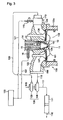
- FIG. 3 is a configuration diagram around the combustion chamber showing the configuration of a gas engine using such low-calorie gas as fuel.
- FIG. 3 is a configuration diagram around the combustion chamber showing the configuration of a gas engine using such low-calorie gas as fuel.
- an engine (gas engine) denoted by reference numeral 100 is a sub-chamber ignition type four-cycle gas engine using a spark plug, and a piston 102 and a cylinder fitted in a cylinder liner 102a so as to be slidable back and forth.
- a main combustion chamber 101 is defined between the lower surface of the head 105, the upper surface of the piston 102, and the inner surface of the cylinder liner 102a.
- the engine 100 includes an air supply port 103 connected to the main combustion chamber 101, an air supply valve 104 that opens and closes the air supply port 103, an exhaust port 106 connected to the main combustion chamber 101, and the exhaust port An exhaust valve 107 for opening and closing 106 is provided.
- the exhaust port 106 is connected to the turbine 108 of the exhaust turbocharger 130 via an exhaust pipe 118.
- the exhaust gas after driving the turbine 108 passes through the exhaust pipe 117 and enters the exhaust gas purification device 111 composed of a catalyst layer or the like. After being purified by the exhaust gas purification device 111, the exhaust gas is discharged into the atmosphere from the exhaust gas pipe 116. .
- the compressor 109 driven coaxially with the turbine 108 compresses the intake air, and the compressed air enters the gas mixer 110 through the air pipe 120.
- a low calorie gas having a low methane concentration of 50% or less, such as coal mine methane is stored in the low calorie gas supply source 123.
- the low-calorie gas passes through the main fuel gas pipe 121 to the gas amount adjusting valve 115, and the gas amount and the open / close period are adjusted by the gas amount adjusting valve 115 and enters the gas mixer 110.
- the gas mixer 110 premixes the air from the air pipe 120 and the low-calorie gas from the main fuel gas pipe 121 to generate a premixed gas, and the premixed gas is supplied to the air supply port 103 of the engine.
- the premixed gas reaches the supply valve 104 via the supply port 103, and is supplied into the main combustion chamber 101 by opening the supply valve 104.
- the sub chamber base 12 a is fixed to the cylinder head 105 from the upper surface by a base presser 14.
- a sub chamber 12 having a constant volume is formed in the sub chamber base 12a.
- a spark plug 13 is fixed to the upper portion of the sub chamber 12, and the gas in the sub chamber 12 is ignited by the spark plug 13.
- a joint 16 is screwed into the cap retainer 14, and one end of the joint 16 is connected to the low calorie gas supply source 123 through a fuel gas pipe 122 separated from the main fuel gas pipe 121, and the other end side is connected to the sub-calorie. It is connected to a fuel passage 15 that opens into the chamber 12.
- the low calorie gas from the low calorie gas supply source 123 enters the fuel passage 15 through the fuel gas pipe 122 and is ejected from the fuel passage 15 into the sub chamber 12. .
- the separated low calorie gas that has passed through the main fuel gas pipe 121 is adjusted in the gas amount and opening / closing period by the gas amount adjusting valve 115 and enters the gas mixer 110.
- the gas mixer 110 a premixed gas of low-calorie gas and air is generated as described above, and this premixed gas is introduced into the supply port 103 of the engine.
- the premixed gas reaches the air supply valve 104 via the air supply port 103 and is supplied into the main combustion chamber 101 by opening the air supply valve 104.
- Patent Document 1 Japanese Patent No. 36494719
- Patent Document 2 Japanese Patent Application Laid-Open No.
- 2000-8960 uses a first fuel that forms a lean air-fuel mixture and a second fuel that has a higher combustion speed and higher ignitability than the first fuel, and has a lean main combustion chamber. Means is provided for filling the sub-chamber with the second fuel with the air-fuel mixture.
- a low calorie gas engine using a low calorie gas having a low methane concentration of 50% or less as a fuel, injects the low calorie gas into the sub chamber and ignites it with a spark plug.
- An ignition flame generated by ignition combustion is ejected to the main combustion chamber through a communication hole connecting the sub chamber and the main combustion chamber, and is formed by a low calorie gas separated from the sub chamber side and sucked through the supply port
- the premixed gas in the main combustion chamber is combusted.
- gas engines such as coal mine methane, which use low calorie gas with a low methane concentration of 50% or less as fuel, use low calorie gas shown in A of FIG.
- the amount of heat generated is only about 30%, and in a normal state, it is not in a state where it can be ignited and burned by the spark plug.
- the first fuel forming the lean mixture and the second fuel having a higher combustion speed and higher ignitability than the first fuel are used, and the main combustion chamber is sub-chambered with the lean mixture.
- the first fuel that forms the lean mixture and the second fuel that has a higher burning rate and higher ignitability than the first fuel, and the sub-chamber with the lean mixture in the main combustion chamber Although means adapted to be filled with the second fuel is used, such means cannot be applied as it is to an engine using low calorie gas having a low methane concentration of 50% or less as fuel.
- the present invention improves the methane concentration and injects the low calorie gas into the sub chamber and ignites the gas engine, such as coal mine methane, which uses a low calorie gas having a methane concentration of 50% or less as fuel.
- An object of the present invention is to provide a gas engine using a low calorie gas fuel that can be ignited and burned by a plug. The present invention achieves such an object.
- a low calorie gas having a low methane concentration of 50% or less is used as fuel, an ignition plug is arranged in the sub chamber, and the low calorie gas is injected into the sub chamber.
- the ignition flame generated by the ignition combustion in the sub chamber is ejected to the main combustion chamber through the communication hole connecting the sub chamber and the main combustion chamber, and separated from the sub chamber side by the jet flame.
- PSA Pressure swing adsorption process
- a gas subjected to the PSA treatment is introduced into the sub chamber and ignited and burned by the spark plug.
- the low-calorie gas is branched into the main combustion low-calorie gas before being introduced into the PSA treatment apparatus, and the main-combustion low-calorie gas is adjusted through a gas amount adjustment valve. Then, the low-calorie gas for main combustion is introduced into a gas mixer, the premixed gas of the low-calorie gas and air is generated by the gas mixer, and the premixed gas is introduced into the supply port of the engine.
- a buffer tank for introducing the gas subjected to the PSA treatment and homogenizing the methane concentration of the gas is installed at the outlet of the PSA treatment apparatus.
- the present invention uses a low calorie gas having a low methane concentration of 50% or less as a fuel, arranges an ignition plug in the sub chamber, injects the low calorie gas into the sub chamber, and ignites with the ignition plug.
- the ignition flame generated by the ignition combustion in the sub chamber is ejected to the main combustion chamber through a communication hole connecting the sub chamber and the main combustion chamber, and separated from the sub chamber side by the ejected flame and sucked through the air supply port
- the low-calorie gas is carried into the TSA processor, and the TSA processor is about 200 from the low-calorie gas.
- TSA treatment Thermal swing adsorption treatment to obtain methane gas with high methane concentration by adsorbing and separating impurities and inert gas (other than methane gas) by raising the temperature at °C
- impurities and inert gas other than methane gas
- characterized by such a TSA process were subjected to gas that has been configured to ignite and burn at the spark plug is introduced the into sub-chamber.
- an exhaust gas introduction pipe for transmitting the exhaust gas of the gas engine is connected to the TSA processing apparatus, and the heat of the exhaust gas is used for the temperature raising process of the low calorie gas in the TSA processing apparatus.
- low-calorie gas in a gas engine using low-calorie gas fuel, low-calorie gas is carried into a PSA processing apparatus, and impurities and inert gases (other than methane gas) are adsorbed and separated from the low-calorie gas in the PSA processing apparatus.
- the pressure swing adsorption process (PSA process) for obtaining methane gas with a high methane concentration is performed, and the gas subjected to the PSA process is introduced into the sub chamber and ignited and burned with the spark plug.
- the low calorie gas (see FIG. 4) having a calorific value of only about 30% compared with the normal calorie gas engine is pressurized and adsorbed and separated through an adsorbent such as zeolite.
- 100% concentration of methane gas can be obtained. Since the amount of gas for generating an ignition flame in the auxiliary chamber of the engine is about 2% of methane, the 100% concentration of methane gas is sufficient, and such methane gas is ejected in the auxiliary chamber. Then, spark gas is discharged from the ignited methane gas by a spark plug at a predetermined time, and an ignition flame generated by the ignition combustion is ejected to the main combustion chamber through the communication hole.
- 100% concentration methane gas can be obtained from the low calorie gas by pressure swing adsorption processing (PSA processing), and this methane gas is ejected into the sub chamber, and the ignition plug
- PSA processing pressure swing adsorption processing
- the engine can be applied to an engine using a low calorie gas having a low methane concentration of 50% or less without deteriorating the ignition performance in the sub chamber.
- the low-calorie gas is branched before the introduction of the PSA treatment device to obtain a low-calorie gas for main combustion, the amount of the main-calorie low-calorie gas is adjusted through a gas amount adjustment valve, A low-calorie gas for combustion is introduced into a gas mixer, and the premixed gas of the low-calorie gas and air is generated by the gas mixer, and the premixed gas is introduced into an air supply port of the engine.
- 100% concentration methane gas is obtained from the low calorie gas by pressure swing adsorption processing (PSA processing), and this methane gas is injected into the sub chamber and sparked by the spark plug.
- PSA processing pressure swing adsorption processing
- the ignition performance in the sub chamber can be reliably obtained, so that the low-calorie gas can be introduced into a gas mixer to easily generate a premixed gas with air, That is, a lean mixed gas of combustible low calorie gas and air can be easily generated.
- a buffer tank is installed at the outlet of the PSA treatment apparatus to introduce the gas subjected to the PSA treatment and homogenize the methane concentration of the gas.
- the concentration of the unequal concentration of the 100% methane gas from the low calorie gas can be made uniform by passing it through the buffer tank, and the gas having a constant concentration can be supplied to the sub chamber.
- the low calorie gas in a gas engine using a low calorie gas fuel, the low calorie gas is carried into the TSA processing apparatus, and impurities and inert gas are increased by raising the temperature from the low calorie gas to about 200 ° C in the TSA processing apparatus.
- a thermal swing adsorption process (TSA process) is performed to adsorb and separate (other than methane gas) to obtain a methane gas having a high methane concentration, and the gas subjected to the TSA process is introduced into the sub chamber and ignited and burned by the spark plug. Because it was configured as In the TSA processing apparatus, a low calorie gas (see FIG.
- the exhaust gas introduction pipe for transmitting the exhaust gas of the gas engine is connected to the TSA processing apparatus, and the heat of the exhaust gas is used for the temperature raising process of the low calorie gas in the TSA processing apparatus.
- the energy of the exhaust gas can be used for the temperature rising process of the low calorie gas in the TSA processing apparatus, and the exhaust heat of the engine can be used effectively.
- FIG. 1 is a configuration diagram around a combustion chamber showing the configuration of a gas engine using low-calorie gas as fuel, showing a first embodiment of the present invention.
- FIG. 2 is a configuration diagram around a combustion chamber showing a configuration of a gas engine using low-calorie gas as fuel, showing a second embodiment of the present invention.
- FIG. 3 is a configuration diagram around a combustion chamber showing a configuration of a gas engine using low-calorie gas as fuel according to the prior art.
- FIG. 4 is a methane concentration comparison diagram between the low-calorie gas and the current gas.
- FIG. 1 is a configuration diagram around a combustion chamber showing a configuration of a gas engine using low-calorie gas as a fuel according to a first embodiment of the present invention.
- the fuel gas is a low calorie gas (see FIG. 4) such as coal mine methane, which has a low methane concentration of 50% or less and a calorific value of only 30%, and the low calorie gas is stored in the low calorie gas supply source 123.
- the outlet of the low calorie gas supply source 123 is connected to the PSA processing apparatus 1.
- the low calorie gas see FIG.
- PSA processing pressure swing adsorption processing for obtaining 100% methane gas is performed.
- the details of the operation in the PSA processing apparatus 1 are well known, and detailed description thereof is omitted.
- the gas subjected to the PSA treatment is provided with a buffer tank 2 at the outlet of the PSA treatment apparatus 1, and the gas subjected to the PSA treatment is introduced into the buffer tank 2 to homogenize the methane concentration of the gas.
- the non-uniform portion of the 100% methane gas concentration from the low calorie gas is made uniform by passing it through the buffer tank 2, and the constant concentration gas is supplied to the sub chamber 12 described later.
- the gas exiting the buffer tank 2 is connected to a fuel passage 15 of a joint 16 screwed into a cap retainer 14 through a fuel gas pipe 3, and the fuel passage 15 is perforated in the cap retainer 14 into the sub chamber 12.
- the sub chamber base 12 a of the sub chamber 12 is pressed and fixed to the cylinder head 105 from the upper surface by a base presser 14.
- a spark plug 13 is fixed to the upper part of the sub chamber 12, and the gas in the sub chamber 12 is ignited by the spark plug 13.
- the low calorie gas branched from the PSA processing apparatus 1 from the low calorie gas supply source 123 passes through the main fuel gas pipe 4 to the gas amount adjusting valve 115, and the gas amount adjusting valve 115 opens and closes the gas amount.
- the period is adjusted and the gas mixer 110 is entered.
- the gas mixer 110 premixes the compressed air from the compressor 109 through the air pipe 120 and the low calorie gas from the fuel gas pipe 4 to generate a premixed gas, and the premixed gas is supplied to the engine.
- the air supply port 103 is charged.
- the premixed gas reaches the supply valve 104 via the supply port 103 and is supplied into the main combustion chamber 101 by opening the supply valve 104.
- the low-calorie gas from the low-calorie gas supply source 123 is a low-calorie gas whose calorific value is only about 30% as compared with a normal calorie gas engine in the PSA processing apparatus 1 (see FIG. 4).
- PSA treatment pressure swing adsorption treatment
- the PSA-treated gas is introduced into the buffer tank 2 installed at the outlet of the PSA treatment apparatus 1, and the methane concentration of the gas is homogenized.
- the gas having a uniform methane concentration from the buffer tank 2 is restricted in passage area by the throttle valve 5 when passing through the fuel gas pipe 3, and then enters the fuel passage 15.
- the low calorie gas branched off from the low calorie gas supply source 123 and the PSA processing apparatus 1 passes through the main fuel gas pipe 4 to the gas amount adjusting valve 115, and the gas amount adjusting valve 115
- the gas mixer 110 is entered after the opening / closing period is adjusted.
- the gas mixer 110 premixes the compressed air from the compressor 109 through the air pipe 120 and the low-calorie gas from the fuel gas pipe 4 to generate a premixed gas.
- the air supply port 103 is charged.
- the premixed gas reaches the supply valve 104 via the supply port 103 and is supplied into the main combustion chamber 101 by opening the supply valve 104. Then, in the sub chamber 12, ignition and combustion are performed by spark discharge of the spark plug 13, and the generated ignition flame is ejected to the premixed gas in the main combustion chamber 101 through the communication hole 11.
- the premixed gas in the main combustion chamber 101 is combusted.
- the exhaust gas after combustion passes through the exhaust port 106 and is sent to the turbine 108 of the exhaust turbocharger 130 through the exhaust pipe 118.
- the amount of gas supplied to the sub chamber is about 2% of the whole, and the concentration of 100% for generating an ignition flame in the sub chamber 12 from the gas supplied of about 2%.
- the PSA processing apparatus 1 100% concentration methane gas can be obtained from the low calorie gas by pressure swing adsorption processing (PSA processing), and this methane gas is ejected into the sub chamber 12.
- PSA processing pressure swing adsorption processing
- spark plug 13 it can be applied to an engine using low calorie gas with a low methane concentration of 50% or less as fuel, without lowering the ignition performance in the sub chamber 12.
- the PSA processing apparatus 1 100% concentration methane gas is obtained from the low calorie gas by pressure swing adsorption processing (PSA processing), and this methane gas is jetted into the sub chamber 12.
- PSA processing pressure swing adsorption processing
- the spark plug 13 By performing spark discharge with the spark plug 13, it is easy to obtain ignition performance in the sub chamber, so even if low calorie gas is used as the main combustion gas, the ignition performance in the sub chamber 12 is ensured.
- the low calorie gas can be introduced into the gas mixer 110 to easily generate a premixed gas with air from the supercharger, that is, a dilute mixed gas of combustible low calorie gas and air can be easily produced. Can be generated.
- FIG. 2 is a configuration diagram around a combustion chamber showing a configuration of a gas engine using low-calorie gas as a fuel according to a second embodiment of the present invention.
- a thermal swing adsorption type process (TSA process) 6 is provided instead of the PSA processing apparatus 1 in the first embodiment. That is, in the second embodiment, the low calorie gas from the low calorie gas supply source 123 is carried into the TSA processing apparatus 6. That is, in the TSA processing apparatus 6, as described above, low calorie gas (see FIG. 4) having a calorific value of only about 30% as compared with a normal calorie gas engine is adsorbed by raising the temperature to about 200 ° C.
- a thermal swing adsorption process for obtaining 100% methane gas is performed.
- TSA process thermal swing adsorption process
- the buffer tank 2 installed at the outlet of the TSA processing apparatus 6 introduces the gas subjected to the TSA process and homogenizes the methane concentration of the gas.
- the concentration is made uniform by passing through the buffer tank 2, and a gas having a constant concentration is supplied to the sub chamber 12 described later.
- the gas exiting the buffer tank 2 is connected to the fuel passage 15 of the joint 16 screwed into the cap retainer 14 through the fuel gas pipe 3, and the fuel passage 15 is perforated in the cap retainer 14. There is a hole.
- the sub chamber base 12 a of the sub chamber 12 is pressed and fixed to the cylinder head 105 from the upper surface by a base presser 14.
- An ignition plug 13 is fixed to the upper portion of the sub chamber 12, and the sub chamber 12
- the gas in 12 is ignited.
- the exhaust gas from the gas engine processed by the exhaust gas purification device 111 is connected from the exhaust gas pipe 116 to the TSA processing device 6 through the exhaust gas introduction tube 9, and the TSA processing device is connected. 6, the heat of the exhaust gas from the exhaust gas pipe 116 is used for the temperature raising process of the low calorie gas.
- the heat of the exhaust gas may be taken from the upstream side of the exhaust gas purification device 111.
- the thermal energy of exhaust gas can be used for temperature rising process of the low calorie gas in TSA processor 6, exhaust heat of an engine can be used effectively.
- the amount of gas supplied to the sub chamber 12 of the engine 100 is about 2% of the total, and 100% for generating an ignition flame in the sub chamber 12 from this 2% supply gas. Since the concentration of methane gas is generated, even if the TSA treatment device 6 is installed, it is not necessary to greatly change the entire gas supply device, and the cost increase can be minimized.
- the TSA treatment device 6 can obtain 100% concentration of methane gas from the low calorie gas, and this methane gas is injected into the sub chamber 12 and sparked by the spark plug 13 at a predetermined time, and is generated by this ignition combustion.
- the ignited flame is ejected to the main combustion chamber 101 through the communication hole 11 so that the ignition combustion in the sub chamber 12 can be facilitated.
- Structures other than those described above are the same as in the first embodiment, and the same members are denoted by the same reference numerals.
- a gas engine such as coal mine methane, which uses a low calorie gas having a methane concentration of 50% or less as a fuel, injects the low calorie gas into the sub chamber with the methane concentration improved, and ignites and burns with the spark plug.
- a gas engine using a low calorie gas fuel can be provided.
Abstract
炭鉱メタン等の、メタン濃度が50%以下という低カロリーガスを燃料とするガスエンジンに、メタン濃度を向上させて低カロリーガスを副室内に噴射し点火プラグにて着火燃焼可能な、低カロリーガス燃料を用いたガスエンジンを提供する。メタン濃度が50%以下と低い低カロリーガスを燃料としたガスエンジンにおいて、低カロリーガスをPSA処理装置に搬入し、該PSA処理装置において前記低カロリーガスから不純物を吸着分離してメタン濃度の濃いメタンガスを得る圧力スイング吸着式処理(PSA処理)を施し、かかるPSA処理を施したガスを前記副室内に導入し前記点火プラグにて着火燃焼させるように構成したことを特徴とする。
Description
本発明は、炭鉱メタン等の、メタン濃度が50%以下と低い低カロリーガスを燃料とし、副室に点火プラグを配置し該低カロリーガスを副室内に噴射し前記点火プラグにて着火させて、かかる副室の着火燃焼により発生した着火火炎を、副室と主燃焼室を接続する連絡孔を通して該主燃焼室に噴出させて、該噴出火炎により、副室側と分離して給気ポートを通して吸入した低カロリーガスにより形成した主燃焼室の混合気を燃焼させる低カロリーガス燃料を用いたガスエンジンに関する。
炭鉱メタン等の、メタン濃度が50%以下と低い低カロリーガスを燃料とするガスエンジンは、該低カロリーガスを副室内に噴射し点火プラグにて着火させて、かかる副室の着火燃焼により発生した着火火炎を、前記副室と主燃焼室を接続する連絡孔を通して該主燃焼室に噴出させて、該噴出火炎により、前記副室側と分離して給気ポートを通して吸入した低カロリーガスにより形成した主燃焼室の混合気を燃焼させるように構成されている。
図3は、かかる低カロリーガスを燃料とするガスエンジンの構成を示す燃焼室周りの構成図である。
図3において、符号100で示されるエンジン(ガスエンジン)は、点火プラグを用いた副室点火式4サイクルガスエンジンであり、シリンダライナ102a内に往復摺動自在に嵌合されたピストン102、シリンダヘッド105の下面と前記ピストン102の上面とシリンダライナ102aの内面との間に区画形成される主燃焼室101を備えている。
また、前記エンジン100は、前記主燃焼室101に接続される給気ポート103、該給気ポート103を開閉する給気弁104、該主燃焼室101に接続される排気ポート106、該排気ポート106を開閉する排気弁107等を備えている。
前記排気ポート106は、排気管118を経て排気ターボ過給機130のタービン108に接続される。該タービン108を駆動した後の排ガスは排気管117を通って、触媒層等からなる排ガス浄化装置111に入り、該排ガス浄化装置111で浄化されてから、排ガス管116から大気中に排出される。
一方、該タービン108に同軸駆動されるコンプレッサ109は、吸入空気を圧縮し、圧縮空気は空気管120を通ってガスミキサー110に入る。
燃料ガスは、炭鉱メタン等の、メタン濃度が50%以下と低い低カロリーガスを使用し、該低カロリーガスが低カロリーガス供給源123に収納されている。
また、前記低カロリーガスは主燃料ガス管121を通して、ガス量調整弁115に至り、該ガス量調整弁115にてガス量及び開閉期間を調整されて、ガスミキサー110に入る。
該ガスミキサー110では、前記空気管120からの空気と前記主燃料ガス管121からの低カロリーガスとを予混合して予混合ガスを生成して、この予混合ガスをエンジンの給気ポート103に投入する。
そして、この予混合ガスは給気ポート103を経て給気弁104に達し、該給気弁104の開弁によって前記主燃焼室101内に供給されている。
副室口金12aは、口金押え14によりシリンダヘッド105に上面から固定されている。前記副室口金12a内には、一定容積を有する副室12が形成されている。
該副室12の上部には点火プラグ13が固定され、該点火プラグ13によって副室12内のガスに点火するようになっている。
また、前記口金押え14には継手16がねじ込まれ、該継手16は、一端側が前記主燃料ガス管121と分離した燃料ガス管122を通して前記低カロリーガス供給源123に接続され、他端側が副室12に開孔する燃料通路15に接続している。
燃焼時においては、前記のように、低カロリーガス供給源123からの低カロリーガスは、前記燃料ガス管122を通って、燃料通路15に入り該燃料通路15から副室12内に噴出される。この際に所定の時期に前記点火プラグ13によって火花放電され、この着火燃焼により発生した着火火炎が、前記連絡孔11を通して該主燃焼室101に噴出される。
一方、前記主燃料ガス管121を通った分離後の低カロリーガスは、ガス量調整弁115にてガス量及び開閉期間を調整されて、ガスミキサー110に入る。
前記ガスミキサー110では、前記のようにして、低カロリーガスと空気との予混合ガスが生成されて、この予混合ガスをエンジンの給気ポート103に投入する。この予混合ガスは給気ポート103を経て給気弁104に達し、該給気弁104の開弁によって前記主燃焼室101内に供給される。
一方、前記点火プラグ13によって火花放電され、この着火燃焼により発生した着火火炎が、前記連絡孔11を通して該主燃焼室101中の予混合ガスに噴出され、主燃焼室101のガスが燃焼される。
主燃焼室101にて燃焼した燃焼後の排ガスは排気ポート106を通り、排気管118を経て排気ターボ過給機130のタービン108に送られる。
尚、特許文献1(特許3649479号公報)には、点火用あるいは始動用の燃料ガスと通常の燃料ガスとを使い分ける手段が設けられている。
また、特許文献2(特開2000−8960号公報)は、希薄混合気を形成する第1燃料と第1燃料よりも燃焼速度が高く着火性の高い第2燃料を用い、主燃焼室を希薄混合気で副室を第2燃料で充填するようにした手段が設けられている。
しかしながら、前記従来技術には次のような解決すべき問題点がある。
即ち、前記のように、メタン濃度が50%以下と低い低カロリーガスを燃料とする低カロリーガスエンジンは、該低カロリーガスを副室内に噴射し点火プラグにて着火させて、かかる副室の着火燃焼により発生した着火火炎を、前記副室と主燃焼室を接続する連絡孔を通して該主燃焼室に噴出させて、前記副室側と分離して給気ポートを通して吸入した低カロリーガスにより形成した主燃焼室の予混合気を燃焼させるように構成されている。
しかしながら、炭鉱メタン等の、メタン濃度が50%以下と低い低カロリーガスを燃料とするガスエンジンは、図4のAに示す低カロリーガスを使用のように、通常のカロリーのガスエンジンBに比べて発熱量が30%程度しかなく、通常の状態では点火プラグにて着火燃焼できる状態にはない。
このため、前記特許文献2のように、希薄混合気を形成する第1燃料と第1燃料よりも燃焼速度が高く着火性の高い第2燃料を用い、主燃焼室を希薄混合気で副室を第2燃料で充填するようにした手段希薄混合気を形成する第1燃料と第1燃料より焼速度が高く着火性の高い第2燃料を用い、主燃焼室を希薄混合気で副室を第2燃料で充填するようにした手段が用いられているが、かかる手段は、メタン濃度が50%以下と低い低カロリーガスを燃料とするエンジンにはそのまま適用できない。
本発明はかかる従来技術の課題に鑑み、炭鉱メタン等の、メタン濃度が50%以下という低カロリーガスを燃料とするガスエンジンに、メタン濃度を向上させて低カロリーガスを副室内に噴射し点火プラグにて着火燃焼可能な、低カロリーガス燃料を用いたガスエンジンを提供することを目的とする。
本発明はかかる目的を達成するもので、メタン濃度が50%以下と低い低カロリーガスを燃料とし、副室に点火プラグを配置して該低カロリーガスを副室内に噴射し前記点火プラグにて着火させて、かかる副室の着火燃焼により発生した着火火炎を前記副室と主燃焼室を接続する連絡孔を通して該主燃焼室に噴出させ、該噴出火炎により、前記副室側と分離して給気ポートを通して吸入した低カロリーガスにより形成した主燃焼室の混合気を燃焼させる低カロリーガス燃料を用いたガスエンジンにおいて、
前記低カロリーガスをPSA処理装置に搬入し、該PSA処理装置において前記低カロリーガスから不純物および不活性ガス(メタンガス以外)を吸着分離してメタン濃度の濃いメタンガスを得る圧力スイング吸着式処理(PSA処理)を施し、かかるPSA処理を施したガスを前記副室内に導入し前記点火プラグにて着火燃焼させるように構成したことを特徴とする。
かかる発明において、好ましくは、前記低カロリーガスを前記PSA処理装置へ導入前に分岐して主燃焼用低カロリーガスとし、該主燃焼用低カロリーガスを、ガス量調整弁を通してガス量を調整し、次いで前記主燃焼用低カロリーガスをガスミキサーに導入して該ガスミキサーにて前記低カロリーガスと空気との予混合ガスを生成して、この予混合ガスをエンジンの給気ポートに投入する。
また、かかる発明において、好ましくは、前記PSA処理装置の出口に、前記PSA処理を施したガスを導入し該ガスのメタン濃度を均質化するバッファタンクを設置する。
また、本発明は、メタン濃度が50%以下と低い低カロリーガスを燃料とし、副室に点火プラグを配置して該低カロリーガスを副室内に噴射し前記点火プラグにて着火させて、かかる副室の着火燃焼により発生した着火火炎を前記副室と主燃焼室を接続する連絡孔を通して該主燃焼室に噴出させ、該噴出火炎により、前記副室側と分離して給気ポートを通して吸入した低カロリーガスにより形成した主燃焼室の混合気を燃焼させる低カロリーガス燃料を用いたガスエンジンにおいて、前記低カロリーガスをTSA処理装置に搬入し、TSA処理装置において前記低カロリーガスから約200℃の昇温により不純物および不活性ガス(メタンガス以外)を吸着分離してメタン濃度の濃いメタンガスを得る熱スイング吸着式処理(TSA処理)を施し、かかるTSA処理を施したガスを前記副室内に導入し前記点火プラグにて着火燃焼させるように構成したことを特徴とする。
また、かかる発明において、好ましくは、前記ガスエンジンの排ガスを伝達する排ガス導入管を前記TSA処理装置に接続し、該TSA処理装置において前記排ガスの熱を前記低カロリーガスの昇温処理に用いる。
本発明によれば、低カロリーガス燃料を用いたガスエンジンにおいて、低カロリーガスをPSA処理装置に搬入し、該PSA処理装置において低カロリーガスから不純物および不活性ガス(メタンガス以外)を吸着分離してメタン濃度の濃いメタンガスを得る圧力スイング吸着式処理(PSA処理)を施し、かかるPSA処理を施したガスを前記副室内に導入し前記点火プラグにて着火燃焼させるように構成したので、
PSA処理装置において、前記の通常のカロリーのガスエンジンに比べて発熱量が30%程度しかない低カロリーガス(図4参照)を、加圧してゼオライトのような吸着物質を通して、不純物を吸着分離することにより、100%濃度のメタンガスを得ることができる。
エンジンの副室内の着火火炎生成用のガス量はメタン量2%程度であるので、前記100%濃度のメタンガスで十分であり、かかるメタンガスが副室内において噴出される。
そしてこの噴出メタンガスに、所定の時期に点火プラグによって火花放電され、この着火燃焼により発生した着火火炎が、前記連絡孔を通して該主燃焼室に噴出される。
従って、本発明によれば、PSA処理装置において、圧力スイング吸着式処理(PSA処理)によって、低カロリーガスから100%濃度のメタンガスを得ることができ、このメタンガスを副室内に噴出し、点火プラグによって火花放電することにより、メタン濃度が50%以下と低い低カロリーガスを燃料とするエンジンにも、副室内での着火性能を低下することなく、適用することができる。
また、前記発明において、低カロリーガスをPSA処理装置導入前に分岐して主燃焼用低カロリーガスとし、該主燃焼用低カロリーガスを、ガス量調整弁を通してガス量を調整し、次いで前記主燃焼用低カロリーガスをガスミキサーに導入して該ガスミキサーにて前記低カロリーガスと空気との予混合ガスを生成して、この予混合ガスをエンジンの給気ポートに投入するように構成したので、
PSA処理装置において、圧力スイング吸着式処理(PSA処理)によって、低カロリーガスから100%濃度のメタンガスを得て、このメタンガスを副室内に噴出して点火プラグによって火花放電することにより、副室内での着火性能を得ることが容易にでき、
主燃焼用ガスとして低カロリーガスを用いても、前記副室内での着火性能が確実に得られるので、該低カロリーガスをガスミキサーに導入して空気との予混合ガスを容易に生成でき、つまり燃焼可能な低カロリーガスと空気との希薄混合ガスを容易に生成できる。
また、PSA処理装置の出口に、前記PSA処理を施したガスを導入し該ガスのメタン濃度を均質化するバッファタンクを設置するので、
PSA処理装置において低カロリーガスから100%濃度のメタンガスの濃度の不均一な部分を、バッファタンクを通すことにより濃度を均一化して、コンスタントな濃度のガスを副室に供給できる。
また、本発明によれば、低カロリーガス燃料を用いたガスエンジンにおいて、低カロリーガスをTSA処理装置に搬入し、TSA処理装置において低カロリーガスから約200℃の昇温により不純物および不活性ガス(メタンガス以外)を吸着分離してメタン濃度の濃いメタンガスを得る熱スイング吸着式処理(TSA処理)を施し、かかるTSA処理を施したガスを前記副室内に導入し前記点火プラグにて着火燃焼させるように構成したので、
TSA処理装置において、前記の通常のカロリーのガスエンジンに比べて発熱量が30%程度しかない低カロリーガス(図4参照)を、約200℃の昇温により不純物を吸着分離して、100%濃度のメタンガスを得ることができる。
エンジンの副室内の着火火炎生成用のガス量はメタン量2%程度であるので、前記100%濃度のメタンガスで十分であり、かかるメタンガスが副室内において噴出される。
そしてこの噴出メタンガスに、所定の時期に点火プラグによって火花放電され、この着火燃焼により発生した着火火炎が、前記連絡孔を通して該主燃焼室に噴出することにより、副室内での着火燃焼が容易にできる。
また、かかる発明において、前記ガスエンジンの排ガスを伝達する排ガス導入管を前記TSA処理装置に接続し、該TSA処理装置において前記排ガスの熱を前記低カロリーガスの昇温処理に用いるので、
排ガスのエネルギーを、TSA処理装置における低カロリーガスの昇温処理に用いることができ、エンジンの排熱を有効利用できる。
第1図は、本発明の第1実施例を示す低カロリーガスを燃料とするガスエンジンの構成を示す燃焼室周りの構成図である。
第2図は、本発明の第2実施例を示す低カロリーガスを燃料とするガスエンジンの構成を示す燃焼室周りの構成図である。
第3図は、従来技術に係る低カロリーガスを燃料とするガスエンジンの構成を示す燃焼室周りの構成図である。
第4図は、低カロリーガスと現状ガスとのメタン濃度比較図である。
第2図は、本発明の第2実施例を示す低カロリーガスを燃料とするガスエンジンの構成を示す燃焼室周りの構成図である。
第3図は、従来技術に係る低カロリーガスを燃料とするガスエンジンの構成を示す燃焼室周りの構成図である。
第4図は、低カロリーガスと現状ガスとのメタン濃度比較図である。
以下、本発明を図に示した実施例を用いて詳細に説明する。但し、この実施例に記載されている構成部品の寸法、材質、形状、その相対配置などは特に特定的な記載がない限り、この発明の範囲をそれのみに限定する趣旨ではなく、単なる説明例にすぎない。
図1は、本発明の第1実施例を示す低カロリーガスを燃料とするガスエンジンの構成を示す燃焼室周りの構成図である。
燃料ガスは、炭鉱メタン等の、メタン濃度が50%以下と低く発熱量が30%程度しかない低カロリーガス(図4参照)を使用し、該低カロリーガスが低カロリーガス供給源123に収納されている。
前記低カロリーガス供給源123の出口は、PSA処理装置1に接続されている。
該PSA処理装置1においては、通常のカロリーのガスエンジンに比べて発熱量が30%程度しかない低カロリーガス(図4参照)を、加圧してゼオライトのような吸着物質を通して、不純物を吸着分離することにより、100%濃度のメタンガスを得る圧力スイング吸着式処理(PSA処理)を施す。尚、PSA処理装置1での作動の詳細は公知であるので、詳細な説明は省略する。
かかるPSA処理を施したガスは、PSA処理装置1の出口にバッファタンク2が設置され、該バッファタンク2では前記PSA処理を施したガスを導入し、該ガスのメタン濃度を均質化している。
即ち、PSA処理装置1において低カロリーガスから100%濃度のメタンガスの濃度の不均一な部分を、バッファタンク2を通すことにより濃度を均一化して、コンスタントな濃度のガスを後述する副室12に供給できる。
前記バッファタンク2を出たガスは、燃料ガス管3を通して、口金押え14にねじ込まれた継手16の燃料通路15に接続され、該燃料通路15は前記口金押え14に穿孔されて副室12に開孔している。
前記副室12の副室口金12aは、口金押え14によって、シリンダヘッド105に上面から押し付け固定されている。
前記副室12の上部には、点火プラグ13が固定され、該点火プラグ13によって副室12内のガスに点火するようになっている。
一方、低カロリーガス供給源123から、前記PSA処理装置1と分岐した低カロリーガスは、主燃料ガス管4を通して、ガス量調整弁115に通り、該ガス量調整弁115にてガス量及び開閉期間を調整されて、ガスミキサー110に入るようになっている。
該ガスミキサー110では、前記コンプレッサ109から空気管120を経た圧縮空気と、前記燃料ガス管4からの低カロリーガスとを予混合して予混合ガスを生成して、この予混合ガスをエンジンの給気ポート103に投入する。
そして、この予混合ガスは給気ポート103を経て給気弁104に達し、該給気弁104の開弁によって前記主燃焼室101内に供給されている。
次に前記エンジン100の燃焼時の作動について説明する。
前記のように、低カロリーガス供給源123からの低カロリーガスは、前記PSA処理装置1において、通常のカロリーのガスエンジンに比べて発熱量が30%程度しかない低カロリーガス(図4参照)を、加圧してゼオライトのような吸着物質を通して、不純物を吸着分離することにより、100%濃度のメタンガスを得る圧力スイング吸着式処理(PSA処理)を施す。
かかるPSA処理を施したガスは、PSA処理装置1の出口に設置されたバッファタンク2では前記PSA処理を施したガスを導入し、該ガスのメタン濃度を均質化する。
前記バッファタンク2からのメタン濃度が均質化されたガスは、前記燃料ガス管3を通る際に絞り弁5により通路面積を規制されてから、燃料通路15に入り、該燃料通路15から副室12内に噴出される。
この際に所定の時期に、前記点火プラグ13によって火花放電され、この着火燃焼により発生した着火火炎が、前記連絡孔11を通して該主燃焼室101に噴出される。
一方、前記低カロリーガス供給源123から、前記PSA処理装置1と分岐した低カロリーガスは、主燃料ガス管4を通して、ガス量調整弁115に通り、該ガス量調整弁115にてガス量及び開閉期間を調整されてから、ガスミキサー110に入る。
該ガスミキサー110では、前記コンプレッサ109から空気管120を経た圧縮空気と、前記燃料ガス管4からの低カロリーガスとを予混合して予混合ガスを生成して、この予混合ガスをエンジンの給気ポート103に投入する。
そして、この予混合ガスは給気ポート103を経て給気弁104に達し、該給気弁104の開弁によって前記主燃焼室101内に供給されている。
そして、前記副室12内において、点火プラグ13の火花放電によって着火燃焼し、発生した着火火炎が、前記連絡孔11を通して該主燃焼室101中の予混合ガスに噴出され、かかる噴出ガスにより、主燃焼室101の予混合ガスが燃焼される。
燃焼後の排ガスは排気ポート106を通り、排気管118を経て排気ターボ過給機130のタービン108に送られる。
以上のように、かかる実施例によれば、副室向け供給ガス量は全体の2%程度であり、この2%程度の供給ガスから副室12内の着火火炎生成用のための100%濃度のメタンガスが生成されるため、PSA処理装置1を設置してもガス供給装置全体を大きく変更する必要がなくコストアップを最小限に抑えることができる。
また、かかる実施例によれば、PSA処理装置1において、圧力スイング吸着式処理(PSA処理)によって、低カロリーガスから100%濃度のメタンガスを得ることができ、このメタンガスを副室12内に噴出し、点火プラグ13によって火花放電することにより、メタン濃度が50%以下と低い低カロリーガスを燃料とするエンジンにも、副室12内での着火性能を低下することなく、適用することができる。
また、かかる実施例によれば、PSA処理装置1において、圧力スイング吸着式処理(PSA処理)によって、低カロリーガスから100%濃度のメタンガスを得て、このメタンガスを副室12内に噴出して点火プラグ13によって火花放電することにより、副室内での着火性能を得ることが容易にできるので、主燃焼用ガスとして低カロリーガスを用いても、前記副室12内での着火性能が確実に得られるので、該低カロリーガスをガスミキサー110に導入して過給機からの空気との予混合ガスを容易に生成でき、つまり燃焼可能な低カロリーガスと空気との希薄混合ガスを容易に生成できる。
図2は、本発明の第2実施例を示す低カロリーガスを燃料とするガスエンジンの構成を示す燃焼室周りの構成図である。
この第2実施例においては、前記第1実施例における、PSA処理装置1に変えて、熱スイング吸着式処理(TSA処理)6を設けている。
即ち、第2実施例においては、低カロリーガス供給源123からの低カロリーガスをTSA処理装置6に搬入している。
即ち、TSA処理装置6において、前記のように、通常のカロリーのガスエンジンに比べて発熱量が30%程度しかない低カロリーガス(図4参照)を、約200℃の昇温により不純物を吸着分離して、100%濃度のメタンガスを得る熱スイング吸着式処理(TSA処理)を施す。尚、TSA処理装置6での作動の詳細は公知であるので、詳細な説明は省略する。
そして、前記第1実施例と同様に、TSA処理装置6の出口に設置されたバッファタンク2では、前記TSA処理を施したガスを導入し、該ガスのメタン濃度を均質化している。該バッファタンク2を通すことにより濃度を均一化して、コンスタントな濃度のガスを後述する副室12に供給している。
前記バッファタンク2を出たガスは、燃料ガス管3を通して、口金押え14にねじ込まれた継手16の燃料通路15に接続され、該燃料通路15は前記口金押え14に穿孔されて、副室12に開孔している。
前記副室12の副室口金12aは、口金押え14によって、シリンダヘッド105に上面から押し付け固定されている
前記副室12の上部には、点火プラグ13が固定され、該点火プラグ13によって副室12内のガスに点火するようになっている。
また、かかる第2実施例においては、前記ガスエンジンの排ガスを排ガス浄化装置111で処理した後の排ガス管116から、排ガス導入管9を介して前記TSA処理装置6に接続し、該TSA処理装置6において、前記排ガス管116からの排ガスの熱を前記低カロリーガスの昇温処理に用いている。尚、前記排ガスの熱は排ガス浄化装置111の上流側から取り出しても良い。
このようにすれば、排ガスの熱エネルギーを、TSA処理装置6における低カロリーガスの昇温処理に用いることができるので、エンジンの排熱を有効利用できる。
かかる第2実施例によれば、エンジン100の副室12向け供給ガス量は全体の2%程度であり、この2%程度の供給ガスから副室12内の着火火炎生成用のための100%濃度のメタンガスが生成されるため、TSA処理装置6を設置してもガス供給装置全体を大きく変更する必要がなくコストアップを最小限に抑えることができる。
また、TSA処理装置6によって低カロリーガスから100%濃度のメタンガスを得ることができ、このメタンガスを副室12内に噴出し、所定の時期に点火プラグ13によって火花放電され、この着火燃焼により発生した着火火炎が、前記連絡孔11を通して該主燃焼室101に噴出することにより、副室12内での着火燃焼が容易にできる。
前記以外の構成は、前記第1実施例と同様であり、これと同一の部材は同一の符号で示す。
本発明によれば、炭鉱メタン等の、メタン濃度が50%以下という低カロリーガスを燃料とするガスエンジンに、メタン濃度を向上させて低カロリーガスを副室内に噴射し点火プラグにて着火燃焼可能な、低カロリーガス燃料を用いたガスエンジンを提供できる。
Claims (5)
- メタン濃度が50%以下と低い低カロリーガスを燃料とし、副室に点火プラグを配置して該低カロリーガスを副室内に噴射し前記点火プラグにて着火させて、かかる副室の着火燃焼により発生した着火火炎を前記副室と主燃焼室を接続する連絡孔を通して該主燃焼室に噴出させ、該噴出火炎により、前記副室側と分離して給気ポートを通して吸入した低カロリーガスにより形成した主燃焼室の混合気を燃焼させる低カロリーガス燃料を用いたガスエンジンにおいて、
前記低カロリーガスをPSA処理装置に搬入し、該PSA処理装置において前記低カロリーガスから不純物および不活性ガス(メタンガス以外)を吸着分離してメタン濃度の濃いメタンガスを得る圧力スイング吸着式処理(PSA処理)を施し、かかるPSA処理を施したガスを前記副室内に導入し前記点火プラグにて着火燃焼させるように構成したことを特徴とする低カロリーガス燃料を用いたガスエンジン。 - 前記低カロリーガスを前記PSA処理装置へ導入前に分岐して主燃焼用低カロリーガスとし、該主燃焼用低カロリーガスを、ガス量調整弁を通してガス量を調整し、次いで前記主燃焼用低カロリーガスをガスミキサーに導入して該ガスミキサーにて前記低カロリーガスと空気との予混合ガスを生成して、この予混合ガスをエンジンの給気ポートに投入することを特徴とする請求項1記載の低カロリーガス燃料を用いたガスエンジン。
- 前記PSA処理装置の出口に、前記PSA処理を施したガスを導入し該ガスのメタン濃度を均質化するバッファタンクを設置したことを特徴とする請求項1記載の低カロリーガス燃料を用いたガスエンジン。
- メタン濃度が50%以下と低い低カロリーガスを燃料とし、副室に点火プラグを配置して該低カロリーガスを副室内に噴射し前記点火プラグにて着火させて、かかる副室の着火燃焼により発生した着火火炎を前記副室と主燃焼室を接続する連絡孔を通して該主燃焼室に噴出させ、該噴出火炎により、前記副室側と分離して給気ポートを通して吸入した低カロリーガスにより形成した主燃焼室の混合気を燃焼させる低カロリーガス燃料を用いたガスエンジンにおいて、
前記低カロリーガスをTSA処理装置に搬入し、TSA処理装置において前記低カロリーガスから約200℃の昇温により不純物および不活性ガス(メタンガス以外)を吸着分離してメタン濃度の濃いメタンガスを得る熱スイング吸着式処理(TSA処理)を施し、かかるTSA処理を施したガスを前記副室内に導入し前記点火プラグにて着火燃焼させるように構成したことを特徴とする低カロリーガス燃料を用いたガスエンジン。 - 前記ガスエンジンの排ガスを伝達する排ガス導入管を前記TSA処理装置に接続し、該TSA処理装置において前記排ガスの熱を前記低カロリーガスの昇温処理に用いることを特徴とする請求項4記載の低カロリーガス燃料を用いたガスエンジン。
Priority Applications (2)
| Application Number | Priority Date | Filing Date | Title |
|---|---|---|---|
| CN2009801060933A CN101952581B (zh) | 2008-10-10 | 2009-01-28 | 使用低热值气体燃料的燃气发动机 |
| EP09819017.6A EP2246551B1 (en) | 2008-10-10 | 2009-01-28 | Gas engine using low calorie gas fuel |
Applications Claiming Priority (2)
| Application Number | Priority Date | Filing Date | Title |
|---|---|---|---|
| JP2008263924A JP2010090860A (ja) | 2008-10-10 | 2008-10-10 | 低カロリーガス燃料を用いたガスエンジン |
| JP2008-263924 | 2008-10-10 |
Publications (1)
| Publication Number | Publication Date |
|---|---|
| WO2010041478A1 true WO2010041478A1 (ja) | 2010-04-15 |
Family
ID=42100438
Family Applications (1)
| Application Number | Title | Priority Date | Filing Date |
|---|---|---|---|
| PCT/JP2009/051811 WO2010041478A1 (ja) | 2008-10-10 | 2009-01-28 | 低カロリーガス燃料を用いたガスエンジン |
Country Status (4)
| Country | Link |
|---|---|
| EP (1) | EP2246551B1 (ja) |
| JP (1) | JP2010090860A (ja) |
| CN (1) | CN101952581B (ja) |
| WO (1) | WO2010041478A1 (ja) |
Cited By (4)
| Publication number | Priority date | Publication date | Assignee | Title |
|---|---|---|---|---|
| CN101858245A (zh) * | 2010-04-28 | 2010-10-13 | 大连理工大学 | 大型气体燃料发动机燃烧系统 |
| CN103573476A (zh) * | 2012-07-26 | 2014-02-12 | 广西玉柴机器股份有限公司 | 燃气预喷射装置 |
| JP2019518005A (ja) * | 2016-04-28 | 2019-06-27 | メルク パテント ゲゼルシャフト ミット ベシュレンクテル ハフツングMerck Patent Gesellschaft mit beschraenkter Haftung | ピペリジニル誘導体 |
| CN113279729A (zh) * | 2021-06-10 | 2021-08-20 | 中国矿业大学(北京) | 一种堵漏提浓的瓦斯抽采方法 |
Families Citing this family (14)
| Publication number | Priority date | Publication date | Assignee | Title |
|---|---|---|---|---|
| WO2012131990A1 (ja) * | 2011-03-31 | 2012-10-04 | 三菱重工業株式会社 | ガスエンジンの制御装置 |
| CN102322332B (zh) * | 2011-06-20 | 2013-03-27 | 奇瑞汽车股份有限公司 | 一种cng发动机燃烧室结构及其燃料喷射方法 |
| AT511734B1 (de) * | 2011-07-20 | 2016-02-15 | Ge Jenbacher Gmbh & Co Ohg | Verfahren zum betreiben einer stationären kraftanlage |
| JP5916372B2 (ja) * | 2011-12-22 | 2016-05-11 | 大阪瓦斯株式会社 | 副室式エンジン |
| DK2890886T3 (da) * | 2012-08-30 | 2020-07-20 | Enhanced Energy Group LLC | Cyklisk stempelmotoreffektsystem |
| DE102012021778B4 (de) | 2012-11-06 | 2016-03-10 | Mtu Friedrichshafen Gmbh | Gemischaufgeladener Gasmotor und Verfahren zur Kompensation von Liefergradabweichungen in einem gemischaufgeladenen Gasmotor |
| KR102114527B1 (ko) * | 2014-02-26 | 2020-05-22 | 얀마 가부시키가이샤 | 엔진 장치 |
| EP2998539B1 (en) | 2014-09-19 | 2019-09-04 | Caterpillar Motoren GmbH & Co. KG | Ignition system for internal combustion engines |
| DE102016112537A1 (de) * | 2016-07-08 | 2018-01-11 | Man Diesel & Turbo Se | Gasmotor und Verfahren zum Betreiben desselben |
| CN106224087B (zh) * | 2016-07-30 | 2019-11-26 | 石家庄新华能源环保科技股份有限公司 | 一种应用高压低燃值气体燃料的发动机 |
| CN110410234A (zh) * | 2019-06-29 | 2019-11-05 | 潍柴动力股份有限公司 | 天然气直喷装置及具有其的双喷射分层燃烧系统 |
| JP2022107914A (ja) * | 2021-01-12 | 2022-07-25 | 日立Astemo株式会社 | 燃焼制御システム及び燃焼制御方法 |
| CN112901337B (zh) * | 2021-04-02 | 2022-03-22 | 贵州华气动力有限责任公司 | 一种大功率低浓度瓦斯发动机及其供气方法 |
| CN113047940B (zh) * | 2021-04-02 | 2022-03-22 | 贵州华气动力有限责任公司 | 一种利用低浓度瓦斯的预燃室 |
Citations (10)
| Publication number | Priority date | Publication date | Assignee | Title |
|---|---|---|---|---|
| JPS61255995A (ja) * | 1985-05-09 | 1986-11-13 | Kansai Coke & Chem Co Ltd | 高カロリ−ガスの製造法 |
| JPS63178196A (ja) * | 1987-01-18 | 1988-07-22 | Kansai Coke & Chem Co Ltd | 高カロリ−ガスの製造法 |
| JPH05321670A (ja) * | 1992-05-18 | 1993-12-07 | Yanmar Diesel Engine Co Ltd | 副室式希薄燃焼ガス機関 |
| JPH0639233A (ja) * | 1990-01-10 | 1994-02-15 | Uop Inc | 圧力スイング段階の前に温度スイング段階を採用して水素および炭化水素を回収する集合化吸着方法 |
| JP2000008960A (ja) | 1998-06-19 | 2000-01-11 | Osaka Gas Co Ltd | 副室式内燃機関 |
| JP2003253274A (ja) * | 2002-03-05 | 2003-09-10 | Mitsui Eng & Shipbuild Co Ltd | バイオマスガス化装置および発電システム |
| JP2004154761A (ja) * | 2002-07-19 | 2004-06-03 | Air Products & Chemicals Inc | 供給ガスの処理方法及び装置 |
| JP3649479B2 (ja) | 1995-07-21 | 2005-05-18 | 三菱重工業株式会社 | 希薄燃焼ガスエンジンの始動装置 |
| JP2007077870A (ja) * | 2005-09-14 | 2007-03-29 | Nissan Motor Co Ltd | 燃料改質方法及び燃料改質装置 |
| JP2008240624A (ja) * | 2007-03-27 | 2008-10-09 | Nissan Motor Co Ltd | 燃料改質機構付き内燃機関 |
Family Cites Families (4)
| Publication number | Priority date | Publication date | Assignee | Title |
|---|---|---|---|---|
| JP2004124847A (ja) * | 2002-10-03 | 2004-04-22 | Nippon Steel Corp | 水素含有ガスの処理システムおよび水素含有ガスの処理方法 |
| JP2005240586A (ja) * | 2004-02-24 | 2005-09-08 | Nippon Steel Corp | 低温プラズマ装置とガスエンジンとの複合システム、およびエネルギー生成方法 |
| US7363883B2 (en) * | 2004-03-19 | 2008-04-29 | Mitsubishi Heavy Industries, Ltd. | Gas engine electric power generating system effectively utilizing greenhouse gas emission credit |
| GB2413824A (en) * | 2004-05-07 | 2005-11-09 | Statoil Asa | Operating diesel-cycle i.c. engines on gaseous fuels with ignition-improvers |
-
2008
- 2008-10-10 JP JP2008263924A patent/JP2010090860A/ja not_active Withdrawn
-
2009
- 2009-01-28 WO PCT/JP2009/051811 patent/WO2010041478A1/ja active Application Filing
- 2009-01-28 CN CN2009801060933A patent/CN101952581B/zh not_active Expired - Fee Related
- 2009-01-28 EP EP09819017.6A patent/EP2246551B1/en not_active Not-in-force
Patent Citations (10)
| Publication number | Priority date | Publication date | Assignee | Title |
|---|---|---|---|---|
| JPS61255995A (ja) * | 1985-05-09 | 1986-11-13 | Kansai Coke & Chem Co Ltd | 高カロリ−ガスの製造法 |
| JPS63178196A (ja) * | 1987-01-18 | 1988-07-22 | Kansai Coke & Chem Co Ltd | 高カロリ−ガスの製造法 |
| JPH0639233A (ja) * | 1990-01-10 | 1994-02-15 | Uop Inc | 圧力スイング段階の前に温度スイング段階を採用して水素および炭化水素を回収する集合化吸着方法 |
| JPH05321670A (ja) * | 1992-05-18 | 1993-12-07 | Yanmar Diesel Engine Co Ltd | 副室式希薄燃焼ガス機関 |
| JP3649479B2 (ja) | 1995-07-21 | 2005-05-18 | 三菱重工業株式会社 | 希薄燃焼ガスエンジンの始動装置 |
| JP2000008960A (ja) | 1998-06-19 | 2000-01-11 | Osaka Gas Co Ltd | 副室式内燃機関 |
| JP2003253274A (ja) * | 2002-03-05 | 2003-09-10 | Mitsui Eng & Shipbuild Co Ltd | バイオマスガス化装置および発電システム |
| JP2004154761A (ja) * | 2002-07-19 | 2004-06-03 | Air Products & Chemicals Inc | 供給ガスの処理方法及び装置 |
| JP2007077870A (ja) * | 2005-09-14 | 2007-03-29 | Nissan Motor Co Ltd | 燃料改質方法及び燃料改質装置 |
| JP2008240624A (ja) * | 2007-03-27 | 2008-10-09 | Nissan Motor Co Ltd | 燃料改質機構付き内燃機関 |
Cited By (5)
| Publication number | Priority date | Publication date | Assignee | Title |
|---|---|---|---|---|
| CN101858245A (zh) * | 2010-04-28 | 2010-10-13 | 大连理工大学 | 大型气体燃料发动机燃烧系统 |
| CN103573476A (zh) * | 2012-07-26 | 2014-02-12 | 广西玉柴机器股份有限公司 | 燃气预喷射装置 |
| JP2019518005A (ja) * | 2016-04-28 | 2019-06-27 | メルク パテント ゲゼルシャフト ミット ベシュレンクテル ハフツングMerck Patent Gesellschaft mit beschraenkter Haftung | ピペリジニル誘導体 |
| JP7028792B2 (ja) | 2016-04-28 | 2022-03-02 | メルク パテント ゲゼルシャフト ミット ベシュレンクテル ハフツング | ピペリジニル誘導体 |
| CN113279729A (zh) * | 2021-06-10 | 2021-08-20 | 中国矿业大学(北京) | 一种堵漏提浓的瓦斯抽采方法 |
Also Published As
| Publication number | Publication date |
|---|---|
| CN101952581A (zh) | 2011-01-19 |
| CN101952581B (zh) | 2013-09-04 |
| JP2010090860A (ja) | 2010-04-22 |
| EP2246551B1 (en) | 2017-11-15 |
| EP2246551A1 (en) | 2010-11-03 |
| EP2246551A4 (en) | 2015-10-14 |
Similar Documents
| Publication | Publication Date | Title |
|---|---|---|
| WO2010041478A1 (ja) | 低カロリーガス燃料を用いたガスエンジン | |
| US6739289B2 (en) | Method and apparatus for providing a hydrogen enriched fuel to combustion prechamber | |
| US4181100A (en) | Internal combustion engine operated on injected fuel supplemented with hydrogen | |
| SU579931A3 (ru) | Способ работы двигател внутреннего сгорани с принудительным зажиганием | |
| JP2009236111A (ja) | 内燃機関及び内燃機関の運転方法 | |
| BR0314989A (pt) | Método de operação de um motor de combustão interna a gás, método de operação de um motor de combustão interna, aparelho de recirculação de gás de exaustão para uso em um motor de combustão interna de injeção direta a gás, motor de combustão interna a gás, motor de combustão interna | |
| KR101745021B1 (ko) | 가솔린/디젤 연료 혼합 압축 착화 연소 엔진의 이지알 제어 시스템 및 그 방법 | |
| US4079703A (en) | Internal combustion engine operated on injected fuel supplemented with hydrogen | |
| EP1143126A3 (de) | Vorkammer-Zündkerze mit Zusatzkraftstoff zur Entflammung sehr magerer Kraftstoff-Luft-Gemische, insbesondere für Gasmotoren | |
| GB1454280A (en) | Combustible mixture supply system | |
| ATE462075T1 (de) | Verfahren zum betrieb eines gasmotors | |
| JP5765819B2 (ja) | 2サイクルガスエンジン | |
| WO2016161518A1 (en) | Ignition apparatus and method for a premixed charge in a gaseous-fuelled engine | |
| EP1026800A3 (en) | Directed jet spark plug | |
| JP4719797B2 (ja) | 内燃機関運転方法 | |
| RU2508462C2 (ru) | Способ управления работой холодного двигателя внутреннего сгорания в период его пуска и прогрева | |
| JP3218323B2 (ja) | 予混合気圧縮着火エンジンにおける燃料の着火性改善方法 | |
| JP2747988B2 (ja) | 内燃機関の燃焼制御方法及び装置 | |
| US20170101967A1 (en) | Prechamber internal reformer catalyst | |
| JP2016006325A (ja) | 2サイクルガスエンジン及び2サイクルガスエンジン用の燃料ガス噴射システム | |
| JP2016089841A (ja) | ガスエンジンを起動するための方法 | |
| JPH084533A (ja) | ガス燃料エンジン | |
| JP2020159238A (ja) | デュアルフューエルエンジン | |
| CN214424582U (zh) | 一种大缸径低热值燃气内燃机独立进气预燃室 | |
| JPH10205397A (ja) | 吸気管燃料噴射圧縮着火エンジンにおける燃料の着火性改善方法 |
Legal Events
| Date | Code | Title | Description |
|---|---|---|---|
| WWE | Wipo information: entry into national phase |
Ref document number: 200980106093.3 Country of ref document: CN |
|
| 121 | Ep: the epo has been informed by wipo that ep was designated in this application |
Ref document number: 09819017 Country of ref document: EP Kind code of ref document: A1 |
|
| REEP | Request for entry into the european phase |
Ref document number: 2009819017 Country of ref document: EP |
|
| WWE | Wipo information: entry into national phase |
Ref document number: 2009819017 Country of ref document: EP |
|
| NENP | Non-entry into the national phase |
Ref country code: DE |