WO2010024274A1 - 樹脂積層体の製造方法 - Google Patents
樹脂積層体の製造方法 Download PDFInfo
- Publication number
- WO2010024274A1 WO2010024274A1 PCT/JP2009/064832 JP2009064832W WO2010024274A1 WO 2010024274 A1 WO2010024274 A1 WO 2010024274A1 JP 2009064832 W JP2009064832 W JP 2009064832W WO 2010024274 A1 WO2010024274 A1 WO 2010024274A1
- Authority
- WO
- WIPO (PCT)
- Prior art keywords
- layer
- film
- resin
- cured coating
- coating layer
- Prior art date
- Legal status (The legal status is an assumption and is not a legal conclusion. Google has not performed a legal analysis and makes no representation as to the accuracy of the status listed.)
- Ceased
Links
Classifications
-
- B—PERFORMING OPERATIONS; TRANSPORTING
- B32—LAYERED PRODUCTS
- B32B—LAYERED PRODUCTS, i.e. PRODUCTS BUILT-UP OF STRATA OF FLAT OR NON-FLAT, e.g. CELLULAR OR HONEYCOMB, FORM
- B32B27/00—Layered products comprising a layer of synthetic resin
-
- B—PERFORMING OPERATIONS; TRANSPORTING
- B32—LAYERED PRODUCTS
- B32B—LAYERED PRODUCTS, i.e. PRODUCTS BUILT-UP OF STRATA OF FLAT OR NON-FLAT, e.g. CELLULAR OR HONEYCOMB, FORM
- B32B7/00—Layered products characterised by the relation between layers; Layered products characterised by the relative orientation of features between layers, or by the relative values of a measurable parameter between layers, i.e. products comprising layers having different physical, chemical or physicochemical properties; Layered products characterised by the interconnection of layers
- B32B7/04—Interconnection of layers
- B32B7/06—Interconnection of layers permitting easy separation
-
- B—PERFORMING OPERATIONS; TRANSPORTING
- B32—LAYERED PRODUCTS
- B32B—LAYERED PRODUCTS, i.e. PRODUCTS BUILT-UP OF STRATA OF FLAT OR NON-FLAT, e.g. CELLULAR OR HONEYCOMB, FORM
- B32B27/00—Layered products comprising a layer of synthetic resin
- B32B27/06—Layered products comprising a layer of synthetic resin as the main or only constituent of a layer, which is next to another layer of the same or of a different material
-
- B—PERFORMING OPERATIONS; TRANSPORTING
- B32—LAYERED PRODUCTS
- B32B—LAYERED PRODUCTS, i.e. PRODUCTS BUILT-UP OF STRATA OF FLAT OR NON-FLAT, e.g. CELLULAR OR HONEYCOMB, FORM
- B32B27/00—Layered products comprising a layer of synthetic resin
- B32B27/06—Layered products comprising a layer of synthetic resin as the main or only constituent of a layer, which is next to another layer of the same or of a different material
- B32B27/08—Layered products comprising a layer of synthetic resin as the main or only constituent of a layer, which is next to another layer of the same or of a different material of synthetic resin
-
- B—PERFORMING OPERATIONS; TRANSPORTING
- B32—LAYERED PRODUCTS
- B32B—LAYERED PRODUCTS, i.e. PRODUCTS BUILT-UP OF STRATA OF FLAT OR NON-FLAT, e.g. CELLULAR OR HONEYCOMB, FORM
- B32B27/00—Layered products comprising a layer of synthetic resin
- B32B27/16—Layered products comprising a layer of synthetic resin specially treated, e.g. irradiated
-
- B—PERFORMING OPERATIONS; TRANSPORTING
- B32—LAYERED PRODUCTS
- B32B—LAYERED PRODUCTS, i.e. PRODUCTS BUILT-UP OF STRATA OF FLAT OR NON-FLAT, e.g. CELLULAR OR HONEYCOMB, FORM
- B32B38/00—Ancillary operations in connection with laminating processes
-
- B—PERFORMING OPERATIONS; TRANSPORTING
- B32—LAYERED PRODUCTS
- B32B—LAYERED PRODUCTS, i.e. PRODUCTS BUILT-UP OF STRATA OF FLAT OR NON-FLAT, e.g. CELLULAR OR HONEYCOMB, FORM
- B32B7/00—Layered products characterised by the relation between layers; Layered products characterised by the relative orientation of features between layers, or by the relative values of a measurable parameter between layers, i.e. products comprising layers having different physical, chemical or physicochemical properties; Layered products characterised by the interconnection of layers
- B32B7/04—Interconnection of layers
- B32B7/12—Interconnection of layers using interposed adhesives or interposed materials with bonding properties
-
- B—PERFORMING OPERATIONS; TRANSPORTING
- B32—LAYERED PRODUCTS
- B32B—LAYERED PRODUCTS, i.e. PRODUCTS BUILT-UP OF STRATA OF FLAT OR NON-FLAT, e.g. CELLULAR OR HONEYCOMB, FORM
- B32B2255/00—Coating on the layer surface
-
- B—PERFORMING OPERATIONS; TRANSPORTING
- B32—LAYERED PRODUCTS
- B32B—LAYERED PRODUCTS, i.e. PRODUCTS BUILT-UP OF STRATA OF FLAT OR NON-FLAT, e.g. CELLULAR OR HONEYCOMB, FORM
- B32B2307/00—Properties of the layers or laminate
- B32B2307/40—Properties of the layers or laminate having particular optical properties
- B32B2307/412—Transparent
-
- B—PERFORMING OPERATIONS; TRANSPORTING
- B32—LAYERED PRODUCTS
- B32B—LAYERED PRODUCTS, i.e. PRODUCTS BUILT-UP OF STRATA OF FLAT OR NON-FLAT, e.g. CELLULAR OR HONEYCOMB, FORM
- B32B2307/00—Properties of the layers or laminate
- B32B2307/50—Properties of the layers or laminate having particular mechanical properties
- B32B2307/554—Wear resistance
-
- B—PERFORMING OPERATIONS; TRANSPORTING
- B32—LAYERED PRODUCTS
- B32B—LAYERED PRODUCTS, i.e. PRODUCTS BUILT-UP OF STRATA OF FLAT OR NON-FLAT, e.g. CELLULAR OR HONEYCOMB, FORM
- B32B2457/00—Electrical equipment
- B32B2457/20—Displays, e.g. liquid crystal displays, plasma displays
-
- B—PERFORMING OPERATIONS; TRANSPORTING
- B32—LAYERED PRODUCTS
- B32B—LAYERED PRODUCTS, i.e. PRODUCTS BUILT-UP OF STRATA OF FLAT OR NON-FLAT, e.g. CELLULAR OR HONEYCOMB, FORM
- B32B2457/00—Electrical equipment
- B32B2457/20—Displays, e.g. liquid crystal displays, plasma displays
- B32B2457/202—LCD, i.e. liquid crystal displays
-
- B—PERFORMING OPERATIONS; TRANSPORTING
- B32—LAYERED PRODUCTS
- B32B—LAYERED PRODUCTS, i.e. PRODUCTS BUILT-UP OF STRATA OF FLAT OR NON-FLAT, e.g. CELLULAR OR HONEYCOMB, FORM
- B32B2457/00—Electrical equipment
- B32B2457/20—Displays, e.g. liquid crystal displays, plasma displays
- B32B2457/204—Plasma displays
-
- B—PERFORMING OPERATIONS; TRANSPORTING
- B32—LAYERED PRODUCTS
- B32B—LAYERED PRODUCTS, i.e. PRODUCTS BUILT-UP OF STRATA OF FLAT OR NON-FLAT, e.g. CELLULAR OR HONEYCOMB, FORM
- B32B2457/00—Electrical equipment
- B32B2457/20—Displays, e.g. liquid crystal displays, plasma displays
- B32B2457/206—Organic displays, e.g. OLED
-
- G—PHYSICS
- G02—OPTICS
- G02B—OPTICAL ELEMENTS, SYSTEMS OR APPARATUS
- G02B5/00—Optical elements other than lenses
- G02B5/08—Mirrors
Definitions
- the present invention relates to a resin laminate having a plate shape and the like excellent in transparency, antireflection performance, and scratch resistance, which is suitable for uses such as a front plate of a display, and a method for producing the same.
- Transparent resins such as acrylic resins and polycarbonate resins are widely used as industrial materials and building materials. Particularly in recent years, it has been used as a front plate for various displays such as CRTs, liquid crystal televisions and plasma displays because of its transparency and impact resistance.
- an anti-reflection function has been cited as one of the important performance requirements for a front panel, and the anti-reflection function reduces reflected light from indoor fluorescent lamps and the like reflected on the front panel, and displays images. This is a function for clearer display.
- the light reflected by the high refractive index layer and the low refractive index layer are formed by forming an antireflection film having a structure having a low refractive index layer on the surface of the high refractive index layer. It is possible to reduce the reflected light by using the optical path difference between the light reflected by the light and causing the light to interfere with each other.
- a conventional antireflection film having such an antireflection function is usually formed by sequentially laminating a high refractive index layer and a low refractive index layer on a plastic substrate by a dip method. Therefore, the production efficiency is low, which has been a cause of cost increase when producing an antireflection film. Further, when the dip method is adopted, the film thickness is likely to be uneven depending on the speed at which the plastic substrate is pulled up from the dip solution, and it is usually difficult to obtain a uniform nano-order film.
- the antireflection layer (transfer layer) formed on the release material is thermally transferred or pressure-sensitive transferred to the surface of the transfer target.
- a method is disclosed (see Patent Document 1).
- a large-scale heating facility is required, and it takes time to heat, resulting in a problem that the production speed cannot be increased.
- air bubbles are likely to be caught between the base material and the antireflection layer (transfer layer), and surface irregularities due to foreign matter are likely to occur.
- UV lamination transfer method A method of peeling and transferring the antireflection layer to a transfer surface (hereinafter referred to as “UV lamination transfer method”) is disclosed (see Patent Document 2). Although this method can perform transfer with relatively simple equipment and high productivity, it has been necessary to volatilize the solvent when forming the adhesive layer. In addition, since the viscosity of the adhesive used for the adhesive layer is very high, there is a problem that air bubbles are easily bitten and surface irregularities due to foreign matter are likely to occur.
- the hard coat function and the adhesive function are carried by a single layer, there is a tendency that the adhesion to the substrate is insufficient.
- the adhesive layer has a tack, it is necessary to affix the separator film in order to store the transfer film in a roll shape, and the process is complicated for continuous production.
- a UV lamination transfer method in which an ultraviolet curable coating is applied in advance to a substrate, and an antireflection layer (transfer layer) is transferred to the surface of the transfer medium by ultraviolet irradiation (see Patent Document 3).
- an ultraviolet curable coating material is applied to the base material in advance, when an acrylic resin or a polycarbonate resin having poor solvent resistance is used as the base material, optical distortion due to non-uniform dissolution is caused.
- detailed manufacturing conditions such as temperature and a method of coating when forming the coating layer are not described.
- Patent Document 5 a method is disclosed in which an antireflection layer, a protective layer and an adhesive layer are formed in advance on a film and transferred to a substrate.
- This method is a laminated structure advantageous for increasing the hardness because the antireflection layer and the protective layer are in contact with each other.
- it is necessary to increase the thickness of the protective layer. It was greatly deformed (warped) and it was difficult to obtain a smooth surface.
- An object of the present invention is to provide a method for producing a resin laminate having a plate shape or the like excellent in transparency, antireflection performance, adhesion, scratch resistance, productivity, and appearance.
- the present invention is a solventless active energy ray curing on the adhesive layer of a transfer film in which a release layer, an antireflection layer, a first cured coating layer, and an adhesive layer are sequentially formed on one side of a transparent film.
- a first step of applying an adhesive mixture to form a coating layer a second step of sticking the coating layer side to a resin substrate, and a second curing by curing the active energy ray-curable mixture in the coating layer
- a fourth step of removing the resin laminate is a solventless active energy ray curing on the adhesive layer of a transfer film in which a release layer, an antireflection layer, a first cured coating layer, and an adhesive layer are sequentially formed on one side of a transparent film.
- the above-described production method has a thickness of the first cured coating film layer of 0.5 ⁇ m to 10 ⁇ m and a thickness of the second cured coating film layer of 0.5 ⁇ m to 40 ⁇ m.
- the surface temperature of the resin substrate is set to 40 ° C. to 100 ° C., and the viscosity of the active energy ray-curable mixture forming the second cured coating film layer at the same temperature as the surface temperature is 15 to 120 mPa ⁇
- the production method is preferably s.
- the manufacturing method has a structure in which the antireflection layer has two or more layers.
- the antireflection layer has a single layer structure, and the refractive index of the first cured coating layer is higher than the refractive index of the antireflection layer.
- the laminate can be produced with high productivity by a simple apparatus without volatilization of the solvent of the adhesive layer.
- an antireflection resin laminate that has less optical distortion and less surface defects such as air bubble bites and foreign object defects.
- the present invention is a method for producing a resin laminate in which a second cured coating layer, an adhesive layer, a first cured coating layer, and an antireflection layer are sequentially laminated on at least one surface of a resin substrate surface.
- the cured coating film layer improves the scratch resistance of the surface of the resin laminate, and is a film obtained by curing a curable mixture made of various curable compounds that provides this scratch resistance.
- the curable mixture used as a raw material for the first cured coating layer include a curable mixture made of a radical polymerization curable compound such as an ultraviolet curable mixture, which will be described later, and condensation polymerization such as alkoxysilane and alkylalkoxysilane. Mention may be made of curable mixtures comprising curable compounds of the system. These curable compounds are preferably cured by irradiating active energy rays such as an electron beam, radiation and ultraviolet rays, or cured by heating. These curable compounds may be used alone or in combination with a plurality of curable compounds. For convenience, the curable compound is also referred to as a “curable mixture”.
- the second cured coating film layer is obtained by curing the active energy ray-curable mixture.
- the second cured coating film layer is preferably cured by ultraviolet rays from the viewpoints of productivity and physical properties.
- the ultraviolet curable mixture will be described.
- an ultraviolet curable mixture it is preferable from the viewpoint of productivity to use an ultraviolet curable mixture comprising a compound having at least two (meth) acryloyloxy groups in the molecule and a photoinitiator.
- the main compound having at least two (meth) acryloyloxy groups in the molecule is an esterified product obtained from 1 mol of polyhydric alcohol and 2 mol or more of (meth) acrylic acid or a derivative thereof. And esterified products obtained from polyhydric alcohols, polyhydric carboxylic acids or anhydrides thereof, and (meth) acrylic acid or derivatives thereof.
- Di (meth) acrylates of polyethylene glycol such as diethylene glycol di (meth) acrylate, triethylene glycol di (meth) acrylate, tetraethylene glycol di (meth) acrylate; 1,4-butanediol di (meth) acrylate, 1,6 -Di (meth) acrylates of alkyl diols such as hexanediol di (meth) acrylate and 1,9-nonanediol di (meth) acrylate; trimethylolpropane tri (meth) acrylate, trimethylolethane tri (meth) acrylate, penta Glycerol tri (meth) acrylate, pentaerythritol tri (meth) acrylate, pentaerythritol
- polyhydric alcohol, polyhydric carboxylic acid or anhydride and (meth) acrylic acid or derivative thereof Preferred combinations include, for example, malonic acid / trimethylolethane / (meth) acrylic acid, malonic acid / trimethylolpropane / (meth) acrylic acid, malonic acid / glycerin / (meth) acrylic acid, malonic acid / pentaerythritol / (Meth) acrylic acid, succinic acid / trimethylolethane / (meth) acrylic acid, succinic acid / trimethylolpropane / (meth) acrylic acid, succinic acid / glycerin / (meth) acrylic acid, succinic acid / pentaerythritol / ( (Meth) acrylic acid, adipic acid / trimethylolethane / (
- compounds having at least two (meth) acryloyloxy groups in the molecule include trimethylolpropane toluylene diisocyanate, hexamethylene diisocyanate, tolylene diisocyanate, diphenylmethane diisocyanate, xylene diisocyanate, 4,4'-methylenebis.
- diisocyanates such as (cyclohexyl isocyanate), isophorone diisocyanate, and trimethylhexamethylene diisocyanate -Methoxypropyl (meth) acrylate, N-methylol (
- Urethane (meth) acrylate; poly [(meth) acryloyloxyethylene] isocyanurate such as di (meth) acrylate or tri (meth) acrylate of tris (2-hydroxyethyl) isocyanuric acid; epoxy poly (meth) acrylate; urethane poly (Meth) acrylate; etc. are mentioned.
- (meth) acryl means “methacryl” or “acryl”.
- a macromonomer is preferable, and a urethane macromonomer is more preferable. By using these macromonomers, the warpage of the laminate can be reduced.
- photoinitiator examples include benzoin, benzoin methyl ether, benzoin ethyl ether, benzoin isopropyl ether, benzoin isobutyl ether, acetoin, butyroin, toluoin, benzyl, benzophenone, p-methoxybenzophenone, 2,2-diethoxyacetophenone, ⁇ , ⁇ -dimethoxy- ⁇ -phenylacetophenone, methylphenylglyoxylate, ethylphenylglyoxylate, 4,4'-bis (dimethylamino) benzophenone, 1-hydroxy-cyclohexyl-phenyl-ketone, 2-hydroxy-2- Carbonyl compounds such as methyl-1-phenylpropan-1-one; sulfur compounds such as tetramethylthiuram monosulfide and tetramethylthiuram disulfide; 2,4,6-tri Chill diphenylphosphine oxide, bis (2,
- the addition amount of the photoinitiator is preferably 0.1% by mass or more from the viewpoint of curability by ultraviolet irradiation in 100% by mass of the ultraviolet curable mixture, and 10% by mass from the viewpoint of maintaining a good color tone of the cured coating layer.
- the following is preferred. Two or more photoinitiators may be used in combination.
- Various components such as a slip improver, a leveling agent, inorganic fine particles, a light stabilizer (such as an ultraviolet absorber and HALS) can be further added to the ultraviolet curable mixture as necessary. From the viewpoint of the transparency of the laminate, the addition amount is preferably 10% by mass or less in 100% by mass of the ultraviolet curable mixture.
- the film thickness is preferably 0.5 ⁇ m to 10 ⁇ m, and more preferably 1 ⁇ m to 7 ⁇ m. In such a range, the film has a sufficient surface hardness, little warpage of the film by the coating layer, and good appearance.
- the film thickness is preferably 0.5 ⁇ m to 40 ⁇ m, and more preferably 3 ⁇ m to 30 ⁇ m. In such a range, the laminate has a sufficient surface hardness and there is little warpage of the laminate due to the cured coating film layer. Further, there is no surface appearance defect due to the inclusion of foreign matter or bubbles.
- the film thickness can be adjusted by the viscosity of the curable mixture, the pressure of the press roll, the press speed, and the like. Moreover, when the said curable mixture contains a solvent, a film thickness can be adjusted by prescribing
- the antireflection layer is composed of any material as long as it has a function of suppressing reflected light to 20% or less, preferably 10% or less, more preferably 5% or less of the incident light on the surface of the resin laminate. May be. In order to provide such a function, for example, various methods such as a method of forming a laminated structure of films having two or more different refractive indexes can be cited. It is preferable that the antireflection layer has two or more layers because it is easy to reduce the reflectance.
- the refractive index of each film is not particularly limited.
- the refractive index of the outermost surface facing the air is 1.3 to 1.
- the refractive index of the low refractive index layer of about 0.5 and the high refractive index layer present on the substrate side of the low refractive index layer is preferably 1.6 to 2.0. If it is this range, the reflected light of incident light can fully be suppressed.
- the thickness of the low refractive index layer and the high refractive index layer is not particularly limited, but is preferably 50 nm to 200 nm, more preferably 70 nm to 150 nm. If it is this range, the reflected light of the wavelength visually recognized can be fully suppressed.
- the first cured coating layer may be a high refractive index hard coat layer having a higher refractive index than the antireflection layer, and the antireflection layer may be a single layer of a low refractive index layer.
- the refractive index of the outermost surface facing the air is a low refractive index layer of about 1.3 to 1.5
- the refractive index of the first cured coating film layer is 1.6 to 2.0. Preferably there is. If it is this range, the reflected light of incident light can fully be suppressed.
- the reflectance of light having a wavelength in the visible light region is set to a certain value or less. Since it becomes easy to do, it can suppress that the specific color of reflected light stands out.
- the thickness of the low refractive index layer and the high refractive index hard coat layer is not particularly limited, but the thickness of the low refractive index layer is preferably 50 nm to 200 nm, more preferably 70 nm to 150 nm.
- the film thickness of the high refractive index hard coat layer is preferably 0.5 ⁇ m to 10 ⁇ m, and more preferably 1 ⁇ m to 7 ⁇ m. In such a range, the film has a sufficient surface hardness, little warpage of the film by the coating layer, and good appearance.
- the refractive index of the adhesive layer described below is the refractive index of the high refractive index hard coat layer.
- An intermediate value between the refractive index and the refractive index of the resin substrate is preferable from the viewpoint of suppressing the interference pattern.
- the component forming the low refractive index layer preferably has a refractive index of about 1.3 to 1.5.
- a layer mainly composed of a siloxane bond made of a condensation polymerization curable compound such as alkoxysilane or alkylalkoxysilane are particularly preferable.
- a layer mainly composed of a siloxane bond made of a condensation polymerization curable compound such as alkoxysilane or alkylalkoxysilane.
- a layer mainly composed of a siloxane bond made of a condensation polymerization curable compound such as alkoxysilane or alkylalkoxysilane.
- Specific examples thereof include those formed from a compound in which a part of the siloxane bond of the siloxane-based resin is substituted with a hydrogen atom, a hydroxyl group, an unsaturated group, an alkoxyl group, or the like.
- colloidal silica is a colloidal solution in which fine particles of porous silica and / or non-porous silica are dispersed in a dispersion medium.
- the porous silica is low-density silica in which the inside of the particle is porous or hollow and contains air inside.
- the refractive index of porous silica is 1.20 to 1.40, which is lower than that of ordinary silica 1.45 to 1.47. Therefore, in order to reduce the refractive index of the low refractive index layer in the present invention, it is more preferable to use porous silica.
- a low refractive index layer may be formed by adding colloidal silica to the aforementioned ultraviolet curable mixture and curing it. Further, colloidal silica whose surface is treated with a silane coupling agent may be used.
- curable compounds are cured by, for example, irradiation with active energy rays such as electron beams, radiation, and ultraviolet rays, or are cured by heating. These curable compounds may be used alone or in combination with a plurality of curable compounds.
- the component for forming the high refractive index layer is preferably one having a refractive index of about 1.6 to 2.0, and a metal alkoxide that itself hydrolyzes to form a metal oxide and forms a dense film. What was contained can be used.
- This metal alkoxide has the chemical formula M (OR) m (In the chemical formula, M represents a metal, R represents a hydrocarbon group having 1 to 5 carbon atoms, and m represents a valence (3 or 4) of the metal M.) It is preferable that it is shown by these.
- M titanium, aluminum, zirconium, tin, etc., particularly titanium is suitable.
- metal alkoxides include titanium methoxide, titanium ethoxide, titanium n-propoxide, titanium isopropoxide, titanium n-butoxide, titanium isobutoxide, aluminum ethoxide, aluminum isopropoxide, aluminum butoxide, aluminum Examples thereof include t-butoxide, tin t-butoxide, zirconium ethoxide, zirconium n-propoxide, zirconium isopropoxide, zirconium n-butoxide and the like.
- the metal alkoxide forming the metal oxide includes a high refractive index metal that is at least one of ZrO 2 , TiO 2 , NbO, ITO, ATO, SbO 2 , In 2 O 3 , SnO 2, and ZnO. Addition of oxide fine particles is preferable from the viewpoint of achieving further higher refractive index.
- a high refractive index layer may be formed by adding metal oxide fine particles having a high refractive index to the ultraviolet curable mixture and curing the mixture.
- metal oxide fine particles having a high refractive index may be used.
- curable compounds are cured by, for example, irradiation with active energy rays such as electron beams, radiation, and ultraviolet rays, or are cured by heating. These curable compounds may be used alone or in combination with a plurality of curable compounds.
- an active energy ray-curable organic compound having a fluorene skeleton, a sulfur atom, a halogen atom other than fluorine, an aromatic skeleton, or the like may be used.
- the organic compound having a fluorene skeleton include fluorene acrylate.
- the adhesive layer for example, acrylic resin, chlorinated olefin resin, vinyl chloride-vinyl acetate copolymer resin, maleic acid resin, chlorinated rubber resin, cyclized rubber resin, polyamide resin,
- thermoplastic resins such as coumarone indene resin, ethylene-vinyl acetate copolymer resin, polyester resin, polyurethane resin, styrene resin, butyral resin, rosin resin, and epoxy resin.
- the polyamide resin is mixed with at least one of a butyral resin, a rosin resin, and an epoxy resin.
- the polyurethane resin may be mixed with at least one of a butyral resin, a rosin resin, and an epoxy resin, and a mixture of a polyamide resin and a polyurethane resin may be mixed with a butyral resin or a rosin resin.
- at least one of epoxy resins may be mixed.
- the adhesive layer can be formed by a method known per se.
- the adhesive layer is made of a thermoplastic resin and the surface layer does not have tackiness, and the transfer film described later can be stored in a roll shape, it is suitable for continuous production and has good productivity.
- the adhesive layer can be formed using an adhesive obtained by dissolving the resin in a solvent.
- the solvent permeates into the first cured coating layer and the interface between the adhesive layer and the cured coating layer disappears, it is preferable that the defect of the interference pattern disappears.
- fine particles having a high refractive index can be added to the adhesive layer, and the intermediate value between the refractive index of the high refractive index hard coat layer and the refractive index of the resin substrate can be obtained.
- the resin base material examples include polymethyl methacrylate, polycarbonate, a copolymer having a methyl methacrylate unit as a main component, polystyrene, and a molded product of styrene-methyl methacrylate copolymer. Moreover, you may add a coloring agent, a light-diffusion agent, etc. to the resin base material.
- the thickness of the resin laminate is preferably 0.2 mm or more from the viewpoint of mechanical strength, and preferably 10 mm or less from the viewpoint of productivity.
- the resin laminate may be provided with another functional layer such as an antifouling film on the surface of the antireflection layer.
- an antifouling film a method (wet method) in which a commercially available antifouling paint is applied to a resin substrate and dried, or a physical vapor deposition method such as a vapor deposition method or a sputtering method, etc. are mentioned. It is done.
- the surface of the antireflection layer may be flat or matte.
- the method for producing a resin laminate of the present invention is a method for obtaining a laminate using a transfer film, and has a higher productivity and surface compared to conventional methods such as dipping, roll coating, and spin coating. This is advantageous from the viewpoint of appearance.
- the transfer film will be described in detail.
- the transparent film a known film can be used. Moreover, if it is a film which has peelability, it is still suitable, but if peelability is inadequate, you may provide a peeling layer on the surface of a film.
- the transparent film include film-like materials such as Western paper, Japanese paper, etc., or composite film-like materials, composite sheet-like materials, etc., and those provided with a release layer.
- the transparent film transmits active energy rays.
- the thickness of the transparent film is not particularly limited, but is preferably 4 ⁇ m or more, more preferably 12 ⁇ m or more, further preferably 30 ⁇ m or more, and more preferably 500 ⁇ m or less from the viewpoint of easy production of a transfer film free from wrinkles and cracks. Preferably, it is 150 ⁇ m or less, more preferably 120 ⁇ m or less.
- a release layer is formed to improve the peelability of these transparent films.
- a material for forming the release layer a polymer or wax that forms a known release layer can be appropriately selected and used.
- the method for forming the release layer include paraffin wax, acrylic resin, urethane resin, silicon resin, melamine resin, urea resin, urea-melamine resin, cellulose resin, benzoguanamine resin and surfactants alone or in combination.
- a paint dissolved in an organic solvent or water mainly composed of the above mixture is applied onto the base film by a normal printing method such as a gravure printing method, a screen printing method, or an offset printing method, and dried (thermosetting).
- Curable resin, UV curable resin, electron beam curable resin, radiation curable resin and the like formed by curing The thickness of the release layer is not particularly limited, and is appropriately selected from the range of about 0.1 to 3 ⁇ m. If the release layer is too thin, it will be difficult to peel off, and conversely if the release layer is too thick, it will be easy to peel off and the layers on the film will be detached before transfer, which is not preferable.
- a transfer film can be produced by laminating the antireflection layer, the first cured coating layer, and the adhesive layer in this order on the release layer by a known coating layer forming method.
- This transfer film is usually wound into a roll.
- transfer layer When the transfer film is wound into a roll, it is wound so that the side on which the above-described antireflection layer, first cured coating layer, and adhesive layer (hereinafter collectively referred to as “transfer layer”) are formed is located on the inside. What was taken and what was wound up so that it may be located outside can be produced. By properly using these two types of wound transfer films, warpage of the obtained laminate can be suppressed.
- the winding is performed so that the transfer layer is positioned inside.
- the “arc” means “the arc of the laminate warped in an arc”.
- warping may occur such that the hard coat layer side is outside the arc.
- the transfer layer is formed on the side where the hard coat layer is not provided, a transfer film wound up so that the transfer layer is positioned on the inner side is used, and the urethane-based macro with extremely small curing shrinkage described above. It becomes possible to suppress warping of the laminate obtained by forming the second cured coating film layer using a monomer or the like as appropriate.
- a solventless ultraviolet curable mixture is applied on the adhesive layer of the obtained transfer film to form a coating layer.
- the content of the solvent in the solventless ultraviolet curable mixture is less than 1% by mass with respect to the mixture.
- a solvent-free ultraviolet curable mixture is applied in a line and perpendicular to the film traveling direction (feeding direction) by roll coating, bar coating, slit die, or the like. Is preferably formed. That is, it is preferable to apply the supply unit for applying the ultraviolet curable mixture while moving the supply unit in a direction perpendicular to the traveling direction of the film and parallel to the application surface of the film.
- optical distortion may occur due to non-uniform dissolution of the substrate if the coating layer is applied in parallel and linearly to the traveling direction of the film.
- the coating layer side is attached to the resin base material.
- a method of attaching there is a method of pressure bonding with a rubber roll.
- a method of bonding the film on which the coating layer is formed and the resin base material a method in which the film and the resin base material are transported and pressure bonded with the rubber roll, and the film and the resin base material are overlapped.
- a method in which the rubber rolls are pressed and bonded together in a state where they are in contact there may be mentioned a method in which the rubber rolls are pressed and bonded together in a state where they are in contact.
- the former method in which the film and the resin base material are bonded together is preferably used in the continuous method, and the latter film and the resin base material are bonded together with a rubber roll in a state where the latter film and the resin base material are overlapped. It is preferable that the method of applying and bonding is employed in the batch method.
- the traveling direction of the film and the resin base material is the same. On the other hand, it means that the coating is applied in a vertical direction and linearly.
- the film traveling direction is the direction in which the resin base material is overlaid and integrated and conveyed. Since it is the same as the traveling direction of the resin base material, it is described here as the traveling direction of the film for convenience.
- the traveling direction of the film the mixture is previously applied in a vertical direction and linearly on the adhesive layer to form a coating layer.
- the surface temperature of the resin base material is preferably set to 40 ° C. to 100 ° C. At a temperature in such a range, the adhesion is good, there is no decrease in hardness due to excessive dissolution of the base material, and there is little yellowing of the coating film.
- the surface temperature of the resin substrate can be adjusted by the set temperature of the heating unit, the heating time, and the like. As a method for measuring the temperature of the resin substrate, a known method such as a non-contact type surface thermometer can be used.
- the active energy ray-curable mixture that forms the second cured coating layer preferably has a viscosity of 15 to 120 mPa ⁇ s at the same temperature as the surface temperature of the resin substrate.
- the adhesion is good and there is no optical distortion.
- the viscosity range can be adjusted by appropriately adjusting the composition and temperature of the composition. Further, there is no surface appearance defect due to the entrapment of bubbles. The viscosity can be adjusted by the composition of the curable mixture.
- the active energy ray is irradiated through the transfer film to cure the active energy ray-curable mixture in the coating layer. It is set as 2 cured coating film layers.
- the active energy ray ultraviolet rays are preferable as described above.
- an ultraviolet lamp may be used. Examples of the ultraviolet lamp include a high pressure mercury lamp, a metal halide lamp, and a fluorescent ultraviolet lamp. Curing by ultraviolet irradiation may be performed in one step through a transfer film, or the first step is performed through a transfer film (third step), and the transparent film is peeled off (fourth step).
- Step) and then curing may be carried out in two stages, for example, by further irradiating ultraviolet rays to carry out the second stage curing.
- an active energy ray such as an electron beam or radiation may be appropriately selected and cured by irradiation through a transfer film.
- the curable mixture is cured in the third step to form a second cured coating layer, and then the second cured coating layer and adhesive layer provided on the resin substrate as the fourth step.
- the transparent film of the transfer film is peeled off leaving the first cured coating film layer and the antireflection layer. That is, the adhesive layer, the first cured coating layer, and the antireflection layer of the transfer film are transferred onto the second cured coating layer on the resin substrate.
- the release layer remains on the transparent film side.
- the resin laminate obtained by the above method is suitable for applications such as a display front plate.
- TAS Condensation mixture of succinic acid / trimethylolethane / acrylic acid in a molar ratio of 15: 4 (manufactured by Osaka Organic Chemical Industry Co., Ltd.)
- C6DA 1,6-hexanediol diacrylate (manufactured by Osaka Organic Chemical Industry Co., Ltd.)
- M305 Pentaerythritol triacrylate M-305 (manufactured by Toagosei Co., Ltd.)
- M309 Trimethylolpropane triacrylate M-309 (manufactured by Toagosei Co., Ltd.)
- M400 Dipentaerythritol hexaacrylate M-400 (manufactured by Toagosei Co., Ltd.)
- Art Resin SUX-1 Urethane macromonomer
- DAROCUR TPO 2,4,6-trimethylbenzoyl-diphenyl-phosphine oxide (manufactured by Ciba Japan)
- Irgacure 184 1-hydroxy-cyclohexyl-phenyl ketone (manufactured by Ciba Japan Co., Ltd.)
- Acrylite EX001 acrylic resin plate (manufactured by Mitsubishi Rayon Co., Ltd.).
- Acrylite MR100 polymethyl methacrylate with a single-sided hard coat layer (manufactured by Mitsubishi Rayon Co., Ltd.).
- ⁇ Viscosity measurement method> The viscosity of a B-type viscometer at 6 rpm was measured at each temperature. The viscosity was measured at the same temperature as the substrate temperature.
- ⁇ Antireflection performance evaluation> The back side of the sheet is roughened with sandpaper and then applied with a matte black spray. This is used as a sample, and a spectrophotometer (“U-4000” manufactured by Hitachi, Ltd.) is used. The reflectance of the surface of the sample was measured in accordance with the measurement method shown in JIS R3106 in the range of ⁇ 780 nm.
- ⁇ Evaluation of warpage of resin laminate The amount of warpage of the 30 cm ⁇ 30 cm resin laminate after being left for 15 hours in an environment of 80 ° C. was measured. The amount of warpage was measured by placing a sample on a flat plate and measuring the distance from the flat plate to the warped sample. ⁇ : Warpage amount 5 mm or less ⁇ : Warpage amount 5 mm or more
- ⁇ Refractive index and film thickness measurement method About the antireflection layer and the cured coating film layer, the refractive index and film thickness in a 594 nm laser were measured using (manufactured by Metricon, film thickness / refractive index measuring device, model 2010, prism coupler).
- ⁇ Thickness measurement method> The film thickness of the sample without measuring the refractive index was measured by cutting the sample to a thickness of 100 nm with a microtome and observing with a transmission electron microscope. The transmission electron microscope was measured using JEOL JEM-1010.
- Example 1 To the adhesive layer side of the antireflection transfer film (manufactured by Oike Kogyo Co., Ltd., trade name: STEP PAR-1; film (PET film), release layer, antireflection layer, cured coating layer, adhesive layer in that order) A paint composed of an ultraviolet curable mixture composed of 35 parts by weight of TAS, 30 parts by weight of C6DA, 10 parts by weight of M305, 25 parts by weight of M400, and 2 parts by weight of DAROCUR TPO is perpendicular to the film traveling direction and linearly After coating, a planar coating layer was formed using a bar coater (No. 50). In addition, the antireflection transfer film was not used as it was wound up in a roll shape, but was cut out from a portion wound up in a roll shape, and used what was stored in a flat shape. .
- a bar coater No. 50
- the antireflection transfer film in which the coating layer is formed on the acrylic resin base material (Acrylite EX001) having a thickness of 2 mm heated to 60 ° C. is placed with the coating layer facing the resin base material side. After being superposed, they are passed through a fixed rubber roll with a JIS hardness of 40 ° at a constant speed (traveling direction of the film), and the coating film containing the UV curable mixture is excessively thick so that the thickness becomes 15 ⁇ m. While squeezing out a simple paint, it was pressure-bonded so as not to contain bubbles.
- the thickness of the coating film containing the ultraviolet curable mixture was calculated from the supply amount and development area of the ultraviolet curable mixture.
- UV light was irradiated through the transfer film through a position 20 cm below the metal halide lamp with an output of 9.6 kW at a speed of 2.5 m / min. Then, the ultraviolet curable mixture was cured to form a second cured coating film layer.
- the antireflection layer, the first cured coating layer and the adhesive layer are all transferred to the second cured coating layer, and the antireflection layer and the first cured coating layer are transferred.
- a resin laminate having a configuration of an adhesive layer, a second cured coating film layer, and an acrylic resin substrate was obtained.
- the film thickness of the 1st cured coating film layer of the obtained resin laminated body was 2 micrometers, and the film thickness of the 2nd cured coating film layer was 13 micrometers.
- the obtained antireflection laminate had a total light transmittance of 94% and a haze of 0.2%, was excellent in transparency, and had no appearance defect due to optical distortion. Furthermore, it had a good surface layer without appearance defects due to foreign matters and biting of bubbles.
- the haze increment after scratching of the antireflection layer was 0.1%, and the number of scratches was 3.
- the minimum reflectance was 1% at a wavelength of 580 nm.
- the adhesion test the coating film was not peeled off and the adhesion was good.
- the amount of warpage was less than 5 mm. The results are shown in Table 1.
- Example 2 A resin laminate was produced in the same manner as in Example 1 except that the film thickness of the second cured coating film layer was changed as shown in Table 1 in Example 1. The results are shown in Table 1.
- Example 3 A resin laminate was produced in the same manner as in Example 1 except that the film thickness of the second cured coating film layer was changed as shown in Table 1 in Example 1. The results are shown in Table 1.
- Example 4 In Example 1, a resin laminate was produced in the same manner as in Example 1 except that the temperature of the resin base material was changed as shown in Table 1. The results are shown in Table 1.
- Example 5 A resin laminate was prepared in the same manner as in Example 1 except that the ultraviolet curable mixture was changed as shown in Table 1 in Example 1. The results are shown in Table 1.
- Example 6 A resin laminate was prepared in the same manner as in Example 1 except that the ultraviolet curable mixture was changed as shown in Table 1 in Example 1. The results are shown in Table 1.
- Example 7 A resin laminate was prepared in the same manner as in Example 1 except that the ultraviolet curable mixture was changed as shown in Table 1 in Example 1. The results are shown in Table 1.
- Example 8 In Example 7, a resin laminate was produced in the same manner as in Example 7 except that the temperature of the resin base material was changed as shown in Table 1. The results are shown in Table 1.
- Example 9 A resin laminate was prepared in the same manner as in Example 1 except that the ultraviolet curable mixture was changed as shown in Table 1 in Example 1. The results are shown in Table 1.
- Example 10 In Example 1, an antireflection transfer film (made by Oike Kogyo Co., Ltd., trade name: STEP PAR-2; film (PET film), release layer, antireflection layer, cured coating layer, and adhesive layer was laminated in this order. A resin laminate was produced in the same manner as in Example 1 except that the change was made to). The results are shown in Table 1.
- Example 11 A resin laminate was produced in the same manner as in Example 1 except that the resin base material was changed to a 2 mm thick polycarbonate resin (trade name: Panlite AD-5503, manufactured by Teijin Chemicals Ltd.) in Example 1. did. The results are shown in Table 1.
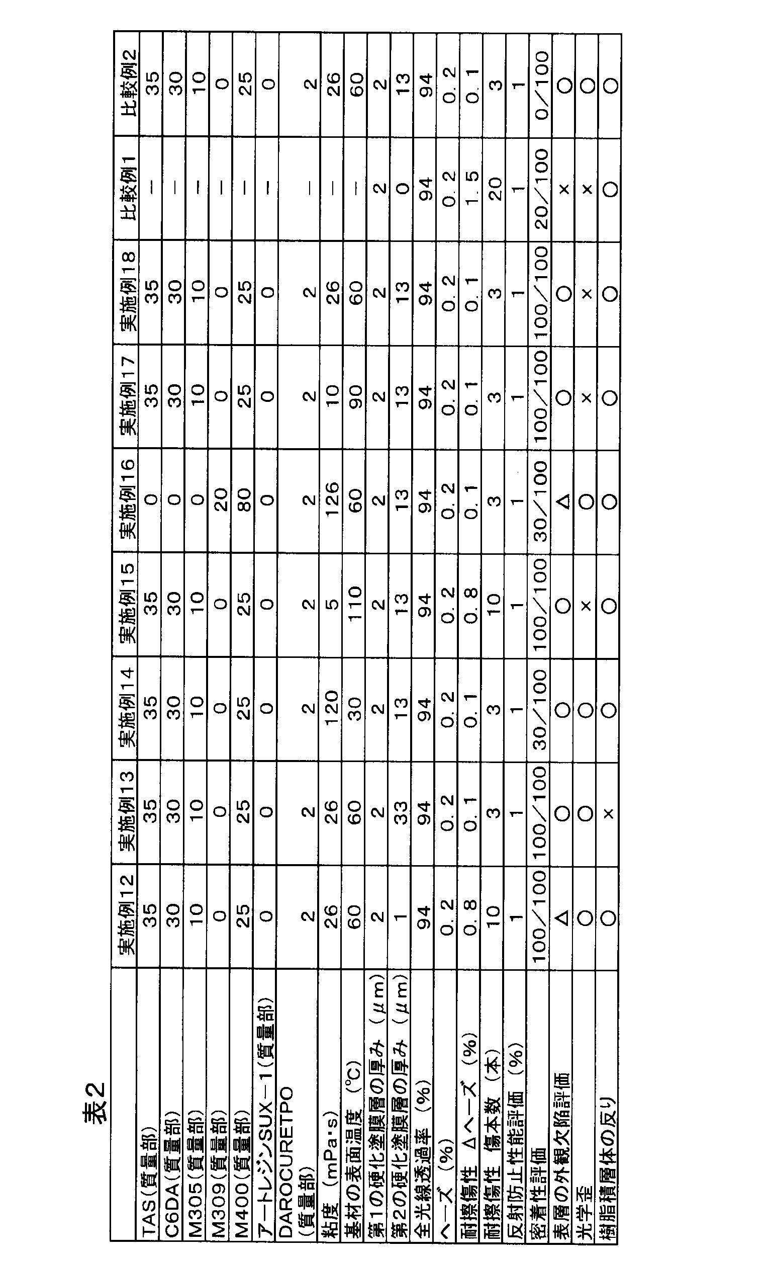
- Example 12 A resin laminate was produced in the same manner as in Example 1 except that the film thickness of the second cured coating film layer was changed as shown in Table 1 in Example 1. Since the film thickness of the second cured coating film layer was less than 3 ⁇ m, the hardness was lower than that of Example 1. Further, unlike Example 1, a surface layer foreign matter defect occurred. The results are shown in Table 2.
- Example 13 A resin laminate was produced in the same manner as in Example 1 except that the film thickness of the second cured coating film layer was changed as shown in Table 1 in Example 1. Unlike Example 1, warpage occurred because the film thickness of the second cured coating film layer was 30 ⁇ m or more. The results are shown in Table 2.
- Example 14 In Example 1, a resin laminate was produced in the same manner as in Example 1 except that the surface temperature of the substrate was changed as shown in Table 1. Since the substrate surface temperature was less than 40 ° C., the adhesion was lower than in Example 1. The results are shown in Table 2.
- Example 15 In Example 1, a resin laminate was produced in the same manner as in Example 1 except that the surface temperature of the substrate was changed as shown in Table 1. Since the substrate surface temperature was 100 ° C. or higher, the substrate was excessively dissolved as compared with Example 1, and the hardness was low. Moreover, since the viscosity of the ultraviolet curable mixture was 15 mPa ⁇ s or less, optical distortion occurred unlike Example 1. The results are shown in Table 2.
- Example 16 A resin laminate was produced in the same manner as in Example 1 except that the ultraviolet curable mixture composition was changed as shown in Table 1 in Example 1. Since the viscosity of the ultraviolet curable mixture was 120 mPa ⁇ s or more, the adhesion was lower than that of Example 1. Further, unlike Example 1, a surface layer foreign matter defect occurred. The results are shown in Table 2.
- Example 17 In Example 1, a resin laminate was produced in the same manner as in Example 1 except that the temperature was increased and the viscosity of the ultraviolet curable mixture was changed as shown in Table 2. Unlike Example 1, optical distortion occurred because the viscosity of the ultraviolet curable mixture was 15 mPa ⁇ s or less.
- Example 18 In Example 1, resin was applied in the same manner as in Example 1 except that the film was applied in parallel and linearly with respect to the film traveling direction, and a planar coating layer was formed using a No. 50 bar coder. A laminate was produced. When a planar coating layer was formed using a bar coder, a portion that was not partially coated was formed. Therefore, unlike in Example 1, streaky optical distortion was generated in the resin laminate. The results are shown in Table 2.
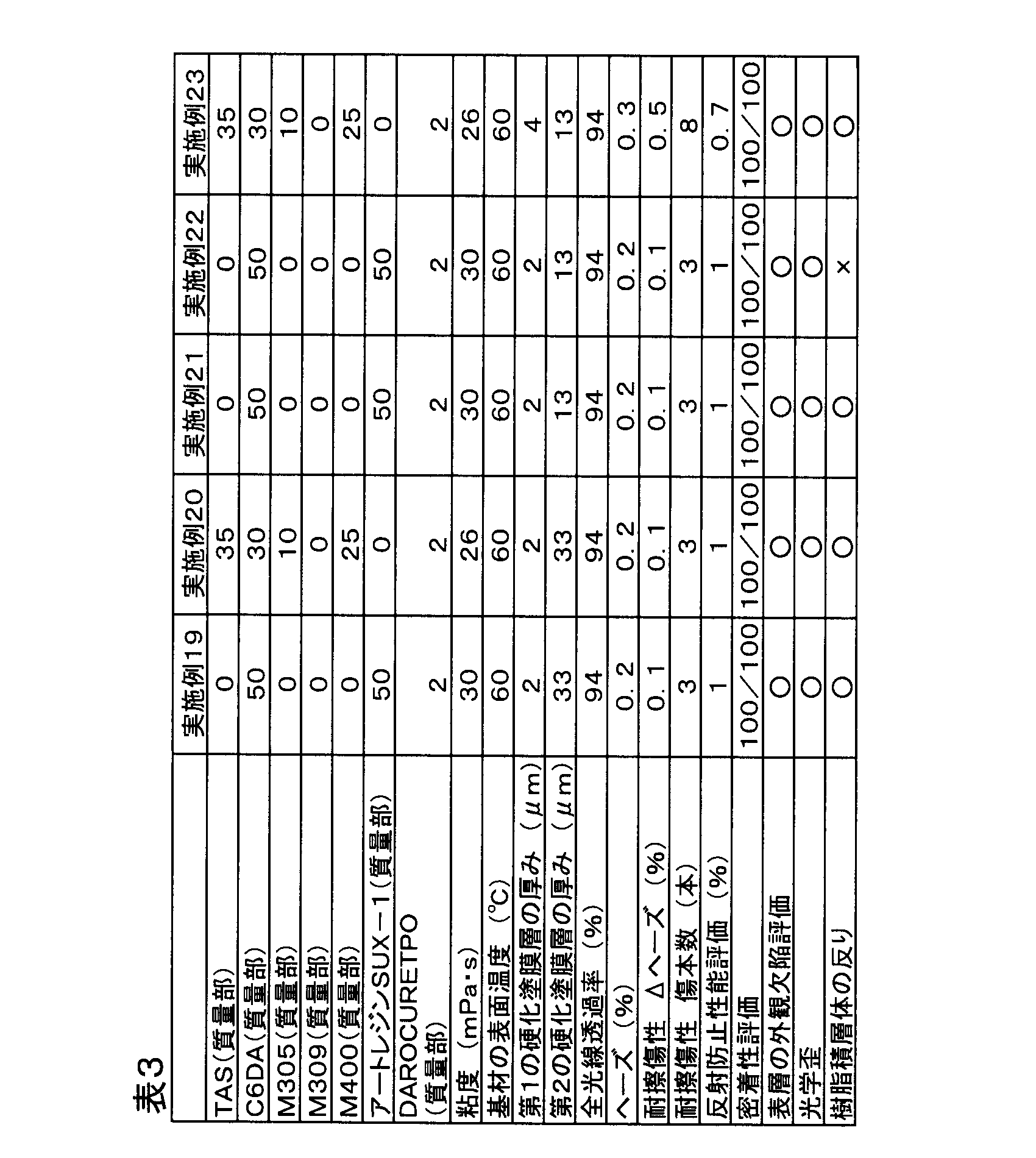
- Example 19 In Example 1, a resin laminate was produced in the same manner as in Example 1 except that the film thickness and composition of the second cured coating layer were changed as shown in Table 3. The film thickness of the second cured coating layer was 30 ⁇ m or more, but no warpage occurred because the urethane macromonomer (Art Resin SUX-1) was used. The results are shown in Table 3.
- Example 20 a resin laminate was produced in the same manner as in Example 13 except that the antireflection transfer film was rolled up around a paper tube with the following contents.
- ⁇ Paper tube 6 inches in diameter
- ⁇ PET base material thickness 100 ⁇ m
- Winding length 500m
- -Direction of winding of transfer layer Rolled up so that transfer layer is located on the inner side. Even when the thickness of the second cured coating film layer was 30 ⁇ m or more, no warpage occurred in the resin laminate. The results are shown in Table 3.
- Example 21 In Example 20, using acrylite MR100 as the resin base material, transfer to the surface where the hard coat layer was not formed via the second cured coating film layer having the film thickness and composition as shown in Table 3 A resin laminate was produced in the same manner as in Example 20 except that the layer was transferred. It was possible to cancel the warpage of the acrylite MR100 itself, that is, the warp that the antireflection layer forming surface side was inside the arc. The results are shown in Table 31.
- Example 22 In Example 21, a resin laminate was produced in the same manner as in Example 21 except that the winding direction of the transfer layer was changed to the outside of the roll. Unlike Example 21, there was no effect of suppressing warping, and warping of the laminate occurred. The results are shown in Table 3.
- Example 23 A resin laminate was prepared in the same manner as in Example 1 except that the antireflection transfer film in Example 1 was changed to the following single-layer antireflection film having only a low refractive index layer.
- MIBK methyl isobutyl ketone
- the low refractive index coating material was applied to a 100 ⁇ m PET film with a melamine release layer (product name AC-J, manufactured by Reiko Co., Ltd.) using a No. 4 bar coater and dried at 80 ° C. for 5 minutes. Thereafter, a low refractive index layer was formed by passing a position 20 cm below the 9.6 kW high-pressure mercury lamp at a speed of 2.5 m / min. Its refractive index was 1.38.
- the high refractive index paint was applied onto the low refractive index layer using a No. 4 bar coater and dried at 80 ° C. for 5 minutes. Thereafter, a high refractive index hard coat layer was formed by passing a position 20 cm below the 9.6 kW high-pressure mercury lamp at a speed of 2.5 m / min. Its refractive index was 1.60.
- an adhesive layer forming paint was applied onto the high refractive index layer using a No. 4 bar coater and dried at 80 ° C. for 5 minutes to form an adhesive layer.
- the film thickness of the low refractive index layer was 100 nm
- the film thickness of the high refractive index hard coat layer was 4 ⁇ m
- the film thickness of the adhesive layer was 200 nm.
- Table 3 Since it was a single-layer antireflection laminate, the reflection color was thinner than the laminates of the other examples.
- the adhesive layer side of the antireflection transfer film (Oike Kogyo Co., Ltd., trade name: STEP PAR-1) was the methacrylic resin substrate (Mitsubishi Rayon Co., Ltd., trade name: Acrylite EX001) side, and was laminated After that, it was pressed using a hydraulic molding machine (manufactured by Shoji Steel Co., Ltd.), and a pressure of 10 MPa was applied, and the upper and lower set temperatures were 120 ° C., and the pressure was applied for 10 minutes. When a thermocouple was attached to the film surface and the film surface temperature was measured, the surface temperature after 10 minutes was 100 ° C.
- Example 2 In Example 1, except that an antireflection transfer film having no adhesive layer (made by Oike Kogyo Co., Ltd., trade name: STEP PAR-1 was immersed in acetone for 10 minutes and the adhesive layer was removed) was used. In the same manner as in Example 1, a resin laminate was produced. Since it did not have an adhesive layer, the adhesion was insufficient. The results are shown in Table 2.
- the resin laminate of the present invention is a front panel of various displays such as a CRT, a liquid crystal display, an organic EL display, a plasma display, and a projection TV, and in front of an information display unit of an information terminal such as a mobile phone, a portable music player, and a mobile personal computer. It can be suitably used for a face plate or the like.
Landscapes
- Laminated Bodies (AREA)
- Surface Treatment Of Optical Elements (AREA)
- Application Of Or Painting With Fluid Materials (AREA)
Abstract
Description
ジエチレングリコールジ(メタ)アクリレート、トリエチレングリコールジ(メタ)アクリレート、テトラエチレングリコールジ(メタ)アクリレート等のポリエチレングリコールのジ(メタ)アクリレート;1,4-ブタンジオールジ(メタ)アクリレート、1,6-ヘキサンジオールジ(メタ)アクリレート、1,9-ノナンジオールジ(メタ)アクリレート等のアルキルジオールのジ(メタ)アクリレート;トリメチロールプロパントリ(メタ)アクリレート、トリメチロールエタントリ(メタ)アクリレート、ペンタグリセロールトリ(メタ)アクリレート、ペンタエリスリトールトリ(メタ)アクリレート、ペンタエリスリトールテトラ(メタ)アクリレート、グリセリントリ(メタ)アクリレート、ジペンタエリスリトールトリ(メタ)アクリレート、ジペンタエリスリトールテトラ(メタ)アクリレート、ジペンタエリスリトールペンタ(メタ)アクリレート、ジペンタエリスリトールヘキサ(メタ)アクリレート、トリペンタエリスリトールテトラ(メタ)アクリレート、トリペンタエリスリトールペンタ(メタ)アクリレート、トリペンタエリスリトールヘキサ(メタ)アクリレート、トリペンタエリスリトールヘプタ(メタ)アクリレート等の3官能以上のポリオールのポリ(メタ)アクリレート;などが挙げられる。
M(OR)m
(化学式中、Mは金属を表し、Rは炭素数1~5の炭化水素基を表し、mは金属Mの原子価(3または4)を表す。)
で示されるものであることが好ましい。金属Mとしては、チタン、アルミニウム、ジルコニウム、スズ等、特にチタンが適している。金属アルコキシドの具体例としては、チタンメトキサイド、チタンエトキサイド、チタンn-プロポキサイド、チタンイソプロポキサイド、チタンn-ブトキサイド、チタンイソブトキサイド、アルミニウムエトキサイド、アルミニウムイソプロポキシド、アルミニウムブトキシド、アルミニウムt-ブトキサイド、スズt-ブトキサイド、ジルコニウムエトキサイド、ジルコニウムn-プロポキサイド、ジルコニウムイソプロポキサイド、ジルコニウムn-ブトキサイド等が挙げられる。
「C6DA」:1,6-ヘキサンジオールジアクリレート(大阪有機化学工業(株)製)
「M305」:ペンタエリスリトールトリアクリレート M-305(東亞合成(株)製)
「M309」:トリメチロールプロパントリアクリレート M-309(東亞合成(株)製)
「M400」:ジペンタエリスリトールヘキサアクリレート M-400(東亞合成(株)製)
「アートレジンSUX-1」:ウレタン系マクロモノマー(根上産業(株)製)
「オプツールAR」:フッ素系低屈折率アクリレート、固形分濃度15重量%、メチルイソブチルケトン溶液(ダイキン化成品販売(株)製)
「オグソールEA-F5010」:フルオレン骨格含有アクリレート(大阪ガス化学(株)製)
「ダイヤナールBR-80」:アクリル樹脂(三菱レイヨン(株)製)。
「イルガキュア184」:1-ヒドロキシ-シクロヘキシル-フェニルケトン(チバジャパン(株)製)
「アクリライトEX001」:アクリル樹脂板(三菱レイヨン(株)製)。
各温度におけるB型粘度計の回転数6rpmの粘度を測定した。なお、粘度は基材の温度と同じ温度で測定した。
基材を加温予備加熱し、非接触型表面温度計(CHINO(株)製 ハンディ形放射温度計IR-TA)で測定した。
日本電色製HAZE METER NDH2000(商品名)を用いてJIS K7361-1に示される測定法に準拠して、全光線透過率を測定し、JIS K7136に示される測定法に準拠してヘーズを測定した。
擦傷試験の前後におけるヘーズの変化(Δヘーズ)をもって評価した。即ち、#000のスチールウールを装着した直径25.4mmの円形パッドを積層体の硬化塗膜層表面上に置き、500gの荷重下で、20mmの距離を10回往復擦傷し、擦傷前と擦傷後のヘーズ値の差を下式(1)より求めた。
[Δヘーズ(%)]=[擦傷後ヘーズ値(%)]-[擦傷前ヘーズ値(%)]・・(1)
また、試験後のサンプルの傷の本数を数えた。
シートの裏面をサンドペーパーで粗面化した後艶消し黒色スプレーで塗り、これをサンプルとし、分光光度計(日立製作所社製、「U-4000」)を用いて、入射角5°、波長380~780nmの範囲でJIS R3106に示される測定法に準拠してサンプルの表面の反射率を測定した。
クロスカット試験(JIS K5600-5-6)により評価した。試験を4回繰り返し、各25箇所の内、剥離せず残った箇所の数の4回分の合計を表示した。
目視にてサンプル表面の気泡、異物の有無を確認した。
○:気泡の咬み込み、異物無し
△:気泡の咬み込みは無いが、異物有り
×:気泡の咬み込み、異物有り
目視にてサンプルの歪の有無を確認した。
○:歪無し
×:歪あり。
80℃の環境で15時間放置した後の、30cm×30cmの樹脂積層体の反り量を測定した。なお、反り量は、平板の上にサンプルをおき、平板から反ったサンプルまでの距離を測定した。
○:反り量5mm以下
×:反り量5mm以上
反射防止層、硬化塗膜層について、(メトリコン社製、膜厚・屈折率測定装置、モデル2010、プリズムカプラ)を用いて594nmレーザーにおける屈折率及び膜厚を測定した。
屈折率を測定しないサンプルの膜厚測定は、ミクロトームにて厚み100nmにサンプルを切り出し透過型電子顕微鏡で観察して行った。透過型電子顕微鏡は日本電子製(JEOL)JEM-1010を用いて測定した。
反射防止転写フィルム(尾池工業(株)製、商品名:STEP PAR-1;フィルム(PETフィルム)、剥離層、反射防止層、硬化塗膜層、接着層の順に積層)の接着層側へTAS 35質量部、C6DA 30質量部、M305 10質量部、M400 25質量部、DAROCUR TPO 2質量部からなる紫外線硬化性混合物からなる塗料を、フィルムの進行方向に対して垂直に、かつ線状に塗布し、バーコーター(50号)を用いて面状の塗布層を形成した。なお、反射防止転写フィルムは、ロール状に巻き取られたものをそのまま使用したのではなく、ロール状に巻き取られたものから一部を切り出し、平面状にして保管されていたものを使用した。
実施例1において、第2の硬化塗膜層の膜厚を表1に示すように変更したこと以外は実施例1と同様にして、樹脂積層体を作製した。結果を表1に示す。
実施例1において、第2の硬化塗膜層の膜厚を表1に示すように変更したこと以外は実施例1と同様にして、樹脂積層体を作製した。結果を表1に示す。
実施例1において、樹脂基材の温度を表1に示すように変更したこと以外は実施例1と同様にして、樹脂積層体を作製した。結果を表1に示す。
実施例1において、紫外線硬化性混合物を表1に示すように変更したこと以外は実施例1と同様にして、樹脂積層体を作製した。結果を表1に示す。
実施例1において、紫外線硬化性混合物を表1に示すように変更したこと以外は実施例1と同様にして、樹脂積層体を作製した。結果を表1に示す。
実施例1において、紫外線硬化性混合物を表1に示すように変更したこと以外は実施例1と同様にして、樹脂積層体を作製した。結果を表1に示す。
実施例7において、樹脂基材の温度を表1に示すように変更したこと以外は実施例7と同様にして、樹脂積層体を作製した。結果を表1に示す。
実施例1において、紫外線硬化性混合物を表1に示すように変更したこと以外は実施例1と同様にして、樹脂積層体を作製した。結果を表1に示す。
実施例1において、反射防止転写フィルムを(尾池工業(株)製、商品名:STEP PAR-2;フィルム(PETフィルム)、剥離層、反射防止層、硬化塗膜層、接着層の順に積層)に変更したこと以外は実施例1と同様にして、樹脂積層体を作製した。結果を表1に示す。
実施例1において、樹脂基材を2mm厚のポリカーボネート樹脂(帝人化成(株)製、商品名:パンライトAD-5503)に変更したこと以外は実施例1と同様にして、樹脂積層体を作製した。結果を表1に示す。
実施例1において、第2の硬化塗膜層の膜厚を表1に示すように変更したこと以外は実施例1と同様にして、樹脂積層体を作製した。第2の硬化塗膜層の膜厚が、3μm未満であったため実施例1と比べて硬度が低かった。また実施例1と異なり表層の異物欠陥が発生した。結果を表2に示す。
実施例1において、第2の硬化塗膜層の膜厚を表1に示すように変更したこと以外は実施例1と同様にして、樹脂積層体を作製した。第2の硬化塗膜層の膜厚が、30μm以上であったため実施例1と異なり反りが発生した。結果を表2に示す。
実施例1において、基材の表面温度を表1に示すように変更したこと以外は実施例1と同様にして、樹脂積層体を作製した。基材表面温度が40℃未満であったため、実施例1と比べて密着性が低かった。結果を表2に示す。
実施例1において、基材の表面温度を表1に示すように変更したこと以外は実施例1と同様にして、樹脂積層体を作製した。基材表面温度が100℃以上であったため、実施例1と比べて過度な基材の溶解が起こり硬度が低かった。また、紫外線硬化性混合物の粘度が15mPa・s以下であったため、実施例1と異なり光学歪が発生した。結果を表2に示す。
実施例1において、紫外線硬化性混合物組成を表1に示すように変更したこと以外は実施例1と同様にして、樹脂積層体を作製した。紫外線硬化性混合物の粘度が120mPa・s以上であったため、実施例1と比べて密着性が低かった。また実施例1と異なり表層の異物欠陥が発生した。結果を表2に示す。
実施例1において、温度を加温し紫外線硬化性混合物の粘度を表2に示すように変更したこと以外は実施例1と同様にして、樹脂積層体を作製した。紫外線硬化性混合物の粘度が15mPa・s以下であったため、実施例1と異なり光学歪が発生した。
実施例1において、フィルムの進行方向に対して平行に、かつ線状に塗布し、50号のバーコーダーを用いて面状の塗布層を形成したこと以外は実施例1と同様にして、樹脂積層体を作製した。バーコーダーを用いて面状の塗布層を形成する際、部分的に塗布されてない箇所が形成された。従って該樹脂積層体には、実施例1と異なり筋状の光学歪が発生した。結果を表2に示す。
実施例1において、第2の硬化塗膜層の膜厚、組成を表3に示すように変更したこと以外は実施例1と同様にして、樹脂積層体を作製した。第2の硬化塗膜層の膜厚が、30μm以上であったが、ウレタンマクロモノマー(アートレジンSUX-1)を使用しているため、反りが発生しなかった。結果を表3に示す。
実施例13において、反射防止転写フィルムを以下の内容で紙管にロール状に巻き取られていたものを使用したこと以外は、実施例13と同様にして樹脂積層体を作製した。
・紙管:直径6インチ
・PET基材厚み:100μm
・巻き長:500m
・転写層の巻きの向き:転写層が内側に位置するように巻き取ったもの
第2の硬化塗膜層の厚みが30μm以上でも樹脂積層体に反りが発生しなかった。結果を表3に示す。
実施例20において、樹脂基材としてアクリライトMR100を用いて、そのハードコート層が形成されていない面へ、表3に示すような膜厚、組成の第2の硬化塗膜層を介して転写層を転写したこと以外は、実施例20と同様にして樹脂積層体を作製した。アクリライトMR100自身の反り、即ち、反射防止層形成面側が円弧の内側となるような反りを打ち消すことができた。結果を表31に示す。
実施例21において、転写層の巻きの向きをロールの外側としたこと以外は実施例21と同様にして、樹脂積層体を作製した。実施例21と異なり反りの抑制効果がなく、積層体の反りが発生した。結果を表3に示す。
実施例1における反射防止転写フィルムが低屈折率層のみを有する以下の単層反射防止フィルムに変更したこと以外は実施例1と同様に樹脂積層体を作製した。
オプツールAR(固形分濃度15質量%)へMIBK(メチルイソブチルケトン)を添加し、固形分濃度1質量%へ希釈し、オプツールARの固形分100質量部に対して、イルガキュア184を5質量部添加し、低屈折率塗料を調製した。
オグソールEA-F5010へMIBK(メチルイソブチルケトン)を添加し、固形分濃度50質量%へ希釈し、オグソールEA-F5010の固形分100質量部に対して、イルガキュア184を5質量部添加し、高屈折率塗料を調製した。
ダイヤナールBR-80 50質量部とジルコニアゾル(住友大阪セメント(株)製 固形分濃度(ジルコニア)30質量%メチルエチルケトン分散ゾル)166質量部とを混合し、さらにMIBK(メチルイソブチルケトン)を添加し固形分濃度(ダイヤナールBR-80とジルコニアとの固形分合計100質量部に対して)が2質量%となるように調製した。
100μmのメラミン剥離層付きPETフィルム(レイコウ(株)社製、品名AC-J)へ、4号バーコーターを用いて、前記低屈折率塗料を塗布し80℃5分で乾燥させた。その後、9.6kWの高圧水銀ランプの下20cmの位置を2.5m/minのスピードで通過させて低屈折率層を形成した。その屈折率は1.38であった。
反射防止転写フィルム(尾池工業(株)製、商品名:STEP PAR-1)の接着層側をメタクリル樹脂基材(三菱レイヨン(株)製、商品名:アクリライトEX001)側とし、張り合わせた後、油圧成形機(庄司鉄鋼(株)製)を用いてプレスし、10MPaの圧力をかけ上部、下部の設定温度を120℃として10分間圧力をかけた。フィルム表面に熱伝対を取り付け、フィルム表面温度を測定したところ、10分後の表面温度は、100℃であった。その後、圧力をかけた状態で30℃まで冷却を行った後、フィルムを剥離した。得られた樹脂積層体には第2の硬化塗膜層が存在しなかったため、硬度が不足していた。また表層の異物欠陥が発生した。さらに、第1の硬化塗膜層と樹脂基材の密着性は十分ではなかった。結果を表2に示す。
実施例1において、接着層を有さない反射防止転写フィルム(尾池工業(株)製、商品名:STEP PAR-1をアセトンへ10分間浸漬し、接着層を除去)を用いたこと以外は、実施例1と同様にして、樹脂積層体を作製した。接着層を有していなかったため、密着性が不十分であった。結果を表2に示す。

Claims (5)
- 透明フィルムの片面に、剥離層、反射防止層、第1の硬化塗膜層、及び接着層が順次形成された転写フィルムの該接着層の上に、無溶剤型活性エネルギー線硬化性混合物を塗布し塗布層を形成する第1の工程、前記塗布層側を樹脂基材に貼り付ける第2の工程、前記塗布層中の活性エネルギー線硬化性混合物を硬化させて第2の硬化塗膜層とする第3の工程、及び前記樹脂基材上に積層された第2の硬化塗膜層、接着層、第1の硬化塗膜層、及び反射防止層を残して前記透明フィルムを剥がす第4の工程、を含む樹脂積層体の製造方法。
- 第1の硬化塗膜層の膜厚が0.5μm~10μmであり、第2の硬化塗膜層の膜厚が0.5μm~40μmである請求項1に記載の樹脂積層体の製造方法。
- 第2の工程において樹脂基材の表面温度を40℃~100℃とし、前記表面温度と同温度における第2の硬化塗膜層を形成する活性エネルギー線硬化性混合物の粘度が15~120mPa・sである請求項1に記載の樹脂積層体の製造方法。
- 反射防止層が2層以上の構造である請求項1に記載の樹脂積層体の製造方法。
- 反射防止層が単層の構造であり、第1の硬化塗膜層の屈折率が反射防止層の屈折率より高い請求項1に記載の樹脂積層体の製造方法。
Priority Applications (1)
| Application Number | Priority Date | Filing Date | Title |
|---|---|---|---|
| CN200980140981.7A CN102186670B (zh) | 2008-08-29 | 2009-08-26 | 树脂层叠体的制造方法 |
Applications Claiming Priority (4)
| Application Number | Priority Date | Filing Date | Title |
|---|---|---|---|
| JP2008221993 | 2008-08-29 | ||
| JP2008-221993 | 2008-08-29 | ||
| JP2009-090894 | 2009-04-03 | ||
| JP2009090894A JP2010076423A (ja) | 2008-08-29 | 2009-04-03 | 樹脂積層体及び樹脂積層体の製造方法 |
Publications (1)
| Publication Number | Publication Date |
|---|---|
| WO2010024274A1 true WO2010024274A1 (ja) | 2010-03-04 |
Family
ID=41721441
Family Applications (1)
| Application Number | Title | Priority Date | Filing Date |
|---|---|---|---|
| PCT/JP2009/064832 Ceased WO2010024274A1 (ja) | 2008-08-29 | 2009-08-26 | 樹脂積層体の製造方法 |
Country Status (5)
| Country | Link |
|---|---|
| JP (1) | JP2010076423A (ja) |
| KR (1) | KR101578254B1 (ja) |
| CN (1) | CN102186670B (ja) |
| TW (1) | TWI404629B (ja) |
| WO (1) | WO2010024274A1 (ja) |
Cited By (4)
| Publication number | Priority date | Publication date | Assignee | Title |
|---|---|---|---|---|
| CN103153610A (zh) * | 2010-09-29 | 2013-06-12 | 日东电工株式会社 | 带粘合剂层的树脂薄膜、层叠薄膜和触摸面板 |
| EP2657729A4 (en) * | 2010-12-22 | 2014-07-30 | Mitsubishi Rayon Co | TRANSFER FILM, MANUFACTURING METHOD, LAMINATE AND MANUFACTURING METHOD THEREFOR |
| JP2015230477A (ja) * | 2014-06-06 | 2015-12-21 | コニカミノルタ株式会社 | 光学反射フィルム |
| US9950559B2 (en) | 2012-09-28 | 2018-04-24 | Valspar Sourcing, Inc. | Multilayered laminate and process for preparing the same |
Families Citing this family (9)
| Publication number | Priority date | Publication date | Assignee | Title |
|---|---|---|---|---|
| JP2012151170A (ja) * | 2011-01-17 | 2012-08-09 | Ma Packaging:Kk | 太陽電池モジュール用バックシート素材の製造方法 |
| TWI499808B (zh) * | 2011-06-01 | 2015-09-11 | Au Optronics Corp | 光學複合基材 |
| JP5478600B2 (ja) * | 2011-12-14 | 2014-04-23 | 尾池工業株式会社 | 機能性膜の形成方法、およびガスバリア膜の形成方法 |
| JP6016009B2 (ja) * | 2012-05-08 | 2016-10-26 | 三菱レイヨン株式会社 | 転写フィルム、積層体及びそれらの製造方法 |
| JP6429011B2 (ja) * | 2014-11-13 | 2018-11-28 | パナソニックIpマネジメント株式会社 | インモールド成型用転写フィルム及びその製造方法 |
| WO2020075565A1 (ja) * | 2018-10-12 | 2020-04-16 | 大日本印刷株式会社 | 透明性樹脂フィルム、化粧板及び化粧板の製造方法 |
| KR20220020270A (ko) * | 2019-06-17 | 2022-02-18 | 주식회사 쿠라레 | 금속 피복 적층체의 제조 방법 |
| WO2021107000A1 (ja) * | 2019-11-29 | 2021-06-03 | 大日本印刷株式会社 | 積層体、積層体の製造方法、積層用フィルム、画像表示装置 |
| CN113263850B (zh) * | 2021-05-13 | 2022-11-01 | 刘晨 | 一种改善水洗褪色现象的乳胶墨水数码打印膜材及其制备方法 |
Citations (6)
| Publication number | Priority date | Publication date | Assignee | Title |
|---|---|---|---|---|
| JPH11271506A (ja) * | 1998-03-20 | 1999-10-08 | Kimoto & Co Ltd | 反射防止膜転写材及び反射防止膜転写方法 |
| JP2000009908A (ja) * | 1998-06-18 | 2000-01-14 | Fuji Photo Film Co Ltd | 反射防止膜および画像表示装置 |
| JP2003215308A (ja) * | 2002-01-25 | 2003-07-30 | Tdk Corp | 転写用反射防止フィルム、その製造方法及び反射防止処理された物体 |
| JP2006212987A (ja) * | 2005-02-04 | 2006-08-17 | Kuraray Co Ltd | 転写材 |
| JP2007038543A (ja) * | 2005-08-03 | 2007-02-15 | Mitsubishi Plastics Ind Ltd | 樹脂積層体 |
| JP2007038542A (ja) * | 2005-08-03 | 2007-02-15 | Mitsubishi Plastics Ind Ltd | 樹脂積層体 |
Family Cites Families (9)
| Publication number | Priority date | Publication date | Assignee | Title |
|---|---|---|---|---|
| JP3369684B2 (ja) | 1993-11-26 | 2003-01-20 | 大日本印刷株式会社 | 反射防止フィルム及びその製造方法 |
| JP3932060B2 (ja) * | 1995-09-14 | 2007-06-20 | 大日本印刷株式会社 | 反射防止シート |
| WO2000020228A1 (en) * | 1998-10-01 | 2000-04-13 | Nissha Printing Co., Ltd. | Transfer material, surface-protective sheet, and process for producing molded article with these |
| JP4077596B2 (ja) | 2000-05-31 | 2008-04-16 | 中島工業株式会社 | 低反射層を有する転写材及びこれを用いた成型品の製造方法 |
| US6844116B2 (en) * | 2000-06-01 | 2005-01-18 | Nippon Paper Industries Co., Ltd | Transfer sheet for transferring protective layer for photographic emulsion face and photomask with protective layer |
| JP2004170545A (ja) * | 2002-11-18 | 2004-06-17 | Nippon Petrochemicals Co Ltd | 光学素子の製造方法 |
| ATE500598T1 (de) * | 2003-11-28 | 2011-03-15 | Teijin Ltd | Transparentes leitfähiges laminat und transparente berührungstafel damit |
| JP4395742B2 (ja) | 2004-08-04 | 2010-01-13 | 株式会社クラレ | 転写材、その製造方法及び転写物 |
| US11327621B2 (en) * | 2007-01-16 | 2022-05-10 | Teijin Limited | Transparent conductive multilayer body and touch panel made of the same |
-
2009
- 2009-04-03 JP JP2009090894A patent/JP2010076423A/ja active Pending
- 2009-08-26 WO PCT/JP2009/064832 patent/WO2010024274A1/ja not_active Ceased
- 2009-08-26 KR KR1020117007118A patent/KR101578254B1/ko not_active Expired - Fee Related
- 2009-08-26 CN CN200980140981.7A patent/CN102186670B/zh not_active Expired - Fee Related
- 2009-08-27 TW TW098128893A patent/TWI404629B/zh not_active IP Right Cessation
Patent Citations (6)
| Publication number | Priority date | Publication date | Assignee | Title |
|---|---|---|---|---|
| JPH11271506A (ja) * | 1998-03-20 | 1999-10-08 | Kimoto & Co Ltd | 反射防止膜転写材及び反射防止膜転写方法 |
| JP2000009908A (ja) * | 1998-06-18 | 2000-01-14 | Fuji Photo Film Co Ltd | 反射防止膜および画像表示装置 |
| JP2003215308A (ja) * | 2002-01-25 | 2003-07-30 | Tdk Corp | 転写用反射防止フィルム、その製造方法及び反射防止処理された物体 |
| JP2006212987A (ja) * | 2005-02-04 | 2006-08-17 | Kuraray Co Ltd | 転写材 |
| JP2007038543A (ja) * | 2005-08-03 | 2007-02-15 | Mitsubishi Plastics Ind Ltd | 樹脂積層体 |
| JP2007038542A (ja) * | 2005-08-03 | 2007-02-15 | Mitsubishi Plastics Ind Ltd | 樹脂積層体 |
Cited By (4)
| Publication number | Priority date | Publication date | Assignee | Title |
|---|---|---|---|---|
| CN103153610A (zh) * | 2010-09-29 | 2013-06-12 | 日东电工株式会社 | 带粘合剂层的树脂薄膜、层叠薄膜和触摸面板 |
| EP2657729A4 (en) * | 2010-12-22 | 2014-07-30 | Mitsubishi Rayon Co | TRANSFER FILM, MANUFACTURING METHOD, LAMINATE AND MANUFACTURING METHOD THEREFOR |
| US9950559B2 (en) | 2012-09-28 | 2018-04-24 | Valspar Sourcing, Inc. | Multilayered laminate and process for preparing the same |
| JP2015230477A (ja) * | 2014-06-06 | 2015-12-21 | コニカミノルタ株式会社 | 光学反射フィルム |
Also Published As
| Publication number | Publication date |
|---|---|
| KR101578254B1 (ko) | 2015-12-16 |
| CN102186670B (zh) | 2014-02-12 |
| KR20110063495A (ko) | 2011-06-10 |
| TW201012646A (en) | 2010-04-01 |
| JP2010076423A (ja) | 2010-04-08 |
| CN102186670A (zh) | 2011-09-14 |
| TWI404629B (zh) | 2013-08-11 |
Similar Documents
| Publication | Publication Date | Title |
|---|---|---|
| WO2010024274A1 (ja) | 樹脂積層体の製造方法 | |
| JP5747439B2 (ja) | アクリル系樹脂シートを連続的に製造する方法 | |
| JP5728945B2 (ja) | 防汚組成物、防汚膜、防汚積層膜、転写フィルム及び樹脂積層体、並びに樹脂積層体の製造方法 | |
| JP4952910B2 (ja) | 活性エネルギー線硬化性樹脂組成物およびその用途 | |
| TWI527692B (zh) | 轉印薄膜及其製造方法以及積層體及其製造方法 | |
| JP2014519410A (ja) | コーティングされたポリマー支持体または積層体の連続インライン製造方法 | |
| TWI631879B (zh) | 含有金屬氧化物微粒子的膜、轉印薄膜及其製造方法以及積層體及其製造方法 | |
| WO2015093404A1 (ja) | 樹脂積層体及びその製造方法 | |
| JP5594509B2 (ja) | 積層体及び積層体の製造方法 | |
| JP5411690B2 (ja) | 樹脂積層体及び樹脂積層体の製造方法 | |
| JP6016009B2 (ja) | 転写フィルム、積層体及びそれらの製造方法 | |
| KR20140103610A (ko) | 반사방지 필름의 제조방법 | |
| JP5497342B2 (ja) | 積層樹脂板の製造方法及びディスプレー前面板 | |
| JP6035871B2 (ja) | 反射防止積層体、その製造方法、及び画像表示装置 | |
| JP5601496B2 (ja) | 被膜用シリカゾルの製造方法、被膜用組成物、被膜、被膜を表層に有する樹脂積層体、及びその製造方法 | |
| JP2021143215A (ja) | フィルム及び積層体 | |
| JP2009274394A (ja) | 保護板 | |
| JP2015090482A (ja) | 積層体及びその製造方法 |
Legal Events
| Date | Code | Title | Description |
|---|---|---|---|
| WWE | Wipo information: entry into national phase |
Ref document number: 200980140981.7 Country of ref document: CN |
|
| 121 | Ep: the epo has been informed by wipo that ep was designated in this application |
Ref document number: 09809925 Country of ref document: EP Kind code of ref document: A1 |
|
| NENP | Non-entry into the national phase |
Ref country code: DE |
|
| ENP | Entry into the national phase |
Ref document number: 20117007118 Country of ref document: KR Kind code of ref document: A |
|
| 122 | Ep: pct application non-entry in european phase |
Ref document number: 09809925 Country of ref document: EP Kind code of ref document: A1 |