WO2010004703A1 - 有機エレクトロルミネッセンスパネルの製造方法 - Google Patents
有機エレクトロルミネッセンスパネルの製造方法 Download PDFInfo
- Publication number
- WO2010004703A1 WO2010004703A1 PCT/JP2009/003030 JP2009003030W WO2010004703A1 WO 2010004703 A1 WO2010004703 A1 WO 2010004703A1 JP 2009003030 W JP2009003030 W JP 2009003030W WO 2010004703 A1 WO2010004703 A1 WO 2010004703A1
- Authority
- WO
- WIPO (PCT)
- Prior art keywords
- sensitive adhesive
- pressure
- organic
- glass substrate
- panel
- Prior art date
Links
Images

Classifications
-
- H—ELECTRICITY
- H10—SEMICONDUCTOR DEVICES; ELECTRIC SOLID-STATE DEVICES NOT OTHERWISE PROVIDED FOR
- H10K—ORGANIC ELECTRIC SOLID-STATE DEVICES
- H10K50/00—Organic light-emitting devices
-
- H—ELECTRICITY
- H10—SEMICONDUCTOR DEVICES; ELECTRIC SOLID-STATE DEVICES NOT OTHERWISE PROVIDED FOR
- H10K—ORGANIC ELECTRIC SOLID-STATE DEVICES
- H10K71/00—Manufacture or treatment specially adapted for the organic devices covered by this subclass
- H10K71/60—Forming conductive regions or layers, e.g. electrodes
-
- C—CHEMISTRY; METALLURGY
- C08—ORGANIC MACROMOLECULAR COMPOUNDS; THEIR PREPARATION OR CHEMICAL WORKING-UP; COMPOSITIONS BASED THEREON
- C08K—Use of inorganic or non-macromolecular organic substances as compounding ingredients
- C08K7/00—Use of ingredients characterised by shape
- C08K7/22—Expanded, porous or hollow particles
-
- C—CHEMISTRY; METALLURGY
- C09—DYES; PAINTS; POLISHES; NATURAL RESINS; ADHESIVES; COMPOSITIONS NOT OTHERWISE PROVIDED FOR; APPLICATIONS OF MATERIALS NOT OTHERWISE PROVIDED FOR
- C09J—ADHESIVES; NON-MECHANICAL ASPECTS OF ADHESIVE PROCESSES IN GENERAL; ADHESIVE PROCESSES NOT PROVIDED FOR ELSEWHERE; USE OF MATERIALS AS ADHESIVES
- C09J5/00—Adhesive processes in general; Adhesive processes not provided for elsewhere, e.g. relating to primers
- C09J5/06—Adhesive processes in general; Adhesive processes not provided for elsewhere, e.g. relating to primers involving heating of the applied adhesive
-
- C—CHEMISTRY; METALLURGY
- C09—DYES; PAINTS; POLISHES; NATURAL RESINS; ADHESIVES; COMPOSITIONS NOT OTHERWISE PROVIDED FOR; APPLICATIONS OF MATERIALS NOT OTHERWISE PROVIDED FOR
- C09J—ADHESIVES; NON-MECHANICAL ASPECTS OF ADHESIVE PROCESSES IN GENERAL; ADHESIVE PROCESSES NOT PROVIDED FOR ELSEWHERE; USE OF MATERIALS AS ADHESIVES
- C09J5/00—Adhesive processes in general; Adhesive processes not provided for elsewhere, e.g. relating to primers
- C09J5/08—Adhesive processes in general; Adhesive processes not provided for elsewhere, e.g. relating to primers using foamed adhesives
-
- C—CHEMISTRY; METALLURGY
- C09—DYES; PAINTS; POLISHES; NATURAL RESINS; ADHESIVES; COMPOSITIONS NOT OTHERWISE PROVIDED FOR; APPLICATIONS OF MATERIALS NOT OTHERWISE PROVIDED FOR
- C09J—ADHESIVES; NON-MECHANICAL ASPECTS OF ADHESIVE PROCESSES IN GENERAL; ADHESIVE PROCESSES NOT PROVIDED FOR ELSEWHERE; USE OF MATERIALS AS ADHESIVES
- C09J7/00—Adhesives in the form of films or foils
- C09J7/30—Adhesives in the form of films or foils characterised by the adhesive composition
- C09J7/38—Pressure-sensitive adhesives [PSA]
-
- H—ELECTRICITY
- H10—SEMICONDUCTOR DEVICES; ELECTRIC SOLID-STATE DEVICES NOT OTHERWISE PROVIDED FOR
- H10K—ORGANIC ELECTRIC SOLID-STATE DEVICES
- H10K71/00—Manufacture or treatment specially adapted for the organic devices covered by this subclass
-
- H—ELECTRICITY
- H10—SEMICONDUCTOR DEVICES; ELECTRIC SOLID-STATE DEVICES NOT OTHERWISE PROVIDED FOR
- H10K—ORGANIC ELECTRIC SOLID-STATE DEVICES
- H10K71/00—Manufacture or treatment specially adapted for the organic devices covered by this subclass
- H10K71/10—Deposition of organic active material
- H10K71/16—Deposition of organic active material using physical vapour deposition [PVD], e.g. vacuum deposition or sputtering
- H10K71/164—Deposition of organic active material using physical vapour deposition [PVD], e.g. vacuum deposition or sputtering using vacuum deposition
-
- H—ELECTRICITY
- H10—SEMICONDUCTOR DEVICES; ELECTRIC SOLID-STATE DEVICES NOT OTHERWISE PROVIDED FOR
- H10K—ORGANIC ELECTRIC SOLID-STATE DEVICES
- H10K71/00—Manufacture or treatment specially adapted for the organic devices covered by this subclass
- H10K71/80—Manufacture or treatment specially adapted for the organic devices covered by this subclass using temporary substrates
-
- H—ELECTRICITY
- H10—SEMICONDUCTOR DEVICES; ELECTRIC SOLID-STATE DEVICES NOT OTHERWISE PROVIDED FOR
- H10K—ORGANIC ELECTRIC SOLID-STATE DEVICES
- H10K77/00—Constructional details of devices covered by this subclass and not covered by groups H10K10/80, H10K30/80, H10K50/80 or H10K59/80
- H10K77/10—Substrates, e.g. flexible substrates
-
- C—CHEMISTRY; METALLURGY
- C09—DYES; PAINTS; POLISHES; NATURAL RESINS; ADHESIVES; COMPOSITIONS NOT OTHERWISE PROVIDED FOR; APPLICATIONS OF MATERIALS NOT OTHERWISE PROVIDED FOR
- C09J—ADHESIVES; NON-MECHANICAL ASPECTS OF ADHESIVE PROCESSES IN GENERAL; ADHESIVE PROCESSES NOT PROVIDED FOR ELSEWHERE; USE OF MATERIALS AS ADHESIVES
- C09J2301/00—Additional features of adhesives in the form of films or foils
- C09J2301/10—Additional features of adhesives in the form of films or foils characterized by the structural features of the adhesive tape or sheet
- C09J2301/12—Additional features of adhesives in the form of films or foils characterized by the structural features of the adhesive tape or sheet by the arrangement of layers
- C09J2301/124—Additional features of adhesives in the form of films or foils characterized by the structural features of the adhesive tape or sheet by the arrangement of layers the adhesive layer being present on both sides of the carrier, e.g. double-sided adhesive tape
-
- C—CHEMISTRY; METALLURGY
- C09—DYES; PAINTS; POLISHES; NATURAL RESINS; ADHESIVES; COMPOSITIONS NOT OTHERWISE PROVIDED FOR; APPLICATIONS OF MATERIALS NOT OTHERWISE PROVIDED FOR
- C09J—ADHESIVES; NON-MECHANICAL ASPECTS OF ADHESIVE PROCESSES IN GENERAL; ADHESIVE PROCESSES NOT PROVIDED FOR ELSEWHERE; USE OF MATERIALS AS ADHESIVES
- C09J2301/00—Additional features of adhesives in the form of films or foils
- C09J2301/40—Additional features of adhesives in the form of films or foils characterized by the presence of essential components
- C09J2301/408—Additional features of adhesives in the form of films or foils characterized by the presence of essential components additives as essential feature of the adhesive layer
-
- C—CHEMISTRY; METALLURGY
- C09—DYES; PAINTS; POLISHES; NATURAL RESINS; ADHESIVES; COMPOSITIONS NOT OTHERWISE PROVIDED FOR; APPLICATIONS OF MATERIALS NOT OTHERWISE PROVIDED FOR
- C09J—ADHESIVES; NON-MECHANICAL ASPECTS OF ADHESIVE PROCESSES IN GENERAL; ADHESIVE PROCESSES NOT PROVIDED FOR ELSEWHERE; USE OF MATERIALS AS ADHESIVES
- C09J2301/00—Additional features of adhesives in the form of films or foils
- C09J2301/40—Additional features of adhesives in the form of films or foils characterized by the presence of essential components
- C09J2301/412—Additional features of adhesives in the form of films or foils characterized by the presence of essential components presence of microspheres
-
- C—CHEMISTRY; METALLURGY
- C09—DYES; PAINTS; POLISHES; NATURAL RESINS; ADHESIVES; COMPOSITIONS NOT OTHERWISE PROVIDED FOR; APPLICATIONS OF MATERIALS NOT OTHERWISE PROVIDED FOR
- C09J—ADHESIVES; NON-MECHANICAL ASPECTS OF ADHESIVE PROCESSES IN GENERAL; ADHESIVE PROCESSES NOT PROVIDED FOR ELSEWHERE; USE OF MATERIALS AS ADHESIVES
- C09J2301/00—Additional features of adhesives in the form of films or foils
- C09J2301/50—Additional features of adhesives in the form of films or foils characterized by process specific features
- C09J2301/502—Additional features of adhesives in the form of films or foils characterized by process specific features process for debonding adherents
-
- H—ELECTRICITY
- H10—SEMICONDUCTOR DEVICES; ELECTRIC SOLID-STATE DEVICES NOT OTHERWISE PROVIDED FOR
- H10K—ORGANIC ELECTRIC SOLID-STATE DEVICES
- H10K59/00—Integrated devices, or assemblies of multiple devices, comprising at least one organic light-emitting element covered by group H10K50/00
- H10K59/10—OLED displays
- H10K59/12—Active-matrix OLED [AMOLED] displays
- H10K59/1201—Manufacture or treatment
-
- Y—GENERAL TAGGING OF NEW TECHNOLOGICAL DEVELOPMENTS; GENERAL TAGGING OF CROSS-SECTIONAL TECHNOLOGIES SPANNING OVER SEVERAL SECTIONS OF THE IPC; TECHNICAL SUBJECTS COVERED BY FORMER USPC CROSS-REFERENCE ART COLLECTIONS [XRACs] AND DIGESTS
- Y02—TECHNOLOGIES OR APPLICATIONS FOR MITIGATION OR ADAPTATION AGAINST CLIMATE CHANGE
- Y02E—REDUCTION OF GREENHOUSE GAS [GHG] EMISSIONS, RELATED TO ENERGY GENERATION, TRANSMISSION OR DISTRIBUTION
- Y02E10/00—Energy generation through renewable energy sources
- Y02E10/50—Photovoltaic [PV] energy
- Y02E10/549—Organic PV cells
-
- Y—GENERAL TAGGING OF NEW TECHNOLOGICAL DEVELOPMENTS; GENERAL TAGGING OF CROSS-SECTIONAL TECHNOLOGIES SPANNING OVER SEVERAL SECTIONS OF THE IPC; TECHNICAL SUBJECTS COVERED BY FORMER USPC CROSS-REFERENCE ART COLLECTIONS [XRACs] AND DIGESTS
- Y02—TECHNOLOGIES OR APPLICATIONS FOR MITIGATION OR ADAPTATION AGAINST CLIMATE CHANGE
- Y02P—CLIMATE CHANGE MITIGATION TECHNOLOGIES IN THE PRODUCTION OR PROCESSING OF GOODS
- Y02P70/00—Climate change mitigation technologies in the production process for final industrial or consumer products
- Y02P70/50—Manufacturing or production processes characterised by the final manufactured product
-
- Y—GENERAL TAGGING OF NEW TECHNOLOGICAL DEVELOPMENTS; GENERAL TAGGING OF CROSS-SECTIONAL TECHNOLOGIES SPANNING OVER SEVERAL SECTIONS OF THE IPC; TECHNICAL SUBJECTS COVERED BY FORMER USPC CROSS-REFERENCE ART COLLECTIONS [XRACs] AND DIGESTS
- Y10—TECHNICAL SUBJECTS COVERED BY FORMER USPC
- Y10T—TECHNICAL SUBJECTS COVERED BY FORMER US CLASSIFICATION
- Y10T156/00—Adhesive bonding and miscellaneous chemical manufacture
- Y10T156/11—Methods of delaminating, per se; i.e., separating at bonding face
- Y10T156/1153—Temperature change for delamination [e.g., heating during delaminating, etc.]
- Y10T156/1163—Sintering for delamination
-
- Y—GENERAL TAGGING OF NEW TECHNOLOGICAL DEVELOPMENTS; GENERAL TAGGING OF CROSS-SECTIONAL TECHNOLOGIES SPANNING OVER SEVERAL SECTIONS OF THE IPC; TECHNICAL SUBJECTS COVERED BY FORMER USPC CROSS-REFERENCE ART COLLECTIONS [XRACs] AND DIGESTS
- Y10—TECHNICAL SUBJECTS COVERED BY FORMER USPC
- Y10T—TECHNICAL SUBJECTS COVERED BY FORMER US CLASSIFICATION
- Y10T156/00—Adhesive bonding and miscellaneous chemical manufacture
- Y10T156/11—Methods of delaminating, per se; i.e., separating at bonding face
- Y10T156/1168—Gripping and pulling work apart during delaminating
- Y10T156/1195—Delaminating from release surface
Definitions
- the present invention relates to a method for producing an organic electroluminescence panel using a double-sided adhesive tape.
- the organic electroluminescence panel according to the present invention is very useful as a display device, a display, and various light sources.
- organic electroluminescence (hereinafter sometimes referred to as “organic EL”) element has a structure in which a light-emitting layer containing a light-emitting compound is sandwiched between a cathode and an anode, and electrons and holes are injected into the light-emitting layer. It is an element that emits light by utilizing light emission (fluorescence, phosphorescence) when excitons are generated by recombination to generate excitons, and at a voltage of several tens to several tens of volts.
- substrate can be used as a display device, a display, and various light emission sources.
- the jig set method has a problem that it is inferior in maintainability and workability because it is necessary to use a jig suitable for each processing process in consideration of liquid residue and processing unevenness at the time of WET processing (chemical solution processing).
- the ultrathin glass substrate may be damaged due to stress when peeling and removing the adhesive sheet that is no longer necessary after the manufacturing process.
- the pedestal system that is bonded to the support substrate via wax or adhesive, the process of removing the wax and adhesive adhering to the back of the ultrathin glass substrate using an organic solvent after the manufacturing process Therefore, it is difficult to improve productivity.
- Patent Document 2 discloses a pressure-sensitive adhesive sheet for temporarily fixing a fragile adherend, which can be easily peeled and recovered without damaging the fragile adherend by heat treatment.
- a heat-peelable pressure-sensitive adhesive sheet comprising a heat-expandable pressure-sensitive adhesive layer containing heat-expandable microspheres on at least one of the bases is described.
- the thermally expandable microspheres contain a hydrocarbon gas in a spherical rubber-like elastic body. When heated at a temperature equal to or higher than a certain temperature, the hydrocarbon gas expands and / or the rubber-like elastic body expands and / or It has the property of foaming.
- an organic EL panel manufacturing method that uses an ultrathin glass substrate and has excellent flexibility and gas barrier properties, the ultrathin glass substrate is protected from being “cracked” or “chipped” due to conveyance during the manufacturing process.
- an organic EL element is formed by vacuum deposition, the organic EL element can be formed efficiently by quickly reaching a predetermined degree of vacuum, and after the manufacturing process, an ultrathin glass substrate is formed.
- An organic EL panel manufacturing method has been found that can recover the obtained organic EL panel without being damaged, and does not require a cleaning step to remove the adhesive substance attached to the back surface of the ultrathin glass substrate. There is no current situation.
- an object of the present invention is to produce an organic EL panel having excellent flexibility and gas barrier properties using an ultrathin glass substrate. "When forming an organic EL element by vacuum deposition, the organic EL element can be efficiently formed by quickly reaching a predetermined degree of vacuum, and after the manufacturing process The organic EL panel can be collected without damaging the ultrathin glass substrate, and there is no need to provide a cleaning process for removing the adhesive substance attached to the back surface of the ultrathin glass substrate. It is to provide a manufacturing method.
- the inventors of the present invention contain a thermally expandable microsphere that starts expansion and / or foaming at a temperature higher than the vacuum deposition temperature on at least one side of the ultrathin glass substrate.
- the adhesive strength of the double-sided adhesive tape can be significantly reduced by heating at a certain temperature or higher, so that the ultra-thin glass substrate of the organic EL panel is not damaged and the adhesive remains. It can be peeled off to Rei, and completed the present invention found that it is not necessary to provide a step of cleaning the ultrathin glass substrate back.
- the present invention relates to a method for producing an organic electroluminescence panel in which an organic electroluminescence element is formed on an ultrathin glass substrate having a thickness of 10 to 150 ⁇ m by a vacuum vapor deposition method. Temporarily fixed to a support plate via a double-sided adhesive tape having a heat-peelable pressure-sensitive adhesive layer containing thermally expandable microspheres that start expansion and / or foaming at a temperature higher than the vacuum deposition temperature on one side.
- a method for producing an organic electroluminescence panel in which an electrode is formed on a glass substrate is provided.
- the double-sided pressure-sensitive adhesive tape has a heat-peelable pressure-sensitive adhesive layer containing thermally expandable microspheres that start expansion and / or foaming at a temperature 20 ° C. or higher than the vacuum deposition temperature.
- Double-sided pressure-sensitive adhesive tape in which the pressure-sensitive adhesive layer on one side is a heat-peelable pressure-sensitive adhesive layer, and the pressure-sensitive adhesive layer on the other side is a pressure-sensitive adhesive layer or an active energy ray-curable pressure-sensitive adhesive layer. Double-sided pressure-sensitive adhesive tapes in which the pressure-sensitive adhesive layers on both sides are heat-peelable pressure-sensitive adhesive layers are included.
- an organic EL element is formed in a state where an ultrathin glass substrate having a thickness of 10 to 150 ⁇ m is temporarily fixed to a support plate with a specific double-sided adhesive tape. No “cracking” or “chip” occurs in the ultra-thin glass substrate due to conveyance or the like.
- the double-sided pressure-sensitive adhesive tape containing thermally expandable microspheres that start expansion and / or foaming at a temperature higher than the vacuum deposition temperature is used as the double-sided pressure-sensitive adhesive tape, when forming an organic EL element by a vacuum deposition method. Since no off-gas is generated and a vacuum state can be quickly obtained, film accuracy and productivity can be improved.
- the heat-expandable microspheres in the double-sided pressure-sensitive adhesive tape can be rapidly expanded and / or foamed by heating at a predetermined temperature, and the adhesion surface with the ultra-thin glass substrate is significantly reduced. Therefore, the ultrathin glass substrate can be easily peeled without damaging it and without any adhesive residue, and after the peeling, there is no need to clean the back surface of the obtained organic EL panel.
- the organic EL panel obtained by the method for producing an organic EL panel according to the present invention is flexible and has excellent gas barrier properties. Therefore, in addition to the growth of so-called dark spots and a decrease in light transmittance over a long period of time, A significant decrease in luminous efficiency can be significantly suppressed, and it is useful as a long-life flexible display.
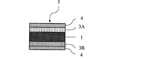
- FIG. 1 is a schematic cross-sectional view showing an example of a double-sided pressure-sensitive adhesive tape used in the method for producing an organic EL panel according to the present invention.
- Adhesive layers 3A and 3B are provided on both sides of a base material layer 1,
- a separator 4 is laminated on the layers 3A and 3B.
- FIG. 2 is a schematic cross-sectional view showing another example of the double-sided pressure-sensitive adhesive tape used in the method for producing an organic EL panel according to the present invention.
- Adhesive layers 3A and 3B are provided, and a separator 4 is laminated on the adhesive layers 3A and 3B.
- the method for producing an organic electroluminescence panel according to the present invention comprises a method for producing an organic electroluminescence panel in which an organic electroluminescence element is formed on a ultrathin glass substrate having a thickness of 10 to 150 ⁇ m by a vacuum deposition method. Is temporarily fixed to a support plate via a double-sided pressure-sensitive adhesive tape having a heat-peelable pressure-sensitive adhesive layer containing thermally expandable microspheres that start expansion and / or foaming at a temperature higher than the vacuum deposition temperature on at least one side. An electrode is formed on an ultrathin glass substrate.
- the double-sided pressure-sensitive adhesive tape of the present invention has a base material layer from the viewpoint of handling properties, processability, etc., and heat that starts expansion and / or foaming at a temperature higher than the vacuum deposition temperature on at least one side of the base material layer. It has a heat-peelable pressure-sensitive adhesive layer containing expandable microspheres. Moreover, the adhesive layer of the double-sided pressure-sensitive adhesive sheet of the present invention may be protected by being attached with a separator (release liner) until use.
- the pressure-sensitive adhesive layer on at least one side may be a heat-peelable pressure-sensitive adhesive layer.
- the pressure-sensitive adhesive layers on both sides of the double-sided pressure-sensitive adhesive tape are heat-peelable pressure-sensitive adhesive layers.
- the pressure-sensitive adhesive layer on one side of the double-sided pressure-sensitive adhesive tape (particularly, the layer having a surface to be attached to an ultrathin glass substrate) is a heat-peelable pressure-sensitive adhesive layer, and the pressure-sensitive adhesive layer on the other side is a thermally expandable micro It may be a pressure-sensitive adhesive layer or an active energy ray-curable pressure-sensitive adhesive layer that does not contain spheres.
- the double-sided pressure-sensitive adhesive tape of the present invention among other things, the adhesiveness on both sides of the double-sided pressure-sensitive adhesive tape can be remarkably reduced in one step of heat treatment, and the organic EL panel and the support plate are peeled from the double-sided pressure-sensitive adhesive tape. Therefore, it is preferable to have a heat-peelable pressure-sensitive adhesive layer containing thermally expandable microspheres on both sides of the double-sided pressure-sensitive adhesive tape.
- the double-sided pressure-sensitive adhesive tape is used, the energy cost at the time of peeling can be reduced, and the peeling work can be simplified.
- the heat-peelable pressure-sensitive adhesive layer of the present invention contains a pressure-sensitive adhesive for imparting adhesiveness in addition to the thermally expandable microspheres.
- a pressure-sensitive adhesive for imparting adhesiveness in addition to the thermally expandable microspheres.
- the heat-peelable pressure-sensitive adhesive layer is preferably located on the surface layer (outermost layer) of the double-sided pressure-sensitive adhesive tape, but may be located on an inner layer other than the surface layer. In that case, other layers such as a contamination prevention layer may be provided on the heat-peelable pressure-sensitive adhesive layer.
- the pressure-sensitive adhesive is preferably one that does not restrain the expansion and / or foaming of the thermally expandable microspheres as much as possible during heating.
- the adhesive include rubber adhesives, acrylic adhesives, vinyl alkyl ether adhesives, silicone adhesives, polyester adhesives, polyamide adhesives, urethane adhesives, and styrene-diene block copolymers.
- One or a combination of two or more known pressure-sensitive adhesives such as system-type pressure-sensitive adhesives and those having a melting point of about 200 ° C. or less and a melt-meltable resin blended therein can be used. (For example, see JP-A-56-61468, JP-A-63-30205, JP-A-63-17981, etc.).
- the adhesive is a crosslinking agent (eg, polyisocyanate, alkyl etherified melamine compound, etc.), tackifier (eg, rosin derivative resin, polyterpene resin, petroleum resin, oil-soluble phenol) Resin, etc.), plasticizers, fillers, anti-aging agents and other suitable additives may be included.
- a crosslinking agent eg, polyisocyanate, alkyl etherified melamine compound, etc.
- tackifier eg, rosin derivative resin, polyterpene resin, petroleum resin, oil-soluble phenol) Resin, etc.
- plasticizers eg, rosin derivative resin, polyterpene resin, petroleum resin, oil-soluble phenol Resin, etc.
- fillers e.g, anti-aging agents and other suitable additives may be included.
- the pressure-sensitive adhesive is a rubber-based pressure-sensitive adhesive based on natural rubber or various synthetic rubbers; (meth) acrylic acid alkyl esters (for example, methyl ester, ethyl ester, propyl ester, isopropyl ester, butyl ester, Isobutyl ester, s-butyl ester, t-butyl ester, pentyl ester, hexyl ester, heptyl ester, octyl ester, 2-ethylhexyl ester, isooctyl ester, isodecyl ester, dodecyl ester, tridecyl ester, pentadecyl ester, hexa decyl ester, heptadecyl ester, octadecyl ester, nonadecyl ester, Accession used as monomer components one or more of C, such as 1-20 alky
- the acrylic polymer may be mixed with other monomer components copolymerizable with the (meth) acrylic acid alkyl ester as necessary for the purpose of modifying cohesion, heat resistance, crosslinkability, and the like. Corresponding units may be included.
- monomer components include carboxyl group-containing monomers such as acrylic acid, methacrylic acid, carboxyethyl acrylate, carboxypentyl acrylate, itaconic acid, maleic acid, fumaric acid, and crotonic acid; maleic anhydride, itaconic anhydride Acid anhydride monomers such as hydroxyethyl (meth) acrylate, hydroxypropyl (meth) acrylate, hydroxybutyl (meth) acrylate, hydroxyhexyl (meth) acrylate, hydroxyoctyl (meth) acrylate, (meth) Hydroxyl group-containing monomers such as hydroxydecyl acrylate, hydroxylauryl (meth) acryl
- (Meta) Acry Acid alkoxyalkyl monomers maleimide monomers such as N-cyclohexylmaleimide, N-isopropylmaleimide, N-laurylmaleimide, N-phenylmaleimide; N-methylitaconimide, N-ethylitaconimide, N-butylitaconimide, N -Itacimide monomers such as octylitaconimide, N-2-ethylhexylitaconimide, N-cyclohexylitaconimide, N-laurylitaconimide; N- (meth) acryloyloxymethylenesuccinimide, N- (meth) acryloyl-6-oxy Succinimide monomers such as hexamethylene succinimide and N- (meth) acryloyl-8-oxyoctamethylene succinimide; vinyl acetate, vinyl propionate, N-vinyl pyrrolide ,
- a more preferable pressure-sensitive adhesive has a dynamic elastic modulus in the range of 5000 to 1,000,000 Pa from room temperature to 150 ° C.
- a pressure sensitive adhesive based on a polymer is preferable.
- Examples of the heat-expandable microspheres used in the heat-peelable pressure-sensitive adhesive layer include microspheres in which a substance that easily gasifies and expands by heating, such as isobutane, propane, and pentane, is encapsulated in an elastic shell. I just need it.
- the shell is often formed of a hot-melt material or a material that is destroyed by thermal expansion.
- Examples of the substance forming the shell include vinylidene chloride-acrylonitrile copolymer, polyvinyl alcohol, polyvinyl butyral, polymethyl methacrylate, polyacrylonitrile, polyvinylidene chloride, and polysulfone.
- Thermally expandable microspheres can be produced by a conventional method such as a coacervation method or an interfacial polymerization method.
- a conventional method such as a coacervation method or an interfacial polymerization method.
- commercially available products such as trade names “Microsphere F30D, F50D” manufactured by Matsumoto Yushi Seiyaku Co., Ltd. can be used.
- each heat-peelable pressure-sensitive adhesive layer has thermally expandable microspheres that expand and / or foam at the same temperature. It may contain, and may contain thermally expandable microspheres that expand and / or foam at different temperatures, among which thermally expandable microspheres that expand and / or foam at the same temperature. It is preferable to contain a sphere.
- a thermally expandable microscopic material having an appropriate strength that does not rupture until the volume expansion coefficient is 5 times or more, especially 7 times or more, particularly 10 times or more.
- a sphere is preferred.
- the amount of thermally expandable microspheres can be appropriately set according to the expansion ratio of the pressure-sensitive adhesive layer and the decrease in pressure-sensitive adhesive strength (adhesive strength).
- the base polymer that forms the heat-peelable pressure-sensitive adhesive layer For example, in the case of an acrylic adhesive, the amount is, for example, 1 to 150 parts by weight, preferably 5 to 100 parts by weight with respect to 100 parts by weight of the acrylic polymer). If the amount of the thermally expandable microsphere is less than 1 part by weight, sufficient peelability may not be exhibited. On the other hand, if the amount exceeds 150 parts by weight, the pressure-sensitive adhesive layer surface is uneven. Adhesiveness may be reduced.
- the ultrathin glass substrate can be easily peeled off after the manufacturing process, and when the heat-peelable pressure-sensitive adhesive layer is thinly formed, the amount of thermally expandable microspheres is reduced to some extent. It is preferable to suppress it in order to stably form the surface state. From this point, the blending amount (30 to 80 parts by weight) which is about half of the blending amount necessary for complete peeling (adhesion becomes zero) is optimal.
- the thermal expansion start temperature of the heat-peelable pressure-sensitive adhesive layer of the present invention is appropriately determined according to the vacuum deposition temperature at the time of forming the organic EL element, and the temperature at which expansion and / or foaming of the thermally expandable microspheres starts is vacuum deposition.
- the temperature is preferably 20 ° C. or higher (preferably 50 ° C. or higher, particularly preferably 70 ° C. or higher) higher than the temperature.
- the thermal expansion start temperature is 130 to 250 ° C., preferably 150 to 230 ° C.
- the thermal expansion start temperature is less than 130 ° C., for example, off-gas is released from the thermally expandable microspheres by heating when forming the organic EL element by vacuum deposition, and the vacuum degree in the vacuum chamber is reduced or the specified vacuum degree is reached. There is a delay in the arrival time, and the film accuracy and productivity tend to be remarkably lowered.
- the thermal expansion start temperature exceeds 250 ° C., it is necessary to apply a high temperature in order to develop easy peelability in the peeling process, and thus the organic EL panel may be damaged due to heat deformation.
- the “thermal expansion start temperature” in the present invention refers to a thermal expansion apparatus (product name “TMA / SS6100” manufactured by SII / Nanotechnology Co., Ltd.) using a thermal expansion microsphere, and an expansion method (load: It is the temperature at which expansion and / or foaming of the thermally expandable microsphere started when measured at 19.6 N, probe: 3 mm ⁇ .
- the above-mentioned thermal expansion start temperature can be appropriately controlled depending on the type of the thermally expandable microsphere, the particle size distribution, and the like. In particular, it can be easily controlled by classifying the thermally expandable microspheres and sharpening the particle size distribution of the thermally expandable microspheres used.
- a classification method a known method can be used, and either a dry method or a wet method may be used.
- the classification device include known classification devices such as a gravity classifier, an inertia classifier, and a centrifugal classifier. Can be used.
- a coating liquid containing a pressure-sensitive adhesive and thermally expandable microspheres is prepared using a solvent as necessary, and this is applied to the base material layer or the rubbery organic elastic layer.
- a coating liquid containing a pressure-sensitive adhesive and thermally expandable microspheres is prepared using a solvent as necessary, and this is applied to the base material layer or the rubbery organic elastic layer.
- (Dry coating method) Apply the coating agent on an appropriate separator (such as release paper) to form a heat-peelable pressure-sensitive adhesive layer, and transfer (transfer) it onto the base material layer or rubber-like organic elastic layer )
- Dry lamination method a method of co-extruding a resin composition containing the constituent material of the base material layer and a resin composition containing the heat-peelable pressure-sensitive adhesive layer forming material (co-extrusion method), etc. Can be done by the method.
- the heat-peelable pressure-sensitive adhesive layer may be either a single layer or multiple layers.
- the thickness of the heat-peelable pressure-sensitive adhesive layer may be thicker than the maximum particle size of the thermally expandable microspheres contained, and is, for example, about 5 to 300 ⁇ m, preferably about 10 to 100 ⁇ m. If the thickness is excessive, cohesive failure may occur at the time of peeling after the heat treatment, adhesive residue may be generated on the organic EL panel, and the peelability may be lowered. On the other hand, if the thickness is too small, the unevenness of the heat-expandable microspheres impairs the surface smoothness and lowers the adhesiveness.
- the degree of deformation of the heat-peelable pressure-sensitive adhesive layer due to heat treatment is small, the adhesive force is difficult to smoothly decline, and in addition, in order to maintain the adhesiveness during temporary fixation, It may be necessary to make the particle size too small.
- the pressure-sensitive adhesive layer contained in the pressure-sensitive adhesive layer is not particularly limited, and those exemplified in the heat-peelable pressure-sensitive adhesive layer can be suitably used.
- a coating liquid containing a pressure-sensitive adhesive is prepared using a solvent as necessary, and this is applied to a base material layer or a rubbery organic elastic layer (dry coating method).
- a method of forming the pressure-sensitive adhesive layer on a transparent separator (such as release paper) to form a pressure-sensitive adhesive layer, and transferring (transferring) it onto the base layer or rubber-like organic elastic layer dry lamination method
- the resin composition containing the constituent material of the base material layer and the resin composition containing the pressure-sensitive adhesive layer forming material can be co-extruded by an appropriate method such as a method (co-extrusion method).
- the pressure-sensitive adhesive layer may be either a single layer or multiple layers.
- the active energy ray-curable pressure-sensitive adhesive layer has a characteristic of being cured by irradiation with active energy rays. In order to develop the active energy ray curability, it is sufficient if it has a polymerizable carbon-carbon double bond. For example, a polymer having a polymerizable carbon-carbon double bond at the side chain or terminal is used as a base polymer. Active energy ray curable pressure sensitive adhesives may be used, and additive type active energy ray curable pressure sensitive adhesives in which a monomer component or oligomer component having a polymerizable carbon-carbon double bond side chain is added to the pressure sensitive adhesive are used. May be.
- the active energy ray refers to, for example, ultraviolet rays, visible rays, infrared rays, radiation, and the like.
- Examples of the active energy ray-curable pressure-sensitive adhesive having a polymer having a polymerizable carbon-carbon double bond at the side chain or terminal as a base polymer include, for example, a rubber-based pressure-sensitive adhesive, an acrylic pressure-sensitive adhesive, and a vinyl alkyl ether type.
- the adhesive is a crosslinking agent (eg, polyisocyanate, alkyl etherified melamine compound, etc.), tackifier (eg, rosin derivative resin, polyterpene resin, petroleum resin, oil-soluble phenol) Resin, etc.), plasticizers, fillers, anti-aging agents and other suitable additives may be included.
- a crosslinking agent eg, polyisocyanate, alkyl etherified melamine compound, etc.
- tackifier eg, rosin derivative resin, polyterpene resin, petroleum resin, oil-soluble phenol) Resin, etc.
- plasticizers eg, rosin derivative resin, polyterpene resin, petroleum resin, oil-soluble phenol Resin, etc.
- fillers e.g, anti-aging agents and other suitable additives may be included.
- the adhesive component (base polymer) can be obtained by using the acrylic copolymer as a basic skeleton and introducing a polymerizable carbon-carbon double bond into the basic skeleton.
- an active energy ray-curable monomer or oligomer component may or may not be added separately.
- the acrylic polymer having a polymerizable carbon-carbon double bond does not need to contain an oligomer component or the like that is a low molecular component at all or may not contain a large amount.
- a pressure-sensitive adhesive layer having a stable layer structure can be formed without moving through the inside.
- the method for introducing a polymerizable carbon-carbon double bond into the acrylic copolymer is not particularly limited, and various methods can be employed. For example, after a monomer having a functional group is previously copolymerized as an acrylic copolymer, a compound having a functional group capable of reacting with the functional group and a polymerizable carbon-carbon double bond is converted into a polymerizable carbon-carbon double bond. Examples of the method include condensation or addition reaction while maintaining the active energy ray curability of the bond.
- Examples of combinations of highly reactive functional groups include carboxylic acid groups and epoxy groups, carboxylic acid groups and aziridine groups, hydroxyl groups and isocyanate groups, and the like.
- a combination of a hydroxyl group and an isocyanate group is preferable because of easy tracking of the reaction.
- each functional group may be on either side of the acrylic copolymer and the compound having the functional group and a polymerizable carbon-carbon double bond. It is preferable that the acrylic copolymer has a hydroxyl group and the compound having the functional group and the polymerizable carbon-carbon double bond has an isocyanate group.
- examples of the compound having a functional group and a polymerizable carbon-carbon double bond include methacryloisocyanate, 2-methacryloyloxyethyl isocyanate, m-isopropenyl- ⁇ , ⁇ -dimethylbenzyl isocyanate, and the like.
- examples of the acrylic copolymer those obtained by copolymerizing the above-exemplified hydroxyl group-containing monomers and ether compounds such as 2-hydroxyethyl vinyl ether, 4-hydroxybutyl vinyl ether, and diethylene glycol monovinyl ether are used.
- the acrylic copolymer having a polymerizable carbon-carbon double bond can be used alone or in combination of two or more.
- the additive-type active energy ray-curable pressure-sensitive adhesive in which a monomer component or oligomer component having a polymerizable carbon-carbon double bond side chain is blended with the above-mentioned pressure-sensitive adhesive is an active energy ray-curable monomer component or oligomer component. It can be obtained by blending.
- an adhesive an acrylic adhesive is preferable.
- the active energy ray-curable monomer component or oligomer component a monomer or oligomer having a functional group having a property of crosslinking by irradiation with active energy rays such as a carbon-carbon double bond can be used.
- monomers or oligomers containing an average of 6 or more carbon-carbon double bonds in one molecule are preferable.
- Examples of the monomer or oligomer include trimethylolpropane tri (meth) acrylate, pentaerythritol tri (meth) acrylate, dipentaerythritol hexa (meth) acrylate, tetraethylene glycol di (meth) acrylate, 1,6- Hexanediol (meth) acrylate, neopentyl glycol di (meth) acrylate, esterified product of (meth) acrylic acid and polyhydric alcohol, ester acrylate oligomer, 2-propenyl-3-butenyl cyanurate, isocyanurate, isocyanurate Compounds and the like. Of these, dipentaerythritol hexa (meth) acrylate is preferable.
- the active energy ray-curable monomer component and oligomer component may be used alone or in admixture of two or more.
- the active energy ray-curable pressure-sensitive adhesive layer is prepared, for example, by preparing a coating liquid containing a pressure-sensitive adhesive using a solvent as necessary, and applying this onto a base material layer or a rubbery organic elastic layer (dry coating method). ), Coating the coating agent on an appropriate separator (such as release paper) to form an active energy ray-curable pressure-sensitive adhesive layer, and transferring (transferring) it onto the base material layer or rubber-like organic elastic layer.
- an appropriate separator such as release paper
- Appropriate methods such as a method (dry lamination method), a method of co-extruding a resin composition containing the constituent material of the base material layer and the resin composition containing the active energy ray-curable pressure-sensitive adhesive layer forming material (co-extrusion method) Can be done by the method.
- the active energy ray-curable pressure-sensitive adhesive layer may be either a single layer or multiple layers.
- the substrate constituting the substrate layer is not particularly limited, and various substrates can be used.
- fiber-based substrates such as cloth, nonwoven fabric, felt, and net
- paper-based materials such as various papers Base materials
- Metal base materials such as metal foils and metal plates
- Plastic base materials such as films and sheets made of various resins
- Rubber base materials such as rubber sheets
- Foams such as foam sheets and laminates thereof Any suitable thin leaf body can be used.
- the material or material of the plastic base material examples include polyester (polyethylene terephthalate, polyethylene naphthalate, polybutylene terephthalate, polybutylene naphthalate, etc.), polyolefin (polyethylene, polypropylene, ethylene-propylene copolymer, etc.), polyvinyl, and the like. Alcohol, polyvinylidene chloride, polyvinyl chloride, vinyl chloride-vinyl acetate copolymer, polyvinyl acetate, polyamide, polyimide, cellulose, fluororesin, polyether, polystyrene resin (polystyrene, etc.), polycarbonate, polyethersulfone Etc.
- the base material layer may have a single layer form or may have a multiple layer form.
- the thickness of the base material layer is not particularly limited, but is preferably 500 ⁇ m or less, more preferably about 5 to 250 ⁇ m.
- the surface of the base material layer is subjected to conventional surface treatments such as chromic acid treatment, ozone exposure, flame exposure, and high-voltage impact exposure, in order to enhance adhesion to the heat-peelable pressure-sensitive adhesive layer, etc., if necessary. Further, oxidation treatment or the like by a chemical or physical method such as ionizing radiation treatment may be performed.
- the double-sided pressure-sensitive adhesive tape of the present invention preferably has a rubbery organic elastic layer between the base material layer and the pressure-sensitive adhesive layer located on both surfaces of the base material layer.
- the rubbery organic elastic layer has a function of increasing the adhesion area by causing the surface of the double-sided pressure-sensitive adhesive tape to follow the surface shape of the ultra-thin glass substrate well when bonding the double-sided pressure-sensitive adhesive tape to the ultrathin glass substrate,
- the heat-peelable pressure-sensitive adhesive layer has a function of promoting the formation of a wavy structure due to a three-dimensional structural change.
- the rubber-like organic elastic layer is provided with the above-described functions.
- natural rubber, synthetic rubber, or synthetic resin having rubber elasticity having a D-type Sure D-type hardness of 50 or less, particularly 40 or less based on ASTM D-2240. It is preferable to form.
- the synthetic rubber or synthetic resin having rubber elasticity examples include, for example, synthetic rubbers such as nitriles, dienes, and acrylics; thermoplastic elastomers such as polyolefins and polyesters; ethylene-vinyl acetate copolymers, polyurethanes, and polybutadienes. And a synthetic resin having rubber elasticity such as soft polyvinyl chloride.
- essentially a hard polymer such as polyvinyl chloride can exhibit rubber elasticity when combined with a compounding agent such as a plasticizer or a softening agent. It can be used as a constituent material of the organic elastic layer.
- the adhesive which comprises the above-mentioned heat peelable adhesive layer can also be used preferably as a constituent material of a rubber-like organic elastic layer.
- the thickness of the rubbery organic elastic layer is generally about 5 to 300 ⁇ m, preferably about 5 to 100 ⁇ m. If the thickness is excessive, the heat-peelable pressure-sensitive adhesive layer is inhibited from changing three-dimensionally in the peeling step, and the peelability tends to be lowered.
- the rubber-like organic elastic layer is formed by, for example, applying a coating liquid containing a rubber-like organic elastic layer forming material such as natural rubber, synthetic rubber, or synthetic resin having rubber elasticity onto the base material layer (coating method).
- a coating liquid containing a rubber-like organic elastic layer forming material such as natural rubber, synthetic rubber, or synthetic resin having rubber elasticity onto the base material layer (coating method).
- the film made of the rubber-like organic elastic layer forming material or the laminated film in which the layer made of the rubber-like organic elastic layer forming material is previously formed on one or more heat-peelable pressure-sensitive adhesive layers is bonded to the base material layer. It is carried out by an appropriate method such as a method (dry lamination method), a method of co-extruding a resin composition containing a constituent material of a base material layer and a resin composition containing the rubber-like organic elastic layer forming material (co-extrusion method). be able to.
- the rubbery organic elastic layer forming material includes, for example, a filler, a flame retardant, an anti-aging agent, an antistatic agent, a softening agent, an ultraviolet absorber, an antioxidant, a plasticizer, and a surface active agent.
- a filler for example, a flame retardant, an anti-aging agent, an antistatic agent, a softening agent, an ultraviolet absorber, an antioxidant, a plasticizer, and a surface active agent.
- a flame retardant for example, a flame retardant, an anti-aging agent, an antistatic agent, a softening agent, an ultraviolet absorber, an antioxidant, a plasticizer, and a surface active agent.
- the double-sided pressure-sensitive adhesive tape of the present invention may be provided with a separator (release liner) on the surface of the pressure-sensitive adhesive layer from the viewpoint of protecting the pressure-sensitive adhesive layer surface and preventing blocking.
- the separator is peeled off when the double-sided pressure-sensitive adhesive tape is attached to the adherend, and is not necessarily provided.
- the separator to be used is not particularly limited, and a known and commonly used release paper or the like can be used.
- a substrate having a release layer such as a plastic film or paper surface-treated with a release agent such as silicone, long-chain alkyl, fluorine, or molybdenum sulfide; polytetrafluoroethylene, polychlorotrifluoroethylene, polyfluoride Low-adhesive substrate made of a fluoropolymer such as vinyl fluoride, polyvinylidene fluoride, tetrafluoroethylene / hexafluoropropylene copolymer, chlorofluoroethylene / vinylidene fluoride copolymer; olefin resin (eg, polyethylene, polypropylene) Etc.) and the like can be used.
- a release layer such as a plastic film or paper surface-treated with a release agent such as silicone, long-chain alkyl, fluorine, or molybdenum sulfide
- a release agent such as silicone, long-chain alkyl, fluorine, or mo
- the separator may be provided on both surfaces of the double-sided pressure-sensitive adhesive tape of the present invention, or a separator having a back release layer is provided on one side of the pressure-sensitive adhesive surface, and the sheet is wound on the opposite side of the pressure-sensitive adhesive surface. You may make it the back surface peeling layer of a separator contact.
- the double-sided pressure-sensitive adhesive tape of the present invention has a heat-peelable pressure-sensitive adhesive layer containing thermally expandable microspheres on at least one side of the base material layer, it has excellent adhesive force before heat treatment, An ultrathin glass substrate can be held and temporarily fixed, and the organic EL panel can be processed smoothly. And when the double-sided pressure-sensitive adhesive tape is no longer necessary, the heat-expandable pressure-sensitive adhesive layer is three-dimensionally formed by expanding and / or foaming the heat-expandable microspheres by heating at a temperature equal to or higher than a predetermined temperature.
- the double-sided pressure-sensitive adhesive tape of the present invention can be suitably used as a temporary fixing tape in the production process of an organic EL panel.
- the organic EL panel manufacturing method according to the present invention is characterized in that an organic EL element is formed on an ultrathin glass substrate in a state where the ultrathin glass substrate is temporarily fixed to a support plate with the double-sided adhesive tape.
- the material constituting the support plate for temporarily fixing the ultra-thin glass substrate is not particularly limited as long as it can hold the ultra-thin glass substrate to be bonded together, but a hard material is preferably used rather than the ultra-thin glass substrate. Examples thereof include silicon, glass, SUS plate, copper plate, and acrylic plate.
- the thickness of the support plate is preferably, for example, 0.4 mm or more (for example, 0.4 to 5.0 mm).
- the support plate and the ultrathin glass substrate can be adhered to each other, for example, using a roller, a spatula, a press machine, or the like. Can be matched.
- the ultrathin glass substrate may be a colorless and transparent glass, and the thickness thereof is, for example, about 10 to 150 ⁇ m, preferably about 10 to 70 ⁇ m, and particularly preferably about 20 to 50 ⁇ m. If the thickness of the ultra-thin glass substrate exceeds 150 ⁇ m, it tends to be difficult to exhibit sufficient flexibility. On the other hand, if the thickness of the ultra-thin glass substrate is less than 10 ⁇ m, it is basically difficult to manufacture. It is.
- An organic EL element consists of anode / hole injection layer / hole transport layer / light emitting layer / hole blocking layer / electron transport layer / cathode, for example.
- a method for forming the organic EL element for example, PVD (physical vapor deposition) is performed so that a thin film made of a material for an anode (for example, indium tin oxide: ITO) is 1 ⁇ m or less, preferably 10 to 200 nm.
- the anode is formed by a vacuum evaporation method such as a CVD method or a chemical vapor deposition (CVD) method.
- the deposition temperature in the vacuum deposition method is, for example, about 70 to 250 ° C.
- the degree of vacuum is, for example, about 10 ⁇ 2 to 10 ⁇ 6 Pa
- the deposition rate is, for example, about 0.01 to 30 nm / second. is there.
- a method for thinning the organic compound thin film there are wet processes (spin coating method, casting method, ink jet method, printing method), etc., but it is easy to obtain a uniform film and pinholes are not easily generated. From the point of view, a vacuum deposition method, a spin coating method, an ink jet method, and a printing method are particularly preferable.
- a PVD (physical vapor deposition) method or a CVD (chemical vapor deposition) method is used so that a thin film made of a cathode material is formed on the organic compound thin film to a thickness of 1 ⁇ m or less, preferably in the range of 50 to 200 nm.
- An organic EL element is formed by producing a cathode by a vacuum evaporation method such as an evaporation method.
- the adhesive strength of the double-sided pressure-sensitive adhesive tape is reduced to peel the organic EL panel from the support plate.
- the heat-expandable microspheres contained in the heat-peelable pressure-sensitive adhesive layer constituting the double-sided pressure-sensitive adhesive tape are expanded and / or foamed to give a remarkable adhesive force.
- the organic EL panel can be peeled off from the support plate by lowering.
- the peeled organic EL panel is collected by a well-known and commonly used method.
- the heating means it is only necessary to heat the double-sided adhesive tape to rapidly expand and / or foam the thermally expandable microspheres contained therein.
- an electric heater dielectric heating; magnetic heating; near infrared, mid infrared Heating by electromagnetic waves such as far infrared rays; ovens, hot plates, etc. can be used without particular limitation.
- the heating temperature may be higher than the temperature at which the thermally expandable microspheres contained in the double-sided pressure-sensitive adhesive tape start to expand and / or foam, and is, for example, about 130 to 250 ° C., preferably about 150 to 230 ° C.
- the ITO electrode was formed under the following conditions. Degree of vacuum: 1 ⁇ 10 -5 Pa Target: 90% indium oxide, 10% tin oxide Argon gas pressure: 2 ⁇ 10 -2 Torr Bias voltage: -500V Substrate temperature: 110 ° C Sputtering time: 10 minutes (15 ⁇ m, 1 mm pitch)
- Example 1 2-ethylhexyl acrylate / ethyl acrylate / methyl methacrylate / -2-hydroxyethyl acrylate (30 parts by weight / 70 parts by weight / 5 parts by weight / 5 parts by weight) copolymer-based pressure sensitive adhesive 100 parts by weight, A toluene solution containing 1 part by weight of an isocyanate-based cross-linking agent is applied to both sides of a polyester film (thickness: 100 ⁇ m) as a base so that the thickness after drying is 20 ⁇ m, and dried to form a rubbery organic elastic layer A , B was obtained.
- a sample 1 was obtained by bonding a glass plate (thickness: 1 mm, size: 10 cm ⁇ 10 cm) and an ultrathin glass substrate (thickness: 50 ⁇ m) through the obtained double-sided adhesive tape 1 without bubbles.
- an ITO electrode was formed on the ultrathin glass substrate of Sample 1 obtained by the PVD method (110 ° C.) to obtain an organic EL panel 1 with a glass plate.
- Example 2 A toluene solution containing 100 parts by weight of a pressure-sensitive adhesive copolymer based on 2-ethylhexyl acrylate / ethyl acrylate / acrylic acid (30 parts by weight / 70 parts by weight / 5 parts by weight) and 2 parts by weight of an isocyanate-based crosslinking agent. It apply
- 2-ethylhexyl acrylate / ethyl acrylate / acrylic acid (30 parts by weight / 70 parts by weight / 5 parts by weight) copolymer-based pressure sensitive adhesive 100 parts by weight, isocyanate crosslinking agent 5 parts by weight, thermal expansion So that the thickness after drying a toluene solution containing 30 parts by weight of functional microsphere A (manufactured by Matsumoto Yushi Seiyaku Co., Ltd., trade name “Microsphere F100D”, foaming start temperature: about 170 ° C.) is 30 ⁇ m It is applied onto a separator and dried to obtain a heat-peelable pressure-sensitive adhesive layer C.
- functional microsphere A manufactured by Matsumoto Yushi Seiyaku Co., Ltd., trade name “Microsphere F100D”, foaming start temperature: about 170 ° C.
- the obtained heat-peelable pressure-sensitive adhesive layer C is bonded onto the rubbery organic elastic layer C, and the heat-peelable type is applied to one side of the substrate.
- a double-sided pressure-sensitive adhesive tape 2 having a pressure-sensitive adhesive layer and a pressure-sensitive pressure-sensitive adhesive layer on the other side was obtained.
- Sample 2 and organic EL panel 2 were obtained in the same manner as in Example 1 except that double-sided adhesive tape 2 was used instead of double-sided adhesive tape 1.
- Example 1 is used except that instead of the thermally expandable microsphere A, the thermally expandable microsphere B (manufactured by Matsumoto Yushi Seiyaku Co., Ltd., trade name “Microsphere F50D”, foaming start temperature: about 120 ° C.) is used. Similarly, a double-sided pressure-sensitive adhesive tape 3 was obtained. A glass plate (thickness: 1 mm, size: 10 cm ⁇ 10 cm) and an ultrathin glass substrate (thickness: 50 ⁇ m) were bonded to each other without bubbles through the obtained double-sided adhesive tape 3 to obtain a sample 3. Next, an ITO electrode was formed on the ultrathin glass substrate of Sample 3 obtained by the PVD method (110 ° C.) to obtain an organic EL panel 3 with a glass plate.
- the thermally expandable microsphere B manufactured by Matsumoto Yushi Seiyaku Co., Ltd., trade name “Microsphere F50D”, foaming start temperature: about 120 ° C.
- Comparative Example 2 Instead of using the double-sided adhesive tape 1 when bonding a glass plate (thickness: 1 mm, size: 10 cm ⁇ 10 cm) and an ultra-thin glass substrate (thickness: 50 ⁇ m), pressure-sensitive double-sided adhesive tape (Nitto) Sample 4 was produced in the same manner as in Example 1 except that Denko Corporation, trade name “No. 5000N”) was used. Next, an ITO electrode was formed on the ultrathin glass substrate of Sample 4 obtained by the PVD method (110 ° C.) to obtain an organic EL panel 4 with a glass plate.
- Comparative Example 3 Instead of using double-sided adhesive tape 1 when laminating a glass plate (thickness: 1 mm, size: 10 cm ⁇ 10 cm) and an ultrathin glass substrate (thickness: 50 ⁇ m), wax (Kuju Electric Co., Ltd.) Sample 5 was produced in the same manner as in Example 1 except that the product name “SLOT WAX”) was used. Next, an ITO electrode was formed on the ultrathin glass substrate of Sample 5 obtained by the PVD method (110 ° C.) to obtain an organic EL panel 5 with a glass plate.
- the attached organic EL panel 1 or 2 was subjected to heat treatment, and the organic EL panel was peeled from the glass plate.
- the hot plate set at 120 ° C. is used to heat the organic EL panel 3 with the glass plate.
- the organic EL panel was peeled from the glass plate after the treatment.
- the organic EL panel 4 with a glass plate is heated on a hot plate heated to 60 ° C. The organic EL panel was peeled from the glass plate while being conditioned.
- the organic EL panel 5 with the glass plate is heated and waxed on a hot plate heated to about 80 ° C. With the softened state, a force was applied in the shear direction to peel the organic EL panel from the glass plate. In addition, about the organic EL panel 5 with a glass plate, the wax adhering to the organic EL panel peeled from the glass plate was removed using the solvent (toluene).
- a heat-peelable pressure-sensitive adhesive layer containing thermally expandable microspheres that start expansion and / or foaming at a temperature higher than the vacuum deposition temperature Since it is temporarily fixed with a double-sided pressure-sensitive adhesive tape having an organic EL element, no off-gas is generated when forming the organic EL element, and the organic EL element can be formed by quickly reaching a predetermined degree of vacuum in the vacuum chamber. did it.
- the obtained organic EL panel is peeled from the support plate, it is promptly heated by heating at a temperature equal to or higher than the temperature at which the thermally expandable microspheres contained in the double-sided pressure-sensitive adhesive tape start to expand and / or foam, Moreover, it was possible to peel off without leaving glue, and it was not necessary to clean the back surface of the obtained organic EL panel.
- a double-sided pressure-sensitive adhesive tape containing thermally expandable microspheres that start expansion and / or foaming at a temperature lower than the vacuum deposition temperature off-gas is generated when forming an organic EL element, and a predetermined degree of vacuum It took time to reach.
- the organic EL panel obtained by the method for producing an organic EL panel according to the present invention is useful as a display device, a display, and various light emission sources, and is particularly flexible in the production of an organic EL panel using an ultrathin glass as a substrate. It is possible to produce a long-life display with excellent gas barrier properties.
- Base material layer 2A, 2B Rubbery organic elastic layer 3A, 3B: Adhesive layer 4: Separator 5: Double-sided adhesive tape
Abstract
Description
本発明の両面粘着テープは、ハンドリング性、加工性等の観点から基材層を有し、該基材層の少なくとも一方の側に真空蒸着温度より高い温度で膨張及び/又は発泡を開始する熱膨張性微小球を含有する熱剥離型粘着剤層を有する。また、本発明の両面粘着シートの粘着層は使用までの間、セパレータ(剥離ライナー)が貼着され、保護されていてもよい。
本発明の熱剥離型粘着剤層は、熱膨張性微小球の他、粘着性を付与するための粘着剤を含有する。熱膨張性微小球を含有する熱剥離型粘着剤層は、加熱することにより、含有する熱膨張性微小球が膨張及び/又は発泡し、被着体と粘着剤層との接着面積が著しく減少するため、粘着力を急激に低下させることができる。これにより、未加熱の状態では強接着性を有しながら、剥離を要する場合は加熱により容易に剥離することが可能となる。なお、マイクロカプセル化している発泡剤は、良好な剥離性を安定して発現させることができる。
感圧型接着剤層に含有する粘着成分としては、特に限定されることがなく、上記熱剥離型粘着剤層で例示されたものを好適に使用することができる。感圧型接着剤層は、例えば、必要に応じて溶媒を用いて粘着剤を含むコーティング液を調製し、これを基材層またはゴム状有機弾性層上に塗布する方法(ドライコーティング法)、適当なセパレータ(剥離紙など)上に前記コーティング剤を塗布して感圧型接着剤層を形成し、これを基材層またはゴム状有機弾性層上に転写(移着)する方法(ドライラミネート法)、基材層の構成材料を含む樹脂組成物と前記感圧型接着剤層形成材を含む樹脂組成物とを共押出しする方法(共押出法)などの適宜な方法で行うことができる。なお、感圧型接着剤層は単層、複層の何れであってもよい。
活性エネルギー線硬化型粘着剤層は、活性エネルギー線照射により硬化する性質を有することを特徴としている。活性エネルギー線硬化性を発現させるには、重合性炭素-炭素二重結合を有していればよく、例えば、側鎖、又は、末端に重合性炭素-炭素二重結合を有するポリマーをベースポリマーとした活性エネルギー線硬化型粘着剤を使用してもよく、粘着剤に重合性炭素-炭素二重結合側鎖を有するモノマー成分やオリゴマー成分を配合した添加型活性エネルギー線硬化型粘着剤を使用してもよい。本発明において活性エネルギー線とは、例えば、紫外線、可視光線、赤外線、放射線等をいう。
基材層を構成する基材としては、特に限定されず、各種基材を用いることが可能であり、例えば、布、不織布、フェルト、ネットなどの繊維系基材;各種の紙などの紙系基材;金属箔、金属板などの金属系基材;各種樹脂によるフィルムやシートなどのプラスチック系基材;ゴムシートなどのゴム系基材;発泡シートなどの発泡体や、これらの積層体等の適宜な薄葉体を用いることができる。上記プラスチック系基材の材質又は素材としては、例えば、ポリエステル(ポリエチレンテレフタレート、ポリエチレンナフタレート、ポリブチレンテレフタレート、ポリブチレンナフタレートなど)、ポリオレフィン(ポリエチレン、ポリプロピレン、エチレン-プロピレン共重合体など)、ポリビニルアルコール、ポリ塩化ビニリデン、ポリ塩化ビニル、塩化ビニル-酢酸ビニル共重合体、ポリ酢酸ビニル、ポリアミド、ポリイミド、セルロース類、フッ素系樹脂、ポリエーテル、ポリスチレン系樹脂(ポリスチレンなど)、ポリカーボネート、ポリエーテルスルホンなどが挙げられる。なお、基材層は単層の形態を有していてもよく、また、複層の形態を有していてもよい。
本発明の両面粘着テープには、基材層と該基材層の両面に位置する粘着剤層との間に、ゴム状有機弾性層を有することが好ましい。ゴム状有機弾性層は、両面粘着テープを極薄ガラス基板に接着する際に、両面粘着テープの表面を極薄ガラス基板の表面形状に良好に追従させて、接着面積を大きくするという機能と、加熱剥離する際に、熱剥離型粘着剤層が三次元的構造変化することによるうねり構造の形成を助長する機能とを有する。
本発明の両面粘着テープには、粘着剤層表面の保護、ブロッキング防止の観点などから、粘着剤層表面にセパレータ(剥離ライナー)が設けられていてもよい。セパレータは両面粘着テープを被着体に貼着する際に剥がされるものであり、必ずしも設けなくてもよい。用いられるセパレータとしては、特に限定されず、公知慣用の剥離紙などを使用できる。例えば、シリコーン系、長鎖アルキル系、フッ素系、硫化モリブデン系等の剥離剤により表面処理されたプラスチックフィルムや紙等の剥離層を有する基材;ポリテトラフルオロエチレン、ポリクロロトリフルオロエチレン、ポリフッ化ビニル、ポリフッ化ビニリデン、テトラフルオロエチレン・ヘキサフルオロプロピレン共重合体、クロロフルオロエチレン・フッ化ビニリデン共重合体等のフッ素系ポリマーからなる低接着性基材;オレフィン系樹脂(例えば、ポリエチレン、ポリプロピレンなど)等の無極性ポリマーからなる低接着性基材などを用いることができる。
本発明に係る有機ELパネルの製造方法は、極薄ガラス基板を上記両面粘着テープで支持板に仮固定した状態で、該極薄ガラス基板上に有機EL素子を形成することを特徴とする。
真空度:1×10⁻⁵Pa
ターゲット:90%酸化インジウム、10%酸化スズ
アルゴンガス圧:2×10⁻²Torr
バイアス電圧:-500V
基板温度:110℃
スパッタリング時間:10分(15μm、1mmピッチ)
アクリル酸-2-エチルヘキシル/アクリル酸エチル/メタクリル酸メチル/アクリル酸-2-ヒドロキシエチル(30重量部/70重量部/5重量部/5重量部)共重合体系感圧型接着剤100重量部、イソシアネート系架橋剤1重量部を配合したトルエン溶液を乾燥後の厚さが20μmとなるように基剤としてのポリエステルフィルム(厚さ:100μm)の両面に塗布、乾燥し、ゴム状有機弾性層A、Bを得た。
次に、アクリル酸-2-エチルヘキシル/アクリル酸エチル/メタクリル酸メチル/アクリル酸-2-ヒドロキシエチル(30重量部/70重量部/5重量部/5重量部)共重合体系感圧型接着剤100重量部、イソシアネート系架橋剤2重量部、熱膨張性微小球A(松本油脂製薬(株)製、商品名「マイクロスフェアー F100D」、発泡開始温度:約170℃)30重量部を配合したトルエン溶液を乾燥後の厚さが30μmとなるようにセパレータ上に塗布、乾燥し、熱剥離型粘着剤層A、Bを得、得られた熱剥離型粘着剤層A、Bを上記ゴム状有機弾性層A、B上にそれぞれ貼り合わせて、基材の両側に熱剥離型粘着剤層を有する両面粘着テープ1を得た。
アクリル酸-2-エチルヘキシル/アクリル酸エチル/アクリル酸(30重量部/70重量部/5重量部)共重合体系感圧型接着剤100重量部、イソシアネート系架橋剤2重量部を配合したトルエン溶液を乾燥後の厚さが20μmとなるように基剤としてのポリエステルフィルム(厚さ:100μm)の両面に塗布、乾燥し、ゴム状有機弾性層C、Dを得た。
次に、アクリル酸-2-エチルヘキシル/アクリル酸エチル/アクリル酸(30重量部/70重量部/5重量部)共重合体系感圧型接着剤100重量部、イソシアネート系架橋剤5重量部、熱膨張性微小球A(松本油脂製薬(株)製、商品名「マイクロスフェアー F100D」、発泡開始温度:約170℃)30重量部を配合したトルエン溶液を乾燥後の厚さが30μmとなるようにセパレータ上に塗布、乾燥し、熱剥離型粘着剤層Cを得、得られた熱剥離型粘着剤層Cを上記ゴム状有機弾性層C上に貼り合わせて、基材の片側に熱剥離型粘着剤層、もう一方の側に感圧型粘着剤層を有する両面粘着テープ2を得た。
熱膨張性微小球Aの代わりに熱膨張性微小球B(松本油脂製薬(株)製、商品名「マイクロスフェアー F50D」、発泡開始温度:約120℃)を使用した以外は実施例1と同様にして両面粘着テープ3を得た。得られた両面粘着テープ3を介して、ガラス板(厚さ:1mm、サイズ:10cm×10cm)と、極薄ガラス基板(厚さ:50μm)とを気泡なく貼り合わせてサンプル3を得た。
次に、得られたサンプル3の極薄ガラス基板上にITO電極をPVD法(110℃)により形成してガラス板付き有機ELパネル3を得た。
ガラス板(厚さ:1mm、サイズ:10cm×10cm)と、極薄ガラス基板(厚さ:50μm)とを貼り合わせる際に、両面粘着テープ1を使用する代わりに、感圧型両面粘着テープ(日東電工(株)製、商品名「No.5000N」)を使用した以外は実施例1と同様にして、サンプル4を作製した。
次に、得られたサンプル4の極薄ガラス基板上にITO電極をPVD法(110℃)により形成してガラス板付き有機ELパネル4を得た。
ガラス板(厚さ:1mm、サイズ:10cm×10cm)と、極薄ガラス基板(厚さ:50μm)とを貼り合わせる際に、両面粘着テープ1を使用する代わりに、ワックス(九重電気(株)製、商品名「SLOT WAX」)を使用した以外は実施例1と同様にして、サンプル5を作製した。
次に、得られたサンプル5の極薄ガラス基板上にITO電極をPVD法(110℃)により形成してガラス板付き有機ELパネル5を得た。
[オフガス発生量測定]
実施例及び比較例で得られたサンプル1~5について、各サンプルを110℃に加熱した真空チャンバー内に仕込んでから、真空チャンバー内の真空度が1×10⁻⁵Paに到達するまでに要した時間を測定し、各サンプルを真空チャンバー内で110℃に加熱した際に発生したオフガスの発生量を、6×10⁻⁸Paに保った真空チャンバー内でサンプルを110℃に加熱した際の真空度(Pa)により代替評価した。
また、実施例及び比較例で得られたガラス板付き有機ELパネル1~5について、有機EL素子形成後に、ガラス板付き有機ELパネルに関して、有機ELパネルをガラス板から剥離するのに要する時間(秒)、剥離後、有機ELパネル背面を洗浄する必要がある場合は、その洗浄に要する時間(秒)、及び洗浄に使用した溶剤(トルエン)の量(g)を測定した。具体的には、実施例1及び2で得られたガラス板付き有機ELパネル1及び2に関して有機ELパネルをガラス板から剥離する際には、170℃に設定したホットプレートを使用してガラス板付き有機ELパネル1又は2に加熱処理を施して、有機ELパネルをガラス板から剥離した。一方、比較例1で得られたガラス板付き有機ELパネル3に関して有機ELパネルをガラス板から剥離する際には、120℃に設定したホットプレートを使用してガラス板付き有機ELパネル3に加熱処理を施して、有機ELパネルをガラス板から剥離した。また比較例2で得られたガラス板付き有機ELパネル4に関して有機ELパネルをガラス板から剥離する際には、60℃に加熱したホットプレート上でガラス板付き有機ELパネル4を加熱し、しならせながら有機ELパネルをガラス板から剥離した。比較例3で得られたガラス板付き有機ELパネル5に関して有機ELパネルをガラス板から剥離する際には、約80℃に加熱したホットプレート上でガラス板付き有機ELパネル5を加熱してワックスを軟化させた状態で、せん断方向に力を加えて有機ELパネルをガラス板から剥離した。なお、ガラス板付き有機ELパネル5については、ガラス板から剥離した有機ELパネルに付着したワックスを溶剤(トルエン)を使用して除去した。
実施例及び比較例において得られたガラス板付き有機ELパネル1~5を各10個用意し、各ガラス板付き有機ELパネルについて上記剥離性試験を行い、剥離回収された有機ELパネルの破損の有無を目視で観察し、下記式により有機ELパネル回収率(%)を算出した。
回収率(%)={破損することなく剥離回収できた(個)/10(個)}×100

一方、真空蒸着温度より低い温度で膨張及び/又は発泡を開始する熱膨張性微小球を含有する両面粘着テープで仮固定した場合、有機EL素子を形成する際にオフガスが発生し、所定真空度に到達するのに時間を要した。
さらに、熱膨張性微小球を含有しない感圧型両面粘着テープを使用した場合、オフガスが発生することはないが、しかし製造工程後、剥離に時間を要し、その上、破損することなく有機ELパネルを剥離、回収することが困難であった。
さらにまた、両面粘着テープの代わりにワックスを使用した場合、オフガスが発生することはなく、また、得られた有機ELパネルを破損することなく剥離することはできるが、しかし、剥離された有機ELパネル背面に糊残りが発生するため、付着した粘着物質を洗浄するのに時間を要し、その上、多量の洗浄用有機溶剤を要した。
2A、2B:ゴム状有機弾性層
3A、3B:粘着剤層
4:セパレータ
5:両面粘着テープ
Claims (4)
- 厚さ10~150μmの極薄ガラス基板上に真空蒸着法により有機エレクトロルミネッセンス素子を形成する有機エレクトロルミネッセンスパネルの製造方法において、該極薄ガラス基板を、基材層の少なくとも一方の側に真空蒸着温度より高い温度で膨張及び/又は発泡を開始する熱膨張性微小球を含有する熱剥離型粘着剤層を有する両面粘着テープを介して支持板に仮固定し、極薄ガラス基板上に電極を形成する有機エレクトロルミネッセンスパネルの製造方法。
- 両面粘着テープが真空蒸着温度より20℃以上高い温度で膨張及び/又は発泡を開始する熱膨張性微小球を含有する熱剥離型粘着剤層を有する請求項1に記載の有機エレクトロルミネッセンスパネルの製造方法。
- 両面粘着テープの一方の側の粘着剤層が熱剥離型粘着剤層、他方の側の粘着剤層が感圧型接着剤層又は活性エネルギー線硬化型粘着剤層である請求項1又は2に記載の有機エレクトロルミネッセンスパネルの製造方法。
- 両面粘着テープの両側の粘着剤層が熱剥離型粘着剤層である請求項1又は2に記載の有機エレクトロルミネッセンスパネルの製造方法。
Priority Applications (4)
| Application Number | Priority Date | Filing Date | Title |
|---|---|---|---|
| US13/003,269 US8409884B2 (en) | 2008-07-08 | 2009-06-30 | Process for producing organic electroluminescent panel |
| CN2009801250660A CN102077688A (zh) | 2008-07-08 | 2009-06-30 | 有机电致发光面板的制造方法 |
| JP2010519631A JPWO2010004703A1 (ja) | 2008-07-08 | 2009-06-30 | 有機エレクトロルミネッセンスパネルの製造方法 |
| EP09794151A EP2315500A4 (en) | 2008-07-08 | 2009-06-30 | METHOD FOR PRODUCING AN ORGANIC ELECTROLUM NINESCENTER PANEL |
Applications Claiming Priority (2)
| Application Number | Priority Date | Filing Date | Title |
|---|---|---|---|
| JP2008-178181 | 2008-07-08 | ||
| JP2008178181 | 2008-07-08 |
Publications (1)
| Publication Number | Publication Date |
|---|---|
| WO2010004703A1 true WO2010004703A1 (ja) | 2010-01-14 |
Family
ID=41506831
Family Applications (1)
| Application Number | Title | Priority Date | Filing Date |
|---|---|---|---|
| PCT/JP2009/003030 WO2010004703A1 (ja) | 2008-07-08 | 2009-06-30 | 有機エレクトロルミネッセンスパネルの製造方法 |
Country Status (7)
| Country | Link |
|---|---|
| US (1) | US8409884B2 (ja) |
| EP (1) | EP2315500A4 (ja) |
| JP (1) | JPWO2010004703A1 (ja) |
| KR (1) | KR20110039248A (ja) |
| CN (1) | CN102077688A (ja) |
| TW (1) | TW201016071A (ja) |
| WO (1) | WO2010004703A1 (ja) |
Cited By (11)
| Publication number | Priority date | Publication date | Assignee | Title |
|---|---|---|---|---|
| GB2481187A (en) * | 2010-06-04 | 2011-12-21 | Plastic Logic Ltd | Processing flexible display substrates |
| CN102674669A (zh) * | 2011-03-16 | 2012-09-19 | 京东方科技集团股份有限公司 | 一种玻璃基板的固定方法 |
| CN102690066A (zh) * | 2011-03-22 | 2012-09-26 | 京东方科技集团股份有限公司 | 一种玻璃基板的固定方法 |
| JP2013528792A (ja) * | 2010-04-26 | 2013-07-11 | コーニンクレッカ フィリップス エレクトロニクス エヌ ヴィ | 改善された空間利得均一性及び分解能を有するx線検出器及びその製造方法 |
| WO2013146707A1 (ja) * | 2012-03-27 | 2013-10-03 | 日東電工株式会社 | 電子部品切断用加熱剥離型粘着シート及び電子部品加工方法 |
| JP2016042571A (ja) * | 2014-08-13 | 2016-03-31 | Jsr株式会社 | 積層体、基材の処理方法、仮固定用組成物および半導体装置 |
| WO2018034151A1 (ja) * | 2016-08-15 | 2018-02-22 | 日東電工株式会社 | 有機el表示装置用粘着剤組成物、有機el表示装置用粘着剤層、有機el表示装置用粘着剤層付偏光フィルム、及び有機el表示装置 |
| CN110305599A (zh) * | 2019-07-03 | 2019-10-08 | 京东方科技集团股份有限公司 | 一种散热膜及显示装置 |
| WO2020137576A1 (ja) * | 2018-12-26 | 2020-07-02 | Dic株式会社 | フレキシブルディスプレイ用発泡体粘着テープ及びフレキシブルディスプレイ積層物 |
| JP7108164B1 (ja) | 2021-05-27 | 2022-07-28 | 東洋インキScホールディングス株式会社 | 粘着剤、粘着シート、積層体、およびフレキシブルディスプレイ |
| JP7108165B1 (ja) | 2021-05-27 | 2022-07-28 | 東洋インキScホールディングス株式会社 | 粘着剤、粘着シート、積層体、およびフレキシブルディスプレイ |
Families Citing this family (14)
| Publication number | Priority date | Publication date | Assignee | Title |
|---|---|---|---|---|
| CN103568443B (zh) * | 2012-07-19 | 2015-06-17 | 华映视讯(吴江)有限公司 | 玻璃贴合装置 |
| KR101913436B1 (ko) * | 2012-07-26 | 2018-10-30 | 도레이첨단소재 주식회사 | 열박리형 양면 점착 시트 및 이를 이용한 가공방법 |
| US20140287299A1 (en) * | 2013-03-25 | 2014-09-25 | Apple Inc. | Heat-Debonding Adhesives |
| KR101484089B1 (ko) * | 2013-07-16 | 2015-01-19 | 코닝정밀소재 주식회사 | 초박형 유기발광소자 제조방법 |
| CN104031571B (zh) * | 2014-05-17 | 2016-04-13 | 甘春丽 | 一种膨胀易剥离胶带 |
| JP6587811B2 (ja) * | 2015-02-24 | 2019-10-09 | 日東電工株式会社 | 熱剥離型粘着シート |
| CN105845845B (zh) * | 2016-04-14 | 2018-07-06 | 鄂尔多斯市源盛光电有限责任公司 | 一种粘接型阻隔膜的图形化方法、显示面板、显示装置 |
| KR20180063959A (ko) * | 2016-12-02 | 2018-06-14 | 삼성디스플레이 주식회사 | 열박리형 접착 부재 및 이를 포함하는 표시 장치 |
| CN106875851A (zh) * | 2017-04-20 | 2017-06-20 | 京东方科技集团股份有限公司 | 显示装置及其制造方法 |
| TWI681232B (zh) * | 2017-09-26 | 2020-01-01 | 達邁科技股份有限公司 | 用於軟性顯示器之透明聚醯亞胺複合膜及其製造方法 |
| JP6790008B2 (ja) * | 2018-03-14 | 2020-11-25 | 株式会社東芝 | 検出素子および検出器 |
| JP2022502661A (ja) * | 2018-10-03 | 2022-01-11 | ザ・リージェンツ・オブ・ザ・ユニバーシティ・オブ・ミシガンThe Regents Of The University Of Michigan | 超薄紫外線透過窓を有する集積型マイクロ光イオン化検出器 |
| CN110112185A (zh) * | 2019-04-18 | 2019-08-09 | 武汉华星光电半导体显示技术有限公司 | 一种柔性显示面板及其制备方法 |
| CN114591002A (zh) * | 2022-04-11 | 2022-06-07 | 业泓科技(成都)有限公司 | 指纹辨识模组的减薄方法 |
Citations (9)
| Publication number | Priority date | Publication date | Assignee | Title |
|---|---|---|---|---|
| JPS5661468A (en) | 1979-10-23 | 1981-05-26 | Matsumoto Yushi Seiyaku Kk | Releasable adhesive |
| JPS6317981A (ja) | 1986-07-09 | 1988-01-25 | F S K Kk | 粘着シ−ト |
| JPS6330205A (ja) | 1986-07-25 | 1988-02-08 | 日東電工株式会社 | セラミツク板切断片の製造方法 |
| JP2002069410A (ja) * | 2000-08-28 | 2002-03-08 | Fujimori Kogyo Co Ltd | 熱剥離性粘着剤及びそれを用いた粘着部材 |
| JP2002367778A (ja) * | 2001-06-08 | 2002-12-20 | Panac Co Ltd | 有機電界発光表示素子製造工程用積層シート |
| JP2003292916A (ja) | 2002-04-08 | 2003-10-15 | Nitto Denko Corp | 粘着シートを用いた被着体加工方法 |
| JP2004079432A (ja) | 2002-08-21 | 2004-03-11 | Nitto Denko Corp | 透明ガスバリア性部材及びこれを用いた有機エレクトロルミネッセンス素子 |
| JP2008123948A (ja) * | 2006-11-15 | 2008-05-29 | Fujifilm Corp | 可撓性基板を用いた有機エレクトロルミネッセンス発光パネルの製造方法、それにより製造された有機エレクトロルミネッセンス発光パネル、及びその製造に使用する支持基板 |
| JP2008144116A (ja) * | 2006-12-13 | 2008-06-26 | Nitto Denko Corp | 両面粘着シートおよび液晶表示装置 |
Family Cites Families (11)
| Publication number | Priority date | Publication date | Assignee | Title |
|---|---|---|---|---|
| ZA876122B (en) | 1986-08-21 | 1989-04-26 | Minnesota Mining & Mfg | Pressure-sensitive tape construction incorporating resilient polymeric microspheres |
| JP3503992B2 (ja) * | 1994-08-11 | 2004-03-08 | ソニーケミカル株式会社 | 粘着テープ及びその製造方法 |
| JPH09260058A (ja) * | 1996-03-19 | 1997-10-03 | Gunze Ltd | 分散型エレクトロルミネッセンスパネル |
| JP2001040300A (ja) * | 1999-07-28 | 2001-02-13 | Konishi Co Ltd | 戻りの少ない両面粘着テープ |
| JP2001265251A (ja) * | 2000-03-17 | 2001-09-28 | Minolta Co Ltd | 表示素子及び積層型表示素子 |
| JP3628997B2 (ja) * | 2000-11-27 | 2005-03-16 | セイコーエプソン株式会社 | 有機エレクトロルミネッセンス装置の製造方法 |
| JP3880418B2 (ja) * | 2002-02-21 | 2007-02-14 | 日東電工株式会社 | 両面粘着シートおよびタッチパネルの表示装置への貼着固定方法 |
| US7148624B2 (en) | 2002-05-07 | 2006-12-12 | Osram Opto Semiconductors (Malaysia) Sdn. Bhd | Uniform deposition of organic layer |
| JP4259106B2 (ja) * | 2002-12-11 | 2009-04-30 | コニカミノルタホールディングス株式会社 | 有機エレクトロルミネッセンス素子用透明導電性基板、これを用いた有機エレクトロルミネッセンス素子および有機エレクトロルミネッセンス表示装置 |
| TWI277381B (en) * | 2005-04-12 | 2007-03-21 | Au Optronics Corp | Double-sided flexible printed circuit board |
| JP4846437B2 (ja) * | 2005-06-07 | 2011-12-28 | 富士フイルム株式会社 | 有機電界発光素子 |
-
2009
- 2009-06-30 EP EP09794151A patent/EP2315500A4/en not_active Withdrawn
- 2009-06-30 US US13/003,269 patent/US8409884B2/en not_active Expired - Fee Related
- 2009-06-30 CN CN2009801250660A patent/CN102077688A/zh active Pending
- 2009-06-30 JP JP2010519631A patent/JPWO2010004703A1/ja active Pending
- 2009-06-30 KR KR1020117000454A patent/KR20110039248A/ko not_active Application Discontinuation
- 2009-06-30 WO PCT/JP2009/003030 patent/WO2010004703A1/ja active Application Filing
- 2009-07-08 TW TW098123131A patent/TW201016071A/zh unknown
Patent Citations (9)
| Publication number | Priority date | Publication date | Assignee | Title |
|---|---|---|---|---|
| JPS5661468A (en) | 1979-10-23 | 1981-05-26 | Matsumoto Yushi Seiyaku Kk | Releasable adhesive |
| JPS6317981A (ja) | 1986-07-09 | 1988-01-25 | F S K Kk | 粘着シ−ト |
| JPS6330205A (ja) | 1986-07-25 | 1988-02-08 | 日東電工株式会社 | セラミツク板切断片の製造方法 |
| JP2002069410A (ja) * | 2000-08-28 | 2002-03-08 | Fujimori Kogyo Co Ltd | 熱剥離性粘着剤及びそれを用いた粘着部材 |
| JP2002367778A (ja) * | 2001-06-08 | 2002-12-20 | Panac Co Ltd | 有機電界発光表示素子製造工程用積層シート |
| JP2003292916A (ja) | 2002-04-08 | 2003-10-15 | Nitto Denko Corp | 粘着シートを用いた被着体加工方法 |
| JP2004079432A (ja) | 2002-08-21 | 2004-03-11 | Nitto Denko Corp | 透明ガスバリア性部材及びこれを用いた有機エレクトロルミネッセンス素子 |
| JP2008123948A (ja) * | 2006-11-15 | 2008-05-29 | Fujifilm Corp | 可撓性基板を用いた有機エレクトロルミネッセンス発光パネルの製造方法、それにより製造された有機エレクトロルミネッセンス発光パネル、及びその製造に使用する支持基板 |
| JP2008144116A (ja) * | 2006-12-13 | 2008-06-26 | Nitto Denko Corp | 両面粘着シートおよび液晶表示装置 |
Non-Patent Citations (1)
| Title |
|---|
| See also references of EP2315500A4 |
Cited By (25)
| Publication number | Priority date | Publication date | Assignee | Title |
|---|---|---|---|---|
| JP2013528792A (ja) * | 2010-04-26 | 2013-07-11 | コーニンクレッカ フィリップス エレクトロニクス エヌ ヴィ | 改善された空間利得均一性及び分解能を有するx線検出器及びその製造方法 |
| US9995831B2 (en) | 2010-04-26 | 2018-06-12 | Koninklijke Philips N.V. | X-ray detector with improved spatial gain uniformity and resolution and method of fabricating such X-ray detector |
| US10361228B2 (en) | 2010-06-04 | 2019-07-23 | Flexenable Limited | Processing substrates using a temporary carrier |
| GB2481187A (en) * | 2010-06-04 | 2011-12-21 | Plastic Logic Ltd | Processing flexible display substrates |
| GB2481187B (en) * | 2010-06-04 | 2014-10-29 | Plastic Logic Ltd | Processing substrates |
| DE112011101899B4 (de) | 2010-06-04 | 2023-11-02 | Flexenable Technology Limited | Verarbeitung von Substraten unter Verwendung eines temporären Trägers |
| CN102674669A (zh) * | 2011-03-16 | 2012-09-19 | 京东方科技集团股份有限公司 | 一种玻璃基板的固定方法 |
| CN102674669B (zh) * | 2011-03-16 | 2014-12-03 | 京东方科技集团股份有限公司 | 一种玻璃基板的固定方法 |
| CN102690066A (zh) * | 2011-03-22 | 2012-09-26 | 京东方科技集团股份有限公司 | 一种玻璃基板的固定方法 |
| JP2013203800A (ja) * | 2012-03-27 | 2013-10-07 | Nitto Denko Corp | 電子部品切断用加熱剥離型粘着シート及び電子部品加工方法 |
| CN104185665A (zh) * | 2012-03-27 | 2014-12-03 | 日东电工株式会社 | 电子部件切断用加热剥离型粘合片及电子部件加工方法 |
| WO2013146707A1 (ja) * | 2012-03-27 | 2013-10-03 | 日東電工株式会社 | 電子部品切断用加熱剥離型粘着シート及び電子部品加工方法 |
| JP2016042571A (ja) * | 2014-08-13 | 2016-03-31 | Jsr株式会社 | 積層体、基材の処理方法、仮固定用組成物および半導体装置 |
| WO2018034151A1 (ja) * | 2016-08-15 | 2018-02-22 | 日東電工株式会社 | 有機el表示装置用粘着剤組成物、有機el表示装置用粘着剤層、有機el表示装置用粘着剤層付偏光フィルム、及び有機el表示装置 |
| CN113166629B (zh) * | 2018-12-26 | 2024-03-22 | Dic株式会社 | 柔性显示器用发泡体粘合带和柔性显示器层叠物 |
| JPWO2020137576A1 (ja) * | 2018-12-26 | 2021-06-03 | Dic株式会社 | フレキシブルディスプレイ用発泡体粘着テープ及びフレキシブルディスプレイ積層物 |
| CN113166629A (zh) * | 2018-12-26 | 2021-07-23 | Dic株式会社 | 柔性显示器用发泡体粘合带和柔性显示器层叠物 |
| JP7236466B2 (ja) | 2018-12-26 | 2023-03-09 | Dic株式会社 | フレキシブルディスプレイ用発泡体粘着テープ及びフレキシブルディスプレイ積層物 |
| WO2020137576A1 (ja) * | 2018-12-26 | 2020-07-02 | Dic株式会社 | フレキシブルディスプレイ用発泡体粘着テープ及びフレキシブルディスプレイ積層物 |
| CN110305599B (zh) * | 2019-07-03 | 2021-10-22 | 京东方科技集团股份有限公司 | 一种散热膜及显示装置 |
| CN110305599A (zh) * | 2019-07-03 | 2019-10-08 | 京东方科技集团股份有限公司 | 一种散热膜及显示装置 |
| JP7108164B1 (ja) | 2021-05-27 | 2022-07-28 | 東洋インキScホールディングス株式会社 | 粘着剤、粘着シート、積層体、およびフレキシブルディスプレイ |
| JP7108165B1 (ja) | 2021-05-27 | 2022-07-28 | 東洋インキScホールディングス株式会社 | 粘着剤、粘着シート、積層体、およびフレキシブルディスプレイ |
| JP2022181956A (ja) * | 2021-05-27 | 2022-12-08 | 東洋インキScホールディングス株式会社 | 粘着剤、粘着シート、積層体、およびフレキシブルディスプレイ |
| JP2022181955A (ja) * | 2021-05-27 | 2022-12-08 | 東洋インキScホールディングス株式会社 | 粘着剤、粘着シート、積層体、およびフレキシブルディスプレイ |
Also Published As
| Publication number | Publication date |
|---|---|
| JPWO2010004703A1 (ja) | 2011-12-22 |
| EP2315500A1 (en) | 2011-04-27 |
| KR20110039248A (ko) | 2011-04-15 |
| US20110124136A1 (en) | 2011-05-26 |
| US8409884B2 (en) | 2013-04-02 |
| CN102077688A (zh) | 2011-05-25 |
| TW201016071A (en) | 2010-04-16 |
| EP2315500A4 (en) | 2011-12-28 |
Similar Documents
| Publication | Publication Date | Title |
|---|---|---|
| WO2010004703A1 (ja) | 有機エレクトロルミネッセンスパネルの製造方法 | |
| JP4588021B2 (ja) | 加熱剥離型粘着シートおよび該加熱剥離型粘着シートを用いた被着体の加工方法 | |
| JP4588022B2 (ja) | 加熱剥離型粘着シートおよび該加熱剥離型粘着シートを用いた被着体の加工方法 | |
| EP1464688B1 (en) | Heat-peelable double-faced pressure-sensitive adhesive sheet, method for adhering processed material onto said sheet, and electronic part | |
| TWI530545B (zh) | 加熱剝離型黏著片 | |
| KR101154640B1 (ko) | 가열 피착체 박리 방법 및 가열 피착체 박리 장치 | |
| JP3853247B2 (ja) | 電子部品用加熱剥離型粘着シートおよび電子部品の加工方法並びに電子部品 | |
| CN107629720B (zh) | 粘合片 | |
| JP5921927B2 (ja) | 加熱剥離型粘着シート | |
| KR102070823B1 (ko) | 양면 점착 테이프 또는 시트, 및 피착체의 가공 방법 | |
| WO2012099121A1 (ja) | 両面粘着テープ又はシート、および被着体の加工方法 | |
| US20110094675A1 (en) | Electronic paper manufacturing method and double-sided adhesive tape for electronic paper formation process | |
| JP2000248240A (ja) | 加熱剥離型粘着シート | |
| KR101492371B1 (ko) | 열박리형 점착 테이프 및 전자 부품의 절단 방법 | |
| CN107629719B (zh) | 粘合片 | |
| JP2009035635A (ja) | 非汚染性熱剥離型粘着シート | |
| JP2009040930A (ja) | 被着体の剥離方法、及び、該被着体の剥離方法に使用される加熱剥離型粘着シート | |
| JP2005200505A (ja) | 加熱剥離型粘着シートおよび被着体の加工方法 | |
| JP2005023286A (ja) | 通気性熱剥離型粘着シート | |
| JP2005101628A (ja) | 電子部品用加熱剥離型粘着シートおよび電子部品の加工方法並びに電子部品 | |
| JP2005255829A (ja) | 加熱剥離型粘着シートおよび被着体の加工方法 | |
| JP2005322724A (ja) | 被着物の加熱剥離方法及び被着物加熱剥離装置 |
Legal Events
| Date | Code | Title | Description |
|---|---|---|---|
| WWE | Wipo information: entry into national phase |
Ref document number: 200980125066.0 Country of ref document: CN |
|
| 121 | Ep: the epo has been informed by wipo that ep was designated in this application |
Ref document number: 09794151 Country of ref document: EP Kind code of ref document: A1 |
|
| WWE | Wipo information: entry into national phase |
Ref document number: 2010519631 Country of ref document: JP |
|
| ENP | Entry into the national phase |
Ref document number: 20117000454 Country of ref document: KR Kind code of ref document: A |
|
| WWE | Wipo information: entry into national phase |
Ref document number: 13003269 Country of ref document: US |
|
| NENP | Non-entry into the national phase |
Ref country code: DE |
|
| WWE | Wipo information: entry into national phase |
Ref document number: 2009794151 Country of ref document: EP |