WO2009148111A1 - 触媒及びその製造方法、膜電極接合体及びその製造方法、燃料電池部材及びその製造方法、燃料電池及び蓄電装置 - Google Patents
触媒及びその製造方法、膜電極接合体及びその製造方法、燃料電池部材及びその製造方法、燃料電池及び蓄電装置 Download PDFInfo
- Publication number
- WO2009148111A1 WO2009148111A1 PCT/JP2009/060233 JP2009060233W WO2009148111A1 WO 2009148111 A1 WO2009148111 A1 WO 2009148111A1 JP 2009060233 W JP2009060233 W JP 2009060233W WO 2009148111 A1 WO2009148111 A1 WO 2009148111A1
- Authority
- WO
- WIPO (PCT)
- Prior art keywords
- catalyst
- carbon
- gas diffusion
- precursor polymer
- substrate
- Prior art date
Links
Images


Classifications
-
- H—ELECTRICITY
- H01—ELECTRIC ELEMENTS
- H01M—PROCESSES OR MEANS, e.g. BATTERIES, FOR THE DIRECT CONVERSION OF CHEMICAL ENERGY INTO ELECTRICAL ENERGY
- H01M4/00—Electrodes
- H01M4/86—Inert electrodes with catalytic activity, e.g. for fuel cells
- H01M4/90—Selection of catalytic material
- H01M4/92—Metals of platinum group
- H01M4/923—Compounds thereof with non-metallic elements
-
- H—ELECTRICITY
- H01—ELECTRIC ELEMENTS
- H01M—PROCESSES OR MEANS, e.g. BATTERIES, FOR THE DIRECT CONVERSION OF CHEMICAL ENERGY INTO ELECTRICAL ENERGY
- H01M4/00—Electrodes
- H01M4/86—Inert electrodes with catalytic activity, e.g. for fuel cells
- H01M4/88—Processes of manufacture
- H01M4/8803—Supports for the deposition of the catalytic active composition
- H01M4/8807—Gas diffusion layers
-
- H—ELECTRICITY
- H01—ELECTRIC ELEMENTS
- H01M—PROCESSES OR MEANS, e.g. BATTERIES, FOR THE DIRECT CONVERSION OF CHEMICAL ENERGY INTO ELECTRICAL ENERGY
- H01M4/00—Electrodes
- H01M4/86—Inert electrodes with catalytic activity, e.g. for fuel cells
- H01M4/88—Processes of manufacture
- H01M4/8878—Treatment steps after deposition of the catalytic active composition or after shaping of the electrode being free-standing body
- H01M4/8882—Heat treatment, e.g. drying, baking
-
- H—ELECTRICITY
- H01—ELECTRIC ELEMENTS
- H01M—PROCESSES OR MEANS, e.g. BATTERIES, FOR THE DIRECT CONVERSION OF CHEMICAL ENERGY INTO ELECTRICAL ENERGY
- H01M4/00—Electrodes
- H01M4/86—Inert electrodes with catalytic activity, e.g. for fuel cells
- H01M4/90—Selection of catalytic material
- H01M4/9008—Organic or organo-metallic compounds
-
- H—ELECTRICITY
- H01—ELECTRIC ELEMENTS
- H01M—PROCESSES OR MEANS, e.g. BATTERIES, FOR THE DIRECT CONVERSION OF CHEMICAL ENERGY INTO ELECTRICAL ENERGY
- H01M4/00—Electrodes
- H01M4/86—Inert electrodes with catalytic activity, e.g. for fuel cells
- H01M4/96—Carbon-based electrodes
-
- H—ELECTRICITY
- H01—ELECTRIC ELEMENTS
- H01M—PROCESSES OR MEANS, e.g. BATTERIES, FOR THE DIRECT CONVERSION OF CHEMICAL ENERGY INTO ELECTRICAL ENERGY
- H01M8/00—Fuel cells; Manufacture thereof
- H01M8/10—Fuel cells with solid electrolytes
- H01M2008/1095—Fuel cells with polymeric electrolytes
Definitions
- the present invention relates to a catalyst using a carbon catalyst not supporting a noble metal such as platinum or platinum alloy, a method for producing the same, a membrane electrode assembly and a method for producing the same, a fuel cell member and a method for producing the same, a fuel cell and a storage device.
- a noble metal such as platinum or platinum alloy
- a fuel cell is a type of chemical cell that supplies a fuel such as hydrogen and an oxidant such as oxygen to extract electric power.
- a fuel such as hydrogen
- an oxidant such as oxygen
- Fuel cells are divided into several types according to the type of electrochemical reaction, electrolyte, and the like. Examples of the type of fuel cell include a polymer electrolyte fuel cell, an alkaline electrolyte fuel cell, a phosphoric acid fuel cell, a solid oxide fuel cell, and a biofuel cell.
- the polymer electrolyte fuel cell can be operated at room temperature, and can be easily reduced in size and weight. Therefore, its application to portable devices, fuel cell vehicles and the like is expected.
- the basic structure of a solid polymer fuel cell is called a membrane electrode assembly (MEA) in which a fuel electrode (negative electrode), a solid polymer membrane (electrolyte), and an air electrode (positive electrode) are laminated and integrated.
- MEA membrane electrode assembly
- the basic parts are sandwiched between the conductive plates on which the reaction gas supply flow paths are formed to constitute one basic unit, which is made a single cell.
- the single cells are stacked and connected in series to obtain a high voltage.
- the conductive plate has a function of a separator.
- the configuration of the polymer electrolyte fuel cell has a structure in which the catalyst layer, the gas diffusion electrode, and the separator are joined with the solid electrolyte interposed therebetween (see, for example, Patent Documents 1 to 3).
- the conventional general fuel cells described in Patent Documents 1 to 3 are, as shown in FIG. 15, a solid electrolyte 111, a catalyst layer 102 such as carbon particles carrying a catalyst metal such as platinum, and a gas diffusion electrode 103 and a separator 106 are further arranged. Although not shown, a catalyst supporting a catalyst metal, a gas diffusion electrode, and a separator are similarly arranged on the other surface of the solid electrolyte 111 in this order.
- a slurry is prepared by mixing a catalyst comprising carbon particles carrying an electrode catalyst such as platinum on a solid electrolyte membrane, and a solid electrolyte solution (also acting as a binder for bonding the catalyst). Thereafter, the slurry is applied to the solid electrolyte 111 and dried.
- the gas diffusion electrode 103 to be combined and the solid electrolyte 111 coated with the catalyst layer 102 described above are bonded, and as shown by white arrows P1 and P2 in FIG. Join.
- the gas diffusion electrode 103 carbon cloth, carbon paper, metal foam, metal fiber paper or the like is used.
- the gas diffusion electrode 103 one that is water repellent-treated with a fluorine resin or the like is used in order to efficiently discharge the water generated at the time of power generation.
- the interface between the catalyst layer and the gas diffusion electrode or the interface between the gas diffusion electrode and the separator is formed by contact, pressure bonding or the like, and the contact resistance is high.
- a catalyst layer 102 made of carbon particles supporting a catalyst such as platinum is attached to one surface of a gas diffusion electrode 103 made of carbon fiber, carbon paper or the like.
- a binder 104 such as a solid polymer electrolyte may be formed on the surface of each carbon particle of the catalyst layer 102 or in the space between the carbon particles.
- the reaction is promoted by a catalyst such as platinum supported on the surface of the carbon particles, and hydrogen is ionized to separate electrons.
- the electrons are transmitted to the gas diffusion electrode 103 through each carbon particle of the catalyst layer 102. Flow.
- the catalyst and the gas diffusion electrode are pressure-bonded, the catalyst layer 102 is merely in point contact with the gas diffusion electrode 103 including the binder 104 component. Therefore, the contact resistance of this portion can not be ignored, that is, electrons generated by the fuel cell are lost due to the resistance due to the point contact. Such losses affect the power generation characteristics of the fuel cell.
- the number of parts is large, resulting in high cost and low productivity.
- the solid electrolyte, the catalyst, and the gas diffusion electrode are integrated by a binder, but electrically, only a conductive path is formed by the contact of substances with each other. It has not reached a fundamental problem solution. That is, in the conventional fuel cell, the conduction of electrons necessary for power generation is not sufficiently conductive between the substances of the catalyst layer / gas diffusion electrode / separator, and is largely lost due to the contact resistance.
- Another object of the present invention is to reduce the number of parts while integrating the catalyst and the base which holds the catalyst and is combined with other members to reduce the contact resistance. Do. Another object of the present invention is to improve the electrical conductivity between a catalyst and an electrode by constructing a fuel cell component or a fuel cell using this catalyst.
- the catalyst of the present invention is configured such that a conductive region is provided on at least a part of a substrate, and a carbon catalyst is formed on the conductive region.
- Carbon catalysts can be used widely as catalysts for chemical reactions, in particular as substitutes for conventional platinum catalysts.
- the contact resistance between the carbon catalyst and the substrate is reduced.
- it comprises a base
- a material having at least a part a gas-passing structure when used as a substrate for forming a carbon catalyst, it can be suitably used as a catalytic function gas diffusion electrode for a fuel cell, in which case The electrical conductivity of the fuel cell can be improved.
- the method for producing a catalyst of the present invention comprises the steps of: preparing a carbon precursor polymer; attaching a carbon precursor polymer to a conductive region of a substrate; and carbonizing the carbon precursor polymer Including.
- a carbon catalyst can be easily formed on a substrate by preparing a carbon precursor polymer and attaching it to at least a conductive region of the substrate, and carbonizing the carbon precursor polymer.
- the carbon catalyst may be formed not only on the surface of the substrate but also in the pores and the like inside the substrate.
- the carbon catalyst thus formed is not only in contact with the substrate, but is compared with the substrate by physical bonding or chemical bonding depending on the material of the substrate and the conditions of carbonization. Firmly connected. Therefore, the contact resistance can be reduced as compared to the prior art.
- the membrane electrode assembly (MEA) of the present invention includes a solid electrolyte and gas diffusion electrodes disposed opposite to each other with the solid electrolyte interposed therebetween. And a carbon catalyst is formed in the at least one part of the gas diffusion electrode.
- the method for producing a membrane electrode assembly comprises the steps of preparing a carbon precursor polymer, attaching the carbon precursor polymer to at least a part of the gas diffusion electrode, and carbonizing the carbon precursor polymer And integrating the solid electrolyte and the gas diffusion electrode on which the carbon catalyst is formed.
- a gas diffusion electrode formed by forming a carbon catalyst on at least a part of a substrate and a separator are integrally formed.
- the method for producing a fuel cell member according to the present invention comprises the steps of: preparing a carbon precursor polymer; attaching the carbon precursor polymer to at least a part of a substrate constituting the gas diffusion electrode; C. to form a carbon catalyst, and leaving at least a part of the portion where the carbon catalyst is formed to integrate the substrate with the separator.
- the fuel cell of the present invention comprises a solid electrolyte and a gas diffusion electrode oppositely disposed with the solid electrolyte interposed therebetween, and the gas diffusion electrode has a carbon catalyst formed on the side sandwiching the solid electrolyte.
- a storage device of the present invention is a storage device including an electrode material and an electrolyte, wherein the electrode material includes a carbon catalyst.
- the carbon catalyst is formed on at least a part of the base or the carbon catalyst is formed on the electrode material. Can be reduced.
- the contact resistance between the substrate constituting the gas diffusion electrode and the catalyst is improved. Therefore, the electrical conductivity at the contact portion between the gas diffusion electrode and the catalyst can be improved, and a fuel cell with improved power generation characteristics can be provided. In addition, the number of component parts can be reduced, leading to good productivity and cost reduction.
- the gas diffusion electrode itself has a catalytic function, and electrons generated by the catalyst can be conducted without loss of contact resistance. This makes it possible to improve the power generation efficiency of the fuel cell. Furthermore, by integrating a gas diffusion electrode having a catalytic function with the separator, it is possible to transmit electrons generated by the catalyst to the separator without generating a loss of contact resistance. Thus, a fuel cell with very high efficiency can be manufactured.
- the carbon catalyst can be easily formed on the gas diffusion electrode, and the contact resistance between the catalyst and the gas diffusion electrode is reduced. In addition to the improvement of the electrical conductivity and the improvement of the power generation characteristics, it is possible to improve the productivity.
- the present invention it is possible to reduce the contact resistance between the catalyst and other members combined with the catalyst. Moreover, the electric conductivity of a catalyst and an electrode can be improved by comprising the components of a fuel cell, a fuel cell, or an electrical storage apparatus using the catalyst of this invention.
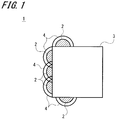
- FIG. 1 is a schematic configuration view of a first example of a catalyst according to a first embodiment of the present invention.
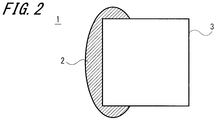
- FIG. 2 is a schematic block diagram of a second example of the catalyst according to the first embodiment of the present invention.
- FIG. 3 is a schematic configuration view of a third example of the catalyst according to the first embodiment of the present invention.
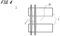
- FIG. 4 is a schematic configuration view of a fourth example of the catalyst according to the first embodiment of the present invention.
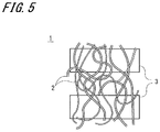
- FIG. 5 is a schematic configuration view of a fifth example of the catalyst according to the first embodiment of the present invention.
- FIG. 6 is a schematic configuration view of a sixth example of the catalyst according to the first embodiment of the present invention.
- FIG. 1 is a schematic configuration view of a first example of a catalyst according to a first embodiment of the present invention.
- FIG. 2 is a schematic block diagram of a second example of the catalyst according to the first embodiment of the present invention.
- FIG. 3 is a schematic configuration view of a third example of the catalyst according
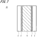
- FIG. 7 is a schematic configuration diagram of an example of a membrane electrode assembly according to a second embodiment of the present invention.
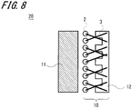
- FIG. 8 is a schematic configuration view of an example of a fuel cell member according to a third embodiment of the present invention.
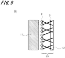
- FIG. 9 is a schematic block diagram of another example of the fuel cell member according to the third embodiment of the present invention.
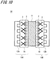
- FIG. 10 is a schematic configuration diagram of an example of a fuel cell according to a fourth embodiment of the present invention.
- FIG. 11 is a schematic configuration view for explaining a power generation mode of another example of the fuel cell according to the fourth embodiment of the present invention.
- FIG. 12 is a schematic configuration diagram of an example of a power storage device according to a fifth embodiment of the present invention.
- FIG. 13 is a diagram showing the power generation characteristics of the membrane electrode assembly in Example 1 and Comparative Example 1 of the present invention.
- FIG. 14 is a micrograph of the gas diffusion electrode (catalyst) in Example 4 of the present invention.
- FIG. 15 is a schematic block diagram of a main part of a conventional fuel cell.
- FIG. 16 is a schematic block diagram of a main part of a conventional fuel cell.
- the catalyst of the present embodiment is configured by providing a conductive region on at least a part of a substrate, and forming a carbon catalyst in the conductive region.
- This catalyst forms a carbon catalyst on the substrate to impart a catalytic function, and can significantly reduce the resistance with the substrate as compared with the case where the substrate is simply attached to and contacted with the substrate. It is possible.
- Such a carbon catalyst is easily formed by carbonization after depositing a carbon precursor polymer on a substrate.
- the shape of the carbon catalyst formed on the substrate can be variously modified depending on the material and structure of the substrate, the adhesion of the carbon precursor polymer to the substrate, and the like. For example, it has a point-like tip, a shape that exhibits a catalytic function at a point, and also coats the surface of the substrate to a certain extent, a shape that exhibits a catalytic function at that surface, and further bonds two or more positions on the substrate Various shapes, such as a shape, can be made. It may be any shape that transmits electrons to the substrate more efficiently than in the past.
- the substrate since the carbon precursor polymer is attached and then the carbonization treatment is performed, it is preferable that the substrate have heat resistance that can withstand the heat treatment in the carbonization step.
- the shape of the substrate is not particularly limited, and in the case of a structure which passes gas, that is, a shape having a gas diffusion function, it may be, for example, non-woven fabric, woven fabric, porous body, etc. Can also be used.
- conductive materials In addition to conductive materials, it is also possible to use materials of various shapes regardless of inorganic materials and organic materials as the substrate. Examples of the conductive material include carbon, metals and the like. In addition to ceramics, minerals (stones), etc., it is also possible to use inorganic or organic solid materials such as semiconductors such as silicon, and formed bodies of inorganic compounds such as carbides, nitrides and borides, powders, films, etc. The conductive region may be provided in part thereof.
- a gas diffusion function When a gas diffusion function is imparted as a catalyst and used as a gas diffusion electrode of a fuel cell, carbon cloth, carbon paper, carbon porous body, metal porous body generally used as a substrate serving as a gas diffusion electrode , Various cloths such as metal fibers, paper, etc. can be used. In addition, it may be a so-called nanofiber configuration fiberized by an electrospinning method or the like, or carbonized carbon nanofibers or a nonwoven fabric thereof.
- the carbon catalyst formed on the substrate desirably contains a nitrogen atom (N) and / or a boron atom (B). And it is preferable that the sum total of content of the nitrogen atom (N) and / or a boron atom (B) contained in a carbon catalyst is 0.5 mass% or more and 20 mass% or less with respect to the total weight of a carbon catalyst. Further, it is desirable that a carbon catalyst suitable for use in the catalyst of the present invention contains a nitrogen atom (N) and / or a boron atom (B), and further that a transition metal or transition metal compound is added.
- Such a carbon catalyst contains a nitrogen atom (N) and / or a boron atom (B), and further a transition metal or carbon precursor polymer to which a transition metal compound is added is applied to a substrate by a spray, a spinning method, etc. It can be made to adhere and then carbonize by heating etc.
- a carbon precursor polymer containing nitrogen atoms (N) and / or boron atoms (B) and further containing a transition metal or transition metal compound is subjected to a spinning method such as dry spinning, wet spinning, or electro spinning.
- a nanoshell structured carbon catalyst can be formed on the substrate by fiberizing and carbonizing the fiberized carbon precursor polymer.
- carbon particles (nanoshell carbon) having a nanoshell structure containing a high concentration of nitrogen atoms (N) are formed by the catalytic action of the transition metal or transition metal compound added to the carbon precursor polymer.
- the basic structure of nanoshell carbon is a structure in which carbon is chemically bonded by sp 2 hybrid orbital, and graphene which is an assembly of carbon atoms having a hexagonal network surface structure expanded in two dimensions is stacked.
- nitrogen atoms (N) are introduced into the hexagonal network surface structure in the carbonization process, pyridine type, pyrrole type, oxidized type, or graphene substitution type nitrogen atoms (N) are coordinated, and chemical bonds of different elements are caused. Defects in the induced graphene structure are said to exhibit catalytic activity.
- the excellent catalytic activity of this catalyst makes the particle size of nanoshell carbon 50 nm or less, more preferably 20 nm or less, more preferably 10 nm or less, and by making the shape into a fiber, the surface area is expanded and nitrogen on the surface of nanoshell carbon It is considered to be obtained by the presence of a high concentration of atoms (N).
- such miniaturization of the nanoshell structure is caused by the thickness of the graphene layer in nanoshell carbon being 10 nm or less, more preferably 5 nm or less.
- the thickness of the graphene layer is considered to improve the bending of the graphene and promote the formation of nanoshell carbon having a smaller particle size.
- nanoshell carbon used as a carbon catalyst of the catalyst of the present embodiment may exhibit a largely distorted structure such as many non-spherical oval, flat, and square shapes.
- the carbon catalyst used for the catalyst of the present invention may be other than carbon particles of nanoshell structure.
- a carbon precursor polymer is prepared.
- the carbon precursor polymer is not limited as long as it is a polymer material that can be carbonized by heat curing, but is not limited to polyacrylonitrile (PAN), chelate resin, cellulose, carboxymethylcellulose, polyvinyl alcohol, polyacrylic acid, polyfurfuryl Alcohol, furan resin, phenol resin, phenol formaldehyde resin, melamine resin, pitch, brown coal, polyvinylidene chloride, lignin, coal, biomass, protein, humic acid, polyimide, polyaniline, polyaniline, polypyrrole, polybenzimidazole, polyamide, polyamideimide, etc. It can be used.
- PAN polyacrylonitrile
- a carbon precursor polymer suitable for the present embodiment can be prepared by mixing or copolymerizing a polymer material that promotes crosslinking.
- a polymer material that promotes crosslinking For example, polyacrylonitrile-polymethacrylic acid copolymer (PAN-co-PMA) may be prepared and used by using a known soap-free polymerization method of acrylonitrile (AN) and methacrylate (MA).
- the carbon precursor polymer preferably has a nitrogen atom (N) as a constituent element.
- N nitrogen atom
- the content of nitrogen atoms (N) contained in the carbon precursor polymer is preferably 0.01% by mass or more and 30% by mass or less based on the total weight of the carbon catalyst. More preferably, it is 0.5% by mass or more and 20% by mass or less based on the total weight of the carbon catalyst.
- the PMA content is preferably 5 mol% or more and 15 mol% or less.
- the carbon precursor polymer prepared above and the transition metal or transition metal compound are dissolved in a solvent to prepare a solution.
- a solvent which can dissolve the carbon precursor polymer and which can be applied to a forming step of the carbon precursor polymer, for example, a fiberizing step is appropriately selected and used.
- the transition metal or transition metal compound is insoluble in the solvent, it is preferable to use a solvent with good dispersibility.
- a transition metal or transition metal compound is dissolved or dispersed in this solvent, and then the above-mentioned carbon precursor polymer is dissolved. Then, the carbon precursor polymer dissolved in the solvent and the transition metal or transition metal compound are kneaded to prepare a spinning solution.
- a spinning solution For example, when the above-mentioned PAN-co-PMA is used as the carbon precursor polymer and cobalt oxide is used as the transition metal compound, N, N-dimethylformamide (DMF), 2-pyrrolidone (NMP), or A homogeneous spinning solution can be produced by using at least one selected from dimethyl sulfoxide (DMSO).
- transition metal an element belonging to Group 4 to 12 of Period 4 of the periodic table can be used.
- cobalt (Co), iron (Fe), manganese (Mn), nickel (Ni), copper ( Cu), titanium (Ti), chromium (Cr) and zinc (Zn) are preferred.
- the transition metal compound salts, hydroxides, oxides, nitrides, sulfides, carbonized substances, complexes of the above-mentioned transition metals can be used, among which cobalt chloride, cobalt oxide, phthalocyanine cobalt, Iron chloride, iron oxide and phthalocyanine iron are preferred.
- Co, Fe, Mn, Ni, Cu, Ti, Cr, Zn and their compounds are excellent in forming a structure that improves the catalytic activity of the carbon catalyst, and among them, Co and Fe are particularly suitable for the catalytic activity. Excellent in forming a structure.
- the above-mentioned transition metal or transition metal compound can be produced by a known method, and for example, it can be produced by the method described in WO2007 / 049549 pamphlet and JP-A-2007-332436.
- the substrate is coated and applied using the above solution.
- a part of the gas diffusion electrode is coated.
- the coating method may be a general one, and may be dipping, spray coating, coater such as gravure, brush coating, coating method by resin extrusion, coating method by electrospinning, etc. on one side of the gas diffusion electrode, but is limited thereto It is not a thing.
- the coating thickness is preferably 0.01 ⁇ m or more and 2000 ⁇ m or less. This is because the catalyst thickness can be improved by setting the coating thickness in this range.
- the resin coating film can be made infusible.
- infusibilization the form of the applied resin can be maintained even at a temperature above the melting point or softening point of the carbon precursor polymer.
- the infusibilization is carried out by heating the carbon precursor polymer in air to a temperature below the melting point or softening point of the carbon precursor polymer to oxidize and crosslink the carbon precursor polymer.
- it can process by the well-known infusibilization method besides the above-mentioned method.
- the above-mentioned infusibilization treatment of PAN-co-PMA heats coated PAN-co-PMA from room temperature to 150 ° C. in air over 30 minutes, and then takes 2 hours from 150 ° C. to 220 ° C. The temperature is raised and maintained at 220.degree. C. for 3 hours.
- the infusible gas diffusion electrode is heated under a flow of an inert gas such as nitrogen and held for a fixed time to carbonize.
- the heating temperature is 300 ° C. to 1500 ° C., preferably 400 ° C. to 1000 ° C. This is because if the carbonization temperature is less than 300 ° C., carbonization of the carbon precursor polymer is insufficient, and if it exceeds 1500 ° C., the catalytic effect is reduced.
- the holding time of the heating temperature is 5 minutes or more and 180 minutes or less, preferably 20 minutes or more and 120 minutes or less. This is because if the holding time is less than 5 minutes, the gas diffusion electrode can not be heat-treated uniformly, and if the holding time exceeds 180 minutes, the catalyst performance is degraded.
- the carbon catalyst it is possible to improve catalyst activity by activating carbon dioxide (CO 2 ). Furthermore, the oxygen reduction activity of the carbon catalyst can be improved by introducing nitrogen atoms (N), boron atoms (B), and boron nitride (BN) into the carbon catalyst.
- N nitrogen atoms
- B boron atoms
- BN boron nitride
- the introduction of nitrogen atoms (N) into the carbon catalyst can be carried out using a liquid phase doping method, a gas phase doping method, or a gas phase-liquid phase doping method.
- a carbon catalyst is mixed with ammonia, which is a nitrogen source, melamine, acetonitrile or the like, and is 550 ° C. or more and 1200 ° C. or less under an inert gas atmosphere such as nitrogen (N 2 ), argon (Ar), helium (He) or the like
- Heat treatment can be carried out by holding for 5 minutes or more and 180 minutes or less to introduce nitrogen atoms (N) onto the surface of the carbon catalyst.
- the introduction of the boron atom (B) into the carbon catalyst can be carried out by mixing BF 3 methanol complex as a boron source with the nitrogen source when introducing the above-mentioned nitrogen atom (N).
- a method of contacting BCl 3 gas as a boron source with the carbon catalyst, or after mixing the carbon catalyst with BF 3 -methanol as a boron source Boron atoms to the carbon catalyst by a method of heat treatment under the conditions of 550 ° C to 1200 ° C and 5 minutes to 180 minutes in an inert gas atmosphere such as nitrogen (N 2 ), argon (Ar) and helium (He). (B) can be introduced.
- the transition metal or transition metal compound contained in the carbon catalyst is optionally removed by acid or electrolytic treatment.
- the catalyst 1 in which the carbon catalyst 2 is formed on the substrate 3 can be manufactured.
- the carbon catalyst 2 is coated with a binder 4 composed of a solid polymer electrolyte, an ionomer or the like.
- a binder 4 is provided on the carbon catalyst 2 formed on the substrate 3 and used as a gas diffusion electrode of a fuel cell, adhesion to a solid electrolyte can be enhanced.
- the carbon catalyst 2 is adhered in a block shape in close proximity to one side surface of the substrate 3, but the shapes of the substrate 3 and the carbon catalyst 2 are It is not limited to this.
- the carbon catalyst 2 may be integrally formed so as to cover one side of the base 3.
- the carbon catalyst 2 may be formed so as to extend across the gap 3S. May be.
- the carbon catalyst 2 may be formed so as to straddle the base 3 at a plurality of positions with respect to the base 3 configured to have the gap 3S.
- the position at which the carbon catalyst 2 is formed is not limited to the surface of the substrate 3 but may be the inside or both.
- the base 3 may be porous or fibrous, and the carbon catalyst 2 may be fibrously formed by a spinning method.
- a conductive filler 5 may be mixed with the carbon catalyst 2 formed on the substrate 3 in order to enhance the catalytic function.
- conductive substances such as carbon nanotubes, carbon nanofibers, carbon black, ketjen black, acetylene black, graphite, activated carbon, glassy carbon, carbon fiber, metal powder, metal fiber and the like can be used. . Alternatively, two or more of these conductive substances may be combined.
- a conductive material such as fiber, metal powder, metal fiber or the like may be mixed and coated on the substrate 3.
- the mixing ratio is desirably 85% by weight or less based on the carbon precursor solution.
- the above-described conductive substance may be dusted in a region including the position where the carbon catalyst 2 of the substrate 3 is to be formed in advance, and the above-mentioned carbon precursor solution may be coated thereon.
- a membrane electrode assembly can be obtained by providing a gas diffusion function to the base on which the carbon catalyst described in the first embodiment is formed to form a gas diffusion electrode and bonding it to at least one surface of a solid electrolyte. can get.
- a schematic diagram of this example is shown in FIG. The base 3 on which the carbon catalyst 2 is formed is bonded to both surfaces of the solid electrolyte 11 to constitute a membrane electrode assembly 20.
- a known material can be used as the material of the solid electrolyte, and any material having an ion exchange function such as a fluorine-based cation exchange resin membrane represented by a perfluorosulfonic acid resin membrane may be used.
- a bonding method a thermocompression bonding method can be used, and it may be in the range of temperature and holding time at which the substrate is not melted.
- the carbon catalyst 2 is bonded to the solid electrolyte relatively easily relatively easily by covering the binder 4 made of a solid polymer electrolyte, an ionomer or the like. It becomes possible. Bonding is easily performed by pressure bonding using a hot press machine or the like.
- FIG. 8 as a schematic block diagram of an example of the fuel cell member 10, a carbon catalyst 2 is formed, and a base 3 having a catalytic function at one end is prepared. Then, by solidifying a portion opposite to the side on which the carbon catalyst 2 is formed, for example, using a composite material composed of carbon and a resin, a separator function is added to the base in addition to the catalyst function, That is, it can be integrated with the separator 12. As described above, by integrating the base 3 on which the carbon catalyst 2 is formed with the separator 12, when the fuel cell is used, electrons generated by the catalyst are directly carried to the separator, so that a fuel cell with low resistance is configured. Has the advantage of being able to FIG.
- FIG. 8 shows an example in which asperities serving as gas flow paths are provided in the separator 12 and the surface of the base 3 opposite to the side on which the carbon catalyst 2 is formed is joined to the asperities. Further, by bonding the solid electrolyte 11 to the side on which the carbon catalyst 2 is formed, a part of the fuel cell is configured.
- FIG. 9 the other example which makes the separator 12 flat form is shown. In FIG. 9, parts corresponding to those in FIG. 8 are assigned the same reference numerals and redundant explanation will be omitted.
- the separator 12 is molded in advance.
- a material of the separator 12 for example, a material obtained by mixing a resin and a conductive filler can be used, and it can be produced by molding or the like.
- thermoplastic resin When a resin is used, a thermoplastic resin is preferable, and polypropylene, polystyrene, syndiotactic polystyrene, ABS resin (acrylonitrile, butadiene, styrene copolymer synthetic resin), polybutadiene, PPS (polyphenylene sulfide) resin, PEEK (polyether ether ketone)
- a thermoplastic resin that can withstand the power generation state of a fuel cell such as resin, fluorocarbon resin, fluorocarbon rubber, silicone rubber, EPDM (ethylene propylene) rubber, polycarbodiimide, and polyamide, can be preferably used.
- the resin, the conductive filler, or two or more of these materials are mixed.
- the conductive filler carbon black, ketjen black, acetylene black, carbon fiber, carbon nanofiber, carbon nanotube, graphite, glassy carbon, metal powder, metal fiber and the like can be used. These materials are mixed so that the weight ratio of resin to conductive filler (resin / conductive filler) is in the range of 5/95 to 75/25. Thereafter, the mixture is molded as a separator 12.
- the shape of the separator 12 may be any shape, and is not limited to the shape as shown in FIG. 8 in which the gas flow path is secured, the flat plate shape as shown in FIG.
- the separator made of this molded product is brought into close contact with the base 3 on which the carbon catalyst 2 described in the first embodiment is formed, that is, the gas diffusion electrode having a catalytic function, and heated to about the melting temperature of the resin. By doing this, both can be molded and integrated. Thereby, in addition to the target catalyst function and the gas diffusion function, the fuel cell member 10 having the separator function can be obtained.
- a solution constituting the separator 12 is produced in advance.
- a resin solution in which a conductive filler is dispersed can be used.
- a thermosetting resin or a thermoplastic resin can be used for the composition of the resin.
- any resin that can withstand the power generation state of the fuel cell may be used.
- the conductive filler carbon black, ketjen black, acetylene black, carbon fiber, carbon nanofiber, carbon nanotube, graphite, glassy carbon, metal powder, metal fiber, etc., or a mixture of two or more of these can be used.
- the resin and the conductive filler are mixed such that the weight ratio of resin / conductive filler is in the range of 5/95 to 75/25.
- the resin solution is applied to one side of the substrate 3 having a catalytic function on which the carbon catalyst 2 is formed, for example, a gas diffusion electrode, and dried and heat treated as necessary to impart a separator function.
- the member 10 is formed.
- the application method may be any existing method, and various methods such as dipping, brush coating, gravure using a coater, and a spray method are possible. According to this second manufacturing method, continuous production is possible, and extremely low cost can be achieved.
- the fuel cell 50 shown in FIG. 10 can be obtained by sandwiching the membrane electrode assembly shown in FIG. 7 described in the second embodiment with a separator.
- the gas diffusion electrodes 1A and 1B are joined with the side on which the carbon catalyst (not shown) is formed on both sides of the solid electrolyte 11 as the side in contact with the solid electrolyte 11, and further having gas flow paths from the outside.
- An example in which the fuel cell 50 is configured by sandwiching and integrating the shape separators 12A and 12B is shown.
- the gas diffusion electrode 1A or 1B and the separator 12A or 12B may be integrated to include the fuel cell members 10A and 10B, respectively.
- the catalyst comprising the above-described substrate having a gas diffusion function can be produced even in the form of a continuous sheet, the membrane electrode assembly and the fuel cell can also be produced continuously.
- a combination of a catalyst comprising a substrate having the gas diffusion layer function described above and an electrode using a catalyst such as platinum generally used on the counter electrode side may be used.
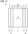
- FIG. 11 schematically shows a power generation mode of the fuel cell 50 according to an example of the present embodiment.
- a gas diffusion electrode 1A functioning as an anode electrode catalyst (fuel electrode) and a gas diffusion electrode 1B functioning as a cathode electrode catalyst (oxidant electrode) are joined so as to sandwich the solid electrolyte 11, and outside thereof
- the separators 12A and 12B are integrally configured.
- a fluorine-based cation exchange resin film represented by a perfluorosulfonic acid resin film is used as the solid electrolyte 11, as described above.
- This fuel cell can be integrated by sandwiching the both surfaces of the above-mentioned membrane electrode assembly with the separators 12A and 12B and bringing them into close contact by hot pressing or the like.
- a gas diffusion electrode made of a porous sheet (for example, carbon paper) also having a function as a current collector is interposed between a separator and an anode and a cathode catalyst.
- a carbon catalyst having a reduced contact resistance with the substrate is used as an anode electrode catalyst and a cathode electrode catalyst.
- the specific surface area is large, and high catalytic activity can be obtained.
- the separator 12A and 12B to support the gas diffusion electrode 1A and 1B an anode and a cathode electrode catalyst, to supply and discharge of the fuel gas H 2 and oxygen-containing gas reaction gas such as O 2. Then, when the reaction gas is supplied to the gas diffusion electrodes 1A and 1B, respectively, the gas phase (reaction gas) and the liquid phase (solid polymer electrolyte membrane) are generated at the boundary between the carbon catalyst provided on both electrodes and the solid electrolyte 11. And a solid phase (a catalyst possessed by both electrodes) are formed. Then, direct current power is generated by causing an electrochemical reaction.
- reaction gas reaction gas
- the liquid phase solid polymer electrolyte membrane
- FIG. 12 shows a schematic configuration diagram of an electric double layer capacitor 60 excellent in storage capacity as an example of the storage device of the present embodiment.
- the first electrode 61 and the second electrode 62 which are polarizable electrodes, face each other through the separator 63, and are accommodated in the exterior lid 64a and the exterior case 64b.
- the first electrode 61 and the second electrode 62 are connected to the exterior cover 64 a and the exterior case 64 b via the current collectors 65 respectively.
- the separator 63 is impregnated with an electrolytic solution. Then, in a state of being electrically insulated via the gasket 66, the outer cover 64a and the outer case 64b are crimped and sealed to constitute the electric double layer capacitor 60.
- the base on which the carbon catalyst described above is formed can be applied to the first electrode 61 and the second electrode 62.
- an electric double layer capacitor in which a carbon catalyst is applied to an electrode material can be constituted.
- the above-described carbon catalyst has a reduced contact resistance with the substrate, so that the electrode interface where charge is accumulated in the capacitor can be reliably held.
- the above-mentioned carbon catalyst is electrochemically inactive with respect to the electrolytic solution and has appropriate electrical conductivity. For this reason, the electrostatic capacitance per unit volume of an electrode can be improved by applying as an electrode of a capacitor.
- a substrate on which the above-described carbon catalyst is formed as an electrode material composed of a carbon material can be applied.
- the secondary battery with large electrical storage capacity can be comprised by the large specific surface area.
- the catalyst of the present invention is not limited to the above-mentioned example, but can be used as a substitute for environmental catalysts containing noble metals such as, for example, platinum.
- This example will be described below.
- a catalyst for exhaust gas purification to remove pollutants (mainly gaseous substances) contained in polluted air by decomposition treatment it is a catalyst material composed of a noble metal based material such as platinum singly or in combination.
- Environmental catalysts are used.
- a substitute for an exhaust gas purification catalyst containing a noble metal such as platinum a substrate on which the above-described carbon catalyst is formed can be used.
- the above-mentioned carbon catalyst is made into a nanoshell structure, since the catalytic action is further improved, it has a function of decomposing a substance to be treated such as a contaminant. For this reason, since it is not necessary to use expensive noble metals, such as platinum, by comprising an environmental catalyst using the above-mentioned catalyst, a low cost environmental catalyst can be provided.
- the carbon catalyst has a nanoshell structure, the large specific surface area makes it possible to enlarge the treated area per unit volume for decomposition of the substance to be treated, and an environmental catalyst excellent in the decomposition function per unit volume. It can be configured.
- the above-mentioned carbon catalyst as a carrier and supporting noble metal materials such as platinum used in conventional environmental catalysts alone or in the form of a complex, an environment having an excellent catalytic function such as decomposition function.
- a catalyst can be constructed.
- the environmental catalyst provided with the above-mentioned carbon catalyst can also be used not only as the above-mentioned exhaust gas purification catalyst but also as a purification catalyst for water treatment.
- the catalyst of the present invention can be used as a substitute for various other platinum catalysts. That is, it can be used as various catalysts other than the above-mentioned environmental catalyst as a substitute of the general process catalyst for the chemical industry containing noble metals, such as platinum.
- This catalyst can provide a low cost chemical reaction process catalyst without using expensive noble metals such as platinum.
- the chemical reaction process catalyst excellent in the chemical reaction efficiency per unit volume can be comprised by a large specific surface area.
- Such a carbon catalyst for chemical reaction is applied to, for example, a catalyst for hydrogenation reaction, a catalyst for dehydrogenation reaction, a catalyst for oxidation reaction, a catalyst for polymerization reaction, a catalyst for reforming reaction, a catalyst for steam reforming, etc. be able to. More specifically, it is possible to apply the above-mentioned catalyst to each chemical reaction with reference to the literature on catalysts such as "Catalyst preparation (Kodansha) Takasaki Shirasaki, Todo Naoyuki co-author, 1975".
- Example 1 Preparation of gas diffusion electrode having catalytic function
- 30.93 g of acrylonitrile manufactured by Wako Pure Chemical Industries, Ltd.
- 4.07 g of methacrylic acid manufactured by Wako Pure Chemical Industries, Ltd.
- 300 ml of pure water are charged, and bubbling is performed for 15 minutes with nitrogen gas.
- the flask was set in an oil bath and adjusted to 70 ° C.
- the coated gas diffusion electrode was then set in a forced circulation dryer. Then, in an air atmosphere, the temperature was raised from room temperature to 150 ° C. for 30 minutes, and then from 150 ° C. to 220 ° C. in two hours. Thereafter, it was kept at 220 ° C. for 3 hours to make it infusible.
- the infusibilized gas diffusion electrode was placed in a baking furnace, purged with nitrogen for 20 minutes, and heated from room temperature to 900 ° C. over 1.5 hours. After this, the temperature was maintained at 900 ° C. for 1 hour, the carbonization treatment was performed, and a gas diffusion electrode having a carbon catalyst formed was produced.
- MEA membrane electrode assembly
- This spinning solution is electrospun under the conditions of an applied voltage of 25 to 28 kV, a discharge pressure of 3 to 7 kPa, a bore diameter of 0.31 mm in the discharge tip, and a distance between the nozzle and the collector of 0.15 to 0.20 m, Obtained.
- the nanofiber nonwoven fabric infusibilized by the above method was placed in a quartz tube, purged with nitrogen gas for 20 minutes in an ellipsoidal reflection infrared gold image furnace, and heated from room temperature to 900 ° C. over 1.5 hours . Thereafter, the nanofiber non-woven fabric was subjected to carbonization treatment while maintaining at 900 ° C. for 1 hour.
- Electrode layer Preparation of catalyst dispersion
- a catalyst dispersion was obtained.
- the solid polymer membrane was sandwiched between the respective gas diffusion electrodes, and was pressure-bonded for 10 minutes at 150 ° C. using a hot press, to produce an MEA (membrane electrode assembly).
- MEA membrane electrode assembly
- a power generation test was conducted by passing 200 ml / min of hydrogen on the anode side and 200 ml / min of oxygen on the cathode side at a heating temperature of 80 ° C. As a result, a result of an open circuit voltage of 0.74 V and a voltage of 0.17 V at a current density of 0.5 A / cm 2 was obtained.
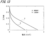
- Example 1 The results of the power generation performance characteristics in Example 1 and Comparative Example 1 are shown in FIG. As is clear from FIG. 13, in Example 1, a relatively high voltage is obtained at a lower current density than in Comparative Example 1, and it is clear that the power generation performance is improved.
- Example 2 As a second embodiment, an example of a fuel cell member in which a carbon catalyst is formed on a substrate having a gas diffusion function and a separator function is further provided will be described.
- Separator Solution 100 ml of methanol (manufactured by Wako Pure Chemical Industries, Ltd.) was mixed with 10 g of a phenol resin (manufactured by Gunei Chemical Industry Co., Ltd.) to prepare a mixed solution. 5 g of ketjen black EC600JD (trade name, manufactured by Lion Corporation) was added to this solution to obtain a carbon / resin mixed solution.
- the solid polymer film was sandwiched between the gas diffusion electrodes, and was pressure bonded for 10 minutes at 150 ° C. using a hot press.
- a power generation test was conducted by passing 200 ml / min of hydrogen on the anode side and 200 ml / min of oxygen on the cathode side at a heating temperature of 80 ° C. As a result, a result of an open circuit voltage of 0.78 V and a voltage of 0.36 V at a current density of 0.5 A / cm 2 was obtained.
- Example 3 Preparation of polyacrylonitrile-polymethacrylic acid copolymer (PAN-co-PMA)]
- PAN-co-PMA polyacrylonitrile-polymethacrylic acid copolymer
- This spinning solution was used as a carbon paper (Toray Industries, Ltd.) as a gas diffusion electrode under the conditions of an applied voltage of 25 to 28 kV, a discharge pressure of 3 to 7 kPa, a bore diameter of 0.31 mm in the discharge tip, and a distance between the nozzle and the collector of 0.15 to 0.20 m. Electrospinning was performed on one side of 2.3 ⁇ 2.3 cm 2 by a trade name of TGP-H-060 (trade name, manufactured by Co., Ltd.) and coated.
- the gas diffusion electrode infusibilized by the above method was placed in a baking furnace, purged with nitrogen for 20 minutes, and heated from room temperature to 900 ° C. over 1.5 hours. After this, the temperature was maintained at 900 ° C. for 1 hour, and carbonization treatment was performed to produce a gas diffusion electrode having a catalytic function.
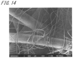
- a photomicrograph of the obtained gas diffusion electrode having a catalytic function is shown in FIG.
- the substrate has a slightly thick fiber shape and has a gas diffusion function
- the carbon catalyst has a thinner fiber shape and has a structure entwined on the substrate, and is strongly bonded. You can see how it is being done.
- the solid polymer membrane was sandwiched between the respective gas diffusion electrodes, and was pressure-bonded for 10 minutes at 150 ° C. using a hot press, to produce an MEA (membrane electrode assembly).
- MEA membrane electrode assembly
- a power generation test was conducted by passing 200 ml / min of hydrogen on the anode side and 200 ml / min of oxygen on the cathode side at a heating temperature of 80 ° C. As a result, a result of an open circuit voltage of 0.80 V and a voltage of 0.36 V at a current density of 0.5 A / cm 2 was obtained.
- Example 4 [Preparation of gas diffusion electrode having catalytic function]
- 30.93 g of acrylonitrile manufactured by Wako Pure Chemical Industries, Ltd.
- 4.07 g of methacrylic acid manufactured by Wako Pure Chemical Industries, Ltd.
- 300 ml of pure water are charged, and bubbling is performed for 15 minutes with nitrogen gas.
- the flask was set in an oil bath and adjusted to 70 ° C.
- a solution of 100 mg of potassium peroxodisulfate (manufactured by Wako Pure Chemical Industries, Ltd.) dissolved in 50 ml of pure water was charged into a flask adjusted to 70 ° C.
- the coated gas diffusion electrode was then set in a forced circulation dryer. Then, in an air atmosphere, the temperature was raised from room temperature to 150 ° C. for 30 minutes, and then from 150 ° C. to 220 ° C. in two hours. Thereafter, it was kept at 220 ° C. for 3 hours to make it infusible.
- the infusibilized gas diffusion electrode was placed in a baking furnace, purged with nitrogen for 20 minutes, and heated from room temperature to 900 ° C. over 1.5 hours. After this, the temperature was maintained at 900 ° C. for 1 hour, and carbonization treatment was performed to fabricate a gas diffusion electrode on which a carbon catalyst was formed.
- the solid polymer membrane was sandwiched between the respective gas diffusion electrodes, and was pressure-bonded for 10 minutes at 150 ° C. using a hot press, to produce an MEA (membrane electrode assembly).
- MEA membrane electrode assembly
- a power generation test was conducted by passing 200 ml / min of hydrogen on the anode side and 200 ml / min of oxygen on the cathode side at a heating temperature of 80 ° C. As a result, a result of an open circuit voltage of 0.78 V and a voltage of 0.35 V at a current density of 0.5 A / cm 2 was obtained.
- Example 5 [Preparation of gas diffusion electrode] [Preparation of polyacrylonitrile-polymethacrylic acid copolymer (PAN-co-PMA)]
- PAN-co-PMA polyacrylonitrile-polymethacrylic acid copolymer
- This resin was sufficiently dispersed in 94 g of dimethylformamide (manufactured by Wako Pure Chemical Industries, Ltd.), and then 5.82 g of the above-mentioned PAN-co-PMA was dissolved to obtain a spinning solution.
- This spinning solution is electrospun under the conditions of an applied voltage of 25 to 28 kV, a discharge pressure of 3 to 7 kPa, a bore diameter of 0.31 mm in the discharge tip, and a distance between the nozzle and the collector of 0.15 to 0.20 m, Obtained.
- the four sides of the nanofiber nonwoven fabric obtained by the above-described method were clipped and set in a forced circulation dryer. Then, the temperature was raised from room temperature to 150 ° C. in the air for 30 minutes, and then from 150 ° C. to 220 ° C. in two hours. Thereafter, the nanofiber non-woven fabric was made infusible by maintaining it at 220 ° C. for 3 hours as it was.
- the nanofiber nonwoven fabric infusibilized by the method described above was placed in a calcining furnace, purged with argon gas for 20 minutes, and heated from room temperature to 2950 ° C. over 12 hours. After this, the temperature was maintained at 2950 ° C. for 1 hour to prepare a nanofiber non-woven gas diffusion electrode.
- the solid polymer membrane was sandwiched between the respective gas diffusion electrodes, and was pressure-bonded for 10 minutes at 150 ° C. using a hot press, to produce an MEA (membrane electrode assembly).
- MEA membrane electrode assembly
- a power generation test was conducted by passing 200 ml / min of hydrogen on the anode side and 200 ml / min of oxygen on the cathode side at a heating temperature of 80 ° C. As a result, a result of an open circuit voltage of 0.80 V and a voltage of 0.36 V at a current density of 0.5 A / cm 2 was obtained.
Landscapes
- Chemical & Material Sciences (AREA)
- Chemical Kinetics & Catalysis (AREA)
- Electrochemistry (AREA)
- General Chemical & Material Sciences (AREA)
- Engineering & Computer Science (AREA)
- Manufacturing & Machinery (AREA)
- Materials Engineering (AREA)
- Physics & Mathematics (AREA)
- Thermal Sciences (AREA)
- Fuel Cell (AREA)
- Inert Electrodes (AREA)
- Catalysts (AREA)
Abstract
本発明は、触媒と、この触媒と組み合わせる他の部材とを一体化して部品点数の削減を図るとともに、その接触抵抗を低減化することを目的、課題とする。 上記課題は、基体3の少なくとも一部に導電性領域を設け、この導電性領域に炭素触媒2が形成されてなる構成とすることにより、解決される。 そして、上記構成は、炭素前駆体高分子を基体に付着させ、炭素化することにより形成される。
Description
本発明は、白金や白金合金等の貴金属を担持しない炭素触媒を用いた触媒及びその製造方法、膜電極接合体及びその製造方法、燃料電池部材及びその製造方法、燃料電池及び蓄電装置に関する。
高効率、無公害の燃料電池の実用化は、地球温暖化、環境汚染問題に対する重要な解決策の一つとして注目されている。燃料電池は、水素などの燃料と酸素などの酸化剤を供給して電力を取り出す化学電池の一種で、例えば水の電気分解の逆反応、すなわち
2H2+O2→2H2O
を利用して電力を取り出すものが主流となっている。
燃料電池は、このような電気化学反応や電解質等の種類によって幾つかのタイプに分けられる。燃料電池の種類としては、固体高分子型燃料電池、アルカリ電解質型燃料電池、リン酸型燃料電池、固体酸化物型燃料電池、及びバイオ燃料電池等が挙げられる。これらのうち、特に固体高分子型燃料電池は室温動作が可能であり、また小型軽量化が容易であることから、携帯機器や燃料電池自動車等への応用が期待されている。
2H2+O2→2H2O
を利用して電力を取り出すものが主流となっている。
燃料電池は、このような電気化学反応や電解質等の種類によって幾つかのタイプに分けられる。燃料電池の種類としては、固体高分子型燃料電池、アルカリ電解質型燃料電池、リン酸型燃料電池、固体酸化物型燃料電池、及びバイオ燃料電池等が挙げられる。これらのうち、特に固体高分子型燃料電池は室温動作が可能であり、また小型軽量化が容易であることから、携帯機器や燃料電池自動車等への応用が期待されている。
固体高分子型燃料電池の基本構造は、燃料極(負極)、固体高分子膜(電解質)、空気極(正極)を貼り合わせて一体化した膜電極接合体(Membrane Electrode Assembly:MEA)と呼ばれる基本部品を、反応ガスの供給流路が形成された導電板で挟みこんで1つの基本単位を構成し、これを単セルとする。この単セルを積層して直列接続し高電圧を得られるようにしている。積層する場合は、導電板がセパレータの機能を有する。
水のイオン化等の反応性を高めるため、現在では負極及び正極としてガス拡散電極が設けられ、また固体電解質側に白金や白金化合物等の触媒を担持したカーボンが用いられている。したがって、固体高分子型燃料電池の構成は、固体電解質を挟んで触媒層、ガス拡散電極、セパレータが接合される構造となる(例えば特許文献1~3参照)。
特許文献1~3に記載されている従来の一般的な燃料電池は、図15に示すように、固体電解質111と、白金等の触媒金属を担持する炭素粒子等の触媒層102、ガス拡散電極103、更にセパレータ106とが配置されて構成される。図示しないが固体電解質111の他の面にも同様に触媒金属を担持する触媒、ガス拡散電極、セパレータがこの順に配置される。
このような燃料電池の製造方法としては以下の工程がとられる。まず、固体電解質膜上に、白金などの電極触媒を担持させた炭素粒子より成る触媒と、固体電解質溶液(触媒を接着するバインダーとしても働く)とを混合して形成されたスラリーを作製する。その後、このスラリーを固体電解質111に塗布し、乾燥させる。一方、組み合わせるガス拡散電極103と前述した触媒層102を塗布した固体電解質111を貼り合わせ、ホットプレスにより、図15中白抜き矢印P1及びP2で示すように、両側から圧着して、各部材を接合する。ガス拡散電極103としては、カーボンクロス、カーボンペーパー、金属発泡体、金属繊維ペーパーなどが用いられる。このとき、ガス拡散電極103には、発電時に発生する水を効率よく排出するために、フッ素樹脂などで撥水加工したものが用いられる。
上述したように、従来の燃料電池においては、触媒層とガス拡散電極、またガス拡散電極とセパレータとの界面は、接触、圧着などで形成されており、接触抵抗が高い。この様子を図16に示す。図16においては、カーボンファイバー、カーボンペーパー等より成るガス拡散電極103の一方の面に、白金等の触媒(図示せず)を担持した炭素粒子より成る触媒層102が付着される。触媒層102の各炭素粒子の表面や炭素粒子間の空間には、固体高分子電解質等のバインダー104が形成されていてもよい。この場合、図示しないが炭素粒子表面に担持される白金等の触媒により反応が促進されて水素がイオン化されて電子が分離するが、この電子は触媒層102の各炭素粒子を通じてガス拡散電極103に流れる。この場合、触媒とガス拡散電極とは、圧着しているとはいえ、バインダー104成分を含んで触媒層102がガス拡散電極103で点接触しているに過ぎない。したがってこの部分の接触抵抗が無視できず、すなわち燃料電池で発電した電子は、点接触による抵抗によってロスが生じている。このようなロスは、燃料電池の発電特性に影響を及ぼす。また、部品点数も多く、コスト高を招来し、生産性が悪いなどの問題点を有している。
例えば上記特許文献3に開示の燃料電池では、固体電解質と触媒及びガス拡散電極をバインダーにより一体化しているが、電気的には物質同士の接触による導電経路が形成されているのみであって、根本的な問題解決に至っていない。
つまり、従来の燃料電池においては、発電に必要な電子の伝導は、触媒層/ガス拡散電極/セパレータの物質間の伝導性が十分でなく、接触抵抗により大きく損失している。
つまり、従来の燃料電池においては、発電に必要な電子の伝導は、触媒層/ガス拡散電極/セパレータの物質間の伝導性が十分でなく、接触抵抗により大きく損失している。
以上の問題に鑑みて、本発明は、触媒と、この触媒を保持し、他の部材と組み合わせる基体とを一体化して部品点数の削減を図ると共に、その接触抵抗を低減化することを目的とする。
また、本発明は、この触媒を用いて燃料電池の部品、又は燃料電池を構成することによって、触媒と電極との電気伝導性を改善することを目的とする。
また、本発明は、この触媒を用いて燃料電池の部品、又は燃料電池を構成することによって、触媒と電極との電気伝導性を改善することを目的とする。
上記課題を解決するため、本発明の触媒は、基体の少なくとも一部に導電性領域が設けられ、この導電性領域に炭素触媒が形成されて成る構成とする。
炭素触媒は、広く化学反応用の触媒として使用することができ、特に、従来の白金触媒の代替として使用することができる。このように、基体の少なくとも一部に導電性領域を設け、ここに炭素触媒を形成することによって、炭素触媒と基体との接触抵抗が低減される。
そして、基体を導電性材料より構成する場合は、触媒機能を有する電極として用いることが可能となる。
また、炭素触媒を形成する基体として、気体を通過させる構造を少なくとも一部に有する材料を用いる場合は、燃料電池用の触媒機能付ガス拡散電極として好適に用いることが可能であり、その場合は燃料電池における電気伝導性の改善を図ることができる。
炭素触媒は、広く化学反応用の触媒として使用することができ、特に、従来の白金触媒の代替として使用することができる。このように、基体の少なくとも一部に導電性領域を設け、ここに炭素触媒を形成することによって、炭素触媒と基体との接触抵抗が低減される。
そして、基体を導電性材料より構成する場合は、触媒機能を有する電極として用いることが可能となる。
また、炭素触媒を形成する基体として、気体を通過させる構造を少なくとも一部に有する材料を用いる場合は、燃料電池用の触媒機能付ガス拡散電極として好適に用いることが可能であり、その場合は燃料電池における電気伝導性の改善を図ることができる。
また、本発明の触媒の製造方法は、炭素前駆体高分子を調製する工程と、炭素前駆体高分子を、基体の導電性領域に付着させる工程と、炭素前駆体高分子を炭素化する工程と、を含む。
このように、炭素前駆体高分子を調製して基体の少なくとも導電性領域に付着させ、この炭素前駆体高分子を炭素化することによって、基体に容易に炭素触媒を形成することができる。このとき、基体の形状によっては、基体の表面だけでなく、基体の内部の空孔等に炭素触媒を形成してもよい。そして、このように形成された炭素触媒は、基体に対して単に接触しているだけではなく、基体の材料及び炭素化の条件によって、物理的な結合、或いは化学的な結合によって、基体と比較的強固に結びつく。したがって、従来に比べて接触抵抗を低減化することができる。
このように、炭素前駆体高分子を調製して基体の少なくとも導電性領域に付着させ、この炭素前駆体高分子を炭素化することによって、基体に容易に炭素触媒を形成することができる。このとき、基体の形状によっては、基体の表面だけでなく、基体の内部の空孔等に炭素触媒を形成してもよい。そして、このように形成された炭素触媒は、基体に対して単に接触しているだけではなく、基体の材料及び炭素化の条件によって、物理的な結合、或いは化学的な結合によって、基体と比較的強固に結びつく。したがって、従来に比べて接触抵抗を低減化することができる。
本発明の膜電極接合体(MEA)は、固体電解質と、固体電解質を挟んで対向配置されたガス拡散電極と、を備える。そしてガス拡散電極は、その少なくとも一部に、炭素触媒が形成されて成る。
また、本発明の膜電極接合体の製造方法は、炭素前駆体高分子を調製する工程と、炭素前駆体高分子を、ガス拡散電極の少なくとも一部に付着させる工程と、炭素前駆体高分子を炭素化する工程と、固体電解質と、炭素触媒が形成されたガス拡散電極とを一体化する工程と、を含む。
本発明の燃料電池部材は、基体の少なくとも一部に炭素触媒が形成されて成るガス拡散電極と、セパレータとが、一体に形成されて成る。
また、本発明の燃料電池部材の製造方法は、炭素前駆体高分子を調製する工程と、炭素前駆体高分子を、ガス拡散電極を構成する基体の少なくとも一部に付着させる工程と、炭素前駆体高分子を炭素化して炭素触媒を形成する工程と、炭素触媒が形成されている部分の少なくとも一部を残して、基体をセパレータと一体化する工程と、を含む。
本発明の燃料電池は、固体電解質と、固体電解質を挟んで対向配置されたガス拡散電極と、を備え、ガス拡散電極は、固体電解質を挟む側に、炭素触媒が形成されて成る。
本発明の蓄電装置は、電極材と電解質とを備えた蓄電装置において、電極材が、炭素触媒を備える。
上述したように、本発明の膜電極接合体、燃料電池部材、燃料電池及び蓄電装置は、基体の少なくとも一部に炭素触媒が形成され、或いは電極材に炭素触媒が形成されるので、部品点数の削減を図ることができる。燃料電池に用いる場合は、ガス拡散電極を構成する基体と触媒との接触抵抗が改善される。したがって、ガス拡散電極と触媒との接触部分における電気伝導性を改善することができ、発電特性が改善された燃料電池を提供することができる。
また、構成部品点数を少なくすることができ、良好な生産性、低コスト化をもたらす。更に、ガス拡散電極自体が触媒機能をもつこととなり、触媒で発生した電子を接触抵抗のロスを生じることなく伝導することができる。これにより、燃料電池の発電効率の向上を図ることが可能となる。
さらに、触媒機能を有するガス拡散電極をセパレータと一体化することによって、触媒で発生した電子を、接触抵抗のロスを発生することなく、セパレータまで伝えることが可能となる。よって、非常に効率の高い、燃料電池を作製することができる。
また、構成部品点数を少なくすることができ、良好な生産性、低コスト化をもたらす。更に、ガス拡散電極自体が触媒機能をもつこととなり、触媒で発生した電子を接触抵抗のロスを生じることなく伝導することができる。これにより、燃料電池の発電効率の向上を図ることが可能となる。
さらに、触媒機能を有するガス拡散電極をセパレータと一体化することによって、触媒で発生した電子を、接触抵抗のロスを発生することなく、セパレータまで伝えることが可能となる。よって、非常に効率の高い、燃料電池を作製することができる。
また、上述の膜電極接合体の製造方法、燃料電池部材の製造方法によれば、炭素触媒をガス拡散電極に容易に形成することができ、触媒とガス拡散電極との接触抵抗の低減化による電気伝導性の改善、発電特性の向上に加え、生産性の向上を図ることが可能となる。
本発明によれば、触媒と、この触媒と組み合わせる他の部材との接触抵抗を低減化することが可能となる。
また、本発明の触媒を用いて燃料電池の部品や燃料電池、又は蓄電装置を構成することによって、触媒と電極との電気伝導性を改善することができる。
また、本発明の触媒を用いて燃料電池の部品や燃料電池、又は蓄電装置を構成することによって、触媒と電極との電気伝導性を改善することができる。
以下、本発明の具体的な実施の形態について詳細に説明する。本発明の実施の形態の説明を以下の順序で行う。
〔1〕第1の実施の形態(触媒とその製造方法)
〔2〕第2の実施の形態(膜電極接合体とその製造方法)
〔3〕第3の実施の形態(燃料電池部材とその製造方法)
〔4〕第4の実施の形態(燃料電池)
〔5〕第5の実施の形態(蓄電装置)
〔1〕第1の実施の形態(触媒とその製造方法)
〔2〕第2の実施の形態(膜電極接合体とその製造方法)
〔3〕第3の実施の形態(燃料電池部材とその製造方法)
〔4〕第4の実施の形態(燃料電池)
〔5〕第5の実施の形態(蓄電装置)
〔1〕第1の実施の形態(触媒とその製造方法)
本実施の形態の触媒は、基体の少なくとも一部に導電性領域を設け、この導電性領域に炭素触媒が形成されて構成される。この触媒は、基体に炭素触媒を形成して触媒機能を付与するものであり、基体との間の抵抗を、単に基体に付着させて接触している場合と比べ、格段に低減化することが可能である。このような炭素触媒は、基体に炭素前駆体高分子を付着した後、炭素化することによって、容易に形成される。
本実施の形態の触媒は、基体の少なくとも一部に導電性領域を設け、この導電性領域に炭素触媒が形成されて構成される。この触媒は、基体に炭素触媒を形成して触媒機能を付与するものであり、基体との間の抵抗を、単に基体に付着させて接触している場合と比べ、格段に低減化することが可能である。このような炭素触媒は、基体に炭素前駆体高分子を付着した後、炭素化することによって、容易に形成される。
基体に形成される炭素触媒の形状は、基体の材料や構造、炭素前駆体高分子の基体への付着態様等によって、様々に変形することができる。例えば点状の先端を有し、触媒機能を点で発現する形状、また、ある程度基体の表面をコートし、その表面で触媒機能を発現する形状、更に、基体上の2以上の位置を結合する形状等、種々の形状とすることができる。従来と比べてより効率的に基体に電子を伝える形状であればよい。
基体の材料としては、炭素前駆体高分子を付着した後炭素化処理を行うことから、炭素化工程での熱処理に耐えられる程度の耐熱性を有することが望ましい。
基体の形状は特に限定されるものではなく、気体(ガス)を通過する構造、すなわちガス拡散機能を有する形状とする場合は、例えば不織布、織布、多孔質体などでもよく、また、成型物も用いることができる。
基体の形状は特に限定されるものではなく、気体(ガス)を通過する構造、すなわちガス拡散機能を有する形状とする場合は、例えば不織布、織布、多孔質体などでもよく、また、成型物も用いることができる。
なお、基体として導電性材料の他、無機材料、有機材料を問わず種々の形状の材料を用いることも可能である。導電性の材料としては、カーボン、金属等が挙げられる。また、セラミック、鉱物(石)、等の他、シリコンのような半導体や炭化物、窒化物、ホウ化物などの無機化合物の成形体、粉末、膜など無機又は有機の固体材料を用いることも可能であり、その一部に導電性領域が設けられればよい。
触媒としてガス拡散機能を付与し、燃料電池のガス拡散電極として用いる場合は、ガス拡散電極となる基体として、一般的に用いられているカーボンクロス、カーボンペーパー、カーボン多孔質体、金属多孔質体、金属繊維を用いたクロス、ペーパーなどさまざまなものを用いることができる。また、電界紡糸法などにより繊維化したいわゆるナノファイバー構成としてもよく、炭素化したカーボンナノファイバーやその不織布でもよい。
また、基体に形成する炭素触媒は、窒素原子(N)及び/又はホウ素原子(B)を含有することが望ましい。そして炭素触媒に含まれる窒素原子(N)及び/又はホウ素原子(B)の含有量の合計が、炭素触媒の全重量に対し0.5質量%以上20質量%以下であることが好ましい。
また本発明の触媒に用いて好適な炭素触媒は、窒素原子(N)及び/又はホウ素原子(B)を含むとともに、更に遷移金属又は遷移金属化合物が添加されることが望ましい。このような炭素触媒は、窒素原子(N)及び/又はホウ素原子(B)を含み、更に遷移金属又は遷移金属化合物が添加された炭素前駆体高分子を、基体に塗布、スプレー、紡糸方法等により付着させ、その後加熱等により炭化して作製することができる。
また本発明の触媒に用いて好適な炭素触媒は、窒素原子(N)及び/又はホウ素原子(B)を含むとともに、更に遷移金属又は遷移金属化合物が添加されることが望ましい。このような炭素触媒は、窒素原子(N)及び/又はホウ素原子(B)を含み、更に遷移金属又は遷移金属化合物が添加された炭素前駆体高分子を、基体に塗布、スプレー、紡糸方法等により付着させ、その後加熱等により炭化して作製することができる。
なお、窒素原子(N)及び/又はホウ素原子(B)を含み、更に遷移金属又は遷移金属化合物が添加された炭素前駆体高分子を、乾式紡糸、湿式紡糸、又は、電界紡糸等の紡糸方法により繊維化し、繊維化された炭素前駆体高分子を炭素化することにより、ナノシェル構造の炭素触媒を基体に形成することができる。この場合、炭素前駆体高分子に添加されている遷移金属又は遷移金属化合物の触媒作用等により、窒素原子(N)を高濃度に含有したナノシェル構造の炭素粒子(ナノシェル炭素)が形成される。
ナノシェル構造の炭素粒子を用いる場合は、より高い触媒活性を示す。この要因として以下のことが考えられる。ナノシェル炭素の基本構造は、炭素がsp2混成軌道により化学結合し、二次元に広がった六角網面構造を持つ炭素原子の集合体であるグラフェンが積層した構造である。炭素化過程で窒素原子(N)が六角網面構造に導入されると、ピリジン型、ピロール型、酸化型、又はグラフェン置換型の窒素原子(N)が配位し、異元素の化学結合により誘起されたグラフェン構造の欠陥が触媒活性を示す、とされている。この触媒における優れた触媒活性は、ナノシェル炭素の粒径を50nm以下、より好ましくは20nm以下、更に好ましくは10nm以下とし、形状を繊維状とすることで表面積を広げ、更にナノシェル炭素の表面に窒素原子(N)を高濃度に存在させることによって得られると考えられる。
また、このようなナノシェル構造の微細化は、ナノシェル炭素におけるグラフェン層の厚みが10nm以下、より好ましくは5nm以下で形成していることが要因と考えられる。このグラフェン層の厚さがグラフェンの屈曲を良くし、より小さな粒径のナノシェル炭素の形成を促していると考えられる。加えて、このような屈曲性ゆえに、本実施の形態の触媒の炭素触媒として用いるナノシェル炭素は、球状以外の多くの楕円、扁平、角型など、大きく歪んだ構造を示すことがある。
なお、本発明の触媒に用いる炭素触媒は、ナノシェル構造の炭素粒子以外のものでもよい。
次に、本実施の形態の触媒の製造方法の一例について説明する。
まず、炭素前駆体高分子を調製する。炭素前駆体高分子としては、熱硬化によって炭素化可能な高分子材料であれば限定するものではないが、ポリアクリロニトリル(PAN)、キレート樹脂、セルロース、カルボキシメチルセルロース、ポリビニルアルコール、ポリアクリル酸、ポリフルフリルアルコール、フラン樹脂、フェノール樹脂、フェノールホルムアルデヒド樹脂、メラミン樹脂、ピッチ、褐炭、ポリ塩化ビニリデン、リグニン、石炭、バイオマス、タンパク質、フミン酸、ポリイミド、ポリアニリン、ポリピロール、ポリベンゾイミダゾール、ポリアミド、ポリアミドイミドなどを用いることができる。
まず、炭素前駆体高分子を調製する。炭素前駆体高分子としては、熱硬化によって炭素化可能な高分子材料であれば限定するものではないが、ポリアクリロニトリル(PAN)、キレート樹脂、セルロース、カルボキシメチルセルロース、ポリビニルアルコール、ポリアクリル酸、ポリフルフリルアルコール、フラン樹脂、フェノール樹脂、フェノールホルムアルデヒド樹脂、メラミン樹脂、ピッチ、褐炭、ポリ塩化ビニリデン、リグニン、石炭、バイオマス、タンパク質、フミン酸、ポリイミド、ポリアニリン、ポリピロール、ポリベンゾイミダゾール、ポリアミド、ポリアミドイミドなどを用いることができる。
また、炭素化に不適な高分子材料であっても、架橋を促す高分子材料を混合又は共重合させることにより、本実施の形態に適した炭素前駆体高分子を調製することができる。例えば、アクリロニトリル(AN)とメタクリレート(MA)とを公知のソープフリー重合法を用いてポリアクリロニトリル-ポリメタクリル酸共重合体(PAN-co-PMA)を調製して用いてもよい。
炭素前駆体高分子としては、構成元素に窒素原子(N)を有していることが好ましい。特に、ポリアクリロニトリル(PAN)のように構成元素に窒素原子(N)を高濃度に有することが好ましい。炭素前駆体高分子に含まれる窒素原子(N)の含有量は、炭素触媒の全重量に対し0.01質量%以上30質量%以下であることが好ましい。さらに好ましくは炭素触媒の全重量に対し、0.5質量%以上20質量%以下である。
また、例えば、上述したポリアクリロニトリル-ポリメタクリル酸共重合体(PAN-co-PMA)では、PMA含有量が15mol%を超えると、不融化する際に融着が起き炭素化した際に形体が保持できない。また、PAN含有量が多くPMA含有量が少ない方が、炭素触媒に含まれる窒素原子(N)の量が多くなり、炭素触媒の酸素還元活性能力を向上させることができると考えられる。しかし、PMA含有量が5mol%未満の炭素前駆体高分子から製造した炭素触媒は、酸素還元活性を表す酸素還元ボルタモグラムの還元電流が低下する。従って、PAN-co-PMAを用いる場合、PMA含有量は、5mol%以上15mol%以下であることが好ましい。
次に、上記調製した炭素前駆体高分子と、遷移金属又は遷移金属化合物とを、溶媒に溶解して、溶液を作製する。溶媒は、炭素前駆体高分子を溶解でき、炭素前駆体高分子の成型工程、例えば繊維化工程に適用できるものを適宜選択して用いる。遷移金属又は遷移金属化合物が溶媒に不溶である場合は、分散性の良い溶媒を用いることが好ましい。
この溶媒に、遷移金属又は遷移金属化合物を溶解又は分散させた後、上述の炭素前駆体高分子を溶解させる。そして、溶媒に溶解した炭素前駆体高分子と、遷移金属又は遷移金属化合物とを混練することにより、紡糸溶液を作製する。
例えば、炭素前駆体高分子として上述のPAN-co-PMAを用い、遷移金属化合物として酸化コバルトを用いる場合には、溶媒としてN,N-ジメチルホルムアミド(DMF)、2-ピロリドン(NMP)、又は、ジメチルスルホキシド(DMSO)から選ばれる少なくとも一種を用いることにより、均一な紡糸溶液を作製することができる。
例えば、炭素前駆体高分子として上述のPAN-co-PMAを用い、遷移金属化合物として酸化コバルトを用いる場合には、溶媒としてN,N-ジメチルホルムアミド(DMF)、2-ピロリドン(NMP)、又は、ジメチルスルホキシド(DMSO)から選ばれる少なくとも一種を用いることにより、均一な紡糸溶液を作製することができる。
遷移金属としては、周期表の3族から12族の第4周期に属する元素を用いることができ、例えば、コバルト(Co)、鉄(Fe)、マンガン(Mn)、ニッケル(Ni)、銅(Cu)、チタン(Ti)、クロム(Cr)、亜鉛(Zn)が好ましい。
また、遷移金属化合物としては、上記遷移金属の塩、水酸化物、酸化物、窒化物、硫化物、炭素化物、錯体を用いることができ、このうち特に、塩化コバルト、酸化コバルト、フタロシアニンコバルト、塩化鉄、酸化鉄、フタロシアニン鉄が好ましい。
また、遷移金属化合物としては、上記遷移金属の塩、水酸化物、酸化物、窒化物、硫化物、炭素化物、錯体を用いることができ、このうち特に、塩化コバルト、酸化コバルト、フタロシアニンコバルト、塩化鉄、酸化鉄、フタロシアニン鉄が好ましい。
Co,Fe,Mn,Ni,Cu,Ti,Cr,Zn及びその化合物は、炭素触媒の触媒活性を向上させる構造を形成することに優れ、その中でも特に、Co及びFeは、触媒活性に好適な構造を形成することに優れる。
なお、上記遷移金属又は遷移金属化合物は、公知の方法により製造できるが、例えば、国際公開第2007/049549号パンフレット、特開2007-332436号公報に記載の方法で製造することがあげられる。
次に、上記溶液を用いて、基体の少なくとも一部にコート、塗布する。基体を導電性材料とし、ガス拡散機能を有するガス拡散電極とする場合は、ガス拡散電極の一部にコートする。コート方法は一般的なものでよく、ガス拡散電極の片面にディッピング、スプレー塗布、グラビアなどのコーター、はけ塗り、樹脂押出しによるコート方法、電界紡糸によるコート方法などが挙げられるが、これらに限るものではない。塗布厚みは、0.01μm以上2000μm以下が望ましい。これは、塗布厚みをこの範囲とすることによって、触媒活性を良好にすることができることによる。
次に、炭素前駆体として熱硬化性に乏しい高分子材料を用いる場合、樹脂塗布膜の不融化を行うことができる。不融化することにより、炭素前駆体高分子の融点又は軟化点以上の温度であっても、塗布樹脂の形態を維持することができる。
不融化は、空気中において炭素前駆体高分子の融点又は軟化点以下の温度に加熱し、炭素前駆体高分子を酸化して架橋させることによって行なう。また、上述の方法以外にも、公知の不融化方法により処理することができる。これにより、後の炭素化工程において、炭素前駆体高分子を熱処理する際に、高分子の溶融による形状の崩壊や、樹脂同士の融着を防止することができる。
不融化は、空気中において炭素前駆体高分子の融点又は軟化点以下の温度に加熱し、炭素前駆体高分子を酸化して架橋させることによって行なう。また、上述の方法以外にも、公知の不融化方法により処理することができる。これにより、後の炭素化工程において、炭素前駆体高分子を熱処理する際に、高分子の溶融による形状の崩壊や、樹脂同士の融着を防止することができる。
例えば、上述のPAN-co-PMAの不融化処理は、コートしたPAN-co-PMAを、空気中において室温から150℃まで30分かけて昇温した後、150℃~220℃まで2時間かけて昇温し、220℃でそのまま3時間保持することにより行う。
次に、不融化したガス拡散電極を、窒素等の不活性ガス流通下で加熱し、一定時間保持して炭素化する。この加熱温度としては、300℃以上1500℃以下、好ましくは400℃以上1000℃以下とする。これは、炭素化温度が300℃未満であると、炭素前駆体高分子の炭素化が不十分であり、また、1500℃を超えると、触媒効果が減少するからである。また、上記加熱温度の保持時間は、5分以上180分以下、好ましくは、20分以上120分以下とする。これは、保持時間が5分未満では、ガス拡散電極を均一に熱処理することができず、保持時間が180分を超えると、触媒性能の低下が起きるためである。
また、上述の炭素触媒において、二酸化炭素(CO2)を賦活することにより、触媒活性を向上させることが可能である。
更に、炭素触媒中に窒素原子(N)、ホウ素原子(B)、窒化ホウ素(BN)が導入されることにより、炭素触媒の酸素還元活性を向上させることができる。
更に、炭素触媒中に窒素原子(N)、ホウ素原子(B)、窒化ホウ素(BN)が導入されることにより、炭素触媒の酸素還元活性を向上させることができる。
炭素触媒への窒素原子(N)の導入は、液相ドープ法、気相ドープ法、または、気相-液相ドープ法を用いて行うことができる。例えば、炭素触媒に、窒素源であるアンモニア、メラミン、アセトニトリル等を混合し、窒素(N2)、アルゴン(Ar)、ヘリウム(He)等の不活性ガス雰囲気下で550℃以上1200℃以下、5分以上180分以下保持することにより熱処理して炭素触媒の表面に窒素原子(N)を導入することができる。
また、炭素触媒へのホウ素原子(B)の導入は、上述の窒素原子(N)を導入する際にホウ素源であるBF3メタノール錯体等を窒素源と共に混合することにより行うことができる。また、炭素触媒に上述の方法で窒素原子(N)を導入した後、ホウ素源としてBCl3ガスを炭素触媒に接触させる方法や、炭素触媒をホウ素源であるBF3-メタノールに混合した後、窒素(N2)、アルゴン(Ar)、ヘリウム(He)等の不活性ガス雰囲気下で550℃以上1200℃以下、5分以上180分以下保持する条件で熱処理する方法により、炭素触媒へホウ素原子(B)を導入することができる。
次に、炭素触媒中に含まれている遷移金属又は遷移金属化合物を、必要に応じて酸または電解処理して除去する。
以上の処理によって、図1に示すように、基体3に炭素触媒2が形成された触媒1を作製することができる。なお、図1に示す例においては、炭素触媒2が固体高分子電解質やアイオノマー等より成るバインダー4に被覆されている例を示す。このようなバインダー4を基体3に形成した炭素触媒2に被覆して設ける場合は、燃料電池のガス拡散電極として用いる場合に、固体電解質への密着性を高めることができる。
なお、図1に示す第1の例においては、基体3の一方の側面に、炭素触媒2が塊状となって近接して被着される例を示すが、基体3や炭素触媒2の形状はこれに限定されるものではない。
例えば、図2に第2の例を示すように、基体3の一方の側面を覆って一体的に炭素触媒2が形成されていてもよい。
例えば、図2に第2の例を示すように、基体3の一方の側面を覆って一体的に炭素触媒2が形成されていてもよい。
また、図3に第3の例を示すように、基体3の表面から内部にかけて、気体を通過させる間隙3Sがある構成でもよく、この間隙3Sに跨るように炭素触媒2が形成されている形状でもよい。
更に、図4に第4の例を示すように、間隙3Sを有する構成の基体3に対して、炭素触媒2が複数の位置で基体3に跨る形状で形成されていてもよい。この場合、炭素触媒2が形成される位置は基体3の表面に限定されず、内部であってもよく、その両方であってもよい。
また例えば、図5に第5の例を示すように、基体3が多孔質体や繊維状とされ、紡糸法により炭素触媒2が繊維状に形成されて成る構成でもよい。
更に、図4に第4の例を示すように、間隙3Sを有する構成の基体3に対して、炭素触媒2が複数の位置で基体3に跨る形状で形成されていてもよい。この場合、炭素触媒2が形成される位置は基体3の表面に限定されず、内部であってもよく、その両方であってもよい。
また例えば、図5に第5の例を示すように、基体3が多孔質体や繊維状とされ、紡糸法により炭素触媒2が繊維状に形成されて成る構成でもよい。
更に、図6に第6の例を示すように、触媒機能をより高めるために、基体3に形成した炭素触媒2に、導電性フィラー5を混合してもよい。導電性フィラー5としては、カーボンナノチューブ、カーボンナノファイバー、カーボンブラック、ケッチェンブラック、アセチレンブラック、黒鉛、活性炭、ガラス状カーボン、炭素繊維、金属粉末、金属ファイバーなどの導電性物質を用いることができる。或いは、これら導電性物質のうち、二種類以上を組み合わせてもよい。
炭素触媒2への導電性フィラー5の混合方法としては、前述の炭素前駆体溶液中に、カーボンナノチューブ、カーボンナノファイバー、カーボンブラック、ケッチェンブラック、アセチレンブラック、黒鉛、活性炭、ガラス状カーボン、炭素繊維、金属粉末、金属ファイバーなどの導電性物質を混合し、基体3にコートすればよい。混合割合は、炭素前駆体溶液に対し、85重量%以下とすることが望ましい。85重量%以上になると、炭素前駆体溶液の流動性が極端に悪くなり、コートしにくくなるためである。また、コートする前に、あらかじめ基体3の炭素触媒2を形成しようとする位置を含む領域に、上記した導電性物質をまぶし、その上から前述の炭素前駆体溶液をコートしてもよい。
〔2〕第2の実施の形態(膜電極構造体とその製造方法)
第1の実施の形態において説明した炭素触媒が形成された基体にガス拡散機能を付与してガス拡散電極とし、固体電解質の少なくとも一方の面に接合することによって、膜電極構造体(MEA)が得られる。この一例の概略構成図を図7に示す。炭素触媒2が形成された基体3が、固体電解質11の両面に接合されて膜電極構造体20が構成される。
第1の実施の形態において説明した炭素触媒が形成された基体にガス拡散機能を付与してガス拡散電極とし、固体電解質の少なくとも一方の面に接合することによって、膜電極構造体(MEA)が得られる。この一例の概略構成図を図7に示す。炭素触媒2が形成された基体3が、固体電解質11の両面に接合されて膜電極構造体20が構成される。
固体電解質の材料としては、既知の材料を用いることができ、パーフルオロスルホン酸樹脂膜を代表とするフッ素系陽イオン交換樹脂膜等の、イオン交換機能を有する材料であればよい。
接合方法としては、加熱圧着方法を用いることができ、基体を溶融しない温度及び保持時間の範囲であればよい。
またこのとき、前述の図1において説明したように、炭素触媒2に固体高分子電解質やアイオノマー等より成るバインダー4を被覆しておくことによって、比較的容易に、固体電解質に対し強固に接合することが可能となる。接合は、ホットプレス機等を用いた圧着により容易に行われる。
接合方法としては、加熱圧着方法を用いることができ、基体を溶融しない温度及び保持時間の範囲であればよい。
またこのとき、前述の図1において説明したように、炭素触媒2に固体高分子電解質やアイオノマー等より成るバインダー4を被覆しておくことによって、比較的容易に、固体電解質に対し強固に接合することが可能となる。接合は、ホットプレス機等を用いた圧着により容易に行われる。
〔3〕第3の実施の形態(燃料電池部材とその製造方法)
第1の実施の形態において説明した炭素触媒が形成された基体にガス拡散機能を付与してガス拡散電極とし、固体電解質に接合する前の段階として、セパレータに接合する、或いはセパレータ機能を付与することによって、燃料電池部材を構成することが可能である。この燃料電池部材を予め製造しておき、固体電解質を挟んで接合することによって、簡単な工程で燃料電池を製造することが可能となる。
第1の実施の形態において説明した炭素触媒が形成された基体にガス拡散機能を付与してガス拡散電極とし、固体電解質に接合する前の段階として、セパレータに接合する、或いはセパレータ機能を付与することによって、燃料電池部材を構成することが可能である。この燃料電池部材を予め製造しておき、固体電解質を挟んで接合することによって、簡単な工程で燃料電池を製造することが可能となる。
例えば、図8に燃料電池部材10の一例の概略構成図を示すように、炭素触媒2が形成され、触媒機能を一端に有する基体3を用意する。そしてその炭素触媒2が形成される側とは反対側の部分を、例えばカーボンと樹脂とより構成される複合材料を用いて固化することによって、基体に触媒機能に加えてセパレータ機能を付加し、すなわちセパレータ12と一体化することができる。このように、炭素触媒2を形成した基体3をセパレータ12と一体化することによって、燃料電池に用いる場合において、触媒で発生した電子が直接セパレータまで運ばれるため、抵抗の少ない燃料電池を構成することが可能となるという利点を有する。
図8においては、セパレータ12にガス流路となる凹凸を設け、凹凸面に基体3の炭素触媒2が形成されている側とは反対側の面が接合されている例を示す。また、炭素触媒2が形成される側に固体電解質11を接合することで、燃料電池の一部が構成される。
図9においては、セパレータ12を平板状とする他の例を示す。図9において、図8と対応する部分には同一符号を付して重複説明を省略する。
図8においては、セパレータ12にガス流路となる凹凸を設け、凹凸面に基体3の炭素触媒2が形成されている側とは反対側の面が接合されている例を示す。また、炭素触媒2が形成される側に固体電解質11を接合することで、燃料電池の一部が構成される。
図9においては、セパレータ12を平板状とする他の例を示す。図9において、図8と対応する部分には同一符号を付して重複説明を省略する。
このような本実施の形態に係る燃料電池部材の製造方法の例を以下説明する。
[1]第1の作製方法
あらかじめセパレータ12を成型する。セパレータ12の材料としては、例えば樹脂と導電性フィラー等を混合した材料を用いることができ、成型等により作製できる。樹脂を用いる場合は熱可塑性樹脂が好ましく、ポリプロピレン、ポリスチレン、シンジオタクチック-ポリスチレン、ABS樹脂(アクリロニトリル、ブタジエン、スチレン共重合合成樹脂)、ポリブタジエン、PPS(ポリフェニレンサルファイド)樹脂、PEEK(ポリエーテルエーテルケトン)樹脂、フッ素樹脂、フッ素ゴム、シリコンゴム、EPDM(エチレンプロピレン)ゴム、ポリカルボジイミド、ポリアミドなど、燃料電池の発電状態に耐えられる、熱可塑性樹脂であれば好ましく用いることができる。
この樹脂と、導電性フィラーと、或いはこれらの二種以上の材料を混合する。導電性フィラーとしては、カーボンブラック、ケッチェンブラック、アセチレンブラック、カーボンファイバー、カーボンナノファイバー、カーボンナノチューブ、黒鉛、ガラス状カーボン、金属粉末、金属繊維などを用いることができる。これらの材料を、樹脂と導電性フィラーとの重量割合比(樹脂/導電性フィラー)が5/95から75/25の範囲となるように混合する。その後、この混合物をセパレータ12として成型する。セパレータ12の形状はどのような形でもよく、図8に示すようなガス流路を確保した形状、図9に示す平板形状などに限定されず、その他の形状とすることができる。この成型物より成るセパレータと、前述の第1の実施の形態において説明した炭素触媒2が形成された基体3、すなわち触媒機能を有するガス拡散電極とを密着させて、樹脂の溶融温度付近まで加熱することにより、両者を成型し、一体化することができる。これにより、目的とする触媒機能とガス拡散機能に加えて、セパレータ機能を有する燃料電池部材10を得ることができる。
[2]第2の作製方法
あらかじめ、セパレータ12を構成する溶液を作製する。溶液としては、導電性フィラーを分散した樹脂溶液を用いることができる。樹脂の組成は、熱硬化性樹脂あるいは熱可塑性樹脂が使用できる。たとえばポリプロピレン、ポリスチレン、シンジオタクチック-ポリスチレン、ABS樹脂、ポリブタジエン、PPS樹脂、PEEK樹脂、フッ素樹脂、フッ素ゴム、シリコンゴム、EPDMゴム、ポリカルボジイミド、ポリアミド、フェノール樹脂、エポキシ樹脂、メラミン樹脂、ポリエステル樹脂など、燃料電池の発電状態に耐えられる、樹脂であればよい。
あらかじめ、セパレータ12を構成する溶液を作製する。溶液としては、導電性フィラーを分散した樹脂溶液を用いることができる。樹脂の組成は、熱硬化性樹脂あるいは熱可塑性樹脂が使用できる。たとえばポリプロピレン、ポリスチレン、シンジオタクチック-ポリスチレン、ABS樹脂、ポリブタジエン、PPS樹脂、PEEK樹脂、フッ素樹脂、フッ素ゴム、シリコンゴム、EPDMゴム、ポリカルボジイミド、ポリアミド、フェノール樹脂、エポキシ樹脂、メラミン樹脂、ポリエステル樹脂など、燃料電池の発電状態に耐えられる、樹脂であればよい。
導電性フィラーは、カーボンブラック、ケッチェンブラック、アセチレンブラック、カーボンファイバー、カーボンナノファイバー、カーボンナノチューブ、黒鉛、ガラス状カーボン、金属粉末、金属繊維など、あるいはこれらの二種類以上の混合物を使用できる。これら樹脂と導電性フィラーとを、樹脂/導電性フィラーの重量割合比が5/95から75/25の範囲となるように混合する。そしてこの樹脂溶液を、前述した炭素触媒2が形成された触媒機能を有する基体3、例えばガス拡散電極の片面に塗布し、必要に応じて乾燥、熱処理することでセパレータ機能を付与し、燃料電池部材10を形成する。塗布方法は、既存のいずれの方法でもよく、ディッピング、刷毛塗り、グラビアなどコーターを用いる方法、スプレー法など様々な方法が可能である。
この第2の作製方法による場合は、連続的生産が可能であり、極端な低コスト化が可能になる。
この第2の作製方法による場合は、連続的生産が可能であり、極端な低コスト化が可能になる。
〔4〕第4の実施の形態(燃料電池)
次に、上述のガス拡散機能を有する基体より成る触媒を、アノード電極及び/又はカソード電極に適用した燃料電池について説明する。
第2の実施の形態において説明した図7に示す膜電極接合体をセパレータで挟むことによって、図10に示す燃料電池50を得ることができる。この例においては、固体電解質11の両側に炭素触媒(図示せず)が形成される側を固体電解質11と接する側としてガス拡散電極1A及び1Bが接合され、更にその外側からガス流路を有する形状のセパレータ12A及び12Bで挟み込み、一体化して燃料電池50を構成する例を示す。この場合、ガス拡散電極1A又は1Bとセパレータ12A又は12Bが一体化されて、それぞれ燃料電池部材10A及び10Bを含む構成としてもよい。
また、上述のガス拡散機能を有する基体より成る触媒は、連続したシート状でも作製可能であるため、膜電極接合体および燃料電池を連続で作製することもできる。
また、上述のガス拡散層機能を有する基体より成る触媒と、対極側に一般的に用いられている白金などの触媒を使用した電極との組み合わせでもよい。
図11に、本実施の形態の一例の燃料電池50における発電態様を模式的に示す。燃料電池50は、固体電解質11を挟むように、アノード電極触媒(燃料極)として機能するガス拡散電極1A、カソード電極触媒(酸化剤極)として機能するガス拡散電極1Bが接合され、その外側にセパレータ12A及び12Bが一体化されて構成される。
固体電解質11としては、上述したようにパーフルオロスルホン酸樹脂膜を代表とするフッ素系陽イオン交換樹脂膜が用いられる。
この燃料電池は、前述の膜電極接合体の両面をセパレータ12A及び12Bで挟み、ホットプレス等により密着させることにより、一体化することができる。
固体電解質11としては、上述したようにパーフルオロスルホン酸樹脂膜を代表とするフッ素系陽イオン交換樹脂膜が用いられる。
この燃料電池は、前述の膜電極接合体の両面をセパレータ12A及び12Bで挟み、ホットプレス等により密着させることにより、一体化することができる。
従来の燃料電池では、集電体としての機能も有する多孔質のシート(例えば、カーボンペーパー)からなるガス拡散電極を、セパレータとアノード及びカソード電極触媒との間に介在させていた。
これに対して、本発明の実施の形態による燃料電池では、基体との接触抵抗を低減した炭素触媒をアノード電極触媒及びカソード電極触媒として用いるものである。特に、炭素触媒をナノシェル構造とするときは比表面積が大きく、高い触媒活性が得られる。このような構成とすることにより、部品点数の削減、製造コストの低減化を図ることができると共に、炭素触媒と基体すなわちガス拡散電極との接触抵抗を低減化できるので、電気伝導性を改善し、良好な発電特性を得ることが可能となる。
これに対して、本発明の実施の形態による燃料電池では、基体との接触抵抗を低減した炭素触媒をアノード電極触媒及びカソード電極触媒として用いるものである。特に、炭素触媒をナノシェル構造とするときは比表面積が大きく、高い触媒活性が得られる。このような構成とすることにより、部品点数の削減、製造コストの低減化を図ることができると共に、炭素触媒と基体すなわちガス拡散電極との接触抵抗を低減化できるので、電気伝導性を改善し、良好な発電特性を得ることが可能となる。
上記セパレータ12A及び12Bは、アノード及びカソード電極触媒であるガス拡散電極1A及び1Bを支持すると共に、燃料ガスH2や酸化剤ガスO2等の反応ガスの供給・排出を行う。そして、ガス拡散電極1A及び1Bにそれぞれ反応ガスが供給されると、両電極に備えられた炭素触媒と固体電解質11との境界において、気相(反応ガス)、液相(固体高分子電解質膜)、固相(両電極が持つ触媒)の三相界面が形成される。そして、電気化学反応を生じさせることで直流電力が発生する。
上記電気化学反応において、
カソード側(ガス拡散電極1B):O2+4H++4e-→2H2O
アノード側(ガス拡散電極1A):H2→2H++2e-
の反応が起こり、アノード側で生成されたH+イオンは固体電解質11中をカソード側に向かって移動し、e-(電子)は外部の負荷を通ってカソード側に移動する。
一方、カソード側では酸化剤ガス中に含まれる酸素と、アノード側から移動してきたH+イオン及びe-とが反応して水が生成される。この結果、上述の燃料電池は、水素と酸素とから直流電力を発生し、水を生成することになる。
上記電気化学反応において、
カソード側(ガス拡散電極1B):O2+4H++4e-→2H2O
アノード側(ガス拡散電極1A):H2→2H++2e-
の反応が起こり、アノード側で生成されたH+イオンは固体電解質11中をカソード側に向かって移動し、e-(電子)は外部の負荷を通ってカソード側に移動する。
一方、カソード側では酸化剤ガス中に含まれる酸素と、アノード側から移動してきたH+イオン及びe-とが反応して水が生成される。この結果、上述の燃料電池は、水素と酸素とから直流電力を発生し、水を生成することになる。
〔5〕第5の実施の形態(蓄電装置)
次に、上述の触媒を電極材に適用した蓄電装置について説明する。
図12に本実施の形態の蓄電装置の一例として、蓄電容量に優れた電気二重層キャパシタ60の概略構成図を示す。
図12に示す電気二重層キャパシタ60は、セパレータ63を介して、分極性電極である第1の電極61及び第2の電極62が対向し、外装蓋64aと外装ケース64bの中に収容されている。また、第1の電極61及び第2の電極62は、それぞれ集電体65を介して、外装蓋64aと外装ケース64bに接続されている。また、セパレータ63には、電解液が含浸されている。そして、ガスケット66を介して電気的に絶縁させた状態で、外装蓋64aと外装ケース64bとをかしめて密封させて電気二重層キャパシタ60が構成される。
上記の本実施の形態の電気二重層キャパシタ60において、上述の炭素触媒が形成された基体を第1の電極61及び第2の電極62に適用することができる。そして、電極材に炭素触媒が適用された電気二重層キャパシタを構成することができる。
上述の炭素触媒は、基体との間の接触抵抗が低減化されているので、キャパシタにおいて電荷が蓄積する電極界面を確実に保持することができる。さらに、上述の炭素触媒は、電解液に対して電気化学的に不活性であり、適度な電気導電性を有する。このため、キャパシタの電極として適用することにより、電極の単位体積あたりの静電容量を向上させることができる。
上述の炭素触媒は、基体との間の接触抵抗が低減化されているので、キャパシタにおいて電荷が蓄積する電極界面を確実に保持することができる。さらに、上述の炭素触媒は、電解液に対して電気化学的に不活性であり、適度な電気導電性を有する。このため、キャパシタの電極として適用することにより、電極の単位体積あたりの静電容量を向上させることができる。
また、上述のキャパシタと同様に、例えば、リチウムイオン二次電池の負極材等のように、炭素材料から構成される電極材として上述の炭素触媒が形成された基体を適用することができる。そして、炭素触媒を前述したようにナノシェル構造とするときは、その比表面積が大きいことにより、蓄電容量の大きな二次電池を構成することができる。
本発明の触媒は、上述の例に限定されることなく、例えば白金等の貴金属を含む環境触媒の代替品として使用することも可能である。以下この例について説明する。
汚染空気に含まれる汚染物質を(主にガス状物質)等を分解処理により除去するための排ガス浄化用触媒として、白金等の貴金属系の材料が単独又は複合化物されて構成された触媒材料による環境触媒が用いられている。
これらの白金等の貴金属を含む排ガス浄化用触媒の代替品として、上述の炭素触媒が形成された基体を使用することができる。上述の炭素触媒をナノシェル構造とする場合は、触媒作用がより向上しているため、汚染物質等の被処理物質の分解機能を有する。
このため、上述の触媒を用いて環境触媒を構成することにより、白金等の高価な貴金属類を使用する必要がないため、低コストの環境触媒を提供することができる。また、炭素触媒をナノシェル構造とするときは、比表面積が大きいことにより、単位体積あたりの被処理物質を分解する処理面積を大きくすることができ、単位体積あたりの分解機能が優れた環境触媒を構成できる。
なお、上述の炭素触媒を担体として、従来の環境触媒に使用されている白金等の貴金属系の材料を単独に、又は複合化物として担持させることにより、より分解機能等の触媒作用に優れた環境触媒を構成することができる。
なお、上述の炭素触媒を備える環境触媒は、上述の排ガス浄化用触媒だけでなく、水処理用の浄化触媒として用いることもできる。
また、本発明の触媒は、その他の種々の白金触媒の代替品として使用することができる。つまり、白金等の貴金属を含む化学工業用の一般的なプロセス触媒の代替品として、上述の環境触媒以外の各種触媒として使用可能である。この触媒によれば、白金等の高価な貴金属類を使用することなく、低コストの化学反応プロセス触媒を提供することができる。さらに、炭素触媒をナノシェル構造とするときは、比表面積が大きいことにより、単位体積あたりの化学反応効率に優れた化学反応プロセス触媒を構成することができる。
このような化学反応用の炭素触媒は、例えば、水素化反応用触媒、脱水素反応用触媒、酸化反応用触媒、重合反応用触媒、改質反応用触媒、水蒸気改質用触媒等に適用することができる。更に具体的には、「触媒調製(講談社)白崎高保、藤堂尚之共著、1975年」等の触媒に関する文献を参照し、各々の化学反応に上述の触媒を適用することが可能である。
このような化学反応用の炭素触媒は、例えば、水素化反応用触媒、脱水素反応用触媒、酸化反応用触媒、重合反応用触媒、改質反応用触媒、水蒸気改質用触媒等に適用することができる。更に具体的には、「触媒調製(講談社)白崎高保、藤堂尚之共著、1975年」等の触媒に関する文献を参照し、各々の化学反応に上述の触媒を適用することが可能である。
次に、実施例により本発明を具体的に説明するが、本発明は、下記の実施例に限定されるものではない。
(実施例1)
〔触媒機能を有するガス拡散電極の調製〕
四つ口フラスコにアクリロニトリル(和光純薬工業(株)製)30.93g、メタクリル酸(和光純薬工業(株)製)4.07g、純水300mlを入れ、窒素ガスにより15分間バブリングを行った。次に、オイルバスにフラスコをセットし、70℃に調整した。そして、ペルオキソ二硫酸カリウム(和光純薬工業(株)製)100mgを純水50mlに溶解した溶液を70℃に調整したフラスコ内に投入し、窒素ガス雰囲気中で撹拌しながら4時間重合させた。この後放冷し、乳白色液の溶液を得た。
次に、乳白色液の溶液を濃縮後、濃縮液を60℃で真空乾燥し、約20gのポリアクリロニトリル-ポリメタクリル酸共重合体(PAN-co-PMA)を得た。
酸化コバルト(シーアイ化成(株)製、NanoTek(登録商標)、平均粒径2nm)0.18gをジメチルホルムアミド(和光純薬工業(株)製)94gに十分に分散させた後、上述のPAN-co-PMA5.82gを溶解し溶液を得た。このとき全固形分に対する酸化コバルトは3質量%であり、溶液全量に対する全固形分は6質量%であった。
ガス拡散電極として、カーボンペーパー(東レ(株)製、商品名TGP-H-060)2.3×2.3cm2を用い、この片面に上記樹脂溶液をスプレー法によりコートした。
ガス拡散電極として、カーボンペーパー(東レ(株)製、商品名TGP-H-060)2.3×2.3cm2を用い、この片面に上記樹脂溶液をスプレー法によりコートした。
〔不融化処理〕
その後、コートしたガス拡散電極を、強制循環式乾燥機内にセットした。そして、空気雰囲気下で、30分間で室温から150℃まで昇温し、続いて2時間かけて150℃から220℃まで昇温した。その後、220℃でそのまま3時間保持し、不融化を行った。
その後、コートしたガス拡散電極を、強制循環式乾燥機内にセットした。そして、空気雰囲気下で、30分間で室温から150℃まで昇温し、続いて2時間かけて150℃から220℃まで昇温した。その後、220℃でそのまま3時間保持し、不融化を行った。
〔炭素化処理〕
まず、不融化処理したガス拡散電極を焼成炉に入れ、20分間窒素パージし、1.5時間かけて室温から900℃まで昇温した。この後、900℃で1時間保持し、炭素化処理を行い、炭素触媒が形成されたガス拡散電極を作製した。
まず、不融化処理したガス拡散電極を焼成炉に入れ、20分間窒素パージし、1.5時間かけて室温から900℃まで昇温した。この後、900℃で1時間保持し、炭素化処理を行い、炭素触媒が形成されたガス拡散電極を作製した。
〔発電性能特性〕
得られた、炭素触媒が形成されたガス拡散電極の触媒面に、5%Nafion(登録商標)分散液(アルドリッチ社製)700μLを、印刷機を用いて塗布した。その後、強制循環乾燥機中110℃で3時間乾燥しカソード電極とした。次に、アノード側に白金を担持したアノード電極(東レ(株)製、商品名TGP-H-060)2.3×2.3cm2を、また固体電解質膜として、Nafion(登録商標)112(デュポン社製、商品名)を準備した。そして、固体高分子膜を各ガス拡散電極で挟み、ホットプレス機を使い150℃、10分間圧着させ、MEA(膜電極接合体)を作製した。
上記の方法で作製したMEAを用いて、加温80℃でアノード側には水素を200ml/min、カソード側には酸素を200ml/minで流し発電試験を行った。その結果、開回路電圧0.79V、電流密度0.5A/cm2時の電圧0.35Vの結果が得られた。
(比較例1)
〔ポリアクリロニトリル-ポリメタクリル酸共重合体(PAN-co-PMA)の調製〕
四つ口フラスコにアクリロニトリル(和光純薬工業(株)製)30.93g、メタクリル酸(和光純薬工業(株)製)4.07g、純水300mlを入れ、窒素ガスにより15分間バブリングを行なった。次に、オイルバスにフラスコをセットし、70℃に調整した。そして、ペルオキソ二硫酸カリウム(和光純薬工業(株)製)100mgを純水50mlに溶解した溶液を70℃に調整したフラスコ内に投入し、窒素ガス雰囲気中で攪拌しながら4時間重合させた。この後、放冷し、乳白色液の溶液を得た。
次に、乳白色の溶液を濃縮後、濃縮液を60℃で真空乾燥し、約20gのポリアクリロニトリル-ポリメタクリル酸共重合体(PAN-co-PMA)を得た。
〔コバルト化合物添加PAN-co-PMAナノファイバーの調製〕
酸化コバルト(シーアイ化成(株)製、商品名NanoTek(登録商標)、平均粒径2nm)0.18gをジメチルホルムアミド(和光純薬工業(株)製)94gに十分に分散させた後、上述のPAN-co-PMA5.82gを溶解し紡糸溶液を得た。このとき全固形分に対する酸化コバルトは3質量%であり、溶液全量に対する全固形分は6質量%であった。
この紡糸溶液を、印加電圧25~28kV、吐出圧力3~7kPa、吐出先端内口径0.31mmΦ、ノズルとコレクター間距離0.15~0.20mの条件で電界紡糸し、ナノファイバー不職布を得た。
酸化コバルト(シーアイ化成(株)製、商品名NanoTek(登録商標)、平均粒径2nm)0.18gをジメチルホルムアミド(和光純薬工業(株)製)94gに十分に分散させた後、上述のPAN-co-PMA5.82gを溶解し紡糸溶液を得た。このとき全固形分に対する酸化コバルトは3質量%であり、溶液全量に対する全固形分は6質量%であった。
この紡糸溶液を、印加電圧25~28kV、吐出圧力3~7kPa、吐出先端内口径0.31mmΦ、ノズルとコレクター間距離0.15~0.20mの条件で電界紡糸し、ナノファイバー不職布を得た。
〔不融化処理〕
上述の方法で得られたナノファイバー不織布の4辺をクリップで挟み、強制循環式乾燥機内にセットした。そして、空気雰囲気下で、30分間で室温から150℃まで昇温し、続いて2時間かけて150℃から220℃まで昇温した。その後、220℃でそのまま3時間保持し、ナノファイバー不織布の不融化を行なった。
上述の方法で得られたナノファイバー不織布の4辺をクリップで挟み、強制循環式乾燥機内にセットした。そして、空気雰囲気下で、30分間で室温から150℃まで昇温し、続いて2時間かけて150℃から220℃まで昇温した。その後、220℃でそのまま3時間保持し、ナノファイバー不織布の不融化を行なった。
〔炭素化処理〕
上述の方法で不融化処理したナノファイバー不織布を石英管に入れ、楕円面反射型赤外線ゴールドイメージ炉にて、20分間窒素ガスをパージし、1.5時間かけて室温から900℃まで昇温した。この後、900℃で1時間保持し、ナノファイバー不織布の炭素化処理を行なった。
上述の方法で不融化処理したナノファイバー不織布を石英管に入れ、楕円面反射型赤外線ゴールドイメージ炉にて、20分間窒素ガスをパージし、1.5時間かけて室温から900℃まで昇温した。この後、900℃で1時間保持し、ナノファイバー不織布の炭素化処理を行なった。
〔粉砕処理〕
遊星ボールミル(フリッチュ社製、商品名P-7)内に1.5mmΦのジルコニアボールをセットし、上述の方法で得られた試料を回転速度800rpmで5分間粉砕した。粉砕した試料を取り出し、目開き105μmの篩いを通過したものを炭素触媒とした。
遊星ボールミル(フリッチュ社製、商品名P-7)内に1.5mmΦのジルコニアボールをセットし、上述の方法で得られた試料を回転速度800rpmで5分間粉砕した。粉砕した試料を取り出し、目開き105μmの篩いを通過したものを炭素触媒とした。
〔電極層:触媒分散液の調製〕
上記グラフト化した炭素触媒100mgに5%Nafion(登録商標)分散液(アルドリッチ社製、商品名)を723μL添加し30分以上超音波処理を行ない、次に乳鉢を用いて混合し粘度を調製することで触媒分散液を得た。
上記グラフト化した炭素触媒100mgに5%Nafion(登録商標)分散液(アルドリッチ社製、商品名)を723μL添加し30分以上超音波処理を行ない、次に乳鉢を用いて混合し粘度を調製することで触媒分散液を得た。
〔発電性能特性〕
上記触媒分散液100mgをガス拡散電極(東レ(株)製、商品名TGP-H-060)2.3×2.3cm2に印刷機を用いて塗布し、強制循環乾燥機中110℃で3時間乾燥しカソード電極とした。次に、アノード側に白金を担持したアノード電極(東レ(株)製、商品名TGP-H-060)2.3×2.3cm2を、また固体電解質膜として、Nafion(登録商標)112(デュポン社製、商品名)を準備した。そして固体高分子膜を各ガス拡散電極で挟み、ホットプレス機を使い150℃、10分間圧着させ、MEA(膜電極接合体)を作製した。
上記の方法で作製したMEAを用いて、加温80℃でアノード側には水素を200ml/min、カソード側には酸素を200ml/minで流し発電試験を行った。その結果、開回路電圧0.74V、電流密度0.5A/cm2時の電圧0.17Vの結果が得られた。
上記実施例1及び比較例1における発電性能特性の結果を図13に示す。図13から明らかなように、実施例1においては、比較例1と比べて低い電流密度で相対的に高い電圧が得られており、発電性能が改善されていることが明らかである。
(実施例2)
次に、実施例2として、ガス拡散機能を有する基体に炭素触媒を形成し、更にセパレータ機能を付与した燃料電池部材の例について説明する。
〔セパレータ溶液の調製〕
フェノール樹脂(群栄化学工業(株)製)10gに、メタノール(和光純薬工業(株)製)100mlを混合して混合溶液を調製した。この溶液に、ケッチェンブラックEC600JD(ライオン(株)製、商品名)を5g投入し、カーボン/樹脂混合溶液を得た。
次に、実施例2として、ガス拡散機能を有する基体に炭素触媒を形成し、更にセパレータ機能を付与した燃料電池部材の例について説明する。
〔セパレータ溶液の調製〕
フェノール樹脂(群栄化学工業(株)製)10gに、メタノール(和光純薬工業(株)製)100mlを混合して混合溶液を調製した。この溶液に、ケッチェンブラックEC600JD(ライオン(株)製、商品名)を5g投入し、カーボン/樹脂混合溶液を得た。
〔触媒機能とセパレータ機能を持つガス拡散電極の調製〕
実施例1で作製した触媒機能を有するガス拡散電極の触媒面と反対側に、印刷機を用いて、上記カーボン/樹脂混合溶液を塗布した。その後、乾燥機に入れ、60℃100分、100℃100分乾燥、熱処理した。その後、セパレータ層をより緻密にするために、ホットプレスにより、180℃で5分間加圧した。
実施例1で作製した触媒機能を有するガス拡散電極の触媒面と反対側に、印刷機を用いて、上記カーボン/樹脂混合溶液を塗布した。その後、乾燥機に入れ、60℃100分、100℃100分乾燥、熱処理した。その後、セパレータ層をより緻密にするために、ホットプレスにより、180℃で5分間加圧した。
〔発電性能特性〕
得られた触媒機能とセパレータ機能を持つガス拡散電極の触媒面に、5%Nafion(登録商標)分散液(アルドリッチ社製)700μLを、印刷機を用いて塗布した。その後、強制循環乾燥機中110℃で3時間乾燥しカソード電極とした。次に、アノード側に白金を担持したアノード電極(東レ(株)製、商品名TGP-H-060)2.3×2.3cm2を、また固体電解質膜として、Nafion(登録商標)112(デュポン社製、商品名)を準備した。そして固体高分子膜を各ガス拡散電極で挟み、ホットプレス機を使い150℃、10分間圧着させた。
上記の方法で作製した電極を用いて、加温80℃でアノード側には水素を200ml/min、カソード側には酸素を200ml/minで流し発電試験を行った。その結果、開回路電圧0.78V、電流密度0.5A/cm2時の電圧0.36Vの結果が得られた。
(実施例3)
〔ポリアクリロニトリル-ポリメタクリル酸共重合体(PAN-co-PMA)の調製〕
四つ口フラスコにアクリロニトリル(和光純薬工業(株)製)30.93g、メタクリル酸(和光純薬工業(株)製)4.07g、純水300mlを入れ、窒素ガスにより15分間バブリングを行なった。次に、オイルバスにフラスコをセットし、70℃に調整した。そして、ペルオキソ二硫酸カリウム(和光純薬工業(株)製)100mgを純水50mlに溶解した溶液を70℃に調整したフラスコ内に投入し、窒素ガス雰囲気中で攪拌しながら4時間重合させた。この後、放冷し、乳白色の溶液を得た。
次に、この乳白色の溶液を濃縮後、濃縮液を60℃で真空乾燥し、約20gのポリアクリロニトリル-ポリメタクリル酸共重合体(PAN-co-PMA)を得た。
〔コバルト化合物添加PAN-co-PMAナノファイバーの調製〕
酸化コバルト(シーアイ化成(株)製、商品名NanoTek(登録商標)、平均粒径2nm)0.18gをジメチルホルムアミド(和光純薬工業(株)製)94gに十分に分散させた後、上述のPAN-co-PMA5.82gを溶解し紡糸溶液を得た。このとき、全固形分に対する酸化コバルトは3質量%であり、溶液全量に対する全固形分は6質量%であった。
この紡糸溶液を、印加電圧25~28kV、吐出圧力3~7kPa、吐出先端内口径0.31mmΦ、ノズルとコレクター間距離0.15~0.20mの条件で、ガス拡散電極として、カーボンペーパー(東レ(株)製、商品名TGP-H-060)2.3×2.3cm2の片面に電解紡糸を行い、コートした。
〔不融化処理〕
上述の方法で得られたナノファイバーコートガス拡散電極の4辺をクリップで挟み、強制循環式乾燥機内にセットした。そして、空気雰囲気下で、30分間で室温から150℃まで昇温し、続いて2時間かけて150℃から220℃まで昇温した。その後、220℃でそのまま3時間保持し、不融化を行なった。
上述の方法で得られたナノファイバーコートガス拡散電極の4辺をクリップで挟み、強制循環式乾燥機内にセットした。そして、空気雰囲気下で、30分間で室温から150℃まで昇温し、続いて2時間かけて150℃から220℃まで昇温した。その後、220℃でそのまま3時間保持し、不融化を行なった。
〔炭素化処理〕
上述の方法で不融化処理したガス拡散電極を焼成炉に入れ、20分間窒素パージし、1.5時間かけて室温から900℃まで昇温した。この後、900℃で1時間保持し、炭素化処理を行って、触媒機能を有するガス拡散電極を作製した。
得られた触媒機能を有するガス拡散電極の顕微鏡写真を図14に示す。図14より、この例においては、基体がやや太い繊維状とされてガス拡散機能を有し、且つ、炭素触媒がより細い繊維状とされて、基体に絡みつく構造となっており、強固に結合されている様子がわかる。
上述の方法で不融化処理したガス拡散電極を焼成炉に入れ、20分間窒素パージし、1.5時間かけて室温から900℃まで昇温した。この後、900℃で1時間保持し、炭素化処理を行って、触媒機能を有するガス拡散電極を作製した。
得られた触媒機能を有するガス拡散電極の顕微鏡写真を図14に示す。図14より、この例においては、基体がやや太い繊維状とされてガス拡散機能を有し、且つ、炭素触媒がより細い繊維状とされて、基体に絡みつく構造となっており、強固に結合されている様子がわかる。
〔発電性能特性〕
この触媒機能を持つガス拡散電極の触媒面に、5%Nafion(登録商標)分散液(アルドリッチ社製)700μLを、印刷機を用いて塗布した。その後、強制循環乾燥機中110℃で3時間乾燥しカソード電極とした。次に、アノード側に白金を担持したアノード電極(東レ(株)製、商品名TGP-H-060)2.3×2.3cm2を、また固体電解質膜として、Nafion(登録商標)112(デュポン社製、商品名)を準備した。そして固体高分子膜を各ガス拡散電極で挟み、ホットプレス機を使い150℃、10分間圧着させ、MEA(膜電極接合体)を作製した。
上記の方法で作製したMEAを用いて、加温80℃でアノード側には水素を200ml/min、カソード側には酸素を200ml/minで流し発電試験を行った。その結果、開回路電圧0.80V、電流密度0.5A/cm2時の電圧0.36Vの結果が得られた。
(実施例4)
〔触媒機能を持つガス拡散電極の調製〕
四つ口フラスコにアクリロニトリル(和光純薬工業(株)製)30.93g、メタクリル酸(和光純薬工業(株)製)4.07g、純水300mlを入れ、窒素ガスにより15分間バブリングを行った。次に、オイルバスにフラスコをセットし、70℃に調整した。そして、ペルオキソ二硫酸カリウム(和光純薬工業(株)製)100mgを純水50mlに溶解した溶液を70℃に調整したフラスコ内に投入し、窒素ガス雰囲気中で撹拌しながら4時間重合させた。この後放冷し、乳白色の溶液を得た。
次に、この乳白色の溶液を濃縮後、濃縮液を60℃で真空乾燥し、約20gのポリアクリロニトリル-ポリメタクリル酸共重合体(PAN-co-PMA)を得た。
酸化コバルト(シーアイ化成(株)製、商品名NanoTek(登録商標)、平均粒径2nm)0.18gをジメチルホルムアミド(和光純薬工業(株)製)94gに十分に分散させた後、上述のPAN-co-PMA5.82gを溶解し溶液を得た。このとき全固形分に対する酸化コバルトは3質量%であり、溶液全量に対する全固形分は6質量%であった。
〔導電性フィラーの添加〕
上記樹脂溶液に、ケッチェンブラックEC600JD(ライオン(株)製、商品名)を10質量%添加し、カーボン混合溶液を得た。
ガス拡散電極として、カーボンペーパー(東レ(株)製、商品名TGP-H-060)2.3×2.3cm2を用い、この片面に上記樹脂溶液を印刷機によりコートした。
上記樹脂溶液に、ケッチェンブラックEC600JD(ライオン(株)製、商品名)を10質量%添加し、カーボン混合溶液を得た。
ガス拡散電極として、カーボンペーパー(東レ(株)製、商品名TGP-H-060)2.3×2.3cm2を用い、この片面に上記樹脂溶液を印刷機によりコートした。
〔不融化処理〕
その後、コートしたガス拡散電極を、強制循環式乾燥機内にセットした。そして、空気雰囲気下で、30分間で室温から150℃まで昇温し、続いて2時間かけて150℃から220℃まで昇温した。その後、220℃でそのまま3時間保持し、不融化を行った。
その後、コートしたガス拡散電極を、強制循環式乾燥機内にセットした。そして、空気雰囲気下で、30分間で室温から150℃まで昇温し、続いて2時間かけて150℃から220℃まで昇温した。その後、220℃でそのまま3時間保持し、不融化を行った。
〔炭素化処理〕
まず、不融化処理したガス拡散電極を焼成炉に入れ、20分間窒素パージし、1.5時間かけて室温から900℃まで昇温した。この後、900℃で1時間保持し、炭素化処理を行って、炭素触媒が形成されたガス拡散電極を作製した。
まず、不融化処理したガス拡散電極を焼成炉に入れ、20分間窒素パージし、1.5時間かけて室温から900℃まで昇温した。この後、900℃で1時間保持し、炭素化処理を行って、炭素触媒が形成されたガス拡散電極を作製した。
〔発電性能特性〕
得られた、触媒機能を持つガス拡散電極の触媒面に、5%Nafion(登録商標)分散液(アルドリッチ社製)700μLを、印刷機を用いて塗布した。その後、強制循環乾燥機中110℃で3時間乾燥しカソード電極とした。次に、アノード側に白金を担持したアノード電極(東レ(株)製、商品名TGP-H-060)2.3×2.3cm2を、また固体電解質膜として、Nafion(登録商標)112(デュポン社製、商品名)を準備した。そして固体高分子膜を各ガス拡散電極で挟み、ホットプレス機を使い150℃、10分間圧着させ、MEA(膜電極接合体)を作製した。
上記の方法で作製したMEAを用いて、加温80℃でアノード側には水素を200ml/min、カソード側には酸素を200ml/minで流し発電試験を行った。その結果、開回路電圧0.78V、電流密度0.5A/cm2時の電圧0.35Vの結果が得られた。
(実施例5)
〔ガス拡散電極の調製〕
〔ポリアクリロニトリル-ポリメタクリル酸共重合体(PAN-co-PMA)の調製〕
四つ口フラスコにアクリロニトリル(和光純薬工業(株)製)30.93g、メタクリル酸(和光純薬工業(株)製)4.07g、純水300mlを入れ、窒素ガスにより15分間バブリングを行なった。次に、オイルバスにフラスコをセットし、70℃に調整した。そして、ペルオキソ二硫酸カリウム(和光純薬工業(株)製)100mgを純水50mlに溶解した溶液を70℃に調整したフラスコ内に投入し、窒素ガス雰囲気中で攪拌しながら4時間重合させた。この後、放冷し、乳白色の溶液を得た。
次に、この乳白色の溶液を濃縮後、濃縮液を60℃で真空乾燥し、約20gのポリアクリロニトリル-ポリメタクリル酸共重合体(PAN-co-PMA)を得た。
この樹脂を、ジメチルホルムアミド(和光純薬工業(株)製)94gに十分に分散させた後、上述のPAN-co-PMA5.82gを溶解し紡糸溶液を得た。この紡糸溶液を、印加電圧25~28kV、吐出圧力3~7kPa、吐出先端内口径0.31mmΦ、ノズルとコレクター間距離0.15~0.20mの条件で電界紡糸し、ナノファイバー不職布を得た。
上述の方法で得られたナノファイバー不織布の4辺をクリップで挟み、強制循環式乾燥機内にセットした。そして、大気中にて、30分間で室温から150℃まで昇温し、続いて2時間かけて150℃から220℃まで昇温した。その後、220℃でそのまま3時間保持し、ナノファイバー不織布の不融化を行なった。
上述の方法で不融化処理したナノファイバー不織布を焼成炉に入れ、20分間アルゴンガスをパージし、12時間かけて室温から2950℃まで昇温した。この後、2950℃で1時間保持し、ナノファイバー不織布のガス拡散電極を作製した。
上述の方法で不融化処理したナノファイバー不織布を焼成炉に入れ、20分間アルゴンガスをパージし、12時間かけて室温から2950℃まで昇温した。この後、2950℃で1時間保持し、ナノファイバー不織布のガス拡散電極を作製した。
〔触媒機能を持つガス拡散電極の調製〕
四つ口フラスコにアクリロニトリル(和光純薬工業(株)製)30.93g、メタクリル酸(和光純薬工業(株)製)4.07g、純水300mlを入れ、窒素ガスにより15分間バブリングを行った。次に、オイルバスにフラスコをセットし、70℃に調整した。そして、ペルオキソ二硫酸カリウム(和光純薬工業(株)製)100mgを純水50mlに溶解した溶液を70℃に調整したフラスコ内に投入し、窒素ガス雰囲気中で撹拌しながら4時間重合させた。この後放冷し、乳白色液の溶液を得た。
次に、乳白色液の溶液を濃縮後、濃縮液を60℃で真空乾燥し、約20gのポリアクリロニトリル-ポリメタクリル酸共重合体(PAN-co-PMA)を得た。
酸化コバルト(シーアイ化成(株)製、NanoTek(登録商標)、平均粒径2nm)0.18gをジメチルホルムアミド(和光純薬工業(株)製)94gに十分に分散させた後、上述のPAN-co-PMA5.82gを溶解し溶液を得た。このとき全固形分に対する酸化コバルトは3質量%であり、溶液全量に対する全固形分は6質量%であった。
ガス拡散電極として、上記で作製したカーボンナノファイバー不織布を用い、この片面に上記樹脂溶液をスプレー法によりコートした。
ガス拡散電極として、上記で作製したカーボンナノファイバー不織布を用い、この片面に上記樹脂溶液をスプレー法によりコートした。
〔不融化処理〕
その後、コートしたガス拡散電極を、強制循環式乾燥機内にセットした。そして、大気中にて、30分間で室温から150℃まで昇温し、続いて2時間かけて150℃から220℃まで昇温した。その後、220℃でそのまま3時間保持し、不融化を行った。
〔炭素化処理〕
まず、不融化処理したガス拡散電極を焼成炉に入れ、20分間窒素パージし、1.5時間かけて室温から900℃まで昇温した。この後、900℃で1時間保持し、炭素化処理を行い、触媒機能を有するガス拡散電極を作製した。
その後、コートしたガス拡散電極を、強制循環式乾燥機内にセットした。そして、大気中にて、30分間で室温から150℃まで昇温し、続いて2時間かけて150℃から220℃まで昇温した。その後、220℃でそのまま3時間保持し、不融化を行った。
〔炭素化処理〕
まず、不融化処理したガス拡散電極を焼成炉に入れ、20分間窒素パージし、1.5時間かけて室温から900℃まで昇温した。この後、900℃で1時間保持し、炭素化処理を行い、触媒機能を有するガス拡散電極を作製した。
〔発電性能特性〕
得られた、触媒機能を持つガス拡散電極の触媒面に、5%Nafion(登録商標)分散液(アルドリッチ社製)700μLを、印刷機を用いて塗布した。その後、強制循環乾燥機中110℃で3時間乾燥しカソード電極とした。次に、アノード側に白金を担持したアノード電極(東レ(株)製、商品名TGP-H-060)2.3×2.3cm2を、また固体電解質膜として、Nafion(登録商標)112(デュポン社製、商品名)を準備した。そして固体高分子膜を各ガス拡散電極で挟み、ホットプレス機を使い150℃、10分間圧着させ、MEA(膜電極接合体)を作製した。
上記の方法で作製したMEAを用いて、加温80℃でアノード側には水素を200ml/min、カソード側には酸素を200ml/minで流し発電試験を行った。その結果、開回路電圧0.80V、電流密度0.5A/cm2時の電圧0.36Vの結果が得られた。
本発明は、上述の構成に限定されるものではなく、本発明の要旨を逸脱しない範囲でその他様々な構成が取り得る。
1 触媒、1A,1B ガス拡散電極、2 炭素触媒、3 基体、4 バインダー、5 導電性フィラー、10,10A,10B 燃料電池部材、11 固体電解質、12,12A,12B セパレータ、50 燃料電池、12,12A,12B セパレータ、60 電気二重層キャパシタ、61 第1の電極、62 第2の電極、63 セパレータ、64a 外装蓋、64b 外装ケース、65 集電体、66 ガスケット
Claims (27)
- 基体の少なくとも一部に導電性領域が設けられ、
前記導電性領域に炭素触媒が形成されて成る
触媒。 - 前記基体が、導電性材料より成る請求項1に記載の触媒。
- 前記基体が、気体を通過させる構造を少なくとも一部に有する請求項1又は2に記載の触媒。
- 前記基体が、成型物である請求項1乃至3に記載の触媒。
- 前記基体が、カーボン、金属、無機材料、樹脂の少なくともいずれか又はこれらの組み合わせより成る請求項1乃至4に記載の触媒。
- 前記炭素触媒は、窒素原子及び/又はホウ素原子を含有する請求項1乃至5に記載の触媒。
- 前記炭素触媒に含まれる前記窒素原子及び/又はホウ素原子の含有量の合計が、炭素触媒の全重量に対し0.5質量%以上20質量%以下である請求項6に記載の触媒。
- 前記炭素触媒に、遷移金属又は前記遷移金属の化合物が含まれている請求項1乃至7に記載の触媒。
- 前記遷移金属が、コバルト(Co)、鉄(Fe)、マンガン(Mn)、ニッケル(Ni)、銅(Cu)、チタン(Ti)、クロム(Cr)、亜鉛(Zn)から選ばれる少なくとも一種である請求項8に記載の触媒。
- 前記遷移金属の化合物が、塩化コバルト、酸化コバルト、フタロシアニンコバルト、塩化鉄、酸化鉄、フタロシアニン鉄から選ばれる少なくとも一種である請求項8に記載の触媒。
- 炭素前駆体高分子を調製する工程と、
前記炭素前駆体高分子を、基体の導電性領域に付着させる工程と、
前記炭素前駆体高分子を炭素化する工程と、を含む
触媒の製造方法。 - 前記基体を成型する工程と、を更に含む請求項11に記載の触媒の製造方法。
- 前記炭素前駆体高分子が、窒素原子及び/又はホウ素原子を含有する高分子化合物である請求項11又は12に記載の触媒の製造方法。
- 前記炭素前駆体高分子が、一部又は全部にポリアクリロニトリル又はその共重合体が含まれる請求項11乃至13に記載の触媒の製造方法。
- 前記炭素前駆体高分子に、遷移金属又は前記遷移金属の化合物を混合する工程を、更に含む請求項11乃至14に記載の触媒の製造方法。
- 前記遷移金属が、コバルト(Co)、鉄(Fe)、マンガン(Mn)、ニッケル(Ni)、銅(Cu)、チタン(Ti)、クロム(Cr)、亜鉛(Zn)から選ばれる少なくとも一種である請求項15に記載の触媒の製造方法。
- 前記遷移金属の化合物が、塩化物、酸化物、有機物、有機錯体から選ばれる少なくとも一種である請求項15に記載の触媒の製造方法。
- 前記遷移金属の化合物が、塩化コバルト、酸化コバルト、フタロシアニンコバルト、塩化鉄、酸化鉄、フタロシアニン鉄から選ばれる少なくとも一種である請求項15に記載の触媒の製造方法。
- 前記炭素前駆体高分子を炭素化する工程において、300℃以上1500℃以下で熱処理する請求項11乃至18に記載の触媒の製造方法。
- 前記炭素前駆体高分子を炭素化する工程の後に、窒素又はホウ素の少なくともいずれかを導入する工程を含む請求項11乃至19に記載の触媒の製造方法。
- 固体電解質と、
前記固体電解質を挟んで対向配置されたガス拡散電極と、を備え、
前記ガス拡散電極は、少なくとも一部に、炭素触媒が形成されて成る
膜電極接合体。 - 炭素前駆体高分子を調製する工程と、
前記炭素前駆体高分子を、ガス拡散電極の少なくとも一部に付着させる工程と、
前記炭素前駆体高分子を炭素化する工程と、
固体電解質と、前記炭素触媒が形成されたガス拡散電極とを一体化する工程と、を含む
膜電極接合体の製造方法。 - 基体の少なくとも一部に炭素触媒が形成されて成るガス拡散電極と、セパレータとが、一体に形成されて成る
燃料電池部材。 - 炭素前駆体高分子を調製する工程と、
前記炭素前駆体高分子を、ガス拡散電極を構成する基体の少なくとも一部に付着させる工程と、
前記炭素前駆体高分子を炭素化して炭素触媒を形成する工程と、
前記炭素触媒が形成されている部分の少なくとも一部を残して、前記基体をセパレータと一体化する工程と、を含む
燃料電池部材の製造方法。 - 固体電解質と、
前記固体電解質を挟んで対向配置されたガス拡散電極と、を備え、
前記ガス拡散電極は、前記固体電解質を挟む側に、炭素触媒が形成されて成る
燃料電池。 - 前記ガス拡散電極の、前記炭素触媒が形成される側とは反対側に、セパレータが一体に形成されて成る請求項25に記載の燃料電池。
- 電極材と電解質とを備えた蓄電装置において、
前記電極材が、炭素触媒を備える
蓄電装置。
Priority Applications (3)
| Application Number | Priority Date | Filing Date | Title |
|---|---|---|---|
| EP09758378.5A EP2298442A4 (en) | 2008-06-05 | 2009-06-04 | CATALYST AND PRODUCTION METHOD THEREFOR, MEMBRANE ELECTRODE ARRANGEMENT AND MANUFACTURING METHOD, FUEL CELL ELEMENT AND MANUFACTURING METHOD, FUEL CELL AND ELECTRICITY STORAGE DEVICE |
| US12/996,395 US20110143253A1 (en) | 2008-06-05 | 2009-06-04 | Catalyst and method for producing the same, membrane electrode assembly and method for producing the same, fuel cell member and method for producing the same, fuel cell, and electricity storage device |
| CA2724513A CA2724513C (en) | 2008-06-05 | 2009-06-04 | Method and apparatus of forming carbon catalyst |
Applications Claiming Priority (2)
| Application Number | Priority Date | Filing Date | Title |
|---|---|---|---|
| JP2008-148387 | 2008-06-05 | ||
| JP2008148387A JP5320579B2 (ja) | 2008-06-05 | 2008-06-05 | ガス拡散電極及びその製造方法、膜電極接合体及びその製造方法、燃料電池部材及びその製造方法、燃料電池、蓄電装置及び電極材 |
Publications (1)
| Publication Number | Publication Date |
|---|---|
| WO2009148111A1 true WO2009148111A1 (ja) | 2009-12-10 |
Family
ID=41398184
Family Applications (1)
| Application Number | Title | Priority Date | Filing Date |
|---|---|---|---|
| PCT/JP2009/060233 WO2009148111A1 (ja) | 2008-06-05 | 2009-06-04 | 触媒及びその製造方法、膜電極接合体及びその製造方法、燃料電池部材及びその製造方法、燃料電池及び蓄電装置 |
Country Status (5)
| Country | Link |
|---|---|
| US (1) | US20110143253A1 (ja) |
| EP (1) | EP2298442A4 (ja) |
| JP (1) | JP5320579B2 (ja) |
| CA (1) | CA2724513C (ja) |
| WO (1) | WO2009148111A1 (ja) |
Cited By (4)
| Publication number | Priority date | Publication date | Assignee | Title |
|---|---|---|---|---|
| WO2012014768A1 (ja) | 2010-07-29 | 2012-02-02 | 日清紡ホールディングス株式会社 | 燃料電池用電極 |
| WO2012105921A2 (en) * | 2011-02-01 | 2012-08-09 | Hidra Enerji Ve Kimya Sanayi Ticaret Limited Sirketi | Cation exchange polymer electrolyte membrane with flexible structure and low loss of moisture |
| JP2013048099A (ja) * | 2011-01-14 | 2013-03-07 | Showa Denko Kk | 燃料電池用電極触媒の製造方法、燃料電池用電極触媒およびその用途 |
| JP2017226595A (ja) * | 2016-06-15 | 2017-12-28 | 国立大学法人東北大学 | 炭素材料及びその製造方法 |
Families Citing this family (20)
| Publication number | Priority date | Publication date | Assignee | Title |
|---|---|---|---|---|
| JP5407055B2 (ja) * | 2008-10-07 | 2014-02-05 | 国立大学法人東京農工大学 | 燃料電池用電極触媒の製造方法 |
| JP5767441B2 (ja) * | 2010-02-25 | 2015-08-19 | 日清紡ホールディングス株式会社 | 有害物質分解材 |
| CA2796644C (en) * | 2010-04-20 | 2018-10-02 | Nisshinbo Holdings Inc. | Carbon catalyst for direct fuel cell cathode, and direct fuel cell cathode and direct fuel cell using same |
| US9118083B2 (en) | 2011-01-14 | 2015-08-25 | Showa Denko K.K | Method for producing fuel cell electrode catalyst, fuel cell electrode catalyst, and uses thereof |
| JP5443656B2 (ja) * | 2011-05-23 | 2014-03-19 | 帝人株式会社 | 粒子状炭素触媒およびその製造方法 |
| CA2877053A1 (en) * | 2012-06-28 | 2014-01-03 | The Royal Institution For The Advancement Of Learning/Mcgill University | Fabrication and functionalization of a pure non-noble metal catalyst structure showing time stability for large scale applications |
| JP6098003B2 (ja) * | 2012-07-06 | 2017-03-22 | パナソニックIpマネジメント株式会社 | 炭素系材料の製造方法 |
| WO2014020915A1 (ja) * | 2012-08-01 | 2014-02-06 | 東洋インキScホールディングス株式会社 | 電池触媒用組成物及びその製造方法、電極材料、並びに燃料電池 |
| JP6254431B2 (ja) * | 2013-11-29 | 2017-12-27 | 日清紡ホールディングス株式会社 | アルカリ型燃料電池用炭素触媒及びその製造方法、並びにアルカリ型燃料電池用電極及びアルカリ型燃料電池 |
| US10294129B2 (en) | 2013-12-09 | 2019-05-21 | General Electric Company | Polymeric-metal composite electrode-based electrochemical device for generating oxidants |
| KR101558735B1 (ko) * | 2014-02-13 | 2015-10-08 | 포항공과대학교 산학협력단 | 무기나노입자를 담지한 수소화 촉매, 이의 제조방법 및 이를 이용한 바이오매스 유래 탄화수소 화합물의 수소화 방법 |
| WO2016065230A1 (en) | 2014-10-23 | 2016-04-28 | Energizer Brands, Llc | Zinc anode composition |
| WO2016057666A1 (en) | 2014-10-08 | 2016-04-14 | Energizer Brands, Llc | Fluorosurfactant as a zinc corrosion inhibitor |
| US10205206B2 (en) | 2014-10-08 | 2019-02-12 | Energizer Brands, Llc | Zinc-air electrochemical cell |
| JP5951055B2 (ja) * | 2015-02-11 | 2016-07-13 | 株式会社半導体エネルギー研究所 | 蓄電装置 |
| JP6031207B1 (ja) * | 2016-04-27 | 2016-11-24 | 大豊精機株式会社 | 燃料電池及び燃料電池用導電部材 |
| JP6921485B2 (ja) * | 2016-05-27 | 2021-08-18 | 日清紡ホールディングス株式会社 | 電池カソード、電池カソード触媒層用組成物及び電池 |
| KR101845786B1 (ko) * | 2016-07-21 | 2018-04-05 | 현대자동차주식회사 | 연료전지용 전극의 제조방법 및 그 전극 |
| JP6951623B2 (ja) * | 2017-05-25 | 2021-10-20 | 日本電信電話株式会社 | マグネシウム水電池およびその正極の製造方法 |
| CN115350571B (zh) * | 2022-07-18 | 2023-03-31 | 哈尔滨工业大学(深圳) | 一种一体化气体扩散电极的制备方法 |
Citations (9)
| Publication number | Priority date | Publication date | Assignee | Title |
|---|---|---|---|---|
| JPH087897A (ja) | 1994-06-21 | 1996-01-12 | Toyota Motor Corp | 燃料電池の接合体およびその製造方法 |
| JP2002305034A (ja) * | 2001-02-01 | 2002-10-18 | Nisshinbo Ind Inc | 蓄電デバイス |
| JP2004185900A (ja) | 2002-12-02 | 2004-07-02 | Sanyo Electric Co Ltd | 燃料電池用電極、膜・触媒層接合体、燃料電池、およびこれらの製造方法 |
| JP2006253450A (ja) * | 2005-03-11 | 2006-09-21 | Nisshinbo Ind Inc | 電極用組成物、蓄電デバイス用電極および蓄電デバイス |
| JP2007049549A (ja) | 2005-08-11 | 2007-02-22 | Hitachi Kokusai Electric Inc | 相関方法 |
| JP2007134254A (ja) | 2005-11-11 | 2007-05-31 | Nissan Motor Co Ltd | 燃料電池およびその製造方法 |
| JP2007207662A (ja) * | 2006-02-03 | 2007-08-16 | Gunma Univ | 燃料電池用電極触媒及びその製造方法並びに該触媒を用いた燃料電池 |
| JP2007311026A (ja) * | 2004-07-05 | 2007-11-29 | Gunma Univ | 燃料電池用電極触媒及びその製造方法並びに該触媒を用いた燃料電池 |
| JP2007332436A (ja) | 2006-06-16 | 2007-12-27 | Nisshinbo Ind Inc | 微粒子状の水不溶性又は水難溶性の塩又は塩基の製造方法。 |
Family Cites Families (8)
| Publication number | Priority date | Publication date | Assignee | Title |
|---|---|---|---|---|
| US5306579A (en) * | 1992-10-30 | 1994-04-26 | Aer Energy Resources, Inc. | Bifunctional metal-air electrode |
| US6780388B2 (en) * | 2000-05-31 | 2004-08-24 | Showa Denko K.K. | Electrically conducting fine carbon composite powder, catalyst for polymer electrolyte fuel battery and fuel battery |
| SE0100927D0 (sv) * | 2001-03-16 | 2001-03-16 | Kth Holding Ab | Oxygen reduction electrode |
| US6689711B2 (en) * | 2001-10-09 | 2004-02-10 | Metallic Power, Inc. | Methods of producing oxygen reduction catalyst |
| WO2004109837A2 (en) * | 2002-10-31 | 2004-12-16 | Carbon Nanotechnologies, Inc. | Fuel cell electrode comprising carbon nanotubes |
| JP4041429B2 (ja) * | 2003-06-02 | 2008-01-30 | 独立行政法人科学技術振興機構 | 燃料電池用電極およびその製造方法 |
| KR101319377B1 (ko) * | 2006-06-14 | 2013-10-17 | 삼성에스디아이 주식회사 | 연료 전지용 촉매, 이를 포함하는 막-전극 어셈블리 및이를 포함하는 연료 전지 시스템 |
| JP2009208061A (ja) * | 2008-02-06 | 2009-09-17 | Gunma Univ | 炭素触媒及びこの炭素触媒を含むスラリー、炭素触媒の製造方法、ならびに、炭素触媒を用いた燃料電池、蓄電装置及び環境触媒 |
-
2008
- 2008-06-05 JP JP2008148387A patent/JP5320579B2/ja active Active
-
2009
- 2009-06-04 EP EP09758378.5A patent/EP2298442A4/en not_active Withdrawn
- 2009-06-04 US US12/996,395 patent/US20110143253A1/en not_active Abandoned
- 2009-06-04 WO PCT/JP2009/060233 patent/WO2009148111A1/ja active Application Filing
- 2009-06-04 CA CA2724513A patent/CA2724513C/en active Active
Patent Citations (9)
| Publication number | Priority date | Publication date | Assignee | Title |
|---|---|---|---|---|
| JPH087897A (ja) | 1994-06-21 | 1996-01-12 | Toyota Motor Corp | 燃料電池の接合体およびその製造方法 |
| JP2002305034A (ja) * | 2001-02-01 | 2002-10-18 | Nisshinbo Ind Inc | 蓄電デバイス |
| JP2004185900A (ja) | 2002-12-02 | 2004-07-02 | Sanyo Electric Co Ltd | 燃料電池用電極、膜・触媒層接合体、燃料電池、およびこれらの製造方法 |
| JP2007311026A (ja) * | 2004-07-05 | 2007-11-29 | Gunma Univ | 燃料電池用電極触媒及びその製造方法並びに該触媒を用いた燃料電池 |
| JP2006253450A (ja) * | 2005-03-11 | 2006-09-21 | Nisshinbo Ind Inc | 電極用組成物、蓄電デバイス用電極および蓄電デバイス |
| JP2007049549A (ja) | 2005-08-11 | 2007-02-22 | Hitachi Kokusai Electric Inc | 相関方法 |
| JP2007134254A (ja) | 2005-11-11 | 2007-05-31 | Nissan Motor Co Ltd | 燃料電池およびその製造方法 |
| JP2007207662A (ja) * | 2006-02-03 | 2007-08-16 | Gunma Univ | 燃料電池用電極触媒及びその製造方法並びに該触媒を用いた燃料電池 |
| JP2007332436A (ja) | 2006-06-16 | 2007-12-27 | Nisshinbo Ind Inc | 微粒子状の水不溶性又は水難溶性の塩又は塩基の製造方法。 |
Non-Patent Citations (4)
| Title |
|---|
| RIEKO KOBAYASHI ET AL.: "Kobunshi Kinzoku Sakutai o Mochiita Nenryo Denchi Cathode Shokubai no Chosei", THE ELECTROCHEMICAL SOCIETY OF JAPAN DAI 75 KAI TAIKAI KOEN YOSHISHU, 29 March 2008 (2008-03-29), pages 455, XP008139091 * |
| See also references of EP2298442A4 |
| T. SHIRASAKI; N. TODO, CATALYST PREPARATION (KODANSHA), 1975 |
| WU GANG ET AL.: "Well-Dispersed High-Loading Pt Nanoparticles Supported by Shell-Core Nanostructured Carbon for Methanol Electrooxidation", LANGMUIR, vol. 24, no. 7, 1 April 2008 (2008-04-01), pages 3566 - 3575, XP008139009 * |
Cited By (8)
| Publication number | Priority date | Publication date | Assignee | Title |
|---|---|---|---|---|
| WO2012014768A1 (ja) | 2010-07-29 | 2012-02-02 | 日清紡ホールディングス株式会社 | 燃料電池用電極 |
| US9397347B2 (en) | 2010-07-29 | 2016-07-19 | Nisshinbo Holdings Inc. | Electrode for use in a fuel cell functioning as a gas diffusion layer and an electrocatalyst layer |
| JP2013048099A (ja) * | 2011-01-14 | 2013-03-07 | Showa Denko Kk | 燃料電池用電極触媒の製造方法、燃料電池用電極触媒およびその用途 |
| US9350025B2 (en) | 2011-01-14 | 2016-05-24 | Showa Denko K.K. | Method for producing fuel cell electrode catalyst, fuel cell electrode catalyst, and uses thereof |
| WO2012105921A2 (en) * | 2011-02-01 | 2012-08-09 | Hidra Enerji Ve Kimya Sanayi Ticaret Limited Sirketi | Cation exchange polymer electrolyte membrane with flexible structure and low loss of moisture |
| WO2012105921A3 (en) * | 2011-02-01 | 2012-11-15 | Hidra Enerji Ve Kimya Sanayi Ticaret Limited Sirketi | Cation exchange polymer electrolyte membrane with flexible structure and low loss of moisture |
| JP2017226595A (ja) * | 2016-06-15 | 2017-12-28 | 国立大学法人東北大学 | 炭素材料及びその製造方法 |
| JP7092296B2 (ja) | 2016-06-15 | 2022-06-28 | 国立大学法人東北大学 | 炭素材料及びその製造方法 |
Also Published As
| Publication number | Publication date |
|---|---|
| CA2724513C (en) | 2016-07-05 |
| CA2724513A1 (en) | 2009-12-10 |
| JP2009291714A (ja) | 2009-12-17 |
| EP2298442A4 (en) | 2014-05-07 |
| EP2298442A1 (en) | 2011-03-23 |
| US20110143253A1 (en) | 2011-06-16 |
| JP5320579B2 (ja) | 2013-10-23 |
Similar Documents
| Publication | Publication Date | Title |
|---|---|---|
| WO2009148111A1 (ja) | 触媒及びその製造方法、膜電極接合体及びその製造方法、燃料電池部材及びその製造方法、燃料電池及び蓄電装置 | |
| JP3608053B2 (ja) | 電池用触媒組成物、ガス拡散層及びこれらを備えた燃料電池 | |
| JP5269919B2 (ja) | 燃料電池用触媒組成物及びその用途 | |
| JP5648785B2 (ja) | 燃料電池用電極 | |
| Liu et al. | Porous carbon derived from disposable shaddock peel as an excellent catalyst toward VO2+/VO2+ couple for vanadium redox battery | |
| US20100323272A1 (en) | Carbon catalyst, slurry containing the carbon catalyst, process for producing carbon catalyst, and fuel cell, storage device, and environmental catalyst each employing carbon catalyst | |
| CN105489392B (zh) | 一种石墨烯极片及其制备方法 | |
| JP2000299113A (ja) | 導電シートおよびそれを用いた燃料電池用電極基材 | |
| KR20050048579A (ko) | 전기방사법으로 제조한 나노 복합체 탄소섬유 지지체 및이를 이용한 연료전지용 전극촉매의 제조방법 | |
| JP6736929B2 (ja) | 燃料電池用ペースト組成物、及び燃料電池 | |
| Gao et al. | Co-N-doped directional multichannel PAN/CA-based electrospun carbon nanofibers as high-efficiency bifunctional oxygen electrocatalysts for Zn–air batteries | |
| JP2009295441A (ja) | 炭素触媒、炭素触媒の製造方法、膜電極接合体、及び、燃料電池 | |
| JP2006339018A (ja) | 燃料電池用ガス拡散層、およびこの製造方法 | |
| Shan et al. | Wood for application in electrochemical energy storage devices | |
| JP3960973B2 (ja) | 電池用触媒組成物、ガス拡散層及びこれらを備えた燃料電池 | |
| CN108140846B (zh) | 燃料电池用膜电极组件及其制造方法以及包括该组件的燃料电池系统 | |
| KR20090030027A (ko) | 연료 전지용 전극, 연료 전지용 막-전극 어셈블리, 및 이를포함하는 연료 전지 시스템 | |
| WO2002056404A1 (en) | Catalyst composition for cell, gas diffusion layer, and fuel cell comprising the same | |
| KR101118186B1 (ko) | 초고용량 커패시터용 전극물질, 이 전극물질을 이용한 초고용량 커패시터 전극 및 그 제조방법 | |
| EP2769429B1 (en) | Gas diffusion substrate | |
| KR100761525B1 (ko) | 일체형 기체확산층, 이를 포함하는 전극, 이를 포함하는막전극조립체, 및 이를 포함하는 연료전지 | |
| KR102613534B1 (ko) | 바나듐 산화환원 흐름전지용 전극의 제조방법 및 이에 의하여 얻어진 전극을포함하는 바나듐 산화환원 흐름전지 | |
| JP2006344449A (ja) | 燃料電池用電極及び燃料電池 | |
| Rajalakshmi et al. | Porous Carbon Materials for Fuel Cell Applications | |
| Liu et al. | Xiaodong Tian", Xiao Li", Tao Yang", Kai Wang", Hongbao Wang", Yan Song" |
Legal Events
| Date | Code | Title | Description |
|---|---|---|---|
| 121 | Ep: the epo has been informed by wipo that ep was designated in this application |
Ref document number: 09758378 Country of ref document: EP Kind code of ref document: A1 |
|
| DPE1 | Request for preliminary examination filed after expiration of 19th month from priority date (pct application filed from 20040101) | ||
| WWE | Wipo information: entry into national phase |
Ref document number: 2724513 Country of ref document: CA |
|
| WWE | Wipo information: entry into national phase |
Ref document number: 12996395 Country of ref document: US |
|
| NENP | Non-entry into the national phase |
Ref country code: DE |
|
| WWE | Wipo information: entry into national phase |
Ref document number: 2009758378 Country of ref document: EP |