WO2009142133A1 - ステージ - Google Patents
ステージ Download PDFInfo
- Publication number
- WO2009142133A1 WO2009142133A1 PCT/JP2009/058910 JP2009058910W WO2009142133A1 WO 2009142133 A1 WO2009142133 A1 WO 2009142133A1 JP 2009058910 W JP2009058910 W JP 2009058910W WO 2009142133 A1 WO2009142133 A1 WO 2009142133A1
- Authority
- WO
- WIPO (PCT)
- Prior art keywords
- mounting table
- main mounting
- auxiliary
- substrate
- auxiliary mounting
- Prior art date
- Legal status (The legal status is an assumption and is not a legal conclusion. Google has not performed a legal analysis and makes no representation as to the accuracy of the status listed.)
- Ceased
Links
Images




Classifications
-
- B—PERFORMING OPERATIONS; TRANSPORTING
- B65—CONVEYING; PACKING; STORING; HANDLING THIN OR FILAMENTARY MATERIAL
- B65G—TRANSPORT OR STORAGE DEVICES, e.g. CONVEYORS FOR LOADING OR TIPPING, SHOP CONVEYOR SYSTEMS OR PNEUMATIC TUBE CONVEYORS
- B65G49/00—Conveying systems characterised by their application for specified purposes not otherwise provided for
- B65G49/05—Conveying systems characterised by their application for specified purposes not otherwise provided for for fragile or damageable materials or articles
- B65G49/06—Conveying systems characterised by their application for specified purposes not otherwise provided for for fragile or damageable materials or articles for fragile sheets, e.g. glass
- B65G49/061—Lifting, gripping, or carrying means, for one or more sheets forming independent means of transport, e.g. suction cups, transport frames
-
- B—PERFORMING OPERATIONS; TRANSPORTING
- B25—HAND TOOLS; PORTABLE POWER-DRIVEN TOOLS; MANIPULATORS
- B25B—TOOLS OR BENCH DEVICES NOT OTHERWISE PROVIDED FOR, FOR FASTENING, CONNECTING, DISENGAGING, OR HOLDING
- B25B1/00—Vices
-
- B—PERFORMING OPERATIONS; TRANSPORTING
- B65—CONVEYING; PACKING; STORING; HANDLING THIN OR FILAMENTARY MATERIAL
- B65G—TRANSPORT OR STORAGE DEVICES, e.g. CONVEYORS FOR LOADING OR TIPPING, SHOP CONVEYOR SYSTEMS OR PNEUMATIC TUBE CONVEYORS
- B65G2249/00—Aspects relating to conveying systems for the manufacture of fragile sheets
- B65G2249/02—Controlled or contamination-free environments or clean space conditions
Definitions
- the present invention relates to a substrate stage used in an XY stage and a large-sized printing apparatus, and more particularly to a large-scale stage that connects rails.
- granite is used for substrate stages such as an XY stage, a large printing apparatus, and a three-dimensional inspection apparatus because granite is easily processed to ensure planar accuracy, has a small thermal distortion, and provides a large rough.
- the size of the substrate has been increasing, and if the substrate stage is increased in size so as to be suitable for a large substrate, the size of the substrate cannot be transferred.
- An object of the present invention is to provide a split-type substrate stage that can secure the horizontality and linearity of rails and can transport a substrate at high speed.
- the present invention provides a main mounting table, an auxiliary mounting table that is smaller in area than the main mounting table and separable from the main mounting table, the main mounting table, and the auxiliary mounting table.
- a plurality of lower rails whose ends are located on the auxiliary mounting table, a moving plate is positioned on each lower rail, and the moving plate can travel on the lower rail
- the plurality of lower rails are each formed from one original plate, and are configured to be detachable from the main mounting table and the auxiliary mounting table.
- the stage is provided with a vertical adjustment device capable of adjusting the height of the lower rail at a plurality of positions.
- the moving plate is formed with a plurality of through holes through which the lifting pins are inserted, and the moving plate is located from a back surface side of the moving plate in a state where the moving plate is located at a predetermined position of the auxiliary mounting table. It is the stage comprised so that the said raising / lowering pin could be inserted in the through-hole of the said movement board. Moreover, this invention is a stage with which the upper rail located above the said lower rail was attached to the said main mounting base so that attachment or detachment was possible. Further, the present invention is a stage in which an inkjet head is movably attached to the upper rail.
- the present invention is arranged across the main mounting table, the auxiliary mounting table that is smaller than the main mounting table and separable from the main mounting table, the main mounting table and the auxiliary mounting table, A stage having a plurality of lower rails whose ends are positioned on the auxiliary mounting table, and an upper rail attached so as to be movable along the extending direction of the lower rail, each of the lower rails Is formed of a single original plate, and is configured to be detachable from the main mounting table and the auxiliary mounting table, and the auxiliary mounting table has a vertical adjustment device capable of adjusting the height of the lower rail at a plurality of positions.
- the upper rail and the lower rail are detachable stages.
- the present invention is a stage in which an inkjet head is movably attached to the upper rail.
- the lower rail is a stage composed of granite.
- Two or more lower rails on which the movable plate travels are arranged on the stage of the present invention.
- each lower rail is formed from a single original plate.
- the present invention includes a case where the plurality of lower rails on which the moving plate travels are formed from the same original plate, a case where they are formed from different original plates, and a case where these cases are mixed.
- one lower rail is not divided in the longitudinal direction, and one lower rail is formed from one original plate. Therefore, since the linearity is ensured, the moving plate on which the substrate is placed does not shake and can be moved at high speed. In addition, the landing position accuracy of the discharge liquid is improved. Since the vertical adjustment device is provided at the end of the lower rail, the linearity can be maintained even when the auxiliary mounting table is suspended.
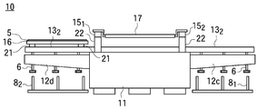
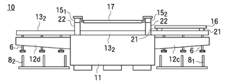
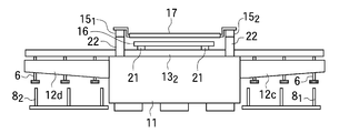
- Plan view for explaining the operation of the substrate stage of the present invention (1) Side view for explaining the operation of the substrate stage of the present invention (1) Plan view for explaining the operation of the substrate stage of the present invention (2) Side view for explaining the operation of the substrate stage of the present invention (2) Plan view for explaining the operation of the substrate stage of the present invention (3) Side view for explaining the operation of the substrate stage of the present invention (3) Plan view for explaining the operation of the substrate stage of the present invention (4) Side view for explaining the operation of the substrate stage of the present invention (4)
- the top view for demonstrating the substrate stage of this invention Side view for explaining a substrate stage of the present invention
- the top view which shows the auxiliary
- the substrate stage 10 of the present invention includes one main mounting table 11 and a plurality of (four in this case) auxiliary mountings whose planar shape is smaller and smaller in area than the main mounting table 11.
- 9 and 10 are a plan view and a side view of the substrate stage 10 according to the present invention in a state where it is temporarily assembled at the manufacturing site.
- the main mounting table 11 and the auxiliary mounting tables 12a to 12d have a quadrangular planar shape and a flat surface.
- the main mounting table 11 and the auxiliary mounting tables 12a to 12d are configured to be detachable, and two auxiliary mounting tables 12a to 12d are fixed to two sides of the main mounting table 11 that are parallel to each other.
- the lower rails 13 1 and 13 2 are longer than the length of the main mounting table 11, the central portion is disposed on the main mounting table 11, and one end is disposed on the auxiliary mounting tables 12 a and 12 c on one side of the main mounting table 11. The other end is arranged on the auxiliary mounting tables 12b and 12d on the other side.
- the two lower rails 13 1 and 13 2 are parallel to each other.
- the main mounting table 11 is arranged so that the surface thereof is horizontal, and the auxiliary mounting tables 12 a to 12 d are fixed to the main mounting table 11 in a state where the surface is lower than the main mounting table 11.
- a plurality of vertical adjustment devices 6 are provided on the auxiliary mounting tables 12a to 12d.
- the vertical adjustment device 6 is constituted by a screw, and each vertical adjustment device 6 is inserted upward from the bottom surface side to the front surface side of the auxiliary mounting tables 12a to 12d.
- the portions of the lower rails 13 1 and 13 2 placed on the main mounting table 11 are in close contact with the surface of the main mounting table 11, and the portions on the auxiliary mounting tables 12 a to 12 d are placed on the upper end of the vertical adjustment device 6. Yes.
- the lower rails 13 1 and 13 2 are made of granite.
- a guide for linear moving means is installed on the lower rails 13 1 and 13 2 .
- Granite has rigidity, but can be deformed in a small amount.
- Lower rails 13 1, 13 2, on the auxiliary table 12a ⁇ 12d abuts against the tip of the vertical adjustment device 6 at a plurality of positions along the longitudinal direction of the lower rail 13 1, 13 2, one By changing the heights of the tips of the plurality of vertical adjustment devices 6 that are in contact with the lower rails 13 1 and 13 2 , they can be extended linearly or curved in the vertical direction. it can. The upper end of the vertical adjustment device 6, is moved upward as a position close to the end of the lower rail 13 1, 13 2, it is possible to bend the lower rail 13 1, 13 2 upwards.
- the lower rails 13 1 and 13 2 are provided with a horizontal plane adjustment device, and the horizontal rail adjustment device can adjust the orientation of the lower rails 13 1 and 13 2 in the horizontal plane.
- a moving plate 16 made of granite is placed via a friction reducing device 21 such as an air bearing.
- a substrate moving mechanism (not shown) is operated, the moving plate 16 is moved to the lower rail. It travels on 13 1 and 13 2 so that it can be positioned on the auxiliary mounting tables 12a to 12d as well as on the main mounting table 11.
- a friction reducing device 21 is provided on the moving plate 16, an air layer is provided between the flat surface of the friction reducing device 21 and the surfaces of the lower rails 13 1 and 13 2 , and the lower rails 13 1 and 13 2 and The friction reducing device 21 and the moving plate 16 are not in contact with each other so that the moving plate 16 can travel on the lower rails 13 1 and 13 2 .
- one moving plate 16 is placed on the two lower rails 13 1 , 13 2 arranged in parallel with each other, but the three lower parts arranged in parallel with each other are used. You may make it drive
- a column 22 is erected on the outside of the two lower rails 13 1 and 13 2 on the main mounting table 11, and the two upper rails 15 1 and 15 2 are parallel to each other on the column 22.
- the lower rails 13 1 and 13 2 are arranged perpendicular to the extending direction.
- An ink jet head 17 is movably attached to the upper rails 15 1 and 15 2 .
- the upper rails 15 1 and 15 2 are longer than the width of the main mounting table 11, and both end portions are projected to the outside of the main mounting table 11.
- the head moving mechanism (not shown) is operated to move the inkjet head 17 to the upper rail 15.
- the ink jet head 17 can be positioned on the main mounting table 11 and on the outer side of the main mounting table 11.
- the upper rails 15 1 and 15 2 are arranged horizontally, and the inkjet head 17 moves in a horizontal plane.
- the moving plate 16 moves between the lower rails 13 1 and 13 2 and the upper rails 15 1 and 15 2 . It is possible to pass through a position directly below the inkjet head 17 through the gap.
- Lift pins 8 1 and 8 2 are vertically arranged below the auxiliary mounting tables 12a to 12d.
- the elevating pins 8 1 and 8 2 are attached to an elevating device, and can be moved up and down in the vertical direction.
- Through holes 14a to 14d and 19 are formed in the auxiliary mounting tables 12a to 12d and the movable plate 16, respectively.
- the through hole 19 of the moving plate 16 is directly above the through holes 14a, 14c or 14b, 14d of the auxiliary mounting tables 12a to 12d when the moving plate 16 is positioned on the auxiliary mounting tables 12a, 12c, 12b, 12d. is formed so as to be located, when raising the lift pins 81, 82 in this state, the lift pins 81, 82 passes through the through hole 14a, 14c or 14b, 14d, 19, upper end It protrudes on the surface of the moving plate 16.
- the substrate stage 10 is temporarily assembled so that the movable plate 16 and the ink jet head 17 can travel once at the manufacturing site as described above, and after confirming the manufacturing accuracy of the lower rails 13 1 , 13 2, etc., the substrate stage 10 is disassembled. Then, the auxiliary mounting tables 12a to 12d and the lower rails 13 1 and 13 2 are removed from the main mounting table 11.
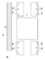
- FIG. 11 shows the auxiliary mounting tables 12a to 12d and the lower rails 13 1 and 13 2 removed from the main mounting table 11.
- the substrate stage 10 is of a size that can be transported, and disassembled members such as the main mounting table 11 and the auxiliary mounting tables 12a to 12d are placed on the vehicle and transported to a place where they are actually used.
- the main mounting table 11 is installed so that the surface is horizontal, and the auxiliary mounting tables 12a to 12d are attached to the side surface of the main mounting table 11, and assembled in the same state as before the conveyance.
- the auxiliary mounting tables 12a to 12d have one side surface fixed to the side surface of the main mounting table 11, and the portion fixed to the main mounting table 11 is supported by the main mounting table 11, whereas the side opposite to the auxiliary mounting table 12a to 12d. The part is not supported and curves downward under its own weight.
- the vertical adjustment device 6 corrects the portions of the lower rails 13 1 and 13 2 located on the auxiliary mounting tables 12a to 12d upward and the auxiliary mounting tables 12a to 12d are curved downward
- the surfaces of the lower rails 13 1 and 13 2 can be made horizontal.
- the angle of the lower rail 13 1, 13 2 in a horizontal plane to adjust the horizontal plane adjusting device the lower rail 13 1, 13 2, extends straight in a horizontal plane, two lower rails 13 1, 13 2 in a horizontal plane It becomes parallel at.
- the inkjet head 17 of the substrate stage 10 assembled at the place of use is positioned outside the main mounting table 11, the moving plate 16 is positioned on the auxiliary mounting tables 12b and 12d, and the substrate 5 is moved to the moving plate 16.
- the state arranged above is shown.
- the ink jet head 17 is connected to the discharge liquid supply system 23 in which the printing liquid is arranged, and the ink jet head 17 is moved onto the main mounting table 11 to be stationary on the main mounting table 11 as shown in FIGS. 5 and 6, the substrate 5 is moved downward of the inkjet head 17.
- a plurality of ejection holes are provided in the surface directed downward of the inkjet head 17, and the ejection mechanism provided in the inkjet head 17 is operated while supplying the printing liquid from the ejection liquid supply system 23 to the inkjet head 17.
- the liquid droplets of the printing liquid can be discharged from each discharge hole.
- the discharge holes are arranged along the width direction of the substrate (direction perpendicular to the moving direction of the substrate 5).
- the length of the region in which the ejection holes are arranged is shorter than the width of the substrate 5, and when the printing liquid is ejected from the inkjet head 17 while controlling the relative position between the inkjet head 17 and the substrate 5, the surface of the substrate 5 In the (substrate length) ⁇ (substrate width) area, the discharge liquid can be landed at a desired position within (substrate length) ⁇ (area where the discharge holes are arranged).
- the ink jet head 17 After landing the discharge liquid in the region, the ink jet head 17 is moved, the substrate 5 is moved in a state where the ink jet head 17 is stationary, and the discharge liquid on the surface of the substrate 5 is discharged toward the region where the discharge liquid is not landed.
- the discharged liquid can be landed on a desired position on the surface of the substrate 5. Since the lower rails 13 1 , 13 2 are aligned by the vertical adjustment device 6 and the horizontal adjustment device, no shaking occurs when the moving plate 16 travels, and the substrate 5 can be moved at high speed. . In addition, the landing position accuracy of the discharge liquid is improved.
- table 12a mounting auxiliary substrate 5 is moved onto the 12c, when raising the lift pins 8 1 substrate 5 on the moving base 16 It is transferred to the lifting pin 8 1 from.
- the substrate transfer robot hand is inserted between the substrate 5 and the moving table 16 and the substrate 5 is transferred onto the hand, it can be moved to the outside of the substrate stage 10.
- the inkjet head 17 when discharging the discharge liquid, the inkjet head 17 is stopped and the substrate 5 is moved to discharge the discharge liquid. However, even if the substrate 5 is stopped and the inkjet head 17 is moved to discharge the discharge liquid. Good. In short, it is only necessary that the substrate 5 and the inkjet head 17 can move relative to each other, and either one may be stationary or both may move. Instead of the inkjet head 17, other devices such as a measuring device may be attached to the upper rails 15 1 and 15 2 .
- the upper rails 15 1 and 15 2 are fixed to the main mounting table 11.
- the upper rails 15 1 and 15 2 are movably attached to the lower rails 13 1 and 13 2 , and the upper rails 15 1 and 15 2 are attached.
- the inkjet head 17 can move in two directions (XY) perpendicular to each other in the horizontal plane. It is possible to land the discharge liquid on the entire surface of the substrate 5 even if the substrate is kept stationary.
- the ink jet head 17 instead of the ink jet head 17, if an attachment device capable of attaching various devices is provided on the upper rails 15 1 and 15 2 , it can be used as a general-purpose XY stage.
- the through holes 14a to 14d are provided in the auxiliary mounting bases 12a to 12d, and the lifting pins 8 1 and 8 2 are inserted and moved up and down.
- the auxiliary mounting bases 12a to 12d are moved up and down between the auxiliary mounting bases 12a to 12d. Also good.
Landscapes
- Engineering & Computer Science (AREA)
- Mechanical Engineering (AREA)
- Ink Jet (AREA)
- Coating Apparatus (AREA)
- Details Of Measuring And Other Instruments (AREA)
Abstract
Description
近年では基板の大型化が増々進行しており、大型基板に適合するように基板ステージを大型化させた場合は、道路を搬送できない大きさになってしまう。
しかし、補助載置台を主載置台に取り付け、別々に作成したレール同士を連結すると、レールの継ぎ目に段差が発生したり、レールの水平性が確保できず、基板を高速に搬送できないという問題が発生した。
また、本発明は、前記移動板には、昇降ピンが挿通される複数の貫通孔が形成され、前記移動板が前記補助載置台の所定場所に位置する状態では、前記移動板の裏面側から前記移動板の貫通孔に前記昇降ピンを挿入できるように構成されたステージである。
また、本発明は、前記主載置台には、前記下部レールの上方に位置する上部レールが着脱可能に取り付けられたステージである。
また、本発明は、前記上部レールにはインクジェットヘッドが移動可能に取り付けられたステージである。
また、本発明は、主載置台と、前記主載置台よりも小面積で前記主載置台から分離可能な補助載置台と、前記主載置台上と前記補助載置台上に亘って配置され、前記補助載置台上には端部が位置する複数の下部レールと、前記下部レールの延びる方向に沿った移動ができるように取り付けられた上部レールと、を有するステージであって、各前記下部レールは一枚の原板から形成され、前記主載置台と前記補助載置台とに着脱可能に構成され、前記補助載置台には、前記下部レールの高さを複数位置で調節可能な上下方向調整装置が設けられ、前記上部レールと前記下部レールは着脱可能に構成されたステージである。
この場合も、本発明は、前記上部レールにはインクジェットヘッドが移動可能に取り付けられたステージである。
また、本発明は、前記下部レールはグラナイトで構成されたステージである。
本発明のステージ上には、移動板が走行する二本以上の本数の下部レールが配置されている。移動板が走行する複数の下部レールのうち、各下部レールは、それぞれ一枚の原板から形成されている。本発明には、移動板が走行する複数の下部レールが同じ原板から形成される場合と、異なる原板から形成される場合と、それらの場合が混在する場合とのいずれの場合も含まれる。
下部レールの端部には、上下方向調整装置が設けられているので、補助載置台が垂下しても直線性を維持することができる。
81、82……昇降ピン
10……基板ステージ
11……主載置台
12a~12d……補助載置台
131、132……下部レール
14a~14d、19……貫通孔
151、152……上部レール
16……移動板
17……インクジェットヘッド
図9、図10は本発明の基板ステージ10を製造場所に於いて仮に組み立てた状態の平面図と側面図である。
主載置台11と補助載置台12a~12dは着脱可能に構成されており、補助載置台12a~12dは、主載置台11の互いに平行な二辺に二個ずつ固定されている。
補助載置台12a~12dには、複数の上下方向調整装置6が設けられている。ここでは上下方向調整装置6はネジで構成されており、各上下方向調整装置6は補助載置台12a~12dの底面側から表面側に向けてそれぞれ上向きに挿通されている。
下部レール131、132上には、エアベアリング等の摩擦低減装置21を介してグラナイト製の移動板16が乗せられており、不図示の基板移動機構を動作させると移動板16は下部レール131、132上を走行し、補助載置台12a~12d上にも主載置台11上にも位置できるようにされている。
ここでは、移動板16に摩擦低減装置21を設け、摩擦低減装置21の平坦な面と下部レール131、132の表面との間に空気層を設けて、下部レール131、132と摩擦低減装置21及び移動板16とを非接触の状態にして移動板16を下部レール131、132上に乗せて走行できるようにした。
また、ここでは互いに平行に配置された二本の下部レール131、132上に亘って一台の移動板16を乗せて走行させるようにしたが、互いに平行に配置された三本の下部レール上に亘って一台の移動板を乗せて走行させるようにしても良い。
インクジェットヘッド17を主載置台11上に位置させ、移動板16上に基板5を乗せて移動させると、移動板16は、下部レール131、132と上部レール151、152の間の隙間を通って、インクジェットヘッド17の真下位置を通過することができる。
補助載置台12a~12dと移動板16には、それぞれ貫通孔14a~14d、19が形成されている。
この状態では、基板ステージ10は運搬可能な大きさになっており、主載置台11や補助載置台12a~12d等の分解した部材を車両に乗せ、実際に使用する場所まで搬送する。
補助載置台12a~12dは、一側面が主載置台11の側面に固定されており、主載置台11に固定された部分は主載置台11によって支持されているのに対し、それと反対側の部分は支持されておらず、自重で下方に湾曲する。
下部レール131、132の水平面内の角度は水平面内調整装置によって調整すると、下部レール131、132は、水平面内で一直線に伸び、二本の下部レール131、132は水平面内で平行になる。
印刷液が配置された吐出液供給系23にインクジェットヘッド17を接続し、図3、4に示すように、インクジェットヘッド17を主載置台11の上へ移動させ、主載置台11上で静止させ、図5、6に示すように、インクジェットヘッド17の下方に向けて基板5を移動させる。
下部レール131、132は、上下方向調整装置6と水平方向調整装置によって一直線にされているので移動板16が走行する際に揺れが発生せず、基板5を高速に移動させることができる。また、吐出液の着弾位置精度も向上する。
上記例では、吐出液の吐出時には、インクジェットヘッド17を静止させ、基板5を移動させて吐出液を吐出したが、基板5を静止させてインクジェットヘッド17を移動させて吐出液を吐出してもよい。要するに、基板5とインクジェットヘッド17が相対的に移動できればよく、一方が静止していても、両方が移動してもよい。
インクジェットヘッド17に替え、測定装置等の他の装置を上部レール151、152に取り付けてもよい。
また、上記例では補助載置台12a~12dに貫通孔14a~14dを設け、昇降ピン81、82を挿通させて上下移動させたが、補助載置台12a~12dの間で上下移動させてもよい。
Claims (7)
- 主載置台と、
前記主載置台よりも小面積で前記主載置台から分離可能な補助載置台と、
前記主載置台上と前記補助載置台上に亘って配置され、前記補助載置台上には端部が位置する複数の下部レールとを有し、
移動板が前記各下部レール上に位置し、前記移動板は前記下部レール上を走行可能にされたステージであって、
複数の前記下部レールは、一本が一枚の原板からそれぞれ形成され、前記主載置台と前記補助載置台とに着脱可能に構成され、
前記補助載置台には、前記下部レールの高さを複数位置で調節可能な上下方向調整装置が設けられたステージ。 - 前記移動板には、昇降ピンが挿通される複数の貫通孔が形成され、
前記移動板が前記補助載置台の所定場所に位置する状態では、前記移動板の裏面側から前記移動板の貫通孔に前記昇降ピンを挿入できるように構成された請求項1記載のステージ。 - 前記主載置台には、前記下部レールの上方に位置する上部レールが着脱可能に取り付けられた請求項1又は請求項2のいずれか1項記載のステージ。
- 前記上部レールにはインクジェットヘッドが移動可能に取り付けられた請求項3記載のステージ。
- 主載置台と、
前記主載置台よりも小面積で前記主載置台から分離可能な補助載置台と、
前記主載置台上と前記補助載置台上に亘って配置され、前記補助載置台上には端部が位置する複数の下部レールと、
前記下部レールの延びる方向に沿った移動ができるように取り付けられた上部レールと、
を有するステージであって、
各前記下部レールは一枚の原板から形成され、前記主載置台と前記補助載置台とに着脱可能に構成され、
前記補助載置台には、前記下部レールの高さを複数位置で調節可能な上下方向調整装置が設けられ、
前記上部レールと前記下部レールは着脱可能に構成されたステージ。 - 前記上部レールにはインクジェットヘッドが移動可能に取り付けられた請求項5記載のステージ。
- 前記下部レールはグラナイトで構成された請求項1乃至請求項6のいずれか1項記載のステージ。
Priority Applications (4)
| Application Number | Priority Date | Filing Date | Title |
|---|---|---|---|
| KR1020107023620A KR101245873B1 (ko) | 2008-05-19 | 2009-05-13 | 스테이지 |
| CN2009801179849A CN102037552B (zh) | 2008-05-19 | 2009-05-13 | 平台 |
| JP2010512993A JP5186560B2 (ja) | 2008-05-19 | 2009-05-13 | ステージ |
| US12/902,496 US8783674B2 (en) | 2008-05-19 | 2010-10-12 | Stage |
Applications Claiming Priority (2)
| Application Number | Priority Date | Filing Date | Title |
|---|---|---|---|
| JP2008131004 | 2008-05-19 | ||
| JP2008-131004 | 2008-05-19 |
Related Child Applications (1)
| Application Number | Title | Priority Date | Filing Date |
|---|---|---|---|
| US12/902,496 Continuation US8783674B2 (en) | 2008-05-19 | 2010-10-12 | Stage |
Publications (1)
| Publication Number | Publication Date |
|---|---|
| WO2009142133A1 true WO2009142133A1 (ja) | 2009-11-26 |
Family
ID=41340066
Family Applications (1)
| Application Number | Title | Priority Date | Filing Date |
|---|---|---|---|
| PCT/JP2009/058910 Ceased WO2009142133A1 (ja) | 2008-05-19 | 2009-05-13 | ステージ |
Country Status (6)
| Country | Link |
|---|---|
| US (1) | US8783674B2 (ja) |
| JP (1) | JP5186560B2 (ja) |
| KR (1) | KR101245873B1 (ja) |
| CN (1) | CN102037552B (ja) |
| TW (1) | TWI430383B (ja) |
| WO (1) | WO2009142133A1 (ja) |
Cited By (3)
| Publication number | Priority date | Publication date | Assignee | Title |
|---|---|---|---|---|
| JP2009279470A (ja) * | 2008-05-19 | 2009-12-03 | Ulvac Japan Ltd | ステージ |
| CN104191422A (zh) * | 2014-09-09 | 2014-12-10 | 上海华晖新材料科技有限公司 | 一种用于光滑板面金属件加工的旋转工作台 |
| JP2020028832A (ja) * | 2018-08-21 | 2020-02-27 | パナソニックIpマネジメント株式会社 | 搬送ステージとそれを使用したインクジェット装置 |
Families Citing this family (7)
| Publication number | Priority date | Publication date | Assignee | Title |
|---|---|---|---|---|
| JPWO2009116460A1 (ja) * | 2008-03-19 | 2011-07-21 | 株式会社アルバック | 基板搬送処理装置 |
| CN102037552B (zh) * | 2008-05-19 | 2013-01-23 | 株式会社爱发科 | 平台 |
| US9700976B2 (en) * | 2013-02-15 | 2017-07-11 | GM Global Technology Operations LLC | Reconfigurable interface assembly, adaptable assembly line work-piece processor, and method |
| CN103921136B (zh) * | 2014-04-29 | 2016-04-06 | 浙江博雷重型机床制造有限公司 | 一种分离式工装平台结构 |
| EP3260232B1 (de) * | 2014-08-06 | 2018-11-07 | FESTO AG & Co. KG | Positioniersystem |
| CN107745572B (zh) * | 2017-12-12 | 2019-05-24 | 佛山市顺德区振南润德印刷有限公司 | 一种印刷机台面定位治具 |
| TWI876418B (zh) * | 2022-09-15 | 2025-03-11 | 日商斯庫林集團股份有限公司 | 基板處理裝置 |
Citations (8)
| Publication number | Priority date | Publication date | Assignee | Title |
|---|---|---|---|---|
| JPH07124831A (ja) * | 1993-06-11 | 1995-05-16 | Mori Seiki Co Ltd | リニアガイド装置 |
| JPH09192567A (ja) * | 1996-01-18 | 1997-07-29 | Toray Ind Inc | 塗布装置および塗布方法並びにカラーフィルタの製造装置およびその製造方法 |
| JP2004209411A (ja) * | 2003-01-06 | 2004-07-29 | Seiko Epson Corp | 液滴吐出装置、電気光学装置、電気光学装置の製造方法および電子機器 |
| JP2007152215A (ja) * | 2005-12-05 | 2007-06-21 | Dainippon Printing Co Ltd | パターン形成装置、及びパターン形成方法 |
| WO2007105455A1 (ja) * | 2006-02-28 | 2007-09-20 | Ulvac, Inc. | ステージ装置 |
| JP2008005669A (ja) * | 2006-06-26 | 2008-01-10 | Hitachi Metals Ltd | Xyステージ |
| JP2008023699A (ja) * | 2007-03-27 | 2008-02-07 | Sumitomo Heavy Ind Ltd | ステージ装置 |
| JP2008093651A (ja) * | 2006-09-12 | 2008-04-24 | Shibaura Mechatronics Corp | ペースト塗布装置 |
Family Cites Families (23)
| Publication number | Priority date | Publication date | Assignee | Title |
|---|---|---|---|---|
| JPS55134414A (en) * | 1979-04-06 | 1980-10-20 | Hitachi Ltd | Precise moving unit |
| US4768698A (en) * | 1986-10-03 | 1988-09-06 | Pace Incorporated | X-Y table with θ rotation |
| KR0129662B1 (ko) * | 1987-10-30 | 1998-04-07 | 고다까 토시오 | 이동 테이블 장치 |
| JPH07311375A (ja) | 1994-05-17 | 1995-11-28 | Ishikawajima Harima Heavy Ind Co Ltd | 液晶ディスプレイ基板検査装置の検査ステージ |
| US5947460A (en) * | 1995-11-02 | 1999-09-07 | Tee-Lok Corporation | Truss table with integrated positioning stops |
| US5810341A (en) * | 1995-11-02 | 1998-09-22 | Tee-Lok Corporation | Truss table with integrated positioning stops |
| JPH09154635A (ja) * | 1995-12-12 | 1997-06-17 | Koizumi Sangyo Kk | 取付角度変更自在な板状体の支持装置 |
| JP2738922B2 (ja) * | 1995-12-13 | 1998-04-08 | 小泉産業株式会社 | 取付角度変更自在な板状体の支持装置 |
| CA2167849A1 (en) * | 1996-03-27 | 1997-09-28 | John Veres | Bulldog miter clamp |
| JPH1094928A (ja) * | 1996-09-24 | 1998-04-14 | Shin Nippon Koki Kk | 工作機械のテーブル移送装置 |
| US6158728A (en) * | 1999-12-01 | 2000-12-12 | Smith; Gregory C. | Workpiece holding device |
| JP4868269B2 (ja) * | 2000-03-09 | 2012-02-01 | 東レ株式会社 | 塗布方法およびカラーフィルターの製造方法 |
| US6332604B1 (en) * | 2000-08-15 | 2001-12-25 | Fair Friend Enterprise Co., Ltd. | Clamping and positioning mechanism for the inclined axis of two-axes rotary tables |
| JP3637319B2 (ja) * | 2002-02-22 | 2005-04-13 | 片山電機有限会社 | センサー機能付きアダプターテーブル |
| US6637737B1 (en) * | 2002-07-31 | 2003-10-28 | Unova Ip Corp. | Workpiece micro-positioning apparatus |
| JP2005114882A (ja) | 2003-10-06 | 2005-04-28 | Hitachi High-Tech Electronics Engineering Co Ltd | 処理ステージの基板載置方法、基板露光ステージおよび基板露光装置 |
| JP4322762B2 (ja) * | 2004-09-16 | 2009-09-02 | 住友重機械工業株式会社 | ステージガイド機構 |
| JP5108215B2 (ja) * | 2005-08-19 | 2012-12-26 | 日本碍子株式会社 | 柱状構造体の位置決め方法及び装置 |
| JP5119001B2 (ja) * | 2008-02-28 | 2013-01-16 | 株式会社日立ハイテクノロジーズ | 試料ステージ |
| CN102037552B (zh) * | 2008-05-19 | 2013-01-23 | 株式会社爱发科 | 平台 |
| US7959141B2 (en) * | 2008-12-23 | 2011-06-14 | Sumitomo Heavy Industries, Ltd. | Stage apparatus |
| JP5415123B2 (ja) * | 2009-03-31 | 2014-02-12 | 日本碍子株式会社 | 把持治具、並びに、それを用いた計測装置および把持装置 |
| CN102554638B (zh) * | 2010-12-31 | 2016-06-29 | 富泰华工业(深圳)有限公司 | 定位机台 |
-
2009
- 2009-05-13 CN CN2009801179849A patent/CN102037552B/zh not_active Expired - Fee Related
- 2009-05-13 JP JP2010512993A patent/JP5186560B2/ja not_active Expired - Fee Related
- 2009-05-13 KR KR1020107023620A patent/KR101245873B1/ko not_active Expired - Fee Related
- 2009-05-13 WO PCT/JP2009/058910 patent/WO2009142133A1/ja not_active Ceased
- 2009-05-18 TW TW098116396A patent/TWI430383B/zh not_active IP Right Cessation
-
2010
- 2010-10-12 US US12/902,496 patent/US8783674B2/en active Active
Patent Citations (8)
| Publication number | Priority date | Publication date | Assignee | Title |
|---|---|---|---|---|
| JPH07124831A (ja) * | 1993-06-11 | 1995-05-16 | Mori Seiki Co Ltd | リニアガイド装置 |
| JPH09192567A (ja) * | 1996-01-18 | 1997-07-29 | Toray Ind Inc | 塗布装置および塗布方法並びにカラーフィルタの製造装置およびその製造方法 |
| JP2004209411A (ja) * | 2003-01-06 | 2004-07-29 | Seiko Epson Corp | 液滴吐出装置、電気光学装置、電気光学装置の製造方法および電子機器 |
| JP2007152215A (ja) * | 2005-12-05 | 2007-06-21 | Dainippon Printing Co Ltd | パターン形成装置、及びパターン形成方法 |
| WO2007105455A1 (ja) * | 2006-02-28 | 2007-09-20 | Ulvac, Inc. | ステージ装置 |
| JP2008005669A (ja) * | 2006-06-26 | 2008-01-10 | Hitachi Metals Ltd | Xyステージ |
| JP2008093651A (ja) * | 2006-09-12 | 2008-04-24 | Shibaura Mechatronics Corp | ペースト塗布装置 |
| JP2008023699A (ja) * | 2007-03-27 | 2008-02-07 | Sumitomo Heavy Ind Ltd | ステージ装置 |
Cited By (4)
| Publication number | Priority date | Publication date | Assignee | Title |
|---|---|---|---|---|
| JP2009279470A (ja) * | 2008-05-19 | 2009-12-03 | Ulvac Japan Ltd | ステージ |
| CN104191422A (zh) * | 2014-09-09 | 2014-12-10 | 上海华晖新材料科技有限公司 | 一种用于光滑板面金属件加工的旋转工作台 |
| CN104191422B (zh) * | 2014-09-09 | 2016-04-06 | 上海华晖新材料科技有限公司 | 一种用于光滑板面金属件加工的旋转工作台 |
| JP2020028832A (ja) * | 2018-08-21 | 2020-02-27 | パナソニックIpマネジメント株式会社 | 搬送ステージとそれを使用したインクジェット装置 |
Also Published As
| Publication number | Publication date |
|---|---|
| CN102037552A (zh) | 2011-04-27 |
| US8783674B2 (en) | 2014-07-22 |
| KR101245873B1 (ko) | 2013-03-20 |
| TWI430383B (zh) | 2014-03-11 |
| KR20100125439A (ko) | 2010-11-30 |
| JPWO2009142133A1 (ja) | 2011-09-29 |
| TW201007871A (en) | 2010-02-16 |
| JP5186560B2 (ja) | 2013-04-17 |
| CN102037552B (zh) | 2013-01-23 |
| US20110042876A1 (en) | 2011-02-24 |
Similar Documents
| Publication | Publication Date | Title |
|---|---|---|
| JP5186560B2 (ja) | ステージ | |
| JP5124340B2 (ja) | ステージ | |
| CN103301998B (zh) | 涂布装置 | |
| CN101517400A (zh) | 基板检查装置 | |
| CN103182861B (zh) | 一种喷头模组升降控制装置以及印刷设备 | |
| JP5502788B2 (ja) | 浮上式塗布装置 | |
| CN101815659A (zh) | 可动元件和处理台 | |
| JP5369128B2 (ja) | 浮上式塗布装置 | |
| TW201801230A (zh) | 基板懸浮搬送裝置 | |
| US8100524B2 (en) | Stage apparatus | |
| JP6134201B2 (ja) | プリント基板用作業装置 | |
| KR20110034341A (ko) | 코팅 장치의 코팅 높이 조정 장치 및 방법, 및 이를 구비한 코팅 장치 | |
| CN202448510U (zh) | 一种喷头模组升降控制装置以及印刷设备 | |
| JP5121981B2 (ja) | ステージ装置 | |
| JP2007175841A (ja) | ステージ装置 | |
| JP7470749B2 (ja) | 塗布装置 | |
| KR20110020102A (ko) | 기판 부상 유닛, 및 이를 구비한 기판 이송 장치 및 코팅 장치 | |
| KR20140029694A (ko) | 부상방식의 기판 이송 장치의 높이 조절 장치 및 방법, 및 이를 구비한 부상방식의 기판 이송 장치 및 코팅 장치 | |
| KR20230095825A (ko) | 안내 장치, 워크 반송 스테이지 및 잉크젯 인쇄 장치 | |
| CN110843341B (zh) | 搬运台和使用该搬运台的喷墨装置 | |
| TW200815929A (en) | Coating apparatus | |
| JP5733745B2 (ja) | 塗布装置 | |
| KR20250167508A (ko) | 도포 장치 | |
| JP2020196063A (ja) | 搬送ステージとそれを使用したインクジェット装置 | |
| JP2011183251A (ja) | ダイコータ用分解・組立台 |
Legal Events
| Date | Code | Title | Description |
|---|---|---|---|
| WWE | Wipo information: entry into national phase |
Ref document number: 200980117984.9 Country of ref document: CN |
|
| 121 | Ep: the epo has been informed by wipo that ep was designated in this application |
Ref document number: 09750495 Country of ref document: EP Kind code of ref document: A1 |
|
| ENP | Entry into the national phase |
Ref document number: 20107023620 Country of ref document: KR Kind code of ref document: A |
|
| WWE | Wipo information: entry into national phase |
Ref document number: 2010512993 Country of ref document: JP |
|
| NENP | Non-entry into the national phase |
Ref country code: DE |
|
| 122 | Ep: pct application non-entry in european phase |
Ref document number: 09750495 Country of ref document: EP Kind code of ref document: A1 |