WO2009093549A1 - Dispositif utilisant de la chaleur résiduelle pour un moteur à combustion interne - Google Patents
Dispositif utilisant de la chaleur résiduelle pour un moteur à combustion interne Download PDFInfo
- Publication number
- WO2009093549A1 WO2009093549A1 PCT/JP2009/050685 JP2009050685W WO2009093549A1 WO 2009093549 A1 WO2009093549 A1 WO 2009093549A1 JP 2009050685 W JP2009050685 W JP 2009050685W WO 2009093549 A1 WO2009093549 A1 WO 2009093549A1
- Authority
- WO
- WIPO (PCT)
- Prior art keywords
- air
- internal combustion
- combustion engine
- heat exchange
- water
- Prior art date
Links
Images


Classifications
-
- F—MECHANICAL ENGINEERING; LIGHTING; HEATING; WEAPONS; BLASTING
- F02—COMBUSTION ENGINES; HOT-GAS OR COMBUSTION-PRODUCT ENGINE PLANTS
- F02G—HOT GAS OR COMBUSTION-PRODUCT POSITIVE-DISPLACEMENT ENGINE PLANTS; USE OF WASTE HEAT OF COMBUSTION ENGINES; NOT OTHERWISE PROVIDED FOR
- F02G5/00—Profiting from waste heat of combustion engines, not otherwise provided for
- F02G5/02—Profiting from waste heat of exhaust gases
- F02G5/04—Profiting from waste heat of exhaust gases in combination with other waste heat from combustion engines
-
- F—MECHANICAL ENGINEERING; LIGHTING; HEATING; WEAPONS; BLASTING
- F01—MACHINES OR ENGINES IN GENERAL; ENGINE PLANTS IN GENERAL; STEAM ENGINES
- F01K—STEAM ENGINE PLANTS; STEAM ACCUMULATORS; ENGINE PLANTS NOT OTHERWISE PROVIDED FOR; ENGINES USING SPECIAL WORKING FLUIDS OR CYCLES
- F01K15/00—Adaptations of plants for special use
- F01K15/02—Adaptations of plants for special use for driving vehicles, e.g. locomotives
-
- F—MECHANICAL ENGINEERING; LIGHTING; HEATING; WEAPONS; BLASTING
- F01—MACHINES OR ENGINES IN GENERAL; ENGINE PLANTS IN GENERAL; STEAM ENGINES
- F01K—STEAM ENGINE PLANTS; STEAM ACCUMULATORS; ENGINE PLANTS NOT OTHERWISE PROVIDED FOR; ENGINES USING SPECIAL WORKING FLUIDS OR CYCLES
- F01K23/00—Plants characterised by more than one engine delivering power external to the plant, the engines being driven by different fluids
- F01K23/02—Plants characterised by more than one engine delivering power external to the plant, the engines being driven by different fluids the engine cycles being thermally coupled
- F01K23/06—Plants characterised by more than one engine delivering power external to the plant, the engines being driven by different fluids the engine cycles being thermally coupled combustion heat from one cycle heating the fluid in another cycle
- F01K23/065—Plants characterised by more than one engine delivering power external to the plant, the engines being driven by different fluids the engine cycles being thermally coupled combustion heat from one cycle heating the fluid in another cycle the combustion taking place in an internal combustion piston engine, e.g. a diesel engine
-
- F—MECHANICAL ENGINEERING; LIGHTING; HEATING; WEAPONS; BLASTING
- F01—MACHINES OR ENGINES IN GENERAL; ENGINE PLANTS IN GENERAL; STEAM ENGINES
- F01K—STEAM ENGINE PLANTS; STEAM ACCUMULATORS; ENGINE PLANTS NOT OTHERWISE PROVIDED FOR; ENGINES USING SPECIAL WORKING FLUIDS OR CYCLES
- F01K9/00—Plants characterised by condensers arranged or modified to co-operate with the engines
- F01K9/003—Plants characterised by condensers arranged or modified to co-operate with the engines condenser cooling circuits
-
- F—MECHANICAL ENGINEERING; LIGHTING; HEATING; WEAPONS; BLASTING
- F01—MACHINES OR ENGINES IN GENERAL; ENGINE PLANTS IN GENERAL; STEAM ENGINES
- F01N—GAS-FLOW SILENCERS OR EXHAUST APPARATUS FOR MACHINES OR ENGINES IN GENERAL; GAS-FLOW SILENCERS OR EXHAUST APPARATUS FOR INTERNAL COMBUSTION ENGINES
- F01N5/00—Exhaust or silencing apparatus combined or associated with devices profiting from exhaust energy
- F01N5/02—Exhaust or silencing apparatus combined or associated with devices profiting from exhaust energy the devices using heat
-
- F—MECHANICAL ENGINEERING; LIGHTING; HEATING; WEAPONS; BLASTING
- F02—COMBUSTION ENGINES; HOT-GAS OR COMBUSTION-PRODUCT ENGINE PLANTS
- F02G—HOT GAS OR COMBUSTION-PRODUCT POSITIVE-DISPLACEMENT ENGINE PLANTS; USE OF WASTE HEAT OF COMBUSTION ENGINES; NOT OTHERWISE PROVIDED FOR
- F02G2260/00—Recuperating heat from exhaust gases of combustion engines and heat from cooling circuits
-
- Y—GENERAL TAGGING OF NEW TECHNOLOGICAL DEVELOPMENTS; GENERAL TAGGING OF CROSS-SECTIONAL TECHNOLOGIES SPANNING OVER SEVERAL SECTIONS OF THE IPC; TECHNICAL SUBJECTS COVERED BY FORMER USPC CROSS-REFERENCE ART COLLECTIONS [XRACs] AND DIGESTS
- Y02—TECHNOLOGIES OR APPLICATIONS FOR MITIGATION OR ADAPTATION AGAINST CLIMATE CHANGE
- Y02T—CLIMATE CHANGE MITIGATION TECHNOLOGIES RELATED TO TRANSPORTATION
- Y02T10/00—Road transport of goods or passengers
- Y02T10/10—Internal combustion engine [ICE] based vehicles
- Y02T10/12—Improving ICE efficiencies
Definitions
- the present invention relates to a waste heat utilization device for an internal combustion engine, and more particularly to a waste heat utilization device for an internal combustion engine that is suitable for being mounted on a vehicle.
- This type of internal combustion engine waste heat utilization device is mounted on a vehicle, for example, a Rankine cycle (RC circuit) that collects waste heat via cooling water that cools the vehicle engine, and an air conditioner cycle that air-conditions the vehicle interior (AC circuit).
- the RC circuit has an expander that expands the evaporative refrigerant heated by the recovered waste heat to generate a driving force, and a Rankine cycle capacitor (RC capacitor) that condenses the refrigerant that has passed through the expander with outside air. is doing.
- the AC circuit includes a compressor that compresses the evaporative refrigerant heated by the air in the passenger compartment by external power, and an air-conditioner cycle condenser (AC condenser) that condenses the refrigerant that has passed through the compressor by outside air.
- AC condenser an air-conditioner cycle condenser
- a technique is disclosed in which one shared capacitor of an RC capacitor and an AC capacitor is provided, and this shared capacitor is selectively used as an RC capacitor or an AC capacitor (see, for example, Japanese Patent Laid-Open No. 63-96449). ).
- a condenser is generally installed on the front side of the radiator that cools the engine by receiving the traveling wind from the front of the vehicle, the ventilation resistance before the radiator is increased and the ventilation amount to the radiator is increased. There is a problem that it decreases and deteriorates the heat exchange performance of the radiator.
- the ventilation resistance before the radiator can be reduced by using two RC capacitors and one AC capacitor as one common capacitor, but the common capacitor cannot be used simultaneously in the AC circuit and the RC circuit.
- the waste heat utilization device cannot be operated during the air conditioner operation, there is still a problem in improving the energy recovery efficiency of the waste heat utilization device.
- an internal combustion engine waste heat utilization apparatus comprises a cooling water circuit having a radiator for cooling cooling water heated by waste heat of the internal combustion engine by ventilation of outside air, and heating by cooling water.
- An expander that expands the generated refrigerant to generate a driving force a Rankine cycle that has a first condenser that condenses the refrigerant that has passed through the expander, a compressor that compresses the refrigerant heated by a heat source, and the compressor And a refrigeration cycle having a second condenser for condensing refrigerant flowing through the internal combustion engine, wherein the first and second condensers are water-cooled heat exchangers. It is characterized by comprising a water circuit having an air-cooling heat exchanger that cools the water that has flowed through the condenser by ventilating outside air, and a heat exchange unit that includes an air-cooling heat exchanger and a radiator.
- the refrigerant of the Rankine cycle and the refrigeration cycle can be simultaneously condensed in the first and second condensers through one air-cooled heat exchanger, so that heat exchange The energy recovery efficiency of the waste heat utilization device can be improved while reducing the ventilation resistance of the unit.
- the water circuit is required in the Rankine cycle and the refrigeration cycle while the first and second condensers are respectively connected in parallel to the air-cooled heat exchanger.
- the necessary condensation performance can be imparted to the first and second condensers as necessary, so that the refrigerant condensation performance in the first and second condensers, and consequently the energy of the waste heat utilization device. Recovery efficiency can be further improved.
- the water circuit includes the first condenser and the second condenser in the order of the second condenser and the first condenser as viewed from the direction of water flow with respect to the air-cooled heat exchanger. Connected in series.
- the waste heat utilization device improves the efficiency of the refrigeration cycle. The energy recovery efficiency can be improved.
- the first and second condensers are integrally formed. According to this configuration, it is possible to improve the energy recovery efficiency of the waste heat utilization device while realizing downsizing of the first and second condensers and securing the space of the waste heat utilization device.
- the heat exchange unit is configured by stacking an air-cooled heat exchanger and a radiator in order from the direction of the outside air.
- the heat exchange unit is configured by integrally connecting an air-cooled heat exchanger and a radiator in a direction substantially orthogonal to the direction of the outside air. According to these configurations, it is possible to improve the energy recovery efficiency of the waste heat utilization device while reducing the ventilation resistance of the heat exchange unit as compared with the case where the first and second condensers are arranged in front of the radiator. it can.
- the heat exchange unit has a blower in which the amount of outside air flowing through the air-cooled heat exchanger and the radiator is independently controlled.
- the heat exchange unit includes any one of a heat exchange unit in which heat exchange is performed independently between the air-cooled heat exchanger and the radiator, and each of the heat exchange units. And a common heat exchanger used as one of them.
- the heat transfer area of the radiator and the air-cooled heat exchanger can be increased or decreased according to the heat load of each heat exchange unit, the water cooling performance in the radiator and the air-cooled heat exchanger, The refrigerant condensing performance in the second condenser, and thus the energy recovery efficiency of the waste heat utilization apparatus can be further improved.
- the heat exchange unit includes a flow path switching unit that switches a flow path of water so that the shared heat exchange section is used as one of the heat exchange sections. .
- the heat transfer area of the radiator and the air-cooled heat exchanger can be increased or decreased more smoothly, so the water cooling performance in the radiator and the air-cooled heat exchanger, The refrigerant condensing performance in the first and second condensers, and hence the energy recovery efficiency of the waste heat utilization device can be further improved.
- the heat exchange unit includes a plurality of shared heat exchange units.
- FIG. 1 is a schematic diagram schematically showing a waste heat utilization device for an internal combustion engine according to a first embodiment of the present invention
- FIG. 1 is a longitudinal sectional view schematically showing only the front side of a vehicle on which the waste heat utilization apparatus of FIG. 1 is mounted
- FIG. 2 is a perspective view schematically showing only the front side of the vehicle in FIG. 2 from above.
- FIG. 5 is a perspective view schematically showing only the front side of the vehicle from above when the shared heat exchange part of FIG.
- FIG. 5 is used as a heat exchange part of an air-cooled heat exchanger;
- FIG. 5 is a perspective view schematically showing only the front side of the vehicle when the common heat exchange part of FIG. 5 is enlarged or formed as a heat exchange part of an air-cooled heat exchanger.
- the schematic diagram which showed roughly only the water circuit among the waste heat utilization apparatuses of the internal combustion engine which concerns on the modification of this invention,
- FIG. 9 is a schematic diagram schematically showing an integrated capacitor of the AC capacitor and the RC capacitor in FIG. 8.
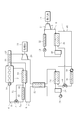
- FIG. 1 is a schematic diagram schematically showing the configuration of the waste heat utilization apparatus for an internal combustion engine according to the present embodiment.
- the waste heat utilization device is mounted on a vehicle, a cooling water circuit 4 that cools the engine 2 of the vehicle, a Rankine cycle circuit (Rankine cycle) 6 (hereinafter referred to as an RC circuit) that collects waste heat of the engine 2,
- An air conditioner cycle circuit (refrigeration cycle) 8 (hereinafter referred to as an AC circuit) that performs air conditioning of a vehicle interior (not shown) is provided.
- the cooling water circuit 4 forms a closed circuit by inserting an evaporator 10, a radiator 12, a thermostat 14, and a water pump 16 into a cooling water circulation path 5 extending from the engine 2 in order from the flow direction of the cooling water. is doing.
- the evaporator 10 exchanges heat between the cooling water of the cooling water circuit 4 and the refrigerant of the RC circuit 6, thereby using the cooling water heated by the engine 2, that is, warm water as a heat medium, and the waste heat of the engine 2 as the RC circuit 6. It is collected by absorbing heat to the side.
- the cooling water absorbed by the refrigerant after passing through the evaporator 10 becomes warm water heated again by cooling the engine 2.
- the radiator 12 is arranged in series with the evaporator 10 and further cools the cooling water that has passed through the evaporator 10 and has been absorbed by the refrigerant by heat exchange with the outside air.
- the thermostat 14 is a mechanical three-way valve that controls the amount of cooling water that is passed to the radiator 12 according to the cooling water temperature, and has two inlet ports and one outlet port.
- the two inlet ports are connected to a flow path 5a extending from the radiator 12 and a bypass path 5c connected to bypass the radiator 12 from the flow path 5b between the evaporator 10 and the radiator 12, respectively.
- the amount of cooling water passed to the radiator 12 is increased or decreased according to the cooling water temperature, and the engine 2 is prevented from being overheated or overcooled.
- the water pump 16 is attached to the engine 2 and is driven according to the rotational speed of the engine 2 to circulate the cooling water in the cooling water circuit 4 appropriately.
- the RC circuit 6 is connected to the refrigerant circulation path 7 in the order of the refrigerant flow direction, the evaporator 10, the heater 18, the expander 20, the regenerator 22, the Rankine cycle condenser (first condenser) 24 (hereinafter referred to as RC).
- the gas-liquid separator 26 and the refrigerant pump 28 are inserted to form a closed circuit.
- the heater 18 is an exhaust gas heat exchanger that heats the refrigerant with the exhaust gas of the engine 4 that flows through the exhaust gas pipe 19, and further heats the refrigerant heated by the evaporator 10.
- the expander 20 is a fluid device that expands the refrigerant heated to the superheated steam state by the evaporator 10 and generates a rotational driving force.
- the expander 20 converts the generated rotational driving force into electric power.
- the generator 30 that can be used outside the waste heat utilization apparatus is mechanically connected.
- the regenerator 22 is an internal heat exchanger of the RC circuit 6 that heats the refrigerant at the inlet of the evaporator 10 with the refrigerant at the outlet of the expander 20, and positively transfers the heat amount at the outlet of the expander 20 to the inlet side of the evaporator 10.
- the RC condenser 24 is a heat exchanger that condenses and liquefies the refrigerant that has passed through the regenerator 22.
- the gas-liquid separator 26 is a receiver that separates the refrigerant condensed by the RC capacitor 24 into two layers of gas and liquid, and only the liquid refrigerant separated here flows out to the refrigerant pump 28 side.
- the refrigerant pump 28 is an electric pump that is driven in accordance with a signal input to the drive unit, and the liquid refrigerant that has flowed out of the gas-liquid separator 26 is pumped to the evaporator 10 side by the refrigerant pump 28 and is supplied to the RC circuit. 6 is circulated suitably.
- the AC circuit 8 is connected to the refrigerant circulation path 9 in the order of the refrigerant flow direction, the air-conditioner cycle evaporator 32, the compressor 34, the air-conditioner cycle condenser (second condenser) 36 (hereinafter referred to as AC condenser), gas-liquid A separator 38 and an expansion valve 40 are inserted to form a closed circuit.
- the air conditioner cycle evaporator 32 is a heat exchanger that exchanges heat between the air in the vehicle interior of the vehicle and the refrigerant circulating in the AC circuit 8, and evaporates the refrigerant using the air in the vehicle interior as a heat source.
- the compressor 34 is driven by a mechanically connected power source 42 and compresses the refrigerant evaporated by the evaporator 32 to a superheated steam state.
- the AC condenser 36 is a heat exchanger that condenses and liquefies the refrigerant discharged from the compressor 34.
- the liquid refrigerant condensed by the AC condenser 36 is sent to the expansion valve 40 through the gas-liquid separator 38, and the expansion valve 40. After being expanded via, it is sent out to the evaporator 32.
- the heat exchange method of the RC capacitor 24 and the AC capacitor 36 is a water cooling type
- the waste heat utilization device is a water in which each capacitor 24, 36 is inserted in addition to the circuits 4, 6, 8.
- a circuit 44 is further provided.
- an air-cooling heat exchanger 46 for interposing the water used for condensing and liquefying the refrigerant in the capacitors 24 and 36 with outside air is inserted.
- the water circuit 44 is configured such that the condensers 24 and 36 are connected in parallel to the water circulation path 45 with respect to the air-cooling heat exchanger 46, and at the branch point from the air-cooling heat exchanger 46 to the condensers 24 and 36.
- a linearly driven three-way valve (flow distribution means) 48 is provided, and a water pump 50 is attached to the water inlet of the air-cooling heat exchanger 46.
- FIG. 2 schematically shows a longitudinal sectional view of only the front surface 52a side of the vehicle 52 on which the waste heat utilization device is mounted.
- the engine 2 is mounted on the lower part of the hood 52b of the vehicle 52, and the air cooling heat exchanger 46 and the radiator 12 are arranged in the front-rear direction of the vehicle 52 on the front surface 52a side of the engine 2 in order from the front surface 52a side.
- An exchange unit 53 is configured.
- the traveling air 54 is passed through the heat exchange unit 53 as the vehicle 52 travels, and heat exchange is performed between the water circulating in the water circuit 44 and the cooling water circulating in the cooling water circuit 4.
- the air-cooling heat exchanger 46 and the fans (blowers) 56a and 56b shared by the radiator 12 are arranged on the rear side of the radiator 12,
- the fans 56a and 56b control the air flow rate of the running air 54 that is ventilated to the air-cooling heat exchanger 46 and thus to the radiator 12.
- the waste heat utilization apparatus configured in this way distributes the water to the capacitors 24 and 36 by driving the three-way valve 48 according to the refrigerant condensing capacity required in the circuits 6 and 8. Control is in progress.
- the drive unit of the three-way valve 48 is electrically connected to an electronic control unit (ECU) (not shown) that controls the vehicle 52 and the waste heat utilization device, and the ECU does not use the AC circuit 8 in winter, for example.
- ECU electronice control unit
- the three-way valve 48 is switched to the RC condenser 24 side, so that the entire amount of water circulating through the water circuit 44 flows into the RC condenser 24.
- the ECU selects the three-way valve 48 when the RC circuit 6 does not recover the waste heat from the engine 2.
- the entire amount of water circulating through the water circuit 44 flows into the AC condenser 36.
- the ECU opens the three-way valve 48 toward the AC capacitor 36 in order to reduce the water flowing into the RC capacitor 24.
- the ECU performs water flow distribution control for the capacitors 24 and 36 in accordance with the operation status of the vehicle 52 and the waste heat utilization device.
- the energy recovery efficiency of the waste heat utilization apparatus can be improved by improving the condensation performance of the refrigerant in each of the capacitors 24 and 36.
- the refrigerant in each circuit 6 and 8 can be simultaneously condensed by each condenser 24 and 36 via one air-cooled heat exchanger 46, so that the ventilation resistance of the heat exchange unit 53 is reduced.
- the condensation performance of the refrigerant in each of the capacitors 24 and 36 can be improved.
- the ECU performs the flow rate distribution control of the water to the capacitors 24 and 36, it is possible to give the condensers 24 and 36 the necessary condensation performance as necessary.
- the condensation performance can be further improved.
- the heat exchange efficiency in the capacitors 24 and 36 can be improved.
- the condensation performance can be further improved.
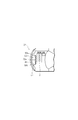
- the second embodiment constitutes a heat exchange unit 57 in which the air-cooling heat exchanger 46 and the radiator 12 of the first embodiment are integrally connected in the width direction of the vehicle 52, and the others are the first embodiment. It has the same configuration as
- FIG. 4 is a perspective view of the front side 52a of the vehicle 52 of this embodiment as viewed from above.
- the radiator 12 is formed larger than the air cooling heat exchanger 46, and the air cooling heat exchanger 46 and the radiator 12 are formed.
- the rotational speeds of the fans 56a and 56b disposed on the rear surface of the fan 56 are independently controlled.
- FIG. 5 is a schematic diagram showing the heat exchange units 12a and 46a of the radiator 12 and the air-cooled heat exchanger 46. In each of the heat exchange units 12a and 46a, heat of water and outside air is independently used. Exchange is performed.
- the heat exchange part 12a has a larger heat transfer area than the heat exchange part 46a, and any of the heat exchange parts 12a, 46a is between the heat exchange part 12a and the heat exchange part 46a.
- a common heat exchanging portion 58 that can be used as one of them is formed.
- the common heat exchanging part 58 is connected in parallel to the heat exchanging part 12a by extending the circulation path 5 extending from the engine 2, and by extending the circulation path 45 extending from the RC condenser 24 or the AC condenser 36.
- the heat exchange part 46a is connected in parallel.
- on-off valves 64a and 64b and on-off valves 66a and 66b are respectively inserted before and after the common heat exchange section 58.
- each on-off valve (flow path switching means) 64a, 64b, 66a, 66b is electrically connected to the ECU, and the ECU determines whether the on-off valve 64a is in accordance with the heat load of each heat exchange unit 12a, 46a. 64b, or the on-off valves 66a and 66b are collectively opened and closed to switch the flow path of the water in the extension passages 60 and 62, thereby using the common heat exchanging portion 58 as either one of the heat exchanging portions 12a and 46a.
- the flow path switching control is performed.
- the on-off valves 64 a and 64 b are closed together, while the on-off valves 66 a and 66 b are opened together, so that there is a margin in the heat load of the radiator 12.
- the common heat exchanger 58 is used as the heat exchanger 46a of the air-cooling heat exchanger 46, and as shown in FIG. 6, the heat transfer area of the air-cooling heat exchanger 46 is increased to increase the cooling capacity. .
- the shared heat exchanging portion 58 when the shared heat exchanging portion 58 is used as the heat exchanging portion 12a of the radiator 12 and then used as the heat exchanging portion 46a of the air-cooled heat exchanger 46, for example, after cooling the engine 2
- the water after being condensed by the RC condenser 24 or the AC condenser 36 is about 40 ° C., so that the on-off valves 64a and 64b are collectively closed.
- the on-off valves 66a and 66b are collectively opened to switch the water flow path. Is preferred.
- the size of the heat transfer section of the air-cooled heat exchanger 46 in other words, the size of the heat transfer area of each heat exchange section 12a, 46a can be varied more flexibly according to these heat loads.
- the energy recovery efficiency of the waste heat utilization device can be improved by improving the refrigerant condensing performance in each of the capacitors 24 and 36 as in the first embodiment.
- the heat transfer area of the radiator 12 and the air cooling heat exchanger 46 can be increased or decreased according to the heat load of the heat exchange portions 12a, 46a of the radiator 12 and the air cooling heat exchanger 46, Water cooling performance in the radiator 12 and the air cooling heat exchanger 46 can be improved.
- the cooling water used for cooling the engine 2 can be used for cooling the water in the heat exchanging portion 46a of the air-cooling heat exchanger 46 after the temperature is lowered, the efficiency of the AC cycle or RC cycle is deteriorated. Can be prevented.
- the increase / decrease width of the heat transfer area of the radiator 12 and the air cooling heat exchanger 46 can be increased. Therefore, the radiator 12 and the air cooling heat exchanger The water cooling performance in 46 can be further improved, which is preferable.
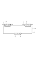
- the capacitors 24 and 36 are connected in parallel to the air-cooling heat exchanger 46.
- the present invention is not limited to this, and as shown in FIG.
- the AC capacitor 36 and the RC capacitor 24 may be connected in series to the cold heat exchanger as viewed from the direction of water flow.
- the three-way valve 48 is not necessary, and the water circulating in the water circuit 44 flows into the AC condenser 36 and the RC condenser 24 in this order, and heat exchange is performed step by step. It is preferable that the ventilation resistance of the heat exchange unit 53 can be reduced while giving priority to the performance.
- the capacitors 24 and 36 are described as separate capacitors.
- the present invention is not limited to this, and the circulation path 45 is branched and merged as shown in FIG.
- An integrated capacitor 68 having a water flow path may be formed, and the capacitors 24 and 36 may be formed integrally. In this case, a larger space can be secured in the vehicle 52, which is preferable.
Abstract
L'invention porte sur un dispositif utilisant de la chaleur résiduelle pour un moteur à combustion interne (2), le dispositif comprenant un circuit d'eau de refroidissement (4) ayant un radiateur (12) pour refroidir l'eau de refroidissement avec l'aspiration d'air ambiant, un cycle de Rankine (6) ayant un premier condenseur (24) pour condenser un milieu de refroidissement, et un cycle de réfrigération (8) ayant un second condenseur (36) pour condenser le milieu de refroidissement. Les premiers et seconds condenseurs (24 et 36) sont des échangeurs de chaleur refroidis à l'eau, et comprennent un circuit d'eau (44) ayant un échangeur de chaleur refroidi à l'air (46) pour refroidir l'eau qui est passée par les premiers et seconds condenseurs (24 et 36), avec l'aspiration de l'air ambiant, et une unité d'échange de chaleur (53) composée de l'échangeur de chaleur refroidi à l'air (46) et du radiateur (12).
Priority Applications (3)
| Application Number | Priority Date | Filing Date | Title |
|---|---|---|---|
| EP09703920A EP2236803A4 (fr) | 2008-01-21 | 2009-01-19 | Dispositif utilisant de la chaleur résiduelle pour un moteur à combustion interne |
| US12/863,956 US20100294217A1 (en) | 2008-01-21 | 2009-01-19 | Waste Heat Utilization Device for Internal Combustion Engine |
| CN2009801031818A CN101918695A (zh) | 2008-01-21 | 2009-01-19 | 内燃机的废热利用装置 |
Applications Claiming Priority (2)
| Application Number | Priority Date | Filing Date | Title |
|---|---|---|---|
| JP2008-010363 | 2008-01-21 | ||
| JP2008010363A JP2009167994A (ja) | 2008-01-21 | 2008-01-21 | 内燃機関の廃熱利用装置 |
Publications (1)
| Publication Number | Publication Date |
|---|---|
| WO2009093549A1 true WO2009093549A1 (fr) | 2009-07-30 |
Family
ID=40901057
Family Applications (1)
| Application Number | Title | Priority Date | Filing Date |
|---|---|---|---|
| PCT/JP2009/050685 WO2009093549A1 (fr) | 2008-01-21 | 2009-01-19 | Dispositif utilisant de la chaleur résiduelle pour un moteur à combustion interne |
Country Status (5)
| Country | Link |
|---|---|
| US (1) | US20100294217A1 (fr) |
| EP (1) | EP2236803A4 (fr) |
| JP (1) | JP2009167994A (fr) |
| CN (1) | CN101918695A (fr) |
| WO (1) | WO2009093549A1 (fr) |
Cited By (4)
| Publication number | Priority date | Publication date | Assignee | Title |
|---|---|---|---|---|
| FR2950572A1 (fr) * | 2009-09-29 | 2011-04-01 | Renault Sa | Systeme et procede de controle de la temperature de l'habitacle d'un vehicule automobile |
| JP2011117716A (ja) * | 2009-11-04 | 2011-06-16 | Valeo Systemes Thermiques | 少なくとも3つの熱交換部を備える熱交換器、およびかかる熱交換器を含む熱エネルギー管理システム |
| WO2013129569A1 (fr) * | 2012-03-02 | 2013-09-06 | ヤンマー株式会社 | Système de récupération de chaleur perdue à cycle de rankine |
| JP2019173698A (ja) * | 2018-03-29 | 2019-10-10 | トヨタ自動車株式会社 | 車両駆動装置の冷却装置 |
Families Citing this family (39)
| Publication number | Priority date | Publication date | Assignee | Title |
|---|---|---|---|---|
| EP2320058B1 (fr) * | 2008-08-26 | 2015-11-25 | Sanden Corporation | Dispositif d utilisation de chaleur résiduelle pour moteur à combustion interne |
| DE102009028467A1 (de) | 2009-08-12 | 2011-02-17 | Robert Bosch Gmbh | Vorrichtung zur Nutzung von Abwärme |
| JP5338731B2 (ja) * | 2010-03-29 | 2013-11-13 | 株式会社豊田自動織機 | 廃熱回生システム |
| JP5976644B2 (ja) | 2010-07-14 | 2016-08-24 | マック トラックス インコーポレイテッド | 部分的な復熱を伴う廃熱回収システム |
| WO2012078195A1 (fr) | 2010-12-10 | 2012-06-14 | Vaporgenics,Inc. | Moteur thermique universel |
| SE1150169A1 (sv) * | 2011-02-25 | 2012-06-26 | Scania Cv Ab | System för att omvandla värmeenergi till mekanisk energi i ett fordon |
| JP2012251516A (ja) * | 2011-06-06 | 2012-12-20 | Toyota Industries Corp | 廃熱回収装置 |
| US20140250886A1 (en) * | 2011-09-30 | 2014-09-11 | Sanden Corporation | Rankine Cycle |
| US9562444B2 (en) * | 2011-09-30 | 2017-02-07 | Nissan Motor Co., Ltd. | Engine waste-heat utilization device |
| JP2014238007A (ja) * | 2011-09-30 | 2014-12-18 | 日産自動車株式会社 | ランキンサイクルシステム |
| CN103233947A (zh) * | 2012-01-08 | 2013-08-07 | 钱荣华 | 一种冷却煤矿井下挖掘装载机及其它设备液压油的方法 |
| CN102691555B (zh) * | 2012-04-12 | 2014-04-16 | 北京工业大学 | 带蓄热器的内燃机排气余热回收系统及控制方法 |
| CN102678235A (zh) * | 2012-06-13 | 2012-09-19 | 苏州鑫瑞汽车节能技术有限公司 | 一种内燃机动力辅助系统 |
| DE102012022865B4 (de) * | 2012-11-20 | 2014-08-21 | Iav Gmbh Ingenieurgesellschaft Auto Und Verkehr | Vorrichtung zur Nutzung der Abwärme einer Brennkraftmaschine |
| JP2014126344A (ja) * | 2012-12-27 | 2014-07-07 | Nissan Motor Co Ltd | 熱交換システム |
| DE102013205648A1 (de) * | 2012-12-27 | 2014-07-03 | Robert Bosch Gmbh | System zur Energierückgewinnung aus einem Abwärmestrom einer Brennkraftmaschine |
| US9316141B2 (en) * | 2013-02-15 | 2016-04-19 | Enis Pilavdzic | Engine energy management system |
| KR101965654B1 (ko) * | 2013-03-28 | 2019-04-03 | 한온시스템 주식회사 | 자동차 |
| FR3006749B1 (fr) * | 2013-06-05 | 2015-07-03 | Suez Environnement | Procede de production d'energie par combustion de matieres, et installation pour la mise en oeuvre du procede. |
| US20150000274A1 (en) * | 2013-06-28 | 2015-01-01 | Cummins Inc. | Waste heat recovery system including connection to a vehicle air conditioning system |
| JP2015014222A (ja) * | 2013-07-04 | 2015-01-22 | 株式会社テイエルブイ | 蒸気タービン発電装置 |
| EP2829700B1 (fr) * | 2013-07-27 | 2024-01-10 | Meyer, Edo | Système de gestion d'énergie de moteur |
| JP6387245B2 (ja) * | 2014-05-15 | 2018-09-05 | 日産自動車株式会社 | エンジンの廃熱利用装置 |
| JP5796664B1 (ja) * | 2014-05-26 | 2015-10-21 | カルソニックカンセイ株式会社 | 冷却システム |
| JP6495608B2 (ja) * | 2014-10-09 | 2019-04-03 | サンデンホールディングス株式会社 | 廃熱回収装置 |
| FR3030702B1 (fr) * | 2014-12-17 | 2019-09-13 | Valeo Systemes Thermiques | Circuit de gestion thermique d'un vehicule automobile et procede de pilotage associe |
| FR3044707B1 (fr) * | 2015-12-08 | 2018-01-12 | Psa Automobiles Sa. | Ensemble moteur comprenant un convertisseur thermo-acoustique |
| JP6665003B2 (ja) * | 2016-03-18 | 2020-03-13 | パナソニック株式会社 | コージェネレーション装置 |
| SE542064C2 (en) * | 2017-06-07 | 2020-02-18 | Scania Cv Ab | A cooling system for a combustion engine and a WHR system |
| EP3447256B1 (fr) | 2017-08-25 | 2023-11-01 | Orcan Energy AG | Système de refroidissement pour un fluide provenant d'une installation produisant de la chaleur |
| CN107939548B (zh) * | 2017-10-17 | 2020-06-23 | 山东大学 | 新型内燃机余热利用冷热电联供系统及其工作方法 |
| JP2019120163A (ja) * | 2017-12-28 | 2019-07-22 | サンデンホールディングス株式会社 | 車両用廃熱回収装置 |
| JP7057129B2 (ja) * | 2017-12-28 | 2022-04-19 | サンデン株式会社 | 車両用廃熱回収装置 |
| EP3881019A4 (fr) * | 2018-11-13 | 2022-08-03 | Lochterra Inc. | Systèmes et procédés pour la capture de l'énergie thermique, le transport à longue distance, le stockage et la distribution de l'énergie thermique capturée et de l'énergie générée à partir de ceux-ci |
| US11137177B1 (en) | 2019-03-16 | 2021-10-05 | Vaporgemics, Inc | Internal return pump |
| DE102019115909A1 (de) * | 2019-06-12 | 2020-12-17 | Volkswagen Aktiengesellschaft | Verbrennungsmotor mit Abgaswärmerückgewinnungssystem sowie Verfahren zur Abgaswärmerückgewinnung |
| DE102019208650A1 (de) * | 2019-06-13 | 2020-12-17 | Volkswagen Aktiengesellschaft | Antriebseinheit für ein Kraftfahrzeug mit einer ersten Kreisprozessvorrichtung und einer zweiten Kreisprozessvorrichtung |
| JP7294186B2 (ja) * | 2020-03-02 | 2023-06-20 | トヨタ自動車株式会社 | 熱交換システム、方法、プログラム、及び車両 |
| CN115341990A (zh) * | 2022-08-19 | 2022-11-15 | 奇瑞汽车股份有限公司 | 发动机进气冷却装置及车辆 |
Citations (4)
| Publication number | Priority date | Publication date | Assignee | Title |
|---|---|---|---|---|
| JPS5812819A (ja) * | 1981-07-17 | 1983-01-25 | Hitachi Ltd | 車両用冷凍機 |
| JPS6396449A (ja) | 1986-10-13 | 1988-04-27 | 株式会社デンソー | 車両搭載用の排熱利用装置 |
| JP2004308424A (ja) * | 2003-04-01 | 2004-11-04 | Denso Corp | 内燃機関の廃熱利用装置 |
| JP2006144744A (ja) * | 2004-11-24 | 2006-06-08 | Toyota Industries Corp | 車両用排熱回収システム |
Family Cites Families (18)
| Publication number | Priority date | Publication date | Assignee | Title |
|---|---|---|---|---|
| US4099489A (en) * | 1975-10-06 | 1978-07-11 | Bradley Curtis E | Fuel regenerated non-polluting internal combustion engine |
| US4342200A (en) * | 1975-11-12 | 1982-08-03 | Daeco Fuels And Engineering Company | Combined engine cooling system and waste-heat driven heat pump |
| US4022272A (en) * | 1975-11-14 | 1977-05-10 | Chester O. Houston, Jr. | Transmission fluid heat radiator |
| US4253307A (en) * | 1979-08-27 | 1981-03-03 | Smith Derrick A | Solar power generator and water purifier |
| FR2490724B1 (fr) * | 1980-09-19 | 1985-10-25 | Melchior Jean | Perfectionnements aux moteurs a combustion interne fortement suralimentes et equipes d'un systeme de refroidissement par air et aux systemes de refroidissement pour de tels moteurs |
| JPS6189926A (ja) * | 1984-10-11 | 1986-05-08 | Toyota Motor Corp | 空冷式インタ−ク−ラ構造 |
| US5103645A (en) * | 1990-06-22 | 1992-04-14 | Thermon Manufacturing Company | Internal combustion engine and method |
| US5327987A (en) * | 1992-04-02 | 1994-07-12 | Abdelmalek Fawzy T | High efficiency hybrid car with gasoline engine, and electric battery powered motor |
| IT1272684B (it) * | 1993-09-27 | 1997-06-26 | Gianluigi Reis | Sistema di ricupero energia dissipata, durante la sua marcia, da un veicolo a motore a combustione interna |
| US5910099A (en) * | 1997-02-28 | 1999-06-08 | General Motors Corporation | Turbocharged engine cooling system control with fuel economy optimization |
| US6397596B1 (en) * | 2001-04-30 | 2002-06-04 | Heather Boyle | Self contained generation system using waste heat as an energy source |
| US6880344B2 (en) * | 2002-11-13 | 2005-04-19 | Utc Power, Llc | Combined rankine and vapor compression cycles |
| KR100528392B1 (ko) * | 2003-01-27 | 2005-11-15 | 가부시키가이샤 덴소 | 냉동 사이클 및 랭킨 사이클을 갖는 증기-압축 냉동사이클 시스템 |
| US6996988B1 (en) * | 2003-01-28 | 2006-02-14 | Emc2 | AutoSolar Thermal Electric Conversion (ASTEC) solar power system |
| JP2005030312A (ja) * | 2003-07-14 | 2005-02-03 | Toyota Industries Corp | 膨張機兼圧縮機 |
| JP2005155336A (ja) * | 2003-11-20 | 2005-06-16 | Denso Corp | ランキンサイクルおよび熱サイクル |
| US7181919B2 (en) * | 2004-03-31 | 2007-02-27 | Denso Corporation | System utilizing waste heat of internal combustion engine |
| JP4543920B2 (ja) * | 2004-12-22 | 2010-09-15 | 株式会社デンソー | 熱機関の廃熱利用装置 |
-
2008
- 2008-01-21 JP JP2008010363A patent/JP2009167994A/ja active Pending
-
2009
- 2009-01-19 WO PCT/JP2009/050685 patent/WO2009093549A1/fr active Application Filing
- 2009-01-19 EP EP09703920A patent/EP2236803A4/fr not_active Withdrawn
- 2009-01-19 CN CN2009801031818A patent/CN101918695A/zh active Pending
- 2009-01-19 US US12/863,956 patent/US20100294217A1/en not_active Abandoned
Patent Citations (4)
| Publication number | Priority date | Publication date | Assignee | Title |
|---|---|---|---|---|
| JPS5812819A (ja) * | 1981-07-17 | 1983-01-25 | Hitachi Ltd | 車両用冷凍機 |
| JPS6396449A (ja) | 1986-10-13 | 1988-04-27 | 株式会社デンソー | 車両搭載用の排熱利用装置 |
| JP2004308424A (ja) * | 2003-04-01 | 2004-11-04 | Denso Corp | 内燃機関の廃熱利用装置 |
| JP2006144744A (ja) * | 2004-11-24 | 2006-06-08 | Toyota Industries Corp | 車両用排熱回収システム |
Non-Patent Citations (1)
| Title |
|---|
| See also references of EP2236803A4 * |
Cited By (7)
| Publication number | Priority date | Publication date | Assignee | Title |
|---|---|---|---|---|
| FR2950572A1 (fr) * | 2009-09-29 | 2011-04-01 | Renault Sa | Systeme et procede de controle de la temperature de l'habitacle d'un vehicule automobile |
| WO2011039447A1 (fr) * | 2009-09-29 | 2011-04-07 | Renault S.A.S. | Systeme et procede de controle de la temperature de l'habitacle d'un vehicule automobile |
| JP2011117716A (ja) * | 2009-11-04 | 2011-06-16 | Valeo Systemes Thermiques | 少なくとも3つの熱交換部を備える熱交換器、およびかかる熱交換器を含む熱エネルギー管理システム |
| WO2013129569A1 (fr) * | 2012-03-02 | 2013-09-06 | ヤンマー株式会社 | Système de récupération de chaleur perdue à cycle de rankine |
| US9581050B2 (en) | 2012-03-02 | 2017-02-28 | Yanmar Co., Ltd. | Waste heat recovery ranking cycle system |
| JP2019173698A (ja) * | 2018-03-29 | 2019-10-10 | トヨタ自動車株式会社 | 車両駆動装置の冷却装置 |
| CN110315960A (zh) * | 2018-03-29 | 2019-10-11 | 丰田自动车株式会社 | 车辆驱动装置的冷却装置 |
Also Published As
| Publication number | Publication date |
|---|---|
| CN101918695A (zh) | 2010-12-15 |
| JP2009167994A (ja) | 2009-07-30 |
| EP2236803A4 (fr) | 2011-03-16 |
| US20100294217A1 (en) | 2010-11-25 |
| EP2236803A1 (fr) | 2010-10-06 |
Similar Documents
| Publication | Publication Date | Title |
|---|---|---|
| WO2009093549A1 (fr) | Dispositif utilisant de la chaleur résiduelle pour un moteur à combustion interne | |
| JP2009167995A (ja) | 内燃機関の廃熱利用装置 | |
| CN109501552B (zh) | 用于车辆的热泵系统 | |
| JP4654655B2 (ja) | 蒸気圧縮式冷凍機 | |
| JP2021031045A (ja) | 車両用ヒートポンプシステム | |
| JP6304578B2 (ja) | 車両用空調装置 | |
| CN112074425A (zh) | 车用热管理系统 | |
| JP2021000971A (ja) | 車両用ヒートポンプシステム | |
| JP2007278624A (ja) | ヒートポンプサイクル | |
| JP2004515394A (ja) | 自動車の温度を調節するための改良されたヒートポンプ装置 | |
| JPWO2016059791A1 (ja) | 車両用空調装置 | |
| JP2006046763A (ja) | 廃熱利用装置を備える冷凍装置 | |
| JP2010115993A (ja) | 車両用空調装置 | |
| WO2016103578A1 (fr) | Dispositif de conditionnement d'air | |
| JP2021147044A (ja) | 車室の空気を空調して自動車の駆動部品を通じて熱伝達するためのシステム及びそのシステムの動作方法 | |
| CN109982877B (zh) | 车辆热泵系统 | |
| JP2009097481A (ja) | 内燃機関の廃熱利用装置 | |
| JP5096956B2 (ja) | 車両用空気調和システム | |
| JP5130083B2 (ja) | 内燃機関の廃熱利用装置 | |
| JP6315222B2 (ja) | 車両用空調装置の構成ユニット | |
| JP2006232145A (ja) | 車両用空調装置 | |
| CN113650478A (zh) | 汽车热管理空调系统和新能源汽车 | |
| JP2010038108A (ja) | 内燃機関の廃熱利用装置 | |
| CN112313099A (zh) | 用于车辆的热处理系统 | |
| KR20190098068A (ko) | 차량용 열관리 시스템 |
Legal Events
| Date | Code | Title | Description |
|---|---|---|---|
| WWE | Wipo information: entry into national phase |
Ref document number: 200980103181.8 Country of ref document: CN |
|
| 121 | Ep: the epo has been informed by wipo that ep was designated in this application |
Ref document number: 09703920 Country of ref document: EP Kind code of ref document: A1 |
|
| WWE | Wipo information: entry into national phase |
Ref document number: 2009703920 Country of ref document: EP |
|
| WWE | Wipo information: entry into national phase |
Ref document number: 12863956 Country of ref document: US |
|
| NENP | Non-entry into the national phase |
Ref country code: DE |