WO2009093549A1 - Waste heat utilizing device for internal combustion engine - Google Patents
Waste heat utilizing device for internal combustion engine Download PDFInfo
- Publication number
- WO2009093549A1 WO2009093549A1 PCT/JP2009/050685 JP2009050685W WO2009093549A1 WO 2009093549 A1 WO2009093549 A1 WO 2009093549A1 JP 2009050685 W JP2009050685 W JP 2009050685W WO 2009093549 A1 WO2009093549 A1 WO 2009093549A1
- Authority
- WO
- WIPO (PCT)
- Prior art keywords
- air
- internal combustion
- combustion engine
- heat exchange
- water
- Prior art date
Links
Images


Classifications
-
- F—MECHANICAL ENGINEERING; LIGHTING; HEATING; WEAPONS; BLASTING
- F02—COMBUSTION ENGINES; HOT-GAS OR COMBUSTION-PRODUCT ENGINE PLANTS
- F02G—HOT GAS OR COMBUSTION-PRODUCT POSITIVE-DISPLACEMENT ENGINE PLANTS; USE OF WASTE HEAT OF COMBUSTION ENGINES; NOT OTHERWISE PROVIDED FOR
- F02G5/00—Profiting from waste heat of combustion engines, not otherwise provided for
- F02G5/02—Profiting from waste heat of exhaust gases
- F02G5/04—Profiting from waste heat of exhaust gases in combination with other waste heat from combustion engines
-
- F—MECHANICAL ENGINEERING; LIGHTING; HEATING; WEAPONS; BLASTING
- F01—MACHINES OR ENGINES IN GENERAL; ENGINE PLANTS IN GENERAL; STEAM ENGINES
- F01K—STEAM ENGINE PLANTS; STEAM ACCUMULATORS; ENGINE PLANTS NOT OTHERWISE PROVIDED FOR; ENGINES USING SPECIAL WORKING FLUIDS OR CYCLES
- F01K15/00—Adaptations of plants for special use
- F01K15/02—Adaptations of plants for special use for driving vehicles, e.g. locomotives
-
- F—MECHANICAL ENGINEERING; LIGHTING; HEATING; WEAPONS; BLASTING
- F01—MACHINES OR ENGINES IN GENERAL; ENGINE PLANTS IN GENERAL; STEAM ENGINES
- F01K—STEAM ENGINE PLANTS; STEAM ACCUMULATORS; ENGINE PLANTS NOT OTHERWISE PROVIDED FOR; ENGINES USING SPECIAL WORKING FLUIDS OR CYCLES
- F01K23/00—Plants characterised by more than one engine delivering power external to the plant, the engines being driven by different fluids
- F01K23/02—Plants characterised by more than one engine delivering power external to the plant, the engines being driven by different fluids the engine cycles being thermally coupled
- F01K23/06—Plants characterised by more than one engine delivering power external to the plant, the engines being driven by different fluids the engine cycles being thermally coupled combustion heat from one cycle heating the fluid in another cycle
- F01K23/065—Plants characterised by more than one engine delivering power external to the plant, the engines being driven by different fluids the engine cycles being thermally coupled combustion heat from one cycle heating the fluid in another cycle the combustion taking place in an internal combustion piston engine, e.g. a diesel engine
-
- F—MECHANICAL ENGINEERING; LIGHTING; HEATING; WEAPONS; BLASTING
- F01—MACHINES OR ENGINES IN GENERAL; ENGINE PLANTS IN GENERAL; STEAM ENGINES
- F01K—STEAM ENGINE PLANTS; STEAM ACCUMULATORS; ENGINE PLANTS NOT OTHERWISE PROVIDED FOR; ENGINES USING SPECIAL WORKING FLUIDS OR CYCLES
- F01K9/00—Plants characterised by condensers arranged or modified to co-operate with the engines
- F01K9/003—Plants characterised by condensers arranged or modified to co-operate with the engines condenser cooling circuits
-
- F—MECHANICAL ENGINEERING; LIGHTING; HEATING; WEAPONS; BLASTING
- F01—MACHINES OR ENGINES IN GENERAL; ENGINE PLANTS IN GENERAL; STEAM ENGINES
- F01N—GAS-FLOW SILENCERS OR EXHAUST APPARATUS FOR MACHINES OR ENGINES IN GENERAL; GAS-FLOW SILENCERS OR EXHAUST APPARATUS FOR INTERNAL COMBUSTION ENGINES
- F01N5/00—Exhaust or silencing apparatus combined or associated with devices profiting from exhaust energy
- F01N5/02—Exhaust or silencing apparatus combined or associated with devices profiting from exhaust energy the devices using heat
-
- F—MECHANICAL ENGINEERING; LIGHTING; HEATING; WEAPONS; BLASTING
- F02—COMBUSTION ENGINES; HOT-GAS OR COMBUSTION-PRODUCT ENGINE PLANTS
- F02G—HOT GAS OR COMBUSTION-PRODUCT POSITIVE-DISPLACEMENT ENGINE PLANTS; USE OF WASTE HEAT OF COMBUSTION ENGINES; NOT OTHERWISE PROVIDED FOR
- F02G2260/00—Recuperating heat from exhaust gases of combustion engines and heat from cooling circuits
-
- Y—GENERAL TAGGING OF NEW TECHNOLOGICAL DEVELOPMENTS; GENERAL TAGGING OF CROSS-SECTIONAL TECHNOLOGIES SPANNING OVER SEVERAL SECTIONS OF THE IPC; TECHNICAL SUBJECTS COVERED BY FORMER USPC CROSS-REFERENCE ART COLLECTIONS [XRACs] AND DIGESTS
- Y02—TECHNOLOGIES OR APPLICATIONS FOR MITIGATION OR ADAPTATION AGAINST CLIMATE CHANGE
- Y02T—CLIMATE CHANGE MITIGATION TECHNOLOGIES RELATED TO TRANSPORTATION
- Y02T10/00—Road transport of goods or passengers
- Y02T10/10—Internal combustion engine [ICE] based vehicles
- Y02T10/12—Improving ICE efficiencies
Definitions
- the present invention relates to a waste heat utilization device for an internal combustion engine, and more particularly to a waste heat utilization device for an internal combustion engine that is suitable for being mounted on a vehicle.
- This type of internal combustion engine waste heat utilization device is mounted on a vehicle, for example, a Rankine cycle (RC circuit) that collects waste heat via cooling water that cools the vehicle engine, and an air conditioner cycle that air-conditions the vehicle interior (AC circuit).
- the RC circuit has an expander that expands the evaporative refrigerant heated by the recovered waste heat to generate a driving force, and a Rankine cycle capacitor (RC capacitor) that condenses the refrigerant that has passed through the expander with outside air. is doing.
- the AC circuit includes a compressor that compresses the evaporative refrigerant heated by the air in the passenger compartment by external power, and an air-conditioner cycle condenser (AC condenser) that condenses the refrigerant that has passed through the compressor by outside air.
- AC condenser an air-conditioner cycle condenser
- a technique is disclosed in which one shared capacitor of an RC capacitor and an AC capacitor is provided, and this shared capacitor is selectively used as an RC capacitor or an AC capacitor (see, for example, Japanese Patent Laid-Open No. 63-96449). ).
- a condenser is generally installed on the front side of the radiator that cools the engine by receiving the traveling wind from the front of the vehicle, the ventilation resistance before the radiator is increased and the ventilation amount to the radiator is increased. There is a problem that it decreases and deteriorates the heat exchange performance of the radiator.
- the ventilation resistance before the radiator can be reduced by using two RC capacitors and one AC capacitor as one common capacitor, but the common capacitor cannot be used simultaneously in the AC circuit and the RC circuit.
- the waste heat utilization device cannot be operated during the air conditioner operation, there is still a problem in improving the energy recovery efficiency of the waste heat utilization device.
- an internal combustion engine waste heat utilization apparatus comprises a cooling water circuit having a radiator for cooling cooling water heated by waste heat of the internal combustion engine by ventilation of outside air, and heating by cooling water.
- An expander that expands the generated refrigerant to generate a driving force a Rankine cycle that has a first condenser that condenses the refrigerant that has passed through the expander, a compressor that compresses the refrigerant heated by a heat source, and the compressor And a refrigeration cycle having a second condenser for condensing refrigerant flowing through the internal combustion engine, wherein the first and second condensers are water-cooled heat exchangers. It is characterized by comprising a water circuit having an air-cooling heat exchanger that cools the water that has flowed through the condenser by ventilating outside air, and a heat exchange unit that includes an air-cooling heat exchanger and a radiator.
- the refrigerant of the Rankine cycle and the refrigeration cycle can be simultaneously condensed in the first and second condensers through one air-cooled heat exchanger, so that heat exchange The energy recovery efficiency of the waste heat utilization device can be improved while reducing the ventilation resistance of the unit.
- the water circuit is required in the Rankine cycle and the refrigeration cycle while the first and second condensers are respectively connected in parallel to the air-cooled heat exchanger.
- the necessary condensation performance can be imparted to the first and second condensers as necessary, so that the refrigerant condensation performance in the first and second condensers, and consequently the energy of the waste heat utilization device. Recovery efficiency can be further improved.
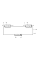
- the water circuit includes the first condenser and the second condenser in the order of the second condenser and the first condenser as viewed from the direction of water flow with respect to the air-cooled heat exchanger. Connected in series.
- the waste heat utilization device improves the efficiency of the refrigeration cycle. The energy recovery efficiency can be improved.
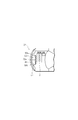
- the first and second condensers are integrally formed. According to this configuration, it is possible to improve the energy recovery efficiency of the waste heat utilization device while realizing downsizing of the first and second condensers and securing the space of the waste heat utilization device.
- the heat exchange unit is configured by stacking an air-cooled heat exchanger and a radiator in order from the direction of the outside air.
- the heat exchange unit is configured by integrally connecting an air-cooled heat exchanger and a radiator in a direction substantially orthogonal to the direction of the outside air. According to these configurations, it is possible to improve the energy recovery efficiency of the waste heat utilization device while reducing the ventilation resistance of the heat exchange unit as compared with the case where the first and second condensers are arranged in front of the radiator. it can.
- the heat exchange unit has a blower in which the amount of outside air flowing through the air-cooled heat exchanger and the radiator is independently controlled.
- the heat exchange unit includes any one of a heat exchange unit in which heat exchange is performed independently between the air-cooled heat exchanger and the radiator, and each of the heat exchange units. And a common heat exchanger used as one of them.
- the heat transfer area of the radiator and the air-cooled heat exchanger can be increased or decreased according to the heat load of each heat exchange unit, the water cooling performance in the radiator and the air-cooled heat exchanger, The refrigerant condensing performance in the second condenser, and thus the energy recovery efficiency of the waste heat utilization apparatus can be further improved.
- the heat exchange unit includes a flow path switching unit that switches a flow path of water so that the shared heat exchange section is used as one of the heat exchange sections. .
- the heat transfer area of the radiator and the air-cooled heat exchanger can be increased or decreased more smoothly, so the water cooling performance in the radiator and the air-cooled heat exchanger, The refrigerant condensing performance in the first and second condensers, and hence the energy recovery efficiency of the waste heat utilization device can be further improved.
- the heat exchange unit includes a plurality of shared heat exchange units.
- FIG. 1 is a schematic diagram schematically showing a waste heat utilization device for an internal combustion engine according to a first embodiment of the present invention
- FIG. 1 is a longitudinal sectional view schematically showing only the front side of a vehicle on which the waste heat utilization apparatus of FIG. 1 is mounted
- FIG. 2 is a perspective view schematically showing only the front side of the vehicle in FIG. 2 from above.
- FIG. 5 is a perspective view schematically showing only the front side of the vehicle from above when the shared heat exchange part of FIG.
- FIG. 5 is used as a heat exchange part of an air-cooled heat exchanger;
- FIG. 5 is a perspective view schematically showing only the front side of the vehicle when the common heat exchange part of FIG. 5 is enlarged or formed as a heat exchange part of an air-cooled heat exchanger.
- the schematic diagram which showed roughly only the water circuit among the waste heat utilization apparatuses of the internal combustion engine which concerns on the modification of this invention,
- FIG. 9 is a schematic diagram schematically showing an integrated capacitor of the AC capacitor and the RC capacitor in FIG. 8.
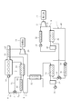
- FIG. 1 is a schematic diagram schematically showing the configuration of the waste heat utilization apparatus for an internal combustion engine according to the present embodiment.
- the waste heat utilization device is mounted on a vehicle, a cooling water circuit 4 that cools the engine 2 of the vehicle, a Rankine cycle circuit (Rankine cycle) 6 (hereinafter referred to as an RC circuit) that collects waste heat of the engine 2,
- An air conditioner cycle circuit (refrigeration cycle) 8 (hereinafter referred to as an AC circuit) that performs air conditioning of a vehicle interior (not shown) is provided.
- the cooling water circuit 4 forms a closed circuit by inserting an evaporator 10, a radiator 12, a thermostat 14, and a water pump 16 into a cooling water circulation path 5 extending from the engine 2 in order from the flow direction of the cooling water. is doing.
- the evaporator 10 exchanges heat between the cooling water of the cooling water circuit 4 and the refrigerant of the RC circuit 6, thereby using the cooling water heated by the engine 2, that is, warm water as a heat medium, and the waste heat of the engine 2 as the RC circuit 6. It is collected by absorbing heat to the side.
- the cooling water absorbed by the refrigerant after passing through the evaporator 10 becomes warm water heated again by cooling the engine 2.
- the radiator 12 is arranged in series with the evaporator 10 and further cools the cooling water that has passed through the evaporator 10 and has been absorbed by the refrigerant by heat exchange with the outside air.
- the thermostat 14 is a mechanical three-way valve that controls the amount of cooling water that is passed to the radiator 12 according to the cooling water temperature, and has two inlet ports and one outlet port.
- the two inlet ports are connected to a flow path 5a extending from the radiator 12 and a bypass path 5c connected to bypass the radiator 12 from the flow path 5b between the evaporator 10 and the radiator 12, respectively.
- the amount of cooling water passed to the radiator 12 is increased or decreased according to the cooling water temperature, and the engine 2 is prevented from being overheated or overcooled.
- the water pump 16 is attached to the engine 2 and is driven according to the rotational speed of the engine 2 to circulate the cooling water in the cooling water circuit 4 appropriately.
- the RC circuit 6 is connected to the refrigerant circulation path 7 in the order of the refrigerant flow direction, the evaporator 10, the heater 18, the expander 20, the regenerator 22, the Rankine cycle condenser (first condenser) 24 (hereinafter referred to as RC).
- the gas-liquid separator 26 and the refrigerant pump 28 are inserted to form a closed circuit.
- the heater 18 is an exhaust gas heat exchanger that heats the refrigerant with the exhaust gas of the engine 4 that flows through the exhaust gas pipe 19, and further heats the refrigerant heated by the evaporator 10.
- the expander 20 is a fluid device that expands the refrigerant heated to the superheated steam state by the evaporator 10 and generates a rotational driving force.
- the expander 20 converts the generated rotational driving force into electric power.
- the generator 30 that can be used outside the waste heat utilization apparatus is mechanically connected.
- the regenerator 22 is an internal heat exchanger of the RC circuit 6 that heats the refrigerant at the inlet of the evaporator 10 with the refrigerant at the outlet of the expander 20, and positively transfers the heat amount at the outlet of the expander 20 to the inlet side of the evaporator 10.
- the RC condenser 24 is a heat exchanger that condenses and liquefies the refrigerant that has passed through the regenerator 22.
- the gas-liquid separator 26 is a receiver that separates the refrigerant condensed by the RC capacitor 24 into two layers of gas and liquid, and only the liquid refrigerant separated here flows out to the refrigerant pump 28 side.
- the refrigerant pump 28 is an electric pump that is driven in accordance with a signal input to the drive unit, and the liquid refrigerant that has flowed out of the gas-liquid separator 26 is pumped to the evaporator 10 side by the refrigerant pump 28 and is supplied to the RC circuit. 6 is circulated suitably.
- the AC circuit 8 is connected to the refrigerant circulation path 9 in the order of the refrigerant flow direction, the air-conditioner cycle evaporator 32, the compressor 34, the air-conditioner cycle condenser (second condenser) 36 (hereinafter referred to as AC condenser), gas-liquid A separator 38 and an expansion valve 40 are inserted to form a closed circuit.
- the air conditioner cycle evaporator 32 is a heat exchanger that exchanges heat between the air in the vehicle interior of the vehicle and the refrigerant circulating in the AC circuit 8, and evaporates the refrigerant using the air in the vehicle interior as a heat source.
- the compressor 34 is driven by a mechanically connected power source 42 and compresses the refrigerant evaporated by the evaporator 32 to a superheated steam state.
- the AC condenser 36 is a heat exchanger that condenses and liquefies the refrigerant discharged from the compressor 34.
- the liquid refrigerant condensed by the AC condenser 36 is sent to the expansion valve 40 through the gas-liquid separator 38, and the expansion valve 40. After being expanded via, it is sent out to the evaporator 32.
- the heat exchange method of the RC capacitor 24 and the AC capacitor 36 is a water cooling type
- the waste heat utilization device is a water in which each capacitor 24, 36 is inserted in addition to the circuits 4, 6, 8.
- a circuit 44 is further provided.
- an air-cooling heat exchanger 46 for interposing the water used for condensing and liquefying the refrigerant in the capacitors 24 and 36 with outside air is inserted.
- the water circuit 44 is configured such that the condensers 24 and 36 are connected in parallel to the water circulation path 45 with respect to the air-cooling heat exchanger 46, and at the branch point from the air-cooling heat exchanger 46 to the condensers 24 and 36.
- a linearly driven three-way valve (flow distribution means) 48 is provided, and a water pump 50 is attached to the water inlet of the air-cooling heat exchanger 46.
- FIG. 2 schematically shows a longitudinal sectional view of only the front surface 52a side of the vehicle 52 on which the waste heat utilization device is mounted.
- the engine 2 is mounted on the lower part of the hood 52b of the vehicle 52, and the air cooling heat exchanger 46 and the radiator 12 are arranged in the front-rear direction of the vehicle 52 on the front surface 52a side of the engine 2 in order from the front surface 52a side.
- An exchange unit 53 is configured.
- the traveling air 54 is passed through the heat exchange unit 53 as the vehicle 52 travels, and heat exchange is performed between the water circulating in the water circuit 44 and the cooling water circulating in the cooling water circuit 4.
- the air-cooling heat exchanger 46 and the fans (blowers) 56a and 56b shared by the radiator 12 are arranged on the rear side of the radiator 12,
- the fans 56a and 56b control the air flow rate of the running air 54 that is ventilated to the air-cooling heat exchanger 46 and thus to the radiator 12.
- the waste heat utilization apparatus configured in this way distributes the water to the capacitors 24 and 36 by driving the three-way valve 48 according to the refrigerant condensing capacity required in the circuits 6 and 8. Control is in progress.
- the drive unit of the three-way valve 48 is electrically connected to an electronic control unit (ECU) (not shown) that controls the vehicle 52 and the waste heat utilization device, and the ECU does not use the AC circuit 8 in winter, for example.
- ECU electronice control unit
- the three-way valve 48 is switched to the RC condenser 24 side, so that the entire amount of water circulating through the water circuit 44 flows into the RC condenser 24.
- the ECU selects the three-way valve 48 when the RC circuit 6 does not recover the waste heat from the engine 2.
- the entire amount of water circulating through the water circuit 44 flows into the AC condenser 36.
- the ECU opens the three-way valve 48 toward the AC capacitor 36 in order to reduce the water flowing into the RC capacitor 24.
- the ECU performs water flow distribution control for the capacitors 24 and 36 in accordance with the operation status of the vehicle 52 and the waste heat utilization device.
- the energy recovery efficiency of the waste heat utilization apparatus can be improved by improving the condensation performance of the refrigerant in each of the capacitors 24 and 36.
- the refrigerant in each circuit 6 and 8 can be simultaneously condensed by each condenser 24 and 36 via one air-cooled heat exchanger 46, so that the ventilation resistance of the heat exchange unit 53 is reduced.
- the condensation performance of the refrigerant in each of the capacitors 24 and 36 can be improved.
- the ECU performs the flow rate distribution control of the water to the capacitors 24 and 36, it is possible to give the condensers 24 and 36 the necessary condensation performance as necessary.
- the condensation performance can be further improved.
- the heat exchange efficiency in the capacitors 24 and 36 can be improved.
- the condensation performance can be further improved.
- the second embodiment constitutes a heat exchange unit 57 in which the air-cooling heat exchanger 46 and the radiator 12 of the first embodiment are integrally connected in the width direction of the vehicle 52, and the others are the first embodiment. It has the same configuration as
- FIG. 4 is a perspective view of the front side 52a of the vehicle 52 of this embodiment as viewed from above.
- the radiator 12 is formed larger than the air cooling heat exchanger 46, and the air cooling heat exchanger 46 and the radiator 12 are formed.
- the rotational speeds of the fans 56a and 56b disposed on the rear surface of the fan 56 are independently controlled.
- FIG. 5 is a schematic diagram showing the heat exchange units 12a and 46a of the radiator 12 and the air-cooled heat exchanger 46. In each of the heat exchange units 12a and 46a, heat of water and outside air is independently used. Exchange is performed.
- the heat exchange part 12a has a larger heat transfer area than the heat exchange part 46a, and any of the heat exchange parts 12a, 46a is between the heat exchange part 12a and the heat exchange part 46a.
- a common heat exchanging portion 58 that can be used as one of them is formed.
- the common heat exchanging part 58 is connected in parallel to the heat exchanging part 12a by extending the circulation path 5 extending from the engine 2, and by extending the circulation path 45 extending from the RC condenser 24 or the AC condenser 36.
- the heat exchange part 46a is connected in parallel.
- on-off valves 64a and 64b and on-off valves 66a and 66b are respectively inserted before and after the common heat exchange section 58.
- each on-off valve (flow path switching means) 64a, 64b, 66a, 66b is electrically connected to the ECU, and the ECU determines whether the on-off valve 64a is in accordance with the heat load of each heat exchange unit 12a, 46a. 64b, or the on-off valves 66a and 66b are collectively opened and closed to switch the flow path of the water in the extension passages 60 and 62, thereby using the common heat exchanging portion 58 as either one of the heat exchanging portions 12a and 46a.
- the flow path switching control is performed.
- the on-off valves 64 a and 64 b are closed together, while the on-off valves 66 a and 66 b are opened together, so that there is a margin in the heat load of the radiator 12.
- the common heat exchanger 58 is used as the heat exchanger 46a of the air-cooling heat exchanger 46, and as shown in FIG. 6, the heat transfer area of the air-cooling heat exchanger 46 is increased to increase the cooling capacity. .
- the shared heat exchanging portion 58 when the shared heat exchanging portion 58 is used as the heat exchanging portion 12a of the radiator 12 and then used as the heat exchanging portion 46a of the air-cooled heat exchanger 46, for example, after cooling the engine 2
- the water after being condensed by the RC condenser 24 or the AC condenser 36 is about 40 ° C., so that the on-off valves 64a and 64b are collectively closed.
- the on-off valves 66a and 66b are collectively opened to switch the water flow path. Is preferred.
- the size of the heat transfer section of the air-cooled heat exchanger 46 in other words, the size of the heat transfer area of each heat exchange section 12a, 46a can be varied more flexibly according to these heat loads.
- the energy recovery efficiency of the waste heat utilization device can be improved by improving the refrigerant condensing performance in each of the capacitors 24 and 36 as in the first embodiment.
- the heat transfer area of the radiator 12 and the air cooling heat exchanger 46 can be increased or decreased according to the heat load of the heat exchange portions 12a, 46a of the radiator 12 and the air cooling heat exchanger 46, Water cooling performance in the radiator 12 and the air cooling heat exchanger 46 can be improved.
- the cooling water used for cooling the engine 2 can be used for cooling the water in the heat exchanging portion 46a of the air-cooling heat exchanger 46 after the temperature is lowered, the efficiency of the AC cycle or RC cycle is deteriorated. Can be prevented.
- the increase / decrease width of the heat transfer area of the radiator 12 and the air cooling heat exchanger 46 can be increased. Therefore, the radiator 12 and the air cooling heat exchanger The water cooling performance in 46 can be further improved, which is preferable.
- the capacitors 24 and 36 are connected in parallel to the air-cooling heat exchanger 46.
- the present invention is not limited to this, and as shown in FIG.
- the AC capacitor 36 and the RC capacitor 24 may be connected in series to the cold heat exchanger as viewed from the direction of water flow.
- the three-way valve 48 is not necessary, and the water circulating in the water circuit 44 flows into the AC condenser 36 and the RC condenser 24 in this order, and heat exchange is performed step by step. It is preferable that the ventilation resistance of the heat exchange unit 53 can be reduced while giving priority to the performance.
- the capacitors 24 and 36 are described as separate capacitors.
- the present invention is not limited to this, and the circulation path 45 is branched and merged as shown in FIG.
- An integrated capacitor 68 having a water flow path may be formed, and the capacitors 24 and 36 may be formed integrally. In this case, a larger space can be secured in the vehicle 52, which is preferable.
Abstract
Disclosed is a waste heat utilizing device for an internal combustion engine (2), which comprises a cooling water circuit (4) having a radiator (12) for cooling the cooling water with the draft of ambient air, a Rankine cycle (6) having a first condenser (24) for condensing a cooling medium, and a refrigerating cycle (8) having a second condenser (36) for condensing the cooling medium. The first and second condensers (24 and 36) are water-cooled heat exchangers, and include a water circuit (44) having an air-cooled heat exchanger (46) for cooling the water having passed the first and second condensers (24 and 36), with the draft of the ambient air, and a heat-exchanging unit (53) composed of the air-cooled heat exchanger (46) and the radiator (12).
Description
本発明は、内燃機関の廃熱利用装置に係り、詳しくは、車両に搭載されて好適な内燃機関の廃熱利用装置に関する。
The present invention relates to a waste heat utilization device for an internal combustion engine, and more particularly to a waste heat utilization device for an internal combustion engine that is suitable for being mounted on a vehicle.
この種の内燃機関の廃熱利用装置は、例えば車両に搭載され、車両のエンジンを冷却する冷却水を介して廃熱を回収するランキンサイクル(RC回路)と、車室内の空調を行うエアコンサイクル(AC回路)とを備えている。
RC回路は、回収された廃熱によって加熱された蒸発冷媒を膨張させて駆動力を発生する膨張機と、この膨張機を流通した冷媒を外気により凝縮させるランキンサイクルコンデンサ(RCコンデンサ)とを有している。
一方、AC回路は、車室内の空気によって加熱された蒸発冷媒を外部動力によって圧縮する圧縮機と、この圧縮機を流通した冷媒を外気により凝縮させるエアコンサイクルコンデンサ(ACコンデンサ)とを有している。 This type of internal combustion engine waste heat utilization device is mounted on a vehicle, for example, a Rankine cycle (RC circuit) that collects waste heat via cooling water that cools the vehicle engine, and an air conditioner cycle that air-conditions the vehicle interior (AC circuit).
The RC circuit has an expander that expands the evaporative refrigerant heated by the recovered waste heat to generate a driving force, and a Rankine cycle capacitor (RC capacitor) that condenses the refrigerant that has passed through the expander with outside air. is doing.
On the other hand, the AC circuit includes a compressor that compresses the evaporative refrigerant heated by the air in the passenger compartment by external power, and an air-conditioner cycle condenser (AC condenser) that condenses the refrigerant that has passed through the compressor by outside air. Yes.
そして、RCコンデンサ及びACコンデンサの共用コンデンサを1つ設け、この共用コンデンサをRCコンデンサまたはACコンデンサとして選択的に使用する技術が開示されている(例えば、日本国特開昭63-96449号公報参照)。
しかしながら、このようなコンデンサは、一般に、車両の前面からの走行風を受けてエンジンを冷却するラジエータの前側に重ねて設置されるため、ラジエータ手前における通風抵抗が増大してラジエータへの通風量が減少し、ラジエータの熱交換性能を悪化させるとの問題がある。
上記従来技術では、2つのRCコンデンサ及びACコンデンサを1つの共用コンデンサとすることによってラジエータ手前における通風抵抗を低減することができるものの、共用コンデンサをAC回路及びRC回路において同時に使用することができず、エアコン運転時には廃熱利用装置を運転することができないため、廃熱利用装置のエネルギー回収効率の向上には依然として課題が残されている。 A technique is disclosed in which one shared capacitor of an RC capacitor and an AC capacitor is provided, and this shared capacitor is selectively used as an RC capacitor or an AC capacitor (see, for example, Japanese Patent Laid-Open No. 63-96449). ).
However, since such a condenser is generally installed on the front side of the radiator that cools the engine by receiving the traveling wind from the front of the vehicle, the ventilation resistance before the radiator is increased and the ventilation amount to the radiator is increased. There is a problem that it decreases and deteriorates the heat exchange performance of the radiator.
In the above prior art, the ventilation resistance before the radiator can be reduced by using two RC capacitors and one AC capacitor as one common capacitor, but the common capacitor cannot be used simultaneously in the AC circuit and the RC circuit. However, since the waste heat utilization device cannot be operated during the air conditioner operation, there is still a problem in improving the energy recovery efficiency of the waste heat utilization device.
本発明は、このような課題に鑑みてなされたもので、廃熱利用装置のエネルギー回収効率を大幅に向上することができる内燃機関の廃熱利用装置を提供することを目的とする。
上記の目的を達成するべく、本発明の内燃機関の廃熱利用装置は、内燃機関の廃熱によって加熱された冷却水を外気の通風により冷却させるラジエータを有する冷却水回路と、冷却水によって加熱された冷媒を膨張させて駆動力を発生する膨張機、該膨張機を流通した冷媒を凝縮させる第1凝縮器を有するランキンサイクルと、熱源によって加熱された冷媒を圧縮する圧縮機、該圧縮機を流通した冷媒を凝縮させる第2凝縮器を有する冷凍サイクルとを備えた内燃機関の廃熱利用装置であって、第1及び第2凝縮器は水冷熱交換器であり、第1及び第2凝縮器を流通した水を外気の通風により冷却させる空冷熱交換器を有する水回路と、空冷熱交換器とラジエータとからなる熱交換ユニットとを備えることを特徴としている。 This invention is made | formed in view of such a subject, and it aims at providing the waste-heat utilization apparatus of the internal combustion engine which can improve the energy recovery efficiency of a waste-heat utilization apparatus significantly.
In order to achieve the above object, an internal combustion engine waste heat utilization apparatus according to the present invention comprises a cooling water circuit having a radiator for cooling cooling water heated by waste heat of the internal combustion engine by ventilation of outside air, and heating by cooling water. An expander that expands the generated refrigerant to generate a driving force, a Rankine cycle that has a first condenser that condenses the refrigerant that has passed through the expander, a compressor that compresses the refrigerant heated by a heat source, and the compressor And a refrigeration cycle having a second condenser for condensing refrigerant flowing through the internal combustion engine, wherein the first and second condensers are water-cooled heat exchangers. It is characterized by comprising a water circuit having an air-cooling heat exchanger that cools the water that has flowed through the condenser by ventilating outside air, and a heat exchange unit that includes an air-cooling heat exchanger and a radiator.
上記した内燃機関の廃熱利用装置によれば、1つの空冷熱交換器を介して第1及び第2凝縮器にてそれぞれランキンサイクル、冷凍サイクルの冷媒を同時に凝縮させることができるため、熱交換ユニットの通風抵抗を低減しつつ、廃熱利用装置のエネルギー回収効率を向上することができる。
好適な態様として、上記した内燃機関の廃熱利用装置において、水回路は、第1及び第2凝縮器が空冷熱交換器に対してそれぞれ並列に接続されるとともに、ランキンサイクル及び冷凍サイクルにおいて要求される冷媒の凝縮能力に応じて、第1凝縮器と第2凝縮器とに水を配分して流通させる流量配分手段を有する。
この構成によれば、第1及び第2凝縮器に必要に応じて必要な凝縮性能を付与することができるため、第1及び第2凝縮器における冷媒の凝縮性能、ひいては廃熱利用装置のエネルギー回収効率を更に向上することができる。 According to the above-described waste heat utilization apparatus for an internal combustion engine, the refrigerant of the Rankine cycle and the refrigeration cycle can be simultaneously condensed in the first and second condensers through one air-cooled heat exchanger, so that heat exchange The energy recovery efficiency of the waste heat utilization device can be improved while reducing the ventilation resistance of the unit.
As a preferred aspect, in the above-described waste heat utilization apparatus for an internal combustion engine, the water circuit is required in the Rankine cycle and the refrigeration cycle while the first and second condensers are respectively connected in parallel to the air-cooled heat exchanger. According to the condensing capacity of the refrigerant to be provided, there is a flow rate distribution means for distributing and distributing water to the first condenser and the second condenser.
According to this configuration, the necessary condensation performance can be imparted to the first and second condensers as necessary, so that the refrigerant condensation performance in the first and second condensers, and consequently the energy of the waste heat utilization device. Recovery efficiency can be further improved.
好適な態様として、上記した内燃機関の廃熱利用装置において、水回路は、第1及び第2凝縮器が空冷熱交換器に対する水の流れ方向からみて第2凝縮器、第1凝縮器の順に直列に接続される。
この構成によれば、水回路を循環する水が第2凝縮器、第1凝縮器の順に流入されて段階的に熱交換が行われるため、冷凍サイクルの効率を向上しつつ、廃熱利用装置のエネルギー回収効率を向上することができる。
好適な態様として、上記した内燃機関の廃熱利用装置において、第1及び第2凝縮器は一体に形成される。
この構成によれば、第1及び第2凝縮器の小型化、及び廃熱利用装置のスペース確保を実現しつつ、廃熱利用装置のエネルギー回収効率を向上することができる。 As a preferred aspect, in the above-described waste heat utilization apparatus for an internal combustion engine, the water circuit includes the first condenser and the second condenser in the order of the second condenser and the first condenser as viewed from the direction of water flow with respect to the air-cooled heat exchanger. Connected in series.
According to this configuration, since the water circulating in the water circuit flows in the order of the second condenser and the first condenser and heat exchange is performed in stages, the waste heat utilization device improves the efficiency of the refrigeration cycle. The energy recovery efficiency can be improved.
As a preferred aspect, in the above-described waste heat utilization apparatus for an internal combustion engine, the first and second condensers are integrally formed.
According to this configuration, it is possible to improve the energy recovery efficiency of the waste heat utilization device while realizing downsizing of the first and second condensers and securing the space of the waste heat utilization device.
好適な態様として、上記した内燃機関の廃熱利用装置において、熱交換ユニットは、外気の通風方向から順に、空冷熱交換器、ラジエータを重ねて構成される。または、熱交換ユニットは、空冷熱交換器及びラジエータを外気の通風方向と略直交する方向に一体に接続して構成される。
これらの構成によれば、第1及び第2凝縮器をラジエータ手前に配置する場合に比して、熱交換ユニットの通風抵抗を低減しつつ、廃熱利用装置のエネルギー回収効率を向上することができる。
好適な態様として、上記した内燃機関の廃熱利用装置において、熱交換ユニットは、空冷熱交換器とラジエータとにおける外気の通風量がそれぞれ独立して制御される送風機を有する。 As a preferred aspect, in the above-described waste heat utilization apparatus for an internal combustion engine, the heat exchange unit is configured by stacking an air-cooled heat exchanger and a radiator in order from the direction of the outside air. Alternatively, the heat exchange unit is configured by integrally connecting an air-cooled heat exchanger and a radiator in a direction substantially orthogonal to the direction of the outside air.
According to these configurations, it is possible to improve the energy recovery efficiency of the waste heat utilization device while reducing the ventilation resistance of the heat exchange unit as compared with the case where the first and second condensers are arranged in front of the radiator. it can.
As a preferred aspect, in the above-described waste heat utilization apparatus for an internal combustion engine, the heat exchange unit has a blower in which the amount of outside air flowing through the air-cooled heat exchanger and the radiator is independently controlled.
この構成によれば、空冷熱交換器及びラジエータのそれぞれの熱負荷に適した送風量制御が可能となるため、送風機動力の浪費を防止しつつ、廃熱利用装置のエネルギー回収効率を向上することができる。
好適な態様として、上記した内燃機関の廃熱利用装置において、熱交換ユニットは、空冷熱交換器とラジエータとにおける熱交換がそれぞれ独立して行われる熱交換部と、該各熱交換部のいずれか一方として使用される共用熱交換部とを備える。
この構成によれば、各熱交換部の熱負荷に応じて、ラジエータ及び空冷熱交換器の伝熱面積を増減させることができるため、ラジエータ及び空冷熱交換器における水の冷却性能、第1及び第2凝縮器における冷媒の凝縮性能、ひいては廃熱利用装置のエネルギー回収効率を更に向上することができる。 According to this configuration, since it becomes possible to control the air flow rate suitable for each heat load of the air-cooled heat exchanger and the radiator, it is possible to improve the energy recovery efficiency of the waste heat utilization device while preventing waste of the blower power. Can do.
As a preferred aspect, in the above-described waste heat utilization apparatus for an internal combustion engine, the heat exchange unit includes any one of a heat exchange unit in which heat exchange is performed independently between the air-cooled heat exchanger and the radiator, and each of the heat exchange units. And a common heat exchanger used as one of them.
According to this configuration, since the heat transfer area of the radiator and the air-cooled heat exchanger can be increased or decreased according to the heat load of each heat exchange unit, the water cooling performance in the radiator and the air-cooled heat exchanger, The refrigerant condensing performance in the second condenser, and thus the energy recovery efficiency of the waste heat utilization apparatus can be further improved.
好適な態様として、上記した内燃機関の廃熱利用装置において、熱交換ユニットは、共用熱交換部を各熱交換部のいずれか一方として使用するべく水の流路を切り換える流路切換手段を備える。
この構成によれば、各熱交換部の熱負荷に応じて、ラジエータ及び空冷熱交換器の伝熱面積を更に円滑に増減させることができるため、ラジエータ及び空冷熱交換器における水の冷却性能、第1及び第2凝縮器における冷媒の凝縮性能、ひいては廃熱利用装置のエネルギー回収効率を更に向上することができる。
好適な態様として、上記した内燃機関の廃熱利用装置において、熱交換ユニットは、共用熱交換部を複数備える。
この構成によれば、ラジエータ及び空冷熱交換器の伝熱面積の増減幅を大きくすることができるため、ラジエータ及び空冷熱交換器における水の冷却性能、第1及び第2凝縮器における冷媒の凝縮性能、ひいては廃熱利用装置のエネルギー回収効率をより一層向上することができる。 As a preferred aspect, in the above-described waste heat utilization apparatus for an internal combustion engine, the heat exchange unit includes a flow path switching unit that switches a flow path of water so that the shared heat exchange section is used as one of the heat exchange sections. .
According to this configuration, according to the heat load of each heat exchange unit, the heat transfer area of the radiator and the air-cooled heat exchanger can be increased or decreased more smoothly, so the water cooling performance in the radiator and the air-cooled heat exchanger, The refrigerant condensing performance in the first and second condensers, and hence the energy recovery efficiency of the waste heat utilization device can be further improved.
As a preferred aspect, in the above-described waste heat utilization apparatus for an internal combustion engine, the heat exchange unit includes a plurality of shared heat exchange units.
According to this configuration, since the increase / decrease width of the heat transfer area of the radiator and the air-cooled heat exchanger can be increased, the water cooling performance in the radiator and the air-cooled heat exchanger, and the refrigerant condensation in the first and second condensers The performance, and thus the energy recovery efficiency of the waste heat utilization device can be further improved.
以下、図面により本発明の一実施形態について、先ず第1実施形態から説明する。
図1は、本実施形態の内燃機関の廃熱利用装置の構成を概略的に示した模式図である。廃熱利用装置は車両に搭載され、車両のエンジン2を冷却する冷却水回路4と、エンジン2の廃熱を回収するランキンサイクル回路(ランキンサイクル)6(以下、RC回路という)と、車両の図示しない車室内の空調を行うエアコンサイクル回路(冷凍サイクル)8(以下、AC回路という)とを備えている。
冷却水回路4は、エンジン2から延設される冷却水の循環路5に、冷却水の流れ方向から順に蒸発器10、ラジエータ12、サーモスタット14、水ポンプ16が介挿されて閉回路を構成している。 Hereinafter, an embodiment of the present invention will be described first with reference to the drawings from the first embodiment.
FIG. 1 is a schematic diagram schematically showing the configuration of the waste heat utilization apparatus for an internal combustion engine according to the present embodiment. The waste heat utilization device is mounted on a vehicle, acooling water circuit 4 that cools the engine 2 of the vehicle, a Rankine cycle circuit (Rankine cycle) 6 (hereinafter referred to as an RC circuit) that collects waste heat of the engine 2, An air conditioner cycle circuit (refrigeration cycle) 8 (hereinafter referred to as an AC circuit) that performs air conditioning of a vehicle interior (not shown) is provided.
Thecooling water circuit 4 forms a closed circuit by inserting an evaporator 10, a radiator 12, a thermostat 14, and a water pump 16 into a cooling water circulation path 5 extending from the engine 2 in order from the flow direction of the cooling water. is doing.
図1は、本実施形態の内燃機関の廃熱利用装置の構成を概略的に示した模式図である。廃熱利用装置は車両に搭載され、車両のエンジン2を冷却する冷却水回路4と、エンジン2の廃熱を回収するランキンサイクル回路(ランキンサイクル)6(以下、RC回路という)と、車両の図示しない車室内の空調を行うエアコンサイクル回路(冷凍サイクル)8(以下、AC回路という)とを備えている。
冷却水回路4は、エンジン2から延設される冷却水の循環路5に、冷却水の流れ方向から順に蒸発器10、ラジエータ12、サーモスタット14、水ポンプ16が介挿されて閉回路を構成している。 Hereinafter, an embodiment of the present invention will be described first with reference to the drawings from the first embodiment.
FIG. 1 is a schematic diagram schematically showing the configuration of the waste heat utilization apparatus for an internal combustion engine according to the present embodiment. The waste heat utilization device is mounted on a vehicle, a
The
蒸発器10は、冷却水回路4の冷却水とRC回路6の冷媒とを熱交換することにより、エンジン2で加熱された冷却水、すなわち温水を熱媒体としてエンジン2の廃熱をRC回路6側に吸熱させて回収している。一方、蒸発器10を通過して冷媒に吸熱された冷却水は、エンジン2を冷却することにより再び加熱された温水となる。
ラジエータ12は、蒸発器10と直列に配列され、蒸発器10を通過して冷媒に吸熱された冷却水を外気との熱交換により更に冷却している。
サーモスタット14は、冷却水温度に応じてラジエータ12へ通水される冷却水量を制御する機械式の3方弁であって、2つ入口ポートと1つの出口ポートとを有している。2つの入口ポートには、ラジエータ12から延設される流路5aと、蒸発器10とラジエータ12との間の流路5bからラジエータ12を迂回して接続されるバイパス路5cとがそれぞれ接続され、これにより、冷却水温度に応じてラジエータ12へ通水される冷却水量が増減されてエンジン2の過熱や過冷却が防止される。 Theevaporator 10 exchanges heat between the cooling water of the cooling water circuit 4 and the refrigerant of the RC circuit 6, thereby using the cooling water heated by the engine 2, that is, warm water as a heat medium, and the waste heat of the engine 2 as the RC circuit 6. It is collected by absorbing heat to the side. On the other hand, the cooling water absorbed by the refrigerant after passing through the evaporator 10 becomes warm water heated again by cooling the engine 2.
Theradiator 12 is arranged in series with the evaporator 10 and further cools the cooling water that has passed through the evaporator 10 and has been absorbed by the refrigerant by heat exchange with the outside air.
Thethermostat 14 is a mechanical three-way valve that controls the amount of cooling water that is passed to the radiator 12 according to the cooling water temperature, and has two inlet ports and one outlet port. The two inlet ports are connected to a flow path 5a extending from the radiator 12 and a bypass path 5c connected to bypass the radiator 12 from the flow path 5b between the evaporator 10 and the radiator 12, respectively. As a result, the amount of cooling water passed to the radiator 12 is increased or decreased according to the cooling water temperature, and the engine 2 is prevented from being overheated or overcooled.
ラジエータ12は、蒸発器10と直列に配列され、蒸発器10を通過して冷媒に吸熱された冷却水を外気との熱交換により更に冷却している。
サーモスタット14は、冷却水温度に応じてラジエータ12へ通水される冷却水量を制御する機械式の3方弁であって、2つ入口ポートと1つの出口ポートとを有している。2つの入口ポートには、ラジエータ12から延設される流路5aと、蒸発器10とラジエータ12との間の流路5bからラジエータ12を迂回して接続されるバイパス路5cとがそれぞれ接続され、これにより、冷却水温度に応じてラジエータ12へ通水される冷却水量が増減されてエンジン2の過熱や過冷却が防止される。 The
The
The
水ポンプ16は、エンジン2に装着され、エンジン2の回転数に応じて駆動されて冷却水回路4に冷却水を好適に循環させる。
一方、RC回路6は、冷媒の循環路7に、冷媒の流れ方向から順に蒸発器10、加熱器18、膨張機20、再生器22、ランキンサイクルコンデンサ(第1凝縮器)24(以下、RCコンデンサという)、気液分離器26、冷媒ポンプ28が介挿されて閉回路を構成している。
加熱器18は、排ガス管19を流れるエンジン4の排ガスで冷媒を加熱する排ガス熱交換器であって、蒸発器10で加熱された冷媒を更に加熱している。
膨張機20は、蒸発器10で加熱されて過熱蒸気の状態となった冷媒を膨張させ、回転駆動力を発生する流体機器であって、膨張機20には、発生した回転駆動力を電力変換して廃熱利用装置の外部で利用可能とする発電機30が機械的に連結されている。 Thewater pump 16 is attached to the engine 2 and is driven according to the rotational speed of the engine 2 to circulate the cooling water in the cooling water circuit 4 appropriately.
On the other hand, theRC circuit 6 is connected to the refrigerant circulation path 7 in the order of the refrigerant flow direction, the evaporator 10, the heater 18, the expander 20, the regenerator 22, the Rankine cycle condenser (first condenser) 24 (hereinafter referred to as RC). The gas-liquid separator 26 and the refrigerant pump 28 are inserted to form a closed circuit.
Theheater 18 is an exhaust gas heat exchanger that heats the refrigerant with the exhaust gas of the engine 4 that flows through the exhaust gas pipe 19, and further heats the refrigerant heated by the evaporator 10.
Theexpander 20 is a fluid device that expands the refrigerant heated to the superheated steam state by the evaporator 10 and generates a rotational driving force. The expander 20 converts the generated rotational driving force into electric power. Thus, the generator 30 that can be used outside the waste heat utilization apparatus is mechanically connected.
一方、RC回路6は、冷媒の循環路7に、冷媒の流れ方向から順に蒸発器10、加熱器18、膨張機20、再生器22、ランキンサイクルコンデンサ(第1凝縮器)24(以下、RCコンデンサという)、気液分離器26、冷媒ポンプ28が介挿されて閉回路を構成している。
加熱器18は、排ガス管19を流れるエンジン4の排ガスで冷媒を加熱する排ガス熱交換器であって、蒸発器10で加熱された冷媒を更に加熱している。
膨張機20は、蒸発器10で加熱されて過熱蒸気の状態となった冷媒を膨張させ、回転駆動力を発生する流体機器であって、膨張機20には、発生した回転駆動力を電力変換して廃熱利用装置の外部で利用可能とする発電機30が機械的に連結されている。 The
On the other hand, the
The
The
再生器22は、膨張機20出口の冷媒で蒸発器10入口の冷媒を加熱するRC回路6の内部熱交換器であって、膨張機20出口側の熱量を蒸発器10入口側に積極的に供給することにより、RC回路6における回収エネルギーを増大させている。
RCコンデンサ24は、再生器22を経由した冷媒を凝縮液化させる熱交換器である。
気液分離器26は、RCコンデンサ24にて凝縮された冷媒を気液二層に分離するレシーバであり、ここで分離された液冷媒のみが冷媒ポンプ28側に流出される。
冷媒ポンプ28は、その駆動部に入力される信号に応じて駆動される電動ポンプであり、気液分離器26から流出された液冷媒は冷媒ポンプ28によって蒸発器10側に圧送されてRC回路6を好適に循環する。 Theregenerator 22 is an internal heat exchanger of the RC circuit 6 that heats the refrigerant at the inlet of the evaporator 10 with the refrigerant at the outlet of the expander 20, and positively transfers the heat amount at the outlet of the expander 20 to the inlet side of the evaporator 10. By supplying, the recovered energy in the RC circuit 6 is increased.
TheRC condenser 24 is a heat exchanger that condenses and liquefies the refrigerant that has passed through the regenerator 22.
The gas-liquid separator 26 is a receiver that separates the refrigerant condensed by the RC capacitor 24 into two layers of gas and liquid, and only the liquid refrigerant separated here flows out to the refrigerant pump 28 side.
Therefrigerant pump 28 is an electric pump that is driven in accordance with a signal input to the drive unit, and the liquid refrigerant that has flowed out of the gas-liquid separator 26 is pumped to the evaporator 10 side by the refrigerant pump 28 and is supplied to the RC circuit. 6 is circulated suitably.
RCコンデンサ24は、再生器22を経由した冷媒を凝縮液化させる熱交換器である。
気液分離器26は、RCコンデンサ24にて凝縮された冷媒を気液二層に分離するレシーバであり、ここで分離された液冷媒のみが冷媒ポンプ28側に流出される。
冷媒ポンプ28は、その駆動部に入力される信号に応じて駆動される電動ポンプであり、気液分離器26から流出された液冷媒は冷媒ポンプ28によって蒸発器10側に圧送されてRC回路6を好適に循環する。 The
The
The gas-
The
一方、AC回路8は、冷媒の循環路9に、冷媒の流れ方向から順にエアコンサイクル蒸発器32、圧縮機34、エアコンサイクルコンデンサ(第2凝縮器)36(以下、ACコンデンサという)、気液分離器38、膨張弁40が介挿されて閉回路を構成している。
エアコンサイクル蒸発器32は、車両の車室内の空気とAC回路8を循環する冷媒とを熱交換させる熱交換器であって、車室内の空気を熱源として冷媒を蒸発させることにより、AC回路8側に車室内の空気の熱を回収し、車室内を所望の空調温度に調整している。
圧縮機34は、機械的に連結された動力源42により駆動され、蒸発器32で蒸発した冷媒を圧縮して過熱蒸気の状態としている。
ACコンデンサ36は、圧縮機34から吐出される冷媒を凝縮液化する熱交換器であり、ACコンデンサ36で凝縮された液冷媒は気液分離器38を経て膨張弁40に送出され、膨張弁40を経由して膨張された後に蒸発器32に向けて送出される。 On the other hand, theAC circuit 8 is connected to the refrigerant circulation path 9 in the order of the refrigerant flow direction, the air-conditioner cycle evaporator 32, the compressor 34, the air-conditioner cycle condenser (second condenser) 36 (hereinafter referred to as AC condenser), gas-liquid A separator 38 and an expansion valve 40 are inserted to form a closed circuit.
The airconditioner cycle evaporator 32 is a heat exchanger that exchanges heat between the air in the vehicle interior of the vehicle and the refrigerant circulating in the AC circuit 8, and evaporates the refrigerant using the air in the vehicle interior as a heat source. On the side, the heat of the air in the passenger compartment is recovered, and the passenger compartment is adjusted to a desired air conditioning temperature.
Thecompressor 34 is driven by a mechanically connected power source 42 and compresses the refrigerant evaporated by the evaporator 32 to a superheated steam state.
TheAC condenser 36 is a heat exchanger that condenses and liquefies the refrigerant discharged from the compressor 34. The liquid refrigerant condensed by the AC condenser 36 is sent to the expansion valve 40 through the gas-liquid separator 38, and the expansion valve 40. After being expanded via, it is sent out to the evaporator 32.
エアコンサイクル蒸発器32は、車両の車室内の空気とAC回路8を循環する冷媒とを熱交換させる熱交換器であって、車室内の空気を熱源として冷媒を蒸発させることにより、AC回路8側に車室内の空気の熱を回収し、車室内を所望の空調温度に調整している。
圧縮機34は、機械的に連結された動力源42により駆動され、蒸発器32で蒸発した冷媒を圧縮して過熱蒸気の状態としている。
ACコンデンサ36は、圧縮機34から吐出される冷媒を凝縮液化する熱交換器であり、ACコンデンサ36で凝縮された液冷媒は気液分離器38を経て膨張弁40に送出され、膨張弁40を経由して膨張された後に蒸発器32に向けて送出される。 On the other hand, the
The air
The
The
ここで、本実施形態では、RCコンデンサ24及びACコンデンサ36の熱交換方式を水冷式としており、廃熱利用装置は上記回路4,6,8以外に各コンデンサ24,36が介挿された水回路44を更に備えている。
水回路44には、各コンデンサ24,36において冷媒の凝縮液化に供した水を外気により冷却する空冷熱交換器46が介挿されている。
水回路44は、水の循環路45に、空冷熱交換器46に対して各コンデンサ24,36が並列に接続されて構成され、空冷熱交換器46から各コンデンサ24,36への分岐箇所にリニアに駆動可能な3方弁(流量配分手段)48が設けられ、また、空冷熱交換器46の水入口に水ポンプ50が装着されている。 Here, in the present embodiment, the heat exchange method of theRC capacitor 24 and the AC capacitor 36 is a water cooling type, and the waste heat utilization device is a water in which each capacitor 24, 36 is inserted in addition to the circuits 4, 6, 8. A circuit 44 is further provided.
In thewater circuit 44, an air-cooling heat exchanger 46 for interposing the water used for condensing and liquefying the refrigerant in the capacitors 24 and 36 with outside air is inserted.
Thewater circuit 44 is configured such that the condensers 24 and 36 are connected in parallel to the water circulation path 45 with respect to the air-cooling heat exchanger 46, and at the branch point from the air-cooling heat exchanger 46 to the condensers 24 and 36. A linearly driven three-way valve (flow distribution means) 48 is provided, and a water pump 50 is attached to the water inlet of the air-cooling heat exchanger 46.
水回路44には、各コンデンサ24,36において冷媒の凝縮液化に供した水を外気により冷却する空冷熱交換器46が介挿されている。
水回路44は、水の循環路45に、空冷熱交換器46に対して各コンデンサ24,36が並列に接続されて構成され、空冷熱交換器46から各コンデンサ24,36への分岐箇所にリニアに駆動可能な3方弁(流量配分手段)48が設けられ、また、空冷熱交換器46の水入口に水ポンプ50が装着されている。 Here, in the present embodiment, the heat exchange method of the
In the
The
また、各コンデンサ24,36は、各コンデンサ24,36に流入する水の流れと冷媒の流れとが対向流をなすように構成されている。なお、図示は省略するが、各コンデンサ24,36を一体に形成しても良い。
図2には、廃熱利用装置が搭載された車両52の前面52a側のみの縦断面図が概略的に示されている。車両52のボンネット52bの下部にエンジン2が搭載され、エンジン2より前面52a側には、前面52a側から順に、車両52の前後方向に空冷熱交換器46、ラジエータ12が重ねて配置されて熱交換ユニット53を構成している。
熱交換ユニット53には、車両52の走行に伴い走行風54が通風され、水回路44を循環する水と、冷却水回路4を循環する冷却水との間で熱交換が行われる。 Further, the capacitors 24 and 36 are configured such that the flow of water flowing into the capacitors 24 and 36 and the flow of the refrigerant form a counter flow. Although not shown, the capacitors 24 and 36 may be integrally formed.
FIG. 2 schematically shows a longitudinal sectional view of only thefront surface 52a side of the vehicle 52 on which the waste heat utilization device is mounted. The engine 2 is mounted on the lower part of the hood 52b of the vehicle 52, and the air cooling heat exchanger 46 and the radiator 12 are arranged in the front-rear direction of the vehicle 52 on the front surface 52a side of the engine 2 in order from the front surface 52a side. An exchange unit 53 is configured.
The travelingair 54 is passed through the heat exchange unit 53 as the vehicle 52 travels, and heat exchange is performed between the water circulating in the water circuit 44 and the cooling water circulating in the cooling water circuit 4.
図2には、廃熱利用装置が搭載された車両52の前面52a側のみの縦断面図が概略的に示されている。車両52のボンネット52bの下部にエンジン2が搭載され、エンジン2より前面52a側には、前面52a側から順に、車両52の前後方向に空冷熱交換器46、ラジエータ12が重ねて配置されて熱交換ユニット53を構成している。
熱交換ユニット53には、車両52の走行に伴い走行風54が通風され、水回路44を循環する水と、冷却水回路4を循環する冷却水との間で熱交換が行われる。 Further, the
FIG. 2 schematically shows a longitudinal sectional view of only the
The traveling
図3に示される車両52の前面52a側を上方からみた透視図を参照すると、ラジエータ12の背面側には空冷熱交換器46及びラジエータ12の共用のファン(送風機)56a,56bが配置され、ファン56a,56bは空冷熱交換器46、ひいてはラジエータ12に通風される走行風54の通風量を制御している。
こうして構成される廃熱利用装置は、各回路6,8において要求される冷媒の凝縮能力に応じて、3方弁48を駆動して各コンデンサ24,36に水を配分して流入させる流量配分制御を行っている。
具体的には、3方弁48の駆動部は車両52及び廃熱利用装置を制御する図示しない電子コントロールユニット(ECU)に電気的に接続され、ECUは、例えば冬季にAC回路8を使用しない旨の選択がなされた場合、3方弁48をRCコンデンサ24側に切り換えることにより、RCコンデンサ24に水回路44を循環する水を全量流入させる。 Referring to a perspective view of thefront side 52a of the vehicle 52 shown in FIG. 3, the air-cooling heat exchanger 46 and the fans (blowers) 56a and 56b shared by the radiator 12 are arranged on the rear side of the radiator 12, The fans 56a and 56b control the air flow rate of the running air 54 that is ventilated to the air-cooling heat exchanger 46 and thus to the radiator 12.
The waste heat utilization apparatus configured in this way distributes the water to the capacitors 24 and 36 by driving the three-way valve 48 according to the refrigerant condensing capacity required in the circuits 6 and 8. Control is in progress.
Specifically, the drive unit of the three-way valve 48 is electrically connected to an electronic control unit (ECU) (not shown) that controls the vehicle 52 and the waste heat utilization device, and the ECU does not use the AC circuit 8 in winter, for example. When the selection is made, the three-way valve 48 is switched to the RC condenser 24 side, so that the entire amount of water circulating through the water circuit 44 flows into the RC condenser 24.
こうして構成される廃熱利用装置は、各回路6,8において要求される冷媒の凝縮能力に応じて、3方弁48を駆動して各コンデンサ24,36に水を配分して流入させる流量配分制御を行っている。
具体的には、3方弁48の駆動部は車両52及び廃熱利用装置を制御する図示しない電子コントロールユニット(ECU)に電気的に接続され、ECUは、例えば冬季にAC回路8を使用しない旨の選択がなされた場合、3方弁48をRCコンデンサ24側に切り換えることにより、RCコンデンサ24に水回路44を循環する水を全量流入させる。 Referring to a perspective view of the
The waste heat utilization apparatus configured in this way distributes the water to the
Specifically, the drive unit of the three-
一方、夏季のACコンデンサ36の熱負荷増大に対応するために、ECUは、RC回路6におけるエンジン2からの廃熱回収を行わない旨の選択がなされた場合、3方弁48をACコンデンサ36側に切り換えることにより、ACコンデンサ36に水回路44を循環する水を全量流入させる。
更に、発電機30での発電量が要求発電量を超えて過大となる場合には、ECUは、RCコンデンサ24に流入する水を減少させるべく、3方弁48をACコンデンサ36側に開駆動させる。
こうして、ECUは、車両52や廃熱利用装置の作動状況に応じて、各コンデンサ24,36に対する水の流量配分制御を行っている。
以上のように、本実施形態では、各コンデンサ24,36における冷媒の凝縮性能を向上することによって、廃熱利用装置のエネルギー回収効率を向上することができる。 On the other hand, in order to cope with an increase in the heat load of theAC capacitor 36 in the summer, the ECU selects the three-way valve 48 when the RC circuit 6 does not recover the waste heat from the engine 2. By switching to the side, the entire amount of water circulating through the water circuit 44 flows into the AC condenser 36.
Further, when the power generation amount at thegenerator 30 exceeds the required power generation amount and becomes excessive, the ECU opens the three-way valve 48 toward the AC capacitor 36 in order to reduce the water flowing into the RC capacitor 24. Let
Thus, the ECU performs water flow distribution control for the capacitors 24 and 36 in accordance with the operation status of the vehicle 52 and the waste heat utilization device.
As described above, in the present embodiment, the energy recovery efficiency of the waste heat utilization apparatus can be improved by improving the condensation performance of the refrigerant in each of the capacitors 24 and 36.
更に、発電機30での発電量が要求発電量を超えて過大となる場合には、ECUは、RCコンデンサ24に流入する水を減少させるべく、3方弁48をACコンデンサ36側に開駆動させる。
こうして、ECUは、車両52や廃熱利用装置の作動状況に応じて、各コンデンサ24,36に対する水の流量配分制御を行っている。
以上のように、本実施形態では、各コンデンサ24,36における冷媒の凝縮性能を向上することによって、廃熱利用装置のエネルギー回収効率を向上することができる。 On the other hand, in order to cope with an increase in the heat load of the
Further, when the power generation amount at the
Thus, the ECU performs water flow distribution control for the
As described above, in the present embodiment, the energy recovery efficiency of the waste heat utilization apparatus can be improved by improving the condensation performance of the refrigerant in each of the
具体的には、1つの空冷熱交換器46を介して各コンデンサ24,36にてそれぞれ各回路6,8の冷媒を同時に凝縮させることができるため、熱交換ユニット53の通風抵抗を低減しつつ、各コンデンサ24,36における冷媒の凝縮性能を向上することができる。
また、ECUが各コンデンサ24,36に対する水の流量配分制御を行うことにより、各コンデンサ24,36に必要に応じて必要な凝縮性能を付与することができるため、各コンデンサ24,36における冷媒の凝縮性能を更に向上することができる。
更に、各コンデンサ24,36に流入する水の流れと冷媒の流れとが対向流をなすことにより、各コンデンサ24,36における熱交換効率を向上させることができるため、各コンデンサ24,36における冷媒の凝縮性能をより一層向上することができる。 Specifically, the refrigerant in each circuit 6 and 8 can be simultaneously condensed by each condenser 24 and 36 via one air-cooled heat exchanger 46, so that the ventilation resistance of the heat exchange unit 53 is reduced. The condensation performance of the refrigerant in each of the capacitors 24 and 36 can be improved.
In addition, since the ECU performs the flow rate distribution control of the water to the capacitors 24 and 36, it is possible to give the condensers 24 and 36 the necessary condensation performance as necessary. The condensation performance can be further improved.
Further, since the flow of water flowing into the capacitors 24 and 36 and the flow of the refrigerant are opposed to each other, the heat exchange efficiency in the capacitors 24 and 36 can be improved. The condensation performance can be further improved.
また、ECUが各コンデンサ24,36に対する水の流量配分制御を行うことにより、各コンデンサ24,36に必要に応じて必要な凝縮性能を付与することができるため、各コンデンサ24,36における冷媒の凝縮性能を更に向上することができる。
更に、各コンデンサ24,36に流入する水の流れと冷媒の流れとが対向流をなすことにより、各コンデンサ24,36における熱交換効率を向上させることができるため、各コンデンサ24,36における冷媒の凝縮性能をより一層向上することができる。 Specifically, the refrigerant in each
In addition, since the ECU performs the flow rate distribution control of the water to the
Further, since the flow of water flowing into the
しかも、各コンデンサ24,36を同時に独立して使用しながらラジエータ12の通風抵抗を低減することができるため、エンジン2の過熱を確実に防止することができる。
また、各コンデンサ24,36を一体に形成すれば、これらコンデンサ24,36の小型化が促進され、ひいては廃熱利用装置におけるスペース確保をも実現できる。
次に、第2実施形態について説明する。
当該第2実施形態は、上記第1実施形態の空冷熱交換器46及びラジエータ12を車両52の幅方向に一体に接続した熱交換ユニット57を構成するものであり、他は上記第1実施形態と同一の構成をなしている。 Moreover, since the ventilation resistance of theradiator 12 can be reduced while using the capacitors 24 and 36 simultaneously and independently, overheating of the engine 2 can be reliably prevented.
Further, if the capacitors 24 and 36 are integrally formed, the size reduction of the capacitors 24 and 36 is promoted, and as a result, it is possible to secure a space in the waste heat utilization apparatus.
Next, a second embodiment will be described.
The second embodiment constitutes aheat exchange unit 57 in which the air-cooling heat exchanger 46 and the radiator 12 of the first embodiment are integrally connected in the width direction of the vehicle 52, and the others are the first embodiment. It has the same configuration as
また、各コンデンサ24,36を一体に形成すれば、これらコンデンサ24,36の小型化が促進され、ひいては廃熱利用装置におけるスペース確保をも実現できる。
次に、第2実施形態について説明する。
当該第2実施形態は、上記第1実施形態の空冷熱交換器46及びラジエータ12を車両52の幅方向に一体に接続した熱交換ユニット57を構成するものであり、他は上記第1実施形態と同一の構成をなしている。 Moreover, since the ventilation resistance of the
Further, if the
Next, a second embodiment will be described.
The second embodiment constitutes a
図4には本実施形態の車両52の前面52a側を上方からみた透視図が示されており、ラジエータ12は空冷熱交換器46に比して大きく形成され、空冷熱交換器46及びラジエータ12の背面にそれぞれ配置されるファン56a,56bは、それぞれ独立して回転数が制御される。
また、図5はラジエータ12及び空冷熱交換器46のそれぞれの熱交換部12a,46aを示した模式図であって、各熱交換部12a,46aでは、それぞれ独立して水と外気との熱交換が行われる。
ここで、熱交換部12aは熱交換部46aに比して伝熱面積が大きく形成されており、熱交換部12aと熱交換部46aとの間には、各熱交換部12a,46aのいずれか一方として使用可能な共用熱交換部58が形成されている。 FIG. 4 is a perspective view of thefront side 52a of the vehicle 52 of this embodiment as viewed from above. The radiator 12 is formed larger than the air cooling heat exchanger 46, and the air cooling heat exchanger 46 and the radiator 12 are formed. The rotational speeds of the fans 56a and 56b disposed on the rear surface of the fan 56 are independently controlled.
FIG. 5 is a schematic diagram showing the heat exchange units 12a and 46a of the radiator 12 and the air-cooled heat exchanger 46. In each of the heat exchange units 12a and 46a, heat of water and outside air is independently used. Exchange is performed.
Here, theheat exchange part 12a has a larger heat transfer area than the heat exchange part 46a, and any of the heat exchange parts 12a, 46a is between the heat exchange part 12a and the heat exchange part 46a. A common heat exchanging portion 58 that can be used as one of them is formed.
また、図5はラジエータ12及び空冷熱交換器46のそれぞれの熱交換部12a,46aを示した模式図であって、各熱交換部12a,46aでは、それぞれ独立して水と外気との熱交換が行われる。
ここで、熱交換部12aは熱交換部46aに比して伝熱面積が大きく形成されており、熱交換部12aと熱交換部46aとの間には、各熱交換部12a,46aのいずれか一方として使用可能な共用熱交換部58が形成されている。 FIG. 4 is a perspective view of the
FIG. 5 is a schematic diagram showing the
Here, the
共用熱交換部58は、エンジン2から延びる循環路5を延長させることにより熱交換部12aに対して並列に接続されるとともに、RCコンデンサ24またはACコンデンサ36から延びる循環路45を延長させることにより熱交換部46aに対して並列に接続されている。
また、循環路5,45のそれぞれの延長路60,62には、共用熱交換部58の前後に開閉弁64a,64b、開閉弁66a,66bがそれぞれ介挿されている。
ここで、各開閉弁(流路切換手段)64a,64b,66a,66bはECUに電気的に接続されており、ECUは、各熱交換部12a,46aの熱負荷に応じて、開閉弁64a,64b、または開閉弁66a,66bを一括して開閉駆動して延長路60,62における水の流路を切り換えることにより、共用熱交換部58を熱交換部12a,46aの何れか一方として使用させる流路切換制御を行っている。 The common heat exchanging part 58 is connected in parallel to theheat exchanging part 12a by extending the circulation path 5 extending from the engine 2, and by extending the circulation path 45 extending from the RC condenser 24 or the AC condenser 36. The heat exchange part 46a is connected in parallel.
In addition, on the extension passages 60 and 62 of the circulation passages 5 and 45, on-off valves 64a and 64b and on-off valves 66a and 66b are respectively inserted before and after the common heat exchange section 58.
Here, each on-off valve (flow path switching means) 64a, 64b, 66a, 66b is electrically connected to the ECU, and the ECU determines whether the on-offvalve 64a is in accordance with the heat load of each heat exchange unit 12a, 46a. 64b, or the on-off valves 66a and 66b are collectively opened and closed to switch the flow path of the water in the extension passages 60 and 62, thereby using the common heat exchanging portion 58 as either one of the heat exchanging portions 12a and 46a. The flow path switching control is performed.
また、循環路5,45のそれぞれの延長路60,62には、共用熱交換部58の前後に開閉弁64a,64b、開閉弁66a,66bがそれぞれ介挿されている。
ここで、各開閉弁(流路切換手段)64a,64b,66a,66bはECUに電気的に接続されており、ECUは、各熱交換部12a,46aの熱負荷に応じて、開閉弁64a,64b、または開閉弁66a,66bを一括して開閉駆動して延長路60,62における水の流路を切り換えることにより、共用熱交換部58を熱交換部12a,46aの何れか一方として使用させる流路切換制御を行っている。 The common heat exchanging part 58 is connected in parallel to the
In addition, on the
Here, each on-off valve (flow path switching means) 64a, 64b, 66a, 66b is electrically connected to the ECU, and the ECU determines whether the on-off
具体的には、図5の場合には、開閉弁64a,64bは一括して閉弁される一方、開閉弁66a,66bは一括して開弁されており、ラジエータ12の熱負荷に余裕があるために共用熱交換部58を空冷熱交換器46の熱交換部46aとして使用し、図6に示されるように、空冷熱交換器46の伝熱面積を大きくして冷却能力を高めている。
ここで、上記流路切換制御では、共用熱交換部58をラジエータ12の熱交換部12aとして使用した後に空冷熱交換器46の熱交換部46aとして使用する場合、例えば、エンジン2を冷却した後の冷却水が約90℃程度であるのに対し、RCコンデンサ24またはACコンデンサ36にて凝縮された後の水は約40℃程度であることから、開閉弁64a,64bを一括して閉弁し、所定の時間が経過して共用熱交換部58に滞留している冷却水の水温が十分に低下した後に、開閉弁66a,66bを一括して開弁して水の流路を切り換えるのが好ましい。 Specifically, in the case of FIG. 5, the on-off valves 64 a and 64 b are closed together, while the on-off valves 66 a and 66 b are opened together, so that there is a margin in the heat load of the radiator 12. For this reason, the common heat exchanger 58 is used as the heat exchanger 46a of the air-cooling heat exchanger 46, and as shown in FIG. 6, the heat transfer area of the air-cooling heat exchanger 46 is increased to increase the cooling capacity. .
Here, in the flow path switching control, when the shared heat exchanging portion 58 is used as theheat exchanging portion 12a of the radiator 12 and then used as the heat exchanging portion 46a of the air-cooled heat exchanger 46, for example, after cooling the engine 2 However, the water after being condensed by the RC condenser 24 or the AC condenser 36 is about 40 ° C., so that the on-off valves 64a and 64b are collectively closed. Then, after a predetermined time has passed and the temperature of the cooling water staying in the common heat exchanger 58 has sufficiently decreased, the on-off valves 66a and 66b are collectively opened to switch the water flow path. Is preferred.
ここで、上記流路切換制御では、共用熱交換部58をラジエータ12の熱交換部12aとして使用した後に空冷熱交換器46の熱交換部46aとして使用する場合、例えば、エンジン2を冷却した後の冷却水が約90℃程度であるのに対し、RCコンデンサ24またはACコンデンサ36にて凝縮された後の水は約40℃程度であることから、開閉弁64a,64bを一括して閉弁し、所定の時間が経過して共用熱交換部58に滞留している冷却水の水温が十分に低下した後に、開閉弁66a,66bを一括して開弁して水の流路を切り換えるのが好ましい。 Specifically, in the case of FIG. 5, the on-off
Here, in the flow path switching control, when the shared heat exchanging portion 58 is used as the
更に、共用熱交換部58の伝熱面積を図5に示されるよりも更に大きくしたり、或いは複数の共用熱交換部58を形成したりすることにより、図7に示されるように、ラジエータ12及び空冷熱交換器46の伝熱部の大きさ、換言すると、各熱交換部12a,46aの伝熱面積の大きさをこれらの熱負荷に応じてより一層フレキシブルに可変することも可能である。
このように、上記第1実施形態と同様、第2実施形態においても、各コンデンサ24,36における冷媒の凝縮性能を向上することにより、廃熱利用装置のエネルギー回収効率を向上することができる。
特に当該第2実施形態の場合には、ラジエータ12及び空冷熱交換器46における水の冷却性能、ひいては廃熱利用装置のエネルギー回収効率を向上することができる。 Further, by making the heat transfer area of the common heat exchange section 58 larger than that shown in FIG. 5 or forming a plurality of common heat exchange sections 58, as shown in FIG. In addition, the size of the heat transfer section of the air-cooledheat exchanger 46, in other words, the size of the heat transfer area of each heat exchange section 12a, 46a can be varied more flexibly according to these heat loads. .
As described above, in the second embodiment as well, the energy recovery efficiency of the waste heat utilization device can be improved by improving the refrigerant condensing performance in each of the capacitors 24 and 36 as in the first embodiment.
In particular, in the case of the second embodiment, it is possible to improve the water cooling performance in theradiator 12 and the air cooling heat exchanger 46, and thus the energy recovery efficiency of the waste heat utilization apparatus.
このように、上記第1実施形態と同様、第2実施形態においても、各コンデンサ24,36における冷媒の凝縮性能を向上することにより、廃熱利用装置のエネルギー回収効率を向上することができる。
特に当該第2実施形態の場合には、ラジエータ12及び空冷熱交換器46における水の冷却性能、ひいては廃熱利用装置のエネルギー回収効率を向上することができる。 Further, by making the heat transfer area of the common heat exchange section 58 larger than that shown in FIG. 5 or forming a plurality of common heat exchange sections 58, as shown in FIG. In addition, the size of the heat transfer section of the air-cooled
As described above, in the second embodiment as well, the energy recovery efficiency of the waste heat utilization device can be improved by improving the refrigerant condensing performance in each of the
In particular, in the case of the second embodiment, it is possible to improve the water cooling performance in the
具体的には、ラジエータ12と空冷熱交換器46とのそれぞれの熱交換部12a,46aの熱負荷に応じて、ラジエータ12及び空冷熱交換器46の伝熱面積を増減させることができるため、ラジエータ12と空冷熱交換器46とにおける水の冷却性能を向上することができる。
しかも、エンジン2の冷却に供した冷却水をその温度が低下してから空冷熱交換器46の熱交換部46aにおける水の冷却に使用することができるため、ACサイクル或いはRCサイクルの効率悪化を防止することができる。 Specifically, since the heat transfer area of theradiator 12 and the air cooling heat exchanger 46 can be increased or decreased according to the heat load of the heat exchange portions 12a, 46a of the radiator 12 and the air cooling heat exchanger 46, Water cooling performance in the radiator 12 and the air cooling heat exchanger 46 can be improved.
Moreover, since the cooling water used for cooling theengine 2 can be used for cooling the water in the heat exchanging portion 46a of the air-cooling heat exchanger 46 after the temperature is lowered, the efficiency of the AC cycle or RC cycle is deteriorated. Can be prevented.
しかも、エンジン2の冷却に供した冷却水をその温度が低下してから空冷熱交換器46の熱交換部46aにおける水の冷却に使用することができるため、ACサイクル或いはRCサイクルの効率悪化を防止することができる。 Specifically, since the heat transfer area of the
Moreover, since the cooling water used for cooling the
更に、共用熱交換部58を大きくしたり、或いは複数設けたりすることにより、ラジエータ12及び空冷熱交換器46の伝熱面積の増減幅を大きくすることができるため、ラジエータ12及び空冷熱交換器46における水の冷却性能をより一層向上することができて好ましい。
以上で本発明の第1、第2実施形態についての説明を終えるが、本発明は上記各実施形態に限定されるものではなく、本発明の趣旨を逸脱しない範囲で種々の変更ができるものである。 Further, by increasing or providing a plurality of common heat exchange sections 58, the increase / decrease width of the heat transfer area of theradiator 12 and the air cooling heat exchanger 46 can be increased. Therefore, the radiator 12 and the air cooling heat exchanger The water cooling performance in 46 can be further improved, which is preferable.
Although the description of the first and second embodiments of the present invention has been described above, the present invention is not limited to the above-described embodiments, and various modifications can be made without departing from the spirit of the present invention. is there.
以上で本発明の第1、第2実施形態についての説明を終えるが、本発明は上記各実施形態に限定されるものではなく、本発明の趣旨を逸脱しない範囲で種々の変更ができるものである。 Further, by increasing or providing a plurality of common heat exchange sections 58, the increase / decrease width of the heat transfer area of the
Although the description of the first and second embodiments of the present invention has been described above, the present invention is not limited to the above-described embodiments, and various modifications can be made without departing from the spirit of the present invention. is there.
例えば、上記各実施形態では、各コンデンサ24,36は空冷熱交換器46に対して並列に接続されているが、これに限らず、図8に示されるように、各コンデンサ24,36を空冷熱交換器に対し、水の流れ方向からみてACコンデンサ36、RCコンデンサ24の順に直列に接続しても良い。この場合には、3方弁48が不要になるとともに、水回路44を循環する水がACコンデンサ36、RCコンデンサ24の順に流入されて段階的に熱交換が行われ、車両52のユーザの快適性を優先しつつ、熱交換ユニット53の通風抵抗を低減することができて好ましい。
また、上記各実施形態では、各コンデンサ24,36は別体のコンデンサとして説明しているが、これに限らず、図9に示されるように循環路45を分岐、合流させて2系統からなる水流路を形成した一体型のコンデンサ68を形成し、各コンデンサ24,36を一体に形成しても良く、この場合には、車両52においてより一層大きなスペースを確保することができて好ましい。 For example, in each of the above embodiments, the capacitors 24 and 36 are connected in parallel to the air-cooling heat exchanger 46. However, the present invention is not limited to this, and as shown in FIG. The AC capacitor 36 and the RC capacitor 24 may be connected in series to the cold heat exchanger as viewed from the direction of water flow. In this case, the three-way valve 48 is not necessary, and the water circulating in the water circuit 44 flows into the AC condenser 36 and the RC condenser 24 in this order, and heat exchange is performed step by step. It is preferable that the ventilation resistance of the heat exchange unit 53 can be reduced while giving priority to the performance.
In the above embodiments, the capacitors 24 and 36 are described as separate capacitors. However, the present invention is not limited to this, and the circulation path 45 is branched and merged as shown in FIG. An integrated capacitor 68 having a water flow path may be formed, and the capacitors 24 and 36 may be formed integrally. In this case, a larger space can be secured in the vehicle 52, which is preferable.
また、上記各実施形態では、各コンデンサ24,36は別体のコンデンサとして説明しているが、これに限らず、図9に示されるように循環路45を分岐、合流させて2系統からなる水流路を形成した一体型のコンデンサ68を形成し、各コンデンサ24,36を一体に形成しても良く、この場合には、車両52においてより一層大きなスペースを確保することができて好ましい。 For example, in each of the above embodiments, the
In the above embodiments, the
Claims (10)
- 内燃機関の廃熱によって加熱された冷却水を外気の通風により冷却させるラジエータを有する冷却水回路と、前記冷却水によって加熱された冷媒を膨張させて駆動力を発生する膨張機、該膨張機を流通した冷媒を凝縮させる第1凝縮器を有するランキンサイクルと、熱源によって加熱された冷媒を圧縮する圧縮機、該圧縮機を流通した冷媒を凝縮させる第2凝縮器を有する冷凍サイクルとを備えた内燃機関の廃熱利用装置であって、
前記第1及び前記第2凝縮器は水冷熱交換器であり、
前記第1及び前記第2凝縮器を流通した水を外気の通風により冷却させる空冷熱交換器を有する水回路と、
前記空冷熱交換器と前記ラジエータとからなる熱交換ユニットと
を備えることを特徴とする内燃機関の廃熱利用装置。 A cooling water circuit having a radiator that cools cooling water heated by waste heat of the internal combustion engine by ventilation of outside air, an expander that expands the refrigerant heated by the cooling water to generate driving force, and the expander A Rankine cycle having a first condenser that condenses the refrigerant that has circulated, a compressor that compresses the refrigerant heated by the heat source, and a refrigeration cycle that has a second condenser that condenses the refrigerant that has circulated through the compressor. A waste heat utilization device for an internal combustion engine,
The first and second condensers are water-cooled heat exchangers;
A water circuit having an air-cooling heat exchanger that cools the water that has passed through the first and second condensers by ventilation of outside air;
A waste heat utilization apparatus for an internal combustion engine, comprising: a heat exchange unit including the air-cooled heat exchanger and the radiator. - 前記水回路は、前記第1及び前記第2凝縮器が空冷熱交換器に対してそれぞれ並列に接続されるとともに、前記ランキンサイクル及び前記冷凍サイクルにおいて要求される冷媒の凝縮能力に応じて、前記第1凝縮器と前記第2凝縮器とに水を配分して流通させる流量配分手段を有することを特徴とする請求項1に記載の内燃機関の廃熱利用装置。 In the water circuit, the first and second condensers are respectively connected in parallel to the air-cooled heat exchanger, and according to the refrigerant condensing capacity required in the Rankine cycle and the refrigeration cycle, 2. The waste heat utilization apparatus for an internal combustion engine according to claim 1, further comprising a flow distribution unit that distributes and distributes water to the first condenser and the second condenser. 3.
- 前記水回路は、前記第1及び前記第2凝縮器が前記空冷熱交換器に対する水の流れ方向からみて前記第2凝縮器、前記第1凝縮器の順に直列に接続されることを特徴とする請求項1に記載の内燃機関の廃熱利用装置。 The water circuit is characterized in that the first and second condensers are connected in series in the order of the second condenser and the first condenser as viewed from the direction of water flow with respect to the air-cooled heat exchanger. The waste heat utilization apparatus for an internal combustion engine according to claim 1.
- 前記第1及び前記第2凝縮器は一体に形成されることを特徴とする請求項1乃至3の何れかに記載の内燃機関の廃熱利用装置。 The waste heat utilization apparatus for an internal combustion engine according to any one of claims 1 to 3, wherein the first and second condensers are integrally formed.
- 前記熱交換ユニットは、外気の通風方向から順に、前記空冷熱交換器、前記ラジエータを重ねて構成されることを特徴とする請求項1乃至4の何れかに記載の内燃機関の廃熱利用装置。 The waste heat utilization apparatus for an internal combustion engine according to any one of claims 1 to 4, wherein the heat exchange unit is configured by stacking the air-cooled heat exchanger and the radiator in order from the direction of ventilation of outside air. .
- 前記熱交換ユニットは、前記空冷熱交換器及び前記ラジエータを外気の通風方向と略直交する方向に一体に接続して構成されることを特徴とする請求項1乃至4の何れかに記載の内燃機関の廃熱利用装置。 5. The internal combustion engine according to claim 1, wherein the heat exchange unit is configured by integrally connecting the air-cooled heat exchanger and the radiator in a direction substantially orthogonal to a direction of ventilation of outside air. Waste heat utilization equipment of the engine.
- 前記熱交換ユニットは、前記空冷熱交換器と前記ラジエータとにおける外気の通風量がそれぞれ独立して制御される送風機を有することを特徴とする請求項6に記載の内燃機関の廃熱利用装置。 The waste heat utilization apparatus for an internal combustion engine according to claim 6, wherein the heat exchange unit includes a blower in which the amount of outside air flowing through the air-cooled heat exchanger and the radiator is independently controlled.
- 前記熱交換ユニットは、前記空冷熱交換器と前記ラジエータとにおける熱交換がそれぞれ独立して行われる熱交換部と、該各熱交換部のいずれか一方として使用される共用熱交換部とを備えることを特徴とする請求項6または7に記載の内燃機関の廃熱利用装置。 The heat exchange unit includes a heat exchange unit in which heat exchange is performed independently between the air-cooled heat exchanger and the radiator, and a common heat exchange unit used as one of the heat exchange units. The waste heat utilization apparatus for an internal combustion engine according to claim 6 or 7.
- 前記熱交換ユニットは、前記共用熱交換部を前記各熱交換部のいずれか一方として使用するべく水の流路を切り換える流路切換手段を備えることを特徴とする請求項8に記載の内燃機関の廃熱利用装置。 The internal combustion engine according to claim 8, wherein the heat exchange unit includes a flow path switching unit that switches a flow path of water so that the shared heat exchange section is used as one of the heat exchange sections. Waste heat utilization equipment.
- 前記熱交換ユニットは、前記共用熱交換部を複数備えることを特徴とする請求項8または9に記載の内燃機関の廃熱利用装置。 The waste heat utilization apparatus for an internal combustion engine according to claim 8 or 9, wherein the heat exchange unit includes a plurality of the shared heat exchange units.
Priority Applications (3)
| Application Number | Priority Date | Filing Date | Title |
|---|---|---|---|
| CN2009801031818A CN101918695A (en) | 2008-01-21 | 2009-01-19 | Waste heat utilizing device for internal combustion engine |
| EP09703920A EP2236803A4 (en) | 2008-01-21 | 2009-01-19 | Waste heat utilizing device for internal combustion engine |
| US12/863,956 US20100294217A1 (en) | 2008-01-21 | 2009-01-19 | Waste Heat Utilization Device for Internal Combustion Engine |
Applications Claiming Priority (2)
| Application Number | Priority Date | Filing Date | Title |
|---|---|---|---|
| JP2008010363A JP2009167994A (en) | 2008-01-21 | 2008-01-21 | Waste heat using device of internal combustion engine |
| JP2008-010363 | 2008-01-21 |
Publications (1)
| Publication Number | Publication Date |
|---|---|
| WO2009093549A1 true WO2009093549A1 (en) | 2009-07-30 |
Family
ID=40901057
Family Applications (1)
| Application Number | Title | Priority Date | Filing Date |
|---|---|---|---|
| PCT/JP2009/050685 WO2009093549A1 (en) | 2008-01-21 | 2009-01-19 | Waste heat utilizing device for internal combustion engine |
Country Status (5)
| Country | Link |
|---|---|
| US (1) | US20100294217A1 (en) |
| EP (1) | EP2236803A4 (en) |
| JP (1) | JP2009167994A (en) |
| CN (1) | CN101918695A (en) |
| WO (1) | WO2009093549A1 (en) |
Cited By (4)
| Publication number | Priority date | Publication date | Assignee | Title |
|---|---|---|---|---|
| FR2950572A1 (en) * | 2009-09-29 | 2011-04-01 | Renault Sa | SYSTEM AND METHOD FOR CONTROLLING THE TEMPERATURE OF THE HABITACLE OF A MOTOR VEHICLE |
| JP2011117716A (en) * | 2009-11-04 | 2011-06-16 | Valeo Systemes Thermiques | Heat exchanger including at least three heat exchange section, and heat energy management system including the same |
| WO2013129569A1 (en) * | 2012-03-02 | 2013-09-06 | ヤンマー株式会社 | Waste heat recovery ranking cycle system |
| JP2019173698A (en) * | 2018-03-29 | 2019-10-10 | トヨタ自動車株式会社 | Cooling device of vehicle driving device |
Families Citing this family (39)
| Publication number | Priority date | Publication date | Assignee | Title |
|---|---|---|---|---|
| WO2010024246A1 (en) * | 2008-08-26 | 2010-03-04 | サンデン株式会社 | Waste heat utilization device for internal combustion engine |
| DE102009028467A1 (en) | 2009-08-12 | 2011-02-17 | Robert Bosch Gmbh | Device for using waste heat |
| JP5338731B2 (en) * | 2010-03-29 | 2013-11-13 | 株式会社豊田自動織機 | Waste heat regeneration system |
| BR112013000862B1 (en) | 2010-07-14 | 2021-07-13 | Mack Trucks, Inc. | WASTED HEAT RECOVERY SYSTEM WITH PARTIAL RECOVERY |
| CN103492818B (en) | 2010-12-10 | 2016-08-10 | 蒸汽发生器公司 | Universal heat engine |
| SE1150169A1 (en) | 2011-02-25 | 2012-06-26 | Scania Cv Ab | Systems for converting thermal energy into mechanical energy in a vehicle |
| JP2012251516A (en) * | 2011-06-06 | 2012-12-20 | Toyota Industries Corp | Waste heat recovery apparatus |
| JP2014238007A (en) * | 2011-09-30 | 2014-12-18 | 日産自動車株式会社 | Rankine cycle system |
| CN104011338A (en) * | 2011-09-30 | 2014-08-27 | 三电有限公司 | Rankine cycle |
| EP2762690B1 (en) * | 2011-09-30 | 2018-11-21 | Nissan Motor Co., Ltd | Engine-waste-heat utilization device |
| CN103233947A (en) * | 2012-01-08 | 2013-08-07 | 钱荣华 | Method for cooling hydraulic oil of underground coal mine loader digger and other equipment |
| CN102691555B (en) * | 2012-04-12 | 2014-04-16 | 北京工业大学 | Recovery system with heat accumulator for internal combustion engine exhausting waste heat and control method |
| CN102678235A (en) * | 2012-06-13 | 2012-09-19 | 苏州鑫瑞汽车节能技术有限公司 | Power auxiliary system with internal combustion engine |
| DE102012022865B4 (en) * | 2012-11-20 | 2014-08-21 | Iav Gmbh Ingenieurgesellschaft Auto Und Verkehr | Device for using the waste heat of an internal combustion engine |
| JP2014126344A (en) * | 2012-12-27 | 2014-07-07 | Nissan Motor Co Ltd | Heat exchange system |
| DE102013205648A1 (en) * | 2012-12-27 | 2014-07-03 | Robert Bosch Gmbh | System for energy recovery from a waste heat stream of an internal combustion engine |
| US9316141B2 (en) | 2013-02-15 | 2016-04-19 | Enis Pilavdzic | Engine energy management system |
| KR101965654B1 (en) * | 2013-03-28 | 2019-04-03 | 한온시스템 주식회사 | Automotive vehicles |
| FR3006749B1 (en) * | 2013-06-05 | 2015-07-03 | Suez Environnement | METHOD FOR PRODUCING ENERGY BY COMBUSTION OF MATERIALS, AND INSTALLATION FOR IMPLEMENTING THE METHOD. |
| US20150000274A1 (en) * | 2013-06-28 | 2015-01-01 | Cummins Inc. | Waste heat recovery system including connection to a vehicle air conditioning system |
| JP2015014222A (en) * | 2013-07-04 | 2015-01-22 | 株式会社テイエルブイ | Steam turbine generator |
| EP2829700B1 (en) * | 2013-07-27 | 2024-01-10 | Meyer, Edo | Engine energy-management system |
| JP6387245B2 (en) * | 2014-05-15 | 2018-09-05 | 日産自動車株式会社 | Engine waste heat utilization device |
| JP5796664B1 (en) * | 2014-05-26 | 2015-10-21 | カルソニックカンセイ株式会社 | Cooling system |
| JP6495608B2 (en) * | 2014-10-09 | 2019-04-03 | サンデンホールディングス株式会社 | Waste heat recovery device |
| FR3030702B1 (en) * | 2014-12-17 | 2019-09-13 | Valeo Systemes Thermiques | THERMAL MANAGEMENT CIRCUIT OF A MOTOR VEHICLE AND ASSOCIATED STEERING METHOD |
| FR3044707B1 (en) * | 2015-12-08 | 2018-01-12 | Psa Automobiles Sa. | ENGINE ASSEMBLY COMPRISING A THERMO-ACOUSTIC CONVERTER |
| JP6665003B2 (en) * | 2016-03-18 | 2020-03-13 | パナソニック株式会社 | Cogeneration equipment |
| SE542064C2 (en) * | 2017-06-07 | 2020-02-18 | Scania Cv Ab | A cooling system for a combustion engine and a WHR system |
| EP3447256B1 (en) * | 2017-08-25 | 2023-11-01 | Orcan Energy AG | System for cooling a process fluid from a heat producing installation |
| CN107939548B (en) * | 2017-10-17 | 2020-06-23 | 山东大学 | Novel internal combustion engine waste heat utilization combined cooling heating and power system and working method thereof |
| JP7057129B2 (en) * | 2017-12-28 | 2022-04-19 | サンデン株式会社 | Vehicle waste heat recovery device |
| JP2019120163A (en) * | 2017-12-28 | 2019-07-22 | サンデンホールディングス株式会社 | Vehicular waste heat recovery system |
| AU2018449531C1 (en) * | 2018-11-13 | 2022-03-03 | Lochterra Inc. | Systems and methods for the capture of heat energy, long-distance conveyance, storage, and distribution of the captured-heat energy and power generated therefrom |
| US11137177B1 (en) | 2019-03-16 | 2021-10-05 | Vaporgemics, Inc | Internal return pump |
| DE102019115909A1 (en) | 2019-06-12 | 2020-12-17 | Volkswagen Aktiengesellschaft | Combustion engine with exhaust gas heat recovery system and process for exhaust gas heat recovery |
| DE102019208650A1 (en) * | 2019-06-13 | 2020-12-17 | Volkswagen Aktiengesellschaft | Drive unit for a motor vehicle with a first cycle device and a second cycle device |
| JP7294186B2 (en) * | 2020-03-02 | 2023-06-20 | トヨタ自動車株式会社 | HEAT EXCHANGE SYSTEM, METHOD, PROGRAM AND VEHICLE |
| CN115341990A (en) * | 2022-08-19 | 2022-11-15 | 奇瑞汽车股份有限公司 | Engine air intake cooling device and vehicle |
Citations (4)
| Publication number | Priority date | Publication date | Assignee | Title |
|---|---|---|---|---|
| JPS5812819A (en) * | 1981-07-17 | 1983-01-25 | Hitachi Ltd | Vehicle refrigerator |
| JPS6396449A (en) | 1986-10-13 | 1988-04-27 | 株式会社デンソー | Waste-heat utilizing device for internal combustion engine |
| JP2004308424A (en) * | 2003-04-01 | 2004-11-04 | Denso Corp | Waste heat utilizing device for internal combustion engine |
| JP2006144744A (en) * | 2004-11-24 | 2006-06-08 | Toyota Industries Corp | Vehicular exhaust heat recovery system |
Family Cites Families (18)
| Publication number | Priority date | Publication date | Assignee | Title |
|---|---|---|---|---|
| US4099489A (en) * | 1975-10-06 | 1978-07-11 | Bradley Curtis E | Fuel regenerated non-polluting internal combustion engine |
| US4342200A (en) * | 1975-11-12 | 1982-08-03 | Daeco Fuels And Engineering Company | Combined engine cooling system and waste-heat driven heat pump |
| US4022272A (en) * | 1975-11-14 | 1977-05-10 | Chester O. Houston, Jr. | Transmission fluid heat radiator |
| US4253307A (en) * | 1979-08-27 | 1981-03-03 | Smith Derrick A | Solar power generator and water purifier |
| FR2490724B1 (en) * | 1980-09-19 | 1985-10-25 | Melchior Jean | IMPROVEMENTS ON HIGHLY FUEL-SUPPLIED INTERNAL COMBUSTION ENGINES EQUIPPED WITH AN AIR COOLING SYSTEM AND COOLING SYSTEMS FOR SUCH ENGINES |
| JPS6189926A (en) * | 1984-10-11 | 1986-05-08 | Toyota Motor Corp | Contruction of air cooling type intercooler |
| US5103645A (en) * | 1990-06-22 | 1992-04-14 | Thermon Manufacturing Company | Internal combustion engine and method |
| US5327987A (en) * | 1992-04-02 | 1994-07-12 | Abdelmalek Fawzy T | High efficiency hybrid car with gasoline engine, and electric battery powered motor |
| IT1272684B (en) * | 1993-09-27 | 1997-06-26 | Gianluigi Reis | DISSIPATED ENERGY RECOVERY SYSTEM, DURING ITS RUNNING, FROM AN INTERNAL COMBUSTION MOTOR VEHICLE |
| US5910099A (en) * | 1997-02-28 | 1999-06-08 | General Motors Corporation | Turbocharged engine cooling system control with fuel economy optimization |
| US6397596B1 (en) * | 2001-04-30 | 2002-06-04 | Heather Boyle | Self contained generation system using waste heat as an energy source |
| US6880344B2 (en) * | 2002-11-13 | 2005-04-19 | Utc Power, Llc | Combined rankine and vapor compression cycles |
| KR100528392B1 (en) * | 2003-01-27 | 2005-11-15 | 가부시키가이샤 덴소 | Vapor-compression refrigerant cycle system with refrigeration cycle and rankine cycle |
| US6996988B1 (en) * | 2003-01-28 | 2006-02-14 | Emc2 | AutoSolar Thermal Electric Conversion (ASTEC) solar power system |
| JP2005030312A (en) * | 2003-07-14 | 2005-02-03 | Toyota Industries Corp | Expansion machine which is also used for compressor |
| JP2005155336A (en) * | 2003-11-20 | 2005-06-16 | Denso Corp | Rankine cycle and heat cycle |
| US7181919B2 (en) * | 2004-03-31 | 2007-02-27 | Denso Corporation | System utilizing waste heat of internal combustion engine |
| JP4543920B2 (en) * | 2004-12-22 | 2010-09-15 | 株式会社デンソー | Waste heat utilization equipment for heat engines |
-
2008
- 2008-01-21 JP JP2008010363A patent/JP2009167994A/en active Pending
-
2009
- 2009-01-19 WO PCT/JP2009/050685 patent/WO2009093549A1/en active Application Filing
- 2009-01-19 CN CN2009801031818A patent/CN101918695A/en active Pending
- 2009-01-19 US US12/863,956 patent/US20100294217A1/en not_active Abandoned
- 2009-01-19 EP EP09703920A patent/EP2236803A4/en not_active Withdrawn
Patent Citations (4)
| Publication number | Priority date | Publication date | Assignee | Title |
|---|---|---|---|---|
| JPS5812819A (en) * | 1981-07-17 | 1983-01-25 | Hitachi Ltd | Vehicle refrigerator |
| JPS6396449A (en) | 1986-10-13 | 1988-04-27 | 株式会社デンソー | Waste-heat utilizing device for internal combustion engine |
| JP2004308424A (en) * | 2003-04-01 | 2004-11-04 | Denso Corp | Waste heat utilizing device for internal combustion engine |
| JP2006144744A (en) * | 2004-11-24 | 2006-06-08 | Toyota Industries Corp | Vehicular exhaust heat recovery system |
Non-Patent Citations (1)
| Title |
|---|
| See also references of EP2236803A4 * |
Cited By (7)
| Publication number | Priority date | Publication date | Assignee | Title |
|---|---|---|---|---|
| FR2950572A1 (en) * | 2009-09-29 | 2011-04-01 | Renault Sa | SYSTEM AND METHOD FOR CONTROLLING THE TEMPERATURE OF THE HABITACLE OF A MOTOR VEHICLE |
| WO2011039447A1 (en) * | 2009-09-29 | 2011-04-07 | Renault S.A.S. | System and method for monitoring the temperature of the passenger compartment of a motor vehicle |
| JP2011117716A (en) * | 2009-11-04 | 2011-06-16 | Valeo Systemes Thermiques | Heat exchanger including at least three heat exchange section, and heat energy management system including the same |
| WO2013129569A1 (en) * | 2012-03-02 | 2013-09-06 | ヤンマー株式会社 | Waste heat recovery ranking cycle system |
| US9581050B2 (en) | 2012-03-02 | 2017-02-28 | Yanmar Co., Ltd. | Waste heat recovery ranking cycle system |
| JP2019173698A (en) * | 2018-03-29 | 2019-10-10 | トヨタ自動車株式会社 | Cooling device of vehicle driving device |
| CN110315960A (en) * | 2018-03-29 | 2019-10-11 | 丰田自动车株式会社 | The cooling device of vehicle drive unit |
Also Published As
| Publication number | Publication date |
|---|---|
| EP2236803A1 (en) | 2010-10-06 |
| JP2009167994A (en) | 2009-07-30 |
| CN101918695A (en) | 2010-12-15 |
| EP2236803A4 (en) | 2011-03-16 |
| US20100294217A1 (en) | 2010-11-25 |
Similar Documents
| Publication | Publication Date | Title |
|---|---|---|
| WO2009093549A1 (en) | Waste heat utilizing device for internal combustion engine | |
| JP2009167995A (en) | Waste heat using device of internal combustion engine | |
| CN109501552B (en) | Heat pump system for vehicle | |
| JP4654655B2 (en) | Vapor compression refrigerator | |
| JP2021031045A (en) | Heat pump system for vehicle | |
| JP6304578B2 (en) | Air conditioner for vehicles | |
| CN112074425A (en) | Vehicle thermal management system | |
| JP2021000971A (en) | Heat pump system for vehicle | |
| JP2007278624A (en) | Heat pump cycle | |
| WO2016059791A1 (en) | Air conditioning device for vehicle | |
| JP2004515394A (en) | An improved heat pump device for regulating the temperature of a car | |
| JP2006046763A (en) | Freezer with waste heat using apparatus | |
| JP2010115993A (en) | Vehicular air-conditioner | |
| WO2016103578A1 (en) | Air conditioning device for vehicle | |
| CN109982877B (en) | Vehicle heat pump system | |
| JP2009097481A (en) | Waste heat utilization device for internal combustion engine | |
| JP2021147044A (en) | System for air-conditioning air in vehicle interior and transferring heat through drive component of motor vehicle, and method for operating the system | |
| JP5096956B2 (en) | Air conditioning system for vehicles | |
| JP5130083B2 (en) | Waste heat utilization device for internal combustion engine | |
| JP6315222B2 (en) | Units for vehicle air conditioners | |
| CN113650478A (en) | Automobile heat management air conditioning system and new energy automobile | |
| JP2010038108A (en) | Device for using waste heat of internal combustion engine | |
| CN112313099A (en) | Heat treatment system for vehicle | |
| KR20190098068A (en) | Heat pump system for vehicle | |
| JP7097345B2 (en) | Vehicle air conditioner |
Legal Events
| Date | Code | Title | Description |
|---|---|---|---|
| WWE | Wipo information: entry into national phase |
Ref document number: 200980103181.8 Country of ref document: CN |
|
| 121 | Ep: the epo has been informed by wipo that ep was designated in this application |
Ref document number: 09703920 Country of ref document: EP Kind code of ref document: A1 |
|
| WWE | Wipo information: entry into national phase |
Ref document number: 2009703920 Country of ref document: EP |
|
| WWE | Wipo information: entry into national phase |
Ref document number: 12863956 Country of ref document: US |
|
| NENP | Non-entry into the national phase |
Ref country code: DE |