WO2006033358A1 - 電解液および電池 - Google Patents
電解液および電池 Download PDFInfo
- Publication number
- WO2006033358A1 WO2006033358A1 PCT/JP2005/017397 JP2005017397W WO2006033358A1 WO 2006033358 A1 WO2006033358 A1 WO 2006033358A1 JP 2005017397 W JP2005017397 W JP 2005017397W WO 2006033358 A1 WO2006033358 A1 WO 2006033358A1
- Authority
- WO
- WIPO (PCT)
- Prior art keywords
- negative electrode
- difluoro
- examples
- active material
- electrode active
- Prior art date
- Legal status (The legal status is an assumption and is not a legal conclusion. Google has not performed a legal analysis and makes no representation as to the accuracy of the status listed.)
- Ceased
Links
Classifications
-
- H—ELECTRICITY
- H01—ELECTRIC ELEMENTS
- H01M—PROCESSES OR MEANS, e.g. BATTERIES, FOR THE DIRECT CONVERSION OF CHEMICAL ENERGY INTO ELECTRICAL ENERGY
- H01M10/00—Secondary cells; Manufacture thereof
- H01M10/05—Accumulators with non-aqueous electrolyte
- H01M10/056—Accumulators with non-aqueous electrolyte characterised by the materials used as electrolytes, e.g. mixed inorganic/organic electrolytes
- H01M10/0564—Accumulators with non-aqueous electrolyte characterised by the materials used as electrolytes, e.g. mixed inorganic/organic electrolytes the electrolyte being constituted of organic materials only
- H01M10/0566—Liquid materials
- H01M10/0569—Liquid materials characterised by the solvents
-
- H—ELECTRICITY
- H01—ELECTRIC ELEMENTS
- H01M—PROCESSES OR MEANS, e.g. BATTERIES, FOR THE DIRECT CONVERSION OF CHEMICAL ENERGY INTO ELECTRICAL ENERGY
- H01M10/00—Secondary cells; Manufacture thereof
- H01M10/05—Accumulators with non-aqueous electrolyte
-
- H—ELECTRICITY
- H01—ELECTRIC ELEMENTS
- H01M—PROCESSES OR MEANS, e.g. BATTERIES, FOR THE DIRECT CONVERSION OF CHEMICAL ENERGY INTO ELECTRICAL ENERGY
- H01M10/00—Secondary cells; Manufacture thereof
- H01M10/05—Accumulators with non-aqueous electrolyte
- H01M10/052—Li-accumulators
-
- H—ELECTRICITY
- H01—ELECTRIC ELEMENTS
- H01M—PROCESSES OR MEANS, e.g. BATTERIES, FOR THE DIRECT CONVERSION OF CHEMICAL ENERGY INTO ELECTRICAL ENERGY
- H01M10/00—Secondary cells; Manufacture thereof
- H01M10/05—Accumulators with non-aqueous electrolyte
- H01M10/056—Accumulators with non-aqueous electrolyte characterised by the materials used as electrolytes, e.g. mixed inorganic/organic electrolytes
- H01M10/0564—Accumulators with non-aqueous electrolyte characterised by the materials used as electrolytes, e.g. mixed inorganic/organic electrolytes the electrolyte being constituted of organic materials only
- H01M10/0566—Liquid materials
- H01M10/0567—Liquid materials characterised by the additives
-
- H—ELECTRICITY
- H01—ELECTRIC ELEMENTS
- H01M—PROCESSES OR MEANS, e.g. BATTERIES, FOR THE DIRECT CONVERSION OF CHEMICAL ENERGY INTO ELECTRICAL ENERGY
- H01M4/00—Electrodes
- H01M4/02—Electrodes composed of, or comprising, active material
-
- H—ELECTRICITY
- H01—ELECTRIC ELEMENTS
- H01M—PROCESSES OR MEANS, e.g. BATTERIES, FOR THE DIRECT CONVERSION OF CHEMICAL ENERGY INTO ELECTRICAL ENERGY
- H01M4/00—Electrodes
- H01M4/02—Electrodes composed of, or comprising, active material
- H01M4/04—Processes of manufacture in general
- H01M4/049—Manufacturing of an active layer by chemical means
- H01M4/0495—Chemical alloying
-
- H—ELECTRICITY
- H01—ELECTRIC ELEMENTS
- H01M—PROCESSES OR MEANS, e.g. BATTERIES, FOR THE DIRECT CONVERSION OF CHEMICAL ENERGY INTO ELECTRICAL ENERGY
- H01M4/00—Electrodes
- H01M4/02—Electrodes composed of, or comprising, active material
- H01M4/13—Electrodes for accumulators with non-aqueous electrolyte, e.g. for lithium-accumulators; Processes of manufacture thereof
- H01M4/134—Electrodes based on metals, Si or alloys
-
- H—ELECTRICITY
- H01—ELECTRIC ELEMENTS
- H01M—PROCESSES OR MEANS, e.g. BATTERIES, FOR THE DIRECT CONVERSION OF CHEMICAL ENERGY INTO ELECTRICAL ENERGY
- H01M4/00—Electrodes
- H01M4/02—Electrodes composed of, or comprising, active material
- H01M4/36—Selection of substances as active materials, active masses, active liquids
- H01M4/38—Selection of substances as active materials, active masses, active liquids of elements or alloys
-
- H—ELECTRICITY
- H01—ELECTRIC ELEMENTS
- H01M—PROCESSES OR MEANS, e.g. BATTERIES, FOR THE DIRECT CONVERSION OF CHEMICAL ENERGY INTO ELECTRICAL ENERGY
- H01M4/00—Electrodes
- H01M4/02—Electrodes composed of, or comprising, active material
- H01M4/36—Selection of substances as active materials, active masses, active liquids
- H01M4/58—Selection of substances as active materials, active masses, active liquids of inorganic compounds other than oxides or hydroxides, e.g. sulfides, selenides, tellurides, halogenides or LiCoFy; of polyanionic structures, e.g. phosphates, silicates or borates
-
- H—ELECTRICITY
- H01—ELECTRIC ELEMENTS
- H01M—PROCESSES OR MEANS, e.g. BATTERIES, FOR THE DIRECT CONVERSION OF CHEMICAL ENERGY INTO ELECTRICAL ENERGY
- H01M2300/00—Electrolytes
- H01M2300/0017—Non-aqueous electrolytes
- H01M2300/0025—Organic electrolyte
- H01M2300/0028—Organic electrolyte characterised by the solvent
- H01M2300/0037—Mixture of solvents
- H01M2300/0042—Four or more solvents
-
- H—ELECTRICITY
- H01—ELECTRIC ELEMENTS
- H01M—PROCESSES OR MEANS, e.g. BATTERIES, FOR THE DIRECT CONVERSION OF CHEMICAL ENERGY INTO ELECTRICAL ENERGY
- H01M4/00—Electrodes
- H01M4/02—Electrodes composed of, or comprising, active material
- H01M4/04—Processes of manufacture in general
- H01M4/0402—Methods of deposition of the material
- H01M4/0404—Methods of deposition of the material by coating on electrode collectors
-
- H—ELECTRICITY
- H01—ELECTRIC ELEMENTS
- H01M—PROCESSES OR MEANS, e.g. BATTERIES, FOR THE DIRECT CONVERSION OF CHEMICAL ENERGY INTO ELECTRICAL ENERGY
- H01M4/00—Electrodes
- H01M4/02—Electrodes composed of, or comprising, active material
- H01M4/13—Electrodes for accumulators with non-aqueous electrolyte, e.g. for lithium-accumulators; Processes of manufacture thereof
- H01M4/139—Processes of manufacture
- H01M4/1395—Processes of manufacture of electrodes based on metals, Si or alloys
-
- Y—GENERAL TAGGING OF NEW TECHNOLOGICAL DEVELOPMENTS; GENERAL TAGGING OF CROSS-SECTIONAL TECHNOLOGIES SPANNING OVER SEVERAL SECTIONS OF THE IPC; TECHNICAL SUBJECTS COVERED BY FORMER USPC CROSS-REFERENCE ART COLLECTIONS [XRACs] AND DIGESTS
- Y02—TECHNOLOGIES OR APPLICATIONS FOR MITIGATION OR ADAPTATION AGAINST CLIMATE CHANGE
- Y02E—REDUCTION OF GREENHOUSE GAS [GHG] EMISSIONS, RELATED TO ENERGY GENERATION, TRANSMISSION OR DISTRIBUTION
- Y02E60/00—Enabling technologies; Technologies with a potential or indirect contribution to GHG emissions mitigation
- Y02E60/10—Energy storage using batteries
Definitions
- the present invention relates to a battery and an electrolytic solution used therefor.
- Patent Document 1 Japanese Patent Laid-Open No. 7-240232
- the present invention has been made in view of a serious problem, and an object thereof is to provide an electrolytic solution and a battery capable of improving high-temperature characteristics.
- the electrolytic solution according to the present invention contains a solvent containing 4,5 difluoro-1,3 dioxolan 2 -one.
- a battery according to the present invention includes an electrolyte solution together with a positive electrode and a negative electrode, and the electrolyte solution contains a solvent containing 4,5 difluoro-1,3 dioxolan 2 on. is there.
- the electrolytic solution of the present invention since it contains 4,5 difluoro-1,3 dioxolan-2-one, decomposition reaction and the like can be suppressed even at high temperatures. Therefore, for example, when used in a battery, the high temperature storage characteristics and the high temperature use characteristics can be improved, and excellent characteristics can be obtained even if left under high temperature conditions or used under high temperature conditions. it can.
- FIG. 1 is a cross-sectional view showing a configuration of a first secondary battery using an electrolytic solution according to an embodiment of the present invention.
- FIG. 2 is an enlarged cross-sectional view showing a part of a wound electrode body in the secondary battery shown in FIG.
- FIG. 3 is an exploded perspective view showing a configuration of a fourth secondary battery using the electrolytic solution according to one embodiment of the present invention.
- FIG. 4 is a cross-sectional view illustrating a configuration along line I I of the wound electrode body illustrated in FIG.
- FIG. 5 is a cross-sectional view showing a configuration of a secondary battery manufactured in an example of the present invention.
- the electrolytic solution according to an embodiment of the present invention includes, for example, a solvent and an electrolyte salt dissolved in the solvent.
- the solvent contains 4,5 difluoro-1,3 dioxolane 2one shown in Chemical formula 1 (1).
- 4,5 difluoro-1,3 dioxolane 2 By including 4,5 difluoro-1,3 dioxolane 2 on, the decomposition reaction of the electrolytic solution can be suppressed, and the stability at high temperature can be improved.
- 4,5 Difluoro-1,3-dioxolan-2-one is a cis-heteroisomer shown in Chemical Formula 1 (2), that is, cis 4,5-difluoro-1,3-dixolan-2-one is converted to Chemical Formula 1 (3).
- the indicated trans isomers may be included, either trans 4,5 difluoro-1,3 dioxolan 2 or both.
- the solvent contains, in addition to 4,5 difluoro-1,3 dixolan-2one, a mixture of one or more other solvents. They can improve ion conductivity and the like.
- solvents include, for example, ethylene carbonate, propylene carbonate, dimethyl carbonate, diethyl carbonate, ethyl methyl carbonate, 1,2-dimethoxyethane, 1,2 -diethoxyethane, ⁇ -butyrolataton, ⁇ -valerolataton, tetrahydrofuran , 2-methyltetrahydrofuran, 1
- cyclic carbonate derivative having a halogen atom it is preferable to use a mixture of another cyclic carbonate derivative having a halogen atom. This is because the effect of suppressing the decomposition reaction of the solvent is high.
- Other cyclic carbonic acid ester derivatives having a halogen atom include, for example, 4 fluoro-1,3 dioxolan-2-one shown in Chemical Formula 2 (1), and 4 black mouth 1 shown in Chemical Formula 2 (2).
- a low-viscosity solvent having a viscosity of ImPa • s or less such as dimethyl carbonate, jetyl carbonate, or methyl ethyl carbonate. They can obtain higher ion conductivity.
- the content of 4,5 difluoro-1,3 dioxolan-2-one in the solvent is preferably in the range of 5 mass% to 50 mass%. Within this range, it is also higher V and the power to obtain the effect.
- 4,5 difluoro-1,3 dioxolan-2-one and 4-funoleoro 1,3 dioxolan-2-one are used as a mixture
- 4,5 difluoro- 1,3 dioxolan in a solvent is used.
- the content of 2 ions may be in the range of 5 ppm to 2000 ppm by volume. This is because the characteristics can be dramatically improved even with a small amount.
- it is more preferable that the content of 4,5 difluoro-1,3 dioxolane 2 in the solvent is within the range of 5 volume ppm or more and 500 volume ppm or less. This is because a higher effect can be obtained within this range.
- Examples of the electrolyte salt include lithium hexafluorophosphate (LiPF) and lithium tetrafluoroborate.
- LiBF lithium hexafluoroarsenate
- LiCIO lithium perchlorate
- Lithium trifluoromethanesulfonate LiCF SO
- bis [trifluoromethanesulfol] imi Delithium (CF SO) NLi)
- tris (trifluoromethanesulfol) methyl lithium LiCF SO
- bis [trifluoromethanesulfol] imi Delithium (CF SO) NLi)
- LiB (CF) F lithium trifluoromethyltrifluoroborate
- electrolyte salt may be used alone or as a mixture of two or more.
- This electrolytic solution is used in a secondary battery as follows, for example.
- FIG. 1 shows a cross-sectional configuration of a first secondary battery using the electrolytic solution according to the present embodiment.
- This secondary battery is a so-called lithium ion secondary battery in which the capacity of the negative electrode is represented by a capacity component due to insertion and extraction of lithium as an electrode reactant.
- This secondary battery is a so-called cylindrical type, and is a wound electrode body in which a strip-like positive electrode 21 and a negative electrode 22 are wound through a separator 23 inside a substantially hollow cylindrical battery can 11.
- the battery can 11 is made of, for example, iron (Fe) plated with nickel (Ni), and has one end closed and the other end open.
- a pair of insulating plates 12 and 13 are arranged perpendicular to the winding peripheral surface so as to sandwich the winding electrode body 20.
- the battery can 11 is hermetically sealed.
- the battery lid 14 is made of, for example, the same material as the battery can 11.
- the safety valve mechanism 15 is electrically connected to the battery lid 14 via the thermal resistance element 16, and the disk plate 15A is reversed when the internal pressure of the battery exceeds a certain level due to internal short circuit or heating of external force.
- the thermal resistance element 16 increases its resistance value. The flow is restricted and abnormal heat generation due to a large current is prevented.
- the gasket 17 is made of an insulating material, for example, and the surface thereof is coated with asphalt.
- a center pin 24 is inserted in the center of the wound electrode body 20.
- a positive electrode lead 25 made of aluminum (A1) or the like is connected to the positive electrode 21 of the wound electrode body 20, and a negative electrode lead 26 made of nickel or the like is connected to the negative electrode 22.
- the positive lead 25 is welded to the safety valve mechanism 15 to be electrically connected to the battery lid 14, and the negative lead 26 is welded to the battery can 11 and electrically connected! RU
- FIG. 2 shows an enlarged part of the wound electrode body 20 shown in FIG.
- the positive electrode 21 has, for example, a structure in which a positive electrode active material layer 21B is provided on both surfaces or one surface of a positive electrode current collector 21A having a pair of opposed surfaces.
- the positive electrode current collector 21A is made of a metal foil such as an aluminum foil, a nickel foil, or a stainless steel foil.
- the positive electrode active material layer 21B includes, for example, one or more of positive electrode materials capable of occluding and releasing lithium as a positive electrode active material, and one or more of the positive electrode materials can be used. It may contain conductive materials and binders such as polyvinylidene fluoride. Examples of cathode materials capable of inserting and extracting lithium include the general formula Li MIO
- the lithium-containing metal composite oxide represented by 2 is preferred.
- the lithium-containing metal composite oxide is capable of generating a high voltage and capable of obtaining a high energy density.
- Ml is one or more transition metals, and for example, at least one of cobalt (Co) and nickel is preferable.
- X varies depending on the charge / discharge status of the battery and is usually in the range of 0.05 ⁇ x ⁇ l. Specific examples of such a lithium-containing metal composite oxide include Li CoO and LiNiO.
- the negative electrode 22 has, for example, a structure in which a negative electrode active material layer 22B is provided on both surfaces or one surface of a negative electrode current collector 22A having a pair of opposed surfaces.
- the anode current collector 22A is preferably made of a metal material containing at least one metal element that does not form an intermetallic compound with lithium.
- the metal material includes two or more kinds of metal elements alone. Include metal elements or alloys containing one or more metal elements and one or more metalloid elements. Examples of the metal element that does not form an intermetallic compound with lithium include copper (Cu), nickel, titanium (Ti), iron, and chromium (Cr).
- the negative electrode active material layer 22B includes, for example, any one or more of negative electrode materials capable of inserting and extracting lithium as a negative electrode active material.
- the negative electrode material capable of inserting and extracting lithium include a material containing tin (Sn) or silicon (Si) as a constituent element. This is because tin and silicon have a large ability to occlude and release lithium and can increase the energy density.
- a simple substance, an alloy, or a compound of tin, a simple substance, an alloy, or a compound of silicon, or a material having at least a part of one or more of these phases can be given.
- alloy of tin for example, as a second constituent element other than tin, silicon, nickel, copper, iron, cobalt, manganese (Mn), zinc (Zn), indium (In), silver (Ag ), Titanium, germanium (Ge), bismuth (Bi), antimony (Sb), and those containing at least one of the group consisting of chromium.
- the alloys of silicon include, for example, the group consisting of tin, nickel, copper, iron, cobalt, manganese, zinc, indium, silver, titanium, germanium, bismuth, antimony, and chromium as the second constituent element other than the key element. One containing at least one of these.
- Examples of the tin compound or the key compound include those containing oxygen (O) or carbon (C), and include the second constituent element described above in addition to tin or key. May be.
- a negative electrode material for example, a Co SnC-containing material containing tin, conoleto, and carbon can be cited.
- the negative electrode material capable of inserting and extracting lithium for example, a material containing another metal element or other metalloid element capable of forming an alloy with lithium as a constituent element can also be used.
- metal elements or metalloid elements include magnesium (Mg), boron (B), aluminum, gallium (Ga), indium, germanium, lead (Pb), bismuth, cadmium (Cd), silver, zinc, Hafnium (Hf), zirconium (Zr), yttrium (Y), palladium (Pd), or platinum (Pt).
- This negative electrode active material layer 22B may be formed by a vapor phase method, a liquid phase method, a thermal spraying method or a firing method, or may be formed by coating.
- the firing method is, for example, a method in which a particulate negative electrode active material is mixed with a binder, dispersed in a solvent, applied, and then heat treated at a temperature higher than the melting point of the binder.
- the negative electrode active material layer 22B and the negative electrode current collector 22A are preferably alloyed at least at a part of the interface.
- the constituent elements of the negative electrode current collector 22A are preferably diffused into the negative electrode active material layer 22B, the constituent elements of the negative electrode active material are diffused into the negative electrode current collector 22A, or they are mutually diffused at the interface. . It is possible to suppress destruction due to expansion / contraction of the negative electrode active material layer 22B due to charge / discharge, and to improve electronic conductivity between the negative electrode active material layer 22B and the negative electrode current collector 22A. It is.
- the negative electrode active material there are graphite and non-graphite-sensitive carbon, and carbon materials such as easy-graphite-sensitive carbon may be used. These carbon materials and the above-described negative electrode may be used. The material may be used together. Carbon materials, which have very little change in crystal structure due to insertion and extraction of lithium, for example, can be used together with the negative electrode materials described above, so that high energy density can be obtained and excellent cycle characteristics can be obtained. It is preferable because it can be obtained and also functions as a conductive agent.
- the separator 23 separates the positive electrode 21 and the negative electrode 22, and allows lithium ions to pass through while preventing a short circuit of current due to contact between the two electrodes.
- the separator 23 is made of, for example, a porous film made of a synthetic resin made of polytetrafluoroethylene, polypropylene, polyethylene, or the like, or a multi-hard film made of ceramic. Two or more kinds of these porous films are used. It is a laminated structure.
- the separator 23 is impregnated with the electrolytic solution according to the present embodiment.
- This secondary battery can be manufactured, for example, as follows.
- the positive electrode active material layer 21B is formed on the positive electrode current collector 21A to produce the positive electrode 21.
- the positive electrode active material layer 21B is prepared, for example, by mixing a positive electrode active material powder, a conductive agent, and a binder to prepare a positive electrode mixture, and then adding the positive electrode mixture to a solvent such as N-methyl-2-pyrrolidone.
- the positive electrode mixture slurry is dispersed into a paste-like positive electrode mixture slurry, and this positive electrode mixture slurry is applied to the positive electrode current collector 21A, dried and compression molded.
- the negative electrode active material layer 22B is formed on the negative electrode current collector 22A to produce the negative electrode 22.
- the negative electrode active material layer 22B may be formed by, for example, any one of a vapor phase method, a liquid phase method, a firing method, or a coating method, or a combination of two or more thereof.
- a vapor phase method, a liquid phase method, or a firing method the negative electrode active material layer 22B and the negative electrode current collector 22A may be alloyed in at least a part of the interface at the time of formation.
- Heat treatment may be performed in an atmosphere or non-oxidizing atmosphere to form an alloy.
- vapor phase method for example, there is a physical deposition method! /, A chemical deposition method can be used. Specifically, a vacuum deposition method, a sputtering method, an ion plating method, a laser ablation method can be used. The CVD method, thermal CVD (Chemical Vapor Deposition) method or plasma CVD method can be used. As the liquid phase method, a known method such as electrolytic plating or electroless plating can be used. As the thermal spraying method, it is possible to use a deviation such as plasma spraying method, high-speed gas flame spraying method or arc spraying method. As for the firing method, a known method can be used. For example, an atmospheric firing method, a reactive firing method, or a hot press firing method can be used. In the case of coating, it can be formed in the same manner as the positive electrode 21.
- the positive electrode lead 25 is attached to the positive electrode current collector 21A by welding or the like, and the negative electrode lead 26 is attached to the negative electrode current collector 22A by welding or the like.
- the positive electrode 21 and the negative electrode 22 are wound through the separator 23, and the tip of the positive electrode lead 25 is welded to the safety valve mechanism 15, and the tip of the negative electrode lead 26 is welded to the battery can 11 to be wound.
- the positive electrode 21 and the negative electrode 22 are sandwiched between a pair of insulating plates 12 and 13 and stored in the battery can 11. After the positive electrode 21 and the negative electrode 22 are accommodated in the battery can 11, the electrolytic solution is injected into the battery can 11 and impregnated in the separator 23.
- the battery lid 14, the safety valve mechanism 15, and the heat sensitive resistance element 16 are fixed to the open end of the battery can 11 by pressing them through the gasket 17.
- the secondary battery shown in FIG. 1 is completed.
- the secondary battery when charged, for example, lithium ions are extracted from the positive electrode 21 and inserted in the negative electrode 22 through the electrolytic solution.
- discharging for example, lithium ions are released from the negative electrode 22 and inserted into the positive electrode 21 through the electrolytic solution.
- the electrolytic solution contains 4,5 difluoro-1,3 dioxolan-2-one, the decomposition reaction of the electrolytic solution is suppressed, and the characteristics at high temperature are improved.
- the negative electrode active material is a simple element, alloy or compound of a metal element capable of inserting and extracting lithium, or a simple metal element, alloy or compound of a metal element capable of inserting and extracting lithium
- the activity of the negative electrode 22 is increasing, the decomposition reaction is effectively suppressed by using this electrolytic solution.
- the electrolytic solution contains 4,5 difluoro-1,3 dioxolan 2-one, the electrolytic solution is decomposed not only at normal temperature but also at high temperature. Reactions can be suppressed. Therefore, for example, when used in a battery, if cycle characteristics can be improved, high-temperature storage characteristics and high-temperature use characteristics can also be improved. Therefore, excellent characteristics can be obtained even when left under high temperature conditions or when used under high temperature conditions.
- the second secondary battery is a so-called lithium metal secondary battery in which the capacity of the negative electrode 22 is represented by a capacity component due to deposition and dissolution of lithium as an electrode reactant.
- This secondary battery has the same configuration as that of the first secondary battery except that the negative electrode active material layer 22B is made of lithium metal, and can be manufactured in the same manner. Therefore, referring to FIG. 1 and FIG. Is omitted.
- the secondary battery uses lithium metal as the negative electrode active material, and thereby, a high energy density can be obtained.
- the negative electrode active material layer 22B may be configured so as to already have an assembly strength, but may be configured by lithium metal which does not exist at the time of assembly and is deposited during charging. Alternatively, the negative electrode active material layer 22B may be used as a current collector, and the negative electrode current collector 22A may be deleted.
- the secondary battery when charged, for example, lithium ions are extracted from the positive electrode 21 and deposited as lithium metal on the surface of the negative electrode current collector 22A via the electrolytic solution.
- the force of the negative electrode active material layer 22B is also eluted by lithium metal as lithium ions, and is occluded in the positive electrode 21 through the electrolytic solution.
- the deposition and dissolution of lithium metal are repeated in the negative electrode 22, so that the activity of the negative electrode 22 is very high, but the 4, 5 difluoro-1,3 dioxolan is contained in the electrolyte. Since it contains 2 ions, the decomposition reaction of the electrolyte is suppressed not only at room temperature but also at high temperatures.
- the capacity of the negative electrode includes a capacity component due to insertion and extraction of lithium, which is an electrode reactant, and a capacity component due to precipitation and dissolution of lithium, and is expressed by the sum thereof.
- This secondary battery has the same configuration as that of the first secondary battery except that the configuration of the negative electrode active material layer 22B is different, and can be manufactured in the same manner. Therefore, referring to FIG. 1 and FIG. 2, the corresponding components are denoted by the same reference numerals, and the description of the same parts is omitted.
- the negative electrode active material layer 22B contains one or more negative electrode materials capable of inserting and extracting lithium as a negative electrode active material, and may contain a binder as necessary. Good.
- a negative electrode material for example, the carbon material described in the first secondary battery, a metal element simple substance, an alloy and a compound capable of occluding and releasing lithium, or lithium can be used. Examples include simple metals, alloys, and compounds of metalloid elements that can be occluded and released. Above all, it is preferable to use a carbon material because excellent cycle characteristics can be obtained.
- the amount of the negative electrode material capable of inserting and extracting lithium is determined by the charge capacity of the negative electrode material. The amount is adjusted to be smaller than the charging capacity of the positive electrode 21. As a result, in the secondary battery, the open circuit voltage (that is, the battery voltage) is lower than the overcharge voltage in the charging process, and lithium metal begins to deposit on the negative electrode 22 at the time.
- the overcharge voltage refers to an open circuit voltage when the battery is overcharged.
- “lithium” is one of the guidelines established by the Japan Storage Battery Industry Association (Battery Industry Association). Refers to a voltage that is higher than the open circuit voltage of a “fully charged” battery as defined and defined in the “Secondary Battery Safety Evaluation Criteria Guidelines” (SBA G1101). In other words, it refers to a voltage higher than the open circuit voltage after charging using the charging method, standard charging method, or recommended charging method used to determine the nominal capacity of each battery. For example, when full charge occurs when the open circuit voltage is 4.2 V, the surface of the negative electrode material that can occlude and release lithium is partly within the open circuit voltage range of OV to 4.2 V.
- Lithium metal is deposited. Therefore, in this secondary battery, both the negative electrode material capable of inserting and extracting lithium and lithium metal function as a negative electrode active material, and the negative electrode material capable of inserting and extracting lithium is a base used when lithium metal is deposited. It is a material.
- This secondary battery is similar to the conventional lithium ion secondary battery in that a negative electrode material capable of inserting and extracting lithium is used for the negative electrode 22, and lithium metal is used for the negative electrode 22. Although it is the same as the conventional lithium metal secondary battery in terms of deposition, high energy density can be obtained by depositing lithium metal on the anode material capable of occluding and releasing lithium. It is possible to improve cycle characteristics and quick charge characteristics.
- lithium ions when charged, lithium ions are released from the positive electrode 21 and are first inserted into the negative electrode material capable of inserting and extracting lithium contained in the negative electrode 22 through the electrolytic solution.
- lithium metal begins to deposit on the surface of the negative electrode material capable of occluding and releasing lithium in a state where the open circuit voltage is lower than the overcharge voltage. After that, lithium metal continues to deposit on the anode 22 until charging is completed.
- lithium metal force S ions deposited on the negative electrode 22 are eluted and occluded in the positive electrode 21 through the electrolytic solution.
- lithium ions are released from the negative electrode material capable of inserting and extracting lithium in the negative electrode 22 and inserted into the positive electrode 21 through the electrolytic solution. Is done.
- lithium metal is repeatedly deposited and dissolved in the negative electrode 22, so that the activity of the negative electrode 22 is very high.
- the electrolyte 4,5-difluoro-1,3-dioxolan-2 -Since it contains ON, the decomposition reaction of the electrolyte is suppressed not only at room temperature but also at high temperatures!
- FIG. 3 shows the configuration of the fourth secondary battery.
- This secondary battery is a so-called laminating film type, in which a wound electrode body 30 to which a positive electrode lead 31 and a negative electrode lead 32 are attached is accommodated in a film-like exterior member 40.
- the positive electrode lead 31 and the negative electrode lead 32 are each led out from the inside of the exterior member 40 to the outside, for example, in the same direction.
- the positive electrode lead 31 and the negative electrode lead 32 are made of a metal material such as aluminum, copper, nickel, or stainless steel, and each have a thin plate shape or a mesh shape.
- the exterior member 40 is made of, for example, a rectangular aluminum laminated film in which a nylon film, an aluminum foil, and a polyethylene film are bonded together in this order.
- the exterior member 40 is disposed, for example, so that the polyethylene film side and the wound electrode body 30 face each other, and the outer edge portions are in close contact with each other by fusion or an adhesive.
- An adhesion film 41 is inserted between the exterior member 40 and the positive electrode lead 31 and the negative electrode lead 32 to prevent intrusion of outside air.
- the adhesion film 41 is made of a material having adhesion to the positive electrode lead 31 and the negative electrode lead 32, for example, a polyolefin resin such as polyethylene, polypropylene, modified polyethylene, or modified polypropylene.
- the exterior member 40 may be made of a laminated film having another structure, a polymer film such as polypropylene, or a metal film instead of the above-described aluminum laminated film.
- FIG. 4 shows a cross-sectional structure along the II line of the wound electrode body 30 shown in FIG.
- the wound electrode body 30 is obtained by stacking the positive electrode 33 and the negative electrode 34 via the separator 35 and the electrolyte layer 36, and the outermost peripheral portion is protected by the protective tape 37.
- the positive electrode 33 has a positive electrode active material layer 33B provided on one or both surfaces of the positive electrode current collector 33A.
- the negative electrode 34 has a structure in which a negative electrode active material layer 34B is provided on one side or both sides of a negative electrode current collector 34A, and the negative electrode active material layer 34B and the positive electrode active material layer 33B are arranged to face each other. ing.
- the configurations of the positive electrode current collector 33A, the positive electrode active material layer 33B, the negative electrode current collector 34A, the negative electrode active material layer 34B, and the separator 35 are the same as those in the first to third secondary batteries described above. The same applies to the material layer 21B, the negative electrode current collector 22A, the negative electrode active material layer 22B, and the separator 23.
- the electrolyte layer 36 includes the electrolytic solution according to the present embodiment and a polymer compound serving as a holding body that holds the electrolytic solution, and has a so-called gel shape.
- Gel electrolytes are preferred because they can provide high ion conductivity and prevent battery leakage.
- the polymer material include ether-based polymer compounds such as polyethylene oxide or a crosslinked product containing polyethylene oxide, ester-based polymer compounds such as polymetatalylate, acrylate-based polymer compounds, and polyvinylidene fluoride.
- a polymer of vinylidene fluoride such as a copolymer of vinylidene fluoride and hexafluoropropylene, and one or more of these may be mixed.
- a fluorine-based polymer compound such as a polymer of vinylidene fluoride.
- This secondary battery can be manufactured, for example, as follows.
- a precursor solution containing an electrolytic solution, a polymer compound, and a mixed solvent is applied to each of the positive electrode 33 and the negative electrode 34, and the mixed solvent is volatilized to form the electrolyte layer 36.
- the positive electrode lead 31 is attached to the end portion of the positive electrode current collector 33A by welding
- the negative electrode lead 32 is attached to the end portion of the negative electrode current collector 34A by welding.
- the positive electrode 33 and the negative electrode 34 on which the electrolyte layer 36 is formed are laminated via the separator 35 to form a laminated body, and then the laminated body is wound in the longitudinal direction, and the protective tape 37 is placed on the outermost peripheral portion.
- the wound electrode body 30 is formed by bonding.
- the wound electrode body 30 is sandwiched between the exterior members 40, and the outer edges of the exterior members 40 are sealed and sealed by thermal fusion or the like.
- the adhesion film 41 is inserted between the positive electrode lead 31 and the negative electrode lead 32 and the exterior member 40.
- the secondary battery shown in FIGS. 3 and 4 is completed.
- the secondary battery may be manufactured as follows! First, as described above, After preparing the pole 33 and the negative electrode 34 and attaching the positive electrode lead 31 and the negative electrode lead 32 to the positive electrode 33 and the negative electrode 34, the positive electrode 33 and the negative electrode 34 are stacked and wound through the separator 35, and are wound on the outermost periphery.
- the protective tape 37 is adhered to form a wound body that is a precursor of the wound electrode body 30.
- the wound body is sandwiched between the exterior members 40, and the outer peripheral edge portion except for one side is heat-sealed to form a bag shape and stored in the interior of the exterior member 40.
- an electrolyte composition including an electrolytic solution, a monomer that is a raw material for the polymer compound, a polymerization initiator, and other materials such as a polymerization inhibitor as necessary is prepared, and the interior of the exterior member 40 is prepared. Inject.
- the opening of the exterior member 40 is heat-sealed in a vacuum atmosphere and sealed. Next, heat is applied to polymerize the monomer to form a polymer compound, thereby forming a gel electrolyte layer 36 and assembling the secondary battery shown in FIGS. 3 and 4.
- the second to fourth secondary batteries also have the first Similar to the secondary battery, the decomposition reaction of the electrolytic solution at room temperature and high temperature can be suppressed, the cycle characteristics can be improved, and the high-temperature storage characteristics and high-temperature use characteristics can be improved.
- a lithium-ion secondary battery in which the capacity of the negative electrode is expressed by the capacity component due to insertion and extraction of lithium was fabricated.
- the shape of the battery was a coin type as shown in FIG.
- a positive electrode 51 and a negative electrode 52 are laminated via a separator 53 and sealed between an outer can 54 and an outer cup 55.
- lithium 'conoleto complex oxide LiCoO
- a positive electrode mixture was prepared by mixing 91 parts by mass of cobalt composite oxide, 6 parts by mass of graphite as a conductive agent, and 3 parts by mass of polyvinylidene fluoride as a binder, and then N as a solvent.
- a positive electrode mixture slurry was prepared by dispersing in methyl 2-pyrrolidone. Subsequently, the positive electrode mixture slurry was applied to a positive electrode current collector 51 made of an aluminum foil having a thickness of 20 ⁇ m, dried, and then compression molded to form a positive electrode active material layer 51B. After that, it was punched into a pellet with a diameter of 15.5 mm to produce a positive electrode 51.
- copper and tin alloy powder is prepared as a negative electrode active material, and 90 parts by mass of copper and tin alloy powder and 10 parts by mass of polyvinylidene fluoride as a binder are mixed to prepare a negative electrode mixture. After the preparation, the mixture was dispersed in N-methyl 2-pyrrolidone as a solvent to prepare a negative electrode mixture slurry. Next, it was applied to a negative electrode current collector 52A made of a copper foil having a thickness of 10 m and dried, followed by compression molding to form a negative electrode active material layer 52B. After that, the negative electrode 52 was produced by punching into a pellet having a diameter of 16 mm. At that time, the amount of lithium 'cobalt composite oxide and copper' tin alloy powder is adjusted so that the charge capacity of the copper 'tin alloy powder is larger than the charge capacity of the positive electrode 51. Lithium metal was not deposited.
- the produced positive electrode 51 and negative electrode 52 were placed on the outer can 54 via a separator 53 made of a microporous polypropylene film, and the electrolyte was also injected to improve the outer cup 55. Sealed by applying force.
- the electrolyte used was LiPF as an electrolyte salt in a solvent whose composition was changed as shown in Table 1 in Examples 1-1 to 1-24.
- FEC 4-fluoro-1,3-dioxolan-2-one
- EC ethylene carbonate
- DMC dimethyl carbonate
- DEC jetyl carbonate
- DFEC 5-Difluoro 1,3 Dioxolan-2one
- 4,5 difluoro-1,3 dioxolane 2one is also described in Journal of Fluorine Chemistry, 120 (2003) 105. The product was synthesized by the method described above and then purified. 4,5-Difluoro-1,3-dioxolan-2-one were prepared as cis isomer and trans isomer, respectively.
- Examples 1 to 1 to 15 for Examples 1 1 to 1 24, except that 4, 5 difluoro-1, 3 dioxolan-2-one was not added Examples 1 to 1 to A secondary battery was fabricated in the same manner as in 1-24.
- Comparative Example 11 corresponds to Examples 11 to 13 and Comparative Example 1-2 is Example 1-4.
- Comparative Example 1-3 corresponds to Examples 1-15 to 1-20
- Comparative Example 1-4 corresponds to Examples 1-21 to 23
- Comparative Example 1— 5 corresponds to Examples 1-24.
- a charge / discharge test was performed on the fabricated secondary batteries of Examples 1 to 1 24 and Comparative Examples 1 1 to 15 to examine high-temperature storage characteristics and high-temperature cycle characteristics.
- the high-temperature storage characteristics include two cycles of charging / discharging at 23 ° C, recharging, leaving in a constant temperature bath at 80 ° C for 10 days, discharging again at 23 ° C, and the discharge capacity before storage.
- the discharge capacity before storage is the discharge capacity at the second cycle
- the discharge capacity after storage is the discharge capacity immediately after storage, that is, the discharge capacity at the third cycle as a whole.
- the high-temperature cycle characteristics are as follows: charge / discharge is repeated 2 cycles at 23 ° C, then charge / discharge is repeated 100 cycles in a constant temperature bath at 60 ° C, and the discharge capacity for the second cycle at 23 ° C
- the ratio of the discharge capacity at the 100th cycle at high temperature that is, (discharge capacity at the 100th cycle at high temperature / discharge capacity value at the second cycle at 23 ° C) X 100 was obtained.
- the results obtained are shown in Table 1.
- FEC 4-full-1,3-xylan-2 -on EC; ethylene carbonate DVIC; acetyl carbonate DEC; succinyl carbonate DFEC; 4,5-y Ki Zoran-2
- the content of 4,5-difluoro-1,3-dioxolan-2-one is 5 ppm by volume. An effect was observed in the range of -2000 ppm by volume. In other words, the content of 4, 5 difluo-mouth 1,3 dioxolan-2-one is 5 vol. Ppm or more and 2000 vol. Ppm or less when mixed with 4-funoleo 1, 1,3 dixolan-2-one. It was found that it would be preferable if it is within the range of 5 ppm by volume or more and 500 ppm by volume or less.
- Comparative Examples 2-1 to 2-4 with respect to Examples 2-1 to 2-23, except that 4,5 difluoro-1,3 dioxolan-2-one was not added Secondary batteries were fabricated in the same manner as in Examples 2-1 to 2-23.
- Comparative Example 2-1 corresponds to Examples 2-1 to 2-3
- Comparative Example 2-2 corresponds to Examples 2-4 to 2-14
- Comparative Example 2-3 corresponds to Examples 2-15 to 2-20
- Comparative Example 2-4 corresponds to Examples 2-21 to 2-23 is doing.
- FEC 4-Fluoro-1,3-soxylan-2-one EC; Ethylene carbonate DMC; Si-methyl carbonate DEC; Cetyl carbonate DFEC; 4,5- / Fluoro-1,3-si-year-old xoxolan-2 -
- a secondary battery was fabricated in the same manner as in Example 1-115 or Example 2-15 except that the production method of 4,5-difluoro-1,3-dioxolan-2-one was changed.
- 4,5-Difunoleo 1,3-dixolan-2-one was obtained by synthesis after purification based on the method described in Tetrahedron Letters, 43 (2002) 1503. This purified product was also analyzed by gas chromatography.
- Example 3-14 For the secondary battery of 4-11, a charge / discharge test was conducted in the same manner as in Example 1-115-2-15 to examine the high-temperature storage characteristics and the high-temperature cycle characteristics. The results are shown in the table
- FEC 4-Fluoro- 1,3-Choxylan 2-year-old EC
- Ethylene carbonate DMC Ethylene carbonate
- Nutyl carbonate DEC Cetyl carbonate
- Example 3-1 and Example 1-15 differ in the synthesis method of FEC.
- Example 4-1 and Example 2-15 differ in the FEC synthesis method.
- Tables 3 and 4 for Examples 3-1 and 4-1, the same results as in Examples 1-15 and 2-15 were obtained. In other words, regardless of the method of synthesis of 4,5-difluoro-1,3-dioxolan-2-one, if the electrolyte contains 4,5-difluoro-1,3-dioxolan-2-one, the high temperature characteristics Can be improved.
- a secondary battery was fabricated in the same manner as in Examples 1-4 to 1-6 except that the cathode was used as the negative electrode active material and the production method of the negative electrode 52 was changed. That is, the negative electrode 52 was manufactured by another method using the same negative electrode active material as in Examples 2-4-2-6.
- the silicon was vacuum-deposited on the negative electrode current collector 52A made of an electrolytic copper foil having an arithmetic average roughness Ra of 0.5 m and a thickness of 35 ⁇ m.
- the negative electrode active material layer 52B was formed by depositing by the method, and then this was heated and vacuum dried to produce the negative electrode 52.
- the negative electrode active material layer 52B was formed by depositing the cathode on the same negative electrode current collector 52A by the sputtering method, and the negative electrode 52 was produced.
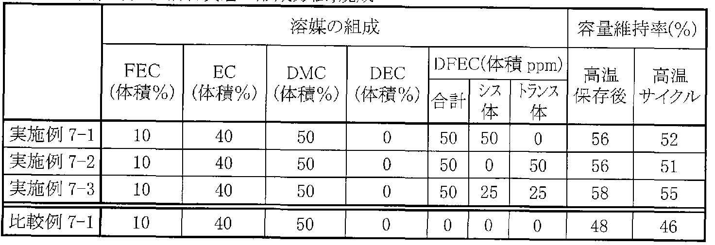
- Examples 7-1 to 7-3 90% by mass of an average particle diameter of 1 ⁇ m of silicon powder and 10% by mass of polyvinylidene fluoride as a binder are N— Disperse in methyl-2-pyrrolidone, apply it to the negative electrode current collector 52A made of 18 m thick electrolytic copper foil, dry, pressurize, and heat-treat at 400 ° C for 12 hours in a vacuum atmosphere. Thus, a negative electrode active material layer 52B was formed, and a negative electrode 52 was produced.
- FEC 4-full-year-old 1,3-shi kid nolan-2-one EC; ethylene carbonate DMC; carbonated y; ⁇ chi) DEC; cetyl carbonate DFEC; B-1,3-Shiokiriran—2 years old
- Table 5-7 Examples 5—! 5— 3, 6—:! 6— 3, 7— :!
- a secondary battery was fabricated in the same manner as in Examples 1-1 to 1-24, except that artificial graphite powder was used as the negative electrode active material, and the negative electrode 52 was fabricated.
- Solvents in the electrolyte include 4 fluoro 1,3 dioxolane 2 on, ethylene carbonate, dimethyl carbonate, ethyl carbonate (MEC), vinylene carbonate (VC), 4, 5 difluoro 1, 3 Dioxolane and 1-on were prepared, and their contents were changed as shown in Table 8. Further, as Comparative Examples 8-1 to 8-3 with respect to Examples 8-1 to 8-9, 4,5 difluoro-1,3 dixolan-2-one was not added, and the composition of the solvent is shown in Table 8.
- a secondary battery was fabricated in the same manner as in Example 8— :! to 8-9 except for the above changes.
- Example 8 For the secondary batteries of Example 8::! To 8-9 and Comparative Example 8-1 to 8-3, a charge / discharge test was conducted in the same manner as in Example 1-1 to 1-2-24. High temperature storage characteristics and high temperature cycle characteristics were investigated. The results are shown in Table 8.
- Negative electrode active material Artificial graphite, formation method of negative electrode active material layer; coating
- a lithium metal secondary battery in which the capacity of the negative electrode is represented by the capacity component due to precipitation and dissolution of lithium was produced.
- the shape of the battery is a coin type as shown in FIG. 5, except that a metal lithium plate having a thickness of lmm is punched into a circular shape with a diameter of 16 mm to form a negative electrode 52.
- Examples 1-15 to 1-17 Same as above.
- Comparative Example 9-1 with respect to Examples 9-1 to 9-3, except that 4,5 difunoleoro 1,3 dixolan-2-one was not added the other cases were the same as in Examples 9 1 to 93 except that secondary A battery was produced.
- a secondary battery in which the capacity of the negative electrode includes a capacity component due to insertion and extraction of lithium and a capacity component due to precipitation and dissolution of lithium and is expressed by the sum thereof was produced.
- the shape of the battery is a coin type as shown in FIG. 5, and the negative electrode 52 is manufactured using artificial graphite powder as the negative electrode active material, and the charge capacity of the artificial graphite is made smaller than the charge capacity of the positive electrode 51.
- the other procedures were the same as those in Examples 1-15 to 1-17 except that the amount of the artificial graphite powder was adjusted so that lithium metal was deposited on the negative electrode 52 during the charging.
- Example 10-1 to LO A secondary battery was fabricated in the same manner as in 3.
- Example 10-1 ⁇ Secondary batteries of LO-3 and Comparative Example 10-1 were also subjected to charge / discharge tests in the same manner as in Example 1-1-5 to 1-17, and were subjected to high-temperature storage characteristics. And the high temperature cycle characteristics were investigated. The results are shown in Table 10.
- Negative electrode active material graphite + u metal, formation method of negative electrode active material layer; coating
- Example 10-1 According to LO-3, as with Examples 1-15-15-17, compared to Comparative Example 10-1 As a result, both high-temperature storage characteristics and high-temperature cycle characteristics could be improved.
- the capacity of the negative electrode includes a capacity component due to insertion and extraction of lithium and a capacity component due to precipitation and dissolution of lithium, and is expressed as a sum thereof, 4, 5 difluoro- 1 , 3 Dioxolan 2— It was found that high temperature characteristics could be improved if ON was included.
- the cylindrical secondary battery shown in Figs. 1 and 2 was fabricated.
- the positive electrode 21 was produced in the same manner as in Examples 1-1 to 1-24.
- the negative electrode 22 was prepared in the same manner as in Examples 1-1 to 1-24 in Examples 11-1 to L-1-5 and in Examples 2-1 to 1-2-6 in Examples 12-1 to 12-6.
- Examples 13-1 to 13-6 they were prepared in the same manner as in Examples 7-1 to 7-3. That is, in Examples 11-1 to 11-5, a copper / tin alloy powder was used as the negative electrode active material, and the negative electrode active material layer 22B was formed by coating.
- the negative electrode active material layer 22B was formed by electron beam evaporation using silicon as the negative electrode active material.
- the cathode powder was used as the negative electrode active material, and the negative electrode active material layer 22B was formed by a firing method.
- the amount of charge was adjusted so that the charge capacity of copper'tin alloy or silicon was larger than the charge capacity of the positive electrode 21, so that lithium metal was not deposited on the negative electrode 22 during the charge. That is, it was set as the lithium ion secondary battery similarly to Example 1-1-1-24, 2-1-2-23, 7-1-73.
- a microporous polypropylene film having a thickness of 25 ⁇ m was used for the separator 23, and the size was 14 mm in diameter and 65 mm in height.
- the electrolyte contains LiPF as an electrolyte salt in a solvent whose composition has changed.
- the composition of the solvent was changed as shown in Tables 11 to 13 without adding 4,5 difluoro-1,3 dixolan-2-one.
- secondary batteries were fabricated in the same manner as in Examples 11-1 to L 1-5, 12-1 to 12-6, 13-1 to 13-6.
- FEC 4-Fluoro D- 1,3-Choxylan-2-one EC; Ethylene carbonate DMC; Carbonate; (Til DEC; Carbonate 'I Til DFEC; 4,5-/ "Fluoro 1, 3-Si 'Oki' Nolan-2 On
- Negative electrode active material Si, formation method of negative electrode active material layer; electron beam
- FEC 4-7) Wn-l, 3-year-old Kirilla>-2-one EC; ethylene carbonate DMC; carbonated meth ft DEC; carbonated cetyl DFEC; 4,5-sylfluoro-1,3— Shi "-year-old Kiririran 2-on
- a secondary battery was fabricated in the same manner as in Examples 11-1 to 11:15 except that the anode 22 was fabricated using artificial graphite powder as the anode active material.
- Solvents include 4-1-fluoro-1,3-dioxolane-2-one, ethylene carbonate, dimethyl carbonate, ethylmethyl carbonate, vinylene carbonate, and 45-difluoro-1,3-dioxolane-2-one. Then, their contents were changed as shown in Table 14. In addition, as Comparative Example 14- :!
- Example 14-4 for Example 14-1 14-15 4, 5-difluoro-1,3-dioxolan-2-one was not added, and the solvent composition was changed to Table 14
- a secondary battery was fabricated in the same manner as in Example 1-4-1-14-5 except that the changes were made as shown in FIG.
- FEC 4 -full-year D-l, 3-shiran 2-on EC; ethylene carbonate DV; methyl carbonate
- the laminated film type secondary battery shown in FIGS. 3 and 4 was produced.
- the positive electrode 33 was produced in the same manner as in Examples 1-1 to 1-24.
- a negative electrode 34 was produced by forming a negative electrode active material layer 34B made of silicon by electron beam evaporation in the same manner as in Examples 2-1 to 2-33.
- the amount of the potassium was adjusted so that the charge capacity of the cathode was larger than the charge capacity of the positive electrode 33 so that the lithium metal was not deposited on the negative electrode 34 during the charge. That is, it was set as the lithium ion secondary battery like Example 1-1-1-24, 2-1-2-23.
- PVDF polyvinylidene fluoride
- HFP hexafluoropropylene
- this precursor solution was applied to both surfaces of the positive electrode 33 and the negative electrode 34, and the mixed solution was volatilized.
- the positive electrode lead 31 made of aluminum is attached to the positive electrode 33
- the negative electrode lead 32 made of nickel is attached to the negative electrode 34
- the positive electrode 33 and the negative electrode 34 are separated by a separator made of a microporous polyethylene film having a thickness of 25 ⁇ m.
- the outer member 40 made of a laminate film was sealed under reduced pressure.
- dimethyl carbonate was added to the inside of the exterior member 40 before the exterior member 40 was sealed.
- Example 15-1 As Comparative Example 15-1 to Examples 15-1 to 15-6, except that 4,5 difluoro 1,3 dioxolan-2-one was not added, the same as Example 15-1 except that Thus, a secondary battery was produced.
- Negative electrode active material Si, formation method of negative electrode active material layer: electron beam
- a secondary battery was fabricated in the same manner as in Examples 1-1 to 1-124 except that a CoSnC-containing material was used as the negative electrode active material.
- the CoSnC-containing material was synthesized using a mechanochemical reaction by mixing tin 'cono-colt'indium' titanium alloy powder and carbon powder.
- the resulting CoSnC-containing material was analyzed for composition, and the tin content was 48 masses. / 0 , the cobalt content was 23% by mass, and the carbon content was 20% by mass.
- the negative electrode 52 was prepared by mixing 80 parts by mass of the CoSnC-containing material, 11 parts by mass of graphite and 1 part by mass of acetylene black as a conductive agent, and 8 parts by mass of polyvinylidene fluoride as a binder. It was formed by dispersing and coating in N-methyl-2-pyrrolidone.
- the solvent of the electrolyte includes 4 monofluoro-1,3-dioxolan-2-one, ethylene carbonate, propylene carbonate, dimethyl carbonate, ethyl methyl carbonate, jetyl carbonate, 4, 5— Difluoro-1,1,3-oxolan-2-one were prepared, and their contents were changed as shown in Table 16.
- the composition of the solvent is expressed in units of mass. Represents.
- Examples 16-1 to 16-19 Rechargeable batteries of Comparative Examples 16-1 to 16-4 were also charged in the same manner as in Examples 1-1 to 1-24.
- a discharge test was conducted to investigate high-temperature storage characteristics and high-temperature site characteristics. Also, as room temperature cycle characteristics, charge / discharge was repeated 100 cycles at 23 ° C, and the ratio of the discharge capacity at the 100th cycle to the discharge capacity at the 2nd cycle, that is, the discharge capacity at the 100th cycle Z2 discharge at the 2nd cycle Capacity) X 100 was determined.
- the charging / discharging conditions are the same as those described in Examples 1-1 to 1-24. The results obtained are shown in Table 16.
- FEC 4-Fluoro- 0- 1,3-Chisolan-2-one EC; Ethylene carbonate PC: Carbonic acid D-pyrene DMC; Carbonyl carbonate EMC; Ethyl carbonate) Resyl Carbonate DFEC; 4, 5-Si'Fluo Q-1,3
- the negative electrode active material layer 52B is formed by electron beam evaporation.
- a secondary battery was fabricated in the same manner as in Examples 1-1 to 1-24, except for the formation. At that time, the composition of the solvent in the electrolytic solution was changed as shown in Table 17 in Examples 17-1 to 17-19. In this example, the composition of the solvent is expressed in terms of mass. In addition, it is compared with the implementation f row 17-1 to 17-19 as f row 17-1 to 17-4, and 4, 5-difunoleo 1,3-dioxolan-2-one is not added, and the composition of the solvent is changed.
- a secondary battery was fabricated in the same manner as in Examples 17-1 to 17-19 except that the changes were made as shown in Table 17.
- Negative electrode active material Si, formation method of negative electrode active material layer: electron beam
- the amount is preferably within the range of 5% by mass or more and 50% by mass or less.
- Example 18— 1 18— 19 In the same manner as in Examples 9 1 to 93, a lithium metal secondary battery in which the capacity of the negative electrode was expressed by a capacity component due to precipitation and dissolution of lithium was produced.
- the composition of the solvent in the electrolytic solution was changed as shown in Table 18 in Examples 18-1 to 18-19. In this example, the composition of the solvent is expressed in units of mass.
- Comparative Examples 18-1 to 18-4 for Examples 18-1 to 18-19 4, 5 difluoro-1,3 dioxolan-2-one was not added, and the solvent composition is shown in Table 18.
- a secondary battery was fabricated in the same manner as in Examples 18-1 to 18-19 except for the change as shown.
- Examples 18-1 to 18-19 Rechargeable batteries of Comparative Examples 18-1 to 18-4 were also charged in the same manner as in Examples 1-1 to 1-24.
- a discharge test was conducted to investigate high-temperature storage characteristics and high-temperature site characteristics.
- the room temperature cycle characteristics were also examined in the same manner as in Examples 16-1 to 16-19. The results are shown in Table 18.
- Example 1 1 1 1
- a secondary battery was fabricated in the same manner as 24. At that time, the composition of the solvent in the electrolytic solution was changed as shown in Table 19 in Examples 19-1 19-4. In this example, the composition of the solvent is expressed in units of mass. In addition, as Comparative Example 19-1 19-2 for Example 19-1 19-4, 4,5-difluoro-13-dioxolan-2-one was not added and the composition of the solvent is shown in Table 19. A secondary battery was fabricated in the same manner as in Examples 19-1 19-4 except that the change was made as described above.
- Example 19 1 1 19 1 4 and Comparative Example 19-1 and 19 1 charge / discharge tests were conducted in the same manner as in Example 1-1 1 19 24, and high temperature storage characteristics were obtained. And the high-temperature cycle characteristics were investigated. In addition, the room temperature cycle characteristics were also examined in the same manner as in Examples 16-1 to L6-19. The results are shown in Table 19.
- Example 19-1 1 19—4 4-full-year-old -1- 3-year-old xoxolan-2-one EC; ethylene carbonate PC; carbonated carbon. Propylene DEC; shetilt carbonate DFEC; 4,5-fluoro-1 3_shixolan-2- As shown in Table 19, according to Example 19-1 1 19—4, 4, 5-difluoro-1,3-dioxolan-2-one was added. Compared with 1, 19-2, room temperature cycle characteristics, high temperature storage characteristics, and high temperature cycle characteristics were improved. However, the degree of improvement is shown in Examples 16-1 16-19, 17-1 17-19, and the negative electrode active material using a material containing tin or silicon as a constituent element as the negative electrode active material. Compared to Examples 18-1 18-19 using lithium metal, the strength was lower. [0153] (Example 20-1)
- Example 15-1 The laminated film type secondary battery shown in FIGS. 3 and 4 was produced in the same manner as 15-6.
- the composition of the solvent in the electrolytic solution was changed as shown in Table 20. In this example, the composition of the solvent is expressed in terms of mass.
- Comparative Example 20-1 with respect to Example 20-0-1 4-Fluoro-13-dioxolan-2-one was used instead of 4,5-Difluoro-1,3-dioxolan-2-one. Except for this, a secondary battery was fabricated in the same manner as in Example 20-1.
- Example 20-1 and Comparative Example 20-1 were also subjected to charge / discharge tests in the same manner as in Examples 15-1 15-6 to examine high-temperature storage characteristics and high-temperature cycle characteristics. .
- charging / discharging was repeated 100 cycles at 23 ° C under the conditions described in Example 15- :! 15-6, and the ratio of the discharge capacity at the 100th cycle to the discharge capacity at the second cycle was determined as the room temperature cycle characteristics. .
- the results obtained are shown in Table 20.
- Example 20-1 room temperature cycle characteristics, high temperature storage characteristics, and high temperature cycle characteristics could be improved as compared with Comparative Example 20-1. That is, even when the electrolytic solution is held in a polymer compound to form a gel electrolyte, the content of 4,5-difluoro-1,3-dioxolan-2-one is in the range of 5 mass% to 50 mass%. It turned out to be preferable if it is in the inside.
- the force described for the battery using lithium as the electrode reactant is another alkali metal such as sodium (Na) or potassium (K), or magnesium or calcium.
- the present invention can also be applied to the case of using an alkaline earth metal such as (Ca) or another light metal such as aluminum.
- the negative electrode active material for example, the same materials as those in the above embodiment can be used.
- a secondary battery using an external member such as a cylindrical secondary battery and a laminate film will be specifically described.
- a coin-type secondary battery is described.
- the Power Described for the Battery The present invention can be similarly applied to a secondary battery having another shape such as a button type or a square type, or a secondary battery having another structure such as a laminated structure. Further, the present invention is not limited to the secondary battery but can be similarly applied to other batteries such as a primary battery.
Landscapes
- Chemical & Material Sciences (AREA)
- General Chemical & Material Sciences (AREA)
- Chemical Kinetics & Catalysis (AREA)
- Electrochemistry (AREA)
- Engineering & Computer Science (AREA)
- Manufacturing & Machinery (AREA)
- Inorganic Chemistry (AREA)
- Physics & Mathematics (AREA)
- Condensed Matter Physics & Semiconductors (AREA)
- General Physics & Mathematics (AREA)
- Materials Engineering (AREA)
- Secondary Cells (AREA)
- Battery Electrode And Active Subsutance (AREA)
- Primary Cells (AREA)
Abstract
Description




Claims
Priority Applications (4)
| Application Number | Priority Date | Filing Date | Title |
|---|---|---|---|
| KR1020077006419A KR101283180B1 (ko) | 2004-09-22 | 2005-09-21 | 전해액 및 전지 |
| JP2006536398A JP5103903B2 (ja) | 2004-09-22 | 2005-09-21 | 二次電池用電解液および二次電池 |
| US11/575,533 US8715864B2 (en) | 2004-09-22 | 2005-09-21 | Electrolytic solution and battery |
| US14/177,718 US9548516B2 (en) | 2004-09-22 | 2014-02-11 | Electrolytic solution and battery |
Applications Claiming Priority (2)
| Application Number | Priority Date | Filing Date | Title |
|---|---|---|---|
| JP2004-274796 | 2004-09-22 | ||
| JP2004274796 | 2004-09-22 |
Related Child Applications (2)
| Application Number | Title | Priority Date | Filing Date |
|---|---|---|---|
| US11/575,533 A-371-Of-International US8715864B2 (en) | 2004-09-22 | 2005-09-21 | Electrolytic solution and battery |
| US14/177,718 Continuation US9548516B2 (en) | 2004-09-22 | 2014-02-11 | Electrolytic solution and battery |
Publications (1)
| Publication Number | Publication Date |
|---|---|
| WO2006033358A1 true WO2006033358A1 (ja) | 2006-03-30 |
Family
ID=36090115
Family Applications (1)
| Application Number | Title | Priority Date | Filing Date |
|---|---|---|---|
| PCT/JP2005/017397 Ceased WO2006033358A1 (ja) | 2004-09-22 | 2005-09-21 | 電解液および電池 |
Country Status (6)
| Country | Link |
|---|---|
| US (2) | US8715864B2 (ja) |
| JP (2) | JP5103903B2 (ja) |
| KR (1) | KR101283180B1 (ja) |
| CN (1) | CN100502136C (ja) |
| TW (1) | TWI275195B (ja) |
| WO (1) | WO2006033358A1 (ja) |
Cited By (14)
| Publication number | Priority date | Publication date | Assignee | Title |
|---|---|---|---|---|
| WO2007136046A1 (ja) * | 2006-05-23 | 2007-11-29 | Sony Corporation | 負極およびその製造方法、ならびに電池およびその製造方法 |
| JP2008004535A (ja) * | 2006-05-23 | 2008-01-10 | Sony Corp | 負極および電池 |
| JP2008010414A (ja) * | 2006-06-02 | 2008-01-17 | Mitsubishi Chemicals Corp | 非水系電解液及び非水系電解液電池 |
| JP2008016422A (ja) * | 2006-06-07 | 2008-01-24 | Sony Corp | 電解質およびこれを用いた電池、並びに角型電池用電解質およびこれを用いた角型電池 |
| JP2008034334A (ja) * | 2006-06-28 | 2008-02-14 | Sony Corp | 電池 |
| JP2009032653A (ja) * | 2007-06-28 | 2009-02-12 | Mitsubishi Chemicals Corp | 二次電池用非水系電解液及びそれを用いた非水系電解液二次電池 |
| JP2009123424A (ja) * | 2007-11-13 | 2009-06-04 | Sony Corp | 非水電解質二次電池 |
| JP2010034087A (ja) * | 2009-11-16 | 2010-02-12 | Sony Corp | リチウムイオン二次電池 |
| JP2011054406A (ja) * | 2009-09-01 | 2011-03-17 | Mitsui Chemicals Inc | 非水電解液及びそれを用いた非水電解質二次電池 |
| CN102593528A (zh) * | 2006-10-13 | 2012-07-18 | 索尼株式会社 | 电池 |
| JP2013080727A (ja) * | 2006-06-02 | 2013-05-02 | Mitsubishi Chemicals Corp | 非水系電解液及び非水系電解液電池 |
| KR101369537B1 (ko) * | 2006-03-22 | 2014-03-04 | 소니 주식회사 | 리튬 이온 이차 전지용 전해액 및 리튬 이온 이차 전지 |
| JP2021082556A (ja) * | 2019-11-22 | 2021-05-27 | 三菱ケミカル株式会社 | 非水系電解液及びエネルギーデバイス |
| JP2022105193A (ja) * | 2014-03-24 | 2022-07-12 | 株式会社半導体エネルギー研究所 | リチウムイオン二次電池 |
Families Citing this family (7)
| Publication number | Priority date | Publication date | Assignee | Title |
|---|---|---|---|---|
| US20080241703A1 (en) * | 2007-03-28 | 2008-10-02 | Hidekazu Yamamoto | Nonaqueous electrolyte secondary battery |
| KR100918387B1 (ko) * | 2007-09-06 | 2009-09-24 | 한국전자통신연구원 | 고속 충전 및 고출력 방전 소자용 액체 전해질 조성물의설계 방법 |
| KR100988657B1 (ko) * | 2008-05-21 | 2010-10-18 | 삼성에스디아이 주식회사 | 리튬이온 이차전지용 전해액 및 이를 포함하는 리튬이온이차전지 |
| US10590789B2 (en) | 2017-04-26 | 2020-03-17 | Borgwarner Inc. | Turbocharger radial seal |
| US10868306B2 (en) | 2017-05-19 | 2020-12-15 | Sion Power Corporation | Passivating agents for electrochemical cells |
| JP7210475B2 (ja) | 2017-05-19 | 2023-01-23 | シオン・パワー・コーポレーション | 電気化学セルの不動態化剤 |
| US12388115B2 (en) * | 2019-01-08 | 2025-08-12 | Tesla, Inc. | Electrolytes with lithium difluoro(oxalato)borate and lithium tetrafluoroborate salts for lithium metal and anode-free cells |
Citations (6)
| Publication number | Priority date | Publication date | Assignee | Title |
|---|---|---|---|---|
| JPH05325985A (ja) * | 1992-05-15 | 1993-12-10 | Sanyo Electric Co Ltd | 非水系電解液電池 |
| JPH07240232A (ja) * | 1994-01-07 | 1995-09-12 | Sony Corp | 非水電解液二次電池 |
| JPH10189043A (ja) * | 1996-12-26 | 1998-07-21 | Hitachi Ltd | リチウム2次電池 |
| JP2003168480A (ja) * | 2001-12-04 | 2003-06-13 | Hitachi Ltd | リチウム二次電池とその電解液及びその正極 |
| JP2004171875A (ja) * | 2002-11-19 | 2004-06-17 | Sony Corp | 負極およびそれを用いた電池 |
| JP2004319317A (ja) * | 2003-04-17 | 2004-11-11 | Hitachi Maxell Ltd | リチウム二次電池 |
Family Cites Families (7)
| Publication number | Priority date | Publication date | Assignee | Title |
|---|---|---|---|---|
| US4431786A (en) * | 1982-05-06 | 1984-02-14 | E. I. Du Pont De Nemours And Company | Novel fluorodioxoles and fluorodioxole polymers |
| US5750730A (en) * | 1996-01-10 | 1998-05-12 | Sanyo Chemical Industries, Ltd. | Fluorine-containing dioxolane compound, electrolytic solution composition, battery and capacitor |
| JP2000223368A (ja) | 1999-02-01 | 2000-08-11 | Asahi Glass Co Ltd | 二次電源 |
| JP2001093572A (ja) * | 1999-09-27 | 2001-04-06 | Hitachi Ltd | 非水電解液二次電池及びそれを用いた電気自動車、ハイブリット式自動車及び電力貯蔵システム |
| JP2002175837A (ja) * | 2000-12-06 | 2002-06-21 | Nisshinbo Ind Inc | 高分子ゲル電解質及び二次電池並びに電気二重層キャパシタ |
| KR100382767B1 (ko) * | 2001-08-25 | 2003-05-09 | 삼성에스디아이 주식회사 | 리튬 2차 전지용 음극 박막 및 그의 제조방법 |
| JP4442235B2 (ja) * | 2004-01-28 | 2010-03-31 | ソニー株式会社 | 二次電池用負極、二次電池およびそれらの製造方法 |
-
2005
- 2005-09-21 JP JP2006536398A patent/JP5103903B2/ja not_active Expired - Lifetime
- 2005-09-21 KR KR1020077006419A patent/KR101283180B1/ko not_active Expired - Lifetime
- 2005-09-21 US US11/575,533 patent/US8715864B2/en active Active
- 2005-09-21 WO PCT/JP2005/017397 patent/WO2006033358A1/ja not_active Ceased
- 2005-09-21 CN CNB2005800392257A patent/CN100502136C/zh not_active Expired - Lifetime
- 2005-09-22 TW TW094132864A patent/TWI275195B/zh not_active IP Right Cessation
-
2011
- 2011-09-16 JP JP2011202777A patent/JP5660326B2/ja not_active Expired - Lifetime
-
2014
- 2014-02-11 US US14/177,718 patent/US9548516B2/en not_active Expired - Lifetime
Patent Citations (6)
| Publication number | Priority date | Publication date | Assignee | Title |
|---|---|---|---|---|
| JPH05325985A (ja) * | 1992-05-15 | 1993-12-10 | Sanyo Electric Co Ltd | 非水系電解液電池 |
| JPH07240232A (ja) * | 1994-01-07 | 1995-09-12 | Sony Corp | 非水電解液二次電池 |
| JPH10189043A (ja) * | 1996-12-26 | 1998-07-21 | Hitachi Ltd | リチウム2次電池 |
| JP2003168480A (ja) * | 2001-12-04 | 2003-06-13 | Hitachi Ltd | リチウム二次電池とその電解液及びその正極 |
| JP2004171875A (ja) * | 2002-11-19 | 2004-06-17 | Sony Corp | 負極およびそれを用いた電池 |
| JP2004319317A (ja) * | 2003-04-17 | 2004-11-11 | Hitachi Maxell Ltd | リチウム二次電池 |
Cited By (27)
| Publication number | Priority date | Publication date | Assignee | Title |
|---|---|---|---|---|
| KR101369537B1 (ko) * | 2006-03-22 | 2014-03-04 | 소니 주식회사 | 리튬 이온 이차 전지용 전해액 및 리튬 이온 이차 전지 |
| US8679683B2 (en) * | 2006-03-22 | 2014-03-25 | Sony Corporation | Electrolyte solution containing a cyclic imide salt and light metal salt and battery |
| US9431650B2 (en) | 2006-05-23 | 2016-08-30 | Sony Corporation | Method of manufacturing anode active material with oxide coating on active particles |
| JP2008004535A (ja) * | 2006-05-23 | 2008-01-10 | Sony Corp | 負極および電池 |
| US9166221B2 (en) | 2006-05-23 | 2015-10-20 | Sony Corporation | Anode and battery with improved charge-discharge efficiency and method manufacturing the same |
| US10205163B2 (en) | 2006-05-23 | 2019-02-12 | Murata Manufacturing Co., Ltd. | Battery with anode active material with oxide coating on active particles |
| WO2007136046A1 (ja) * | 2006-05-23 | 2007-11-29 | Sony Corporation | 負極およびその製造方法、ならびに電池およびその製造方法 |
| US8932761B2 (en) | 2006-05-23 | 2015-01-13 | Sony Corporation | Anode and method of manufacturing the same, and battery and method of manufacturing the same |
| US9231276B2 (en) | 2006-06-02 | 2016-01-05 | Mitsubishi Chemical Corporation | Nonaqueous electrolytic solutions and nonaqueous-electrolyte batteries |
| JP2013080727A (ja) * | 2006-06-02 | 2013-05-02 | Mitsubishi Chemicals Corp | 非水系電解液及び非水系電解液電池 |
| JP2008010414A (ja) * | 2006-06-02 | 2008-01-17 | Mitsubishi Chemicals Corp | 非水系電解液及び非水系電解液電池 |
| JP2008016422A (ja) * | 2006-06-07 | 2008-01-24 | Sony Corp | 電解質およびこれを用いた電池、並びに角型電池用電解質およびこれを用いた角型電池 |
| JP2008034334A (ja) * | 2006-06-28 | 2008-02-14 | Sony Corp | 電池 |
| CN102593528A (zh) * | 2006-10-13 | 2012-07-18 | 索尼株式会社 | 电池 |
| US9196927B2 (en) | 2006-10-13 | 2015-11-24 | Sony Corporation | Battery including an electrolytic solution containing a sulfone compound |
| JP2009032653A (ja) * | 2007-06-28 | 2009-02-12 | Mitsubishi Chemicals Corp | 二次電池用非水系電解液及びそれを用いた非水系電解液二次電池 |
| US9831532B2 (en) | 2007-11-13 | 2017-11-28 | Sony Corporation | Nonaqueous electrolyte secondary battery |
| US9647298B2 (en) | 2007-11-13 | 2017-05-09 | Sony Corporation | Nonaqueous electrolyte battery and electrical apparatus |
| US8609286B2 (en) | 2007-11-13 | 2013-12-17 | Sony Corporation | Nonaqueous electrolyte secondary battery |
| JP2009123424A (ja) * | 2007-11-13 | 2009-06-04 | Sony Corp | 非水電解質二次電池 |
| US10707539B2 (en) | 2007-11-13 | 2020-07-07 | Murata Manufacturing Co., Ltd. | Battery |
| JP2011054406A (ja) * | 2009-09-01 | 2011-03-17 | Mitsui Chemicals Inc | 非水電解液及びそれを用いた非水電解質二次電池 |
| JP2010034087A (ja) * | 2009-11-16 | 2010-02-12 | Sony Corp | リチウムイオン二次電池 |
| JP2022105193A (ja) * | 2014-03-24 | 2022-07-12 | 株式会社半導体エネルギー研究所 | リチウムイオン二次電池 |
| JP2025015698A (ja) * | 2014-03-24 | 2025-01-30 | 株式会社半導体エネルギー研究所 | リチウムイオン二次電池 |
| JP2021082556A (ja) * | 2019-11-22 | 2021-05-27 | 三菱ケミカル株式会社 | 非水系電解液及びエネルギーデバイス |
| JP7300373B2 (ja) | 2019-11-22 | 2023-06-29 | 三菱ケミカル株式会社 | 非水系電解液及びエネルギーデバイス |
Also Published As
| Publication number | Publication date |
|---|---|
| KR20070055549A (ko) | 2007-05-30 |
| JP2011258582A (ja) | 2011-12-22 |
| TW200627689A (en) | 2006-08-01 |
| JP5103903B2 (ja) | 2012-12-19 |
| JP5660326B2 (ja) | 2015-01-28 |
| US20140162142A1 (en) | 2014-06-12 |
| JPWO2006033358A1 (ja) | 2008-05-15 |
| CN101061599A (zh) | 2007-10-24 |
| CN100502136C (zh) | 2009-06-17 |
| KR101283180B1 (ko) | 2013-07-05 |
| US9548516B2 (en) | 2017-01-17 |
| US8715864B2 (en) | 2014-05-06 |
| US20080063946A1 (en) | 2008-03-13 |
| TWI275195B (en) | 2007-03-01 |
Similar Documents
| Publication | Publication Date | Title |
|---|---|---|
| JP5660326B2 (ja) | 二次電池 | |
| JP4984022B2 (ja) | 二次電池 | |
| JP4544270B2 (ja) | 二次電池用電解液および二次電池 | |
| JP5067522B2 (ja) | 二次電池用電解液および二次電池 | |
| JP5229527B2 (ja) | 二次電池用電解液および二次電池 | |
| JP4329806B2 (ja) | 二次電池 | |
| JP4940625B2 (ja) | 電解液および電池 | |
| KR20060107397A (ko) | 전지 | |
| KR101251640B1 (ko) | 부극 활성 물질 및 그것을 사용한 전지 | |
| JP4836767B2 (ja) | リチウムイオン二次電池 | |
| JP5201364B2 (ja) | 二次電池用電解液および二次電池 | |
| JP4957944B2 (ja) | 二次電池 | |
| JP4792919B2 (ja) | 電池 | |
| JP4951933B2 (ja) | リチウムイオン二次電池用電解質およびリチウムイオン二次電池 | |
| JP2007042387A (ja) | 電解液,電極および電池 | |
| JP2008293687A (ja) | 電解液および電池 | |
| JP2006331866A (ja) | 電池 | |
| JP2007273396A (ja) | 電解液および電池 | |
| JP2008053054A (ja) | 電池 | |
| JP2007242545A (ja) | 電解質および電池 | |
| JP4940570B2 (ja) | リチウム二次電池用電解液およびリチウム二次電池 | |
| JP5076280B2 (ja) | 非水二次電池用電解液および非水二次電池 | |
| JP2007157399A (ja) | 電解液および電池 | |
| JP2008147118A (ja) | 電池 | |
| JP2012009460A (ja) | 電解液および二次電池 |
Legal Events
| Date | Code | Title | Description |
|---|---|---|---|
| AK | Designated states |
Kind code of ref document: A1 Designated state(s): AE AG AL AM AT AU AZ BA BB BG BR BW BY BZ CA CH CN CO CR CU CZ DE DK DM DZ EC EE EG ES FI GB GD GE GH GM HR HU ID IL IN IS JP KE KG KM KP KR KZ LC LK LR LS LT LU LV LY MA MD MG MK MN MW MX MZ NA NG NI NO NZ OM PG PH PL PT RO RU SC SD SE SG SK SL SM SY TJ TM TN TR TT TZ UA UG US UZ VC VN YU ZA ZM ZW |
|
| AL | Designated countries for regional patents |
Kind code of ref document: A1 Designated state(s): BW GH GM KE LS MW MZ NA SD SL SZ TZ UG ZM ZW AM AZ BY KG KZ MD RU TJ TM AT BE BG CH CY CZ DE DK EE ES FI FR GB GR HU IE IS IT LT LU LV MC NL PL PT RO SE SI SK TR BF BJ CF CG CI CM GA GN GQ GW ML MR NE SN TD TG |
|
| 121 | Ep: the epo has been informed by wipo that ep was designated in this application | ||
| WWE | Wipo information: entry into national phase |
Ref document number: 2006536398 Country of ref document: JP |
|
| WWE | Wipo information: entry into national phase |
Ref document number: 11575533 Country of ref document: US |
|
| WWE | Wipo information: entry into national phase |
Ref document number: 1020077006419 Country of ref document: KR |
|
| NENP | Non-entry into the national phase |
Ref country code: DE |
|
| WWE | Wipo information: entry into national phase |
Ref document number: 200580039225.7 Country of ref document: CN |
|
| 122 | Ep: pct application non-entry in european phase | ||
| WWP | Wipo information: published in national office |
Ref document number: 11575533 Country of ref document: US |