US8308036B2 - Sheet material feeding apparatus - Google Patents
Sheet material feeding apparatus Download PDFInfo
- Publication number
- US8308036B2 US8308036B2 US12/261,387 US26138708A US8308036B2 US 8308036 B2 US8308036 B2 US 8308036B2 US 26138708 A US26138708 A US 26138708A US 8308036 B2 US8308036 B2 US 8308036B2
- Authority
- US
- United States
- Prior art keywords
- roll
- sub
- sheet material
- cam
- eccentric
- Prior art date
- Legal status (The legal status is an assumption and is not a legal conclusion. Google has not performed a legal analysis and makes no representation as to the accuracy of the status listed.)
- Active, expires
Links
- 239000000463 material Substances 0.000 title claims abstract description 119
- 230000002093 peripheral effect Effects 0.000 claims description 10
- 238000006073 displacement reaction Methods 0.000 description 25
- 239000002184 metal Substances 0.000 description 14
- 238000010276 construction Methods 0.000 description 7
- 238000004080 punching Methods 0.000 description 4
- 230000003247 decreasing effect Effects 0.000 description 2
- 230000000694 effects Effects 0.000 description 2
- 238000000034 method Methods 0.000 description 2
- 230000015572 biosynthetic process Effects 0.000 description 1
- 230000015556 catabolic process Effects 0.000 description 1
- 238000006731 degradation reaction Methods 0.000 description 1
- 238000009499 grossing Methods 0.000 description 1
- 238000004519 manufacturing process Methods 0.000 description 1
- 238000005096 rolling process Methods 0.000 description 1
Images


Classifications
-
- B—PERFORMING OPERATIONS; TRANSPORTING
- B30—PRESSES
- B30B—PRESSES IN GENERAL
- B30B15/00—Details of, or accessories for, presses; Auxiliary measures in connection with pressing
- B30B15/30—Feeding material to presses
-
- B—PERFORMING OPERATIONS; TRANSPORTING
- B21—MECHANICAL METAL-WORKING WITHOUT ESSENTIALLY REMOVING MATERIAL; PUNCHING METAL
- B21C—MANUFACTURE OF METAL SHEETS, WIRE, RODS, TUBES OR PROFILES, OTHERWISE THAN BY ROLLING; AUXILIARY OPERATIONS USED IN CONNECTION WITH METAL-WORKING WITHOUT ESSENTIALLY REMOVING MATERIAL
- B21C47/00—Winding-up, coiling or winding-off metal wire, metal band or other flexible metal material characterised by features relevant to metal processing only
- B21C47/34—Feeding or guiding devices not specially adapted to a particular type of apparatus
-
- B—PERFORMING OPERATIONS; TRANSPORTING
- B21—MECHANICAL METAL-WORKING WITHOUT ESSENTIALLY REMOVING MATERIAL; PUNCHING METAL
- B21D—WORKING OR PROCESSING OF SHEET METAL OR METAL TUBES, RODS OR PROFILES WITHOUT ESSENTIALLY REMOVING MATERIAL; PUNCHING METAL
- B21D43/00—Feeding, positioning or storing devices combined with, or arranged in, or specially adapted for use in connection with, apparatus for working or processing sheet metal, metal tubes or metal profiles; Associations therewith of cutting devices
- B21D43/02—Advancing work in relation to the stroke of the die or tool
- B21D43/04—Advancing work in relation to the stroke of the die or tool by means in mechanical engagement with the work
- B21D43/08—Advancing work in relation to the stroke of the die or tool by means in mechanical engagement with the work by rollers
- B21D43/09—Advancing work in relation to the stroke of the die or tool by means in mechanical engagement with the work by rollers by one or more pairs of rollers for feeding sheet or strip material
-
- B—PERFORMING OPERATIONS; TRANSPORTING
- B23—MACHINE TOOLS; METAL-WORKING NOT OTHERWISE PROVIDED FOR
- B23Q—DETAILS, COMPONENTS, OR ACCESSORIES FOR MACHINE TOOLS, e.g. ARRANGEMENTS FOR COPYING OR CONTROLLING; MACHINE TOOLS IN GENERAL CHARACTERISED BY THE CONSTRUCTION OF PARTICULAR DETAILS OR COMPONENTS; COMBINATIONS OR ASSOCIATIONS OF METAL-WORKING MACHINES, NOT DIRECTED TO A PARTICULAR RESULT
- B23Q7/00—Arrangements for handling work specially combined with or arranged in, or specially adapted for use in connection with, machine tools, e.g. for conveying, loading, positioning, discharging, sorting
-
- B—PERFORMING OPERATIONS; TRANSPORTING
- B65—CONVEYING; PACKING; STORING; HANDLING THIN OR FILAMENTARY MATERIAL
- B65H—HANDLING THIN OR FILAMENTARY MATERIAL, e.g. SHEETS, WEBS, CABLES
- B65H20/00—Advancing webs
- B65H20/02—Advancing webs by friction roller
- B65H20/04—Advancing webs by friction roller to effect step-by-step advancement of web
-
- B—PERFORMING OPERATIONS; TRANSPORTING
- B65—CONVEYING; PACKING; STORING; HANDLING THIN OR FILAMENTARY MATERIAL
- B65H—HANDLING THIN OR FILAMENTARY MATERIAL, e.g. SHEETS, WEBS, CABLES
- B65H2404/00—Parts for transporting or guiding the handled material
- B65H2404/10—Rollers
- B65H2404/14—Roller pairs
- B65H2404/144—Roller pairs with relative movement of the rollers to / from each other
- B65H2404/1442—Tripping arrangements
-
- B—PERFORMING OPERATIONS; TRANSPORTING
- B65—CONVEYING; PACKING; STORING; HANDLING THIN OR FILAMENTARY MATERIAL
- B65H—HANDLING THIN OR FILAMENTARY MATERIAL, e.g. SHEETS, WEBS, CABLES
- B65H2511/00—Dimensions; Position; Numbers; Identification; Occurrences
- B65H2511/20—Location in space
- B65H2511/22—Distance
-
- B—PERFORMING OPERATIONS; TRANSPORTING
- B65—CONVEYING; PACKING; STORING; HANDLING THIN OR FILAMENTARY MATERIAL
- B65H—HANDLING THIN OR FILAMENTARY MATERIAL, e.g. SHEETS, WEBS, CABLES
- B65H2513/00—Dynamic entities; Timing aspects
- B65H2513/50—Timing
- B65H2513/51—Sequence of process
-
- B—PERFORMING OPERATIONS; TRANSPORTING
- B65—CONVEYING; PACKING; STORING; HANDLING THIN OR FILAMENTARY MATERIAL
- B65H—HANDLING THIN OR FILAMENTARY MATERIAL, e.g. SHEETS, WEBS, CABLES
- B65H2701/00—Handled material; Storage means
- B65H2701/10—Handled articles or webs
- B65H2701/17—Nature of material
- B65H2701/173—Metal
Definitions
- the present invention relates to a sheet material feeding apparatus that intermittently feeds a sheet material a predetermined quantity by a predetermined quantity to a press apparatus, and more particularly to a sheet material feeding apparatus suited to feeding of a sheet material, which is used for manufacturing small-sized parts used in information associated equipment such as personal computers, etc., to a press apparatus at high speed with high accuracy.
- sheet material feeding apparatuses comprising a pair of upper and lower rolls that interpose therebetween and feed intermittently a sheet material to a press apparatus, a roll clearance adjusting device that adjusts a clearance between the both rolls according to the thickness of a sheet material, and a release device that temporarily releases a sheet material, having been interposed by the both rolls, just before a sheet material fed to the press apparatus is subjected to press working, the pair of rolls comprising a main roll driven by a drive motor and a sub-roll driven through a sheet material by the main roll (see, for example, U.S. Pat. No. 5,720,421).
- the release device performs the function of temporarily releasing a sheet material in synchronism with the operation of a press apparatus, that is, the sheet-material releasing function. That is, there are some metal mold devices for press apparatuses, in which a pilot pin directed downward is protrusively provided on an upper metal mold and just before the upper metal mold and a lower metal mold are caused to butt against each other to permit press working, the pilot pin is inserted into a positioning hole beforehand formed on a sheet material to enable positioning the sheet material relative to the metal mold device with high accuracy. In order to position the sheet material with the use of the pilot pin, it is required that a sheet material feeding apparatus releases the sheet material from the pair of rolls at the time of positioning. The release device is provided to produce such function.
- the U.S. Pat. No. 5,720,421 describes a construction of the release device, which comprises a wedge member having an inclined surface inclined at a predetermined angle and a follower connected to a sub-roll to engage with the inclined surface of the wedge member and in which the wedge member is moved axially of the sub-roll by a drive device to displace the sub-roll up and down through the follower, thereby generating the sheet-material releasing function.
- the construction having the wedge member and the follower also generates the function of adjusting a clearance between the both rolls according to the thickness of a sheet material, that is, the roll clearance adjusting function.
- the follower engages with the inclined surface, which is inclined at a predetermined angle, and when the wedge member is moved axially of the sub-roll, the follower in engagement with the inclined surface of the wedge member is displaced up and down by a magnitude in proportion to shift of the wedge member and the sub-roll is displaced up and down by a magnitude corresponding to the displacement of the follower. That is, horizontal shift of the wedge member and vertical displacement of the sub-roll are linearly related to each other.
- the roll clearance adjusting function is required to generate a vertical displacement of a sub-roll within the range of 1 mm to 5 mm. Even in such case, it suffices that a vertical displacement of a sub-roll required to generate the sheet-material releasing function be in the order of 0.05 mm to 0.1 mm. In this manner, there is usually a large difference between the range of displacement of a sub-roll required to generate the roll clearance adjusting function and the range of displacement of a sub-roll required to generate the sheet-material releasing function.
- the sheet material feeding apparatus has a feature that the roll clearance adjusting device displaces the main roll up and down to adjust a clearance between the both rolls
- the release device includes a sub-roll guide that rotatably supports the sub-roll and can move up and down together with the sub-roll, a rectilinear cam that is movable axially of the sub-roll, a cam follower mounted to the sub-roll guide to engage with a cam surface of the rectilinear cam, and a control device that moves the rectilinear cam in synchronism with the operation of the press apparatus to move the sub-roll up and down through the cam follower and the sub-roll guide.
- the sheet material feeding apparatus generates a sheet-material releasing function by moving the rectilinear cam in synchronism with the operation of the press apparatus to displace the sub-roll up and down through the cam follower and the sub-roll guide.
- a vertical displacement of the sub-roll corresponding to a vertical displacement of the cam follower is controlled by a shape of a cam surface of the rectilinear cam, with which the cam follower engages. Accordingly, an appropriate design of the shape of the cam surface makes it possible to smooth operations at the start (when the sub-roll begins a vertical displacement) and at the time of stoppage (when the sub-roll stops a vertical displacement).
- the roll clearance adjusting device displaces the main roll up and down to generate the roll clearance adjusting function while the release device displaces the sub-roll up and down to generate the sheet-material releasing function.
- the release device since the release device is configured to generate only the sheet-material releasing function irrespective of the roll clearance adjusting function, it becomes very easy to design the shape of the cam surface of the rectilinear cam so as to preferably generate the sheet-material releasing function, or the like. Also, it is possible to appropriately set conditions to design the roll clearance adjusting device irrespective of the sheet-material releasing function.
- the roll clearance adjusting device comprises an eccentric flange mounted rotatably in a housing of the sheet material feeding apparatus and including a cylindrical-shaped, outer peripheral surface centered on an eccentric axis off-centered relative to an axis of the main roll and a cylindrical-shaped, inner peripheral surface in the coaxial relationship with the axis of the main roll, the both axial ends of the main roll are mounted rotatably in the housing with the eccentric flange therebetween, and the main roll is displaced up and down by rotating the eccentric flange relative to the housing about the eccentric axis.
- an eccentric-flange driving device for rotational driving of the eccentric flange is provided on the eccentric flange.
- the eccentric-flange driving device includes an eccentric-flange drive motor mounted to one axial end of the eccentric flange, a swinging arm mounted to a motor shaft of the eccentric-flange drive motor and provided in a recess on a wall portion of the eccentric flange, and a roller follower provided protrusively at a tip end of the swinging arm to be able to roll and to engage with a guide groove provided on a wall portion of a housing of the sheet material feeding apparatus, and when the motor shaft of the eccentric-flange drive motor is rotationally driven to swing the swinging arm, the eccentric flange is rotated through the roller follower and the guide groove.
- FIG. 1 is an axial, cross sectional view showing a sheet material feeding apparatus according to Embodiment 1 of the invention
- FIG. 2 is a cross sectional view as viewed in an arrow direction II-II in FIG. 1 ;
- FIGS. 3A and 3B are cross sectional views illustrating the operation of a release device of the sheet material feeding apparatus according to Embodiment 1;
- FIG. 4 is a view illustrating a control device that controls the release device
- FIG. 5 is a view illustrating an eccentric flange provided on the sheet material feeding apparatus
- FIGS. 6A , 6 B, and 6 C are views illustrating meritorious effects produced by the use of a rectilinear cam
- FIGS. 7A , 7 B, 7 C, 7 D, 7 E, 7 F, and 7 G are schematic views illustrating the relationship between the feeding action of the sheet material feeding apparatus and the action of a press apparatus;
- FIG. 8 is a cross sectional view showing Embodiment 2 of the invention.
- FIG. 9 is a cross sectional view showing Embodiment 3 of the invention.
- FIG. 10 is a cross sectional view showing Embodiment 4 of the invention.
- FIG. 11 is a right side view of FIG. 10 ;
- FIGS. 12A and 12B are views illustrating a state, in which an eccentric flange is rotated in Embodiment 4.
- FIG. 13 is a cross sectional view showing Embodiment 5 of the invention.
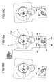
- FIG. 14 is a right side view of FIG. 13 ;
- FIGS. 15A , 15 B, and 15 C are views illustrating the operation of a roll clearance adjusting device in Embodiment 5.
- FIGS. 16A and 16B are cross sectional views showing Embodiment 6 of the invention.
- a sheet material feeding apparatus 1 shown in FIGS. 1 and 2 comprises a pair of upper and lower rolls, that is, a main roll 2 and a sub-roll 3 , by which a sheet material 8 is interposed, and the material is fed to a press apparatus in an intermittent feeding action. While the specific construction of respective parts of the apparatus will be described later, the fundamental operation of the sheet material feeding apparatus 1 will be first described with reference to FIG. 7 .
- FIG. 7A shows a state, in which a punching punch 10 a forms a positioning hole 8 a in the sheet material 8 fed to the press apparatus 9 by the sheet material feeding apparatus 1 (first process), then the sheet material 8 is further fed by the sheet material feeding apparatus 1 , press working, that is, punching working by a blanking punch 10 c (second process) and formation of a positioning hole 8 b by the punching punch 10 a are completed, and a slider 9 a of the press apparatus 9 rises.
- the sheet material feeding apparatus 1 is stationary having the sheet material 8 interposed by the main roll 2 and the sub-roll 3 .
- the main roll 2 is rotationally driven a predetermined angle as shown in FIG. 7B whereby the sub-roll 3 is rotated through the sheet material 8 to feed the sheet material 8 rightward in the figure.
- the sheet material 8 interposed by the both rolls is fed to the press apparatus 9 .
- the both rolls become stationary, at which time the slider 9 a with an upper metal mold 10 A mounted to an underside thereof begins to descend toward a lower metal mold 10 B.
- the sub-roll 3 is displaced downward and the both rolls release the sheet material 8 , in which state the slider 9 a of the press apparatus 9 descends further as shown in FIGS. 7D and 7E and a pilot pin 10 b provided on the upper metal mold 10 A passes through the hole 8 b of the sheet material 8 to be inserted into a receiving hole 10 d of the lower metal mold 10 B.
- the sheet material 8 is positioned highly accurately between the upper metal mold 10 A and the lower metal mold 10 B.
- the slider 9 a descends further, the blanking punch 10 c of the upper metal mold 10 A punches the sheet material 8 , and the punching punch 10 a forms a positioning hole 8 c on the sheet material. Thereafter, as shown in FIG. 7G , the slider 9 a ascends and the sub-roll 3 is displaced upward to bring about a state, in which the both rolls interpose the sheet material 8 .
- the sheet material feeding apparatus 1 intermittently feeds the sheet material 8 to the press apparatus 9 (the upper metal mold 10 A and the lower metal mold 10 B) and the press apparatus 9 performs press working on the sheet material as fed.
- the reference numeral 100 in FIG. 7G denotes a product subjected to press working and 101 denotes punched scrap when the hole 8 c is formed.
- the both rolls release the sheet material temporarily in states shown in FIGS. 7D , 7 E, and 7 F, during which the sheet material is positioned in the press apparatus 9 by inserting the pilot pin 10 b into the hole 8 b beforehand formed on the sheet material.
- a housing of the sheet material feeding apparatus 1 includes a first housing portion 11 accommodating therein the main roll 2 and the eccentric flange 7 and a second housing portion 12 accommodating therein the sub-roll 3 and a sub-roll guide 17 described late in detail.
- the first housing portion 11 and the second housing portion 12 are assembled integrally.
- One end 2 a of the main roll 2 is connected to a motor shaft 6 a of the drive motor 6 , the motor shaft 6 a being mounted rotatably in the eccentric flange 7 with a bearing member 13 therebetween.
- the other end 2 b of the main roll 2 is mounted rotatably in the eccentric flange 7 with a bearing member 14 therebetween.
- Both ends 3 a , 3 b of the sub-roll 3 are supported rotatably on the sub-roll guide 17 with bearing members 15 , 16 therebetween.
- the reference numeral 32 in FIGS. 1 and 2 denotes a sheet material guide.
- a release device 5 comprises the sub-roll guide 17 rotatably supporting the both ends 3 a , 3 b of the sub-roll 3 with the bearing members 15 , 16 therebetween, a rectilinear cam 18 movable axially of the sub-roll 3 , and a control device 24 shown clearly in, especially, FIGS. 3 and 4 .
- the sub-roll guide 17 is accommodated in the second housing portion 12 to be able to move up and down together with the sub-roll 3 and biased downward by elastic members 23 a , 23 b .
- Cam followers 19 , 20 are mounted to a lower end of the sub-roll guide 17 to be able to roll, the cam followers 19 , 20 engaging with cam surfaces 21 , 22 of the rectilinear cam 18 .
- the cam surfaces 21 , 22 are formed in two locations spaced a predetermined distance in a longitudinal direction of the rectilinear cam 18 and the cam followers 19 , 20 engage one by one with the cam surfaces 21 , 22 .
- the control device 24 includes a cylinder 25 provided in the second housing portion 12 and a piston 26 accommodated in the cylinder 25 to be able to reciprocate and connected to the rectilinear cam 18 . Also, formed on the second housing portion 12 are a first port 29 communicated to a portion of the cylinder 25 positioned on one side of the piston 26 and a second port 30 communicated to a portion of the cylinder 25 positioned on the other side of the piston 26 .
- control device 24 responds to a press angle signal from the press apparatus 9 to cause a controller 27 to switch a solenoid 28 , thus controlling supplying of an air to the cylinder 25 from an air source 31 .
- the control device 24 supplies an air to the cylinder 25 through the second port 30 as shown in FIG. 3A to move the rectilinear cam 18 leftward together with the piston 26 and to discharge an air from the cylinder 25 through the first port 29 according to movements thereof. Movements of the rectilinear cam 18 engage the cam followers 19 , 20 with upwardly raised portions of the cam surfaces 21 , 22 of the rectilinear cam 18 . Accordingly, the sub-roll guide 17 and the sub-roll are displaced upward against the elastic forces of the elastic members 23 a , 23 b with the cam followers 19 , 20 therebetween and so the sheet material 8 is interposed between the both rolls.
- the control device 24 supplies an air to the cylinder 25 through the first port 29 as shown in FIG. 3B to move the sheet material 8 rightward together with the piston 26 and to discharge an air from the cylinder 25 through the second port 30 according to movements thereof.
- Movements of the rectilinear cam 18 engage the cam followers 19 , 20 with downwardly dented portions of the cam surfaces 21 , 22 of the rectilinear cam 18 .
- the sub-roll guide 17 and the sub-roll are displaced downward while being pushed downward by the elastic members 23 a , 23 b with the cam followers 19 , 20 therebetween and the sheet material 8 having been interposed between the both rolls is released thereby.
- a roll clearance adjusting device 4 is constructed so that the main roll 2 is displaced up and down to adjust a clearance between the both rolls.
- the roll clearance adjusting device 4 comprises the eccentric flange 7 mounted rotatably in the first housing portion 11 to surround the main roll 2 .
- the both ends 2 a , 2 b of the main roll 2 are mounted in the first housing portion 11 with the bearing members 13 , 14 and the eccentric flange 7 therebetween.
- the eccentric flange 7 includes a cylindrical-shaped, outer peripheral surface 7 A centered on an eccentric axis O′ off-centered relative to an axis O of the main roll 2 by a distance indicated by e in FIG. 5 and a cylindrical-shaped, inner peripheral surface 7 B in the coaxial relationship with the axis O of the main roll 2 .
- the main roll 2 is displaced up and down by a magnitude indicated by ⁇ t whereby it is possible to adjust a clearance C between the both rolls according to the thickness of the sheet material.
- an upper roll comprises the main roll 2 driven by the drive motor and a lower roll comprises the sub-roll 3 but it is of course possible that a lower roll be made a main roll driven by a drive motor and an upper roll be made a sub-roll.
- the roll clearance adjusting device 4 displaces the main roll 2 vertically to generate the roll clearance adjusting function while the release device 5 displaces the sub-roll 3 vertically to generate the sheet-material releasing function.
- the release device since the release device is configured to generate only the sheet-material releasing function irrespective or independently of the roll clearance adjusting function, it becomes very easy to design the shape of the cam surfaces of the rectilinear cam so as to preferably generate the sheet-material releasing function, or the like. Also, it is possible to appropriately set conditions to design the roll clearance adjusting device 4 independently of the release device.
- the sheet-material releasing function can be very readily generated only by using the control device 24 ( FIG. 4 ) to control supply and discharge of an air to the cylinder 25 .
- Embodiments 2 to 6 of the invention will be described below.
- the same elements and members as those in Embodiment 1 are denoted by the same reference numerals in FIGS. 8 to 16 , in which Embodiments 2 to 6 are shown.
- a detailed explanation of the same parts as those in Embodiment 1 is omitted in the following descriptions.
- Embodiment 2 shown in FIG. 8 comprises a single cam surface 21 A formed on a rectilinear cam 18 A and a single cam follower 19 engages with the cam surface 21 A.
- elastic members 40 , 41 are provided in a cylinder 25 .
- the elastic members 40 , 41 are put in a compressed state when a rectilinear cam 18 is in a position shown in FIG. 9 , that is, a sub-roll is displaced upward through the medium of cam followers 19 , 20 and a sub-roll guide 17 to interpose a sheet material between a main roll and the sub-roll. Accordingly, at the time of sheet-material release, at which time the rectilinear cam 18 moves rightward from a position shown in FIG.
- an operating part that is, a projection 50 for rotational operation of an eccentric flange 107 is provided on an end member 60 at one axial end of an eccentric flange 107 .
- Formed on the projection 50 is an arcuate groove 52 centered on an eccentric axis O of the eccentric flange 107 .
- the projection 50 is manually or mechanically grasped and the eccentric flange 107 is rotated. That is, it suffices to rotate the eccentric flange 107 by an appropriate magnitude in a direction, in which a roll clearance is decreased as shown in FIG. 12A , or in a direction, in which a roll clearance is increased as shown in FIG. 12B , and to fix the projection 50 to a housing by means of a bolt 51 .
- an eccentric-flange driving device 54 for rotational driving of an eccentric flange 207 .
- the eccentric-flange driving device 54 includes an eccentric-flange drive motor 53 mounted on an end member 61 at one axial end of the eccentric flange 207 and a swinging arm 57 mounted to a motor shaft 55 of the eccentric-flange drive motor 53 and provided in a recess 56 on a wall portion of the end member 61 of the eccentric flange 207 .
- a roller follower 58 is protrusively provided at a tip end of the swinging arm 57 to be able to roll, the roller follower 58 engaging with a guide groove 59 provided on a wall portion of a housing of a sheet material feeding apparatus, that is, a second housing portion 12 in the embodiment shown in the figure.
- Embodiment 5 when the motor shaft 55 of the eccentric-flange drive motor 53 is rotationally driven from a state shown in FIG. 15A to swing the swinging arm 57 , the roller follower 58 moves up and down in the guide groove 59 while rolling and the swinging arm 57 correspondingly swings together with the motor shaft 55 to rotate the eccentric flange 207 in a direction, in which a roll clearance is decreased as shown in FIG. 15B , or in a direction, in which a roll clearance is increased as shown in FIG. 15C .
- a roll clearance is adjusted without the use of any eccentric flange. That is, according to Embodiment 6, a main roll 2 is held by a holding member 65 provided vertically slidably on a housing 11 A and an adjustment bolt 66 extending through a top wall 11 A′ of the housing to be threaded into the holding member 65 is rotated whereby the main roll 2 together with the holding member 65 is displaced downward as shown in FIG. 16A , or displaced upward as shown in FIG. 16B to adjust a roll clearance according to the thickness of a sheet material.
Applications Claiming Priority (2)
| Application Number | Priority Date | Filing Date | Title |
|---|---|---|---|
| JP2007-283367 | 2007-10-31 | ||
| JP2007283367A JP4429352B2 (ja) | 2007-10-31 | 2007-10-31 | 板材送り装置 |
Publications (2)
| Publication Number | Publication Date |
|---|---|
| US20090108522A1 US20090108522A1 (en) | 2009-04-30 |
| US8308036B2 true US8308036B2 (en) | 2012-11-13 |
Family
ID=40386122
Family Applications (1)
| Application Number | Title | Priority Date | Filing Date |
|---|---|---|---|
| US12/261,387 Active 2030-02-01 US8308036B2 (en) | 2007-10-31 | 2008-10-30 | Sheet material feeding apparatus |
Country Status (7)
| Country | Link |
|---|---|
| US (1) | US8308036B2 (ja) |
| EP (1) | EP2055402B1 (ja) |
| JP (1) | JP4429352B2 (ja) |
| KR (1) | KR101008589B1 (ja) |
| CN (1) | CN101422802B (ja) |
| DE (1) | DE602008001234D1 (ja) |
| TW (1) | TWI371417B (ja) |
Cited By (2)
| Publication number | Priority date | Publication date | Assignee | Title |
|---|---|---|---|---|
| US10118785B2 (en) | 2015-02-23 | 2018-11-06 | Chs Automation | Assembly and process for a press feed mechanism for providing rapid, efficient and tuned hold and release displacement of an upper feed roller relative to a lower roller and between which is communicated a sheet material for subsequent feeding into a press operation |
| US11529667B2 (en) * | 2016-11-22 | 2022-12-20 | Sankyo Seisakusho Co. | Plate material, feeding device |
Families Citing this family (8)
| Publication number | Priority date | Publication date | Assignee | Title |
|---|---|---|---|---|
| CN102189153B (zh) * | 2011-03-09 | 2013-04-10 | 苏州领航自动化科技有限公司 | 一种用于金属板折弯机的压紧装置 |
| JP6166973B2 (ja) * | 2013-07-22 | 2017-07-19 | 株式会社三共製作所 | 板材送り装置 |
| ES2645422T3 (es) * | 2013-09-13 | 2017-12-05 | Tetra Laval Holdings & Finance Sa | Una unidad y un método para llevar a cabo una primera operación y una segunda operación en una banda |
| JP6608635B2 (ja) | 2015-07-13 | 2019-11-20 | 株式会社三共製作所 | 板材送り装置 |
| CA3057823C (en) * | 2017-03-24 | 2022-03-15 | Ranpak Corp. | Dunnage conversion machine having a variable spacing for expandable slit-sheet stock material |
| KR20210028346A (ko) | 2019-09-04 | 2021-03-12 | (주) 광성정공 | 레이저 절단가공용 금속판재 공급장치 |
| CN112588955A (zh) * | 2020-12-03 | 2021-04-02 | 陕西八钢板簧有限公司 | 一种制作钢板弹簧u型卡子的自动化生产线 |
| KR102446813B1 (ko) * | 2021-11-11 | 2022-09-22 | 장맹환 | 대형 제품 가공보조용 로딩지그시스템 |
Citations (20)
| Publication number | Priority date | Publication date | Assignee | Title |
|---|---|---|---|---|
| US1978303A (en) * | 1934-03-31 | 1934-10-23 | Arrow Hart & Hegeman Electric | Feed roll for presses |
| US2726083A (en) * | 1951-10-15 | 1955-12-06 | Baird Machine Co | Roll feed mechanism |
| GB843799A (en) | 1956-12-26 | 1960-08-10 | Technical Design And Dev Compa | A sheet feeder |
| US4158429A (en) * | 1977-03-28 | 1979-06-19 | Honshyuseishi Kabushiki Kaishya | Apparatus for feeding elongate sheet materials |
| DE3143177A1 (de) | 1980-10-30 | 1982-05-19 | Sankyo Manufacturing Co., Ltd., Tokyo | Walzenzufuehrungseinrichtung |
| US4638990A (en) | 1984-07-27 | 1987-01-27 | Sankyo Manufacturing Company, Ltd. | Roll feed apparatus with adjustable nip |
| JPS63157421A (ja) | 1986-12-22 | 1988-06-30 | Oki Electric Ind Co Ltd | レジストパタ−ン形成方法 |
| JPH01113122A (ja) | 1987-10-26 | 1989-05-01 | Kawasaki Steel Corp | ローラレベラ |
| US4844444A (en) * | 1987-04-24 | 1989-07-04 | Sankyo Manufacturing Company, Ltd. | Roll feed apparatus |
| US4869411A (en) * | 1988-12-28 | 1989-09-26 | Sankyo Manufacturing Company, Ltd. | Roll feed apparatus |
| JPH0357414A (ja) | 1989-07-26 | 1991-03-12 | Shiroki Corp | ヒップサポート機構 |
| US5109690A (en) * | 1989-05-30 | 1992-05-05 | Nippondenso Co., Ltd. | Tension apparatus |
| US5197645A (en) * | 1989-09-07 | 1993-03-30 | Nordlof Richard D | Roll type stock feed apparatus with pneumatically actuated roll release |
| JPH05228560A (ja) | 1992-02-18 | 1993-09-07 | Aida Eng Ltd | ロールフィーダのレリース装置 |
| US5356062A (en) * | 1990-11-30 | 1994-10-18 | Sankyo Manufacturing Co., Ltd. | Roll feed apparatus for intermittently feeding a workpiece |
| US5720421A (en) | 1994-02-28 | 1998-02-24 | Vamco Machine & Tool, Inc. | Elecronically controlled high speed press feed |
| JPH1110209A (ja) | 1997-06-25 | 1999-01-19 | Mitsubishi Heavy Ind Ltd | 圧延機 |
| JPH11169923A (ja) | 1997-12-04 | 1999-06-29 | Hitachi Ltd | 圧延機のパスライン調整装置 |
| JPH11285702A (ja) | 1998-04-01 | 1999-10-19 | Nkk Corp | 形鋼のエッジング圧延装置 |
| US20030200877A1 (en) | 2002-04-26 | 2003-10-30 | Schuler Pressen Gmbh & Co. Kg | Press having a feeding device |
Family Cites Families (2)
| Publication number | Priority date | Publication date | Assignee | Title |
|---|---|---|---|---|
| JPH0519138Y2 (ja) * | 1987-04-01 | 1993-05-20 | ||
| JPH0741524Y2 (ja) | 1989-10-11 | 1995-09-27 | 株式会社三共製作所 | ロールフィード装置 |
-
2007
- 2007-10-31 JP JP2007283367A patent/JP4429352B2/ja active Active
-
2008
- 2008-10-14 TW TW097139335A patent/TWI371417B/zh active
- 2008-10-29 DE DE602008001234T patent/DE602008001234D1/de active Active
- 2008-10-29 EP EP08253530A patent/EP2055402B1/en active Active
- 2008-10-30 KR KR1020080107011A patent/KR101008589B1/ko active IP Right Grant
- 2008-10-30 CN CN2008101731530A patent/CN101422802B/zh active Active
- 2008-10-30 US US12/261,387 patent/US8308036B2/en active Active
Patent Citations (22)
| Publication number | Priority date | Publication date | Assignee | Title |
|---|---|---|---|---|
| US1978303A (en) * | 1934-03-31 | 1934-10-23 | Arrow Hart & Hegeman Electric | Feed roll for presses |
| US2726083A (en) * | 1951-10-15 | 1955-12-06 | Baird Machine Co | Roll feed mechanism |
| GB843799A (en) | 1956-12-26 | 1960-08-10 | Technical Design And Dev Compa | A sheet feeder |
| US4158429A (en) * | 1977-03-28 | 1979-06-19 | Honshyuseishi Kabushiki Kaishya | Apparatus for feeding elongate sheet materials |
| DE3143177A1 (de) | 1980-10-30 | 1982-05-19 | Sankyo Manufacturing Co., Ltd., Tokyo | Walzenzufuehrungseinrichtung |
| US4415108A (en) | 1980-10-30 | 1983-11-15 | Sankyo Manufacturing Company, Ltd. | Roll feed apparatus |
| US4638990A (en) | 1984-07-27 | 1987-01-27 | Sankyo Manufacturing Company, Ltd. | Roll feed apparatus with adjustable nip |
| JPS63157421A (ja) | 1986-12-22 | 1988-06-30 | Oki Electric Ind Co Ltd | レジストパタ−ン形成方法 |
| US4844444A (en) * | 1987-04-24 | 1989-07-04 | Sankyo Manufacturing Company, Ltd. | Roll feed apparatus |
| JPH01113122A (ja) | 1987-10-26 | 1989-05-01 | Kawasaki Steel Corp | ローラレベラ |
| US4869411A (en) * | 1988-12-28 | 1989-09-26 | Sankyo Manufacturing Company, Ltd. | Roll feed apparatus |
| US5109690A (en) * | 1989-05-30 | 1992-05-05 | Nippondenso Co., Ltd. | Tension apparatus |
| JPH0357414A (ja) | 1989-07-26 | 1991-03-12 | Shiroki Corp | ヒップサポート機構 |
| US5197645A (en) * | 1989-09-07 | 1993-03-30 | Nordlof Richard D | Roll type stock feed apparatus with pneumatically actuated roll release |
| US5356062A (en) * | 1990-11-30 | 1994-10-18 | Sankyo Manufacturing Co., Ltd. | Roll feed apparatus for intermittently feeding a workpiece |
| JPH05228560A (ja) | 1992-02-18 | 1993-09-07 | Aida Eng Ltd | ロールフィーダのレリース装置 |
| JP2952537B2 (ja) | 1992-02-18 | 1999-09-27 | アイダエンジニアリング株式会社 | ロールフィーダのレリース装置 |
| US5720421A (en) | 1994-02-28 | 1998-02-24 | Vamco Machine & Tool, Inc. | Elecronically controlled high speed press feed |
| JPH1110209A (ja) | 1997-06-25 | 1999-01-19 | Mitsubishi Heavy Ind Ltd | 圧延機 |
| JPH11169923A (ja) | 1997-12-04 | 1999-06-29 | Hitachi Ltd | 圧延機のパスライン調整装置 |
| JPH11285702A (ja) | 1998-04-01 | 1999-10-19 | Nkk Corp | 形鋼のエッジング圧延装置 |
| US20030200877A1 (en) | 2002-04-26 | 2003-10-30 | Schuler Pressen Gmbh & Co. Kg | Press having a feeding device |
Non-Patent Citations (1)
| Title |
|---|
| Search Report dated Sep. 8, 2011, International Application No. 097139335, Filing Date: Oct. 14, 2008 (English-language translation included. Note that translation includes inadvertent typographical errors. Specifically, JP2952537B2, JP11-169923A, and JP11285702A are listed in original Taiwanese Search Report, but are inadvertently misnumbered in the English translation.). |
Cited By (2)
| Publication number | Priority date | Publication date | Assignee | Title |
|---|---|---|---|---|
| US10118785B2 (en) | 2015-02-23 | 2018-11-06 | Chs Automation | Assembly and process for a press feed mechanism for providing rapid, efficient and tuned hold and release displacement of an upper feed roller relative to a lower roller and between which is communicated a sheet material for subsequent feeding into a press operation |
| US11529667B2 (en) * | 2016-11-22 | 2022-12-20 | Sankyo Seisakusho Co. | Plate material, feeding device |
Also Published As
| Publication number | Publication date |
|---|---|
| JP4429352B2 (ja) | 2010-03-10 |
| US20090108522A1 (en) | 2009-04-30 |
| DE602008001234D1 (de) | 2010-06-24 |
| EP2055402A1 (en) | 2009-05-06 |
| JP2009106990A (ja) | 2009-05-21 |
| KR20090045073A (ko) | 2009-05-07 |
| CN101422802B (zh) | 2011-04-27 |
| TW200925095A (en) | 2009-06-16 |
| CN101422802A (zh) | 2009-05-06 |
| EP2055402B1 (en) | 2010-05-12 |
| TWI371417B (en) | 2012-09-01 |
| KR101008589B1 (ko) | 2011-01-17 |
Similar Documents
| Publication | Publication Date | Title |
|---|---|---|
| US8308036B2 (en) | Sheet material feeding apparatus | |
| US20170361369A1 (en) | Progressive die machine and method for manufacturing laminated iron cores by using same | |
| CN103157822A (zh) | 自动打孔机 | |
| JP2009034729A (ja) | ワークピースを加工するためのレーザ加工機ならびにワークピースをレーザビームによって加工するための機械的な方法 | |
| CN105102192B (zh) | 用于设定冲压间隙的方法和刀具单元 | |
| US20180154601A1 (en) | Apparatus and method for cutting, printing or embossing | |
| TW201707811A (zh) | 板材進給裝置 | |
| CN107377797B (zh) | 一种伺服送料机 | |
| JP5246998B2 (ja) | プレス機にバンド状半完成材料を供給する装置 | |
| JP4953773B2 (ja) | 板材送り装置の板材リリース機構 | |
| JP2015196195A (ja) | 被加工材を加工するプレス装置 | |
| KR100259886B1 (ko) | 집접회로판 접속-핀 펀칭 성형용 공작기계 | |
| US9333667B2 (en) | Punching apparatus and punching method | |
| JPH08323432A (ja) | 被加工物成形用加工機械 | |
| JPH10263729A (ja) | 高速プレス送りユニットのための零力ロール解除 | |
| JP3749724B2 (ja) | ストリップ形状ブランクをプレス機へ間歇的に供給するための装置及び方法 | |
| CN111231007B (zh) | 激光平模切机 | |
| JP3773505B2 (ja) | ストリップ形状ブランクパンチプレス機への断続的供給装置及びその操作方法 | |
| CN207746322U (zh) | 一种双工位模内送料机构 | |
| JP4268670B1 (ja) | 走行プレノッチ装置 | |
| KR101859023B1 (ko) | 소재 공급장치 및 이를 포함하는 포밍장치 | |
| JP2007075890A (ja) | プレス装置に連動する溶接装置 | |
| JP2008254121A (ja) | シート打抜き装置 | |
| JP2006326627A (ja) | 材料供給装置 | |
| KR102574668B1 (ko) | 프레스용 스크랩 절단장치 |
Legal Events
| Date | Code | Title | Description |
|---|---|---|---|
| AS | Assignment |
Owner name: SANKYO SEISAKUSHO CO., JAPAN Free format text: ASSIGNMENT OF ASSIGNORS INTEREST;ASSIGNOR:KATO, HEIZABURO;REEL/FRAME:021765/0164 Effective date: 20080819 |
|
| STCF | Information on status: patent grant |
Free format text: PATENTED CASE |
|
| FPAY | Fee payment |
Year of fee payment: 4 |
|
| MAFP | Maintenance fee payment |
Free format text: PAYMENT OF MAINTENANCE FEE, 8TH YEAR, LARGE ENTITY (ORIGINAL EVENT CODE: M1552); ENTITY STATUS OF PATENT OWNER: LARGE ENTITY Year of fee payment: 8 |
|
| MAFP | Maintenance fee payment |
Free format text: PAYMENT OF MAINTENANCE FEE, 12TH YEAR, LARGE ENTITY (ORIGINAL EVENT CODE: M1553); ENTITY STATUS OF PATENT OWNER: LARGE ENTITY Year of fee payment: 12 |