US8040211B2 - Coil unit of electromagnetic contactor and assembling method thereof - Google Patents
Coil unit of electromagnetic contactor and assembling method thereof Download PDFInfo
- Publication number
- US8040211B2 US8040211B2 US12/558,674 US55867409A US8040211B2 US 8040211 B2 US8040211 B2 US 8040211B2 US 55867409 A US55867409 A US 55867409A US 8040211 B2 US8040211 B2 US 8040211B2
- Authority
- US
- United States
- Prior art keywords
- coil
- terminal metal
- conductor wire
- metal piece
- coil unit
- Prior art date
- Legal status (The legal status is an assumption and is not a legal conclusion. Google has not performed a legal analysis and makes no representation as to the accuracy of the status listed.)
- Expired - Fee Related, expires
Links
- 238000000034 method Methods 0.000 title claims description 14
- 239000002184 metal Substances 0.000 claims abstract description 74
- 229910052751 metal Inorganic materials 0.000 claims abstract description 74
- 239000004020 conductor Substances 0.000 claims description 25
- 238000004804 winding Methods 0.000 claims description 15
- 230000008878 coupling Effects 0.000 claims description 7
- 238000010168 coupling process Methods 0.000 claims description 7
- 238000005859 coupling reaction Methods 0.000 claims description 7
- 238000005476 soldering Methods 0.000 claims description 6
- WABPQHHGFIMREM-UHFFFAOYSA-N lead(0) Chemical compound [Pb] WABPQHHGFIMREM-UHFFFAOYSA-N 0.000 abstract description 93
- 239000002390 adhesive tape Substances 0.000 description 7
- 238000010586 diagram Methods 0.000 description 5
- 239000011347 resin Substances 0.000 description 2
- 229920005989 resin Polymers 0.000 description 2
- 235000010724 Wisteria floribunda Nutrition 0.000 description 1
- 239000000470 constituent Substances 0.000 description 1
- 230000005284 excitation Effects 0.000 description 1
- 238000009413 insulation Methods 0.000 description 1
- XEEYBQQBJWHFJM-UHFFFAOYSA-N iron Substances [Fe] XEEYBQQBJWHFJM-UHFFFAOYSA-N 0.000 description 1
- 229910052742 iron Inorganic materials 0.000 description 1
- 238000004519 manufacturing process Methods 0.000 description 1
- 229910000679 solder Inorganic materials 0.000 description 1
Images


Classifications
-
- H—ELECTRICITY
- H01—ELECTRIC ELEMENTS
- H01F—MAGNETS; INDUCTANCES; TRANSFORMERS; SELECTION OF MATERIALS FOR THEIR MAGNETIC PROPERTIES
- H01F7/00—Magnets
- H01F7/06—Electromagnets; Actuators including electromagnets
-
- H—ELECTRICITY
- H01—ELECTRIC ELEMENTS
- H01F—MAGNETS; INDUCTANCES; TRANSFORMERS; SELECTION OF MATERIALS FOR THEIR MAGNETIC PROPERTIES
- H01F41/00—Apparatus or processes specially adapted for manufacturing or assembling magnets, inductances or transformers; Apparatus or processes specially adapted for manufacturing materials characterised by their magnetic properties
- H01F41/02—Apparatus or processes specially adapted for manufacturing or assembling magnets, inductances or transformers; Apparatus or processes specially adapted for manufacturing materials characterised by their magnetic properties for manufacturing cores, coils, or magnets
- H01F41/04—Apparatus or processes specially adapted for manufacturing or assembling magnets, inductances or transformers; Apparatus or processes specially adapted for manufacturing materials characterised by their magnetic properties for manufacturing cores, coils, or magnets for manufacturing coils
- H01F41/10—Connecting leads to windings
-
- H—ELECTRICITY
- H01—ELECTRIC ELEMENTS
- H01F—MAGNETS; INDUCTANCES; TRANSFORMERS; SELECTION OF MATERIALS FOR THEIR MAGNETIC PROPERTIES
- H01F5/00—Coils
- H01F5/02—Coils wound on non-magnetic supports, e.g. formers
-
- H—ELECTRICITY
- H01—ELECTRIC ELEMENTS
- H01F—MAGNETS; INDUCTANCES; TRANSFORMERS; SELECTION OF MATERIALS FOR THEIR MAGNETIC PROPERTIES
- H01F5/00—Coils
- H01F5/04—Arrangements of electric connections to coils, e.g. leads
-
- H—ELECTRICITY
- H01—ELECTRIC ELEMENTS
- H01H—ELECTRIC SWITCHES; RELAYS; SELECTORS; EMERGENCY PROTECTIVE DEVICES
- H01H50/00—Details of electromagnetic relays
- H01H50/14—Terminal arrangements
-
- H—ELECTRICITY
- H01—ELECTRIC ELEMENTS
- H01F—MAGNETS; INDUCTANCES; TRANSFORMERS; SELECTION OF MATERIALS FOR THEIR MAGNETIC PROPERTIES
- H01F7/00—Magnets
- H01F7/06—Electromagnets; Actuators including electromagnets
- H01F2007/062—Details of terminals or connectors for electromagnets
-
- H—ELECTRICITY
- H01—ELECTRIC ELEMENTS
- H01H—ELECTRIC SWITCHES; RELAYS; SELECTORS; EMERGENCY PROTECTIVE DEVICES
- H01H50/00—Details of electromagnetic relays
- H01H50/44—Magnetic coils or windings
- H01H2050/446—Details of the insulating support of the coil, e.g. spool, bobbin, former
-
- H—ELECTRICITY
- H01—ELECTRIC ELEMENTS
- H01H—ELECTRIC SWITCHES; RELAYS; SELECTORS; EMERGENCY PROTECTIVE DEVICES
- H01H50/00—Details of electromagnetic relays
- H01H50/44—Magnetic coils or windings
- H01H50/443—Connections to coils
-
- Y—GENERAL TAGGING OF NEW TECHNOLOGICAL DEVELOPMENTS; GENERAL TAGGING OF CROSS-SECTIONAL TECHNOLOGIES SPANNING OVER SEVERAL SECTIONS OF THE IPC; TECHNICAL SUBJECTS COVERED BY FORMER USPC CROSS-REFERENCE ART COLLECTIONS [XRACs] AND DIGESTS
- Y10—TECHNICAL SUBJECTS COVERED BY FORMER USPC
- Y10T—TECHNICAL SUBJECTS COVERED BY FORMER US CLASSIFICATION
- Y10T29/00—Metal working
- Y10T29/49—Method of mechanical manufacture
- Y10T29/49002—Electrical device making
- Y10T29/4902—Electromagnet, transformer or inductor
- Y10T29/49073—Electromagnet, transformer or inductor by assembling coil and core
Definitions
- the present invention relates to a coil unit of an operating electromagnet mounted on an electromagnetic contactor, and in detail, to a terminal structure of a coil with a coil strand wound on a bobbin, and to an assembling method of a coil unit to which the terminal structure is adopted.
- a single coil unit is generally known in which an assembly having a coil with a coil strand wound on a bobbin is mounted on a central leg of an E-shaped stationary core.
- a double coil unit (DC excitation system) is known in which the coil unit is divided into two sets of single coil units to be respectively mounted on right and left legs of a U-shaped stationary core with coils of the respective coil units made coupled in series for being connected to an operating circuit (See, for example, “A structure of an electromagnetic contactor and designations of parts thereof, SC-N6”, (online) Fuji Electric Technica Co., Ltd., [Retrieved on Aug. 30, 2008], Internet URL:http://www.fe-technica,co.jp/html/shohin/41/pdf/AH294_P1 — 10-17.pdf>).
- the electromagnetic contactor is formed of a main body case 1 , a power supply side main circuit terminal 2 , a load side main circuit side terminal 3 , stationary contactors 4 and 5 , a bridging movable contactor 6 , a movable contactor holder 7 , a movable core 8 of an operating electromagnet, a two-leg stationary core 9 of soft-iron, a back spring 10 , a double coil unit 11 , a pair of extension leads (insulated covered wires) 12 , a printed-circuit board 13 of an operating circuit and external terminals 14 of the operating circuit.
- the main body case 1 is formed with a structure dividable into three of a lower case 1 a , an upper case 1 b and an arc-extinguishing chamber cover 1 c .
- the two-leg stationary core 9 is formed of a yoke 9 a , a left leg 9 b and a right leg 9 c .
- the back spring 10 energizes the movable core 8 toward the release side.
- the double coil unit 11 has equally specified two sets of single coil units 11 A and 11 B, each having a coil 16 with a coil strand wound around a bobbin 15 of molded resin, combined to be mounted on the left leg 9 b and the right leg 9 c , respectively, of the stationary core 9 .
- a pair of the extension leads 12 are connected to their respective single coil units 11 A and 11 B to be taken out therefrom.
- reference numerals 9 b - 1 and 9 c - 1 denote magnetic pole plates of the left leg 9 b and the right legs 9 c , respectively, of the stationary core 9 and reference numeral 12 a denotes a connector for making each of the extension leads 12 have a plug-in connection to the printed-circuit board 13 .
- each of the single coil units 11 A and 11 B has a structure having a coil 16 with a coil strand wound around the bobbin 15 of molded resin.
- the bobbin 15 has flanges 15 b and 15 c at the upper and lower ends, respectively, of a barrel 15 a .
- a coupling tab 15 d and an engaging projection 15 e are formed which are used when coupling the single coil units 11 A and 11 B as will be described later.
- the coil 16 is formed by winding a coil strand (an enameled wire, for example) around the barrel 15 a of the bobbin 15 and wrapping the outer surface of the wound coil strand with insulating tape 17 with the initial side lead wire 16 a and the final side lead wire 16 b , each being a part of the coil strand, being taken out from the bobbin 15 .
- a coil strand an enameled wire, for example
- the initial side lead wire 16 a is first temporarily fastened on the surface of the barrel 15 a of the bobbin 15 with a piece of adhesive tape 18 before the coil strand is wound around the barrel 15 a by an automatic coil winding machine.
- the final side lead wire 16 b is also temporarily fastened on the coil 16 with a piece of adhesive tape 18 in the same way as above.
- each of the single coil units 11 A and 11 b is completed.
- FIGS. 10A to 10D the assembled structure of the double coil unit 11 with aforementioned two sets single coil units 11 A and 11 B arranged side by side to be combined are shown in FIGS. 10A to 10D .
- the single coil units 11 A and 11 B are combined by coupling their respective bobbins 15 with the flanges 15 b at the upper ends made butted against each other and the flanges 15 c at the lower ends made butted against each other, in which the coupling tabs 15 d are made engaged with the engaging projections 15 e mated thereto.
- the final side lead wires 16 b of the single coil units 11 A and 11 B are twisted together to be joined and soldered (W: solder).
- the initial side lead wire 16 a of each of the single coil units 11 A and 11 B and the strand of the extension lead 12 for external connection are twisted together to be joined and soldered.
- a strip of the insulating tape 17 is wound around the outer surfaces of the coils 16 of the single coil units 11 A and 11 B so as to wrap the coils 16 together and cover the soldered junction of the final side lead wires 16 b and each soldered junction of the initial side lead wire 16 a and the strand of the extension lead 12 for external connection.
- the coils 16 are coated for insulation for being provided as the assembly of the double coil unit 11 .
- the assembly of the aforementioned double coil unit 11 is, as was explained with reference to FIGS. 8A to 8C , made fitted to the left leg 9 b and the right leg 9 c of the stationary core 9 to be mounted on the lower case 1 a of the electromagnetic contactor. Then, the connectors 12 a of each of the extension leads 12 is made to have a plug-in connection to the circuit on the printed circuit board 13 .
- the aforementioned coil unit with the related structure has the following problems in ease of assembling.
- the invention was made in view of the foregoing with an object of providing a coil unit of an electromagnetic contactor in which unit a coil strand can be wound with reduced working man-hours of manual work and, together with this, the terminal structure of the coil is improved so that the connection of the lead wires of the coil and the connection of the lead wire of the coil and an extension lead can be carried out with a simple single plug-in operation without requiring soldering, and providing an assembling method of the coil unit.
- a coil unit of an electromagnetic contactor in which a coil having a coil strand as a conductor wire wound around a flanged bobbin is mounted on a leg of a stationary core of an operating electromagnet, into one flange of the bobbin are press fitted a pair of terminal metal pieces respectively corresponding to an initial side lead wire as an initial side conductor wire and a final side lead wire as a final side conductor wire of the coil, and each of the terminal metal pieces is formed with a press fitting base for making the terminal metal piece press fitted into the one flange, a coil connecting arm around which the lead wire as the conductor wire of corresponding side of the coil is wound and a tab terminal made to have a plug-in connection with a corresponding connector of an extension lead.
- a terminal metal piece mounting base is formed at each of two positions extended from a rim of the one flange of the bobbin, the terminal metal piece mounting base having a press fitting groove into which the terminal metal piece is press fitted.
- the coil unit is assembled by undergoing a process including the steps of press fitting a pair of the terminal metal pieces into the one flange of the bobbin, winding the initial side lead wire of the coil around the coil connecting arm formed in the one of the terminal metal pieces before winding the coil strand around the bobbin to form the coil, winding the final side lead wire of the coil around the coil connecting arm formed in the other terminal metal piece, soldering the initial side and final side lead wires of the coil wound around the coil connecting arms formed in their respective terminal metal pieces, and making the tab terminal formed in each of the terminal metal pieces have a plug-in connection with the connector of the extension lead.
- two sets of single coil units are arranged side by side to be coupled with each other, the tab terminal of the terminal metal piece corresponding to the final side lead wire of the coil in the one single coil unit is made to have a plug-in connection with a connector at the one end of an extension lead for series connection and the tab terminal of the terminal metal piece corresponding to the final side lead wire of the coil in the other single coil unit is made to have a plug-in connection with a connector at the other end of the extension lead for series connection, and the tab terminal of the terminal metal piece corresponding to the initial side lead wire of the coil in each of the single coil units is made to have a plug-in connection with a connector of an extension lead for external connection, by which a double coil unit is formed.
- the coil unit of the invention when a coil strand is wound around the bobbin, there is required no troublesome manual work such that each of the initial side lead wire and the final side lead wire of the coil is temporarily fastened one by one with a piece of adhesive tape, but only by winding the end of a lead wire around the connection arm of the terminal metal piece press fitted beforehand into the flange of the bobbin, the coil strand and the bobbin in thus as-is states can be set in an automatic coil winding machine to make the coil strand wound around the bobbin.
- the lead wire and the strand of the extension lead to be connected to each other are twisted together to be soldered, but the lead wire can be easily connected to the extension lead by a simple single operation with plug-in ease of inserting the tab terminal formed in the terminal metal piece into a connector of the extension lead. This can reduce working man-hours of manual work to lower the manufacturing cost of the coil unit compared with that of the related structure.
- each of the connection of the two sets of the single coil units and the connection of the extension lead wires for external connection to the coil unit can be carried out with plug-in ease of only inserting the tab terminal formed in the terminal metal piece of each single coil unit into the corresponding plug-in connector attached to each of the extension lead for series connection and the extension leads for external connection without requiring any soldering work. This improves easiness in assembling the double coil unit.
- FIG. 1A is a perspective view showing the structure of a bobbin of a single coil unit according to an example of the invention
- FIG. 1B is a perspective view showing the structure of a terminal metal piece to be press fitted to the bobbin shown in FIG. 1A ;
- FIG. 2A is a plan view showing the external shape of the bobbin shown in FIG. 1A ;
- FIG. 2B is a side view showing the external shape of the bobbin shown in FIG. 2A ;
- FIG. 3 is an enlarged perspective view showing a terminal metal piece mounting base in the section indicated by the arrow A in FIG. 1A ;
- FIG. 4 is an enlarged perspective view showing the terminal metal piece mounting base in FIG. 3 with the terminal metal piece shown in FIG. 1A being attached thereto by press fitting;
- FIG. 5A is a plan view showing the structure of a double coil unit formed with two sets of single coil units shown in FIG. 1A arranged side by side to be combined;
- FIG. 5B is a side view showing the structure of the double coil unit shown in FIG. 5A ;
- FIG. 5C is a connection diagram of the double coil unit shown in FIGS. 5A and 5B ;
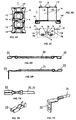
- FIG. 6A is a side view showing an extension lead for series connection for connecting the respective lead wires of two coils in the double coil unit shown in FIGS. 5A to 5C ;
- FIG. 6B is a side view showing an extension lead for external connection to be connected to a lead wire of each coil in the double coil unit shown in FIGS. 5A to 5C ;
- FIG. 7A is a plan view showing a structure of a connector provided at each end of the extension lead for series connection shown in FIG. 6A and at one end of the extension lead for external connection shown in FIG. 6B ;
- FIG. 7B is a perspective view showing the connector shown in FIG. 7A ;
- FIG. 7C is a perspective view showing a structure of a solderless terminal provided at the other end of the extension lead for external connection shown in FIG. 6B ;
- FIG. 8A is a longitudinal sectional view showing the whole structure of an electromagnetic contactor mounting a related double coil unit for an operating electromagnet;
- FIG. 8B is a plan view showing the electromagnet section of the electromagnetic contactor shown in FIG. 8A ;
- FIG. 8C is a longitudinal sectional view showing the electromagnet section shown in FIG. 8B ;
- FIG. 9A is a perspective view showing the assembled structure of a related single coil unit forming the double coil unit shown in FIGS. 8A to 8C ;
- FIG. 9B is a perspective view showing a bobbin of the related single coil unit shown in FIG. 9A ;
- FIG. 9C is a transverse sectional view showing the coil section of the related single coil unit shown in FIG. 9A ;
- FIG. 9D is a side view showing a state in which an initial side lead wire of the coil is temporarily fastened to the bobbin with a piece of adhesive tape in the related single coil unit shown in FIG. 9A ;
- FIG. 9E is a side view showing a state in which a final side lead wire of the coil is temporarily fastened to the coil with a piece of adhesive tape in the related single coil unit shown in FIG. 9A ;
- FIG. 10A is a plan view showing a structure of the related double coil unit assembled with two sets of the related single coil units coupled each of which is shown in FIG. 9A ;
- FIG. 10B is a side view showing the structure of the related double coil unit shown in FIG. 10A ;
- FIG. 10C is a front view showing the structure of the related double coil unit shown in FIG. 10A ;
- FIG. 10D is a connection diagram of the related double coil unit shown in FIGS. 10A to 10C .
- FIG. 1A is a perspective view showing the structure of a bobbin of a single coil unit according to the example of the invention
- FIG. 1B is a perspective view showing the structure of a terminal metal piece to be press fitted to the bobbin shown in FIG. 1A
- FIG. 2A is a plan view showing the external shape of the bobbin shown in FIG. 1A
- FIG. 2B is a side view showing the external shape of the bobbin shown in FIG. 2A
- FIG. 1A is a perspective view showing the structure of
- FIG. 3 is an enlarged perspective view showing a terminal metal piece mounting base in the section indicated by the arrow A in FIG. 1A
- FIG. 4 is an enlarged perspective view showing the terminal metal piece mounting base in FIG. 3 with the terminal metal piece shown in FIG. 1A being attached thereto by press fitting
- FIG. 5A is a plan view showing the structure of a double coil unit formed with two sets of single coil units shown in FIG. 1A arranged side by side to be combined
- FIG. 5B is a side view showing the structure of the double coil unit shown in FIG. 5A
- FIG. 5C is a connection diagram of the double coil unit shown in FIGS. 5A and 5B
- FIG. 6A is a side view showing an extension lead for series connection for connecting the respective lead wires of two coils in the double coil unit shown in FIGS. 5A to 5C
- FIG. 6B is a side view showing an extension lead for external connection to be connected to a lead wire of each coil in the double coil unit shown in FIGS. 5A to 5C
- FIG. 7A is a plan view showing a structure of a connector provided at each end of the extension lead for series connection shown in FIG. 6A and at one end of the extension lead for external connection shown in FIG. 6B
- FIG. 7B is a perspective view showing the connector shown in FIG. 7A
- FIG. 7C is a perspective view showing a structure of a solderless terminal provided at the other end of the extension lead for external connection shown in FIG. 6B .
- the constituents corresponding to those shown in FIG. 9A to FIG. 10D are denoted with the same reference numerals and signs with detailed explanation thereof will be omitted.
- a terminal metal piece 19 shown in FIG. 1B is press fitted into each of a pair of terminal metal piece mounting bases 15 f formed in a lower flange 15 c of a bobbin 15 shown in FIG. 1A .
- a terminal metal piece 19 shown in FIG. 1B is press fitted.
- an initial side lead wire 16 a (see FIG. 4 ) of a coil 16 is wound to be temporarily fastened to the terminal metal piece 19 before a coil strand is wound around the barrel 15 a of the bobbin 15 by an automatic coil winding machine.
- a final side lead wire 16 b see FIG.
- the lower flange 15 c of the bobbin 15 is provided with a pair of the terminal metal piece mounting bases 15 f respectively formed at the right and left corners on the side opposite to a coupling tab 15 d .
- the terminal metal piece mounting base 15 f has an L-shaped press fitting groove 15 f - 1 (see FIG. 3 ) opened on its rear wall.
- the terminal metal piece 19 is formed with a press fitting base 19 a bent in an L-shape corresponding to the shape of the press fitting groove 15 f - 1 , the coil connecting arm 19 b projecting forward from the press fitting base 19 a , the tab terminal 19 c to be inserted into the connector 22 of the extension lead for series connection 20 or of the extension lead for external connection 21 for a plug-in connection with the connector 22 , and further, teeth 19 d for preventing missing at each end rim of the press fitting base 19 a .
- the terminal metal piece 19 is, as shown in FIG. 1A , inserted into the terminal metal piece mounting base 15 f of the bobbin 15 from the side to be kept being secured at a specified position with the press fitting base 19 a press fitted into the press fitting groove 15 f - 1 .
- the initial side lead wire 16 a is first wound several times around the coil connecting arm 19 b of one of the terminal metal pieces 19 to be temporarily fastened to the arm 19 b (see FIG. 4 ).
- the coil strand is wound around the barrel 15 a of the bobbin 15 .
- the final side lead wire 16 b is wound several times around the coil connecting arm 19 b of the other terminal metal piece 19 to be temporarily fastened to the arm 19 b .
- the respective bobbins 15 of the single coil units 11 A and 11 B are made butted against each other while being arranged side by side to be coupled as shown in FIGS. 5A and 5B with the coupling tab 15 d formed in each of an upper flange 15 b and the lower flange 15 c of the one bobbin 15 made engaged with the engaging projection 15 e formed in each of the upper and lower flanges 15 b and 15 c of the other bobbin 15 .
- a strip of insulating tape is kept being wound several times around over the outside of the coils 16 in both of the single coil units 11 A and 11 B.
- the connector 22 (see FIGS. 7A and 7B ) attached to each end of the extension lead for series connection 20 (see FIG. 6A ) is then made to have the tab terminal 19 c inserted which is formed in the terminal metal piece 19 connected to the final side lead wire 16 b of the coil strand of the coil 16 in each of the single coil units 11 A and 11 B.
- the connector 22 attached to one end of the extension lead for external connection 21 is made to have the tab terminal 19 c inserted which is formed in the terminal metal piece 19 connected to the initial side lead wire 16 a of the coil strand of the coil 16 in each of the single coil units 11 A and 11 B.
- a solderless terminal 23 (see FIG. 7C ) is attached which is to be connected to a control terminal of an electromagnetic contactor.
- the double coil unit 11 is, like the related one, mounted on a stationary core of an operating electromagnet (double leg core) to be assembled in an electromagnetic contactor.
- the double coil unit 11 in the example shown in the attached drawings requires no troublesome manual work as that carried out in forming the related structure explained with reference to FIG. 9A to FIG. 10D in which each of the initial side lead wire 16 a and the final side lead wire 16 b of the coil 16 is temporarily fastened with a piece of the adhesive tape 18 for each of the single coil units 11 A and 11 B.
- the coil winding work can be carried out by using an automatic wire winding machine with manual work of only winding each of the initial side lead wire 16 a and the final side lead wire 16 b of the coil 16 around the corresponding coil connecting arm 19 b formed in the terminal metal piece 19 .
- the extension leads can be connected by a single operation with plug-in ease of only making the connector 22 of each of the extension lead for series connection 20 and the extension leads for external connection 21 have the corresponding tab terminal 19 c in the terminal metal piece 19 inserted therein. This can reduce working man-hours of manual work to considerably lower the cost compared with that of the related structure.
Landscapes
- Engineering & Computer Science (AREA)
- Power Engineering (AREA)
- Physics & Mathematics (AREA)
- Electromagnetism (AREA)
- Manufacturing & Machinery (AREA)
- Electromagnets (AREA)
Applications Claiming Priority (2)
| Application Number | Priority Date | Filing Date | Title |
|---|---|---|---|
| JP2008-240406 | 2008-09-19 | ||
| JP2008240406A JP4706742B2 (ja) | 2008-09-19 | 2008-09-19 | 電磁接触器のコイルユニットおよびその組立方法 |
Publications (2)
| Publication Number | Publication Date |
|---|---|
| US20100073117A1 US20100073117A1 (en) | 2010-03-25 |
| US8040211B2 true US8040211B2 (en) | 2011-10-18 |
Family
ID=41693977
Family Applications (1)
| Application Number | Title | Priority Date | Filing Date |
|---|---|---|---|
| US12/558,674 Expired - Fee Related US8040211B2 (en) | 2008-09-19 | 2009-09-14 | Coil unit of electromagnetic contactor and assembling method thereof |
Country Status (5)
| Country | Link |
|---|---|
| US (1) | US8040211B2 (zh) |
| JP (1) | JP4706742B2 (zh) |
| CN (1) | CN101677043B (zh) |
| DE (1) | DE102009035510B4 (zh) |
| FR (1) | FR2936350B1 (zh) |
Cited By (1)
| Publication number | Priority date | Publication date | Assignee | Title |
|---|---|---|---|---|
| WO2021224826A1 (en) * | 2020-05-06 | 2021-11-11 | Padmini Vna Mechatronics Pvt. Ltd. | Coil assembly with terminal joint connection and process thereof |
Families Citing this family (13)
| Publication number | Priority date | Publication date | Assignee | Title |
|---|---|---|---|---|
| JP5777440B2 (ja) * | 2011-08-03 | 2015-09-09 | 富士通コンポーネント株式会社 | 電磁継電器及び電磁継電器の製造方法 |
| CN102867695B (zh) * | 2012-09-24 | 2015-12-16 | 浙江环方汽车电器有限公司 | 一种电磁开关的线圈座 |
| JP6060631B2 (ja) * | 2012-11-08 | 2017-01-18 | 富士電機機器制御株式会社 | 電磁接触器 |
| CN104733228A (zh) * | 2013-12-20 | 2015-06-24 | 珠海格力电器股份有限公司 | 量化控制交流接触器走线余量的方法及交流接触器 |
| CN104979141B (zh) * | 2014-04-08 | 2017-09-26 | 三菱电机株式会社 | 断路器 |
| CN105097361B (zh) * | 2014-05-09 | 2019-01-22 | 伊顿公司 | 线圈组件、电路板及接触器 |
| CN104078250B (zh) * | 2014-06-27 | 2017-11-28 | 厦门宏发开关设备有限公司 | 一种线圈端子导电片结构 |
| CN104157515B (zh) * | 2014-07-18 | 2017-01-18 | 漳州宏发电声有限公司 | 一种线圈焊片、双线圈继电器及其装配方法 |
| JP6486667B2 (ja) * | 2014-11-28 | 2019-03-20 | 株式会社ユーシン | コイル装置の結線構造 |
| JP6657692B2 (ja) * | 2015-09-11 | 2020-03-04 | オムロン株式会社 | 電磁石装置およびこれを用いた電磁継電器 |
| CN109702450B (zh) * | 2019-02-27 | 2024-03-15 | 东莞市春之田自动化科技有限公司 | 一种推送检测机构及防盗线圈的全自动组装机 |
| DE102020203056A1 (de) * | 2020-03-10 | 2021-09-16 | Te Connectivity Germany Gmbh | Elektrische Schaltvorrichtung, insbesondere ein Stromschütz oder ein Relais, mit Kontaktierungselement und Befestigungselement |
| CN113394055B (zh) * | 2021-06-23 | 2022-07-05 | 宁波力顺继电器有限公司 | 一种便于组装的继电器 |
Citations (7)
| Publication number | Priority date | Publication date | Assignee | Title |
|---|---|---|---|---|
| US4423399A (en) * | 1982-04-23 | 1983-12-27 | Essex Group, Inc. | Electromagnetic contactor |
| US4724410A (en) * | 1986-09-25 | 1988-02-09 | Furnas Electric Company | Electrical contactor |
| US4889505A (en) * | 1985-04-09 | 1989-12-26 | Square D Company | Terminal assembly for a coil |
| US4969844A (en) * | 1988-10-06 | 1990-11-13 | Mitsubishi Denki Kabushiki Kaisha | Electromagnetic contector |
| JPH06260069A (ja) | 1993-03-01 | 1994-09-16 | Mitsubishi Denki Eng Kk | 電磁コイル、この電磁コイルを用いる電磁接触器及びこの電磁コイルの製造方法 |
| JP2000057924A (ja) | 1998-08-10 | 2000-02-25 | Fuji Electric Co Ltd | 電磁石装置のコイル端子部 |
| JP2003257727A (ja) | 2002-03-04 | 2003-09-12 | Sumitomo Wiring Syst Ltd | コイル装置 |
Family Cites Families (7)
| Publication number | Priority date | Publication date | Assignee | Title |
|---|---|---|---|---|
| JPS454450Y1 (zh) * | 1967-05-16 | 1970-02-28 | ||
| JPS5123876Y1 (zh) * | 1974-01-08 | 1976-06-18 | ||
| JPS50152140U (zh) * | 1974-06-03 | 1975-12-17 | ||
| JPS5814580Y2 (ja) * | 1978-06-13 | 1983-03-23 | 株式会社東芝 | 電磁コイル |
| JPS625618A (ja) * | 1985-07-02 | 1987-01-12 | Matsushita Electric Ind Co Ltd | チツプ・インダクタ |
| JPH05128953A (ja) * | 1991-11-05 | 1993-05-25 | Mitsubishi Electric Corp | 電磁接触器 |
| JPH1064398A (ja) * | 1996-08-20 | 1998-03-06 | Fuji Electric Co Ltd | 電磁接触器 |
-
2008
- 2008-09-19 JP JP2008240406A patent/JP4706742B2/ja active Active
-
2009
- 2009-07-31 DE DE102009035510.3A patent/DE102009035510B4/de not_active Expired - Fee Related
- 2009-08-03 CN CN200910165412.XA patent/CN101677043B/zh active Active
- 2009-08-21 FR FR0904020A patent/FR2936350B1/fr not_active Expired - Fee Related
- 2009-09-14 US US12/558,674 patent/US8040211B2/en not_active Expired - Fee Related
Patent Citations (8)
| Publication number | Priority date | Publication date | Assignee | Title |
|---|---|---|---|---|
| US4423399A (en) * | 1982-04-23 | 1983-12-27 | Essex Group, Inc. | Electromagnetic contactor |
| US4889505A (en) * | 1985-04-09 | 1989-12-26 | Square D Company | Terminal assembly for a coil |
| US4724410A (en) * | 1986-09-25 | 1988-02-09 | Furnas Electric Company | Electrical contactor |
| US4969844A (en) * | 1988-10-06 | 1990-11-13 | Mitsubishi Denki Kabushiki Kaisha | Electromagnetic contector |
| JPH06260069A (ja) | 1993-03-01 | 1994-09-16 | Mitsubishi Denki Eng Kk | 電磁コイル、この電磁コイルを用いる電磁接触器及びこの電磁コイルの製造方法 |
| US5517167A (en) | 1993-03-01 | 1996-05-14 | Mitsubishi Denki Kabushiki Kaisha | Magnetic coil, magnetic contactor using magnetic coil, and magnetic coil manufacturing method |
| JP2000057924A (ja) | 1998-08-10 | 2000-02-25 | Fuji Electric Co Ltd | 電磁石装置のコイル端子部 |
| JP2003257727A (ja) | 2002-03-04 | 2003-09-12 | Sumitomo Wiring Syst Ltd | コイル装置 |
Non-Patent Citations (4)
| Title |
|---|
| "A Structure of an Electromagnetic Contractor and Designations of Parts Thereof, SC-N6", (online) Fuji Electric Technica Co., Ltd., [Retrieved on Aug. 30, 2008], Internet URL:http://www.fe-technica.co.jp/html/shohin/41/pdf/AH294-P1-10-17.pdf, pp. 1-10 through 1-17. (English Translation). |
| "A Structure of an Electromagnetic Contractor and Designations of Parts Thereof, SC-N6", (online) Fuji Electric Technica Co., Ltd., [Retrieved on Aug. 30, 2008], Internet URL:http://www.fe-technica.co.jp/html/shohin/41/pdf/AH294—P1—10-17.pdf, pp. 1-10 through 1-17. (English Translation). |
| Notification of Reasons for Refusal issued in corresponding Japanese Patent Application No. 2008-240406 dated Dec. 21, 2010. Partial English Translation provided. |
| Preliminary Search Report issued in corresponding French Patent Application No. 0904020 dated Nov. 19, 2010. Partial English Translation provided. |
Cited By (1)
| Publication number | Priority date | Publication date | Assignee | Title |
|---|---|---|---|---|
| WO2021224826A1 (en) * | 2020-05-06 | 2021-11-11 | Padmini Vna Mechatronics Pvt. Ltd. | Coil assembly with terminal joint connection and process thereof |
Also Published As
| Publication number | Publication date |
|---|---|
| JP4706742B2 (ja) | 2011-06-22 |
| DE102009035510B4 (de) | 2022-05-19 |
| CN101677043B (zh) | 2014-02-26 |
| DE102009035510A1 (de) | 2010-03-25 |
| US20100073117A1 (en) | 2010-03-25 |
| CN101677043A (zh) | 2010-03-24 |
| FR2936350B1 (fr) | 2013-02-22 |
| FR2936350A1 (fr) | 2010-03-26 |
| JP2010073519A (ja) | 2010-04-02 |
Similar Documents
| Publication | Publication Date | Title |
|---|---|---|
| US8040211B2 (en) | Coil unit of electromagnetic contactor and assembling method thereof | |
| JP2008112753A (ja) | 横型低背コイル部品及びその巻線端末のはんだ付け方法 | |
| JPH02160389A (ja) | モジュラージャック | |
| US7839252B2 (en) | Spool, brake and electric motor | |
| JP2014110673A (ja) | 固定子の動力線接続構造 | |
| JPH0729751A (ja) | 内燃機関用点火コイル | |
| JP2002272050A (ja) | レゾルバステータ構造 | |
| WO2007086412A1 (ja) | 巻線部品 | |
| US4975739A (en) | Electromagnetic relay | |
| CN101740199A (zh) | 磁性电子元件的制造方法 | |
| JP3699442B2 (ja) | ソレノイド | |
| JP3809687B2 (ja) | 電磁継電器及びその製造方法 | |
| JP2000260284A (ja) | 電磁リレー及びその組立て方法 | |
| JPS625622A (ja) | トランス | |
| CN219534417U (zh) | 一种继电器的线圈引出件和电磁继电器 | |
| CN217061920U (zh) | 一种时间继电器 | |
| CN111953113B (zh) | 一种电机及其定子 | |
| CN216871857U (zh) | 一种电磁继电器和时间继电器 | |
| JPH07283044A (ja) | トランス | |
| JPH04277429A (ja) | 電磁継電器 | |
| KR100494988B1 (ko) | 스프라이스 커넥터 | |
| JPH11186064A (ja) | 小形コイル装置及びその製造方法 | |
| JP2003194857A (ja) | 電流検出器 | |
| CN114530351A (zh) | 一种电磁继电器及其与pcba板的连接方法和时间继电器 | |
| JP2019212876A (ja) | コイル部品 |
Legal Events
| Date | Code | Title | Description |
|---|---|---|---|
| AS | Assignment |
Owner name: FUJI ELECTRIC FA COMPONENTS & SYSTEMS CO., LTD.,JA Free format text: ASSIGNMENT OF ASSIGNORS INTEREST;ASSIGNOR:DAJIMA, HIDEKI;REEL/FRAME:023481/0546 Effective date: 20091002 Owner name: FUJI ELECTRIC FA COMPONENTS & SYSTEMS CO., LTD., J Free format text: ASSIGNMENT OF ASSIGNORS INTEREST;ASSIGNOR:DAJIMA, HIDEKI;REEL/FRAME:023481/0546 Effective date: 20091002 |
|
| ZAAA | Notice of allowance and fees due |
Free format text: ORIGINAL CODE: NOA |
|
| ZAAB | Notice of allowance mailed |
Free format text: ORIGINAL CODE: MN/=. |
|
| STCF | Information on status: patent grant |
Free format text: PATENTED CASE |
|
| FEPP | Fee payment procedure |
Free format text: PAYOR NUMBER ASSIGNED (ORIGINAL EVENT CODE: ASPN); ENTITY STATUS OF PATENT OWNER: LARGE ENTITY |
|
| FPAY | Fee payment |
Year of fee payment: 4 |
|
| MAFP | Maintenance fee payment |
Free format text: PAYMENT OF MAINTENANCE FEE, 8TH YEAR, LARGE ENTITY (ORIGINAL EVENT CODE: M1552); ENTITY STATUS OF PATENT OWNER: LARGE ENTITY Year of fee payment: 8 |
|
| AS | Assignment |
Owner name: FUJI ELECTRIC FA COMPONENTS & SYSTEMS CO., LTD., JAPAN Free format text: CHANGE OF ADDRESS;ASSIGNOR:FUJI ELECTRIC FA COMPONENTS & SYSTEMS CO., LTD.;REEL/FRAME:059207/0192 Effective date: 20210826 |
|
| FEPP | Fee payment procedure |
Free format text: MAINTENANCE FEE REMINDER MAILED (ORIGINAL EVENT CODE: REM.); ENTITY STATUS OF PATENT OWNER: LARGE ENTITY |
|
| LAPS | Lapse for failure to pay maintenance fees |
Free format text: PATENT EXPIRED FOR FAILURE TO PAY MAINTENANCE FEES (ORIGINAL EVENT CODE: EXP.); ENTITY STATUS OF PATENT OWNER: LARGE ENTITY |
|
| STCH | Information on status: patent discontinuation |
Free format text: PATENT EXPIRED DUE TO NONPAYMENT OF MAINTENANCE FEES UNDER 37 CFR 1.362 |
|
| FP | Lapsed due to failure to pay maintenance fee |
Effective date: 20231018 |