US7948854B2 - Optical head apparatus and optical information recording/reproducing apparatus - Google Patents
Optical head apparatus and optical information recording/reproducing apparatus Download PDFInfo
- Publication number
- US7948854B2 US7948854B2 US12/091,799 US9179906A US7948854B2 US 7948854 B2 US7948854 B2 US 7948854B2 US 9179906 A US9179906 A US 9179906A US 7948854 B2 US7948854 B2 US 7948854B2
- Authority
- US
- United States
- Prior art keywords
- birefringence
- optical
- regions
- plane
- compensating element
- Prior art date
- Legal status (The legal status is an assumption and is not a legal conclusion. Google has not performed a legal analysis and makes no representation as to the accuracy of the status listed.)
- Expired - Fee Related, expires
Links
Images


Classifications
-
- G—PHYSICS
- G11—INFORMATION STORAGE
- G11B—INFORMATION STORAGE BASED ON RELATIVE MOVEMENT BETWEEN RECORD CARRIER AND TRANSDUCER
- G11B7/00—Recording or reproducing by optical means, e.g. recording using a thermal beam of optical radiation by modifying optical properties or the physical structure, reproducing using an optical beam at lower power by sensing optical properties; Record carriers therefor
- G11B7/12—Heads, e.g. forming of the optical beam spot or modulation of the optical beam
- G11B7/135—Means for guiding the beam from the source to the record carrier or from the record carrier to the detector
- G11B7/1392—Means for controlling the beam wavefront, e.g. for correction of aberration
- G11B7/13925—Means for controlling the beam wavefront, e.g. for correction of aberration active, e.g. controlled by electrical or mechanical means
-
- G—PHYSICS
- G11—INFORMATION STORAGE
- G11B—INFORMATION STORAGE BASED ON RELATIVE MOVEMENT BETWEEN RECORD CARRIER AND TRANSDUCER
- G11B7/00—Recording or reproducing by optical means, e.g. recording using a thermal beam of optical radiation by modifying optical properties or the physical structure, reproducing using an optical beam at lower power by sensing optical properties; Record carriers therefor
- G11B7/12—Heads, e.g. forming of the optical beam spot or modulation of the optical beam
- G11B7/135—Means for guiding the beam from the source to the record carrier or from the record carrier to the detector
- G11B7/1353—Diffractive elements, e.g. holograms or gratings
-
- G—PHYSICS
- G11—INFORMATION STORAGE
- G11B—INFORMATION STORAGE BASED ON RELATIVE MOVEMENT BETWEEN RECORD CARRIER AND TRANSDUCER
- G11B7/00—Recording or reproducing by optical means, e.g. recording using a thermal beam of optical radiation by modifying optical properties or the physical structure, reproducing using an optical beam at lower power by sensing optical properties; Record carriers therefor
- G11B7/12—Heads, e.g. forming of the optical beam spot or modulation of the optical beam
- G11B7/135—Means for guiding the beam from the source to the record carrier or from the record carrier to the detector
- G11B7/1365—Separate or integrated refractive elements, e.g. wave plates
- G11B7/1369—Active plates, e.g. liquid crystal panels or electrostrictive elements
-
- G—PHYSICS
- G11—INFORMATION STORAGE
- G11B—INFORMATION STORAGE BASED ON RELATIVE MOVEMENT BETWEEN RECORD CARRIER AND TRANSDUCER
- G11B7/00—Recording or reproducing by optical means, e.g. recording using a thermal beam of optical radiation by modifying optical properties or the physical structure, reproducing using an optical beam at lower power by sensing optical properties; Record carriers therefor
- G11B7/12—Heads, e.g. forming of the optical beam spot or modulation of the optical beam
- G11B7/135—Means for guiding the beam from the source to the record carrier or from the record carrier to the detector
- G11B7/1392—Means for controlling the beam wavefront, e.g. for correction of aberration
- G11B7/13922—Means for controlling the beam wavefront, e.g. for correction of aberration passive
-
- G—PHYSICS
- G11—INFORMATION STORAGE
- G11B—INFORMATION STORAGE BASED ON RELATIVE MOVEMENT BETWEEN RECORD CARRIER AND TRANSDUCER
- G11B7/00—Recording or reproducing by optical means, e.g. recording using a thermal beam of optical radiation by modifying optical properties or the physical structure, reproducing using an optical beam at lower power by sensing optical properties; Record carriers therefor
- G11B7/08—Disposition or mounting of heads or light sources relatively to record carriers
- G11B7/09—Disposition or mounting of heads or light sources relatively to record carriers with provision for moving the light beam or focus plane for the purpose of maintaining alignment of the light beam relative to the record carrier during transducing operation, e.g. to compensate for surface irregularities of the latter or for track following
- G11B7/0901—Disposition or mounting of heads or light sources relatively to record carriers with provision for moving the light beam or focus plane for the purpose of maintaining alignment of the light beam relative to the record carrier during transducing operation, e.g. to compensate for surface irregularities of the latter or for track following for track following only
- G11B7/0906—Differential phase difference systems
Definitions
- the present invention relates to an optical information recording/reproducing apparatus for recording/reproducing information onto or from an optical recording medium, and an optical head apparatus incorporated within the optical information recording/reproducing apparatus.
- FIG. 26 shows the configuration of a conventional typical optical head apparatus.
- the optical head apparatus is provided with a semiconductor laser 1 , a collimator lens 2 , a polarizing beam splitter 3 , a quarter-wave plate 4 , an objective lens 6 , a cylindrical lens 8 , a convex lens 9 and a photo-detector 10 .
- the output light emitted by the semiconductor laser 1 which serves as a light source, is collimated by the collimator lens 2 .
- the collimated light enters into the polarizing beam splitter 3 as a P-polarized light, and almost 100% thereof enters the quarter-wave plate 4 after passing through the polarizing beam splitter 3 .
- the quarter-wave plate 4 converts the incoming light from linear to circular polarized light when the incoming light passes therethrough.
- the circular polarized light is focused by the objective lens 6 onto a disc 7 , which is a sort of optical recording medium.
- the reflected light reflected by the disc 7 passes through the objective lens 6 in the opposite direction and enters the quarter-wave plate 4 .
- the quarter-wave plate 4 converts the incoming light from circular to linear polarized light when the incoming light passes therethrough.
- the direction of polarization of the linear-polarized light on this return path is orthogonal to that of the linear-polarized light on the outward path.
- the linear-polarized light enters the polarizing beam splitter 3 as an S-polarized light, and almost 100% thereof enters the cylindrical lens 8 , after being reflected. This light passes through the cylindrical lens 8 and the convex lens 9 and is received by the photo-detector 10 .
- Such an optical system which incorporates a polarizing beam splitter and a quarter-wave plate, is referred to as a polarization optical system.
- the optical head apparatus using a polarization optical system is featured in that there is nearly no light loss in the polarizing beam splitter which separates the light of the outward path and the light of the return path for both of the return and outward paths. Therefore, the optical head apparatus using a polarization optical system offers a high optical output in recording operations, while offering a high S/N ratio in reproducing operations; the optical head apparatus using a polarization optical system is mainly used as an optical head apparatus adapted to write-once read-many optical recording mediums and rewritable optical recording mediums.
- the optical head apparatus using a polarization optical system is also as an optical head apparatus adapted to read-only optical recording mediums.
- Write-once-read-many optical recording mediums and rewritable optical recording mediums are usually provided with grooves for achieving tracking.
- the detection is usually achieved by a push-pull method.
- the push-pull method involves receiving a reflected light from an optical recording medium by a photo-detector with the reflected light divided into two regions defined by a straight line which crosses the beam axis on a face vertical to the beam axis and extends in the direction corresponding to the tangential direction of the optical recording medium.
- the track error signal obtained by the push-pull method is given by (Ia ⁇ Ib)/(Ia+Ib).
- One index that represents the quality of the track error signal obtained by the push-pull method is the push-pull signal modulation factor.
- the push-pull signal modulation factor is obtained by dividing the amplitude of the push-pull signal by the level of the sum signal for the case when the focused spot on the optical recording medium crosses the groove of the optical recording medium. In other words, the push-pull signal modulation factor corresponds to the amplitude of the track error signal obtained by the push-pull method.
- read-only optical recording mediums are usually provided with pits for achieving tracking.
- the detection is usually achieved by a DPD (Differential Phase Detection) technique.
- the DPD method involves receiving a reflected light from an optical recording medium by a photo-detector with the reflected light divided into four regions defined by straight lines which each cross the beam axis on a face vertical to the beam axis, one extending in the direction corresponding to the radial direction of the optical recording medium and the other extending in the direction corresponding to the tangential direction.
- the track error signal (DPD signal) obtained by the DPD method is given by the temporal difference between (Ia+Ic) and (Ib+Id).
- One index which represents the quality of the track error signal obtained by the DPD method is the DPD signal amplitude.
- the DPD signal is defined as the amplitude of the DPS signal standardized by the duration of the channel clock for the case when the focused spot on the optical recording medium crosses a pit of the optical recording medium. That is, the DPD signal amplitude corresponds to the amplitude of the track error signal obtained by the DPD method.
- the push-pull signal modulation factor and the DPD signal amplitude varies depending on the in-plane position of the optical recording medium.
- a gain of the track servo which is optimally adjusted for the position where the push-pull signal modulation factor and the DPD signal amplitude are high is excessively low for the position where the push-pull signal modulation factor and the DPD signal amplitude are low, causing the residual error in the track servo.
- a gain of the track servo which is optimally adjusted for the position where the push-pull signal modulation factor and the DPD signal amplitude are low is excessively high for the position where the push-pull signal modulation factor and the DPD signal amplitude are high, resulting in the oscillation of the track servo. Therefore, it is necessary to decrease the changes in the push-pull signal modulation factor and DPD signal amplitude depending on the in-plane position of the optical recording medium, in order to achieve the stable track servo control for all the in-plane positions of the optical recording medium.
- the allowed maximum change in the push-pull signal modulation factor depending on the in-plane position of the optical recording medium is defined by the written standards of the optical recording medium.
- the standard for the DVD-R system requires: ( PP max ⁇ PP min )/( PP max +PP min ) ⁇ 0.15, where PP max and PP min are the maximum and minimum values of the push-pull signal modulation factor, respectively.
- an optical head apparatus and an optical information recording/reproducing apparatus which record or reproduce information onto or from such optical recording mediums require measures for suppressing the changes in the push-pull signal modulation factor and DPD signal amplitude depending on the in-plane position of the optical recording medium.
- polycarbonate which exhibits birefringence
- polycarbonate which exhibits birefringence
- polycarbonate which exhibits birefringence
- the use of an optical head apparatus based on a polarization optical system for recording or reproducing information onto or from an optical recording medium with a protective layer exhibiting birefringence causes reduction in the amount of light received.
- the disc 7 which is an optical recording medium
- XYZ-coordinates as shown in FIG. 27 .
- the X-axis is defined as the radius direction of the disc 7
- the Y-axis as the tangential direction
- the Z-axis as the normal direction of the disc 7 .
- the protective layer usually exhibits biaxial anisotropy in the refractive index, and the three main axes substantially coincide with the X-axis, the Y-axis and the Z-axis.
- the value ⁇ n i of the in-plane birefringence depends on the manufacturing conditions of the protective layer and varies in accordance with the in-plane position of the optical recording medium.
- the value ⁇ n v of the vertical birefringence is substantially uniquely determined in accordance with the material of the protective layer, kept approximately constant, independently of the in-plain position of the optical recording medium.
- polycarbonate is used as the protective layer
- the value ⁇ n i of the in-plane birefringence varies over a range of about ⁇ 3 ⁇ 10 ⁇ 5
- the value ⁇ n v of vertical birefringence is approximately constant within a range between about 6 ⁇ 10 ⁇ 4 and about 8 ⁇ 10 ⁇ 4 .
- a technique for separately measuring the in-plane and vertical birefringence of the protective layer as thus described is disclosed in, for example, Japanese Laid Open Patent Application No. JP 2004-163225 A.
- the inventor of the present invention have found out that the above-described changes in the push-pull signal modulation factor and DPD signal amplitude depending on the in-plane position of the optical recording medium is caused by the changes in the in-plane birefringence depending on the in-plane position of the optical recording medium under the existence of the vertical birefringence.
- the influence of the birefringence is increased as the wavelength of the light source is reduced.
- the HD DVD-R system and the HD DVD-ROM system which use a light source with a wavelength of about 405 nm for recording/reproducing, experience larger changes in the push-pull signal modulation factor and the DPD signal amplitude than the DVD-R system and the DVD-ROM system, which uses a light source with a wavelength of about 660 nm for recording/reproducing.
- FIG. 28 shows a calculation example of the relation between the value of in-plane birefringence and the sum signal level with the value of vertical birefringence used as a parameter
- FIG. 29 shows a calculation example of the relation between the value of in-plane birefringence and the push-pull signal amplitude with the value of vertical birefringence used as a parameter
- FIG. 30 shows a calculation example of the relation between the value of in-plane birefringence and the push-pull signal modulation factor with the value of vertical birefringence used as the parameter, which is obtained from the sum signal level shown in FIG. 28 and the push-pull signal amplitude shown in FIG. 29 .
- the calculation conditions are as follows: the wavelength of the light source is 405 nm, the opening number of the objective lens is 0.65, the thickness of the protective layer of the optical recording medium is 0.6 mm, the pitch of the groove is 0.4 ⁇ m, and the depth of the groove is 25 nm. These conditions correspond to the conditions for the HD DVD-R system.
- the vertical axes of FIG. 28 and FIG. 29 are standardized at the sum signal level for the case when the groove is not formed on the optical recording medium. Black circles on the drawings indicate the calculation result for the value of vertical birefringence being 0, and white circles on the drawings indicate the calculation result for the value of vertical birefringence being 7 ⁇ 10 ⁇ 4 .
- the sum signal level shows the maximum value when the value ⁇ n i of in-plane birefringence is 0, for both of the cases with or without the existence of vertical birefringence, and the sum signal level decreases as the absolute value of the value ⁇ n i of in-plane birefringence is increased.
- the push-pull signal amplitude shows the maximum value when the value ⁇ n i of in-plane birefringence is 0, similarly to the sum signal level and the push-pull signal amplitude is decreased as the absolute value of the value ⁇ n i of in-plane birefringence is increased, for the case when the vertical birefringence does not exist; however, for the case when the vertical birefringence exists, the push-pull signal amplitude is monotonously decreased as the value ⁇ n i of in-plane birefringence is changed from positive to negative values. As a result, as shown in FIG.
- the push-pull signal modulation factor is constant independently of the value ⁇ n i of in-plane birefringence, when the vertical birefringence does not exist, while the push-pull signal modulation factor is monotonously decreased as the value ⁇ n i of in-plane birefringence is changed from positive to negative values under the existence of the vertical birefringence.
- (PP max ⁇ PP min )/(PP max +PP min ) is required to be less than 0.15, which is the allowed maximum value defined by the standard for the DVD-R system, and the variation in the value ⁇ n i of in-plane birefringence is required to be reduced within a range of ⁇ 1.15 ⁇ 10 ⁇ 5 (the difference between the maximum and minimum values is 2.3 ⁇ 10 ⁇ 5 ).
- (PP max ⁇ PP min )/(PP max +PP min ) is required to be less than 0.15 for the value ⁇ n v of vertical birefringence ranging between 6 ⁇ 10 ⁇ 4 and 8 ⁇ 10 ⁇ 4
- the product of ⁇ n v and ( ⁇ n imax ⁇ n imin ) is required to be equal to or less than 1.6 ⁇ 10 ⁇ 8
- the maximum and minimum values of in-plane birefringence are defined as ⁇ n imax , ⁇ n imin , respectively.
- (PP max ⁇ PP min )/(PP max +PP min ) is reduced below 0.15 by the reduction of the effective value ⁇ n v of vertical birefringence down to 2.7 ⁇ 10 ⁇ 4 or less, which is a measure for suppressing the change in the push-pull signal modulation factor depending on the in plane position of the optical recording medium, even when the value ⁇ n i of in-plane birefringence varies over a range of +3 ⁇ 10 ⁇ 5 (the difference between the maximum and minimum values is 6 ⁇ 10 ⁇ 5 ).
- FIG. 31 shows a calculation example of the relation between the value of in-plane birefringence and the DPD signal amplitude with the value of vertical birefringence used as a parameter.
- the calculation conditions are as follows: the wavelength of the light source is 405 nm, the opening number of the objective lens is 0.65, the thickness of the protective layer of the optical recording medium is 0.6 mm, the pitch of the pits is 0.4 ⁇ m, and the depth of the pits is 25 nm. These conditions correspond to the conditions for the HD DVD-ROM system.
- the vertical axis of FIG. 31 is standardized by the duration of the channel clock.
- the black circles on the drawing indicate the calculation result for the value of vertical birefringence being 0, and the white circles on the drawing indicate the calculation result for the value of vertical birefringence being 7 ⁇ 10 ⁇ 4 .
- the DPD signal amplitude is constant independently of the value ⁇ n i of in-plane birefringence when no vertical birefringence exists; however, under the existence of vertical birefringence, the DPD signal amplitude is monotonously decreased as the value ⁇ n i of in-plane birefringence is changed from positive to negative values.
- the birefringence of the protective layer of the disc 7 causes the reflected light from the disc 7 to be converted into an elliptically-polarized light after passing through the quarter-wave plate 4 . That is, the S-polarized component for the polarizing beam splitter 3 is decreased, while the P-polarized component is generated. Accordingly, nearly 100% of the S-polarized component is reflected by the polarizing beam splitter 3 and received by the photo-detector 10 , while nearly 100% of the P-polarized component passes through the polarizing beam splitter 3 and returns to the semiconductor laser 1 . This is the reason of the decrease in the amount of light received by the photo-detector 10 .
- the birefringence of the protective layer offers an optical phase difference between the polarization components in the X-axis and Y-axis directions for the light passing through the protective layer.
- the optical phase difference is defined as positive when the phase of the polarization component in the X-axis direction leads ahead of the phase of the polarization component in the Y-axis direction, while the optical phase difference is defined as negative when the phase of the polarization component in the X-axis direction lags behind the phase of the polarization component in the Y-axis direction.
- the influence of the in-plane birefringence on the light passing through the protective layer of the optical recording medium does not depend on the input direction to the optical recording medium and the incident angle thereof.
- Positive in-plane birefringence causes a constant negative optical phase difference over a section vertical to the beam axis of the light passing through the protective layer
- negative in-plane birefringence causes a constant positive optical phase difference over the section vertical to the beam axis of the light passing through the protective layer.
- the influence of the vertical birefringence on the light passing through the protective layer of the optical recording medium depends on the incident direction and angle to the optical recording medium.
- the original point is defined as the intersection of the beam axis on a section vertical to the beam axis of the light passing through the protective layer
- the optical phase difference generated at the original point is 0, and the absolute value of the generated optical phase difference is increased with the distance the original point.
- Substrates which correspond to the protective layers for substrate-incident optical recording mediums, such as HD-DVDs, are usually manufactured through injection molding.
- the in-plane birefringence depends on the position in the radius direction of the optical recording medium, while exhibiting substantially no dependency on the position in the tangential direction. Specifically, the in-plane birefringence is positive in the inner portion of the optical recording medium, and the in-plane birefringence monotonously decreases from the inside to the outside; the in-plane birefringence is negative in the outer portion.
- the push-pull signal modulation factor and the DPD signal amplitude are high in the inner portion of the optical recording medium, monotonously decreasing as it goes from inner to outer portion; the push-pull signal modulation factor and the DPD signal amplitude are low in the outer portion.
- covers which correspond to the protective layers for cover-incident optical recording mediums such as BDs, are usually manufactured by punching of sheets.
- the in-plane birefringence depends on the position in the tangential direction of the optical recording medium, while exhibiting substantially no dependency on the position in the radius direction.
- the in-plane birefringence alternately shows a positive local maximum value and a negative local minimum value twice at intervals of 90 degrees for one circulation of the optical recording medium. Therefore, the push-pull signal modulation factor and the DPD signal amplitude alternately show a high maximal value and a low minimal value twice at intervals of 90 degrees for one circulation of the optical recording medium.
- a measuring method of birefringence properties of the optical recording medium is disclosed in Japanese Laid Open Patent Application No. JP-A 2004-163225.
- this conventional measuring method of birefringence properties light is emitted onto a measurement target medium through an objective lens having a numerical aperture equal to or greater than a predetermined numerical aperture, and the light amount of the polarization component in a specific direction within the reflected light reflected on the reflection surface of the measurement target medium is measured and defined as a first amount of light APH.
- the vertical birefringence property of the measurement target medium is determined on the basis of the ratio APH/ANH of the first and second light amounts and the in-plane birefringence property of the measurement target medium.
- An optical disc apparatus is also disclosed in Japanese Laid Open Patent Application No. JP-A2003-248118. Formed on a wavelength plate in this conventional optical disc apparatus are micro cyclic structures sized half or less of the wavelength of the light within a targeted wavelength range. Two substrates are prepared which are opposed with each other with the micro cyclic structures shifted by half a cycle and engaged with each other. The interval between these substrates is adjusted to vary the overlap amount of the micro cyclic structure.
- the thus-configured wavelength plate which has a combined birefringence structure incorporating birefringence structures each having superior controllability of the birefringence property through changing the shape to provide a variable phase difference, covers a wide usage range, adaptably changing the polarization state for the light of wavelengths over the entire desired wavelength range.
- an optical pickup apparatus is disclosed in Japanese Laid Open Patent Application No. JP-A 2004-39018.
- This conventional optical pickup apparatus emits light onto the recording surface of an information recording medium and receives the reflected light from the recording surface.
- the optical pickup apparatus is provided with: an optical system including at least one light source, an objective lens for focusing the light beam emitted from the light source onto the recording surface, and an optical element arranged in the optical path of the light beam emitted from the light source and to the objective lens, which element includes an electro-optic crystal having a refractive index distribution in accordance with the voltage applied through an electrode and exhibiting a longitudinal electro-optic effect for compensating the astigmatism component in the wave aberration of the light beam focused on the recording surface, which system guides the return light beam reflected on the recording surface to a predetermined light receiving position; and a photo-detector arranged on the light reception position.
- An object of the present invention is to provide an optical head apparatus and an optical information recording/reproducing apparatus, which solve the above-mentioned problems of the conventional optical head apparatus using a polarization optical system and suppress the change in the track error signal amplitude depending on the in-plane position of the optical recording medium.
- an optical head apparatus is provided with a light source, an objective lens, a photo-detector, a polarizing splitter unit, a quarter-wave plate, and a birefringence compensating unit to reduce the change in the track error signal amplitude caused by the birefringence in the protective layer of an optical recording medium.
- the objective lens focuses an output light emitted by the light source on the disc-shaped optical recording medium for which a groove or a pit for tracking is provided.
- the photo-detector receives a reflected light reflected by the optical recording medium.
- the polarizing splitter unit splits the output light and the reflected light.
- the quarter-wave plate is disposed between the polarizing splitter section and the objective lens.
- the birefringence compensating unit reduces the change in the amplitude of the track error signal caused by birefringence in the protective layer of the optical recording medium.
- the protective layer exhibits vertical birefringence and in-plane birefringence, the in-plane birefringence varying depending on an in-plane position.
- the birefringence compensating unit provides compensation of the vertical birefringence for reducing the change in the amplitude of the track error signal depending on the variation in the in-plane birefringence.
- the track error signal is detected by a push-pull method or a DPD method.
- the birefringence compensating unit provides an optical phase difference for the light passing through the protective layer, so as to cancel the optical phase difference caused by the vertical birefringence.
- the birefringence compensating unit is provided between the quarter-wave plate and the objective lens.
- the birefringence compensating unit includes a material member exhibiting uniaxial anisotropy in refractive index.
- the birefringence compensating unit is divided into a plurality of regions by a plurality of straight lines crossing a beam axis around the beam axis. At least a group of regions out of the plurality of regions have the optic axis of the material member directed in a predetermined direction and are further divided in a plurality of fan-shaped regions by a circular arc(s) of one or more circles with center at the beam axis, the group of regions being positioned symmetrically with respect to the beam axis and arranged in a direction corresponding to a radial direction of the optical recording medium.
- Each of the plurality of fan-shaped regions is configured so that the absolute value of the optical phase difference between the polarization component in the direction parallel to the optic axis and the polarization component in the direction vertical to the optic axis is set to a predetermined value.
- the predetermined direction of the optic axis of the member is substantially directed in a radial direction of the circular arc or substantially directed in a tangential direction of the circular arc.
- the birefringence compensating unit is formed as an isotropic material member provided with uniaxial anisotropy in refractive index by form birefringence.
- the birefringence compensating unit is provided with a radial grating with center at a beam axis or a concentric grating with center at the beam axis.
- an optical information recording/reproducing apparatus is provided with the above-described optical head apparatus, a first circuit, a second circuit, and a third circuit.
- the first circuit controls the output of the light source.
- T second circuit generates a readout signal, a focus error signal, and a track error signal based on the output signal outputted from the photo-detector.
- the third circuit controls the position of the objective lens based on the focus error signal and the track error signal.
- the first circuit drives the light source based on a recording signal for recording data onto the optical recording medium.
- the first circuit drives the light source with a constant output.
- the optical head apparatus is usable for a disc-shaped optical recording medium provided with a groove or pits for achieving tracking which medium includes a protective layer exhibiting vertical birefringence and in-plane birefringence, the in-plane birefringence being dependent on the in-plane position; the optical head apparatus, which is provided with a light source; an objective lens focusing the output light emitted by the light source on the optical recording medium; a photo-detector receiving a reflected light reflected by the optical recording medium; polarizing splitter means splitting the output light and the reflected light; a quarter-wave plate disposed between the polarizing splitter section and the objective lens, is characterized in further including vertical birefringence compensating means providing the compensation of the vertical birefringence of the protective layer of said optical recording medium for reducing the change in the track error signal amplitude depending on said in-plane birefringence.
- the change in the track error signal amplitude depending on the in-plane position of the optical recording medium results from the variation of the in-plane birefringence depending on the in-plane position of the optical recording medium under the existence of the vertical birefringence.
- the vertical birefringence in the protective layer of the optical recording medium causes a predetermined optical phase difference between the polarization component in a predetermined direction and the polarization component in the direction orthogonal thereto, when the light passes through the protective layer of the optical recording medium.
- the optical head apparatus and the optical information recording/reproducing apparatus according to the present invention provides the light with an optical phase difference so as to cancel the optical phase difference with the vertical birefringence compensating means.
- the compensation of the vertical birefringence thus described achieves a substantially constant track error signal amplitude independently of the in-plane position of the optical recording medium as is the case that there is no vertical birefringence, even when the in-plane birefringence varies depending on the in-plane position of the optical recording medium.
- the present invention provides an optical head apparatus and an optical information recording/reproducing apparatus which suppress the change in the track error signal amplitude depending on the in-plane position of the optical recoding medium.
- the change in the track error signal amplitude depending on the in-plane position of the optical recording medium results from the variation of the in-plane birefringence depending on the in-plane position of the optical recording medium under the existence of the vertical birefringence. Therefore, the compensation of the vertical birefringence of the protective layer of the optical recording medium allows the reduction of the change in the track error signal amplitude depending on the in-plane position of the optical recording medium.
- FIG. 1 is a view showing a configuration of an optical head apparatus provided within an optical information recording reproducing apparatus according to exemplary embodiments of the optical information recording/reproducing apparatus of the present invention
- FIG. 2 is a plan view of a birefringence compensating element used in a first exemplary embodiment of the optical head apparatus of the present invention
- FIG. 3 is a plan view of a birefringence compensating element used in a second exemplary embodiment of the optical head apparatus of the present invention
- FIG. 4 is a plan view of a birefringence compensating element used in a third exemplary embodiment of the optical head apparatus of the present invention.
- FIG. 5 is a plan view of a birefringence compensating element used in a fourth exemplary embodiment of the optical head apparatus of the present invention.
- FIG. 6 is a view showing a calculation example of an optical phase difference between a polarization component in the direction parallel to the beam axis of the birefringence compensating element and a polarization component in the direction vertical to the beam axis;
- FIG. 7 is a view showing a calculation example of an optical phase difference between the polarization component in the direction parallel to the beam axis of the birefringence compensating element and the polarization component in the direction vertical to the beam axis;
- FIGS. 8A to 8D are sectional views of the birefringence compensating element used in the first to fourth exemplary embodiments of the optical head apparatus of the present invention.
- FIG. 9 is a view showing a calculation example of the relation between the value of in-plane birefringence and the sum signal level with the value of vertical birefringence used as a parameter;
- FIG. 10 is a view showing a calculation example of the relation between the value of in-plane birefringence and the push-pull signal amplitude with the value of vertical birefringence used as a parameter;
- FIG. 11 is a view showing a calculation example of the relation between the value of in-plane birefringence and the push-pull signal modulation factor with the value of vertical birefringence used as a parameter;
- FIG. 12 is a view showing a calculation example of the relation between the value of in-plane birefringence and the DPD signal amplitude with the value of the vertical birefringence used as a parameter;
- FIG. 13 is a plan view of a birefringence compensating element used in a fifth exemplary embodiment of the optical head apparatus of the present invention.
- FIG. 14 is a plan view of a birefringence compensating element used in a sixth exemplary embodiment of the optical head apparatus of the present invention.
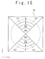
- FIG. 15 is a plan view of a birefringence compensating element used in a seventh exemplary embodiment of the optical head apparatus of the present invention.
- FIG. 16 is a plan view of a birefringence compensating element used in an eighth exemplary embodiment of the optical head apparatus of the present invention.
- FIG. 17 is a view showing a calculation example of the relation between the value of in-plane birefringence and the sum signal level with the value of the vertical birefringence used as a parameter;
- FIG. 18 is a view showing a calculation example of the relation between the value of in-plane birefringence and the push-pull signal with the value of vertical birefringence used as a parameter;
- FIG. 19 is a view showing a calculation example of the relation between the value of in-plane birefringence and the push-pull signal modulation factor with the value of vertical birefringence used as a parameter;
- FIG. 20 is a view showing a calculation example of the relation between the value of in-plane birefringence and the DPD signal amplitude with the value of vertical birefringence used as a parameter;
- FIG. 21 is a plan view of a birefringence compensating element used in a ninth exemplary embodiment of the optical head apparatus of the present invention.
- FIG. 22 is a plan view of a birefringence compensating element used in a tenth exemplary embodiment of the optical head apparatus of the present invention.
- FIG. 23 is a view showing a calculation example of the relation between the duty ratio of the grating and the effective refractive index, in the birefringence compensating element used in the ninth and tenth exemplary embodiments of the optical head apparatus of the present invention.
- FIGS. 24A to 24D are sectional views of the birefringence compensating element used in the ninth and tenth exemplary embodiments of the optical head apparatus of the present invention.
- FIG. 25 is a view showing a configuration of an optical information recording reproducing apparatus according to exemplary embodiments of the optical information recording/reproducing apparatus of the present invention.
- FIG. 26 is a view showing the configuration of the conventional typical optical head apparatus
- FIG. 27 is a view showing the relation between the optical recording medium and the XYZ-coordinates
- FIG. 28 is a view showing the calculation example of the relation between the value of in-plane birefringence and the sum signal level with the value of the vertical birefringence used as a parameter;
- FIG. 29 is a view showing the calculation example of the relation between the value of in-plane birefringence and the push-pull signal amplitude with the value of the vertical birefringence used as a parameter;
- FIG. 30 is the view showing the calculation example of the relation between the value of in-plane birefringence and the push-pull signal modulation factor with the value of the vertical birefringence used as a parameter;
- FIG. 31 is a view showing the calculation example of the relation between the value of in-plane birefringence and the DPD signal amplitude with the value of the vertical birefringence used as a parameter.
- FIG. 25 shows the configuration of an optical information recording reproducing apparatus according to an exemplary embodiment of the optical information recording/reproducing apparatus of the present invention.
- the optical information recording reproducing apparatus is provided with a controller 39 , a modulating circuit 40 , a record signal generating circuit 41 , a semiconductor laser driving circuit 42 , an amplifying circuit 43 , a reproduced signal processing circuit 44 , a decoding circuit 45 , an error signal generating circuit 46 , an objective lens driving circuit 47 and an optical head apparatus 50 .
- the modulating circuit 40 modulates data to be recorded to the disc 7 , in accordance with a modulation scheme.
- the record signal generating circuit 41 generates a record signal for driving the semiconductor laser 1 within the optical head apparatus 50 in accordance with a record strategy, on the basis of the signal modulated by the modulating circuit 40 .
- the semiconductor laser driving circuit 42 supplies a current in response to the record signal to the semiconductor laser 1 , on the basis of the record signal generated by the record signal generating circuit 41 to drive the semiconductor laser 1 . This achieves data recording onto the disc 7 .
- the amplifying circuit 43 amplifies the outputs from light receiving units within the photo-detector 10 provided in the optical head apparatus 50 .
- the reproduced signal processing circuit 44 provides RF signal generation, waveform equalization and binarization on the basis of the signal amplified by the amplifying circuit 43 .
- the decoding circuit 45 decodes the signal binarized in the reproduced signal processing circuit 44 , in accordance with a demodulation scheme. This achieves data reproduction from the disc 7 .
- the error signal generating circuit 46 generates a focus error signal and a track error signal on the basis of the signal amplified by the amplifying circuit 43 .
- the objective lens driving circuit 47 supplies currents corresponding to the focus error signal and the track error signal to an actuator (not shown) which drives the objective lens 6 , to drive the objective lens 6 .
- the optical system other than the disc 7 is driven in the radius direction of the disc 7 by a positioner (not shown), and the disc 7 is driven and rotated by a spindle (not shown). This provides the focus, track, positioner and spindle servo controls.
- the circuits related to the data recording between the modulating circuit 40 and the semiconductor laser driving circuit 42 , the circuits related to the data reproduction between the amplifying circuit 43 and the decoding circuit 45 , and the circuits related to the servo controls between the amplifying circuit 43 and the objective lens driving circuit 47 are controlled by the controller 39 .
- This exemplary embodiment is implemented as optical information recording reproducing apparatus which carries out the recording onto and the reproduction from the disc 7 .
- an exemplary embodiment of the optical information recording/reproducing apparatus of the present invention may be implemented as a read-only optical information apparatus which carries out only the reproduction from the disc 7 .
- the semiconductor laser 1 is not driven by the semiconductor laser driving circuit 42 in accordance with the record signal; instead, the semiconductor laser 1 is driven so that the power of output light is kept at a constant value.
- FIG. 1 shows the configuration of the optical head apparatus 50 .
- the optical head apparatus 50 is provided with a semiconductor laser 1 , a collimator lens 2 , a polarizing beam splitter 3 , a quarter-wave plate 4 , a birefringence compensating element 5 , an objective lens 6 , a cylindrical lens 8 , a convex lens 9 and a photo-detector 10 .
- the output light emitted by the semiconductor laser 1 which serves as a light source, is collimated by the collimator lens 2 .
- the collimated light enters into the polarizing beam splitter 3 as a P-polarized light, and almost 100% thereof enters the quarter-wave plate 4 after passing through the polarizing beam splitter 3 .
- the quarter-wave plate 4 converts the incoming light from linear to circular polarized light when the incoming light passes therethrough.
- the circular polarized light is focused by the objective lens 6 onto the disc 7 , which is a sort of optical recording medium.
- the reflected light reflected by the disc 7 passes through the objective lens 6 in the opposite direction and enters the quarter-wave plate 4 .
- the quarter-wave plate 4 converts the incoming light from circular to linear polarized light when the incoming light passes therethrough.
- the direction of polarization of the linear-polarized light on this return path is orthogonal to that of the linear-polarized light on the outward path.
- the linear-polarized light enters the polarizing beam splitter 3 as an S-polarized light, and almost 100% thereof enters the cylindrical lens 8 , after being reflected. This light passes through the cylindrical lens 8 and the convex lens 9 and is received by the photo-detector 10 .
- the photo-detector 10 is placed at the middle between the two focal lines of the cylindrical lens 8 and the convex lens 9 .
- the photo-detector 10 includes four light receiving units separated by a division line in the direction corresponding to the radius direction of the disc 7 and a division line in the direction corresponding to the tangential direction.
- the focus error signal is obtained by an astigmatism technique, while the track error signal and the RF signal are obtained based on a push-pull method or a DPD method.
- a birefringence compensating element 5 a is used as the birefringence compensating element 5 within the optical head apparatus 50 , the configuration of which is shown in FIG. 1 .
- FIG. 2 is a plan view of the birefringence compensating element 5 a .
- the birefringence compensating element 5 a is divided into four regions (denoted by the suffixes a to d) at intervals of 90° in the tangential direction with two straight lines which cross the beam axis. Moreover, each region is divided into four regions (denoted by the numerals 11 to 14 ) in the radius direction by three concentric circles whose centers are located on the beam axis.
- the groups of regions quartered at intervals of 90° in the tangential direction namely, the groups of regions to which a to d are attached as the suffixes are referred to as the region groups a to d.
- the groups of regions quartered in the radius direction namely, the groups of regions to which the numerals “ 11 ” to “ 14 ” are assigned are referred to as the region groups 11 to 14 .
- the dashed line on the drawing indicates the effective diameter of the objective lens 6 .
- the directions of the x-axis and the y-axis shown in the drawing correspond to the radius and tangential directions of the disc 7 , respectively.
- the birefringence compensating element 5 a includes members each of which exhibits uniaxial anisotropy in the refractive index.
- the arrows in the drawing indicate the directions of the optic axes of these members in the respective regions.
- the optic axes in the region groups a and c are directed in the directions of 0° with respect to the x-axis in the drawing.
- the optic axes in the region groups b and d are directed in the directions of 90° with respect to the x-axis in the drawing.
- the absolute values of the optical phase differences between the polarization components in the directions parallel and vertical to the optic axis are 0° in the region group 11 , 18° in the region group 12 , 36° in the region group 13 , and 54° in the region group 14 .
- the design of the birefringence compensating element 5 a will be described later.
- a birefringence compensating element 5 b is used as the birefringence compensating element 5 in the optical head apparatus 50 , the configuration which is shown in FIG. 1 .
- FIG. 3 is the plan view of the birefringence compensating element 5 b .
- the birefringence compensating element 5 b is divided into four regions (denoted by the suffixes a to d) at intervals of 90° in the tangential direction by two straight lines which cross the beam axis. Each region is divided into four regions (denoted by the numerals 15 to 18 ) in the radius direction by the three concentric circles whose centers are located on the beam axis.
- the groups of regions quartered at intervals of 90° in the tangential direction namely, the groups of regions to which a to d are attached as the suffixes are referred as the region groups a to d.
- the groups of regions quartered in the radius direction namely, the groups of regions to which the numerals “ 15 ” to “ 18 ” are assigned are referred to as the region groups 15 to 18 .
- the dashed line on the drawing indicates the effective diameter of the objective lens 6 .
- the directions of the x-axis and the y-axis shown in the drawing correspond to the radius and tangential directions of the disc 7 , respectively.
- the birefringence compensating element 5 b includes members each of which exhibits uniaxial anisotropy in the refractive index.
- the arrows in the drawing indicate the directions of the optic axes of these members in the respective regions.
- the optic axes in the region groups a and c are directed in the directions of 90° with respect to the x-axis in the drawing.
- the optic axes in the region groups b and d are directed in the directions of 0° with respect to the x-axis in the drawing.
- the absolute values of the optical phase differences between the polarization components in the directions parallel and vertical to the optic axis are 0° in the region group 15 , 18° in the region group 16 , 36° in the region group 17 , and 54° in the region group 18 .
- the design of the birefringence compensating element 5 b will be described later.
- a birefringence compensating element 5 c is used as the birefringence compensating element 5 in the optical head apparatus 50 , the configuration of which is shown in FIG. 1 .
- FIG. 4 is the plan view of the birefringence compensating element 5 c .
- the birefringence compensating element 5 c is divided into eight regions (denoted by the suffixes a to h) at intervals of 45° in the tangential direction by four straight lines which cross the beam axis. Each region is divided into four regions (denoted by the numerals 19 to 22 ) in the radius direction by the three concentric circles whose centers are located on the beam axis.
- the groups of regions quartered at intervals of 45° in the tangential direction namely, the groups of regions to which a to h are attached as the suffixes are referred as the region groups a to h.
- the groups of regions quartered in the radius direction namely, the groups of regions to which the numerals “ 19 ” to “ 22 ” are assigned are referred to as the region groups 19 to 22 .
- the dashed line on the drawing indicates the effective diameter of the objective lens 6 .
- the directions of the x-axis and the y-axis shown in the drawing correspond to the radius and tangential directions of the disc 7 , respectively.
- the birefringence compensating element 5 c includes members each of which exhibits uniaxial anisotropy in the refractive index.
- the arrows in the drawing indicate the directions of the optic axes of these members in the respective regions.
- the optic axes in the region groups a and c are directed in the directions of 0° with respect to the x-axis in the drawing.
- the optic axes in the region groups b and d are directed in the directions of 90° with respect to the x-axis in the drawing.
- the optic axes in the region groups e and g are directed in the directions of 45° with respect to the x-axis in the drawing.
- the optic axes in the region groups f and h are directed in the directions of 135° with respect to the x-axis in the drawing.
- the absolute values of the optical phase differences between the polarization components in the directions parallel and vertical to the optic axis are 0° in the region group 19 , 18° in the region group 20 , 36° in the region group 21 , and 54° in the region group 22 .
- the design of the birefringence compensating element 5 c will be described later.
- a birefringence compensating element 5 d is used as the birefringence compensating element 5 in the optical head apparatus 50 , the configuration of which is shown in FIG. 1 .
- FIG. 5 is the plan view of the birefringence compensating element 5 d .
- the birefringence compensating element 5 d is divided into eight regions (denoted by the suffixes a to h) at intervals of 45° in the tangential direction by four straight lines which cross the beam axis. Each region is divided into four regions (denoted by the numerals 23 to 26 ) in the radius direction by the three concentric circles whose centers are located on the beam axis.
- the groups of regions quartered at intervals of 45° in the tangential direction namely, the groups of regions to which a to h are attached as the suffixes are referred as the region groups a to h.
- the groups of regions quartered in the radius direction namely, the groups of regions to which the numerals “ 23 ” to “ 26 ” are assigned are referred to as the region groups 23 to 26 .
- the dashed line on the drawing indicates the effective diameter of the objective lens 6 .
- the directions of the x-axis and the y-axis shown in the drawing correspond to the radius and tangential directions of the disc 7 , respectively.
- the birefringence compensating element 5 d includes members each of which exhibits uniaxial anisotropy in the refractive index.
- the arrows in the drawing indicate the directions of the optic axes of these members in the respective regions.
- the optic axes in the region groups a and c are directed in the directions of 90° with respect to the x-axis in the drawing.
- the optic axes in the region groups b and d are directed in the directions of 0° with respect to the x-axis in the drawing.
- the optic axes in the region groups e and g are directed in the directions of 135° with respect to the x-axis in the drawing.
- the optic axes in the region groups f and h are directed in the directions of 45° with respect to the x-axis in the drawing.
- the absolute values of the optical phase differences between the polarization components in the directions parallel and vertical to the optic axis are 0° in the region group 23 , 18° in the region group 24 , 36° in the region group 25 , and 54° in the region group 26 .
- the design of the birefringence compensating element 5 d will be described later.
- ⁇ tan - 1 ⁇ y x [ Equation ⁇ ⁇ 2 ]
- ⁇ is the optical phase difference between the polarization component in the major axis direction of the ellipse and the polarization component in the minor axis direction
- ⁇ is the angle representing the major axis direction or minor axis direction of the ellipse.
- the compensation of the vertical birefringence of the protective layer of the disc 7 can be achieved by fulfilling the requirement that the Jones matrix B of the birefringence compensating element 5 is the inverse matrix of the Jones matrix S of the protective layer of the disc 7 for the case of the non-existence of the vertical birefringence.
- the birefringence compensating element 5 is formed as a wavelength plate for which the direction of the optic axis is determined by ⁇ + ⁇ and the optical phase difference between the polarization components in the directions parallel and vertical to the optic axis is defined by ⁇ .
- the direction of the optic axis and the optical phase difference varies depending on the in-plane position of the birefringence compensating element 5 , since ⁇ + ⁇ and ⁇ are the functions of x and y. This allows cancelling the optical phase difference caused by the light passing through the protective layer of the disc 7 with the optical phase difference caused by the light passing through the birefringence compensating element 5 .
- the calculation of the direction of the optic axis concludes that the direction of the optic axis is rotationally symmetrical with respect to the beam axis, directed in the radius direction or the tangential direction of the circle with center at the beam axis. That is, the direction of the optic axis continuously varies in accordance with the angle with respect to the x-axis shown in FIG. 2 to FIG. 5 . In an actual implementation, the directions of the optic axis may vary-discretely as shown in FIG. 2 to FIG. 5 , rather than vary continuously as mentioned above.
- the design in which the direction of the beam axis discretely varies provides easy manufacture for the birefringence compensating element, although the effect of the compensation for the vertical birefringence is slightly reduced.
- the direction of the optic axis discretely varies depending on the angle with respect to the x-axis over the four regions divided in the tangential direction.
- the direction of the optic axis is in the radius direction of the circle with center at the beam axis at the centers of the regions groups a, b, c and d.
- the direction of the optic axis is shifted from the radius direction of the circle with center at the beam axis with a larger shifting, as it goes from the center of each region group to the boundary with the adjacent region group.
- the direction of the optic axis discretely varies depending on the angle with respect to the x-axis over the four regions divided in the tangential direction.
- the direction of the optic axis is in the tangential direction of the circle with center at the beam axis at the centers of the regions groups a, b, c and d.
- the direction of the optic axis is shifted from the tangential direction of the circle with center at the beam axis with a larger shifting, as it goes from the center of each region group to the boundary with the adjacent region group.
- the direction of the optic axis discretely varies depending on the angle with respect to the x-axis over the eight regions divided in the tangential direction.
- the direction of the optic axis is in the radius direction of the circle with center at the beam axis at the centers of the regions groups a, b, c, d, e, f, g, and h.
- the direction of the optic axis is shifted from the radius direction of the circle with center at the beam axis with a larger shifting, as it goes from the center of each region group to the boundary with the adjacent region group.
- the direction of the optic axis discretely varies depending on the angle with respect to the x-axis over the eight regions divided in the tangential direction.
- the direction of the optic axis is in the tangential direction of the circle with center at the beam axis at the centers of the regions groups a, b, c, d, e, f, g, and h.
- the direction of the optic axis is shifted from the tangential direction of the circle with center at the beam axis with a larger shifting, as it goes from the center of each region group to the boundary with the adjacent region group.
- FIG. 6 and FIG. 7 show calculation examples of the optical phase difference between the polarization components in the directions parallel and vertical to the optic axis in the birefringence compensating element.
- the optical phase difference varies continuously in the fashion of a quadratic function in accordance the distance from the beam axis.
- the optical phase difference may discretely vary, instead of continuously as mentioned above.
- the design in which the optical phase difference discretely varies provides easy manufacture for the birefringence compensating element, although the effect of the compensation for the vertical birefringence is slightly reduced.
- the optical phase difference discretely varies over the four regions divided in the radius direction in accordance with the distance from the beam axis, as indicated by the dashed lines in FIG. 6 and FIG. 7 .
- the absolute value of the optical phase difference is 0° in the region groups 11 , 15 , 19 and 23 , 18° in the region groups 12 , 16 , 20 and 24 , 36° in the region groups 13 , 17 , 21 and 25 , and 54° in the region groups 14 , 18 , 22 and 26 .
- the boundary between the regions with the absolute values of the optical phase differences of 0° and 18° has a radius of 0.75 mm
- the boundary between the regions with the absolute values of the optical phase differences of 18° and 36° has a radius of 1.28 mm
- the boundary between the regions with the absolute values of the optical phase differences of 36° and 54° has a radius of 1.64 mm.
- the compensation of the vertical birefringence requires a negative optical phase difference in the right and left regions, and the positive optical phase difference in the upper and lower regions, where the optical phase difference is defined to be positive when the phase of the polarization component in the x-axis direction leads ahead of the phase of the polarization component in the y-axis direction, and the optical phase difference is defined to be negative when the phase of the polarization component in the x-axis direction lags behind the phase of the polarization component in the y-axis direction.
- Liquid crystal polymer is used as the members with the uniaxial anisotropy of refractive index within the birefringence compensating elements 5 a to 5 d .
- the liquid crystal polymer usually has a nature of the positive crystal, exhibiting a larger refractive index for the polarization component in the direction parallel to the optic axis than that for the polarization component in the direction vertical to the optic axis.
- the phase of the polarization component in the direction parallel to the optic axis lags behind that of the polarization component in the direction vertical to the optic axis.
- the phase lagging of the polarization component in the direction parallel to the optic axis with respect to the polarization component vertical to the optic axis should be increased from the inside to the outside in order to satisfy the foregoing conditions.
- the optical phase difference depicted in the vertical axis in FIG. 6 represents the phase lagging for this situation.
- the phase lagging should be varied from 0° to 18°, to 36° and to 54° as indicated by the dashed lines in FIG. 6 .
- the phase leading of the polarization component in the direction parallel to the optic axis with respect to the polarization component vertical to the optic axis may be increased from the inside to the outside in order to satisfy the foregoing conditions. Since the phase cannot be led in an actual implementation, however, the phase lagging may be decreased instead.
- the optical phase difference depicted in the vertical axis in FIG. 7 represents the phase lagging for this situation.
- the phase lagging may be varied from 0° to ⁇ 18°, to ⁇ 36° and to ⁇ 54°; however, the phase lagging cannot be negative in the actual implementation, and therefore the phase lagging may be varied from 360° to 342°, to 324° and to 306° instead as indicated by the dashed lines in FIG. 7 . This makes use of the fact that 0° and 360° are equivalent to each other.
- FIGS. 8A to 8D are sectional views of the birefringence compensating elements 5 a to 5 d .
- the birefringence compensating elements 5 a to 5 d are structured so that liquid crystal polymer 28 having the uniaxial anisotropy in the refractive index is disposed between glass substrates 27 a and 27 b .
- the arrows on the drawings indicate the longitudinal directions of the liquid crystal polymer 28 .
- the directions of the optic axes in the birefringence compensating elements 5 a to 5 d are determined as the projection of the longitudinal direction of the liquid crystal polymer 28 to the in-plane direction.
- the optical phase difference in the birefringence compensating elements 5 a to 5 d is determined in accordance with the angle between the longitudinal direction of the liquid crystal polymer 28 and the in-plane direction.
- the angle between the longitudinal direction of the liquid crystal polymer 28 and the in-plane direction is decreased as it goes from FIGS. 8A to 8D , while the optical phase difference is increased.
- the projection to the in-plane direction of the longitudinal direction of the liquid crystal polymer 28 is placed into a predetermined state so that the direction of the optic axis is directed in the direction of 0° with respect to the x-axis.
- the projection to the in-plane direction of the longitudinal direction of the liquid crystal polymer 28 is placed into a predetermined state so that the direction of the optic axis is directed in the direction of 90° with respect to the x-axis.
- the angle between the longitudinal direction of the liquid crystal polymer 28 and the in-plane direction is placed into a predetermined state so that the optical phase difference is adjusted to 0°.
- the angle between the longitudinal direction of the liquid crystal polymer 28 and the in-plane direction is placed into a predetermined state so that the optical phase difference is adjusted to 18°.
- the angle between the longitudinal direction of the liquid crystal polymer 28 and the in-plane direction is placed into a predetermined state so that the optical phase difference is adjusted to 36°.
- the angle between the longitudinal direction of the liquid crystal polymer 28 and the in-plane direction is placed into a predetermined state so that the optical phase difference is adjusted to 54°.
- the angle between the longitudinal direction of the liquid crystal polymer 28 and the in-plane direction is varied from the state shown in FIG. 8A to the state shown in FIG. 8D , as the optical phase difference is increased from 0°, to 18°, to 36° and to 54°.
- the projection to the in-plane direction of the longitudinal direction of the liquid crystal polymer 28 is placed into a predetermined state so that the direction of the optic axis is directed in the direction of 90° with respect to the x-axis.
- the projection to the in-plane direction of the longitudinal direction of the liquid crystal polymer 28 is placed into a predetermined state so that the direction of the optic axis is directed in the direction of 0° with respect to the x-axis.
- the angle between the longitudinal direction of the liquid crystal polymer 28 and the in-plane direction is placed into a predetermined state so that the optical phase difference is adjusted to 360°.
- the angle between the longitudinal direction of the liquid crystal polymer 28 and the in-plane direction is placed into a predetermined state so that the optical phase difference is adjusted to 342°.
- the angle between the longitudinal direction of the liquid crystal polymer 28 and the in-plane direction is placed into a predetermined state so that the optical phase difference is adjusted to 324°.
- the angle between the longitudinal direction of the liquid crystal polymer 28 and the in-plane direction is placed into a predetermined state so that the optical phase difference is adjusted to 306°.
- the angle between the longitudinal direction of the liquid crystal polymer 28 and the in-plane direction is varied from the state shown in FIG. 8D to the state shown in FIG. 8A , as the optical phase difference is decreased from 360°, to 342°, to 324° and to 306°.
- the projection to the in-plane direction of the longitudinal direction of the liquid crystal polymer 28 is placed into a predetermined state so that the direction of the optic axis is directed in the direction of 0° with respect to the x-axis.
- the projection to the in-plane direction of the longitudinal direction of the liquid crystal polymer 28 is placed into a predetermined state so that the direction of the optic axis is directed in the direction of 90° with respect to the x-axis.
- the projection to the in-plane direction of the longitudinal direction of the liquid crystal polymer 28 is placed into a predetermined state so that the direction of the optic axis is directed in the direction of 45° with respect to the x-axis.
- the projection to the in-plane direction of the longitudinal direction of the liquid crystal polymer 28 is placed into a predetermined state so that the direction of the optic axis is directed in the direction of 135° with respect to the x-axis.
- the angle between the longitudinal direction of the liquid crystal polymer 28 and the in-plane direction is placed into a predetermined state so that the optical phase difference is adjusted to 0°.
- the angle between the longitudinal direction of the liquid crystal polymer 28 and the in-plane direction is placed into a predetermined state so that the optical phase difference is adjusted to 18°.
- the angle between the longitudinal direction of the liquid crystal polymer 28 and the in-plane direction is placed into a predetermined state so that the optical phase difference is adjusted to 36°.
- the angle between the longitudinal direction of the liquid crystal polymer 28 and the in-plane direction is placed into a predetermined state so that the optical phase difference is adjusted to 54°.
- the angle between the longitudinal direction of the liquid crystal polymer 28 and the in-plane direction is varied from the state shown in FIG. 8A to the state shown in FIG. 8D , as the optical phase difference is increased from 0°, to 18°, to 36° and to 54°.
- the projection to the in-plane direction of the longitudinal direction of the liquid crystal polymer 28 is placed into a predetermined state so that the direction of the optic axis is directed in the direction of 90° with respect to the x-axis.
- the projection to the in-plane direction of the longitudinal direction of the liquid crystal polymer 28 is placed into a predetermined state so that the direction of the optic axis is directed in the direction of 0° with respect to the x-axis.
- the projection to the in-plane direction of the longitudinal direction of the liquid crystal polymer 28 is placed into a predetermined state so that the direction of the optic axis is directed in the direction of 135° with respect to the x-axis.
- the projection to the in-plane direction of the longitudinal direction of the liquid crystal polymer 28 is placed into a predetermined state so that the direction of the optic axis is directed in the direction of 45° with respect to the x-axis.
- the angle between the longitudinal direction of the liquid crystal polymer 28 and the in-plane direction is placed into a predetermined state so that the optical phase difference is adjusted to 360°.
- the angle between the longitudinal direction of the liquid crystal polymer 28 and the in-plane direction is placed into a predetermined state so that the optical phase difference is adjusted to 342°.
- the angle between the longitudinal direction of the liquid crystal polymer 28 and the in-plane direction is placed into a predetermined state so that the optical phase difference is adjusted to 324°.
- the angle between the longitudinal direction of the liquid crystal polymer 28 and the in-plane direction is placed into a predetermined state so that the optical phase difference is adjusted to 306°.
- the angle between the longitudinal direction of the liquid crystal polymer 28 and the in-plane direction is varied from the state shown in FIG. 8D to the state shown in FIG. 8A , as the optical phase difference is decreased from 360°, to 342°, to 324° and to 306°.
- Equation ⁇ ⁇ 3 E0(x,y) is the electric field distribution of the output light from the semiconductor laser 1 and Q is the Jones matrix of the quarter-wave plate 4 .
- Q is given by the following equation:
- the electric field distribution of the reflected light from the disc 7 is represented by the following equation by using the Jones vector.
- L is given by the following equation: L ⁇
- La and Lb are obtained by the integrations given in the Equation 8 in the ranges of x ⁇ 0 and x>0, respectively, where La and Lb are the light amounts on the photo-detector 10 corresponding to the two regions.
- the sum signal is given by La+Lb
- the push-pull signal is given by La ⁇ Lb.
- La, Lb, Lc and Ld are obtained by the integrations given in the Equation 8 in the range of x ⁇ 0 and y ⁇ 0, the range of x>0 and y ⁇ 0, the range of x>0 and y>0 and the range of x ⁇ 0 and y>0, respectively, where La and Lc are the light amounts on the photo-detector 10 corresponding to the two regions positioned at one set of opposite angles and Lb an Ld are the light amounts on the photo-detector 10 corresponding to the two regions positioned at the other set of opposite angles.
- the DPD signal is given by the temporal difference between (La+Lc) and (Lb+Ld).
- the relation of the birefringence of the protective layer of the optical recording medium to the DPD signal amplitude can be calculated in accordance with this equation, for the case that the focused spot on the optical recording medium crosses a pit on the optical recording medium.
- FIG. 9 shows a calculation example of the relation of the value of in-plane birefringence to the sum signal level with the value of vertical birefringence used as a parameter
- FIG. 10 shows a calculation example of the relation of the value of in-plane birefringence to the push-pull signal amplitude with the value of vertical birefringence used as a parameter
- FIG. 11 shows a calculation example of the relation of the value of in-plane birefringence to the push-pull signal modulation factor with the value of vertical birefringence used as a parameter, which is obtained from the sum signal level shown in FIG.
- FIG. 9 and the push-pull signal amplitude shown in FIG. 10 .
- the calculation conditions are same as the conditions described with respect to FIGS. 28 to 30 .
- the vertical axes of FIG. 9 and FIG. 10 are standardized by the sum signal level for the case that the groove is not formed on the optical recording medium.
- the black circles on the drawings indicate the calculation result for the value of vertical birefringence being 0, and the white circles on the drawings indicate the calculation result for the value of the vertical birefringence being 7 ⁇ 10 ⁇ 4 without the compensation by the birefringence compensating element 5 . These results are same to those shown in FIGS. 28 to 30 .
- the symbols ⁇ on the drawings indicate the calculation result for the value of vertical birefringence being 7 ⁇ 10 ⁇ 4 with the compensation by the birefringence compensating element 5 a or 5 b , which is comprised of the four regions divided in the tangential direction as shown in FIG. 2 and FIG. 3 .
- the symbols ⁇ on the drawings indicate the calculation result for the value of vertical birefringence being 7 ⁇ 10 ⁇ 4 with the compensation by the birefringence compensating element 5 c or 5 d , which is comprised of eight regions divided in the tangential direction as shown in FIGS. 4 and 5 .
- the sum signal level shows the maximum value when the value of in-plane birefringence is zero, and the sum signal level decreases with the increase in the absolute value of the value of the in-plane birefringence, for both of the case that the compensation is achieved by the birefringence compensating element 5 ( 5 a , 5 b ) comprised of four regions divided in the tangential direction, and the case that the compensation is achieved by the birefringence compensating element 5 ( 5 c , 5 d ) comprised of eight regions divided in the tangential direction, similarly to the case without the vertical birefringence.
- the push-pull signal amplitude shows the maximum value at a value of in-plane birefringence slightly smaller than 0, and the push-pull signal amplitude decreases as the value of in-plane birefringence increases or decreases from that value, for the case that the compensation is achieved by the birefringence compensating element 5 ( 5 a , 5 b ) comprised of four regions divided in the tangential direction.
- the push-pull signal amplitude shows the maximum value at a value of in-plane birefringence slightly larger than 0, and the push-pull signal amplitude decrease as the value of the in-plane birefringence increases or decreases from that value.
- the push-pull signal modulation factor increases monotonously and slightly as the value of the in-plane birefringence is changed from positive to negative value, when the compensation is achieved by the birefringence compensating element 5 ( 5 a , 5 b ) comprised of four regions divided in the tangential direction.
- the push-pull signal modulation factor decreases monotonously and slightly as the value of in-plane birefringence is changed from positive to negative value, when the compensation is achieved by the birefringence compensating element 5 ( 5 c , 5 d ) comprised of eight regions divided in the tangential direction.
- birefringence compensating element 5 suppresses the change in the push-pull signal modulation factor depending on the in-plane position of the optical recording medium.
- Larger suppression effect of the change in the push-pull signal modulation factor is achieved by the birefringence compensating element 5 ( 5 c , 5 d ) comprised of eight regions divided in the tangential direction, as compared with the birefringence compensating element 5 ( 5 a , 5 b ) comprised of four regions divided in the tangential direction.
- FIG. 12 shows a calculation example of the relation of the value of in-plane birefringence to the DPD signal amplitude with the value of vertical birefringence used as a parameter for the respective cases that the birefringence compensating element 5 depicted in the first to fourth exemplary embodiments.
- the calculation conditions are same as the conditions described with respect to FIG. 31 .
- the vertical axis of FIG. 12 is standardized by the duration of the channel clock.
- the black circles on the drawing indicate the calculation result for the value of vertical birefringence being 0, and the white circles on the drawing indicate the calculation result for the value of vertical birefringence being 7 ⁇ 10 ⁇ 4 without the compensation by the birefringence compensating element 5 .
- the symbols ⁇ on the drawing indicate the calculation result for the value of vertical birefringence being 7 ⁇ 10 ⁇ 4 , when the compensation is achieved by the birefringence compensating element 5 a or 5 b , which is comprised of four regions divided in the tangential direction as shown in FIGS. 2 and 3 .
- the symbols ⁇ on the drawing indicate the calculation result for the value of vertical birefringence being 7 ⁇ 10 ⁇ 4 , when the compensation is achieved by the birefringence compensating element 5 c or 5 d , which are comprised of eight regions divided in the tangential direction as shown in FIGS. 4 and 5 .
- the DPD signal amplitude increases monotonously and slightly as the value of in-plane birefringence is changed from positive to negative value, when the compensation is achieved by the birefringence compensating element 5 ( 5 a , 5 b ) comprised of four regions divided in the tangential direction.
- the birefringence compensating element 5 ( 5 c , 5 d ) comprised of eight regions divided in the tangential direction when the compensation is achieved by the birefringence compensating element 5 ( 5 c , 5 d ) comprised of eight regions divided in the tangential direction, on the other hand, the DPD signal amplitude decreases monotonously and slightly as the value of in-plane birefringence is changed from positive value to negative value.
- birefringence compensating element 5 suppresses the change in the DPD signal amplitude depending on the in-plane position of the optical recording medium. Larger suppression effect of the change in the DPD signal amplitude is achieved by the birefringence compensating element 5 ( 5 c , 5 d ) comprised of eight regions divided in the tangential direction, as compared with the birefringence compensating element 5 ( 5 a , 5 b ) comprised of four regions divided in the tangential direction.
- the birefringence compensating elements 5 a and 5 b shown in FIGS. 2 and 3 are divided into the four regions in the tangential direction, and each region is further divided into the four regions in the radius direction.
- the birefringence compensating elements 5 c and 5 d shown in FIGS. 4 and 5 are divided into the eight regions in the tangential direction, and each region is further divided into the four regions in the radius direction.
- the number of the regions divided in the tangential direction in the birefringence compensating element 5 may be arbitrarily selected, not limited to four or eight, and the number of the regions divided in the radius direction may be arbitrarily selected, not limited to four.
- the suppression effect of the changes in the push-pull signal modulation factor and DPD signal amplitude depending on the in-plane position of the optical recording medium is enhanced by the increase in the number of the regions divided in the tangential direction in the birefringence compensating element 5 and by the increase in the number of the regions divided in the radius direction.
- the decreases in the number of the regions divided in the tangential direction in the birefringence compensating element 5 and in the number of the regions divided in the radius direction improves manufacture easiness of the birefringence compensating element 5 .
- the birefringence compensating element 5 e is used as the birefringence compensating element 5 in the optical head apparatus 50 , the configuration of which is shown in FIG. 1 .
- FIG. 13 is a plan view of the birefringence compensating element 5 e .
- the birefringence compensating element 5 e is divided into four regions at intervals of 90° in the tangential direction with two straight lines which cross the beam axis.
- the left and right regions (denoted by suffixes “a” and “c”) out of these four regions are each divided into four regions (denoted by the numerals 29 to 32 ) in the radius direction by three concentric circles with centers at the beam axis.
- the left and right groups of regions namely, the groups of regions to which the suffixes “a” and “c” are attached are referred to as the region groups a and c.
- region groups 29 to 32 a pair of groups of regions quartered in the radius direction, namely, the groups of regions to which the numerals “ 29 ” to “ 32 ” are assigned are referred to as the region groups 29 to 32 .
- the dashed line on the drawing indicates the effective diameter of the objective lens 6 .
- the directions of the x-axis and the y-axis shown in the drawing correspond to the radius and tangential directions of the disc 7 , respectively.
- the birefringence compensating element 5 e includes members each of which exhibits uniaxial anisotropy in the refractive index.
- the arrows in the drawing indicate the directions of the optic axes of these members in the respective regions.
- the optic axes in the region groups a and c are directed in the directions of 0° with respect to the x-axis in the drawing.
- the absolute values of the optical phase differences between the polarization components in the directions parallel and vertical to the optic axis are 0° in the region group 29 , 18° in the region group 30 , 36° in the region group 31 , and 54° in the region group 32 .
- optical phase differences within the region groups 29 to 32 of the birefringence compensating element 5 e are those indicated by the dashed line in FIG. 6 .
- the optical phase differences between the polarization components in the directions parallel and vertical to the optic axis are 0° in the upper and lower regions.
- a birefringence compensating element 5 f is used as the birefringence compensating element 5 in the optical head apparatus 50 , the configuration of which is shown in FIG. 1 .
- FIG. 14 is a plan view of the birefringence compensating element 5 e .
- the birefringence compensating element 5 e is divided into four regions at intervals of 90° in the tangential direction with two straight lines which cross the beam axis.
- the left and right regions (denoted by suffixes “a” and “c”) out of these four regions are each divided into four regions (denoted by the numerals 33 to 36 ) in the radius direction by three concentric circles with centers at the beam axis.
- the left and right groups of regions namely, the groups of regions to which the suffixes “a” and “c” are attached are referred to as the region groups a and c.
- region groups 33 to 36 a pair of groups of regions quartered in the radius direction, namely, the groups of regions to which the numerals “ 33 ” to “ 36 ” are assigned are referred to as the region groups 33 to 36 .
- the dashed line on the drawing indicates the effective diameter of the objective lens 6 .
- the directions of the x-axis and the y-axis shown in the drawing correspond to the radius and tangential directions of the disc 7 , respectively.
- the birefringence compensating element 5 f includes members each of which exhibits uniaxial anisotropy in the refractive index.
- the arrows in the drawing indicate the directions of the optic axes of these members in the respective regions.
- the optic axes in the region groups a and c are directed in the directions of 90° with respect to the x-axis in the drawing.
- the absolute values of the optical phase differences between the polarization components in the directions parallel and vertical to the optic axis are 0° in the region group 33 , 18° in the region group 34 , 36° in the region group 35 , and 54° in the region group 36 .
- optical phase differences within the region groups 33 to 36 of the birefringence compensating element 5 e are those indicated by the dashed line in FIG. 7 .
- the optical phase differences between the polarization components in the directions parallel and vertical to the optic axis are 0° in the upper and lower regions.
- a birefringence compensating element 5 g is used as the birefringence compensating element 5 in the optical head apparatus 50 , the configuration of which is shown in FIG. 1 .
- FIG. 15 is a plan view of the birefringence compensating element 5 g .
- the birefringence compensating element 5 g is divided into four regions at intervals of 90° in the tangential direction with two straight lines which cross the beam axis.
- the upper and lower regions (denoted by suffixes “b” and “d”) out of these four regions are each divided into four regions (denoted by the numerals 29 to 32 ) in the radius direction by three concentric circles with centers at the beam axis.
- the upper and lower groups of regions namely, the groups of regions to which the suffixes “b” and “d” are attached are referred to as the region groups b and d.
- region groups 29 to 32 a pair of groups of regions quartered in the radius direction, namely, the groups of regions to which the numerals “ 29 ” to “ 32 ” are assigned are referred to as the region groups 29 to 32 .
- the dashed line on the drawing indicates the effective diameter of the objective lens 6 .
- the directions of the x-axis and the y-axis shown in the drawing correspond to the radius and tangential directions of the disc 7 , respectively.
- the birefringence compensating element 5 e includes members each of which exhibits uniaxial anisotropy in the refractive index.
- the arrows in the drawing indicate the directions of the optic axes of these members in the respective regions.
- the optic axes in the region groups b and d are directed in the directions of 90° with respect to the x-axis in the drawing.
- the absolute values of the optical phase differences between the polarization components in the directions parallel and vertical to the optic axis are 0° in the region group 29 , 18° in the region group 30 , 36° in the region group 31 , and 54° in the region group 32 .
- optical phase differences within the region groups 29 to 32 of the birefringence compensating element 5 e are those indicated by the dashed line in FIG. 6 .
- the optical phase differences between the polarization components in the directions parallel and vertical to the optic axis are 0° in the left and right regions.
- a birefringence compensating element 5 h is used as the birefringence compensating element 5 in the optical head apparatus 50 , the configuration of which is shown in FIG. 1 .
- FIG. 16 is a plan view of the birefringence compensating element 5 h .
- the birefringence compensating element 5 h is divided into four regions at intervals of 90° in the tangential direction with two straight lines which cross the beam axis.
- the upper and lower regions (denoted by suffixes “b” and “d”) out of these four regions are each divided into four regions (denoted by the numerals 33 to 36 ) in the radius direction by three concentric circles with centers at the beam axis.
- the upper and lower groups of regions namely, the groups of regions to which the suffixes “b” and “d” are attached are referred to as the region groups b and d.
- region groups 33 to 36 a pair of groups of regions quartered in the radius direction, namely, the groups of regions to which the numerals “ 33 ” to “ 36 ” are assigned are referred to as the region groups 33 to 36 .
- the dashed line on the drawing indicates the effective diameter of the objective lens 6 .
- the directions of the x-axis and the y-axis shown in the drawing correspond to the radius and tangential directions of the disc 7 , respectively.
- the birefringence compensating element 5 h includes members each of which exhibits uniaxial anisotropy in the refractive index.
- the arrows in the drawing indicate the directions of the optic axes of these members in the respective regions.
- the optic axes in the region groups b and d are directed in the directions of 0° with respect to the x-axis in the drawing.
- the absolute values of the optical phase differences between the polarization components in the directions parallel and vertical to the optic axis are 0° in the region group 33 , 18° in the region group 34 , 36° in the region group 35 , and 54° in the region group 36 .
- optical phase differences within the region groups 33 to 36 of the birefringence compensating element 5 e are those indicated by the dashed line in FIG. 7 .
- the optical phase differences between the polarization components in the directions parallel and vertical to the optic axis are 0° in the left and right regions.
- the direction of the optic axis is in the radius direction of the circle with center at the beam axis, at the centers of the regions 29 a , 30 a , 31 a and 32 a and at the centers of the regions 29 c , 30 c , 31 c and 32 c .
- the direction of the optic axis is shifted from the radius direction of the circle with center at the beam axis with a larger shifting, as it goes from the center of each region group to the boundary with the upper and lower region groups.
- the direction of the optic axis is in the tangential direction of the circle with center at the beam axis, at the centers of the regions 33 a , 34 a , 35 a and 36 a and at the centers of the regions 33 c , 34 c , 35 c and 36 c .
- the direction of the optic axis is shifted from the tangential direction of the circle with center at the beam axis with a larger shifting, as it goes from the center of each region group to the boundary with the upper and lower region groups.
- the direction of the optic axis is in the radius direction of the circle with center at the beam axis, at the centers of the regions 29 b , 30 b , 31 b and 32 b and at the centers of the regions 29 d , 30 d , 31 d and 32 d .
- the direction of the optic axis is shifted from the radius direction of the circle with center at the beam axis with a larger shifting, as it goes from the center of each region group to the boundary with the left and right region groups.
- the direction of the optic axis is in the tangential direction of the circle with center at the beam axis, at the centers of the regions 33 a , 34 a , 35 a and 36 a and at the centers of the regions 33 c , 34 c , 35 c and 36 c .
- the direction of the optic axis is shifted from the tangential direction of the circle with center at the beam axis with a larger shifting, as it goes from the center of each region group to the boundary with the left and right region groups.
- the phase lagging should be varied from 0° to 18°, to 36° and to 54° as indicated by the dashed lines in FIG. 6 , in order to vary the absolute value of the optical phase difference from 0°, to 18°, to 36° and to 54° in the direction from the inside to the outside.
- the sectional view of the birefringence compensating element 5 e is same as that shown in FIG. 8 .
- the projection of the longitudinal direction of the liquid crystal polymer 28 to the in-plane direction is placed into a predetermined state so that the direction of the optic axis is in the direction of 0° with respect to the x-axis.
- the angle between the longitudinal direction of the liquid crystal polymer 28 and the in-plane direction is placed into a predetermined state so that the optical phase difference is adjusted to 0°.
- the angle between the longitudinal direction of the liquid crystal polymer 28 and the in-plane direction is placed into a predetermined state so that the optical phase difference is adjusted to 18°.
- the angle between the longitudinal direction of the liquid crystal polymer 28 and the in-plane direction is placed into a predetermined state so that the optical phase difference is adjusted to 36°.
- the angle between the longitudinal direction of the liquid crystal polymer 28 and the in-plane direction is placed into a predetermined state so that the optical phase difference is adjusted to 54°.
- the angle between the longitudinal direction of the liquid crystal polymer 28 and the in-plane direction is varied from the state shown in FIG. 8A to the state shown in FIG. 8D , as the optical phase difference is increased from 0°, to 18°, to 36° and to 54°.
- the phase lagging should be varied from 360° to 342°, to 324° and to 306° as indicated by the dashed lines in FIG. 7 , in order to vary the absolute value of the optical phase difference from 0°, to 18°, to 36° and to 54° in the direction from the inside to the outside.
- the sectional view of the birefringence compensating element 5 f is same as that shown in FIG. 8 .
- the projection of the longitudinal direction of the liquid crystal polymer 28 to the in-plane direction is placed into a predetermined state so that the direction of the optic axis is in the direction of 90° with respect to the x-axis.
- the angle between the longitudinal direction of the liquid crystal polymer 28 and the in-plane direction is placed into a predetermined state so that the optical phase difference is adjusted to 360°.
- the angle between the longitudinal direction of the liquid crystal polymer 28 and the in-plane direction is placed into a predetermined state so that the optical phase difference is adjusted to 342°.
- the angle between the longitudinal direction of the liquid crystal polymer 28 and the in-plane direction is placed into a predetermined state so that the optical phase difference is adjusted to 324°.
- the angle between the longitudinal direction of the liquid crystal polymer 28 and the in-plane direction is placed into a predetermined state so that the optical phase difference is adjusted to 306°.
- the angle between the longitudinal direction of the liquid crystal polymer 28 and the in-plane direction is varied from the state shown in FIG. 8D to the state shown in FIG. 8A , as the optical phase difference is increased from 360°, to 342°, to 324° and to 306°.
- the phase lagging should be varied from 0° to 18°, to 36° and to 54° as indicated by the dashed lines in FIG. 6 , in order to vary the absolute value of the optical phase difference from 0°, to 18°, to 36° and to 54° in the direction from the inside to the outside.
- the sectional view of the birefringence compensating element 5 g is same as that shown in FIG. 8 .
- the projection of the longitudinal direction of the liquid crystal polymer 28 to the in-plane direction is placed into a predetermined state so that the direction of the optic axis is in the direction of 90° with respect to the x-axis.
- the angle between the longitudinal direction of the liquid crystal polymer 28 and the in-plane direction is placed into a predetermined state so that the optical phase difference is adjusted to 0°.
- the angle between the longitudinal direction of the liquid crystal polymer 28 and the in-plane direction is placed into a predetermined state so that the optical phase difference is adjusted to 18°.
- the angle between the longitudinal direction of the liquid crystal polymer 28 and the in-plane direction is placed into a predetermined state so that the optical phase difference is adjusted to 36°.
- the angle between the longitudinal direction of the liquid crystal polymer 28 and the in-plane direction is placed into a predetermined state so that the optical phase difference is adjusted to 54°.
- the angle between the longitudinal direction of the liquid crystal polymer 28 and the in-plane direction is varied from the state shown in FIG. 8A to the state shown in FIG. 8D , as the optical phase difference is increased from 0°, to 18°, to 36° and to 54°.
- liquid crystal polymer Used as the members with the uniaxial anisotropy of refractive index within the birefringence compensating element 5 h is liquid crystal polymer, as is the case of the birefringence compensating elements 5 a to 5 d .
- the phase lagging should be varied from 360° to 342°, to 324° and to 306° as indicated by the dashed lines in FIG. 7 , in order to vary the absolute value of the optical phase difference from 0°, to 18°, to 36° and to 54° in the direction from the inside to the outside.
- the sectional view of the birefringence compensating element 5 h is same as that shown in FIG. 8 .
- the projection of the longitudinal direction of the liquid crystal polymer 28 to the in-plane direction is placed into a predetermined state so that the direction of the optic axis is in the direction of 0° with respect to the x-axis.
- the angle between the longitudinal direction of the liquid crystal polymer 28 and the in-plane direction is placed into a predetermined state so that the optical phase difference is adjusted to 360°.
- the angle between the longitudinal direction of the liquid crystal polymer 28 and the in-plane direction is placed into a predetermined state so that the optical phase difference is adjusted to 342°.
- the angle between the longitudinal direction of the liquid crystal polymer 28 and the in-plane direction is placed into a predetermined state so that the optical phase difference is adjusted to 324°.
- the angle between the longitudinal direction of the liquid crystal polymer 28 and the in-plane direction is placed into a predetermined state so that the optical phase difference is adjusted to 306°.
- the angle between the longitudinal direction of the liquid crystal polymer 28 and the in-plane direction is varied from the state shown in FIG. 8D to the state shown in FIG. 8A , as the optical phase difference is increased from 360°, to 342°, to 324° and to 306°.
- FIG. 17 shows a calculation example of the relation of the value of in-plane birefringence to the sum signal level with the value of vertical birefringence used as a parameter
- FIG. 18 shows a calculation example of the relation of the value of in-plane birefringence to the push-pull signal amplitude with the value of vertical birefringence used as a parameter
- FIG. 19 shows a calculation example of the relation of the value of in-plane birefringence to the push-pull signal modulation factor with the value of vertical birefringence used as a parameter, which is obtained from the sum signal level shown in FIG.
- FIG. 17 and the push-pull signal amplitude shown in FIG. 18 The calculation conditions are same as the conditions described with respect to FIGS. 28 to 30 .
- the vertical axes of FIG. 17 and FIG. 18 are standardized by the sum signal level for the case that the groove is not formed on the optical recording medium.
- the black circles on the drawings indicate the calculation result for the value of vertical birefringence being 0, and the white circles on the drawings indicate the calculation result for the value of the vertical birefringence being 7 ⁇ 10 ⁇ 4 without the compensation by the birefringence compensating element 5 . These results are same to those shown in FIGS. 28 to 30 .
- the symbols ⁇ on the drawings indicate the calculation result for the value of vertical birefringence being 7 ⁇ 10 ⁇ 4 with the compensation by the birefringence compensating element 5 e or 5 f shown in FIGS. 13 and 14 with respect to only the left and right regions (only X direction).
- the symbols ⁇ on the drawings indicate the calculation result for the value of vertical birefringence being 7 ⁇ 10 ⁇ 4 with the compensation by the birefringence compensating element 5 g or 5 h shown in FIGS. 15 and 16 with respect to only the upper and lower regions (only Y direction).
- the sum signal level shows the maximum value at a value of in-plane birefringence slightly smaller than zero, and the sum signal level decreases as the value of the in-plane birefringence increases or decreases from that value, for the case that the compensation is achieved by the birefringence compensating element 5 ( 5 e , 5 f ).
- the sum signal level shows the maximum value at a value of in-plane birefringence slightly larger than zero, and the sum signal level decreases as the value of the in-plane birefringence increases or decreases from that value.
- the push-pull signal amplitude shows the maximum value at a value of in-plane birefringence slightly smaller than 0, and the push-pull signal amplitude decreases as the value of in-plane birefringence increases or decreases from that value, for the case that the compensation is achieved by the birefringence compensating element 5 ( 5 e , 5 f ) with respect to only the left and right regions.
- the push-pull signal amplitude monotonously decreases as the value of in-plane birefringence is changed from positive to negative value.
- the push-pull signal modulation factor decreases monotonously and slightly as the value of the in-plane birefringence is changed from positive to negative value, when the compensation is achieved by the birefringence compensating element 5 ( 5 e , 5 f ) only with respect to the left and right regions.
- the push-pull signal modulation factor decreases monotonously in some degree as the value of in-plane birefringence is changed from positive to negative value, when the compensation is achieved by the birefringence compensating element 5 ( 5 g , 5 h ) only with respect to the upper and lower regions.
- birefringence compensating element 5 suppresses the change in the push-pull signal modulation factor depending on the in-plane position of the optical recording medium.
- Larger suppression effect of the change in the push-pull signal modulation factor is achieved by the birefringence compensating element 5 ( 5 e , 5 f ), which provides the compensation only with respect to the left and right regions, as compared with the birefringence compensating element 5 ( 5 g , 5 h ), which provides the compensation only with respect to the upper and lower regions.
- FIG. 20 shows a calculation example of the relation of the value of in-plane birefringence to the DPD signal amplitude with the value of vertical birefringence used as a parameter for the respective cases that the birefringence compensating element 5 depicted in the fifth to eighth exemplary embodiments.
- the calculation conditions are same as the conditions described with respect to FIG. 31 .
- the vertical axis of FIG. 20 is standardized by the duration of the channel clock.
- the black circles on the drawing indicate the calculation result for the value of vertical birefringence being 0, and the white circles on the drawing indicate the calculation result for the value of vertical birefringence being 7 ⁇ 10 ⁇ 4 without the compensation by the birefringence compensating element 5 .
- the symbols ⁇ in the drawing indicate the calculation result for the value of vertical birefringence being 7 ⁇ 10 ⁇ 4 , when the compensation is achieved by the birefringence compensating element 5 e or 5 f shown in FIGS. 13 and 14 with respect to only the left and right regions.
- the symbols in the drawing indicate the calculation result for the value of vertical birefringence being 7 ⁇ 10 ⁇ 4 , when the compensation is achieved by the birefringence compensating element 5 g or 5 h shown in FIGS. 15 and 16 with respect to only the upper and lower regions.
- the DPD signal amplitude slightly increases once as the value of in-plane birefringence is changed from positive to negative value, and then decreases slightly, when the compensation is achieved by the birefringence compensating element 5 ( 5 e , 5 f ) with respect to only the left and right regions.
- the DPD signal amplitude decreases monotonously and slightly as the value of in-plane birefringence is changed from positive value to negative value.
- birefringence compensating element 5 suppresses the change in the DPD signal amplitude depending on the in-plane position of the optical recording medium. Larger suppression effect of the change in the DPD signal amplitude is achieved by the birefringence compensating element 5 ( 5 e , 5 f ), which provides the compensation with respect to only the left and right regions, as compared with the birefringence compensating element 5 ( 5 g , 5 h ), which provides the compensation with respect to only the upper and lower regions.
- the birefringence compensating elements 5 e and 5 f shown in FIGS. 13 and 14 are divided into the four regions in the tangential direction, and the right and left regions of the four regions provide the compensation of the vertical birefringence, while the upper and lower regions do not provide the compensation of the vertical birefringence.
- Each of the right and left regions is further divided into the four regions in the radius direction, with the optic axis directed in the same direction among the regions, and with the different optical phase differences among the regions.
- the 15 and 16 are divided into the four regions in the tangential direction, and the upper and lower regions of the four regions provides the compensation of the vertical birefringence, while the right and left regions do not provide the compensation of the vertical birefringence.
- Each of the upper and lower regions are further divided into the four regions in the radius direction, with the optic axis directed in the same direction among the regions, and with the different optical phase differences among the regions.
- the selection of the regions which provides the compensation of the vertical birefringence in the birefringence compensating element 5 is not limited to the right and left regions or the upper and lower regions, the combination of regions providing the compensation of the vertical birefringence may be arbitrary modified.
- the direction of the optic axis and the optical phase difference in the regions providing the compensation of the vertical birefringence may be same or may be different depending on the in-plane position.
- the effect of the use of the birefringence compensating element 5 for suppressing the changes in the push-pull signal modulation factor and DPD signal amplitude depending on the in-plane position of the optical recording medium is enhanced, as the regions providing the compensation of the vertical birefringence in the birefringence compensating element 5 are positioned closer to the right and left positions.
- the birefringence compensating element 5 i is used as the birefringence compensating element 5 in the optical head apparatus 50 , the configuration of which is shown in FIG. 1 .
- FIG. 21 is the plan view of the birefringence compensating element 5 i .
- the birefringence compensating element 5 i is structured to have a radially-structured grating with center at the beam axis.
- the birefringence compensating element 5 i does not include a member formed of material with uniaxial anisotropy in the refractive index; and the form birefringence is used to provide uniaxial anisotropy in the refractive index for the birefringence compensating element 5 i formed of isotropic material.
- the direction of the optic axis in the birefringence compensating element 5 i is the direction parallel or vertical to the grating.
- radially forming a grating allows directing the direction of the optic axis to the radius direction or the tangential direction of the circle with center at the beam axis in the rotational symmetry with respect to the beam axis.
- radially forming a grating allows successively varying the optic axis.
- the birefringence compensating element 5 j is used as the birefringence compensating element 5 in the optical head apparatus 50 , the configuration of which is shown in FIG. 1 .
- FIG. 22 is a plan view of the birefringence compensating element 5 j .
- the birefringence compensating element 5 j is structured to have a concentric grating with center at the beam axis.
- the birefringence compensating element 5 j does not include a member formed of material with uniaxial anisotropy in the refractive index; and the form birefringence is used to provide uniaxial anisotropy in the refractive index for the birefringence compensating element 5 i formed of isotropic material.
- the direction of the optic axis in the birefringence compensating element 5 i is the direction parallel or vertical to the grating.
- concentrically forming a grating allows directing the direction of the optic axis to the radius direction or the tangential direction of the circle with center at the beam axis in the rotational symmetry with respect to the beam axis.
- concentrically forming a grating allows successively varying the optic axis.
- the grating cycle When the grating cycle is sufficiently smaller as compared with the wavelength of the incoming light, this grating does not refract the incoming light, rather acts as a wavelength plate for the incoming light.
- the refractive indexes of the two media forming the grating are a medium refractive index n 1 and a medium refractive index n 2
- the volume ratios of the respective mediums for one cycle of the grating are q and 1 ⁇ q (q is the duty ratio of the grating)
- the effective refractive indexes for the polarization component in the direction parallel to the grating (the TE polarized component) and the polarization component in the direction vertical to the grating (the TM polarized component) are n i and n v , respectively, n i and n v are given by the following equations:
- n i [ n 1 2 ⁇ q + n 2 2 ⁇ ( 1 - q ) ] 1 2 [ Equation ⁇ ⁇ 9 ]
- n v [ ( 1 n 1 ) 2 ⁇ q + ( 1 n 2 ) 2 ⁇ ( 1 - q ) ] 1 2 [ Equation ⁇ ⁇ 10 ]
- FIG. 23 shows a calculation example of the relation of the duty ration q of the grating to the effective refractive indexes.
- the black circles in the drawing indicate the calculation result of the effective refractive index n i for the polarization component in the direction parallel to the grating (the TE polarized component).
- the white circles in the drawing indicate the calculation result of the effective refractive index n v for the polarization component in the direction vertical to the grating (the TM polarized component).
- FIG. 24 are sectional views of the birefringence compensating elements 5 i and 5 j .
- the birefringence compensating elements 5 i and 5 j are structured in which a grating 38 is formed on a substrate 37 made of quartz.
- the cycle of the grating 38 is denoted by the symbol p, and the height of the grating 38 is denoted by the symbol h.
- the cycle p of the grating 38 is sufficiently short as compared with the wavelength of the incoming light.
- the optical phase differences in the birefringence compensating elements 5 i , 5 j are given as 2 ⁇ h ⁇ n/ ⁇ , where ⁇ is the wavelength of the incoming light.
- the duty ratio of the grating 38 shown in FIG. 24D is 0.45.
- the duty ratio of the grating 38 shown in FIGS. 24A to 24D is increased in this order. Therefore, the optical phase differences in the birefringence compensating elements 5 i and 5 j shown in FIGS. 24A to 24D are increased in this order.
- the birefringence compensating elements 5 i and 5 j can be structured so that the optical phase difference varies continuously in accordance with a quadratic function as indicated by the solid lines in FIGS. 6 and 7 by continuously varying the duty ratio of the grating from 0 to 0.45 depending on the distance from the beam axis.
- the use of the birefringence compensating elements 5 i and 5 j allows perfectly suppressing the changes in the push-pull signal modulation factor and the DPD signal amplitude depending on the in-plane position of the optical recording medium.
Applications Claiming Priority (5)
| Application Number | Priority Date | Filing Date | Title |
|---|---|---|---|
| JP2005314219 | 2005-10-28 | ||
| JP2005-314219 | 2005-10-28 | ||
| JP2006-277256 | 2006-10-11 | ||
| JP2006277256 | 2006-10-11 | ||
| PCT/JP2006/321489 WO2007049738A1 (fr) | 2005-10-28 | 2006-10-27 | Dispositif de tete optique et dispositif d’enregistrement/lecture de donnees optique |
Publications (2)
| Publication Number | Publication Date |
|---|---|
| US20090046548A1 US20090046548A1 (en) | 2009-02-19 |
| US7948854B2 true US7948854B2 (en) | 2011-05-24 |
Family
ID=37967846
Family Applications (1)
| Application Number | Title | Priority Date | Filing Date |
|---|---|---|---|
| US12/091,799 Expired - Fee Related US7948854B2 (en) | 2005-10-28 | 2006-10-27 | Optical head apparatus and optical information recording/reproducing apparatus |
Country Status (3)
| Country | Link |
|---|---|
| US (1) | US7948854B2 (fr) |
| JP (1) | JP4941670B2 (fr) |
| WO (1) | WO2007049738A1 (fr) |
Families Citing this family (5)
| Publication number | Priority date | Publication date | Assignee | Title |
|---|---|---|---|---|
| WO2007105767A1 (fr) * | 2006-03-16 | 2007-09-20 | Asahi Glass Co., Ltd. | Dispositif de tete optique |
| US8287128B2 (en) * | 2009-04-16 | 2012-10-16 | Microvision, Inc. | Laser projection source with polarization diversity element for speckle reduction |
| US8395714B2 (en) * | 2009-04-16 | 2013-03-12 | Microvision, Inc. | Scanned projection system using polymerized liquid crystal layer for speckle reduction |
| KR20110028847A (ko) * | 2009-09-14 | 2011-03-22 | 삼성전자주식회사 | 다분할 편광소자를 갖는 광픽업 장치 |
| US20140222817A1 (en) | 2013-02-04 | 2014-08-07 | David Allen Olsen | System and method for grouping segments of data sequences into clusters |
Citations (45)
| Publication number | Priority date | Publication date | Assignee | Title |
|---|---|---|---|---|
| JPS62248151A (ja) | 1986-04-21 | 1987-10-29 | Hitachi Ltd | 光磁気再生装置 |
| US5195081A (en) | 1988-04-22 | 1993-03-16 | Canon Kabushiki Kaisha | Optical apparatus for effecting recording and/or reproducing of information on/from and optical information recording medium |
| JPH05100114A (ja) | 1991-10-07 | 1993-04-23 | Nitto Denko Corp | 積層波長板及び円偏光板 |
| JPH07318862A (ja) | 1994-05-20 | 1995-12-08 | Hitachi Ltd | 光記録媒体における波面収差の低減方法および光ヘッドおよび光ディスク装置 |
| JPH0981942A (ja) | 1995-09-08 | 1997-03-28 | Mitsubishi Electric Corp | 光ヘッドのトラッキング誤差検出装置 |
| JPH09306054A (ja) | 1996-05-20 | 1997-11-28 | Hitachi Ltd | 光磁気ディスク装置 |
| JPH10124906A (ja) | 1996-10-16 | 1998-05-15 | Sankyo Seiki Mfg Co Ltd | 波長板およびそれを用いた光ピックアップ装置 |
| JPH1173658A (ja) | 1997-06-30 | 1999-03-16 | Matsushita Electric Ind Co Ltd | 光学ヘッド及び、情報記録・再生装置 |
| JPH11219529A (ja) | 1997-10-20 | 1999-08-10 | Samsung Electro Mech Co Ltd | 光ピックアップ装置 |
| JP2000076688A (ja) | 1998-08-27 | 2000-03-14 | Ricoh Co Ltd | 多波長光ピックアップ |
| JP2000155979A (ja) | 1998-09-04 | 2000-06-06 | Matsushita Electric Ind Co Ltd | 収差検出装置及び光学情報記録再生装置 |
| JP2000155973A (ja) | 1998-11-18 | 2000-06-06 | Nec Corp | 光ヘッド装置 |
| JP2000182254A (ja) | 1998-12-15 | 2000-06-30 | Pioneer Electronic Corp | ピックアップ装置 |
| JP2001110074A (ja) | 1999-09-16 | 2001-04-20 | Samsung Electronics Co Ltd | 光記録再生機器用エラー信号検出装置及び再生信号検出装置 |
| JP2001155375A (ja) | 1999-11-30 | 2001-06-08 | Asahi Glass Co Ltd | 光ヘッド装置 |
| JP2001236666A (ja) | 1999-12-15 | 2001-08-31 | Nec Corp | 光ヘッド装置及び光学式情報記録再生装置 |
| JP2002092933A (ja) | 2000-07-13 | 2002-03-29 | Sharp Corp | 光ピックアップ |
| US20020041542A1 (en) | 2000-10-10 | 2002-04-11 | Matsushita Electric Industrial Co., Ltd. | Optical head apparatus, optical information recording and reproducing apparatus, method for detecting aberration and method for adjusting optical head apparatus |
| JP2002237085A (ja) | 2001-02-09 | 2002-08-23 | Hitachi Ltd | 光ピックアップおよびそれを用いた光学的情報再生装置または記録装置 |
| JP2002245639A (ja) | 2001-02-16 | 2002-08-30 | Nec Corp | 光ディスク装置 |
| JP2002279683A (ja) | 2001-03-21 | 2002-09-27 | Ricoh Co Ltd | 光ピックアップ装置 |
| US6487160B1 (en) * | 1999-03-18 | 2002-11-26 | Pioneer Corporation | Optical pickup, information recording apparatus and information reproducing apparatus |
| JP2002358677A (ja) | 2001-05-28 | 2002-12-13 | Hitachi Ltd | 光ヘッド及び光ディスク装置 |
| JP2002367197A (ja) | 2001-06-11 | 2002-12-20 | Hitachi Ltd | 光ディスク装置及び光ディスク装置の制御方法 |
| JP2003016672A (ja) | 2001-06-27 | 2003-01-17 | Toshiba Corp | 光ヘッド装置及び光ヘッド制御装置 |
| JP2003045047A (ja) | 2001-07-27 | 2003-02-14 | Pioneer Electronic Corp | 光ピックアップ装置 |
| JP2003051130A (ja) | 2001-05-31 | 2003-02-21 | Nec Corp | 光ヘッド装置および光学式情報記録再生装置 |
| JP2003091856A (ja) | 2001-09-18 | 2003-03-28 | Sony Corp | 光学ピックアップ |
| JP2003132582A (ja) | 2001-10-23 | 2003-05-09 | Fujitsu Ltd | 光情報処理装置 |
| JP2003248118A (ja) | 2002-02-26 | 2003-09-05 | Ricoh Co Ltd | 波長板、波長板ユニット、光ピックアップ装置及び光ディスク装置 |
| JP2003346365A (ja) | 2002-05-23 | 2003-12-05 | Nec Corp | 光ヘッド装置及び光学式情報記録再生装置 |
| JP2004039018A (ja) | 2002-06-28 | 2004-02-05 | Ricoh Co Ltd | 光ピックアップ装置及び光ディスク装置 |
| JP2004069977A (ja) | 2002-08-06 | 2004-03-04 | Asahi Glass Co Ltd | 回折光学素子および光ヘッド装置 |
| JP2004070977A (ja) | 2002-08-01 | 2004-03-04 | Sony Corp | 光ピックアップ及びディスクドライブ装置 |
| US6707773B2 (en) | 2000-04-20 | 2004-03-16 | Nec Corporation | Optical head and optical information recording and playback apparatus |
| JP2004163225A (ja) | 2002-11-12 | 2004-06-10 | Nec Corp | 複屈折特性の測定方法、光記録媒体および光学式情報記録再生装置 |
| JP2005044429A (ja) | 2003-07-28 | 2005-02-17 | Ricoh Co Ltd | 波長板、光ピックアップ装置及び光ディスク装置 |
| US20050199778A1 (en) | 2002-08-23 | 2005-09-15 | Matsushita Electric Industrial Co., Ltd. | Optical pick-up head, optical information apparatus, and optical information reproducing method |
| JP2005317106A (ja) | 2004-04-28 | 2005-11-10 | Nec Corp | 光ヘッド装置および光学式情報記録再生装置 |
| US20050254391A1 (en) | 2004-05-14 | 2005-11-17 | Sanyo Electric Co., Ltd. | Optical pickup device |
| JP2005353187A (ja) | 2004-06-11 | 2005-12-22 | Nec Corp | 光ヘッド装置及び光学式情報記録再生装置 |
| JP2006196156A (ja) | 2005-01-10 | 2006-07-27 | Samsung Electronics Co Ltd | 光情報記録媒体の複屈折補正用の液晶素子及びそれを備える光ピックアップ及び光記録及び/または再生機器 |
| US7548359B2 (en) | 2002-11-13 | 2009-06-16 | Asahi Glass Company, Limited | Double-wavelength light source unit and optical head device having four diffraction gratings |
| US7626900B2 (en) | 2003-09-24 | 2009-12-01 | Sony Corporation | Optical pickup and disk drive apparatus |
| US7643395B2 (en) | 2005-01-19 | 2010-01-05 | Samsung Electronics Co., Ltd. | Diffraction element and optical pick-up apparatus having the same |
-
2006
- 2006-10-27 JP JP2007542679A patent/JP4941670B2/ja not_active Expired - Fee Related
- 2006-10-27 US US12/091,799 patent/US7948854B2/en not_active Expired - Fee Related
- 2006-10-27 WO PCT/JP2006/321489 patent/WO2007049738A1/fr active Application Filing
Patent Citations (45)
| Publication number | Priority date | Publication date | Assignee | Title |
|---|---|---|---|---|
| JPS62248151A (ja) | 1986-04-21 | 1987-10-29 | Hitachi Ltd | 光磁気再生装置 |
| US5195081A (en) | 1988-04-22 | 1993-03-16 | Canon Kabushiki Kaisha | Optical apparatus for effecting recording and/or reproducing of information on/from and optical information recording medium |
| JPH05100114A (ja) | 1991-10-07 | 1993-04-23 | Nitto Denko Corp | 積層波長板及び円偏光板 |
| JPH07318862A (ja) | 1994-05-20 | 1995-12-08 | Hitachi Ltd | 光記録媒体における波面収差の低減方法および光ヘッドおよび光ディスク装置 |
| JPH0981942A (ja) | 1995-09-08 | 1997-03-28 | Mitsubishi Electric Corp | 光ヘッドのトラッキング誤差検出装置 |
| JPH09306054A (ja) | 1996-05-20 | 1997-11-28 | Hitachi Ltd | 光磁気ディスク装置 |
| JPH10124906A (ja) | 1996-10-16 | 1998-05-15 | Sankyo Seiki Mfg Co Ltd | 波長板およびそれを用いた光ピックアップ装置 |
| JPH1173658A (ja) | 1997-06-30 | 1999-03-16 | Matsushita Electric Ind Co Ltd | 光学ヘッド及び、情報記録・再生装置 |
| JPH11219529A (ja) | 1997-10-20 | 1999-08-10 | Samsung Electro Mech Co Ltd | 光ピックアップ装置 |
| JP2000076688A (ja) | 1998-08-27 | 2000-03-14 | Ricoh Co Ltd | 多波長光ピックアップ |
| JP2000155979A (ja) | 1998-09-04 | 2000-06-06 | Matsushita Electric Ind Co Ltd | 収差検出装置及び光学情報記録再生装置 |
| JP2000155973A (ja) | 1998-11-18 | 2000-06-06 | Nec Corp | 光ヘッド装置 |
| JP2000182254A (ja) | 1998-12-15 | 2000-06-30 | Pioneer Electronic Corp | ピックアップ装置 |
| US6487160B1 (en) * | 1999-03-18 | 2002-11-26 | Pioneer Corporation | Optical pickup, information recording apparatus and information reproducing apparatus |
| JP2001110074A (ja) | 1999-09-16 | 2001-04-20 | Samsung Electronics Co Ltd | 光記録再生機器用エラー信号検出装置及び再生信号検出装置 |
| JP2001155375A (ja) | 1999-11-30 | 2001-06-08 | Asahi Glass Co Ltd | 光ヘッド装置 |
| JP2001236666A (ja) | 1999-12-15 | 2001-08-31 | Nec Corp | 光ヘッド装置及び光学式情報記録再生装置 |
| US6707773B2 (en) | 2000-04-20 | 2004-03-16 | Nec Corporation | Optical head and optical information recording and playback apparatus |
| JP2002092933A (ja) | 2000-07-13 | 2002-03-29 | Sharp Corp | 光ピックアップ |
| US20020041542A1 (en) | 2000-10-10 | 2002-04-11 | Matsushita Electric Industrial Co., Ltd. | Optical head apparatus, optical information recording and reproducing apparatus, method for detecting aberration and method for adjusting optical head apparatus |
| JP2002237085A (ja) | 2001-02-09 | 2002-08-23 | Hitachi Ltd | 光ピックアップおよびそれを用いた光学的情報再生装置または記録装置 |
| JP2002245639A (ja) | 2001-02-16 | 2002-08-30 | Nec Corp | 光ディスク装置 |
| JP2002279683A (ja) | 2001-03-21 | 2002-09-27 | Ricoh Co Ltd | 光ピックアップ装置 |
| JP2002358677A (ja) | 2001-05-28 | 2002-12-13 | Hitachi Ltd | 光ヘッド及び光ディスク装置 |
| JP2003051130A (ja) | 2001-05-31 | 2003-02-21 | Nec Corp | 光ヘッド装置および光学式情報記録再生装置 |
| JP2002367197A (ja) | 2001-06-11 | 2002-12-20 | Hitachi Ltd | 光ディスク装置及び光ディスク装置の制御方法 |
| JP2003016672A (ja) | 2001-06-27 | 2003-01-17 | Toshiba Corp | 光ヘッド装置及び光ヘッド制御装置 |
| JP2003045047A (ja) | 2001-07-27 | 2003-02-14 | Pioneer Electronic Corp | 光ピックアップ装置 |
| JP2003091856A (ja) | 2001-09-18 | 2003-03-28 | Sony Corp | 光学ピックアップ |
| JP2003132582A (ja) | 2001-10-23 | 2003-05-09 | Fujitsu Ltd | 光情報処理装置 |
| JP2003248118A (ja) | 2002-02-26 | 2003-09-05 | Ricoh Co Ltd | 波長板、波長板ユニット、光ピックアップ装置及び光ディスク装置 |
| JP2003346365A (ja) | 2002-05-23 | 2003-12-05 | Nec Corp | 光ヘッド装置及び光学式情報記録再生装置 |
| JP2004039018A (ja) | 2002-06-28 | 2004-02-05 | Ricoh Co Ltd | 光ピックアップ装置及び光ディスク装置 |
| JP2004070977A (ja) | 2002-08-01 | 2004-03-04 | Sony Corp | 光ピックアップ及びディスクドライブ装置 |
| JP2004069977A (ja) | 2002-08-06 | 2004-03-04 | Asahi Glass Co Ltd | 回折光学素子および光ヘッド装置 |
| US20050199778A1 (en) | 2002-08-23 | 2005-09-15 | Matsushita Electric Industrial Co., Ltd. | Optical pick-up head, optical information apparatus, and optical information reproducing method |
| JP2004163225A (ja) | 2002-11-12 | 2004-06-10 | Nec Corp | 複屈折特性の測定方法、光記録媒体および光学式情報記録再生装置 |
| US7548359B2 (en) | 2002-11-13 | 2009-06-16 | Asahi Glass Company, Limited | Double-wavelength light source unit and optical head device having four diffraction gratings |
| JP2005044429A (ja) | 2003-07-28 | 2005-02-17 | Ricoh Co Ltd | 波長板、光ピックアップ装置及び光ディスク装置 |
| US7626900B2 (en) | 2003-09-24 | 2009-12-01 | Sony Corporation | Optical pickup and disk drive apparatus |
| JP2005317106A (ja) | 2004-04-28 | 2005-11-10 | Nec Corp | 光ヘッド装置および光学式情報記録再生装置 |
| US20050254391A1 (en) | 2004-05-14 | 2005-11-17 | Sanyo Electric Co., Ltd. | Optical pickup device |
| JP2005353187A (ja) | 2004-06-11 | 2005-12-22 | Nec Corp | 光ヘッド装置及び光学式情報記録再生装置 |
| JP2006196156A (ja) | 2005-01-10 | 2006-07-27 | Samsung Electronics Co Ltd | 光情報記録媒体の複屈折補正用の液晶素子及びそれを備える光ピックアップ及び光記録及び/または再生機器 |
| US7643395B2 (en) | 2005-01-19 | 2010-01-05 | Samsung Electronics Co., Ltd. | Diffraction element and optical pick-up apparatus having the same |
Non-Patent Citations (4)
| Title |
|---|
| International Search Report & Written Opinion of International Searching Authority mailed Nov. 21, 2006. |
| U.S. Office Action-U.S. Appl. No. 12/444,202-Dec. 28, 2010. |
| US Patent Office issued an US Office Action dated Jan. 15, 2010, U.S. Appl. No. 11/792,939. |
| US Patent Office issued an US Office Action dated Jan. 21, 2010, U.S. Appl. No. 11/816,072. |
Also Published As
| Publication number | Publication date |
|---|---|
| JP4941670B2 (ja) | 2012-05-30 |
| WO2007049738A1 (fr) | 2007-05-03 |
| US20090046548A1 (en) | 2009-02-19 |
| JPWO2007049738A1 (ja) | 2009-04-30 |
Similar Documents
| Publication | Publication Date | Title |
|---|---|---|
| US7542382B2 (en) | Optical pick-up head, optical information apparatus, and optical information reproducing method | |
| US6370103B1 (en) | Objective lens for correcting chromatic aberration for use in recording to or reproducing from optical information recording medium and optical pickup apparatus therewith | |
| JP4527591B2 (ja) | 情報記録再生方法及び情報記録再生装置 | |
| US20060280101A1 (en) | Optical head device and optical information recording/reproducing device | |
| US7242647B2 (en) | Optical head unit and optical information writing/reading device | |
| US7948854B2 (en) | Optical head apparatus and optical information recording/reproducing apparatus | |
| US20100074077A1 (en) | Optical head device and optical information recording/reproducing device | |
| EP1215668B1 (fr) | Dispositif de lecture optique capable de détecter et/ou de corriger l'aberration sphérique | |
| JP2002109775A (ja) | 光ピックアップ装置及び対物レンズ | |
| JP4289213B2 (ja) | 光ヘッド装置及び光学式情報記録再生装置 | |
| CN101419814A (zh) | 光拾取装置 | |
| US8259551B2 (en) | Optical recording medium, manufacturing method for optical recording medium, information recording/reproducing method and information recording/reproducing device | |
| JP3850707B2 (ja) | 光記録媒体駆動装置 | |
| US20100085495A1 (en) | Optical head device and optical information recording/reproducing device | |
| KR100572159B1 (ko) | 광디스크 및 광디스크 장치 | |
| US7764585B2 (en) | Optical head and disk reproducing apparatus | |
| JP2004206763A (ja) | 光情報再生装置、光情報再生ユニット、光ディスク、及び光情報記録又は再生方法 | |
| KR20100106223A (ko) | 광 픽업 장치 및 대물 렌즈 | |
| JP2004259439A (ja) | 光ディスクとその記録再生装置 | |
| JP2004213768A (ja) | 光ヘッド及び光記録媒体駆動装置 | |
| JPH0512747A (ja) | 光学的情報記録再生装置 | |
| JP2005115977A (ja) | 光ピックアップおよび光ディスク装置 | |
| JP2008034003A (ja) | 光ディスク装置 | |
| JP2005100647A (ja) | 光ディスク及び光ディスク装置 | |
| JP2005267849A (ja) | 光ディスク及び光ディスク装置 |
Legal Events
| Date | Code | Title | Description |
|---|---|---|---|
| AS | Assignment |
Owner name: NEC CORPORATION, JAPAN Free format text: ASSIGNMENT OF ASSIGNORS INTEREST;ASSIGNOR:KATAYAMA, RYUICHI;REEL/FRAME:020864/0249 Effective date: 20080418 |
|
| STCF | Information on status: patent grant |
Free format text: PATENTED CASE |
|
| FPAY | Fee payment |
Year of fee payment: 4 |
|
| FEPP | Fee payment procedure |
Free format text: MAINTENANCE FEE REMINDER MAILED (ORIGINAL EVENT CODE: REM.); ENTITY STATUS OF PATENT OWNER: LARGE ENTITY |
|
| LAPS | Lapse for failure to pay maintenance fees |
Free format text: PATENT EXPIRED FOR FAILURE TO PAY MAINTENANCE FEES (ORIGINAL EVENT CODE: EXP.); ENTITY STATUS OF PATENT OWNER: LARGE ENTITY |
|
| STCH | Information on status: patent discontinuation |
Free format text: PATENT EXPIRED DUE TO NONPAYMENT OF MAINTENANCE FEES UNDER 37 CFR 1.362 |
|
| FP | Lapsed due to failure to pay maintenance fee |
Effective date: 20190524 |