US7852985B2 - Digital image detector with removable battery - Google Patents
Digital image detector with removable battery Download PDFInfo
- Publication number
- US7852985B2 US7852985B2 US12/403,551 US40355109A US7852985B2 US 7852985 B2 US7852985 B2 US 7852985B2 US 40355109 A US40355109 A US 40355109A US 7852985 B2 US7852985 B2 US 7852985B2
- Authority
- US
- United States
- Prior art keywords
- digital
- detector
- battery
- image data
- ray detector
- Prior art date
- Legal status (The legal status is an assumption and is not a legal conclusion. Google has not performed a legal analysis and makes no representation as to the accuracy of the status listed.)
- Active
Links
Images


Classifications
-
- G—PHYSICS
- G01—MEASURING; TESTING
- G01T—MEASUREMENT OF NUCLEAR OR X-RADIATION
- G01T1/00—Measuring X-radiation, gamma radiation, corpuscular radiation, or cosmic radiation
- G01T1/16—Measuring radiation intensity
- G01T1/17—Circuit arrangements not adapted to a particular type of detector
- G01T1/175—Power supply circuits
-
- A—HUMAN NECESSITIES
- A61—MEDICAL OR VETERINARY SCIENCE; HYGIENE
- A61B—DIAGNOSIS; SURGERY; IDENTIFICATION
- A61B6/00—Apparatus for radiation diagnosis, e.g. combined with radiation therapy equipment
- A61B6/42—Apparatus for radiation diagnosis, e.g. combined with radiation therapy equipment with arrangements for detecting radiation specially adapted for radiation diagnosis
- A61B6/4208—Apparatus for radiation diagnosis, e.g. combined with radiation therapy equipment with arrangements for detecting radiation specially adapted for radiation diagnosis characterised by using a particular type of detector
- A61B6/4233—Apparatus for radiation diagnosis, e.g. combined with radiation therapy equipment with arrangements for detecting radiation specially adapted for radiation diagnosis characterised by using a particular type of detector using matrix detectors
-
- A—HUMAN NECESSITIES
- A61—MEDICAL OR VETERINARY SCIENCE; HYGIENE
- A61B—DIAGNOSIS; SURGERY; IDENTIFICATION
- A61B6/00—Apparatus for radiation diagnosis, e.g. combined with radiation therapy equipment
- A61B6/42—Apparatus for radiation diagnosis, e.g. combined with radiation therapy equipment with arrangements for detecting radiation specially adapted for radiation diagnosis
- A61B6/4283—Apparatus for radiation diagnosis, e.g. combined with radiation therapy equipment with arrangements for detecting radiation specially adapted for radiation diagnosis characterised by a detector unit being housed in a cassette
-
- A—HUMAN NECESSITIES
- A61—MEDICAL OR VETERINARY SCIENCE; HYGIENE
- A61B—DIAGNOSIS; SURGERY; IDENTIFICATION
- A61B6/00—Apparatus for radiation diagnosis, e.g. combined with radiation therapy equipment
- A61B6/54—Control of apparatus or devices for radiation diagnosis
- A61B6/548—Remote control of the apparatus or devices
-
- A—HUMAN NECESSITIES
- A61—MEDICAL OR VETERINARY SCIENCE; HYGIENE
- A61B—DIAGNOSIS; SURGERY; IDENTIFICATION
- A61B6/00—Apparatus for radiation diagnosis, e.g. combined with radiation therapy equipment
- A61B6/56—Details of data transmission or power supply, e.g. use of slip rings
-
- A—HUMAN NECESSITIES
- A61—MEDICAL OR VETERINARY SCIENCE; HYGIENE
- A61B—DIAGNOSIS; SURGERY; IDENTIFICATION
- A61B6/00—Apparatus for radiation diagnosis, e.g. combined with radiation therapy equipment
- A61B6/56—Details of data transmission or power supply, e.g. use of slip rings
- A61B6/566—Details of data transmission or power supply, e.g. use of slip rings involving communication between diagnostic systems
-
- G—PHYSICS
- G03—PHOTOGRAPHY; CINEMATOGRAPHY; ANALOGOUS TECHNIQUES USING WAVES OTHER THAN OPTICAL WAVES; ELECTROGRAPHY; HOLOGRAPHY
- G03B—APPARATUS OR ARRANGEMENTS FOR TAKING PHOTOGRAPHS OR FOR PROJECTING OR VIEWING THEM; APPARATUS OR ARRANGEMENTS EMPLOYING ANALOGOUS TECHNIQUES USING WAVES OTHER THAN OPTICAL WAVES; ACCESSORIES THEREFOR
- G03B42/00—Obtaining records using waves other than optical waves; Visualisation of such records by using optical means
- G03B42/02—Obtaining records using waves other than optical waves; Visualisation of such records by using optical means using X-rays
- G03B42/04—Holders for X-ray films
-
- A—HUMAN NECESSITIES
- A61—MEDICAL OR VETERINARY SCIENCE; HYGIENE
- A61B—DIAGNOSIS; SURGERY; IDENTIFICATION
- A61B6/00—Apparatus for radiation diagnosis, e.g. combined with radiation therapy equipment
- A61B6/44—Constructional features of apparatus for radiation diagnosis
- A61B6/4429—Constructional features of apparatus for radiation diagnosis related to the mounting of source units and detector units
- A61B6/4464—Constructional features of apparatus for radiation diagnosis related to the mounting of source units and detector units the source unit or the detector unit being mounted to ceiling
-
- G—PHYSICS
- G06—COMPUTING; CALCULATING OR COUNTING
- G06F—ELECTRIC DIGITAL DATA PROCESSING
- G06F11/00—Error detection; Error correction; Monitoring
- G06F11/07—Responding to the occurrence of a fault, e.g. fault tolerance
- G06F11/14—Error detection or correction of the data by redundancy in operation
- G06F11/1402—Saving, restoring, recovering or retrying
- G06F11/1415—Saving, restoring, recovering or retrying at system level
- G06F11/1441—Resetting or repowering
Definitions
- the present disclosure generally relates to digital imaging systems, and particularly to a portable digital detector of such systems.
- a number of radiological imaging systems of various designs are known and are presently in use. Such systems generally are based upon generation of X-rays that are directed toward a subject of interest. The X-rays traverse the subject and impact a film or a digital detector. In medical diagnostic contexts, for example, such systems may be used to visualize internal tissues and diagnose patient ailments. In other contexts, parts, baggage, parcels, and other subjects may be imaged to assess their contents and for other purposes.
- solid-state detectors for detecting the X-rays, which are attenuated, scattered or absorbed by the intervening structures of the subject.
- solid-state detectors may generate electrical signals indicative of the intensities of received X-rays. These signals, in turn, may be acquired and processed to reconstruct images of the subject of interest.
- some digital detectors are configured as portable devices, in contrast to others that are fixed at a particular location, such as a table or wall stand.
- portable digital detectors may receive power and communicate data via a cable or tether that connects the portable digital detector to other components of an imaging system, such as a computer or image processor. While such a tethered arrangement may provide somewhat increased flexibility in the positioning of the detector, the tether may in some cases interfere with the desired positioning and operation of the detector.
- digital detectors that have an internal battery and communicate wirelessly may also be used.
- wireless detectors may not require a tether for operating power or communication
- these wireless detectors may communicate data at a slower rate than some tethered detectors, and may require periodic recharging of their internal batteries, leading to downtime in which the detectors may not be used.
- Such recharging of internal detector batteries may also result in undesirable heat generation within the detector, and may impair the longevity of the battery due to frequent recharging.
- the digital detector may acquire image data and may wirelessly communicate such data to one or more other components of the imaging system.
- the battery may be externally accessible to a user, allowing the battery to be removed from the connector and replaced with either the tether or an additional battery.
- the detector of one embodiment may also include an internal memory device, such as a flash memory. In such an embodiment, the image data acquired by the detector may be stored in the memory device.
- the stored data may be subsequently transferred to another component of the imaging system, either wirelessly or through a conventional physical interface, such as the tether.
- the battery may be removed from the detector for recharging in an external recharging device.
- FIG. 1 is a diagrammatical overview of a digital X-ray imaging system of one embodiment in which the present technique may be utilized;
- FIG. 2 is a perspective view of the digital X-ray imaging system of FIG. 1 in accordance with one embodiment
- FIG. 3 is an elevational view generally depicting certain features of one embodiment of a digital detector that may be used to acquire image data regarding a patient or object of interest;
- FIG. 4 is a perspective view of the digital detector of FIG. 3 , generally depicting a receptacle for receiving either of a removable battery or a tether in accordance with one embodiment;
- FIG. 5 generally depicts one example of a removable battery, and the insertion of the removable battery into the receptacle generally illustrated in FIG. 4 ;
- FIG. 6 is a perspective view of a charging station for one or more removable batteries for the digital detector of FIG. 3 in accordance with one embodiment
- FIG. 7 generally depicts the removal of the battery of FIG. 5 from the receptacle of the digital detector, and the insertion of a tether into the receptacle in accordance with one embodiment
- FIG. 8 is a perspective view of the digital detector of FIG. 3 having the tether coupled thereto in accordance with one embodiment.
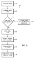
- FIG. 9 is a flowchart of a method of operating an imaging system to acquire image data via a digital detector and to communicate such data from the detector in accordance with one embodiment.
- the articles “a,” “an,” “the,” and “said” are intended to mean that there are one or more of the elements.
- the terms “comprising,” “including,” and “having” are intended to be inclusive and mean that there may be additional elements other than the listed elements.
- exemplary may be used herein in connection to certain examples of aspects or embodiments of the presently disclosed technique, it will be appreciated that these examples are illustrative in nature and that the term “exemplary” is not used herein to denote any preference or requirement with respect to a disclosed aspect or embodiment.
- any use of the terms “top,” “bottom,” “above,” “below,” other positional terms, and variations of these terms is made for convenience, but does not require any particular orientation of the described components.
- FIG. 1 illustrates diagrammatically an imaging system 10 for acquiring and processing discrete pixel image data.
- the imaging system 10 is a digital X-ray system designed both to acquire original image data and to process the image data for display in accordance with the present technique.
- imaging system 10 includes a source of X-ray radiation 12 positioned adjacent to a collimator 14 .
- the collimator 14 permits a stream of radiation 16 to pass into a region in which an object or subject, such as a patient 18 , is positioned.
- a portion of the radiation 20 passes through or around the subject and impacts a digital X-ray detector, represented generally at reference numeral 22 .
- the detector 22 may convert the X-ray photons received on its surface to lower energy photons, and subsequently to electric signals, which are acquired and processed to reconstruct an image of the features within the subject.
- the radiation source 12 is controlled by a power supply/control circuit 24 which supplies both power and control signals for examination sequences.
- the detector 22 is communicatively coupled to a detector controller 26 which commands acquisition of the signals generated in the detector 22 .
- the detector 22 may communicate with the detector controller 26 via any suitable wireless communication standard, although the use of detectors 22 that communicate with the detector controller 26 through a cable or some other mechanical connection are also envisaged.
- the detector controller 26 may also execute various signal processing and filtration functions, such as for initial adjustment of dynamic ranges, interleaving of digital image data, and so forth.
- Both the power supply/control circuit 24 and the detector controller 26 are responsive to signals from a system controller 28 .
- the system controller 28 commands operation of the imaging system to execute examination protocols and to process acquired image data.
- the system controller 28 also includes signal processing circuitry, typically based upon a programmed general purpose or application-specific digital computer; and associated manufactures, such as optical memory devices, magnetic memory devices, or solid-state memory devices, for storing programs and routines executed by a processor of the computer to carry out various functionalities, as well as for storing configuration parameters and image data; interface circuits; and so forth.
- the system controller 28 is linked to at least one output device, such as a display or printer as indicated at reference numeral 30 .
- the output device may include standard or special purpose computer monitors and associated processing circuitry.
- One or more operator workstations 32 may be further linked in the system for outputting system parameters, requesting examinations, viewing images, and so forth.
- displays, printers, workstations, and similar devices supplied within the system may be local to the data acquisition components, or may be remote from these components, such as elsewhere within an institution or hospital, or in an entirely different location, linked to the image acquisition system via one or more configurable networks, such as the Internet, virtual private networks, and so forth.
- FIG. 2 a perspective view of an imaging system 34 is provided in FIG. 2 in accordance with one embodiment.
- the imaging system 34 includes an overhead tube support arm 38 for positioning a radiation source 12 , such as an X-ray tube, with respect to a patient 18 and a detector 22 .
- a radiation source 12 such as an X-ray tube
- the imaging system 34 may also include any or all of the other components described above with respect to FIG. 1 , such as the system controller 28 .
- the imaging system 34 may be used in consort with one or both of a patient table 44 and a wall stand 48 to facilitate image acquisition.
- the table 44 and the wall stand 48 may be configured to receive one or more digital detectors 22 .
- a digital detector 22 may be placed on the upper surface of the table 44
- the patient 18 (more specifically, an anatomy of interest of the patient 18 ) may be positioned on the table 44 between the detector 22 and the radiation source 12 .
- the detector 22 may be positioned in a slot 46 below the upper surface of the table 44 and the patient 18 , or the radiation source 12 and the detector 22 may be positioned horizontally about the patient 18 for cross-table imaging.
- the wall stand 48 may include a receiving structure 50 also adapted to receive the digital detector 22 , and the patient 18 may be positioned adjacent the wall stand 48 to enable image data to be acquired via the digital detector 22 .
- the imaging system 34 may be a stationary system disposed in a fixed X-ray imaging room, such as that generally depicted in, and described above with respect to, FIG. 2 . It will be appreciated, however, that the presently disclosed techniques may also be employed with other imaging systems, including mobile X-ray units and systems, in other embodiments. For instance, in other embodiments, a mobile X-ray unit may be moved to a patient recovery room, an emergency room, a surgical room, or the like to enable imaging of a patient without requiring transport of the patient to a dedicated (i.e., fixed) X-ray imaging room.
- the detector 22 may include a housing 58 that encloses various components of the detector 22 .
- the housing 58 may include a window 60 that exposes a solid-state detector array 62 within the housing 58 .
- the detector array 62 may be configured to receive electromagnetic radiation, such as from the radiation source 12 , and to convert the radiation into electrical signals that may be interpreted by the imaging system 34 to output an image of an object or patient 18 .
- the housing 58 may also include one or more handles 64 that facilitate positioning and transport of the detector 22 by a technician or other user.
- Operating power may be provided to the digital detector 22 via a power connector 66 configured to engage either of a removable battery or a cable (e.g., a tether), as discussed in greater detail below.
- the connector 66 may generally include a receptacle for receiving either the removable battery or the tether and may include electrical contacts to route power from the battery or from an external power source via the tether to the various components of the digital detector 22 .
- the digital detector 22 may communicate with one or more other components of the imaging system 34 , such as the system controller 28 , via a wireless transceiver 68 .
- the wireless transceiver 68 may utilize any suitable wireless communication protocol, such as an ultra wideband (UWB) communication standard, a Bluetooth communication standard, or any 802.11 communication standard. Additionally, the digital detector 22 may also communicate data over a wired connection, such as via a tether coupled to the digital detector 22 by way of the connector 66 , or via another cable coupled elsewhere to the digital detector 22 .
- UWB ultra wideband
- Bluetooth Bluetooth
- 802.11 communication standard 802.11 communication standard.
- the digital detector 22 may also communicate data over a wired connection, such as via a tether coupled to the digital detector 22 by way of the connector 66 , or via another cable coupled elsewhere to the digital detector 22 .
- the digital detector 22 may include a memory device 70 .
- the memory device 70 may store image data acquired via the detector array 62 .
- the memory device 70 may include an optical memory device, a magnetic memory device, or a solid state-memory device.
- the memory device 70 may be a non-volatile memory device, such as a flash memory.
- the memory device 70 may be internally or externally located with respect to the housing 58 and, depending on the embodiment, may or may not be configured to facilitate user-removal of the memory device 70 from the housing 58 .
- the connector 66 , the wireless transceiver 68 , and the memory device 70 may generally be located in one end of the detector 22 as illustrated in FIG. 3 , the present technique is not limited to such positions. Rather, these components may be provided at any suitable location of the detector 22 in full accordance with the present techniques. Additionally, in some embodiments, the housing 58 may include various indicators 72 , such as light-emitting diodes, that communicate detector status, operation, or the like to a user.
- a removable battery 76 may be inserted (as generally indicated by reference numeral 78 ) into a receptacle of the connector 66 , as generally illustrated in FIG. 5 .
- the battery 76 may include a power indicator 80 that provides a user with an indication of the amount of remaining battery power.
- the power indicator 80 includes a visual power indicator, such as one or more LED lights, an LCD display, or the like, that generally communicates information regarding the remaining charge of the removable battery 76 , although the power indicator 80 of other embodiments may also or instead include an auditory power indicator.
- a visual power indicator 80 may include a series of LED lights that generally represent the remaining charge on the battery 76 , or may include a LCD or some other display that outputs the percentage of remaining power left.
- the connector 66 is provided at an edge of the detector 22 such that the battery 76 is received in a manner generally parallel to the plane of the detector (i.e., generally perpendicular to the normal of the detecting surface of the detector 22 ).
- providing the power indicator 80 on a distal end of the battery 76 that remains externally viewable once installed in the connector 66 may allow a user to more easily determine the remaining charge of the battery 76 , even during use of the detector 22 .
- the power indicator 80 is presently depicted as located on one end of the battery 76 , it is noted that the power indicator 80 may also or instead be positioned on the other sides of the battery 76 , and that the connector 66 may be provided at other orientations and locations of the detector 22 .
- the removable battery 76 includes a button 82 or some other mechanism that enables a user to activate or deactivate the power indicator 80 .
- a user may press button 82 to turn on the power indicator 80 and may again press the button 82 , in turn, to deactivate the power indicator 80 .
- the power indicator 80 may, in some embodiments, be automatically deactivated via a timer.
- the power indicator 80 may provide an indication that the remaining power of the battery 76 has fallen to or below a threshold level, such as ten percent or twenty percent power remaining. For example, when the remaining power of the battery 76 is below such a threshold, the power indicator 80 may flash or change color to signal to a user to change the battery 76 . Additionally, in some embodiments, upon depletion of the battery charge below the threshold, the digital detector 22 may communicate with the system controller 28 to cause some other component of the imaging system 34 to communicate the battery status to a user.
- a threshold level such as ten percent or twenty percent power remaining.
- the power indicator 80 may flash or change color to signal to a user to change the battery 76 .
- the digital detector 22 may communicate with the system controller 28 to cause some other component of the imaging system 34 to communicate the battery status to a user.
- a visual indicator may be provided on a display screen of the operator interface 32 or some other component of the imaging system 34 , or some component of the imaging system 34 may output an audio signal, such as one or more beeps, to notify the user of the battery condition.
- the digital detector 22 may be configured to automatically turn itself off following completion of an image acquisition procedure when the remaining power of the battery 76 falls below the aforementioned threshold, or below an additional threshold.
- image data acquired by the digital detector 22 may be stored within the memory device 70 prior to deactivation of the digital detector 22 , and such stored data may be later communicated from the digital detector 22 upon installation of a charged battery 76 or a tether, as generally discussed below.
- the battery 76 and/or the connector 66 may include locking features 84 that facilitate the retention of the battery 76 by the connector 66 .
- any suitable locking features such as one or more sets of mating latches and recesses, may be employed in full accordance with the present techniques.
- the digital detector 22 includes a release mechanism 86 that facilitates unlocking of the battery 76 to the connector 66 to facilitate removal of the battery 76 from the digital detector 22 .
- the imaging system 34 may also include a battery charging station 96 configured to recharge one or more batteries 76 for the digital detector 22 . It is noted that, for embodiments in which the batteries 76 are user-removable from the digital detector 22 , a depleted battery 76 may be removed from the digital detector 22 and replaced with a charged battery 76 . This, in turn, enables continued operation of the detector 22 (with the newly installed, charged, battery 76 ) with minimal downtime (e.g., the time needed to replace a battery), while also enabling the depleted battery 76 to be recharged, such as by the battery charging station 96 , independent of the detector 22 .
- a battery charging station 96 configured to recharge one or more batteries 76 for the digital detector 22 .
- the battery charging station 96 may be attached to the portable X-ray unit 36 or may be provided elsewhere in the imaging system 34 .
- the battery charging station 96 includes several slots 98 configured to receive removable battery 76 .
- each slot 98 may include electrical connections that mate with those of a respective battery 76 to enable recharging of the battery 76 .
- a power indicator 100 may be provided for each slot 98 for generally indicating the level of charge on the associated battery 76 .
- the presently illustrated battery charging station 96 includes slots for recharging up to three batteries 76 , it is noted that other embodiments may allow for charging a different number of batteries. In one embodiment, once a particular battery 76 is fully charged, the battery charging station 96 will automatically turn off the charging current for that particular battery 76 .
- a battery 76 may be removed from the connector 66 of the digital detector 22 and a tether 104 may be coupled in its place, as generally illustrated in FIGS. 7 and 8 in accordance with one embodiment.
- the tether 104 includes a plug 106 that may be inserted into the connector 66 , as generally indicated by reference numeral 108 .
- a cable portion 110 of the tether 104 may provide operating power to the digital detector 22 .
- data acquired by the digital detector 22 may be communicated to other components of the imaging system 34 via the cable 110 .
- the tether 104 may enable wired communication providing higher data transmission rates than that supported via wireless communication, and a user may choose between wired or wireless communication based on desired data transfer rates, ergonomic considerations, and the like.
- the tether 104 may also include locking features 112 that facilitate the retention of the tether 104 by the connector 66 .
- the release mechanism 86 may be used to disengage the tether 104 from the connector 66 in a manner similar to that discussed above with respect to removal of the battery 76 from the connector 66 .
- image data may be acquired by, and communicated from, a digital detector 22 in accordance with a method 116 of one embodiment.
- the method 116 may include exposing the detector 22 to radiation, such as from the radiation source 12 , in a step 118 .
- the method 116 may also include generating image data, in a step 120 , based on the received radiation.
- the digital detector 22 may have a battery 76 coupled to the connector 66 and may be operating wirelessly. In such an instance, communication of the acquired data may be performed wirelessly via the transceiver 68 , as generally discussed above.
- wireless communication may or may not be suitable, desirable, or even available, as generally represented by decision block 122 .
- the image data acquired by the digital detector 22 may be transmitted wirelessly, in a step 124 .
- the tether 104 may be coupled to the detector 22 prior to commencing a new examination or image acquisition process, allowing the acquired data to be communicated from the detector 22 via the tether 104 throughout the examination. In other cases, however, it may be desirable for image acquisition commenced with the digital detector 22 operating in a wireless communication mode to be completed in a wired communication mode (e.g., in the event of the loss of adequate wireless signal or insufficient battery power).
- the image data may be stored in a memory of the detector 22 (e.g., memory device 70 ) in a step 126 prior to removing the battery 76 from the digital detector 22 , in a step 128 . It is noted that, in various embodiments, the image data may be stored in the memory at any suitable time following acquisition, which may include storing the image data prior to, during, or following any attempt to wirelessly communicate the image data. Additionally, the detector 22 may provide an output to indicate to a user that the data has been stored in the memory and is available for subsequent transmission, such as via the tether 104 .
- This output may include a visual output, an auditory output, or both, and may be provided via the power indicator 80 or through some other additional output device of the battery 76 or the detector 22 .
- the tether 104 may be coupled to the digital detector 22 via the connector 66 , in a step 130 , and the image data may be communicated from the memory device via the tether 104 , in a step 132 .
- a memory device of the digital detector may store data acquired by the digital detector, which may enable retention of the data in the event of power loss (e.g., upon removal of a battery) and communication of the data either via a tether or wirelessly at a subsequent time.
Priority Applications (3)
| Application Number | Priority Date | Filing Date | Title |
|---|---|---|---|
| US12/403,551 US7852985B2 (en) | 2009-03-13 | 2009-03-13 | Digital image detector with removable battery |
| JP2010053927A JP5593096B2 (ja) | 2009-03-13 | 2010-03-11 | 着脱式バッテリを有するディジタル画像検出器 |
| FR1051802A FR2943141A1 (fr) | 2009-03-13 | 2010-03-12 | Detecteur numerique d'image a batterie amovible |
Applications Claiming Priority (1)
| Application Number | Priority Date | Filing Date | Title |
|---|---|---|---|
| US12/403,551 US7852985B2 (en) | 2009-03-13 | 2009-03-13 | Digital image detector with removable battery |
Publications (2)
| Publication Number | Publication Date |
|---|---|
| US20100230606A1 US20100230606A1 (en) | 2010-09-16 |
| US7852985B2 true US7852985B2 (en) | 2010-12-14 |
Family
ID=42668949
Family Applications (1)
| Application Number | Title | Priority Date | Filing Date |
|---|---|---|---|
| US12/403,551 Active US7852985B2 (en) | 2009-03-13 | 2009-03-13 | Digital image detector with removable battery |
Country Status (3)
| Country | Link |
|---|---|
| US (1) | US7852985B2 (ja) |
| JP (1) | JP5593096B2 (ja) |
| FR (1) | FR2943141A1 (ja) |
Cited By (9)
| Publication number | Priority date | Publication date | Assignee | Title |
|---|---|---|---|---|
| US20100004790A1 (en) * | 2008-07-01 | 2010-01-07 | Carina Technology, Inc. | Water Heater Demand Side Management System |
| US20110188630A1 (en) * | 2010-01-29 | 2011-08-04 | Fujifilm Corporation | Radiographic image capturing apparatus and radiographic image capturing system |
| US8399847B2 (en) | 2010-11-11 | 2013-03-19 | General Electric Company | Ruggedized enclosure for a radiographic device |
| US8721176B2 (en) | 2011-05-06 | 2014-05-13 | General Electric Company | Rechargeable image detector system and method |
| US20150131782A1 (en) * | 2013-11-08 | 2015-05-14 | Samsung Electronics Co., Ltd. | Medical imaging system and workstation and x-ray detector thereof |
| US9101316B2 (en) | 2011-11-30 | 2015-08-11 | General Electric Company | Portable radiation detector and system |
| US20180116615A1 (en) * | 2015-07-31 | 2018-05-03 | Fujifilm Corporation | Radiation-irradiation device |
| US20180270938A1 (en) * | 2016-08-03 | 2018-09-20 | Samsung Electronics Co., Ltd. | Mobile x-ray apparatus including a battery management system |
| US11357459B2 (en) * | 2017-04-19 | 2022-06-14 | Canon Kabushiki Kaisha | Radiation imaging apparatus configured to receive a power in a non-contact manner, radiation imaging system, radiation imaging method, and computer-readable medium |
Families Citing this family (15)
| Publication number | Priority date | Publication date | Assignee | Title |
|---|---|---|---|---|
| US8941070B2 (en) * | 2008-11-19 | 2015-01-27 | General Electric Company | Portable digital image detector positioning apparatus |
| JP5517855B2 (ja) * | 2010-09-17 | 2014-06-11 | キヤノン株式会社 | X線撮影装置 |
| JP5455857B2 (ja) * | 2010-09-28 | 2014-03-26 | 富士フイルム株式会社 | 放射線画像撮影装置、放射線画像撮影方法、及び放射線画像撮影プログラム |
| JP5265713B2 (ja) | 2011-01-27 | 2013-08-14 | 富士フイルム株式会社 | 電子カセッテ用充電器 |
| JP5718177B2 (ja) * | 2011-06-24 | 2015-05-13 | 富士フイルム株式会社 | 放射線画像撮影システム |
| JP5557816B2 (ja) * | 2011-09-28 | 2014-07-23 | 富士フイルム株式会社 | 放射線画像検出装置 |
| JP6025373B2 (ja) * | 2012-04-13 | 2016-11-16 | キヤノン株式会社 | 放射線画像撮像装置、その制御方法及びプログラム |
| JP6164876B2 (ja) * | 2013-03-06 | 2017-07-19 | キヤノン株式会社 | X線画像撮影システム |
| US20160093924A1 (en) * | 2014-09-29 | 2016-03-31 | Zlick, Inc. | Communication-connected battery with expansion capability |
| US9858784B2 (en) | 2014-09-29 | 2018-01-02 | Roost, Inc. | Battery-powered device having a battery and loud sound detector using passive sensing |
| JP6530926B2 (ja) * | 2015-02-20 | 2019-06-12 | 株式会社イシダ | X線検査装置 |
| USD752226S1 (en) * | 2015-04-15 | 2016-03-22 | R C Imaging, Inc. | Radiographic detector protector |
| USD751715S1 (en) * | 2015-04-15 | 2016-03-15 | RC Imaging, Inc. | Radiographic detector protector |
| USD864394S1 (en) * | 2018-05-17 | 2019-10-22 | General Electric Company | X-ray detector holder |
| JP7399803B2 (ja) | 2020-07-01 | 2023-12-18 | 株式会社東芝 | アルカリ金属の安定化方法及び安定化装置 |
Citations (4)
| Publication number | Priority date | Publication date | Assignee | Title |
|---|---|---|---|---|
| US20040114725A1 (en) * | 2002-11-27 | 2004-06-17 | Osamu Yamamoto | X-ray imaging apparatus |
| US20080240358A1 (en) * | 2007-03-30 | 2008-10-02 | General Electric Company | Wireless X-ray detector power system and method |
| US20090116431A1 (en) | 2007-11-07 | 2009-05-07 | Broadcom Corporation | System and method for optimizing communication between a mobile communications device and a second communications device |
| US7593507B2 (en) | 2007-08-16 | 2009-09-22 | Fujifilm Corporation | Radiation image capturing system and method of setting minimum transmission radio-field intensity in such radiation image capturing system |
Family Cites Families (15)
| Publication number | Priority date | Publication date | Assignee | Title |
|---|---|---|---|---|
| JP3094760B2 (ja) * | 1993-08-25 | 2000-10-03 | 三菱電機株式会社 | 携帯無線機器筺体 |
| JP3494683B2 (ja) * | 1993-11-18 | 2004-02-09 | 富士写真フイルム株式会社 | 放射線検出システム、放射線検出器用カセッテおよび放射線画像撮影方法。 |
| WO1995027221A1 (en) * | 1994-03-31 | 1995-10-12 | Minnesota Mining And Manufacturing Company | Cassette for use in an electronic radiographic imaging system |
| IL121189A0 (en) * | 1997-06-29 | 1997-11-20 | Techtium Ltd | Battery pack assembly |
| JP3577003B2 (ja) * | 2000-06-27 | 2004-10-13 | キヤノン株式会社 | 可搬型放射線画像撮影装置 |
| DE10118745C2 (de) * | 2001-04-17 | 2003-03-06 | Siemens Ag | Röntgeneinrichtung mit transportablem Strahlungsempfänger und mobiler zentraler Steuerungseinrichtung |
| JP4838456B2 (ja) * | 2001-08-27 | 2011-12-14 | キヤノン株式会社 | 放射線画像撮影装置 |
| JP4078096B2 (ja) * | 2002-02-26 | 2008-04-23 | キヤノン株式会社 | 放射線画像撮影装置 |
| JP2003325496A (ja) * | 2002-05-13 | 2003-11-18 | Canon Inc | 放射線撮影装置 |
| FR2853620B1 (fr) * | 2003-04-09 | 2006-05-05 | Max Power | Propulseur retractable par rotation |
| JP2007333381A (ja) * | 2004-09-16 | 2007-12-27 | Konica Minolta Medical & Graphic Inc | 放射線検出器 |
| WO2006030592A1 (ja) * | 2004-09-16 | 2006-03-23 | Konica Minolta Medical & Graphic, Inc. | 放射線検出器及び放射線画像撮影システム |
| JP4682650B2 (ja) * | 2005-03-10 | 2011-05-11 | コニカミノルタエムジー株式会社 | 放射線画像検出器及び放射線画像撮影システム |
| JP2009053661A (ja) * | 2007-07-30 | 2009-03-12 | Fujifilm Corp | 放射線検出カセッテ及び医療システム |
| US7849847B2 (en) * | 2007-09-11 | 2010-12-14 | Asm Assembly Automation Ltd | Drainage apparatus for a singulation system |
-
2009
- 2009-03-13 US US12/403,551 patent/US7852985B2/en active Active
-
2010
- 2010-03-11 JP JP2010053927A patent/JP5593096B2/ja active Active
- 2010-03-12 FR FR1051802A patent/FR2943141A1/fr not_active Withdrawn
Patent Citations (4)
| Publication number | Priority date | Publication date | Assignee | Title |
|---|---|---|---|---|
| US20040114725A1 (en) * | 2002-11-27 | 2004-06-17 | Osamu Yamamoto | X-ray imaging apparatus |
| US20080240358A1 (en) * | 2007-03-30 | 2008-10-02 | General Electric Company | Wireless X-ray detector power system and method |
| US7593507B2 (en) | 2007-08-16 | 2009-09-22 | Fujifilm Corporation | Radiation image capturing system and method of setting minimum transmission radio-field intensity in such radiation image capturing system |
| US20090116431A1 (en) | 2007-11-07 | 2009-05-07 | Broadcom Corporation | System and method for optimizing communication between a mobile communications device and a second communications device |
Non-Patent Citations (2)
| Title |
|---|
| Liu, James Zhengshe et al.; U.S. Appl. No. 12/414,848; filed Mar. 31, 2009; entitled "Wireless Digital Image Detector". |
| Thales Components & Subsystems, "Pixium Portable 3543," Mar. 2008, Velizy Cedex, France. |
Cited By (15)
| Publication number | Priority date | Publication date | Assignee | Title |
|---|---|---|---|---|
| US8204633B2 (en) * | 2008-07-01 | 2012-06-19 | Carina Technology, Inc. | Water heater demand side management system |
| US20100004790A1 (en) * | 2008-07-01 | 2010-01-07 | Carina Technology, Inc. | Water Heater Demand Side Management System |
| US20110188630A1 (en) * | 2010-01-29 | 2011-08-04 | Fujifilm Corporation | Radiographic image capturing apparatus and radiographic image capturing system |
| US8798235B2 (en) * | 2010-01-29 | 2014-08-05 | Fujifilm Corporation | Radiographic image capturing apparatus and radiographic image capturing system |
| US8399847B2 (en) | 2010-11-11 | 2013-03-19 | General Electric Company | Ruggedized enclosure for a radiographic device |
| US8721176B2 (en) | 2011-05-06 | 2014-05-13 | General Electric Company | Rechargeable image detector system and method |
| US9101316B2 (en) | 2011-11-30 | 2015-08-11 | General Electric Company | Portable radiation detector and system |
| US20150131782A1 (en) * | 2013-11-08 | 2015-05-14 | Samsung Electronics Co., Ltd. | Medical imaging system and workstation and x-ray detector thereof |
| US10058297B2 (en) * | 2013-11-08 | 2018-08-28 | Samsung Electronics Co., Ltd. | Medical imaging system and workstation and X-ray detector thereof |
| US11278251B2 (en) | 2013-11-08 | 2022-03-22 | Samsung Electronics Co., Ltd. | Medical imaging system and workstation and X-ray detector thereof |
| US20180116615A1 (en) * | 2015-07-31 | 2018-05-03 | Fujifilm Corporation | Radiation-irradiation device |
| US10856821B2 (en) * | 2015-07-31 | 2020-12-08 | Fujifilm Corporation | Radiation-irradiation device including a cradle that supports an edge portion of a radiation detector |
| US20180270938A1 (en) * | 2016-08-03 | 2018-09-20 | Samsung Electronics Co., Ltd. | Mobile x-ray apparatus including a battery management system |
| US10652988B2 (en) * | 2016-08-03 | 2020-05-12 | Samsung Electronics Co., Ltd. | Mobile x-ray apparatus including a battery management system |
| US11357459B2 (en) * | 2017-04-19 | 2022-06-14 | Canon Kabushiki Kaisha | Radiation imaging apparatus configured to receive a power in a non-contact manner, radiation imaging system, radiation imaging method, and computer-readable medium |
Also Published As
| Publication number | Publication date |
|---|---|
| JP5593096B2 (ja) | 2014-09-17 |
| US20100230606A1 (en) | 2010-09-16 |
| FR2943141A1 (fr) | 2010-09-17 |
| JP2010214108A (ja) | 2010-09-30 |
Similar Documents
| Publication | Publication Date | Title |
|---|---|---|
| US7852985B2 (en) | Digital image detector with removable battery | |
| US8324585B2 (en) | Digital image detector | |
| US8941070B2 (en) | Portable digital image detector positioning apparatus | |
| US8975868B2 (en) | Charging station for portable X-ray detectors | |
| US7696722B2 (en) | Battery powered X-ray detector power system and method | |
| US7873145B2 (en) | Wireless digital image detector | |
| JP5914503B2 (ja) | 放射線撮影システムおよび放射線撮影システムの通信方法、並びに放射線画像検出装置 | |
| US7777192B2 (en) | Cassette system | |
| JP2011521704A (ja) | デジタルエックス線撮影装置 | |
| US7740405B2 (en) | Cassette | |
| EP2380495A1 (en) | Radiographic image detection device and radiographic imaging system | |
| US20090039276A1 (en) | Radiation detecting cassette and radiation image capturing system | |
| US20090250621A1 (en) | Radiation detecting cassette and radiation image capturing system | |
| JP2011072678A (ja) | 放射線画像撮影装置、放射線画像撮影システム、およびプログラム | |
| JP5296431B2 (ja) | 放射線画像撮影システム | |
| JP5763507B2 (ja) | 可搬型放射線画像検出装置及び放射線撮影装置並びに放射線撮影システム | |
| JP2009048171A (ja) | カセッテ装置及び該カセッテ装置に設けられるカセッテ収納袋 | |
| JP2010025707A (ja) | 警告装置及びプログラム | |
| JP2009050686A (ja) | カセッテ及び放射線画像撮影システム | |
| JP5289089B2 (ja) | 放射線画像撮影システム、電源装置、充電装置、および放射線画像撮影方法 | |
| JP2009050691A (ja) | 放射線画像撮影システム | |
| KR20180105453A (ko) | 구강내 센서 및 이를 포함한 x선 촬영 시스템 | |
| JP2011232667A (ja) | 可搬型放射線画像検出装置 | |
| JP2009053670A (ja) | 放射線検出カセッテ及び放射線画像撮影システム | |
| JP2010259680A (ja) | 放射線撮影装置及びカセッテ用コネクタ |
Legal Events
| Date | Code | Title | Description |
|---|---|---|---|
| AS | Assignment |
Owner name: GENERAL ELECTRIC COMPANY, NEW YORK Free format text: ASSIGNMENT OF ASSIGNORS INTEREST;ASSIGNORS:LIU, JAMES ZHENGSHE;LANGLER, DONALD;MCBROOM, GARY V.;REEL/FRAME:022392/0498 Effective date: 20090304 |
|
| FEPP | Fee payment procedure |
Free format text: PAYOR NUMBER ASSIGNED (ORIGINAL EVENT CODE: ASPN); ENTITY STATUS OF PATENT OWNER: LARGE ENTITY |
|
| STCF | Information on status: patent grant |
Free format text: PATENTED CASE |
|
| FPAY | Fee payment |
Year of fee payment: 4 |
|
| MAFP | Maintenance fee payment |
Free format text: PAYMENT OF MAINTENANCE FEE, 8TH YEAR, LARGE ENTITY (ORIGINAL EVENT CODE: M1552) Year of fee payment: 8 |
|
| MAFP | Maintenance fee payment |
Free format text: PAYMENT OF MAINTENANCE FEE, 12TH YEAR, LARGE ENTITY (ORIGINAL EVENT CODE: M1553); ENTITY STATUS OF PATENT OWNER: LARGE ENTITY Year of fee payment: 12 |