US7775336B2 - Friction engagement device - Google Patents
Friction engagement device Download PDFInfo
- Publication number
- US7775336B2 US7775336B2 US11/703,793 US70379307A US7775336B2 US 7775336 B2 US7775336 B2 US 7775336B2 US 70379307 A US70379307 A US 70379307A US 7775336 B2 US7775336 B2 US 7775336B2
- Authority
- US
- United States
- Prior art keywords
- lubricating oil
- annular plates
- spline
- friction
- oil supply
- Prior art date
- Legal status (The legal status is an assumption and is not a legal conclusion. Google has not performed a legal analysis and makes no representation as to the accuracy of the status listed.)
- Expired - Fee Related, expires
Links
Images


Classifications
-
- F—MECHANICAL ENGINEERING; LIGHTING; HEATING; WEAPONS; BLASTING
- F16—ENGINEERING ELEMENTS AND UNITS; GENERAL MEASURES FOR PRODUCING AND MAINTAINING EFFECTIVE FUNCTIONING OF MACHINES OR INSTALLATIONS; THERMAL INSULATION IN GENERAL
- F16D—COUPLINGS FOR TRANSMITTING ROTATION; CLUTCHES; BRAKES
- F16D25/00—Fluid-actuated clutches
- F16D25/12—Details not specific to one of the before-mentioned types
- F16D25/123—Details not specific to one of the before-mentioned types in view of cooling and lubrication
-
- F—MECHANICAL ENGINEERING; LIGHTING; HEATING; WEAPONS; BLASTING
- F16—ENGINEERING ELEMENTS AND UNITS; GENERAL MEASURES FOR PRODUCING AND MAINTAINING EFFECTIVE FUNCTIONING OF MACHINES OR INSTALLATIONS; THERMAL INSULATION IN GENERAL
- F16D—COUPLINGS FOR TRANSMITTING ROTATION; CLUTCHES; BRAKES
- F16D13/00—Friction clutches
- F16D13/58—Details
- F16D13/60—Clutching elements
- F16D13/64—Clutch-plates; Clutch-lamellae
- F16D13/68—Attachments of plates or lamellae to their supports
- F16D13/683—Attachments of plates or lamellae to their supports for clutches with multiple lamellae
-
- F—MECHANICAL ENGINEERING; LIGHTING; HEATING; WEAPONS; BLASTING
- F16—ENGINEERING ELEMENTS AND UNITS; GENERAL MEASURES FOR PRODUCING AND MAINTAINING EFFECTIVE FUNCTIONING OF MACHINES OR INSTALLATIONS; THERMAL INSULATION IN GENERAL
- F16D—COUPLINGS FOR TRANSMITTING ROTATION; CLUTCHES; BRAKES
- F16D13/00—Friction clutches
- F16D13/58—Details
- F16D13/74—Features relating to lubrication
-
- F—MECHANICAL ENGINEERING; LIGHTING; HEATING; WEAPONS; BLASTING
- F16—ENGINEERING ELEMENTS AND UNITS; GENERAL MEASURES FOR PRODUCING AND MAINTAINING EFFECTIVE FUNCTIONING OF MACHINES OR INSTALLATIONS; THERMAL INSULATION IN GENERAL
- F16H—GEARING
- F16H57/00—General details of gearing
- F16H57/04—Features relating to lubrication or cooling or heating
- F16H57/048—Type of gearings to be lubricated, cooled or heated
- F16H57/0482—Gearings with gears having orbital motion
-
- F—MECHANICAL ENGINEERING; LIGHTING; HEATING; WEAPONS; BLASTING
- F16—ENGINEERING ELEMENTS AND UNITS; GENERAL MEASURES FOR PRODUCING AND MAINTAINING EFFECTIVE FUNCTIONING OF MACHINES OR INSTALLATIONS; THERMAL INSULATION IN GENERAL
- F16D—COUPLINGS FOR TRANSMITTING ROTATION; CLUTCHES; BRAKES
- F16D2300/00—Special features for couplings or clutches
- F16D2300/06—Lubrication details not provided for in group F16D13/74
Definitions
- the present invention relates to a friction engagement device.
- a predetermined rotary element of a planetary gear device is connected to an input shaft by a clutch or subjected to rotation restriction by a brake in order to achieve a desired shift speed.
- a friction plate adhered on both the front and rear surface with a plurality of friction materials and a separator plate are pressed together such that relative rotation between a first member and a second member spline-fitted to the friction plate and separator plate, respectively, is restricted.
- a plurality of lubricating oil grooves are provided radially between adjacent friction materials. Lubricating oil is supplied to the plurality of lubricating oil grooves through lubricating oil supply holes drilled in the first member.
- Japanese Patent Application Publication No. JP-A-2000-145819 pages 3 and 4, FIGS. 1, 2, and 3) describes an invention in which a plurality of lubricating oil supply holes 12 drilled into a hub 8 (first member) of a wet type multiplate clutch 20 and a plurality of through oil grooves 11 (lubricating oil grooves) provided radially in both the front and rear surfaces of a friction plate 7 spline-fitted to the hub 8 are caused to face each other to reduce drag torque generated as a result of the viscosity of the lubricating oil used in the wet type multiplate clutch 20.
- the lubricating oil that flows through the through oil grooves 11 flows in the manner illustrated by arrow A in FIG. 3 of Japanese Patent Application Publication No. JP-A-2000-145819, thereby improving the dischargeability of the oil.
- the lubricating oil supply holes 12 in the hub 8 face an opening portion on the inner peripheral edge side of the through oil grooves 11, and therefore the lubricating oil flows more smoothly.
- the viscosity shearing resistance of the oil generated between the friction surfaces of the friction plate 7 and a separator plate 3 is reduced. Using this principle, drag torque is reduced.
- the lubricating oil that flows out of each lubricating oil supply hole 12 concentrates in the opposing through oil groove 11 and flows in an outer peripheral direction, while the lubricating oil that flows out of each through oil groove 11 concentrates locally along a spline 4 a provided on the inner periphery of a drum 5 (second member) to which the separator plate 3 is spline-fitted, and flows axially out from one end of the drum 5.
- the present invention thus provides, among other things, a friction engagement device in which lubricating oil, after cooling the friction materials of first annular plates, is dispersed in a circumferential direction over the outer periphery of second annular plates disposed alternately with the first annular plates so as to flow axially, whereby the generation of oil pressure acting on the second annular plates is suppressed by the axial lubricating oil flow, and drag torque is reduced.
- a friction engagement device includes a rotatable, annular first member formed with a concavo-convex spline on an outer periphery thereof, into which a plurality of lubricating oil supply holes are drilled radially; a second member disposed on an outer peripheral side of, and coaxially with, the first member and formed with a concavo-convex spline on an inner periphery thereof; a plurality of first annular plates having friction materials adhered to front and rear surfaces thereof and a plurality of lubricating oil grooves provided therein so as to penetrate radially, the first annular plates being fitted to the first member by a concavo-convex spline formed on an inner periphery thereof; and a plurality of second annular plates disposed alternately with the first annular plates and fitted to the second member by a concavo-convex spline formed on an outer periphery thereof, the second annular plates
- FIG. 1 is a view showing a part of an automatic transmission having a friction engagement device according to an embodiment of the invention
- FIG. 2 is a view showing a speed diagram of the automatic transmission shown in FIG. 1 ;
- FIG. 3 is a front view showing a part of a hub and a friction plate of a friction engagement device according to a first embodiment
- FIG. 4 is an expanded view of FIG. 3 ;
- FIG. 5 is a front view showing a friction plate in which lubricating oil grooves provided in a front surface are disposed in the center of adjacent lubricating oil grooves provided in a rear surface;
- FIG. 6 is a view showing a case in which the lubricating oil grooves in the front surface of the friction plate shown in FIG. 5 overlap lubricating oil supply holes and the lubricating oil grooves in the rear surface do not overlap the lubricating oil supply hole;
- FIG. 7 is a view showing a case in which none of the lubricating oil grooves in the front and rear surfaces of the friction plate shown in FIG. 5 overlap the lubricating oil supply holes;
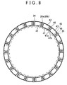
- FIG. 8 is a front view showing a friction plate in which a rear side surface of each friction material adhered to the front surface matches a front side surface of each friction material adhered to the rear surface;
- FIG. 9 is a view showing a case in which the lubricating oil grooves in the front surface of the friction plate shown in FIG. 8 overlap lubricating oil supply holes and the lubricating oil grooves in the rear surface do not overlap the lubricating oil supply holes;
- FIG. 10 is a view showing a case in which none of the lubricating oil grooves in the front and rear surfaces of the friction plate shown in FIG. 8 overlap the lubricating oil supply holes;
- FIG. 11 is a view showing measurement data relating to drag torque generated in accordance with a relative rotation speed between the friction plate and a separator plate.
- FIG. 12 is a view showing a hub in which a spline has been cut into the outer peripheral surface.
- FIG. 1 reference numeral 10 denotes an automatic transmission of a hybrid vehicle.
- a drive shaft 12 connected to an engine via a damper (not shown), is supported rotatably on an axis O.
- a cylindrical input shaft 15 connected to an output shaft 14 of an electric motor 13 , is supported rotatably on the drive shaft 12 via a metal bearing 31 .
- a storage hole 16 having a base is formed in the housing 11 , and a compound planetary gear 17 and first and second brakes B- 1 , B- 2 , which together comprise the automatic transmission 10 , are stored coaxially in the storage hole 16 on an outer peripheral side of the input shaft 15 .
- a first sun gear S 1 of the compound planetary gear 17 is formed at the rear end of the input shaft 15 , and a second sun gear S 2 is supported rotatably on the input shaft 15 in series with the first sun gear S 1 by two metal bearings 18 .
- Common carriers C 1 , C 2 are fixed to an output shaft 19 that is supported rotatably in the housing 11 on the axis O, and the output shaft 19 is coupled to the drive shaft 12 .
- a pinion 22 and a stepped pinion 23 are supported rotatably by respective needle bearings on pinion shafts 20 , 21 that are supported at both ends on the common carriers C 1 , C 2 .
- the pinion 22 meshes with the first sun gear S 1 and common ring gears R 1 , R 2 .
- a small diameter pinion 23 a of the stepped pinion 23 meshes with the pinion 22
- a large diameter pinion 23 b meshes with the second sun gear S 2
- the common ring gears R 1 , R 2 are fitted to the outer periphery of an annular circular plate body 26 , which is supported on the output shaft 19 by a metal bearing 24 and a thrust bearing 25 so as to be capable of relative relation, through a stepped hole, and axial movement thereof is restricted by a snap ring 27 .
- the first and second brakes B- 1 , B- 2 restrict rotation of the common ring gears R 1 , R 2 and the second sun gear S 2 by pressing a plurality of friction plates 28 and a plurality of separator plates 29 , disposed alternately, against each other.
- the plurality of friction plates 28 of the second brake B- 2 are spline-engaged with the outer peripheral surface of the common ring gears R 1 , R 2
- the plurality of separator plates 29 are spline-engaged with a spline 33 formed in the storage hole 16 of the housing 11 .
- the second brake B- 2 is engaged and disengaged by a piston 40 of a hydraulic servo, not shown in the drawing.
- the plurality of friction plates 28 of the first brake B- 1 are spline-fitted to the outer peripheral surface of a rotatable hub 32 on the outside of the large diameter pinion 23 b of the stepped pinion 23 about the axis O.
- the plurality of separator plates 29 are spline-fitted to a spline 30 formed in the storage hole 16 of the housing 11 .
- the hub 32 is bent at one end so as to extend radially, and is joined integrally to a flange portion 39 formed on the second sun gear S 2 .
- the flange portion 39 is movement-restricted in the direction of the axis O by thrust bearings 34 interposed between the two end surfaces of the flange portion 39 and the bottom surface of the storage hole 16 , and between the two end surfaces of the flange portion 39 and the front end surface of the common carriers C 1 , C 2 , respectively.
- a hydraulic servo 35 of the first brake B- 1 is constituted by a cylinder 36 formed in the bottom portion of the storage hole 16 in the housing 11 , a piston 37 disposed slidably in the cylinder 36 , and a compression spring 38 for biasing the piston 37 in a direction for disengaging the friction plates 28 and separator plates 29 .
- the output shaft 14 of the electric motor 13 is connected to the drive shaft 12 at a varied speed by selectively engaging and disengaging the first and second brakes B- 1 , B- 2 .
- the speed ratio of the various elements in the compound planetary gear 17 varies as shown in the speed diagram of FIG. 2 .
- the various elements of the compound planetary gear 17 including the sun gears S 1 , S 2 , the common carriers C 1 , C 2 , and the common ring gears R 1 , R 2 , are disposed at intervals in the abscissa direction corresponding to the gear ratio, and the speed ratio is taken in accordance with each element in the abscissa direction.
- the carriers C 1 and C 2 and the ring gears R 1 and R 2 of a single pinion planetary gear and a double pinion planetary gear are shared, and therefore, the speed ratio of the common carriers C 1 , C 2 and the common ring gears R 1 , R 2 are expressed on single vertical lines denoted as C 1 , C 2 , and R 1 , R 2 , respectively.
- B- 1 , B- 2 are indicated at points where the first and second brakes B- 1 , B- 2 are selectively engaged.
- the output shaft 14 of the electric motor rotates freely.
- the output shaft 14 is connected to the drive shaft 12 at a low speed ratio greater than 1
- the output shaft 14 is connected to the drive shaft 12 at a high speed ratio greater than the low speed ratio.
- a lubricating oil path 41 for supplying lubricating oil to each portion is drilled into the drive shaft 12 , and from the lubricating oil path 41 , small diameter lubricating oil paths 41 a are drilled radially so as to open onto the outer peripheral surface of the drive shaft 12 .
- the lubricating oil that is supplied through the lubricating oil path 41 flows to the outer periphery of the drive shaft 12 through the lubricating oil paths 41 a , passes through a lubricating oil path 48 drilled radially into the input shaft 15 , and flows into the interior of the compound planetary gear 17 . Note that a part of the lubricating oil that is supplied through the lubricating oil paths 41 a , 48 lubricates the metal bearings 18 , 24 , 31 and the thrust bearings 25 , 34 .
- the lubricating oil After flowing into the interior of the compound planetary gear 17 , the lubricating oil lubricates the meshing parts of each gear, and also lubricates the needle bearings for supporting the pinion 22 and stepped pinions 23 on the pinion shafts 20 , 21 .
- the lubricating oil flows out through a plurality of lubricating oil supply holes 42 a , 42 b drilled radially into the hub 32 , and then flows from the inner periphery of each friction plate 28 of the first brake B- 1 toward the outer periphery, thereby cooling friction materials 43 adhered to both the front and rear surfaces of the friction plates 28 .
- the lubricating oil flows in one direction of the axis O along the spline 30 formed in the storage hole 16 of the housing 11 , and is then collected in an oil pan 45 fixed to the lower surface of the automatic transmission 10 .
- the lubricating oil is prevented from flowing forward by a bottom surface 16 a serving as one end of the storage hole 16 adjacent to the first brake B- 1 , and therefore, after cooling the friction materials 43 and flowing to the outer periphery of the friction plates 28 , the lubricating oil flows axially toward an opening at the rear end of the storage hole 16 , which is provided at the rear end of the storage hole 16 for permitting the lubricating oil to flow rearward.
- a lower side peripheral wall 16 b of the storage hole 16 serves as a partition wall between the storage hole 16 and an oil pressure control device 44 for supplying and discharging working oil to and from the hydraulic servo 35 of the first brake B- 1 and so on.
- a large number of oil paths are provided in the lower side peripheral wall 16 b , and therefore, a discharge hole for discharging the lubricating oil to the oil pan 45 after cooling the friction materials 43 and flowing to the outer periphery of the friction plates 28 cannot be drilled into the lower side peripheral wall 16 b .
- all of the lubricating oil that flows to the outer periphery of the friction plates 28 flows in one direction of the axis O along the spline 30 formed in the storage hole 16 , flows out through the opening in the rear end of the storage hole 16 , and is collected in the oil pan 45 therebeneath.
- front and rear surfaces 28 a , 28 b of each friction plate 28 are adhered with the friction materials 43 and provided with a plurality of lubricating oil grooves 46 that penetrate the friction plate 28 radially.
- the plurality of friction materials 43 are adhered to the front and rear surfaces 28 a , 28 b of each friction plate 28 at equal intervals in a circumferential direction, and the lubricating oil grooves 46 are formed between adjacent friction materials 43 so as to penetrate the friction plate 28 radially.
- the lubricating oil that flows out through each lubricating oil supply hole 42 a , 42 b gathers in the opposing lubricating oil groove 46 and flows in an outer peripheral direction, while the lubricating oil that flows out of each lubricating oil groove 46 gathers locally and flows axially along the splines 30 provided on the inner periphery of the storage hole 16 , and is then collected through the rear end opening of the storage hole 16 .
- the plurality of lubricating oil supply holes 42 a , 42 b are drilled radially into the hub 32 , which serves as an example of a first member supported rotatably on the housing 11 , and the plurality of lubricating oil grooves 46 are provided in phase in the circumferential direction in the front and rear surfaces 28 a , 28 b of the friction plate 28 , which serves as an example of a first annular plate.
- the storage hole 16 of the housing 11 which serves as an example of a second member, is disposed on the outer peripheral side of, and on the same O axis as, the hub 32 , and the storage hole 16 stores the plurality of friction plates 28 and the plurality of separator plates 29 disposed alternately with the friction plates 28 .
- the separator plate 29 which serves as an example of a second annular plate, is spline-fitted to the splines 30 formed in the storage hole 16 so as to be capable of contacting the friction materials 43 adhered to the friction plate 28 .
- the hub 32 is formed by pressing a cylinder made of iron plate into a wave form such that a spline 47 is formed on the outer peripheral surface thereof in the direction of the O axis, and the plurality of friction plates 28 are spline-fitted to the spline 47 .
- the plurality of friction materials 43 are adhered in phase to the front and rear surfaces 28 a , 28 b of each friction plate 28 such that when each friction plate 28 is spline-fitted to the hub 32 , an inner surface 43 a of each friction material 43 faces two ridge portions 47 a of the spline 47 , and each of the lubricating oil grooves 46 formed between side faces 43 b of adjacent friction materials 43 faces every second trough portion 47 b of the spline 47 . As shown in FIG. 4 , lubricating oil supply holes 42 a , 42 b are drilled into the ridge portion 47 a of the spline 47 of the hub 32 radially and in staggered form.
- one lubricating oil supply hole 42 a is drilled into one of adjacent ridge portions 47 a of the spline 47 from an axial central part of the hub 32 toward one end, while another lubricating oil supply hole 42 b is drilled into the other ridge portion 47 a from the axial central part of the hub 32 toward the other end.
- the front and rear surfaces 28 a , 28 b of the friction plate 28 are identical, but are differentiated as the front surface 28 a and the rear surface 28 b in the drawings for ease of description.
- the lubricating oil having flowed out through the lubricating oil supply holes 42 a , 42 b , is dispersed in the circumferential direction and flows from the inner periphery to the outer periphery of each friction plate 28 , rather than gathering in the lubricating oil grooves 46 and flowing in the outer peripheral direction. Then, after cooling the friction materials 43 and flowing to the outer periphery of the friction plate 28 , the lubricating oil is dispersed in the circumferential direction so as to flow axially along the splines 30 formed in the storage hole 16 .
- the plurality of lubricating oil grooves 46 are provided in the front and rear surfaces 28 a , 28 b of each friction plate 28 in phase in the circumferential direction, and therefore the friction materials 43 can be adhered to the friction plates 28 easily.
- a second embodiment in which the plurality of friction materials 43 are adhered to the front and rear surfaces 28 a , 28 b of each friction plate at an offset phase in the circumferential direction to ensure that the lubricating oil grooves 46 provided on the front surface 28 a of each friction plate 28 and the lubricating oil grooves 46 provided on the rear surface 28 b of each friction plate 28 do not overlap in groove width in the circumferential direction, will be described.
- the lubricating oil supply holes 42 a , 42 b are drilled into the ridge portions 47 a of the spline 47 of the hub 32 radially and in staggered form.
- the phase offset reaches a maximum when the plurality of friction materials 43 are adhered to the front and rear surfaces 28 a , 28 b of the friction plate 28 such that the lubricating oil grooves 46 formed between adjacent friction materials 43 on the front surface 28 a are positioned in the center of each friction material 43 on the rear surface 28 b.
- the circumferential direction phase offset between the lubricating oil grooves 46 on the front surface 28 a and the lubricating oil grooves 46 on the rear surface 28 b is at a maximum.
- the plurality of friction materials 43 are adhered to the front and rear surfaces 28 a , 28 b of each friction plate 28 by determining the circumferential direction phase thereof relative to the friction plates 28 that are spline-fitted to the hub 32 such that when each friction plate 28 is spline-fitted to the hub 32 , none of the plurality of lubricating oil grooves 46 provided on the front surface 28 a of each friction plate 28 overlap the lubricating oil supply holes 42 a , 42 b in the circumferential direction, and all of the plurality of lubricating oil grooves 46 provided on the rear surface 28 b overlap the lubricating oil supply holes 42 a , 42 b in the circumferential direction.
- the circumferential direction phase offset between the lubricating oil grooves 46 on the front surface 28 a and the lubricating oil grooves 46 on the rear surface 28 b is at a maximum.
- the plurality of friction materials 43 are adhered to the front and rear surfaces 28 a , 28 b of each friction plate 28 by determining the circumferential direction phase thereof relative to the friction plates 28 that are spline-fitted to the hub 32 such that when each friction plate 28 is spline-fitted to the hub 32 , none of the plurality of lubricating oil grooves 46 provided on the front and rear surfaces 28 a , 28 b of each friction plate 28 overlap the lubricating oil supply holes 42 a , 42 b in the circumferential direction.
- the lubricating oil grooves 46 provided on the front surface 28 a of each friction plate 28 are disposed in a central portion between adjacent lubricating oil grooves 46 provided on the rear surface 28 b , and none of the lubricating oil grooves 46 on the front surface 28 a overlap the lubricating oil grooves 46 on the rear surface 28 b in groove width in the circumferential direction.
- the lubricating oil grooves 46 provided on at least one of the front and rear surfaces 28 a , 28 b of all of the friction plates 28 do not overlap the lubricating oil supply holes 42 a , 42 b in the circumferential direction, and therefore the lubricating oil that flows out of the lubricating oil supply holes 42 a , 42 b is dispersed in the circumferential direction in a well-balanced fashion and flows from the inner periphery to the outer periphery of the friction plate 28 , rather than gathering in the lubricating oil grooves 46 and flowing in the outer peripheral direction.
- the lubricating oil After cooling the friction materials 43 and flowing to the outer periphery of the friction plate 28 , the lubricating oil is dispersed in the circumferential direction and flows axially along the splines 30 formed in the storage hole 16 , and therefore the force generated by the axial lubricating oil flow, which acts in a direction for causing the separator plate 29 to contact the friction materials 43 of the friction plate 28 , is suppressed, and drag torque is reduced as shown by measurement data 52 , 53 in FIG. 11 .
- drag torque is reduced by a substantially identical degree, as is evident from the measurement data 52 , 53 shown in FIG. 11 .
- the lubricating oil grooves 46 provided on at least one of the front and rear surfaces 28 a , 28 b do not overlap the lubricating oil supply holes 42 a , 42 b in the circumferential direction
- drag torque is reduced, regardless of the extent to which the lubricating oil grooves 46 provided on the other surface side overlap the lubricating oil supply holes 42 a , 42 b in the circumferential direction.
- the circumferential direction phase offset between the lubricating oil grooves 46 on the front surface 28 a and the lubricating oil grooves 46 on the rear surface 28 b is at a minimum when one side surface of the lubricating oil grooves 46 on the front surface 28 a matches the other surface side of the lubricating oil grooves 46 on the rear surface 28 b .
- the circumferential direction phase offset is at a minimum when the plurality of friction materials 43 are adhered to the front and rear surfaces 28 a , 28 b of the friction plates 28 by matching the rear side surface of each friction material 43 on the front surface 28 a to the front side surface of each friction material 43 on the rear surface 28 b such that the lubricating oil grooves 46 formed between adjacent friction materials 43 on the front surface 28 a overlap the friction materials 43 on the rear surface 28 b.
- the circumferential direction phase offset between the lubricating oil grooves 46 on the front surface 28 a and the lubricating oil grooves 46 on the rear surface 28 b is at a minimum.
- the plurality of friction materials 43 are adhered to the front and rear surfaces 28 a , 28 b of each friction plate 28 by determining the circumferential direction phase thereof relative to the friction plates 28 that are spline-fitted to the hub 32 such that when each friction plate 28 is spline-fitted to the hub 32 , none of the plurality of lubricating oil grooves 46 provided on the front surface 28 a of each friction plate 28 overlap the lubricating oil supply holes 42 a , 42 b in the circumferential direction, and all of the plurality of lubricating oil grooves 46 provided on the rear surface 28 b overlap the lubricating oil supply holes 42 a , 42 b in the circumferential direction.
- the circumferential direction phase offset between the lubricating oil grooves 46 on the front surface 28 a and the lubricating oil grooves 46 on the rear surface 28 b is at a minimum.
- the plurality of friction materials 43 are adhered to the front and rear surfaces 28 a , 28 b of each friction plate 28 by determining the circumferential direction phase thereof relative to the friction plates 28 that are spline-fitted to the hub 32 such that when each friction plate 28 is spline-fitted to the hub 32 , none of the plurality of lubricating oil grooves 46 provided on the front and rear surfaces 28 a , 28 b of each friction plate 28 overlap the lubricating oil supply holes 42 a , 42 b in the circumferential direction.
- the lubricating oil grooves 46 provided on at least one of the front and rear surfaces 28 a , 28 b of all of the friction plates 28 do not overlap the lubricating oil supply holes 42 a , 42 b in the circumferential direction, and therefore the lubricating oil that flows out of the lubricating oil supply holes 42 a , 42 b is dispersed in the circumferential direction and flows from the inner periphery to the outer periphery of the friction plate 28 , rather than gathering in the lubricating oil grooves 46 and flowing in the outer peripheral direction.
- the lubricating oil After cooling the friction materials 43 and flowing to the outer periphery of the friction plate 28 , the lubricating oil is dispersed in the circumferential direction and flows axially along the splines 30 formed in the storage hole 16 , and therefore the force generated by the axial lubricating oil flow, which acts in a direction for causing the separator plate 29 to contact the friction materials 43 of the friction plate 28 , is suppressed, and drag torque is reduced as shown by measurement data 54 , 55 in FIG. 11 .
- drag torque is reduced by a substantially identical degree, as is evident from the measurement data 54 , 55 shown in FIG. 11 .
- the lubricating oil grooves 46 provided on at least one of the front and rear surfaces 28 a , 28 b do not overlap the lubricating oil supply holes 42 a , 42 b in the circumferential direction
- drag torque is reduced, regardless of the extent to which the lubricating oil grooves 46 provided on the other surface side overlap the lubricating oil supply holes 42 a , 42 b in the circumferential direction.
- a structure in which the lubricating oil grooves 46 provided on at least one of the front and rear surfaces 28 a , 28 b of each friction plate 28 do not overlap the lubricating oil supply holes 42 a , 42 b in the circumferential direction when each friction plate 28 is spline-fitted to the hub 32 is sufficient, and therefore the plurality of friction materials 43 need simply be disposed such that each of the lubricating oil grooves 46 provided on the front surface 28 a of each friction plate 28 do not overlap each of the lubricating oil grooves 46 provided on the rear surface 28 b in groove width in the circumferential direction. Accordingly, the plurality of lubricating oil grooves 46 need not be phase-aligned with the lubricating oil supply holes in the circumferential direction, and therefore the plurality of friction materials 43 can be adhered to the friction plates 28 easily.
- the hub 32 serves as an example of a rotatable, annular first member formed with a concavo-convex form spline on the outer periphery thereof, and into which the plurality of lubricating oil supply holes 42 are drilled radially.
- the housing 11 serves as an example of a second member disposed on the outer peripheral side of, and coaxially with, the first member and formed with a concavo-convex spline on the inner periphery thereof.
- the friction plates 28 serve as an example of a plurality of first annular plates having the friction materials 43 adhered to the front and rear surfaces thereof and the plurality of lubricating oil grooves 46 provided therein so as to penetrate radially, and are fitted to the first member by a concavo-convex spline formed on the inner periphery thereof.
- the separator plates 29 serve as an example of a plurality of second annular plates disposed alternately with the first annular plates and fitted to the second member by a concavo-convex spline formed on the outer periphery thereof, the front surfaces of the separator plates 29 being capable of coming into contact with and separating from the friction materials 43 .
- the lubricating oil supply holes 42 are drilled into the ridge portion 47 a or trough portion 47 b of the hub 32 , and of the splines to which each lubricating oil supply hole 42 corresponds, or in other words each ridge portion 47 a or trough portion 47 b into which each lubricating oil supply hole 42 is drilled, the lubricating oil grooves 46 provided in the plurality of friction plates 28 do not overlap the splines on at least one of the front and rear surfaces of the friction plates 28 , or in other words each ridge portion 47 a or trough portion 47 b into which each lubricating oil supply hole 42 is drilled.
- the spline 47 of the hub 32 is formed by pressing a cylindrical body made of iron plate into a wave form, but the spline 47 may be formed by cutting the outer peripheral surface of the cylindrical body, as shown in FIG. 12 . In this case, the lubricating oil supply holes 42 are drilled into the thin trough portions 47 b of the spline 47 .
- the lubricating oil supply holes 42 a , 42 b are drilled into the ridge portions 47 a of the spline 47 of the hub 32 in staggered form.
- lubricating oil supply holes 42 a , 42 b extending from one end to the other end of the hub 32 may be drilled into each of the ridge portions 47 a or trough portions 47 b of the spline 47 , or one lubricating oil supply hole 42 a , 42 b may be drilled into each of a plurality of the ridge portions 47 a or trough portions 47 b .
- the lubricating oil supply holes 42 , 42 a , 42 b may also be drilled into the tooth surface of the spline 47 .
- the number of pairs 42 a , 42 b of the lubricating oil supply holes 42 a , 42 b is identical to the number of lubricating oil grooves 46 provided on either surface of the front and rear surfaces 28 a , 28 b of the friction plate 28 , but one may be an integral multiple of the other.
- the friction engagement device according to the embodiment described above is a brake, but the friction engagement device may be a clutch.
- each of the lubricating oil grooves 46 is provided in the opposing side faces 43 b of adjacent friction materials 43 adhered to the friction plate 28 .
- friction materials 43 having a lubricating oil groove 46 engraved in the front surface thereof may be adhered to the friction plate 28 such that the lubricating oil grooves 46 are provided in the front and rear surfaces 28 a , 28 b of the friction plate 28 so as to penetrate radially.
- the friction engagement device is suitable for use in an automatic transmission which changes the speed of rotation input from an engine via a torque converter among a plurality of shift speeds, and outputs the rotation to a drive wheel of a vehicle.
- a friction engagement device is structured such that lubricating oil supply holes are drilled into a first member that is fitted to a plurality of first annular plates by a spline.
- Lubricating oil grooves provided in the plurality of first annular plates do not overlap splines on at least one of the front and rear surfaces of the first annular plates, from among splines to which each lubricating oil supply hole corresponds, and therefore lubricating oil flowing out of the lubricating oil supply holes is dispersed in a circumferential direction and flows from the inner periphery to the outer periphery of the first annular plates, rather than gathering in each lubricating oil groove and flowing in an outer peripheral direction.
- the lubricating oil is dispersed in the circumferential direction and flows axially along a spline formed on a second member, and therefore a force generated by the axial lubricating oil flow, which acts in a direction for causing the second annular plates to contact the friction materials on the first annular plates, is suppressed, leading to a reduction in drag torque.
- a friction engagement device exhibits similar effects to the friction engagement device according to the first aspect, and is structured such that the plurality of lubricating oil grooves are provided in both the front and rear surfaces of each of the first annular plates in phase in a circumferential direction, whereby the friction materials can be adhered to the first annular plates easily.
- the first annular plates when each of the first annular plates is fitted to the first member by the spline, none of the plurality of lubricating oil grooves overlap each of the splines to which each of the lubricating oil supply holes corresponds in the circumferential direction, and therefore the first annular plates can be attached to the first member easily by being spline-fitted to the first member, without the need for phase alignment in the rotary direction.
- a friction engagement device is structured such that none of the lubricating oil grooves provided in the front surface of each of the first annular plates overlap the lubricating oil grooves provided in the rear surface in groove width in the circumferential direction. Therefore, when each of the first annular plates is spline-fitted to the first member, the plurality of lubricating oil grooves provided on at least one of the front and rear surfaces of the plurality of first annular plates do not overlap the splines to which each of the lubricating oil grooves corresponds in the circumferential direction. As a result, drag torque can be reduced in a similar fashion to the friction engagement device according to the first aspect.
- the plurality of lubricating oil grooves can be provided in the first annular plates easily without the need for phase alignment in the circumferential direction relative to the lubricating oil supply holes.
- a friction engagement device is structured such that the lubricating oil grooves provided in the front surface of each of the first annular plates are disposed in a central portion between adjacent lubricating oil grooves of the plurality of lubricating oil grooves provided in the rear surface, and do not overlap the lubricating oil grooves provided in the rear surface in groove width in the circumferential direction.
- the lubricating oil that flows out of the lubricating oil supply holes is dispersed in a well-balanced fashion in the circumferential direction and flows from the inner periphery to the outer periphery of the first annular plates, thereby achieving similar effects to the friction engagement device according to the first aspect.
- a friction engagement device is structured such that the lubricating oil supply holes are drilled between adjacent lubricating oil grooves in the first annular plates from a central part of the first member toward one end and another end by varying the phase thereof in the circumferential direction.
- lubricating oil flows out evenly from the lubricating oil supply holes drilled in varying phases, and is dispersed so as to flow in the circumferential direction from the inner periphery to the outer periphery of the first annular plates disposed at one end side and the other end side of the first member, thereby achieving similar effects to the friction engagement device according to the first aspect.
- a friction engagement device is structured such that the lubricating oil supply holes are provided along a ridge portion or a trough portion of the spline formed in the first member, and therefore the lubricating oil supply holes can be formed easily. Moreover, the lubricating oil grooves provided in the first annular plates that are spline-fitted to the first member can be phase-aligned to the spline easily if necessary.
- a friction engagement device is structured such that the number of lubricating oil supply holes drilled into the first member and the number of lubricating oil grooves provided in either one of the front and rear surfaces of the first annular plates are set such that one is an integral multiple of the other. Therefore, the first annular plates can be attached to the first member easily through spline fitting, without the need for phase alignment in the rotary direction.
- a friction engagement device is structured such that a side wall for preventing the lubricating oil from flowing is provided in one axial end of a storage hole for storing the plurality of first annular plates and the plurality of second annular plates, and an opening allowing the lubricating oil to flow is provided in the other axial end. Therefore, after cooling the friction materials and flowing to the outer periphery of the first annular plates, the lubricating oil flows axially toward the opening in the storage hole along a spline formed in the storage hole to enable spline fitting to the second annular plates.
- the lubricating oil is dispersed in the circumferential direction, the force generated by the axial lubricating oil flow, which acts in a direction for causing the second annular plates to contact the friction materials on the first annular plates, is suppressed, leading to a reduction in drag torque.
Applications Claiming Priority (2)
| Application Number | Priority Date | Filing Date | Title |
|---|---|---|---|
| JP2006049360A JP4588651B2 (ja) | 2006-02-24 | 2006-02-24 | 摩擦係合装置 |
| JP2006-049360 | 2006-02-24 |
Publications (2)
| Publication Number | Publication Date |
|---|---|
| US20070199789A1 US20070199789A1 (en) | 2007-08-30 |
| US7775336B2 true US7775336B2 (en) | 2010-08-17 |
Family
ID=38437136
Family Applications (1)
| Application Number | Title | Priority Date | Filing Date |
|---|---|---|---|
| US11/703,793 Expired - Fee Related US7775336B2 (en) | 2006-02-24 | 2007-02-08 | Friction engagement device |
Country Status (5)
| Country | Link |
|---|---|
| US (1) | US7775336B2 (ja) |
| EP (1) | EP1950443B1 (ja) |
| JP (1) | JP4588651B2 (ja) |
| CN (1) | CN101346554B (ja) |
| WO (1) | WO2007097081A1 (ja) |
Families Citing this family (11)
| Publication number | Priority date | Publication date | Assignee | Title |
|---|---|---|---|---|
| US20080268997A1 (en) * | 2007-04-24 | 2008-10-30 | Gooden James T | Lubrication path in a planetary gear unit for a transmission |
| AT507251B1 (de) | 2008-09-05 | 2018-03-15 | Miba Frictec Gmbh | Reiblamelle |
| DE102009026709A1 (de) * | 2009-06-04 | 2010-12-09 | Zf Friedrichshafen Ag | Anordnung mit zumindest einem beidseitig hydraulisch betätigbaren Schaltelement |
| WO2010146649A1 (ja) * | 2009-06-15 | 2010-12-23 | トヨタ自動車株式会社 | 制動装置 |
| JP5382030B2 (ja) * | 2011-02-23 | 2014-01-08 | アイシン・エィ・ダブリュ株式会社 | 自動変速装置の摩擦板潤滑装置 |
| US9279492B2 (en) * | 2014-03-18 | 2016-03-08 | Schaeffler Technologies AG & Co. KG | Orientation-free planetary pin for lubrication of planetary bearings |
| JP6289239B2 (ja) * | 2014-04-17 | 2018-03-07 | ジヤトコ株式会社 | 車両用自動変速機の摩擦締結要素における潤滑構造 |
| JP6332472B2 (ja) * | 2014-12-26 | 2018-05-30 | アイシン・エィ・ダブリュ株式会社 | クラッチおよびそれを備えた変速装置 |
| JP6513112B2 (ja) * | 2017-02-23 | 2019-05-15 | 本田技研工業株式会社 | 動力伝達装置及び動力伝達装置の潤滑構造 |
| JP6958446B2 (ja) * | 2018-03-15 | 2021-11-02 | マツダ株式会社 | 自動変速機 |
| JP7070346B2 (ja) * | 2018-11-06 | 2022-05-18 | トヨタ自動車株式会社 | 自動変速機 |
Citations (11)
| Publication number | Priority date | Publication date | Assignee | Title |
|---|---|---|---|---|
| JPS61129930A (ja) | 1984-11-19 | 1986-06-17 | ゼネラル インスツルメント コーポレーシヨン | 直接放送衛星システム |
| JPS61175326A (ja) | 1985-01-31 | 1986-08-07 | Kawasaki Heavy Ind Ltd | 湿式多板多段クラツチ |
| EP0267027A2 (en) * | 1986-11-04 | 1988-05-11 | Daikin-R/M Co. Ltd. | Segment-type friction plate |
| JPH0587341A (ja) | 1991-09-27 | 1993-04-06 | Sharp Corp | 電子レンジ |
| US5964329A (en) * | 1996-05-29 | 1999-10-12 | Exedy Corporation | Torque converter having a lockup clutch |
| JP2000145819A (ja) | 1998-11-06 | 2000-05-26 | Nsk Warner Kk | 湿式多板クラッチ |
| US6283265B1 (en) * | 1999-11-24 | 2001-09-04 | Nsk-Warner K.K. | Wet type multiplate clutch |
| JP2004019945A (ja) | 2002-06-15 | 2004-01-22 | Borgwarner Inc | マルチプレートクラッチ用のプレート |
| US6702088B2 (en) * | 2001-05-15 | 2004-03-09 | Honda Giken Kogyo Kabushiki Kaisha | Wet friction plate |
| US20060049017A1 (en) * | 2004-09-06 | 2006-03-09 | Jatco Ltd | Automatic transmission |
| US20070017769A1 (en) * | 2005-07-22 | 2007-01-25 | Gregory Mordukhovich | Wet clutch friction plate and method |
Family Cites Families (6)
| Publication number | Priority date | Publication date | Assignee | Title |
|---|---|---|---|---|
| JP2580706Y2 (ja) * | 1986-11-04 | 1998-09-17 | 株式会社ダイナックス | 湿式摩擦板 |
| CN2389252Y (zh) * | 1999-09-28 | 2000-07-26 | 重庆市江北区利峰工业制造有限公司 | 摩托车湿式离合器 |
| JP4297308B2 (ja) | 2000-04-13 | 2009-07-15 | アイシン化工株式会社 | 湿式摩擦部材 |
| CN2592948Y (zh) * | 2002-06-19 | 2003-12-17 | 重庆齿轮箱有限责任公司 | 片式液压摩擦离合器 |
| JP2004245332A (ja) | 2003-02-14 | 2004-09-02 | Dainatsukusu:Kk | 湿式摩擦係合装置の潤滑・冷却構造 |
| CN2617993Y (zh) * | 2003-03-15 | 2004-05-26 | 胡济荣 | 全润滑多片湿式离合器 |
-
2006
- 2006-02-24 JP JP2006049360A patent/JP4588651B2/ja not_active Expired - Fee Related
- 2006-11-24 CN CN2006800485769A patent/CN101346554B/zh not_active Expired - Fee Related
- 2006-11-24 WO PCT/JP2006/323485 patent/WO2007097081A1/ja active Application Filing
- 2006-11-24 EP EP06833289A patent/EP1950443B1/en not_active Expired - Fee Related
-
2007
- 2007-02-08 US US11/703,793 patent/US7775336B2/en not_active Expired - Fee Related
Patent Citations (12)
| Publication number | Priority date | Publication date | Assignee | Title |
|---|---|---|---|---|
| JPS61129930A (ja) | 1984-11-19 | 1986-06-17 | ゼネラル インスツルメント コーポレーシヨン | 直接放送衛星システム |
| JPS61175326A (ja) | 1985-01-31 | 1986-08-07 | Kawasaki Heavy Ind Ltd | 湿式多板多段クラツチ |
| EP0267027A2 (en) * | 1986-11-04 | 1988-05-11 | Daikin-R/M Co. Ltd. | Segment-type friction plate |
| JPH0587341A (ja) | 1991-09-27 | 1993-04-06 | Sharp Corp | 電子レンジ |
| US5964329A (en) * | 1996-05-29 | 1999-10-12 | Exedy Corporation | Torque converter having a lockup clutch |
| JP2000145819A (ja) | 1998-11-06 | 2000-05-26 | Nsk Warner Kk | 湿式多板クラッチ |
| US6283265B1 (en) * | 1999-11-24 | 2001-09-04 | Nsk-Warner K.K. | Wet type multiplate clutch |
| US6702088B2 (en) * | 2001-05-15 | 2004-03-09 | Honda Giken Kogyo Kabushiki Kaisha | Wet friction plate |
| JP2004019945A (ja) | 2002-06-15 | 2004-01-22 | Borgwarner Inc | マルチプレートクラッチ用のプレート |
| US7073650B2 (en) | 2002-06-15 | 2006-07-11 | Borgwarner Inc. | Friction plate groove pattern |
| US20060049017A1 (en) * | 2004-09-06 | 2006-03-09 | Jatco Ltd | Automatic transmission |
| US20070017769A1 (en) * | 2005-07-22 | 2007-01-25 | Gregory Mordukhovich | Wet clutch friction plate and method |
Non-Patent Citations (1)
| Title |
|---|
| Foreign Office Action dispatched Mar. 23, 2010 (with partial translation). |
Also Published As
| Publication number | Publication date |
|---|---|
| EP1950443A1 (en) | 2008-07-30 |
| EP1950443B1 (en) | 2012-05-02 |
| CN101346554A (zh) | 2009-01-14 |
| EP1950443A4 (en) | 2011-03-23 |
| CN101346554B (zh) | 2011-02-09 |
| WO2007097081A1 (ja) | 2007-08-30 |
| US20070199789A1 (en) | 2007-08-30 |
| JP2007225069A (ja) | 2007-09-06 |
| JP4588651B2 (ja) | 2010-12-01 |
Similar Documents
| Publication | Publication Date | Title |
|---|---|---|
| US7775336B2 (en) | Friction engagement device | |
| US7604558B2 (en) | Automatic transmission with lubricating structure | |
| EP3045773B1 (en) | Multi-stage transmission | |
| US9784345B2 (en) | Transmission device | |
| US9429226B2 (en) | Automatic transmission | |
| US10378615B2 (en) | Clutch and speed change device including the same | |
| JP4656211B2 (ja) | 摩擦係合装置 | |
| US20080308378A1 (en) | Coupling device | |
| US20160252164A1 (en) | Multi-stage transmission | |
| US10352409B2 (en) | Multi-stage transmission | |
| US9739346B2 (en) | Multi-speed transmission | |
| US20040159521A1 (en) | Lubricating structure of friction engaging device | |
| KR102487178B1 (ko) | 자동변속기용 복렬 클러치 장치 | |
| JPS6340988B2 (ja) | ||
| JP4585087B2 (ja) | 自動変速装置 | |
| US20170074372A1 (en) | Multi-stage transmission | |
| JP2757606B2 (ja) | 自動変速機の歯車潤滑機構 | |
| JPH0247308Y2 (ja) | ||
| JP2015105723A (ja) | 多段変速機 | |
| JPH07139596A (ja) | 自動変速機用歯車変速装置 | |
| JP2008291971A (ja) | 摩擦係合装置、自動変速機、前後輪駆動力分配装置及び左右輪駆動力配分装置 |
Legal Events
| Date | Code | Title | Description |
|---|---|---|---|
| AS | Assignment |
Owner name: AISIN AW CO., LTD., JAPAN Free format text: ASSIGNMENT OF ASSIGNORS INTEREST;ASSIGNORS:NISHIDA, MASAAKI;KASUYA, SATORU;KITO, MASASHI;AND OTHERS;SIGNING DATES FROM 20070222 TO 20070402;REEL/FRAME:019139/0500 Owner name: TOYOTA JIDOSHA KABUSHIKI KAISHA, JAPAN Free format text: ASSIGNMENT OF ASSIGNORS INTEREST;ASSIGNORS:NISHIDA, MASAAKI;KASUYA, SATORU;KITO, MASASHI;AND OTHERS;SIGNING DATES FROM 20070222 TO 20070402;REEL/FRAME:019139/0500 Owner name: AISHIN KAKO KABUSHIKI KAISHA, JAPAN Free format text: ASSIGNMENT OF ASSIGNORS INTEREST;ASSIGNORS:NISHIDA, MASAAKI;KASUYA, SATORU;KITO, MASASHI;AND OTHERS;SIGNING DATES FROM 20070222 TO 20070402;REEL/FRAME:019139/0500 Owner name: TOYOTA JIDOSHA KABUSHIKI KAISHA, JAPAN Free format text: ASSIGNMENT OF ASSIGNORS INTEREST;ASSIGNORS:NISHIDA, MASAAKI;KASUYA, SATORU;KITO, MASASHI;AND OTHERS;REEL/FRAME:019139/0500;SIGNING DATES FROM 20070222 TO 20070402 Owner name: AISIN AW CO., LTD., JAPAN Free format text: ASSIGNMENT OF ASSIGNORS INTEREST;ASSIGNORS:NISHIDA, MASAAKI;KASUYA, SATORU;KITO, MASASHI;AND OTHERS;REEL/FRAME:019139/0500;SIGNING DATES FROM 20070222 TO 20070402 Owner name: AISHIN KAKO KABUSHIKI KAISHA, JAPAN Free format text: ASSIGNMENT OF ASSIGNORS INTEREST;ASSIGNORS:NISHIDA, MASAAKI;KASUYA, SATORU;KITO, MASASHI;AND OTHERS;REEL/FRAME:019139/0500;SIGNING DATES FROM 20070222 TO 20070402 |
|
| FEPP | Fee payment procedure |
Free format text: PAYOR NUMBER ASSIGNED (ORIGINAL EVENT CODE: ASPN); ENTITY STATUS OF PATENT OWNER: LARGE ENTITY |
|
| STCF | Information on status: patent grant |
Free format text: PATENTED CASE |
|
| FPAY | Fee payment |
Year of fee payment: 4 |
|
| MAFP | Maintenance fee payment |
Free format text: PAYMENT OF MAINTENANCE FEE, 8TH YEAR, LARGE ENTITY (ORIGINAL EVENT CODE: M1552) Year of fee payment: 8 |
|
| FEPP | Fee payment procedure |
Free format text: MAINTENANCE FEE REMINDER MAILED (ORIGINAL EVENT CODE: REM.); ENTITY STATUS OF PATENT OWNER: LARGE ENTITY |
|
| LAPS | Lapse for failure to pay maintenance fees |
Free format text: PATENT EXPIRED FOR FAILURE TO PAY MAINTENANCE FEES (ORIGINAL EVENT CODE: EXP.); ENTITY STATUS OF PATENT OWNER: LARGE ENTITY |
|
| STCH | Information on status: patent discontinuation |
Free format text: PATENT EXPIRED DUE TO NONPAYMENT OF MAINTENANCE FEES UNDER 37 CFR 1.362 |
|
| FP | Lapsed due to failure to pay maintenance fee |
Effective date: 20220817 |