US7125046B2 - Shock absorbing steering column device for vehicle - Google Patents
Shock absorbing steering column device for vehicle Download PDFInfo
- Publication number
- US7125046B2 US7125046B2 US10/415,486 US41548603A US7125046B2 US 7125046 B2 US7125046 B2 US 7125046B2 US 41548603 A US41548603 A US 41548603A US 7125046 B2 US7125046 B2 US 7125046B2
- Authority
- US
- United States
- Prior art keywords
- vehicle
- fastening
- column
- steering column
- car body
- Prior art date
- Legal status (The legal status is an assumption and is not a legal conclusion. Google has not performed a legal analysis and makes no representation as to the accuracy of the status listed.)
- Expired - Lifetime
Links
Images


Classifications
-
- B—PERFORMING OPERATIONS; TRANSPORTING
- B62—LAND VEHICLES FOR TRAVELLING OTHERWISE THAN ON RAILS
- B62D—MOTOR VEHICLES; TRAILERS
- B62D1/00—Steering controls, i.e. means for initiating a change of direction of the vehicle
- B62D1/02—Steering controls, i.e. means for initiating a change of direction of the vehicle vehicle-mounted
- B62D1/16—Steering columns
- B62D1/18—Steering columns yieldable or adjustable, e.g. tiltable
- B62D1/19—Steering columns yieldable or adjustable, e.g. tiltable incorporating energy-absorbing arrangements, e.g. by being yieldable or collapsible
- B62D1/195—Yieldable supports for the steering column
-
- B—PERFORMING OPERATIONS; TRANSPORTING
- B60—VEHICLES IN GENERAL
- B60R—VEHICLES, VEHICLE FITTINGS, OR VEHICLE PARTS, NOT OTHERWISE PROVIDED FOR
- B60R21/00—Arrangements or fittings on vehicles for protecting or preventing injuries to occupants or pedestrians in case of accidents or other traffic risks
- B60R21/02—Occupant safety arrangements or fittings, e.g. crash pads
- B60R21/04—Padded linings for the vehicle interior ; Energy absorbing structures associated with padded or non-padded linings
- B60R21/05—Padded linings for the vehicle interior ; Energy absorbing structures associated with padded or non-padded linings associated with the steering wheel, steering hand lever or steering column
Definitions
- the present invention relates to an impact absorption type steering column apparatus for a vehicle.
- an automobile collides against another automobile, a building, etc. a driver of the automobile collides with a steering wheel by its inertia (which will hereinafter be termed a secondary collision in the present specification) in some cases.
- Cars, etc. in recent years have widely adopted an impact absorption type steering column apparatus in order to prevent the driver from being injured in such a case.
- the impact absorption type steering column apparatus when the driver secondarily collides with the steering wheel, the steering column separates from a the car body together with a steering shaft or the steering column becomes collapsed simultaneously with the steering shaft, whereby an impact energy is absorbed on that occasion.
- Some of the impact absorption type steering column apparatuses have an impact energy absorption system that absorbs the impact energy by causing a flexural deformation of a car body securing bracket for securing the steering column to the car body.
- FIG. 7 shows one example of the conventional impact absorption type steering column apparatus.
- a tilt adjustment type steering column a is so secured to the car body as to be tilt-adjustable through a car body securing bracket (tilt bracket) b and has substantially an L-shape when viewed from its side.
- This car body securing bracket b with substantially the L-shape as viewed from its side is constructed of a car body securing portion c for securing it to the car body by use of a bolt, etc., a support wall portion e bent substantially in an L-shape through a bent portion d from this car body securing portion c, and a column fastening fixation portion g erected from this support wall portion e formed with a tilt adjustment groove f.
- a distance bracket h fixed by welding, etc. to the steering column a is slidably provided inside the car body securing bracket (the tilt bracket) b, and a fastening bolt i is inserted through the tilt adjustment groove f of the column fastening fixation portion g and through the distance bracket h.
- a fastening lever j fitted to a proximal end portion of this fastening bolt i is swayed towards a driver on the rear side of the vehicle, thereby fixing the car body securing bracket b to the distance bracket h by pressing. Then, the fixation by press-fitting can be canceled by rotating the fastening lever j in the opposite direction.
- the bent portion d and the support wall portion e are disposed at the front side of the vehicle on the car body securing portion c, and the column fastening fixation portion g formed with the tilt adjustment groove f is disposed at the rear side of the vehicle on this support wall portion e.
- the support wall portion e of the car body securing bracket and the column fastening fixation portion g become collapsed while causing their flexural deformations so as to rotate about the bent portion d (fulcrum), thereby absorbing an energy of the secondary impact.
- the bent portion d and the support wall portion e are disposed at the front side of the vehicle on the car body securing portion c, and the tilt adjustment groove f and the column fastening fixation portion g are disposed at the rear side of the vehicle on this bent portion d and the support wall portion e. Therefore, when the secondary collision happens, the fastening bolt i (the support wall portion e of the car body securing bracket b and the column fastening fixation portion g) starts moving, as indicated by the arrowhead (k) in FIG. 7 , in a direction of rotating about the bent portion d as a fulcrum, and this direction is considerably downward from the horizontal direction.
- the steering column a is secured to the actual car at a tilt angle of approximately 20 through 24 degrees, however, when the secondary collision happens, the impact load on the driver acts substantially horizontally towards the front from the rear of the vehicle.
- the fastening lever j extends at the rear side of the vehicle in the state where the steering column a is fixed in the tilt adjusting position, and hence this fastening lever might, when the support wall portion e of the car body securing bracket b and the column fastening fixation portion g rotate about the bent portion d (fulcrum) upon the secondary collision, fall down, following up these rotations, from an accommodation area within the steering column a and might be positioned in the vicinity of a knee of the driver.
- Japanese Patent Application Laid-Open No. 10-16796 takes a countermeasure against this incident, wherein the apparatus is structured to prevent the fastening lever from rotating when the secondary collision happens.
- This mechanism is, however, complicated requiring an increase in the number of parts, with the result that a rise in the manufacturing cost is brought about.
- an impact absorption type steering column apparatus for a vehicle comprising a car body securing bracket integrally constructed of a car body securing portion, for securing a steering column to a car body, taking substantially an L-shape as viewed from its side and secured to the car body, a couple of support wall portions bent through a bent portion from the car body securing portion and extending in a transversal direction of the steering column, and a couple of column fastening fixation portions erected on the support wall portions, there is provided an improvement characterized in that the bent portion and the couple of support wall portions are disposed at the rear side of the vehicle on the car body securing portion, and the couple of column fastening fixation portions are disposed at the front side of the vehicle on the support wall portions.
- the bent portion and the couple of support wall portions are disposed at the rear side of the vehicle on the car body securing portion, and the couple of column fastening fixation portions are disposed at the front side of the vehicle on the couple of support wall portions.
- the couple of column fastening fixation portions are formed respectively with tilt adjustment grooves.
- the impact absorption type steering column apparatus for the vehicle preferably further comprises a fastening bolt inserted through the tilt adjustment grooves, and a fastening lever, of which a proximal end portion is fitted to the fastening bolt, swayable between a column fastening position and a column unfastening position, wherein a portion to be hand-held of the fastening lever is disposed at a more anterior side of the vehicle than the proximal end portion.
- an impact absorption type steering column apparatus for a vehicle comprising a car body securing bracket integrally constructed of a car body securing portion, for securing a steering column to a car body, taking substantially an L-shape as viewed from its side and secured to the car body, a couple of support wall portions bent through a bent portion from the car body securing portion and extending in a transversal direction of the steering column, and a couple of column fastening fixation portions erected on the support wall portions, a fastening bolt inserted through the tilt adjustment grooves, and a fastening lever, of which a proximal end portion is fitted to the fastening bolt, swayable between a column fastening position and a column unfastening position, there is provided an improvement characterized in that a portion to be hand-held of the fastening lever is disposed on a more anterior side of the vehicle than the proximal end portion.
- the portion to be hand-held of the fastening lever is disposed on a more anterior side of the vehicle than the proximal end portion, and, when the secondary collision happens, the fastening lever moves towards the front of the vehicle, whereby the safety against the collision on a knee of a passenger can be further enhanced.
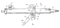
- FIG. 1 is a side view of an impact absorption type steering column apparatus for a vehicle in an embodiment of the present invention
- FIG. 2 is a plan view of the impact absorption type steering column apparatus for the vehicle shown in FIG. 1 ;
- FIG. 3 is a sectional view taken along the line A—A in FIG. 1 ;
- FIG. 4 is a side view showing a state where the impact absorption type steering column apparatus for the vehicle shown in FIG. 1 is mounted in an actual car;
- FIG. 5 is a side view showing a secondary collision in the state where the impact absorption type steering column apparatus for the vehicle is mounted in the actual car;
- FIG. 6 is a side view of the impact absorption type steering column apparatus for the vehicle in another embodiment of the present invention.
- FIG. 7 is a side view showing a state where an impact absorption type steering column apparatus for a vehicle in the prior art is mounted in an actual car.
- FIG. 1 is a side view of the impact absorption type steering column apparatus for the vehicle according to the embodiment of the present invention.
- FIG. 2 is a plan view of the impact absorption type steering column apparatus for the vehicle shown in FIG. 1 .
- FIG. 3 is a sectional view taken along the line A—A in FIG. 1 .
- FIG. 4 is a side view showing a state where the impact absorption type steering column apparatus for the vehicle is mounted in an actual car.
- FIG. 5 is a side view showing the state where the impact absorption type steering column apparatus for the vehicle is mounted in the actual car, and also showing a state of the secondary collision.
- FIG. 6 is a side view of the impact absorption type steering column apparatus for the vehicle in another embodiment of the present invention.
- a steering shaft 2 is rotatably supported within a steering column 1 to which a steering wheel (that is not shown in FIGS. 1 and 2 ) is fixed on the right side end in FIG. 1 .
- This steering column 1 is secured to a car body through a lower bracket 3 at its lower end portion and a car body securing bracket 4 (a tilt bracket) taking substantially an L-shape as viewed from its side at its middle portion.
- the lower bracket 3 is formed with a cut-away portion opened to the front of the vehicle, and a tilt center bolt 7 fitted to the bracket 6 of the steering column 1 is engaged with this cut-away portion 5 .
- the car body securing bracket 4 taking substantially the L-shape as viewed from its side is constructed integrally of a car body securing portion 10 for securing to the car body through a bolt, etc. extending in the horizontal direction in FIG. 3 , a couple of plate-shaped support wall portions 12 , 12 bent substantially in the L-shape as viewed from the side through a bent portion 11 from this car body securing portion 10 and extending in the transversal direction of the steering column 1 , and a couple of plate-shaped column fastening fixation portions 14 , 14 erected from the couple of plate-shaped support wall portions 12 , 12 and extending in the axial directions on both sides of the steering column 1 .
- These column fastening fixation portions 14 , 14 are formed respectively with tilt adjustment grooves 13 , 13 for adjusting the steering column in a tilt adjusting position.
- a distance bracket 15 fixed by welding, etc. to the steering column 1 is provided in a way that brings both of side end surfaces of this bracket 15 into contact with the insides of the couple of column fastening fixation portions 14 , 14 of the car body securing bracket (the tilt bracket) 4 .
- a fastening bolt 16 is inserted through the couple of tilt adjustment grooves 13 , 13 of the couple of column fastening fixation portions 14 , 14 and through the both side end surfaces of the distance bracket 15 .
- a fastening lever 17 is secured to a proximal end portion of this fastening bolt 16 .
- the proximal end portion of the fastening bolt 16 is provided with a cam lock mechanism provided with a first cam 18 rotating with the fastening lever 17 and a non-rotatable second cam 19 engaging with and thus locked to the first cam 18 .
- the fastening lever 17 is swayable between a fastening position and a unfastening position, and, when rotated to the fastening position, the steering column 1 is fixed to the tilt adjusted position in a way that fixedly abuts the two side end surfaces of the distance bracket 15 by pressing through the couple of column fastening fixation portions 14 , 14 of the car body securing bracket 4 by dint of a function of the cam lock mechanism.
- the fastening lever 17 is rotated to the unfastening position, the distance bracket 15 is unfastened, whereby the steering column comes into a tilt position adjustable state.
- the fastening lever 17 is constructed so that when the fastening lever 17 is in a state of being fixed to the tilt adjusted position, a portion to be hand-held of the fastening lever 17 is disposed on the more anterior side of the vehicle than the proximal end portion 17 a thereof.
- the bent portion 11 of the car body securing bracket 4 is formed with a reinforcing bead 11 a , wherein a bending load occurred when the second collision happens can be adjusted by changing a size of this reinforcing bead 11 a.
- the bent portion 11 and the couple of plate-shaped support wall portions 12 , 12 are disposed at the rear side of the vehicle on the car body securing portion 10 of the car body securing bracket 4 , and the couple of column fastening fixation portions 14 , 14 are disposed at the front side of the vehicle on the plate-shaped support wall portions 12 , 12 .
- the fastening bolt 16 is thereby positioned below the bent portion 11 substantially in the vertical direction.
- the fastening bolt 16 is disposed below the bent portion 11 substantially in the vertical direction.
- the fastening bolt 16 starts moving, as indicated by an arrowhead (x) in FIG. 4 , substantially in the horizontal direction with the bent portion 11 used as a fulcrum, and subsequently rotates about the bent portion 11 (fulcrum) as indicated by an arrowhead (y).
- the impact absorption type steering column apparatus for the vehicle in this embodiment gets collapsed while causing its flexural deformation in such a way that the couple of plate-shaped support wall portions 12 , 12 of the car body securing bracket 4 and the couple of column fastening fixation portions 14 , 14 rotate about the bent portion (fulcrum) 11 , thereby absorbing an energy of the secondary impact.
- the bent portion 11 and the couple of plate-shaped support wall portions 12 , 12 are disposed at the rear side of the vehicle on the car body securing portion 10 , and the couple of column fastening fixation portions 14 , 14 are disposed at the front side of the vehicle on these plate-shaped support wall portions 12 , 12 .
- the couple of plate-shaped support wall portions 12 , 12 of the car body securing bracket 4 and the couple of column fastening fixation portions 14 , 14 start moving in the direction of their rotating about the bent portion 11 serving as the fulcrum, however, this direction is substantially the horizontal direction and is substantially coincident with an input direction (substantially the horizontal direction) of the load of the impact from the driver. Accordingly, the start of motion of the car body securing bracket 4 at the secondary collision can be stabilized.
- the portion to be hand-held 17 b of the fastening lever 17 is disposed at a more anterior side of the vehicle than the proximal end portion 17 a thereof.
- the fastening lever 17 following up the collapse of the car body securing bracket 4 , moves towards the front of the vehicle while rotating, whereby safety against the collision on the knee of a passenger can be further enhanced.
- FIG. 6 shows a side view of the impact absorption type steering column apparatus for the vehicle in still another embodiment of the present invention.
- a different point of this embodiment from the embodiment discussed above lies in a structure of the car body securing bracket.
- a bent portion 111 and a couple of plate-shaped support wall portions 112 , 112 are disposed at the front side of the vehicle on a car body securing portion 110 of a car body securing bracket 104 .
- a couple of column fastening fixation portions 114 , 114 are disposed at the rear side of the vehicle on the plate-shaped support wall portions 112 , 112 and are formed respectively with tilt adjustment grooves 113 , 113 .
- Other constructions are the same as those-in the embodiment discussed above and marked with the same symbols, and their explanations are omitted.
- the secondary impact load acts toward the front from the rear of the vehicle, with the result that the steering column 1 is forced to move toward the front side of the vehicle together with a distance bracket 15 and a fastening bolt 16 .
- the fastening bolt 16 starts moving, with the bent portion 111 serving as a fulcrum, in a direction considerably downwards from the horizontal direction and rotates about the bent portion (fulcrum) 111 .
- the impact absorption type steering column apparatus gets collapsed while causing its flexural deformation in such a way that the couple of plate-shaped support wall portions 112 , 112 of the car body securing bracket 104 and the couple of column fastening fixation portions 114 , 114 rotate about the bent portion (fulcrum) 111 , thereby absorbing an energy of the secondary impact.
- the portion to be hand-held 17 b of the fastening lever 17 is disposed at the more anterior side of the vehicle than the proximal end portion 17 a thereof, and, besides, when the secondary collision happens, the fastening lever 17 , following the collapse of the car body securing bracket 104 , moves towards the front of the vehicle while rotating, whereby safety against the collision on the knee of the passenger can be further enhanced.
- the present invention is not limited to the embodiments discussed above and can be modified in many ways.
- the present invention is applied to the car body securing bracket (the tilt bracket) and may also be applied to the lower bracket.
Landscapes
- Engineering & Computer Science (AREA)
- Mechanical Engineering (AREA)
- Chemical & Material Sciences (AREA)
- Combustion & Propulsion (AREA)
- Transportation (AREA)
- Steering Controls (AREA)
Applications Claiming Priority (5)
| Application Number | Priority Date | Filing Date | Title |
|---|---|---|---|
| JP2001279687 | 2001-09-14 | ||
| JP2001-279687 | 2001-09-14 | ||
| JP2002262949A JP2003160051A (ja) | 2001-09-14 | 2002-09-09 | 車両用衝撃吸収式ステアリングコラム装置 |
| JP2002-262949 | 2002-09-09 | ||
| PCT/JP2002/009258 WO2003024763A1 (fr) | 2001-09-14 | 2002-09-11 | Dispositif colonne de direction absorbant les chocs pour vehicules |
Publications (2)
| Publication Number | Publication Date |
|---|---|
| US20040094945A1 US20040094945A1 (en) | 2004-05-20 |
| US7125046B2 true US7125046B2 (en) | 2006-10-24 |
Family
ID=26622234
Family Applications (1)
| Application Number | Title | Priority Date | Filing Date |
|---|---|---|---|
| US10/415,486 Expired - Lifetime US7125046B2 (en) | 2001-09-14 | 2002-09-11 | Shock absorbing steering column device for vehicle |
Country Status (5)
| Country | Link |
|---|---|
| US (1) | US7125046B2 (ja) |
| JP (1) | JP2003160051A (ja) |
| DE (1) | DE10294486B4 (ja) |
| GB (1) | GB2395467B (ja) |
| WO (1) | WO2003024763A1 (ja) |
Cited By (7)
| Publication number | Priority date | Publication date | Assignee | Title |
|---|---|---|---|---|
| US20050093284A1 (en) * | 2002-07-02 | 2005-05-05 | Kenji Sato | Shock absorbing steering column device for vehicle |
| US20050167962A1 (en) * | 2002-07-10 | 2005-08-04 | Kenji Sato | Vehicle shock absorption type steering column device |
| US20080116677A1 (en) * | 2004-10-28 | 2008-05-22 | Faurecia Interieur Industrie | Connecting Device Between the Steering Column and the Body of a Motor Vehicle |
| DE102008011618B3 (de) * | 2008-02-28 | 2009-07-30 | Thyssenkrupp Presta Ag | Lenksäule für ein Kraftfahrzeug |
| DE102008011620A1 (de) | 2008-02-28 | 2009-10-29 | Thyssenkrupp Presta Ag | Verstellbare Lenksäule für ein Kraftfahrzeug |
| DE102008045143A1 (de) | 2008-09-01 | 2010-03-18 | Thyssenkrupp Presta Ag | Verstellbare Lenksäule für ein Kraftfahrzeug |
| DE102010000504B3 (de) * | 2010-02-22 | 2011-03-03 | Thyssenkrupp Presta Ag | Verstellbare Lenksäule für ein Kraftfahrzeug |
Families Citing this family (6)
| Publication number | Priority date | Publication date | Assignee | Title |
|---|---|---|---|---|
| JP2004203164A (ja) * | 2002-12-25 | 2004-07-22 | Fuji Kiko Co Ltd | 車両用ステアリング装置の衝撃吸収構造 |
| JP4721428B2 (ja) * | 2003-10-20 | 2011-07-13 | 日本精工株式会社 | ステアリング装置 |
| JP5874361B2 (ja) * | 2011-12-05 | 2016-03-02 | 日本精工株式会社 | ステアリング装置の製造方法 |
| JP6403334B2 (ja) * | 2015-03-09 | 2018-10-10 | 株式会社ジェイテクト | ステアリング装置 |
| JP6065992B2 (ja) * | 2016-01-20 | 2017-01-25 | 日本精工株式会社 | ステアリング装置 |
| JP6119890B2 (ja) * | 2016-02-18 | 2017-04-26 | 日本精工株式会社 | ステアリング装置 |
Citations (18)
| Publication number | Priority date | Publication date | Assignee | Title |
|---|---|---|---|---|
| JPS59101021A (ja) | 1982-11-29 | 1984-06-11 | Olympus Optical Co Ltd | 磁気ヘツドの生産方法 |
| JPS615263U (ja) | 1984-06-18 | 1986-01-13 | 日本精工株式会社 | ステアリングハンドルの位置調整装置 |
| JPS626073U (ja) | 1985-06-28 | 1987-01-14 | ||
| US4648624A (en) | 1985-09-30 | 1987-03-10 | Cycles Peugeot | Fixing device for a tubular part, in particular for the steering column of a vehicle |
| JPS6259162A (ja) | 1985-09-06 | 1987-03-14 | Fuji Kiko Co Ltd | チルト式ステアリングコラム装置 |
| JPS6251078U (ja) | 1985-09-20 | 1987-03-30 | ||
| US4733575A (en) * | 1986-04-17 | 1988-03-29 | Toyota Jidosha Kabushiki Kaisha | Vehicle tilt steering column device including a bending bracket type energy absorbing means |
| US5294149A (en) | 1991-02-15 | 1994-03-15 | Nacam | Steering column device for motor vehicles |
| US5593183A (en) | 1994-01-06 | 1997-01-14 | Nacam | Energy-absorbing device for vehicle steering column |
| EP0770536A2 (en) | 1995-10-24 | 1997-05-02 | FIAT AUTO S.p.A. | A lever device for releasing or freeing a steering wheel from the steering column for adjustment |
| EP0816205A2 (en) | 1996-07-02 | 1998-01-07 | Fuji Kiko Co., Ltd. | Steering column assembly for vehicle |
| US5730465A (en) * | 1995-09-11 | 1998-03-24 | Nastech Europe Limited | Adjustable vehicle steering column clamping mechanism |
| JP2978788B2 (ja) | 1995-10-20 | 1999-11-15 | 富士機工株式会社 | 自動車用ステアリングコラム |
| JP2000229577A (ja) | 1999-02-10 | 2000-08-22 | Fuji Kiko Co Ltd | ステアリングコラムのエネルギー吸収構造 |
| EP1083109A2 (en) | 1999-09-10 | 2001-03-14 | Koyo Seiko Co., Ltd. | Shock-absorbing steering assembly |
| US6282978B1 (en) * | 1998-10-09 | 2001-09-04 | Fuji Kiko Co., Ltd. | Tilt-lock device for tilt-type steering column |
| EP1223096A1 (en) | 2001-01-11 | 2002-07-17 | FUJI KIKO Co., Ltd. | Steering column assembly for a vehicle |
| US6799779B2 (en) * | 2001-10-23 | 2004-10-05 | Fuji Kiko Co., Ltd. | Shock-absorbing tilt type steering column |
Family Cites Families (1)
| Publication number | Priority date | Publication date | Assignee | Title |
|---|---|---|---|---|
| DE69600661T2 (de) * | 1995-10-20 | 1999-02-04 | Fuji Kiko Kk | Lenksäule für ein Kraftfahrzeug |
-
2002
- 2002-09-09 JP JP2002262949A patent/JP2003160051A/ja active Pending
- 2002-09-11 US US10/415,486 patent/US7125046B2/en not_active Expired - Lifetime
- 2002-09-11 GB GB0309822A patent/GB2395467B/en not_active Expired - Fee Related
- 2002-09-11 DE DE10294486T patent/DE10294486B4/de not_active Expired - Fee Related
- 2002-09-11 WO PCT/JP2002/009258 patent/WO2003024763A1/ja active Application Filing
Patent Citations (26)
| Publication number | Priority date | Publication date | Assignee | Title |
|---|---|---|---|---|
| JPS59101021A (ja) | 1982-11-29 | 1984-06-11 | Olympus Optical Co Ltd | 磁気ヘツドの生産方法 |
| JPS615263U (ja) | 1984-06-18 | 1986-01-13 | 日本精工株式会社 | ステアリングハンドルの位置調整装置 |
| JPS626073U (ja) | 1985-06-28 | 1987-01-14 | ||
| JPS6259162A (ja) | 1985-09-06 | 1987-03-14 | Fuji Kiko Co Ltd | チルト式ステアリングコラム装置 |
| JPS6251078U (ja) | 1985-09-20 | 1987-03-30 | ||
| JPS6274767A (ja) | 1985-09-30 | 1987-04-06 | シイクル プジヨ− | 筒状体のための固定装置 |
| EP0222628A1 (fr) | 1985-09-30 | 1987-05-20 | Ecia - Equipements Et Composants Pour L'industrie Automobile | Dispositif de fixation pour une pièce tubulaire, en particulier pour une colonne de direction de véhicule |
| US4648624A (en) | 1985-09-30 | 1987-03-10 | Cycles Peugeot | Fixing device for a tubular part, in particular for the steering column of a vehicle |
| US4733575A (en) * | 1986-04-17 | 1988-03-29 | Toyota Jidosha Kabushiki Kaisha | Vehicle tilt steering column device including a bending bracket type energy absorbing means |
| US5294149A (en) | 1991-02-15 | 1994-03-15 | Nacam | Steering column device for motor vehicles |
| DE69200931T2 (de) | 1991-02-15 | 1995-04-20 | Nacam | Lenksäulen-Anordnung für ein Kraftfahrzeug. |
| US5593183A (en) | 1994-01-06 | 1997-01-14 | Nacam | Energy-absorbing device for vehicle steering column |
| US5730465A (en) * | 1995-09-11 | 1998-03-24 | Nastech Europe Limited | Adjustable vehicle steering column clamping mechanism |
| JP2978788B2 (ja) | 1995-10-20 | 1999-11-15 | 富士機工株式会社 | 自動車用ステアリングコラム |
| EP0770536A2 (en) | 1995-10-24 | 1997-05-02 | FIAT AUTO S.p.A. | A lever device for releasing or freeing a steering wheel from the steering column for adjustment |
| DE69615309T2 (de) | 1995-10-24 | 2002-07-04 | Fiat Auto Spa | Hebelvorrichtung zum Entkuppeln oder Lösen eines Lenkrades von der Lenksäule zur Verstellung |
| JPH1016796A (ja) | 1996-07-02 | 1998-01-20 | Fuji Kiko Co Ltd | 車両用ステアリングコラム |
| US5857703A (en) * | 1996-07-02 | 1999-01-12 | Fuji Kiko Co., Ltd. | Steering column assembly for vehicle |
| EP0816205A2 (en) | 1996-07-02 | 1998-01-07 | Fuji Kiko Co., Ltd. | Steering column assembly for vehicle |
| US6282978B1 (en) * | 1998-10-09 | 2001-09-04 | Fuji Kiko Co., Ltd. | Tilt-lock device for tilt-type steering column |
| US20020026848A1 (en) * | 1998-10-09 | 2002-03-07 | Haruhide Kurita | Tilt-lock device for tilt-type steering column |
| JP2000229577A (ja) | 1999-02-10 | 2000-08-22 | Fuji Kiko Co Ltd | ステアリングコラムのエネルギー吸収構造 |
| EP1083109A2 (en) | 1999-09-10 | 2001-03-14 | Koyo Seiko Co., Ltd. | Shock-absorbing steering assembly |
| JP2001080527A (ja) | 1999-09-10 | 2001-03-27 | Koyo Seiko Co Ltd | 衝撃吸収式ステアリング装置 |
| EP1223096A1 (en) | 2001-01-11 | 2002-07-17 | FUJI KIKO Co., Ltd. | Steering column assembly for a vehicle |
| US6799779B2 (en) * | 2001-10-23 | 2004-10-05 | Fuji Kiko Co., Ltd. | Shock-absorbing tilt type steering column |
Cited By (16)
| Publication number | Priority date | Publication date | Assignee | Title |
|---|---|---|---|---|
| US7384070B2 (en) * | 2002-07-02 | 2008-06-10 | Nsk, Ltd. | Shock absorbing steering column device for vehicle |
| US20050093284A1 (en) * | 2002-07-02 | 2005-05-05 | Kenji Sato | Shock absorbing steering column device for vehicle |
| US20050167962A1 (en) * | 2002-07-10 | 2005-08-04 | Kenji Sato | Vehicle shock absorption type steering column device |
| US7311333B2 (en) * | 2002-07-10 | 2007-12-25 | Nsk, Ltd. | Vehicle shock absorption type steering column device |
| US7673903B2 (en) * | 2004-10-28 | 2010-03-09 | Faurecia Interieur Industrie | Connecting device between the steering column and the body of a motor vehicle |
| US20080116677A1 (en) * | 2004-10-28 | 2008-05-22 | Faurecia Interieur Industrie | Connecting Device Between the Steering Column and the Body of a Motor Vehicle |
| DE102008011618B3 (de) * | 2008-02-28 | 2009-07-30 | Thyssenkrupp Presta Ag | Lenksäule für ein Kraftfahrzeug |
| DE102008011620A1 (de) | 2008-02-28 | 2009-10-29 | Thyssenkrupp Presta Ag | Verstellbare Lenksäule für ein Kraftfahrzeug |
| DE102008011620B4 (de) * | 2008-02-28 | 2010-02-18 | Thyssenkrupp Presta Ag | Verstellbare Lenksäule für ein Kraftfahrzeug |
| DE102008045143A1 (de) | 2008-09-01 | 2010-03-18 | Thyssenkrupp Presta Ag | Verstellbare Lenksäule für ein Kraftfahrzeug |
| US20110156380A1 (en) * | 2008-09-01 | 2011-06-30 | Maximilian Dietz | Adjustable steering column for a motor vehicle |
| DE102008045143B4 (de) * | 2008-09-01 | 2012-05-24 | Thyssenkrupp Presta Ag | Verstellbare Lenksäule für ein Kraftfahrzeug |
| US8590932B2 (en) * | 2008-09-01 | 2013-11-26 | Thyssenkrupp Presta Aktiengesellschaft | Adjustable steering column for a motor vehicle |
| DE102010000504B3 (de) * | 2010-02-22 | 2011-03-03 | Thyssenkrupp Presta Ag | Verstellbare Lenksäule für ein Kraftfahrzeug |
| WO2011100770A1 (de) | 2010-02-22 | 2011-08-25 | Thyssenkrupp Presta Aktiengesellschaft | Verstellbare lenksäule für ein kraftfahrzeug |
| US8905436B2 (en) | 2010-02-22 | 2014-12-09 | Thyssenkrupp Presta Aktiengesellschaft | Adjustable steering column for a motor vehicle |
Also Published As
| Publication number | Publication date |
|---|---|
| GB2395467B (en) | 2006-03-08 |
| US20040094945A1 (en) | 2004-05-20 |
| JP2003160051A (ja) | 2003-06-03 |
| DE10294486B4 (de) | 2009-04-09 |
| DE10294486T1 (de) | 2003-10-16 |
| GB2395467A (en) | 2004-05-26 |
| WO2003024763A1 (fr) | 2003-03-27 |
Similar Documents
| Publication | Publication Date | Title |
|---|---|---|
| US6688644B2 (en) | Steering apparatus | |
| US7125046B2 (en) | Shock absorbing steering column device for vehicle | |
| US7311333B2 (en) | Vehicle shock absorption type steering column device | |
| US6702324B2 (en) | Knee bolster | |
| US5547221A (en) | Energy absorbing member for shock absorbing steering column apparatus | |
| CN108357560B (zh) | 转向管柱 | |
| EP1518775B1 (en) | Shock absorbing steering column device for vehicle | |
| JP2007284034A (ja) | ニーボルスタおよび乗員下肢保護方法並にニーボルスタを備えた自動車 | |
| US6345842B1 (en) | Shock absorbing type steering apparatus and a structure for mounting to an automobile body the steering apparatus | |
| US20040090057A1 (en) | Collapsing steering column with locking tilt mechanism | |
| JP2513633Y2 (ja) | 衝撃吸収式ステアリングコラム装置 | |
| JP2978788B2 (ja) | 自動車用ステアリングコラム | |
| US6148687A (en) | Steering column for automotive vehicle | |
| JP2005096731A (ja) | 衝撃吸収式ステアリングコラム装置 | |
| CN115465353A (zh) | 转向装置 | |
| KR20140065844A (ko) | 자동차의 스티어링 컬럼 장치 | |
| GB2408242A (en) | Impact absorbing steering column for a vehicle | |
| JP4258274B2 (ja) | 車両用衝撃吸収式ステアリングコラム装置 | |
| JP2003026006A (ja) | 衝撃吸収ステアリング装置 | |
| JP2002308117A (ja) | 衝撃吸収式ステアリング装置 | |
| KR100844943B1 (ko) | 충격 흡수식 자동차의 스티어링칼럼 | |
| JP4211367B2 (ja) | 衝撃吸収式ステアリングコラム装置 | |
| JP2513593Y2 (ja) | 衝撃吸収式ステアリング装置 | |
| KR100844944B1 (ko) | 충격 흡수식 자동차의 스티어링칼럼 | |
| JP2010083436A (ja) | 衝撃吸収式ステアリングコラム装置 |
Legal Events
| Date | Code | Title | Description |
|---|---|---|---|
| AS | Assignment |
Owner name: NSK LTD., JAPAN Free format text: ASSIGNMENT OF ASSIGNORS INTEREST;ASSIGNORS:SAWADA, NAOKI;SATO, KENJI;REEL/FRAME:014226/0190 Effective date: 20030409 |
|
| STCF | Information on status: patent grant |
Free format text: PATENTED CASE |
|
| FPAY | Fee payment |
Year of fee payment: 4 |
|
| FPAY | Fee payment |
Year of fee payment: 8 |
|
| MAFP | Maintenance fee payment |
Free format text: PAYMENT OF MAINTENANCE FEE, 12TH YEAR, LARGE ENTITY (ORIGINAL EVENT CODE: M1553) Year of fee payment: 12 |