US6845686B2 - Cam follower with roller - Google Patents
Cam follower with roller Download PDFInfo
- Publication number
- US6845686B2 US6845686B2 US10/223,320 US22332002A US6845686B2 US 6845686 B2 US6845686 B2 US 6845686B2 US 22332002 A US22332002 A US 22332002A US 6845686 B2 US6845686 B2 US 6845686B2
- Authority
- US
- United States
- Prior art keywords
- roller
- shaft
- cam follower
- supporting
- volume
- Prior art date
- Legal status (The legal status is an assumption and is not a legal conclusion. Google has not performed a legal analysis and makes no representation as to the accuracy of the status listed.)
- Expired - Lifetime, expires
Links
Images


Classifications
-
- F—MECHANICAL ENGINEERING; LIGHTING; HEATING; WEAPONS; BLASTING
- F16—ENGINEERING ELEMENTS AND UNITS; GENERAL MEASURES FOR PRODUCING AND MAINTAINING EFFECTIVE FUNCTIONING OF MACHINES OR INSTALLATIONS; THERMAL INSULATION IN GENERAL
- F16C—SHAFTS; FLEXIBLE SHAFTS; ELEMENTS OR CRANKSHAFT MECHANISMS; ROTARY BODIES OTHER THAN GEARING ELEMENTS; BEARINGS
- F16C13/00—Rolls, drums, discs, or the like; Bearings or mountings therefor
- F16C13/006—Guiding rollers, wheels or the like, formed by or on the outer element of a single bearing or bearing unit, e.g. two adjacent bearings, whose ratio of length to diameter is generally less than one
-
- F—MECHANICAL ENGINEERING; LIGHTING; HEATING; WEAPONS; BLASTING
- F01—MACHINES OR ENGINES IN GENERAL; ENGINE PLANTS IN GENERAL; STEAM ENGINES
- F01L—CYCLICALLY OPERATING VALVES FOR MACHINES OR ENGINES
- F01L1/00—Valve-gear or valve arrangements, e.g. lift-valve gear
- F01L1/12—Transmitting gear between valve drive and valve
- F01L1/18—Rocking arms or levers
- F01L1/181—Centre pivot rocking arms
-
- F—MECHANICAL ENGINEERING; LIGHTING; HEATING; WEAPONS; BLASTING
- F01—MACHINES OR ENGINES IN GENERAL; ENGINE PLANTS IN GENERAL; STEAM ENGINES
- F01L—CYCLICALLY OPERATING VALVES FOR MACHINES OR ENGINES
- F01L1/00—Valve-gear or valve arrangements, e.g. lift-valve gear
- F01L1/26—Valve-gear or valve arrangements, e.g. lift-valve gear characterised by the provision of two or more valves operated simultaneously by same transmitting-gear; peculiar to machines or engines with more than two lift-valves per cylinder
- F01L1/267—Valve-gear or valve arrangements, e.g. lift-valve gear characterised by the provision of two or more valves operated simultaneously by same transmitting-gear; peculiar to machines or engines with more than two lift-valves per cylinder with means for varying the timing or the lift of the valves
-
- F—MECHANICAL ENGINEERING; LIGHTING; HEATING; WEAPONS; BLASTING
- F16—ENGINEERING ELEMENTS AND UNITS; GENERAL MEASURES FOR PRODUCING AND MAINTAINING EFFECTIVE FUNCTIONING OF MACHINES OR INSTALLATIONS; THERMAL INSULATION IN GENERAL
- F16C—SHAFTS; FLEXIBLE SHAFTS; ELEMENTS OR CRANKSHAFT MECHANISMS; ROTARY BODIES OTHER THAN GEARING ELEMENTS; BEARINGS
- F16C19/00—Bearings with rolling contact, for exclusively rotary movement
- F16C19/22—Bearings with rolling contact, for exclusively rotary movement with bearing rollers essentially of the same size in one or more circular rows, e.g. needle bearings
- F16C19/44—Needle bearings
- F16C19/46—Needle bearings with one row or needles
-
- F—MECHANICAL ENGINEERING; LIGHTING; HEATING; WEAPONS; BLASTING
- F16—ENGINEERING ELEMENTS AND UNITS; GENERAL MEASURES FOR PRODUCING AND MAINTAINING EFFECTIVE FUNCTIONING OF MACHINES OR INSTALLATIONS; THERMAL INSULATION IN GENERAL
- F16C—SHAFTS; FLEXIBLE SHAFTS; ELEMENTS OR CRANKSHAFT MECHANISMS; ROTARY BODIES OTHER THAN GEARING ELEMENTS; BEARINGS
- F16C33/00—Parts of bearings; Special methods for making bearings or parts thereof
- F16C33/30—Parts of ball or roller bearings
- F16C33/58—Raceways; Race rings
- F16C33/62—Selection of substances
-
- F—MECHANICAL ENGINEERING; LIGHTING; HEATING; WEAPONS; BLASTING
- F16—ENGINEERING ELEMENTS AND UNITS; GENERAL MEASURES FOR PRODUCING AND MAINTAINING EFFECTIVE FUNCTIONING OF MACHINES OR INSTALLATIONS; THERMAL INSULATION IN GENERAL
- F16H—GEARING
- F16H53/00—Cams ; Non-rotary cams; or cam-followers, e.g. rollers for gearing mechanisms
- F16H53/06—Cam-followers
-
- F—MECHANICAL ENGINEERING; LIGHTING; HEATING; WEAPONS; BLASTING
- F01—MACHINES OR ENGINES IN GENERAL; ENGINE PLANTS IN GENERAL; STEAM ENGINES
- F01L—CYCLICALLY OPERATING VALVES FOR MACHINES OR ENGINES
- F01L2305/00—Valve arrangements comprising rollers
-
- F—MECHANICAL ENGINEERING; LIGHTING; HEATING; WEAPONS; BLASTING
- F01—MACHINES OR ENGINES IN GENERAL; ENGINE PLANTS IN GENERAL; STEAM ENGINES
- F01L—CYCLICALLY OPERATING VALVES FOR MACHINES OR ENGINES
- F01L2305/00—Valve arrangements comprising rollers
- F01L2305/02—Mounting of rollers
-
- F—MECHANICAL ENGINEERING; LIGHTING; HEATING; WEAPONS; BLASTING
- F16—ENGINEERING ELEMENTS AND UNITS; GENERAL MEASURES FOR PRODUCING AND MAINTAINING EFFECTIVE FUNCTIONING OF MACHINES OR INSTALLATIONS; THERMAL INSULATION IN GENERAL
- F16C—SHAFTS; FLEXIBLE SHAFTS; ELEMENTS OR CRANKSHAFT MECHANISMS; ROTARY BODIES OTHER THAN GEARING ELEMENTS; BEARINGS
- F16C2360/00—Engines or pumps
- F16C2360/18—Camshafts
-
- F—MECHANICAL ENGINEERING; LIGHTING; HEATING; WEAPONS; BLASTING
- F16—ENGINEERING ELEMENTS AND UNITS; GENERAL MEASURES FOR PRODUCING AND MAINTAINING EFFECTIVE FUNCTIONING OF MACHINES OR INSTALLATIONS; THERMAL INSULATION IN GENERAL
- F16H—GEARING
- F16H55/00—Elements with teeth or friction surfaces for conveying motion; Worms, pulleys or sheaves for gearing mechanisms
- F16H55/02—Toothed members; Worms
- F16H55/06—Use of materials; Use of treatments of toothed members or worms to affect their intrinsic material properties
-
- Y—GENERAL TAGGING OF NEW TECHNOLOGICAL DEVELOPMENTS; GENERAL TAGGING OF CROSS-SECTIONAL TECHNOLOGIES SPANNING OVER SEVERAL SECTIONS OF THE IPC; TECHNICAL SUBJECTS COVERED BY FORMER USPC CROSS-REFERENCE ART COLLECTIONS [XRACs] AND DIGESTS
- Y10—TECHNICAL SUBJECTS COVERED BY FORMER USPC
- Y10T—TECHNICAL SUBJECTS COVERED BY FORMER US CLASSIFICATION
- Y10T74/00—Machine element or mechanism
- Y10T74/21—Elements
- Y10T74/2101—Cams
- Y10T74/2107—Follower
Definitions
- the present invention relates to a cam follower with roller, and more particularly, to a cam follower with roller that is incorporated into a valve mechanism of an internal combustion engine of a vehicle.
- a combustion engine having a variable valve timing mechanism such as a VTEC (Variable Valve Timing & Lift Electronic Control System) is generally known.
- VTEC Variable Valve Timing & Lift Electronic Control System
- a valve mechanism is configured such that two driving locker arms and a connecting locker arm connecting them actuate together when operated at a high speed, whereas the two driving locker arms actuate separately when operated at a low speed.
- a roller contacting a cam is supported by a needle bearing.
- SUJ2 is used in the driving locker arms
- carburized steel is used in the connecting locker arm.
- a switching pin does not actuate, generating a small load applied on the needle bearing supporting the roller.
- an SUJ2 material is used for the driving locker arms.
- the switching pin actuates so that the shafts of the driving locker arms and the connecting locker arm are connected, generating an excessive load applied on the needle bearing supporting the roller in the connecting locker arm.
- the bearing must therefore have a large width in order to ensure long life.
- the driving locker arms and the connecting locker arm actuate together by the actuation of the switching pin, which may cause a problem of shaft bending that originates from the side of the inner diameter of the shaft.
- This is addressed by increasing the width of the bearing and by using a tough carburized material for the supporting shaft of the roller in the connecting locker arm.
- the SUJ2 material used here is quenched and tempered such that the hardness of a rolling surface of the needle roller is adjusted to HRC 60 to 62.
- the roller supported by the locker arms is in direct contact with the cam. In this portion, lubrication easily dies away compared to other engine components, and thus the contact surface of the cam and roller is called a boundary lubrication region.
- the needle roller supporting the roller is in contact with the shaft basically in a manner of rolling contact. Under the severe circumstances as described above, however, small sliding occurs between the needle roller and the shaft when the cam load varies rapidly. This makes the needle roller bearing have poor lubrication, causing abrasion and the like, resulting in insufficient durability. Furthermore, as the cam load increases, the pressure on the contacting surface of the needle roller and the shaft also increases, shortening fatigue life.
- An object of the present invention is to provide a cam follower with roller having excellent durability and fatigue life.
- a cam follower with roller of the present invention including a cam follower body having a roller supporting portion integrated into the cam follower body, a supporting shaft having both ends fixed to the roller supporting portion, and a roller rotatably supported on the supporting shaft with a plurality of needle rollers interposed, at least one of the supporting shaft and needle roller has a surface on which a nitride layer is formed, and has a surface hardness of at least HV 650 and an amount of retained austenite of at least 25% by volume and at most 50% by volume.
- a process that involves nitriding is performed to increase the surface hardness to at most HV 650, and to increase the amount of retained austenite to at least 25% by volume and at most 50% by volume. This can reduce abrasion occurring between the supporting shaft and the needle roller and can improve fatigue strength, exhibiting excellent durability and rolling fatigue life.
- nitriding is performed, so that a nitride layer is formed on the surface of one of the supporting shaft and needle roller.
- the amount of retained austenite is less than 25% by volume. Further, if the amount of retained austenite is greater than 50% by volume, the surface hardness is lowered, deteriorating abrasion resistance. Thus, the amount of retained austenite must be at least 25% by volume and at most 50% by volume.
- the surface hardness is smaller than 25% by volume, the supporting shaft is deformed due to abrasion occurring at rolling of the needle roller.
- the surface hardness must be at least HV 650.
- the cam follower with roller has a supporting shaft made of carburized steel and is subjected to carbonitriding followed by tempering.
- the supporting shaft of the cam follower with roller When the supporting shaft of the cam follower with roller is used in a high temperature range as in the present invention, it is tempered at an environmental temperature or higher in order to stabilize its dimension in the environment.
- both ends of the supporting shaft are preferably caulked and fixed to the roller supporting portion.
- the caulking and fixing work can be performed merely by notching an end surface of the supporting shaft, which prevents an impact on the roller supporting portion.
- the cam follower therefore would not be deformed at assembling.
- both end surfaces of the supporting shaft preferably have a surface hardness of at least HV 200 and at most HV 280 by no-quenching.
- the end surfaces of the supporting shaft can be notched so as to expand the edges thereof when the cam follower is assembled. Such a process of caulking and fixing would cause no cracks at the end portion, allowing the supporting shaft to be readily and firmly fixed to the cam follower body.
- the cam follower with roller has a supporting shaft made of bearing steel and is subjected to carbonitriding followed by tempering.
- the supporting shaft of the cam follower with roller When the supporting shaft of the cam follower with roller is used in a high temperature range as in the present invention, it is tempered at an environmental temperature or higher in order to stabilize its dimension in the environment.
- the supporting shaft is formed by a hollow shaft and is fixed to the roller supporting portion.
- variable valve timing mechanism such as VTEC may be implemented with a simple structure by arranging a switching pin at the hollow portion.
- FIG. 1 is a schematic front view showing a structure of a cam follower with roller according to one embodiment of the present invention
- FIG. 2 is a schematic section view taken along the II—II line in FIG. 1 ;
- FIG. 3 is a schematic section view taken along the II—II line in FIG. 1 , showing a structure when the cam follower with roller in FIG. 1 is used in a VTEC valve mechanism;
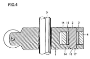
- FIG. 4 is a schematic section view showing a structure when a roller shaft has a solid body and is caulked and fixed;
- FIGS. 5A and 5B show a vertical section view and a hardness distribution line, respectively, of the roller shaft shown in FIG. 4 ;
- FIG. 6 is a section view schematically showing the structure of a test machine performing a life test.
- a cam follower body 1 is rotatably supported on a cam follower shaft 5 with a bearing metal or the like interposed at a middle portion.
- Adjust screw 7 is screwed into one end of cam follower body 1 .
- Adjust screw 7 is fixed by a lock nut 8 , and has its lower end being in contact with an upper end of a protruded rod 9 of a suction valve or an exhaust valve of an internal combustion engine.
- Protruded rod 9 is biased by resilience of a spring 10 .
- Cam follower body 1 has a roller supporting portion 14 integrally formed in a bifurcated manner at the other end thereof. Both ends of a roller shaft 2 are fixed to the bifurcated roller supporting portion 14 by press-fitting or by a snap ring.
- a roller 4 is rotatably supported on a middle portion of an outer circumferential surface of roller shaft 2 with a needle roller 3 interposed. The outer circumferential surface of roller 4 is pressed against a cam surface of cam 6 by biasing force of spring 10 .
- At least one of roller shaft 2 and needle roller 3 is subjected to a process that involves nitriding, thereby having a nitride layer on its surface, with a surface hardness of at least HV 650 and an amount of retained austenite at a superficial portion of at least 25% by volume and at most 50% by volume.
- roller shaft 2 is made of bearing steel and is subjected to carbonitriding followed by tempering.
- Roller shaft 2 is formed by e.g. a hollow shaft and is configured such that a switching pin may be arranged in a hollow portion.
- cam 6 By employing such a structure, rotation of cam 6 allows cam follower body 1 to rotate having cam follower shaft 5 as the center, with roller 4 interposed, to open and close a suction valve or an exhaust valve attached to a tip end of protruded rod 9 .
- the VTEC valve mechanism generally has driving locker arms RA 1 and RA 2 arranged at both sides, each of which is a cam follower with roller that is in contact with protruded rod 9 as shown in FIGS. 1 and 2 .
- Another cam follower with roller that is separated from protruded rod 9 in FIGS. 1 and 2 is provided between the two driving locker arms RA 1 and RA 2 as a connecting locker arm RA 3 .
- Connecting locker arm RA 3 connect driving locker arm RA 1 with driving locker arm RA 2 on both sides to actuate them together at high engine revolutions, whereas it actuates driving locker arms RA 1 and RA 2 separately at low engine revolutions.
- Each of roller shafts 2 , 2 a supporting each roller 4 , 4 a of these three locker arms RA 1 to RA 3 has a hollow shape, the hollow portion having two switching pins 11 a , 11 b arranged side-by-side therein.
- One end surface of switching pin 11 a abuts one end surface of switching pin 11 b
- the other end surface of switching pin 11 b is biased by a spring 12 toward switching pin 11 a .
- a hydraulic circuit 13 is provided on the other end surface of switching pin 11 a so as to be connected to the inside of the hollow portion in roller shaft 2 .
- switching pins 11 a , 11 b move to the left-hand side in the figure by the biasing force of spring 12 .
- the abutting surface of switching pins 11 a and 11 b is located at the boundary of locker arms RA 1 and RA 3
- the other end surface of switching pin 11 b is located at the boundary of locker arms RA 3 and RA 2 . This disconnects the three locker arms RA 1 to RA 3 from one another so that locker arms RA 1 to RA 3 actuate separately.
- three locker arms RA 1 to RA 3 can actuate together in a high-revolution range whereas they can actuate separately in a low-revolution range, allowing implementation of variable valve timing.
- each roller shaft 2 , 2 a and each needle roller 3 , 3 a in each of locker arms RA 1 to RA 3 is subjected to nitriding, whereby a nitride layer is formed on the surface.
- at least one of each roller shaft 2 , 2 a and each needle roller 3 , 3 a has a surface hardness of at least HV 650 and an amount of retained austenite on the surface layer is at least 25% by volume and at most 50% by volume.
- roller shaft 2 is not limited to have a hollow shape, and may have a solid structure as shown in FIG. 4 with both ends thereof caulked and fixed to roller supporting portion 14 .
- the caulking and fixing is performed by fitting roller shaft 2 into a shaft hole 15 provided at bifurcated roller supporting portion 14 and thereafter notching an end surface 16 of roller shaft 2 to form a caulking groove 17 .
- caulking groove 17 By forming caulking groove 17 , the edge portion of roller shaft 2 expands to bias the inner surface of shaft hole 15 by resilience, so that roller shaft 2 is firmly fixed to shaft hole 15 .
- a middle portion 2 c of roller shaft 2 is hardened by high-frequency quenching, and an end portion 2 d on either side is a not-quenched portion to which no quenching is provided.
- a part of or the entire outer circumferential surface of middle portion 2 c is a portion to be a rolling contact surface on which needle roller 3 rolls.
- middle portion 2 c has a Vickers hardness of at least HV 650, whereas a softened layer at each of both end portions 2 d has a Vickers hardness of at least HV 200 and at most HV 280.
- middle portion 2 c has a sufficient hardness as a rolling contact surface for needle roller 3 , while softened portion 2 d is sufficiently soft to be caulked.
- roller shaft 2 is made of carburized steel, and is subjected to carbonitriding followed by tempering.
- a life test was performed for carburized shaft and carbonitrided shaft using a test machine shown in FIG. 6 .
- a test machine configured to have a plurality of needle rollers 53 arranged to roll between a shaft 52 and an outer wheel 54 was used to perform the life test by rotating outer wheel 54 at a prescribed rate while a member 55 applies a radial load thereto.
- test condition is indicated in Table 1.
- the carburized shaft had the surface hardness of at least HV 650, the amount of retained austenite was 10% by volume.
- the carbonitrided shaft had a surface with a nitride layer formed thereon, and had the surface hardness of at least HV 650 and the amount of retained austenite of at least 25% by volume and at most 50% by volume.
- needle roller 53 may similarly be made of carburized steel or bearing steel subjected to nitriding, to obtain a surface hardness of at least HV 650 and an amount of retained austenite of at least 25% by volume and at most 50% by volume, greatly improving life as in the case above.
- a process that involves nitriding can be performed to increase a surface hardness to at least HV 650 and an amount of retained austenite to at least 25% by volume and at most 50% by volume. This can reduce abrasion occurring between a supporting shaft and a needle roller and can improve fatigue strength, allowing excellent durability and rolling fatigue life.
Landscapes
- Engineering & Computer Science (AREA)
- General Engineering & Computer Science (AREA)
- Mechanical Engineering (AREA)
- Valve-Gear Or Valve Arrangements (AREA)
- Rolling Contact Bearings (AREA)
- Valve Device For Special Equipments (AREA)
Applications Claiming Priority (2)
| Application Number | Priority Date | Filing Date | Title |
|---|---|---|---|
| JP2001-251103(P) | 2001-08-22 | ||
| JP2001251103A JP2003056315A (ja) | 2001-08-22 | 2001-08-22 | ローラ付きカムフォロア |
Publications (2)
| Publication Number | Publication Date |
|---|---|
| US20030037635A1 US20030037635A1 (en) | 2003-02-27 |
| US6845686B2 true US6845686B2 (en) | 2005-01-25 |
Family
ID=19079806
Family Applications (1)
| Application Number | Title | Priority Date | Filing Date |
|---|---|---|---|
| US10/223,320 Expired - Lifetime US6845686B2 (en) | 2001-08-22 | 2002-08-20 | Cam follower with roller |
Country Status (4)
| Country | Link |
|---|---|
| US (1) | US6845686B2 (de) |
| JP (1) | JP2003056315A (de) |
| CN (1) | CN1407211A (de) |
| DE (1) | DE10238252B4 (de) |
Cited By (4)
| Publication number | Priority date | Publication date | Assignee | Title |
|---|---|---|---|---|
| US20040241448A1 (en) * | 2003-05-27 | 2004-12-02 | Nissan Motor Co., Ltd. | Rolling element |
| US20070160719A1 (en) * | 2006-01-12 | 2007-07-12 | Bigalke Darrell L | Method of determining the source of bacteria |
| US20130108197A1 (en) * | 2010-04-22 | 2013-05-02 | Taiho Kogyo Co., Ltd. | Bearing apparatus |
| US20160131193A1 (en) * | 2014-11-10 | 2016-05-12 | Otics Corporation | Bearing device and method of manufacturing the same |
Families Citing this family (28)
| Publication number | Priority date | Publication date | Assignee | Title |
|---|---|---|---|---|
| DE10315416A1 (de) * | 2002-06-27 | 2004-01-22 | Ina-Schaeffler Kg | Lagefixierung eines Bolzens |
| DE60303849T2 (de) * | 2002-10-17 | 2006-11-02 | Ntn Corp. | Vollrolliger radial Wälzlager und Rollennockenfolger für Brennkraftmaschine |
| JP4718781B2 (ja) | 2003-02-28 | 2011-07-06 | Ntn株式会社 | トランスミッションの構成部品および円錐ころ軸受 |
| JP2004301321A (ja) | 2003-03-14 | 2004-10-28 | Ntn Corp | オルタネータ用軸受およびプーリ用軸受 |
| JP4897060B2 (ja) * | 2003-06-05 | 2012-03-14 | Ntn株式会社 | ローラ軸の製造方法 |
| JP4152283B2 (ja) * | 2003-08-29 | 2008-09-17 | Ntn株式会社 | 軸受部品の熱処理方法 |
| US7594762B2 (en) | 2004-01-09 | 2009-09-29 | Ntn Corporation | Thrust needle roller bearing, support structure receiving thrust load of compressor for car air-conditioner, support structure receiving thrust load of automatic transmission, support structure for continuously variable transmission, and support structure receivin |
| JP4540351B2 (ja) * | 2004-01-15 | 2010-09-08 | Ntn株式会社 | 鋼の熱処理方法および軸受部品の製造方法 |
| US6971355B2 (en) | 2004-03-29 | 2005-12-06 | Borgwarner Inc. | Variable lift and duration device for poppet valves |
| US20070289566A1 (en) * | 2004-08-04 | 2007-12-20 | Rino Fukami | Bearing for Rocker Arm |
| DE102004043182A1 (de) * | 2004-09-07 | 2006-03-30 | Ina-Schaeffler Kg | Schaltbarer Schlepphebel |
| JP2006138373A (ja) * | 2004-11-11 | 2006-06-01 | Jtekt Corp | 軸受装置およびその組立方法 |
| JP2006144848A (ja) * | 2004-11-17 | 2006-06-08 | Jtekt Corp | ロッカアーム用軸受 |
| JP2007046717A (ja) * | 2005-08-10 | 2007-02-22 | Ntn Corp | ジョイント用爪付き転動軸 |
| JP2008208871A (ja) * | 2007-02-23 | 2008-09-11 | Jtekt Corp | ロッカーアーム用軸受の製造方法 |
| JP4931758B2 (ja) * | 2007-10-05 | 2012-05-16 | 株式会社オティックス | 可変動弁機構 |
| DE102008027649A1 (de) * | 2008-06-10 | 2009-12-17 | Man Diesel Se | Ventilbetrieb für eine Brennkraftmaschine |
| DE102009003054A1 (de) * | 2009-05-13 | 2010-11-18 | Robert Bosch Gmbh | Hochdruckpumpe |
| JP2011208631A (ja) * | 2010-03-12 | 2011-10-20 | Nsk Ltd | タペットローラ軸受 |
| CN102345477B (zh) * | 2010-08-04 | 2015-10-07 | 光阳工业股份有限公司 | 引擎汽门推动件构造 |
| EP2607636B1 (de) * | 2011-12-23 | 2015-10-14 | Aktiebolaget SKF | Mechanisches System, Einspritzpumpe mit solch einem mechanischen System und Verfahren zur Herstellung solch eines mechanischen Systems |
| JP2015121270A (ja) * | 2013-12-24 | 2015-07-02 | Ntn株式会社 | インホイールモータ駆動装置 |
| US9546724B2 (en) * | 2014-01-13 | 2017-01-17 | Caterpillar Inc. | Roller pin for cam actuated roller assembly |
| JP2016061403A (ja) * | 2014-09-19 | 2016-04-25 | Ntn株式会社 | インホイールモータ駆動装置 |
| DE102015204421A1 (de) * | 2015-03-12 | 2016-04-21 | Schaeffler Technologies AG & Co. KG | Lagerbolzen für einen Nockenfolger für einen Ventiltrieb einer Brennkraftmaschine und Verfahren zur Herstellung eines Lagerbolzens |
| CN106437919A (zh) * | 2016-12-06 | 2017-02-22 | 江苏四达动力机械集团有限公司 | 一种顶置凸轮用摇臂装置结构 |
| DE102017119965A1 (de) * | 2017-08-31 | 2018-11-15 | Schaeffler Technologies AG & Co. KG | Lagervorrichtung |
| DE102017119964A1 (de) | 2017-08-31 | 2019-02-28 | Schaeffler Technologies AG & Co. KG | Lagervorrichtung, Planetengetriebe mit einer Lagervorrichtung und Verfahren zur Herstellung und Montage eines Planetenbolzens |
Citations (11)
| Publication number | Priority date | Publication date | Assignee | Title |
|---|---|---|---|---|
| US4969261A (en) * | 1989-09-11 | 1990-11-13 | Nippon Seiko Kabushiki Kaisha | Method of assembling cam follower device |
| JPH05321999A (ja) * | 1992-05-15 | 1993-12-07 | Mitsubishi Motors Corp | ローラシャフトの固定方法 |
| US5361648A (en) * | 1992-04-07 | 1994-11-08 | Nsk Ltd. | Rolling-sliding mechanical member |
| US5375323A (en) * | 1991-10-30 | 1994-12-27 | Nsk Ltd. | Method for securing shaft of cam follower device for valve action mechanism |
| JPH07190072A (ja) | 1993-12-27 | 1995-07-28 | Ntn Corp | 転がり軸受の熱処理方法 |
| US5553512A (en) * | 1993-09-14 | 1996-09-10 | Ntn Corporation | Roller tappet having yoke member with flat top plate |
| JP2581973B2 (ja) | 1988-12-21 | 1997-02-19 | 大洋電機株式会社 | 定周波発電装置 |
| US5606939A (en) * | 1995-10-30 | 1997-03-04 | General Motors Corporation | Valve actuation assembly |
| US5611250A (en) * | 1992-07-23 | 1997-03-18 | Nsk, Ltd. | Rolling/sliding part |
| US5816207A (en) * | 1994-09-05 | 1998-10-06 | Nsk Ltd. | Tappet roller bearing |
| JP2000161348A (ja) | 1998-11-27 | 2000-06-13 | Ntn Corp | 円錐ころ軸受および車両用歯車軸支持装置 |
Family Cites Families (5)
| Publication number | Priority date | Publication date | Assignee | Title |
|---|---|---|---|---|
| JPH05239550A (ja) * | 1992-02-27 | 1993-09-17 | Ntn Corp | ころがり部品 |
| JPH0754616A (ja) * | 1993-08-09 | 1995-02-28 | Koyo Seiko Co Ltd | ローラカムフォロワ |
| EP0805291B1 (de) * | 1995-11-21 | 2001-08-08 | Koyo Seiko Co., Ltd. | Mechanisches teil |
| DE19612969B4 (de) * | 1996-04-01 | 2004-04-08 | Ina-Schaeffler Kg | Verfahren zur Herstellung eines Kipp- oder Schlepphebels eines Ventiltriebs einer Brennkraftmaschine |
| DE19644374A1 (de) * | 1996-10-25 | 1998-04-30 | Schaeffler Waelzlager Ohg | Kipp- oder Schlepphebel für einen Ventiltrieb einer Brennkraftmaschine |
-
2001
- 2001-08-22 JP JP2001251103A patent/JP2003056315A/ja active Pending
-
2002
- 2002-08-20 US US10/223,320 patent/US6845686B2/en not_active Expired - Lifetime
- 2002-08-21 DE DE10238252.2A patent/DE10238252B4/de not_active Expired - Fee Related
- 2002-08-22 CN CN02142148A patent/CN1407211A/zh active Pending
Patent Citations (11)
| Publication number | Priority date | Publication date | Assignee | Title |
|---|---|---|---|---|
| JP2581973B2 (ja) | 1988-12-21 | 1997-02-19 | 大洋電機株式会社 | 定周波発電装置 |
| US4969261A (en) * | 1989-09-11 | 1990-11-13 | Nippon Seiko Kabushiki Kaisha | Method of assembling cam follower device |
| US5375323A (en) * | 1991-10-30 | 1994-12-27 | Nsk Ltd. | Method for securing shaft of cam follower device for valve action mechanism |
| US5361648A (en) * | 1992-04-07 | 1994-11-08 | Nsk Ltd. | Rolling-sliding mechanical member |
| JPH05321999A (ja) * | 1992-05-15 | 1993-12-07 | Mitsubishi Motors Corp | ローラシャフトの固定方法 |
| US5611250A (en) * | 1992-07-23 | 1997-03-18 | Nsk, Ltd. | Rolling/sliding part |
| US5553512A (en) * | 1993-09-14 | 1996-09-10 | Ntn Corporation | Roller tappet having yoke member with flat top plate |
| JPH07190072A (ja) | 1993-12-27 | 1995-07-28 | Ntn Corp | 転がり軸受の熱処理方法 |
| US5816207A (en) * | 1994-09-05 | 1998-10-06 | Nsk Ltd. | Tappet roller bearing |
| US5606939A (en) * | 1995-10-30 | 1997-03-04 | General Motors Corporation | Valve actuation assembly |
| JP2000161348A (ja) | 1998-11-27 | 2000-06-13 | Ntn Corp | 円錐ころ軸受および車両用歯車軸支持装置 |
Cited By (6)
| Publication number | Priority date | Publication date | Assignee | Title |
|---|---|---|---|---|
| US20040241448A1 (en) * | 2003-05-27 | 2004-12-02 | Nissan Motor Co., Ltd. | Rolling element |
| US20070160719A1 (en) * | 2006-01-12 | 2007-07-12 | Bigalke Darrell L | Method of determining the source of bacteria |
| US20130108197A1 (en) * | 2010-04-22 | 2013-05-02 | Taiho Kogyo Co., Ltd. | Bearing apparatus |
| US9518603B2 (en) * | 2010-04-22 | 2016-12-13 | Taiho Kogyo Co., Ltd. | Bearing apparatus |
| US20160131193A1 (en) * | 2014-11-10 | 2016-05-12 | Otics Corporation | Bearing device and method of manufacturing the same |
| US10508688B2 (en) * | 2014-11-10 | 2019-12-17 | Otics Corporation | Bearing device and method of manufacturing the same |
Also Published As
| Publication number | Publication date |
|---|---|
| JP2003056315A (ja) | 2003-02-26 |
| DE10238252B4 (de) | 2014-08-07 |
| US20030037635A1 (en) | 2003-02-27 |
| CN1407211A (zh) | 2003-04-02 |
| DE10238252A1 (de) | 2003-05-15 |
Similar Documents
| Publication | Publication Date | Title |
|---|---|---|
| US6845686B2 (en) | Cam follower with roller | |
| JP5303468B2 (ja) | 特に内燃機関の燃料ポンプのためのメカニカルタペット | |
| US20080276458A1 (en) | Rolling bearings | |
| JP4486411B2 (ja) | ローラ付きカムフォロア | |
| US7490583B2 (en) | Full-type rolling bearing and roller cam follower for engine | |
| US7311447B2 (en) | Roller bearing | |
| WO2011111418A1 (ja) | タペットローラ軸受 | |
| EP1329596A2 (de) | Nockenfolgeeinheit mit Rolle | |
| US20220333505A1 (en) | Roller hydraulic valve lifter bearing | |
| US6186102B1 (en) | Valve operating system for internal combustion engine | |
| US20060182379A1 (en) | Thin-walled antifriction bearings | |
| US8328959B2 (en) | Lever-type cam follower | |
| EP1712790B1 (de) | Taumelscheibenverdichter | |
| US7299777B2 (en) | Fastening of a bearing bolt to a roller tappet | |
| US20020000214A1 (en) | Rocker arm | |
| JPH10110720A (ja) | 軸受け構造 | |
| JP2003328706A (ja) | ロッカーアームおよびその軸受 | |
| US20040255717A1 (en) | Cam follower with sheet-metal rocker arm | |
| JP4368765B2 (ja) | ロッカーアーム用転がり軸受 | |
| JP2581973Y2 (ja) | カムフォロア | |
| JP2832494B2 (ja) | ローラー付ロッカーアーム装置 | |
| JP4886007B2 (ja) | ロッカーアーム用転がり軸受 | |
| JP4621099B2 (ja) | バルブ開閉機構に用いる動力伝達部品及びその製造方法 | |
| JP2004100605A (ja) | ロッカーアームおよびその軸受 | |
| KR20010002055U (ko) | 로커암 조립체의 롤러핀 결합구조 |
Legal Events
| Date | Code | Title | Description |
|---|---|---|---|
| AS | Assignment |
Owner name: NTN CORPORATION, JAPAN Free format text: ASSIGNMENT OF ASSIGNORS INTEREST;ASSIGNORS:TSUCHIYAMA, HIROKI;KAMETAKA, KOUJI;SUZUKI, TADATOSHI;REEL/FRAME:013222/0453 Effective date: 20020801 |
|
| STCF | Information on status: patent grant |
Free format text: PATENTED CASE |
|
| FEPP | Fee payment procedure |
Free format text: PAYOR NUMBER ASSIGNED (ORIGINAL EVENT CODE: ASPN); ENTITY STATUS OF PATENT OWNER: LARGE ENTITY |
|
| FPAY | Fee payment |
Year of fee payment: 4 |
|
| FPAY | Fee payment |
Year of fee payment: 8 |
|
| FPAY | Fee payment |
Year of fee payment: 12 |