US6126045A - Connector assembly for a fluid connection - Google Patents
Connector assembly for a fluid connection Download PDFInfo
- Publication number
- US6126045A US6126045A US09/480,919 US48091900A US6126045A US 6126045 A US6126045 A US 6126045A US 48091900 A US48091900 A US 48091900A US 6126045 A US6126045 A US 6126045A
- Authority
- US
- United States
- Prior art keywords
- plug
- bore
- male part
- hooking
- head
- Prior art date
- Legal status (The legal status is an assumption and is not a legal conclusion. Google has not performed a legal analysis and makes no representation as to the accuracy of the status listed.)
- Expired - Lifetime
Links
Images


Classifications
-
- F—MECHANICAL ENGINEERING; LIGHTING; HEATING; WEAPONS; BLASTING
- F16—ENGINEERING ELEMENTS AND UNITS; GENERAL MEASURES FOR PRODUCING AND MAINTAINING EFFECTIVE FUNCTIONING OF MACHINES OR INSTALLATIONS; THERMAL INSULATION IN GENERAL
- F16L—PIPES; JOINTS OR FITTINGS FOR PIPES; SUPPORTS FOR PIPES, CABLES OR PROTECTIVE TUBING; MEANS FOR THERMAL INSULATION IN GENERAL
- F16L55/00—Devices or appurtenances for use in, or in connection with, pipes or pipe systems
- F16L55/10—Means for stopping flow from or in pipes or hoses
- F16L55/115—Caps
-
- B—PERFORMING OPERATIONS; TRANSPORTING
- B65—CONVEYING; PACKING; STORING; HANDLING THIN OR FILAMENTARY MATERIAL
- B65D—CONTAINERS FOR STORAGE OR TRANSPORT OF ARTICLES OR MATERIALS, e.g. BAGS, BARRELS, BOTTLES, BOXES, CANS, CARTONS, CRATES, DRUMS, JARS, TANKS, HOPPERS, FORWARDING CONTAINERS; ACCESSORIES, CLOSURES, OR FITTINGS THEREFOR; PACKAGING ELEMENTS; PACKAGES
- B65D41/00—Caps, e.g. crown caps or crown seals, i.e. members having parts arranged for engagement with the external periphery of a neck or wall defining a pouring opening or discharge aperture; Protective cap-like covers for closure members, e.g. decorative covers of metal foil or paper
- B65D41/02—Caps or cap-like covers without lines of weakness, tearing strips, tags, or like opening or removal devices
-
- B—PERFORMING OPERATIONS; TRANSPORTING
- B65—CONVEYING; PACKING; STORING; HANDLING THIN OR FILAMENTARY MATERIAL
- B65D—CONTAINERS FOR STORAGE OR TRANSPORT OF ARTICLES OR MATERIALS, e.g. BAGS, BARRELS, BOTTLES, BOXES, CANS, CARTONS, CRATES, DRUMS, JARS, TANKS, HOPPERS, FORWARDING CONTAINERS; ACCESSORIES, CLOSURES, OR FITTINGS THEREFOR; PACKAGING ELEMENTS; PACKAGES
- B65D51/00—Closures not otherwise provided for
-
- B—PERFORMING OPERATIONS; TRANSPORTING
- B65—CONVEYING; PACKING; STORING; HANDLING THIN OR FILAMENTARY MATERIAL
- B65D—CONTAINERS FOR STORAGE OR TRANSPORT OF ARTICLES OR MATERIALS, e.g. BAGS, BARRELS, BOTTLES, BOXES, CANS, CARTONS, CRATES, DRUMS, JARS, TANKS, HOPPERS, FORWARDING CONTAINERS; ACCESSORIES, CLOSURES, OR FITTINGS THEREFOR; PACKAGING ELEMENTS; PACKAGES
- B65D75/00—Packages comprising articles or materials partially or wholly enclosed in strips, sheets, blanks, tubes, or webs of flexible sheet material, e.g. in folded wrappers
- B65D75/52—Details
- B65D75/58—Opening or contents-removing devices added or incorporated during package manufacture
- B65D75/5861—Spouts
- B65D75/5872—Non-integral spouts
-
- Y—GENERAL TAGGING OF NEW TECHNOLOGICAL DEVELOPMENTS; GENERAL TAGGING OF CROSS-SECTIONAL TECHNOLOGIES SPANNING OVER SEVERAL SECTIONS OF THE IPC; TECHNICAL SUBJECTS COVERED BY FORMER USPC CROSS-REFERENCE ART COLLECTIONS [XRACs] AND DIGESTS
- Y10—TECHNICAL SUBJECTS COVERED BY FORMER USPC
- Y10T—TECHNICAL SUBJECTS COVERED BY FORMER US CLASSIFICATION
- Y10T137/00—Fluid handling
- Y10T137/7722—Line condition change responsive valves
- Y10T137/7837—Direct response valves [i.e., check valve type]
- Y10T137/7879—Resilient material valve
- Y10T137/7888—With valve member flexing about securement
- Y10T137/7889—Sleeve
-
- Y—GENERAL TAGGING OF NEW TECHNOLOGICAL DEVELOPMENTS; GENERAL TAGGING OF CROSS-SECTIONAL TECHNOLOGIES SPANNING OVER SEVERAL SECTIONS OF THE IPC; TECHNICAL SUBJECTS COVERED BY FORMER USPC CROSS-REFERENCE ART COLLECTIONS [XRACs] AND DIGESTS
- Y10—TECHNICAL SUBJECTS COVERED BY FORMER USPC
- Y10T—TECHNICAL SUBJECTS COVERED BY FORMER US CLASSIFICATION
- Y10T137/00—Fluid handling
- Y10T137/8593—Systems
- Y10T137/87917—Flow path with serial valves and/or closures
- Y10T137/88054—Direct response normally closed valve limits direction of flow
Definitions
- the present invention concerns a connector assembly for a fluid connection, comprising a female part, a male part to be connected thereto, and a plug, the female part having a body containing an axial bore which extends from an insert opening for the male part through the body and having a seat, extending around the bore, for the plug, which serves to close off the bore; wherein the bore of the female part between the insert opening and the seat forms a shoulder, facing towards the insert opening, and the plug is provided with at least one elastic hooking part with corresponding hooking surface, the hooking part resting in a first position with its hooking surface against the shoulder; and wherein the male part has a head and a recess located behind the head for receiving the hooking part of the plug when the male part is inserted into the bore, so that the plug connects with the male part.
- a connector assembly for a fluid connection is known, for instance, from U.S. Pat. No. 4,445,551.
- the plug has, at the end facing the insert opening, several hooking-fingers, which can engage in a circumferential groove behind the head of the male part.
- the hooking-fingers lie along the shoulder of the bore, in such a way that the head of the male part can be inserted into the plug without the hooking-fingers touching the male part.
- the hooking-fingers are pushed inward and fall into the groove behind the head of the male part.
- the plug slides inside the bore until a part of the plug which is provided with holes protrudes outside the bore. The other part of the plug remains in the bore.
- the known plug has a stop rim near the end that is facing away from the hooking-fingers, which rests against a stop rim formed by the bore.
- This known connector assembly has a number of disadvantages.
- the first disadvantage is that the known plug with its outward-facing hooking-fingers has to be inserted into the bore from the insert opening, so that the stop rim of the plug can only be slightly larger than the inside diameter of the stop rim of the bore. As a result, the plug can only withstand a small pressure in the direction of the insert opening of the bore.
- Another disadvantage is that the hooking-fingers are thin and are therefore easily damaged or torn. It is also a drawback that when the male part is inserted at an angle the plug can be pushed out of its seat without the plug being properly connected to the male part. If subsequently the male part is pulled back, the plug is not drawn into its seat and the bore remains open.
- a further disadvantage of the known connector assembly is that the plug can easily adopt a slanted position in the seat when the male part is drawn back from the female part, so that the plug does not properly close off the bore.
- connector assemblies are known of a different type, in which the plug is completely released from the bore of the female part and is then retained on the head of the male part.
- An example of such a connector assembly is described in U.S. Pat. No. 5,370,270.
- This known connector assembly has the disadvantage that an undesirably high axial force is required to connect the male part with the plug and subsequently to push the plug out of the bore. It is also a disadvantage that the plug is pushed out of its seat already before the plug and the male part are connected to each other. This makes it necessary to design the plug and the bore without seams to ensure proper sealing between the bore and the plug that has been pushed out of its seat, which requires a complicated injection mould and increases the cost.
- the present invention aims to provide an improved connector assembly which guarantees a highly reliable seal. Furthermore the present invention aims to provide a connector assembly which allows an almost unrestricted choice of the axial force that is required during the different stages of making and breaking the connection between the male and the female part.
- the present invention especially aims to provide a connector assembly in which, on the one hand, the axial force required to push the plug, connected to the male part, from the bore is essentially of the same magnitude as the axial force required to connect the male part and the plug, and in which, on the other hand, it is guaranteed that the male part connects with the plug before the plug comes out of its seat.
- the present invention provides a connector assembly for a fluid connection, comprising a female part, a male part to be connected thereto, and a plug, the female part having a body containing an axial bore which extends from an insert opening for the male part through the body and having a seat, extending around the bore, for the plug, which serves to close off the bore; wherein the bore of the female part between the insert opening and the seat forms a shoulder, facing towards the insert opening, and the plug is provided with at least one elastic hooking part with corresponding hooking surface, the hooking part resting in a first position with its hooking surface against the shoulder; and wherein the male part has a head and a recess located behind the head for receiving the hooking part of the plug when the male part is inserted into the bore, so that the plug connects with the male part.
- a space between the hooking part and the female part there is radially next to the hooking part in its first position a space between the hooking part and the female part, and the hooking part of the plug has been designed such that--when the male part is inserted into the bore--the head of the male part pushes the hooking part from its first position to a second position which is located radially further outward compared with the first position, and such that the hooking part, after passing the head of the male part, springs elastically inward to a third position and falls into the recess of the male part while the contact between the hooking surface and the shoulder is maintained.
- the present invention concerns, according to a second aspect thereof, a connector assembly for a fluid connection, comprising a female part, a male part to be connected to this, and a plug, with the female part having a body containing an axial bore which extends from an insert opening for the male part through the body and having a seat, extending around the bore, for the plug, which serves to close off the bore, and with the male part having an internal axial passage for passage of the liquid and a closing part located in the axial passage, whereby the plug is removed from its seat when the male part is inserted into the bore, with the feature that the closing part has a flexible ring wall, which rests under prestress against the wall of the axial passage and can spring radially inward so as to provide a passage for the liquid.
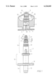
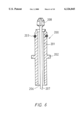
- FIG. 1 schematically, partly in cross-section, the parts of a preferred embodiment for the connector assembly according to the invention
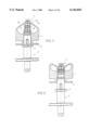
- FIG. 2 schematically, the connector assembly of FIG. 1, with the plug closing off the bore in the female part and the male part inserted in the female part and the plug;
- FIG. 3 schematically, the connector assembly of FIG. 1, with the plug free from the bore in the female part and borne by the male part;
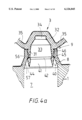
- FIGS. 4a-e in cross-section, different successive stages of making a fluid connection with the connector assembly of FIG. 1;
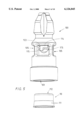
- FIG. 5 in perspective, a preferred embodiment of the male part of the connector assembly according to the second aspect of the invention.
- FIG. 6 in cross-section, a variant of the male part of the connector assembly according to the invention.
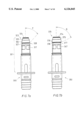
- FIG. 7a in side view, another embodiment of the male part of the connector assembly according to the invention, in which the male part is suitable for connecting with and disconnecting from the plug multiple times;
- FIG. 7b a variant of the male part of FIG. 7a, in which the male part can be connected with the plug only once to form a permanent connectio;
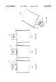
- FIGS. 8a-d a variant of the connector assembly according to the invention.
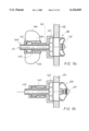
- FIGS. 9a and 9b in longitudinal section, a subsequent embodiment of the connector assembly according to the invention.
- FIGS. 10a and 10b in longitudinal section, a subsequent embodiment of the connector assembly according to the invention.
- the connector assembly shown is intended for providing a fluid connection for fluids, gases, liquid substances, such as soap, cosmetic creams, soft drink syrup, etcetera.
- the connector assembly is also suitable for powders, in particular fine powders, having suitable flow properties to flow through such a connector, such as coffee powder and the like or toner powder for printers and copiers, etcetera.
- the female part of the connector assembly could then be part of a cartridge containing powder, whereas the male part is of the copier, printer or coffee machine.
- the connector assembly in fact comprises three components: a female part 1, a male part 2 which can be connected to it, and a plug 3.
- the female part 1 and the plug 3 are preferably manufactured as a unitary plastic object in a suitable mould by means of injection moulding.
- the male part 2 may also be manufactured as a plastic injection moulding product, but the male part 2 may also be made of metal, for instance stainless steel.
- the female part 1 has a body with a front end 5 and a rear end 6, with an axial and essentially cylindrical bore 7 extending through the body from the insert opening 4 for the male part 2 at the front end 5; this bore 7 is open at both ends.
- the edge at the transition from the front end 5 to the bore 7 is bevelled.
- the bore 7 is bounded by a ring wall 8 protruding from the body.
- the inner surface of the ring wall 8 forms a seat 9 for the plug 3 extending around the bore 7; this plug 3 serves for closing of the bore 7.
- the body of the female part 1 is especially suited for being welded or glued into the wall or a seam of a flexible plastic bag.
- the body of the female part 1 can also be laid out to be placed in the neck of a bottle or similar container, or in a stable ring-shaped holder fitted to a flexible bag.
- the latter design is known notably for so-called "bag-in-box" systems.
- the male part 2 has a tubular end piece 10 fitting into the bore 7 of the female part 1.
- a radially protruding stop ridge 11 of the male part 2 rests against the front end 5 of the female part 1.
- the male part 2 further comprises a tubular part 12, connected to the endpiece 10, with a ring-shaped projection 13 to facilitate handling of the male part 2.
- a hose coupling part 14 Connected to the tubular part 12 is a hose coupling part 14, enabling the male part 2 to be connected to a hose (not shown).
- the male part 2 contains an internal axial passage 15, indicated by dotted lines, for the fluid.
- the axial passage 15 is open at the end of the hose connection part 14 and is blind at the other end, which means that the passage 15 does not extend to the tip of the end piece 10 but stops at some distance of this.
- Within the male part 2 a number, in this case four, of cross passages 17 have been formed, which connect the axial passage 15 near its blind end with the perimeter of the male part 2.
- the male part 2 further comprises at its perimeter two diametrically opposed blocking devices 19, which extend parallel with the longitudinal axis of the male part 2 from the stop ridge 11 in the direction of the tip of the end piece 10.
- the female part 1 is provided with two diametrically opposed grooves 20, extending in axial direction along the bore 7, which serve to receive the blocking devices 19 when the male part 2 is inserted into the bore 7.
- the cooperation between the blocking devices 19 and the grooves 20 prevents the male part 2 from turning with respect to the female part 1 before the male element 2 is connected to the plug 3, as will be explained further on.
- the blocking devices 19 and the grooves 20 make it easier to insert the male part 2 into the bore 7.
- it is possible to obtain a kind of key so that a unique combination of a female part 1 and a male part 2 is obtained and a connection between non-matching male and female parts is prevented.
- the end piece 10 is further provided with a ring-shaped groove 22 to receive a sealing ring (not shown here to avoid confusion), which establishes the seal between the male part 2 and the female part 1 and also contributes to holding the male part 2 in the bore 7.
- the groove 22 is located in the area between the cross passages 17 and the stop ridge 11.
- a ridge can be provided at the outside of the male part 2.
- the tip of the end piece 10 of the male part 2 is constructed as an essentially conical head 23 with at its extremity an essentially cylindrical projection 24.
- the head 23 first has a locating surface 25, coned towards the outside, and contiguous with this a gripping surface 26, outwardly tapered at a small cone angle towards the outside.
- Contiguous with the gripping surface 26 is a shoulder surface 27, tapered towards the inside, which ends at the bottom of a recess, formed by the circumferential groove 28, between the head 23 and the part of the male part 2 that is provided with cross passages 17.
- the head 23 is provided with two diametrically opposed grooves 29, which extend from the tip of the end piece 10 to behind the head 23 and end in the groove-shaped recess 28.
- the plug 3 has a ring wall 31 and an end wall 32, which together enclose a cavity 33 in plug 3 which is open towards the insert opening 4; this cavity 33 is intended to receive the head 23 of the male part 2.
- the end wall 32 forms a cylindrical recess 34, whose diameter is adjusted to the diameter of the cylindrical projection 24 of the head 23. This complementary shape ensures that the plug 3 will remain seated in the correct position on the head 23 and will not tilt.
- the inner surface of the ring wall 31 is made complementary to the head 23 of the male part 2.
- the grooves 29 allow any substance present in the cavity 33 to escape via the grooves 29 when the head 23 enters the cavity 33.
- the plug 3 is connected with the body of the female part 1 by two flexible bodies 35.
- the bodies 35 ensure that the plug 3 cannot be separated from the female part 1. Furthermore, the length of the bodies 35 is such that when the connector assembly is in the position shown in FIG. 1, the male part 2 can connect with the plug 3.
- the plug 3 has a radially expandable and compressible ring-shaped collar 40, which forms a whole with plug 3.
- the collar 40 has an interior surface 41, tapered from its free edge towards the inside, which connects to a shoulder surface 42 coned towards the outside, which in turn connects to the inside of ring wall 31.
- the collar 40 further has an exterior surface 44, tapered from its free edge towards the outside, which connects to a ring-shaped hooking surface 45 which is coned towards the inside, which in turn connects to the outer surface of ring wall 31.
- the plug 3 further has a sealing rim 46 located around the outside of the ring wall 31 and protruding towards the outside.
- the plug 3 also has an outward protruding ring-shaped stop surface 47 at the side of the sealing rim 46 which faces away from the collar 40.
- the ring wall 8 has an axial end face 50, against which the stop surface 47 of the plug 3 rests when the plug 3 is in its seat 9.
- the bore 7 has a first part with such a diameter that the male part 2 can be inserted in it with a light drive fit.
- the first part changes to a second part of bore 7 with a slightly smaller diameter.
- a shallow circumferential groove 53 in the bore 7 is located so that the sealing ring (not shown) of the male part 2, inserted fully into the female part 1, engages partly in this groove, so that on the one hand a reliable seal is obtained and on the other hand a kind of snap connection is obtained.
- the ring wall 8 has (see FIG. 4a), viewed from the end face 50 in the direction of the insert opening 4, a cylindrical sealing surface 54, with an inner diameter that is slightly smaller than the outer diameter of the sealing rim 46 of the plug 3. Consequently the plug 3 with its sealing rim 46 will fit tightly in the ring wall 8, thus establishing a radial seal.
- an inward tapered transition surface 55 connects to the sealing surface 54; this transition surface 55 in its turn passes into an outward tapered shoulder surface 56 of the bore 7.
- a transition surface 57 Connected to this conical shoulder surface 56 is a transition surface 57, tapered outwards at a smaller angle, which connects to the second cylindrical part of the bore 7.
- FIGS. 4a-4e On the basis of FIGS. 4a-4e the operation of the connector assembly will be explained. It should be noted that for the sake of clarity not all of the reference numbers mentioned in the description have been given; in these cases the reference numbers can be found in one of the other FIGS. 4a-e.
- FIG. 4a shows in which way the plug 3, located in its seat, closes off the bore 7.
- the plug 3 rests with its stop surface 47 against the end face 50 of the ring wall 8 and presses the sealing rim 46 into the ring wall 8.
- the collar 40 is in its first position and the ring-shaped smooth hooking surface 45 of the plug 3 rests at an elastic prestress against the shoulder surface 56 of the bore 7.
- the contact of the stop surface 47 against the end face 50 provides a second seal of the bore 7.
- a space is present whose size in a radial sense increases from the shoulder 56 towards the insert opening 4.
- this transition rim viewed in the insert direction, lies axially in front of the shoulder surface 56 of the bore 7 when the plug 3 is in the seat 9.
- the collar 40 is subjected to an outward bending moment with respect to the thin connection of the collar 40 to the ring wall 31.
- the surface 57 of the bore 7 of the shoulder surface 56 slopes outward, around the collar 40 of the plug 3 which is located in its seat a space is present of such dimensions that collar 40 can expand radially without significant resistance of the female part 1 to allow the head 23 to be inserted in the cavity 33.
- the force required for the expansion of the collar 40 is therefore determined in particular by the rigidity of the collar 40 itself.
- FIG. 4c shows the situation when the head 23 of the male part 2 is located entirely in the cavity 33 of the plug 3.
- the cylindrical projection 24 of the head 23 fits in the recess 34.
- the collar 40 has sprung back elastically from its second position as shown in FIG. 4b to a third position.
- This third position is slightly further outward than the first position shown in FIG. 4a, so the shoulder surface 42 of the plug 3 lies under prestress against the shoulder surface 27 of the head 23 and thus holds the head 23 in the plug 3 in a reliable way.
- the shoulder surface 56 of the bore 7 exerts a reaction force on the hooking surface 45 of the collar 40, which leads to an inward bending moment on the collar 40, again with respect to the thin connection of the collar 40 to the ring wall 31.
- the collar 40 can easily be compressed radially and so the diameter of the collar 40 decreases. Consequently the hooking surface 45 becomes more parallel to the axis of the male part 2, so that the force exerted via the hooking surface 45 on the ring wall 8 causes the ring wall 8 to expand radially to a greater degree.
- the collar 40 can pass the smallest diameter of the shoulder surface 56 of the bore 7 in a fourth position, pressed further inward, thus coming in the position shown in FIG. 4d.
- the conical exterior surface 44 of the collar 40 enters the part of the bore 7 which is bounded by the sealing surface 54.
- the collar 40 is compressed radially, back to its fourth position, so that the force which is required to pull the head 23 from the plug 3 has become so much greater that first the plug 3 is pulled completely from its seat 9.
- the collar 40 subsequently passes the transition edge between the transition surface 55 and the shoulder surface 56 of the bore 7.
- the shoulder surface 27 of the head 23 exerts an outward bending moment on the collar 40; at that moment this collar 40 can easily expand again radially to its second position. As a result the head 23 can then be pulled from the plug 3 with a small force and subsequently the collar 40 springs back to its first position.
- the connector assembly according to the invention it is possible to dimension as desired the axial force required during the different phases of connecting and disconnecting the male and female parts. For instance, it is possible to keep the axial force essentially constant during all the phases described above. In particular it is possible with the connector assembly described here that the axial force required to connect the male part 2 with the plug 3 is essentially equal to the axial force required to push the plug 3 subsequently from the bore 7.
- the cross section of the collar 40 is not uniform along its entire perimeter, but is built up from segments which are separated from each other by axial dividing seams or are connected to each other by thin bridging parts designed as thin film.
- the collar 40 may also be replaced by several discrete hooking fingers around the perimeter of the plug 3.
- FIG. 5 shows one end, to be inserted into a female part, of a preferred embodiment of the male part 100 according to the second aspect of the invention.
- the male part 100 is very similar to the male part 2 described earlier, to which reference is made here, and can also be used in combination with the female part 1. An important difference is that the male part 100 is provided with an internal closing part, as will be explained below.
- the male part 100 has an internal axial passage 101 for a liquid, which is open on one end and is made blind at the tip of the insert end, and ends at an end wall 103.
- Several cross passages 105 have been provided, in this case four around the perimeter of the male part 100, each extending from the outer surface of the male part 100 to an outlet in the axial passage 101.
- a closing body 110 is fitted, which is shown separately in FIG. 5.
- the closing body 110 is essentially cup-shaped with a flexible ring wall 111, which is intended to lie under prestress against the interior wall of the axial passage 101, thereby closing off the outlets of the cross passages 105.
- the flexible ring wall 111 can bend radially inward so as to provide a passage for the liquid.
- a suitable design of the closing body 110 makes it possible to choose the prestress with which the ring wall 111 presses against the axial passage 101 and the rigidity of the ring wall 111 in such a way that a passage is only created when there is a certain pressure difference between the inside and the outside of the ring wall 111.
- the closing body 110 acts as a non-return valve.
- the closing body 110 has a cross wall 112, transverse to the flexible ring wall 111, with a central opening in it (not discernible here).
- the closing body 110 can be removed from the male part 100 for cleaning or changing.
- Moulded to the end wall 103 of the axial passage 101 is a shank 114 with two diametrically opposed radial projections 115 at some distance from the end wall 103.
- the shank 114 protrudes through the opening in the cross wall 112 of the closing body 110, so that the projections 115 hook behind the cross wall 112 of the closing body 110.
- the closing body 110 is preferably an undivided object of a suitable rubber, silicone or elastomer and can be manufactured by injection moulding. As the closing body covers the outlets of the cross passages 105 the chance of undesired contamination of the axial passage, or a substance present in this, is minimal. It is also possible with this closing body 110 to prevent the presence of undesired air when making the connection with a suitable female part.
- FIG. 6 shows a male part 200, which is suitable for application in combination with the connector assembly described in FIGS. 1, 2, 3 and 4a-4e, namely for filling of a container which is provided with the female part 1 or similar.
- the male part 200 comprises a tubular body 201 with a stop ridge 202, which in the fully inserted position rests against the female part. Furthermore, an O-ring 203 can be recognised which accomplishes the seal between the male part 200 and the female part.
- the tubular body 202 has an internal axial passage 206, which is open at the insert end. In this axial passage 206 a rod 207 is provided which can move back and forth, with a head 208 which is in essence similar to the head 23 of the male part 2.
- the male part 200 is inserted into the female part 1.
- the plug 3 is already out of its seat 9 or that the plug 3 is still in its seat 9. This will depend notably on the production method chosen for the assembly of plug 3 and the female part 1.
- the rod 207 By operating the rod 207 the plug 3 can be pushed from the bore 7, if necessary, and the container can be filled through the female part 1. After filling the plug 3 is pulled into the seat 9 with the rod 207, thus closing the container.
- the male part 200 shown in FIG. 6 can also be used to first create a vacuum in the container and subsequently pull the plug 3 into the female part 1. The closure of the bore 7 thus obtained is such that the vacuum is maintained for a long time.
- a similar male part 200 can be used, if necessary under sterile conditions, to push the plug 3 from its seat 9 again and the container can be filled through the passage 206, without air entering the container.
- the plug 3 is pulled back into its seat 9 using the same male part 200 as the one with which the container was filled.
- the head 208 can be pulled against the body 201 to obtain a seal between these parts, so that no air and/or contamination can enter the passage 206.
- FIG. 7a shows a male part 300 with an insert part 301, which is essentially identical to the part 10 of the male part 2 shown in FIG. 1.
- the insert part 301 is suitable for insertion into the bore of a female part, not shown, which is essentially identical to the female part 1 shown in FIG. 1.
- the male part 300 has a head 323 with a cylindrical projection 324 at its end, a locating surface 325 and a conical gripping surface 326.
- the gripping surface 326 passes, via a shoulder surface 327 sloping inward at an angle F with respect to the longitudinal axis, into a recess 328 located behind the head 323.
- the head 323 of the male part 300 fits in the corresponding cavity of the plug of the female part in such a way that it can be inserted into and pulled out of the cavity multiple times.
- FIG. 7b shows, at the same scale as FIG. 7a, a male part 350 which is a variant of the male part 300.
- the male part 350 can be connected with exactly the same female part and corresponding plug as the male part 300.
- the difference between the male parts 300 and 350 consists of the design of the head 373, which is such that this head 373 cannot leave the cavity of the plug, unless a destructive force is used.
- the head 373 has, similar to the head 323, a projection 374, a locating surface 375, a conical gripping surface 376, anda shoulder surface 377, which connects to a recess 378.
- the difference between the head 323 and the head 373 is that the diameter of the head 373 is larger, so that the ring wall of the plug of the female part is expanded to a substantial degree when the head 373 is located in the cavity of the plug.
- the largest diameter of the head 373 is larger than the diameter of the part provided with the openings 367
- the largest diameter of the head 323 is smaller than the diameter of the part provided with the openings 317, the latter diameter being equal to the diameter of the part provided with the openings 367.
- Owing to the oversized diameter of the head 323 the latter is clamped with a high radial force in the cavity of the plug, whereby the collar of this plug is not pressed radially outward and this collar thus keeps the head 373 firmly in the cavity.
- the shoulder surface makes an angle G with the longitudinal axis which is substantially larger than the angle F in FIG.
- the head is provided with several corrugations protruding outward, of which the sides facing towards the collar of the plug are each almost perpendicular to the longitudinal axis of the male part.
- FIGS. 8a-d show a container 400, which is provided with the female part 1 (not discernible here) or a similar female part, and a variant of the male part 350 shown in FIG. 7b, designed in the form of a closable tap 402.
- FIG. 8a a removable band 403 can be seen, which keeps the male part 402 at some distance of the female part, in such away that the male part 402 is connected with the plug 3 of the female part 1, but the plug 3 is still in its seat 9 (see FIGS. 2 and 4).
- the tap 402 can be pushed towards the female part 1, causing the plug 3 to come out of its seat.
- the tap 402 itself has an additional and manually operable closing body 404, in this case a hinging cover, which is shown in the opened position in FIG. 8d.
- the plug 3 is pulled back into its seat 9 and the container 400 is hermetically sealed. Owing to the design of the male part 402 as explained on the basis of FIG. 7b, the tap 402 cannot be removed from the container 400.
- FIGS. 9a and 9b show an embodiment of the connector assembly according to the invention as a closable tap.
- These figures show a female part 430 with a plug 431, which are essentially the same as the female part 1 and the plug 3 shown in FIG. 1.
- the female part 430 is mounted in a wall 432 of a container of which only a part is shown.
- a male part 440 is shown, of which the part inserted in the bore of the female part 430 is essentially the same as the corresponding part of the male part 350 in FIG. 7b.
- the head of the male part 440 is therefore permanently connected with the plug 431.
- the part inserted in the bore connects to a tubular part 441 with an axial passage, which can slide in a corresponding bore of the outer guide 442.
- the outer guide 442 is attached, in this case with snap fingers 443, to the female part 430.
- the outer guide 442 is provided with projections 444 forming an exterior screw thread.
- a bush 445 provided with interior screwthread, which meshes with the exterior screw thread of the outer guide 442.
- the bush 445 is designed to be gripped by the users hand and to be turned; for this purpose two handle projections 446 are moulded on. Moulded onto the tubular part 441 of the male part 440 is a driver 447, which meshes with the bush 445.
- the male part 440 By turning the bush 445 the male part 440 can be moved between a closed position, in which the plug 431 closes off the bore in the female part 430 (FIG. 9a) and an opened position, in which the male part 440 is inserted further into the bore and the plug 431 has been pushed from the bore, so that a fluid connection is provided.
- FIGS. 10a and 10b show a lock part 500 with which a variant of the male part 2 of FIG. 1, indicated by reference number 501, can be fixed to the female part 1.
- the malepart 501 in fact comprises the part of the male part 2 which is indicated in FIG. 1 by reference number 10 and an adjoining part 502, which fits into the bore 503 of the lock part 500.
- the lock part 500 and the male part 501 are provided with coupling devices, not shown here, for establishing a detachable connection between the two parts. For instance, a bayonet coupling or a snap connection may be provided.
- the lock part 500 is provided with one or more, preferably two diametrically opposed, tilting grippers 505.
- each of the tilting grippers 505 is mounted to the lock part 500 in such a way that it can tilt around a tilting axis 504 which is placed transversal to the longitudinal axis of the bore 503.
- each tilting gripper 505 is provided with a gripping notch 506 or similar device, with which the tilting gripper 505 can hook behind a flanged edge moulded to the female part 1, or in a corresponding recess.
- each tilting gripper 505 has a part that extends from the tilting axis 504 in the direction away from the gripping notch 506.
- the tilting axes 504 are made of plastic and keep the tilting grippers 505 in a position in which the gripping notches 506 are close to each other.
- the bevelled gripping notches 506 move away from each other and lock behind an edge of the female part.
- the tilting grippers 505 will tilt and the gripping notches 506 will move apart, so the male part 501 can be removed from the female part 1.
- a ring 509 behind the transversal legs 508 is positioned in such a way that these transversal 508 legs make contact with this ring 509 when the tilting grippers 505 are compressed, see FIG. 10b.
- the ring 509 gives additional support to the transversal legs 508.
- the lock part 500 has a connection part 510 for a hose or other part.
- the male part consists of multiple connectable parts, with the part that is to be inserted into the bore of the female part being a separate part.
- This part can then be joined to a connecting part adjusted to the envisaged application, preferably disconnectable, for instance with a bayonet coupling or a snap connection.
- the connecting part can be straight or bent at right angles, or designed as the lock element 500 in FIGS. 10a and 10b.
Applications Claiming Priority (3)
| Application Number | Priority Date | Filing Date | Title |
|---|---|---|---|
| NL1006636 | 1997-07-21 | ||
| NL1006636A NL1006636C2 (nl) | 1997-07-21 | 1997-07-21 | Verbindingssamenstel voor een fluïdumverbinding. |
| PCT/NL1998/000385 WO1999005446A1 (fr) | 1997-07-21 | 1998-07-07 | Ensemble raccord pour raccord a liquide |
Related Parent Applications (1)
| Application Number | Title | Priority Date | Filing Date |
|---|---|---|---|
| PCT/NL1998/000385 Continuation WO1999005446A1 (fr) | 1997-07-21 | 1998-07-07 | Ensemble raccord pour raccord a liquide |
Publications (1)
| Publication Number | Publication Date |
|---|---|
| US6126045A true US6126045A (en) | 2000-10-03 |
Family
ID=19765388
Family Applications (1)
| Application Number | Title | Priority Date | Filing Date |
|---|---|---|---|
| US09/480,919 Expired - Lifetime US6126045A (en) | 1997-07-21 | 2000-01-11 | Connector assembly for a fluid connection |
Country Status (19)
| Country | Link |
|---|---|
| US (1) | US6126045A (fr) |
| EP (2) | EP0998644B1 (fr) |
| JP (2) | JP3411270B2 (fr) |
| KR (1) | KR20010021976A (fr) |
| CN (1) | CN1100958C (fr) |
| AT (1) | ATE225918T1 (fr) |
| AU (1) | AU749987B2 (fr) |
| BR (1) | BR9811517A (fr) |
| CA (1) | CA2296605C (fr) |
| DE (1) | DE69808639T2 (fr) |
| DK (1) | DK0998644T3 (fr) |
| ES (1) | ES2187039T3 (fr) |
| ID (1) | ID24849A (fr) |
| NL (1) | NL1006636C2 (fr) |
| PL (1) | PL188259B1 (fr) |
| PT (1) | PT998644E (fr) |
| RU (1) | RU2198121C2 (fr) |
| TR (1) | TR200000138T2 (fr) |
| WO (1) | WO1999005446A1 (fr) |
Cited By (35)
| Publication number | Priority date | Publication date | Assignee | Title |
|---|---|---|---|---|
| US6354473B1 (en) * | 1998-08-05 | 2002-03-12 | Euro Maintenance Lease Produktie B.V. | Closing valve for a container |
| US20030121936A1 (en) * | 2001-10-04 | 2003-07-03 | De Laforcade Vincent | Device for dispensing separately packaged products together |
| US20040001655A1 (en) * | 2002-07-01 | 2004-01-01 | Proicou George C. | Drug containment system |
| US20040031535A1 (en) * | 2002-08-14 | 2004-02-19 | Russell Scott T. | Stackable product packaging |
| US20050051572A1 (en) * | 2003-09-05 | 2005-03-10 | Vogel James E. | Blow fill sealed container with twist off top operated by overcap and method of forming the same |
| US20050073162A1 (en) * | 2003-10-03 | 2005-04-07 | Handberg Robert C. | Bag carrying handle |
| US6921113B1 (en) * | 1999-05-10 | 2005-07-26 | Casparus Pds B.V. | Connector assembly and method of manufacture |
| US20060071006A1 (en) * | 2004-10-04 | 2006-04-06 | Leahy/Ifp | Hydration system |
| US20060144875A1 (en) * | 2004-12-29 | 2006-07-06 | Etesse Patrick J | Flexible container containing a liquid product, and a process for making a liquid-filled, flexible container |
| US20060261099A1 (en) * | 2004-09-13 | 2006-11-23 | Diego Nini | Delivering tap and process for manufacturing such tap |
| US20060278656A1 (en) * | 2005-06-14 | 2006-12-14 | Scott Ross | Spout handle and nozzle assembly |
| US20070127854A1 (en) * | 2005-12-05 | 2007-06-07 | Smith Mark A | Form fill and seal container |
| US20070205216A1 (en) * | 2006-03-01 | 2007-09-06 | Smith Mark A | Puncturable cap and piercer |
| US20100163585A1 (en) * | 2007-02-21 | 2010-07-01 | Johnsondiversey, Inc. | Dispensing closure |
| US7806300B1 (en) * | 2004-04-09 | 2010-10-05 | Blackhawk Industries Product Group Unlimited Llc | Hydration system |
| US20110052102A1 (en) * | 2005-09-19 | 2011-03-03 | Sven Stiers | Drain connector for substance processing receptacle |
| US20110056983A1 (en) * | 2008-05-12 | 2011-03-10 | Hewlett-Packard Development Company Lp | Bag-in-box container including a pre-positioned, secured dispensing spout |
| CN102103033A (zh) * | 2010-12-14 | 2011-06-22 | 中国包装科研测试中心 | 钢桶气密性测试仪 |
| US20120261441A1 (en) * | 2009-12-16 | 2012-10-18 | Ipn Ip B.V. | Fluid dose-measuring device |
| US20150028065A1 (en) * | 2013-07-03 | 2015-01-29 | Scholle Corporation | Connector assembly for a self sealing fitment |
| NL2011347C2 (en) * | 2013-08-28 | 2015-03-03 | Ipn Ip Bv | Fluid dose-measuring device. |
| CN104905631A (zh) * | 2008-05-20 | 2015-09-16 | 格里南实业公司 | 流体输送组件及流体输送方法 |
| US20150266714A1 (en) * | 2012-10-22 | 2015-09-24 | Kabushiki Kaisha Cosmo Life | Water dispenser |
| US9173521B2 (en) | 2011-12-02 | 2015-11-03 | Fbd Partnership, Lp | Food and beverage dispenser with cleaning system |
| CN106185776A (zh) * | 2010-01-19 | 2016-12-07 | 格里南实业公司 | 流体输送组件及流体输送方法 |
| US9827582B2 (en) | 2015-11-04 | 2017-11-28 | Ecolab Usa Inc. | Refillable dispensing systems and components |
| US20180184839A1 (en) * | 2015-08-07 | 2018-07-05 | Franke Kaffeemaschinen Ag | Cleaning agent container |
| WO2019010393A1 (fr) | 2017-07-07 | 2019-01-10 | Gojo Industries, Inc. | Distributeurs rechargeables à réservoirs et récipients de recharge conçus pour un transfert de fluide et d'air entre ceux-ci |
| US10526194B2 (en) * | 2016-08-18 | 2020-01-07 | Scholle Ipn Ip Bv | System for transporting and storing a liquid and for transporting said liquid from the container to a destination outside of the container |
| US10961025B2 (en) * | 2016-12-08 | 2021-03-30 | Fujimori Kogyo Co., Ltd. | Pouring spout of container |
| US11014801B2 (en) | 2017-11-10 | 2021-05-25 | Pentair Flow Technologies, Llc | Coupler for use in a closed transfer system |
| US20220002038A1 (en) * | 2018-10-30 | 2022-01-06 | Fujimori Kogyo Co., Ltd. | Pouring spout |
| US11220379B2 (en) | 2019-05-23 | 2022-01-11 | Ecolab Usa Inc. | Dispensing system |
| US20220009688A1 (en) * | 2018-10-30 | 2022-01-13 | Fujimori Kogyo Co., Ltd. | Pouring spout |
| US20220281668A1 (en) * | 2021-03-03 | 2022-09-08 | Scholle Ipn Corporation | Dispensing system for a flexible bag, flexible bag assembly |
Families Citing this family (27)
| Publication number | Priority date | Publication date | Assignee | Title |
|---|---|---|---|---|
| NL1011960C2 (nl) | 1999-05-04 | 2000-11-07 | Itsac Nv | Houder, in het bijzonder een flexibele houder, met een afsluitbare opening en werkwijze voor het vullen van een dergelijke houder. |
| EP1206386A4 (fr) * | 1999-07-23 | 2002-10-30 | Scholle Corp | Ensemble de raccords pour ecoulement fluide avec mouvement rotatif pour vissage et devissage |
| US6644367B1 (en) | 1999-07-23 | 2003-11-11 | Scholle Corporation | Connector assembly for fluid flow with rotary motion for connection and disconnection |
| NL1016292C2 (nl) * | 2000-09-28 | 2002-04-02 | Itsac Nv | Zak alsmede een afgiftesysteem omvattende een dergelijke zak en werkwijzen voor de vervaardiging en het vullen van een dergelijke zak. |
| JP4665305B2 (ja) * | 2000-11-21 | 2011-04-06 | 株式会社パックプラス | 容器用蓋装置 |
| NL1019138C2 (nl) | 2001-10-08 | 2003-04-09 | Itsac Nv | Samenstel voor een afsluitbare fluïdumverbinding. |
| JP4269098B2 (ja) * | 2002-09-02 | 2009-05-27 | 株式会社昭和丸筒 | 連結システム、連結システム用雄部材及び閉栓部材 |
| NL1023568C2 (nl) | 2003-05-28 | 2004-11-30 | Akzo Nobel Nv | Systeem voor het afgeven van een substantie. |
| JP2005152083A (ja) * | 2003-11-21 | 2005-06-16 | Asahi Kasei Chemicals Corp | 身体洗浄料を供給する方法 |
| DE102004033205A1 (de) * | 2004-07-09 | 2006-02-09 | Fresenius Kabi Deutschland Gmbh | Steriler Port |
| EP1959009A4 (fr) | 2005-12-06 | 2010-04-28 | Kyowa Hakko Kirin Co Ltd | Anticorps anti-perp génétiquement recombiné |
| BRPI0715001A2 (pt) * | 2006-09-08 | 2013-07-23 | Scholle Corp | melo de regulaÇço de transparÊncia de Água para um dispensador de Água, dispensador de Água e conteiner removÍvel de Água |
| US8109236B2 (en) * | 2007-04-05 | 2012-02-07 | Sumitomo Corporation Of America | Fluid delivery assembly |
| JP5162154B2 (ja) * | 2007-04-20 | 2013-03-13 | 株式会社パックプラス | 流体容器用コネクタユニット、流体容器用コネクタおよび流体容器 |
| JP4982263B2 (ja) * | 2007-06-18 | 2012-07-25 | 株式会社パックプラス | ディスペンサ |
| US7974558B2 (en) | 2007-06-25 | 2011-07-05 | Samsung Electronics Co., Ltd. | Toner cartridge locking apparatus, image forming apparatus having the same, toner cartridge, and mounting and dismounting method for a toner cartridge |
| JP4715855B2 (ja) * | 2008-03-24 | 2011-07-06 | 株式会社パックプラス | 包装体およびその製造方法 |
| JP5908502B2 (ja) | 2011-02-15 | 2016-04-26 | シーダブリューエス−ボコ サプライ アクチェンゲゼルシャフト | 液体容器用のバルブ |
| CN102267681A (zh) * | 2011-07-25 | 2011-12-07 | 陈东浩 | 饮料袋限流开关装置 |
| CZ307182B6 (cs) | 2011-12-30 | 2018-02-28 | Grinon Industries | Souprava pro přečerpávání tekutin a metody přečerpávání tekutin |
| JP6616652B2 (ja) * | 2015-10-21 | 2019-12-04 | 株式会社パックプラス | 連結システム |
| CN105423053A (zh) * | 2015-11-19 | 2016-03-23 | 马玉荣 | 一种下水管道塞帽 |
| NL2017638B1 (en) | 2016-10-19 | 2018-04-26 | Gab Eng & Development B V | A container closure |
| WO2019237162A1 (fr) * | 2018-06-12 | 2019-12-19 | Eric Zembrod | Dispositif de distribution sans entrée d'air pour embouts applicateurs d'emballages souples divers |
| NL2023592B1 (en) | 2019-07-30 | 2021-02-23 | Scholle Ipn Ip Bv | Container assembly and method for preparing such a container assembly |
| FR3108316B1 (fr) | 2020-03-23 | 2022-04-01 | United Caps France | Bouchon de fermeture pour recipient a col filete et convenant a une utilisation dans un systeme de transfert ferme |
| JP6925666B1 (ja) * | 2020-05-12 | 2021-08-25 | 株式会社パックプラス | 連結システム |
Citations (9)
| Publication number | Priority date | Publication date | Assignee | Title |
|---|---|---|---|---|
| US3783590A (en) * | 1970-07-09 | 1974-01-08 | A Allen | Filter-silencer for pneumatic devices |
| US4171007A (en) * | 1976-03-05 | 1979-10-16 | Societe Anonyme: La Telemecanique Electrique | Unidirectional flow limiter |
| US4301590A (en) * | 1979-03-12 | 1981-11-24 | Baxter Travenol Laboratories, Inc. | Method of assembling an injection site to a support tube |
| US4375864A (en) * | 1980-07-21 | 1983-03-08 | Scholle Corporation | Container for holding and dispensing fluid |
| US5095962A (en) * | 1990-08-09 | 1992-03-17 | Scholle Corporation | Beverage dispenser coupling |
| WO1994026611A1 (fr) * | 1993-05-06 | 1994-11-24 | Taplast S.R.L. | Bouchon en matiere plastique pour distribuer des liquides |
| US5370270A (en) * | 1991-10-08 | 1994-12-06 | Portola Packaging, Inc. | Non-spill bottle cap used with water dispensers |
| US5467806A (en) * | 1994-05-10 | 1995-11-21 | Scholle Corporation | Two-part coupling structure having cooperating parts effecting fluid flow upon connection an mutual resealing upon disconnection |
| US5632303A (en) * | 1993-07-08 | 1997-05-27 | Wcm Industries, Inc. | Wall water hydrant having backflow and back siphonage preventor |
Family Cites Families (2)
| Publication number | Priority date | Publication date | Assignee | Title |
|---|---|---|---|---|
| US3871422A (en) * | 1973-02-14 | 1975-03-18 | Automatic Helium Balloon Syste | Dual balloon valve |
| US4445551A (en) * | 1981-11-09 | 1984-05-01 | Bond Curtis J | Quick-disconnect coupling and valve assembly |
-
1997
- 1997-07-21 NL NL1006636A patent/NL1006636C2/nl not_active IP Right Cessation
-
1998
- 1998-07-07 JP JP2000504395A patent/JP3411270B2/ja not_active Expired - Fee Related
- 1998-07-07 AU AU82459/98A patent/AU749987B2/en not_active Ceased
- 1998-07-07 ID IDW20000108A patent/ID24849A/id unknown
- 1998-07-07 CN CN98807143A patent/CN1100958C/zh not_active Expired - Lifetime
- 1998-07-07 DE DE69808639T patent/DE69808639T2/de not_active Expired - Lifetime
- 1998-07-07 PT PT98932624T patent/PT998644E/pt unknown
- 1998-07-07 RU RU2000101314/06A patent/RU2198121C2/ru not_active IP Right Cessation
- 1998-07-07 CA CA002296605A patent/CA2296605C/fr not_active Expired - Lifetime
- 1998-07-07 EP EP98932624A patent/EP0998644B1/fr not_active Expired - Lifetime
- 1998-07-07 AT AT98932624T patent/ATE225918T1/de not_active IP Right Cessation
- 1998-07-07 TR TR2000/00138T patent/TR200000138T2/xx unknown
- 1998-07-07 KR KR1020007000541A patent/KR20010021976A/ko not_active Application Discontinuation
- 1998-07-07 BR BR9811517-0A patent/BR9811517A/pt not_active IP Right Cessation
- 1998-07-07 ES ES98932624T patent/ES2187039T3/es not_active Expired - Lifetime
- 1998-07-07 DK DK98932624T patent/DK0998644T3/da active
- 1998-07-07 WO PCT/NL1998/000385 patent/WO1999005446A1/fr not_active Application Discontinuation
- 1998-07-07 PL PL98338417A patent/PL188259B1/pl not_active IP Right Cessation
- 1998-07-07 EP EP02076283A patent/EP1233228A3/fr not_active Withdrawn
-
2000
- 2000-01-11 US US09/480,919 patent/US6126045A/en not_active Expired - Lifetime
-
2003
- 2003-01-20 JP JP2003010913A patent/JP4327467B2/ja not_active Expired - Fee Related
Patent Citations (9)
| Publication number | Priority date | Publication date | Assignee | Title |
|---|---|---|---|---|
| US3783590A (en) * | 1970-07-09 | 1974-01-08 | A Allen | Filter-silencer for pneumatic devices |
| US4171007A (en) * | 1976-03-05 | 1979-10-16 | Societe Anonyme: La Telemecanique Electrique | Unidirectional flow limiter |
| US4301590A (en) * | 1979-03-12 | 1981-11-24 | Baxter Travenol Laboratories, Inc. | Method of assembling an injection site to a support tube |
| US4375864A (en) * | 1980-07-21 | 1983-03-08 | Scholle Corporation | Container for holding and dispensing fluid |
| US5095962A (en) * | 1990-08-09 | 1992-03-17 | Scholle Corporation | Beverage dispenser coupling |
| US5370270A (en) * | 1991-10-08 | 1994-12-06 | Portola Packaging, Inc. | Non-spill bottle cap used with water dispensers |
| WO1994026611A1 (fr) * | 1993-05-06 | 1994-11-24 | Taplast S.R.L. | Bouchon en matiere plastique pour distribuer des liquides |
| US5632303A (en) * | 1993-07-08 | 1997-05-27 | Wcm Industries, Inc. | Wall water hydrant having backflow and back siphonage preventor |
| US5467806A (en) * | 1994-05-10 | 1995-11-21 | Scholle Corporation | Two-part coupling structure having cooperating parts effecting fluid flow upon connection an mutual resealing upon disconnection |
Cited By (64)
| Publication number | Priority date | Publication date | Assignee | Title |
|---|---|---|---|---|
| US6354473B1 (en) * | 1998-08-05 | 2002-03-12 | Euro Maintenance Lease Produktie B.V. | Closing valve for a container |
| US6921113B1 (en) * | 1999-05-10 | 2005-07-26 | Casparus Pds B.V. | Connector assembly and method of manufacture |
| US20030121936A1 (en) * | 2001-10-04 | 2003-07-03 | De Laforcade Vincent | Device for dispensing separately packaged products together |
| US6880725B2 (en) * | 2001-10-04 | 2005-04-19 | L'oreal S.A. | Device for dispensing separately packaged products together |
| US20040001655A1 (en) * | 2002-07-01 | 2004-01-01 | Proicou George C. | Drug containment system |
| US7025754B2 (en) | 2002-07-01 | 2006-04-11 | Ventaira Pharmaceuticals, Inc. | Drug containment system |
| US20040031535A1 (en) * | 2002-08-14 | 2004-02-19 | Russell Scott T. | Stackable product packaging |
| US7188750B2 (en) * | 2003-09-05 | 2007-03-13 | Hospira, Inc. | Blow fill sealed container with twist off top operated by overcap and method of forming the same |
| US20050051572A1 (en) * | 2003-09-05 | 2005-03-10 | Vogel James E. | Blow fill sealed container with twist off top operated by overcap and method of forming the same |
| US20070095855A1 (en) * | 2003-09-05 | 2007-05-03 | Hospira, Inc. | Blow fill sealed container with twist off top operated by overcap and method of making the same |
| US20050073162A1 (en) * | 2003-10-03 | 2005-04-07 | Handberg Robert C. | Bag carrying handle |
| US7806300B1 (en) * | 2004-04-09 | 2010-10-05 | Blackhawk Industries Product Group Unlimited Llc | Hydration system |
| US20060261099A1 (en) * | 2004-09-13 | 2006-11-23 | Diego Nini | Delivering tap and process for manufacturing such tap |
| US7681764B2 (en) * | 2004-09-13 | 2010-03-23 | Vitop Moulding S.R.L. | Delivering tap and process for manufacturing such tap |
| WO2006041894A1 (fr) * | 2004-10-04 | 2006-04-20 | Leahy/Ifp | Systeme d'hydratation |
| US20060071006A1 (en) * | 2004-10-04 | 2006-04-06 | Leahy/Ifp | Hydration system |
| US20060144875A1 (en) * | 2004-12-29 | 2006-07-06 | Etesse Patrick J | Flexible container containing a liquid product, and a process for making a liquid-filled, flexible container |
| US20060278656A1 (en) * | 2005-06-14 | 2006-12-14 | Scott Ross | Spout handle and nozzle assembly |
| US20110052102A1 (en) * | 2005-09-19 | 2011-03-03 | Sven Stiers | Drain connector for substance processing receptacle |
| US20070127854A1 (en) * | 2005-12-05 | 2007-06-07 | Smith Mark A | Form fill and seal container |
| US7770360B2 (en) | 2005-12-05 | 2010-08-10 | Ds Smith Plastics Limited | Form fill and seal container |
| US7607555B2 (en) | 2006-03-01 | 2009-10-27 | Ds Smith Plastics Limited | Puncturable cap and piercer |
| US20070205216A1 (en) * | 2006-03-01 | 2007-09-06 | Smith Mark A | Puncturable cap and piercer |
| US8490840B2 (en) | 2007-02-21 | 2013-07-23 | Diversey, Inc. | Dispensing closure |
| US20100163585A1 (en) * | 2007-02-21 | 2010-07-01 | Johnsondiversey, Inc. | Dispensing closure |
| US20110056983A1 (en) * | 2008-05-12 | 2011-03-10 | Hewlett-Packard Development Company Lp | Bag-in-box container including a pre-positioned, secured dispensing spout |
| US8474655B2 (en) | 2008-05-12 | 2013-07-02 | Hewlett-Packard Development Company, L.P. | Bag-in-box container including a pre-positioned, secured dispensing spout |
| CN104905631A (zh) * | 2008-05-20 | 2015-09-16 | 格里南实业公司 | 流体输送组件及流体输送方法 |
| US20120261441A1 (en) * | 2009-12-16 | 2012-10-18 | Ipn Ip B.V. | Fluid dose-measuring device |
| US8881958B2 (en) * | 2009-12-16 | 2014-11-11 | Intelligent Coffee Company, Llc | Fluid dose-measuring device |
| CN106185776A (zh) * | 2010-01-19 | 2016-12-07 | 格里南实业公司 | 流体输送组件及流体输送方法 |
| CN106185776B (zh) * | 2010-01-19 | 2019-06-28 | 格里南实业公司 | 流体输送组件及流体输送方法 |
| CN102103033A (zh) * | 2010-12-14 | 2011-06-22 | 中国包装科研测试中心 | 钢桶气密性测试仪 |
| US9173521B2 (en) | 2011-12-02 | 2015-11-03 | Fbd Partnership, Lp | Food and beverage dispenser with cleaning system |
| US9457386B2 (en) | 2011-12-02 | 2016-10-04 | Fbd Partnership, Lp | Method of cleaning a food or beverage dispenser |
| US20150266714A1 (en) * | 2012-10-22 | 2015-09-24 | Kabushiki Kaisha Cosmo Life | Water dispenser |
| US9573736B2 (en) * | 2013-07-03 | 2017-02-21 | Scholle Ipn Corporation | Connector assembly for a self sealing fitment |
| US20150028065A1 (en) * | 2013-07-03 | 2015-01-29 | Scholle Corporation | Connector assembly for a self sealing fitment |
| NL2011347C2 (en) * | 2013-08-28 | 2015-03-03 | Ipn Ip Bv | Fluid dose-measuring device. |
| US10086393B2 (en) * | 2013-08-28 | 2018-10-02 | Scholle Ipn Ip Bv | Fluid dose-measuring device |
| US20160214129A1 (en) * | 2013-08-28 | 2016-07-28 | Ipn Ip B.V. | Fluid Dose-Measuring Device |
| WO2015030583A1 (fr) * | 2013-08-28 | 2015-03-05 | Ipn Ip B.V. | Dispositif de mesure de dose de fluide |
| US10327581B2 (en) * | 2015-08-07 | 2019-06-25 | Franke Kaffeemaschinen Ag | Cleaning agent container |
| US20180184839A1 (en) * | 2015-08-07 | 2018-07-05 | Franke Kaffeemaschinen Ag | Cleaning agent container |
| US10272460B2 (en) | 2015-11-04 | 2019-04-30 | Ecolab Usa Inc. | Refillable dispensing systems and components |
| US9827582B2 (en) | 2015-11-04 | 2017-11-28 | Ecolab Usa Inc. | Refillable dispensing systems and components |
| US10526194B2 (en) * | 2016-08-18 | 2020-01-07 | Scholle Ipn Ip Bv | System for transporting and storing a liquid and for transporting said liquid from the container to a destination outside of the container |
| US10961025B2 (en) * | 2016-12-08 | 2021-03-30 | Fujimori Kogyo Co., Ltd. | Pouring spout of container |
| WO2019010393A1 (fr) | 2017-07-07 | 2019-01-10 | Gojo Industries, Inc. | Distributeurs rechargeables à réservoirs et récipients de recharge conçus pour un transfert de fluide et d'air entre ceux-ci |
| EP3977905A1 (fr) | 2017-07-07 | 2022-04-06 | GOJO Industries, Inc. | Système de distribution |
| US11014801B2 (en) | 2017-11-10 | 2021-05-25 | Pentair Flow Technologies, Llc | Coupler for use in a closed transfer system |
| US11214479B2 (en) | 2017-11-10 | 2022-01-04 | Pentair Flow Technologies, Llc | Probe assembly for use in a closed transfer system |
| US11795047B2 (en) | 2017-11-10 | 2023-10-24 | Pentair Flow Technologies, Llc | Probe assembly for use in a closed transfer system |
| US20220002038A1 (en) * | 2018-10-30 | 2022-01-06 | Fujimori Kogyo Co., Ltd. | Pouring spout |
| US20220009688A1 (en) * | 2018-10-30 | 2022-01-13 | Fujimori Kogyo Co., Ltd. | Pouring spout |
| EP3875390A4 (fr) * | 2018-10-30 | 2022-08-10 | Fujimori Kogyo Co., Ltd. | Bec verseur |
| US11623807B2 (en) * | 2018-10-30 | 2023-04-11 | Fujimori Kogyo Co., Ltd. | Pouring spout |
| US11845591B2 (en) * | 2018-10-30 | 2023-12-19 | Fujimori Kogyo Co., Ltd. | Pouring spout |
| US11643257B2 (en) | 2019-05-23 | 2023-05-09 | Ecolab Usa Inc. | Dispensing system |
| US11220379B2 (en) | 2019-05-23 | 2022-01-11 | Ecolab Usa Inc. | Dispensing system |
| US20220281668A1 (en) * | 2021-03-03 | 2022-09-08 | Scholle Ipn Corporation | Dispensing system for a flexible bag, flexible bag assembly |
| WO2022187410A1 (fr) | 2021-03-03 | 2022-09-09 | Scholle Ipn Corporation | Système de distribution pour poche souple, bec verseur et ensemble poche souple |
| US11518597B2 (en) * | 2021-03-03 | 2022-12-06 | Scholle Ipn Corporation | Dispensing system for a flexible bag, flexible bag assembly |
| US11673727B2 (en) | 2021-03-03 | 2023-06-13 | Scholle Ipn Corporation | Dispensing system for a flexible bag, flexible bag assembly |
Also Published As
| Publication number | Publication date |
|---|---|
| EP0998644B1 (fr) | 2002-10-09 |
| BR9811517A (pt) | 2000-08-22 |
| ID24849A (id) | 2000-08-24 |
| DE69808639T2 (de) | 2003-08-07 |
| CN1100958C (zh) | 2003-02-05 |
| EP1233228A2 (fr) | 2002-08-21 |
| ES2187039T3 (es) | 2003-05-16 |
| ATE225918T1 (de) | 2002-10-15 |
| EP0998644A1 (fr) | 2000-05-10 |
| WO1999005446A1 (fr) | 1999-02-04 |
| PL338417A1 (en) | 2000-11-06 |
| NL1006636C2 (nl) | 1999-01-25 |
| CN1273627A (zh) | 2000-11-15 |
| JP4327467B2 (ja) | 2009-09-09 |
| JP2003300548A (ja) | 2003-10-21 |
| PT998644E (pt) | 2003-01-31 |
| CA2296605C (fr) | 2008-02-05 |
| KR20010021976A (ko) | 2001-03-15 |
| AU8245998A (en) | 1999-02-16 |
| EP1233228A3 (fr) | 2002-09-04 |
| JP2001511416A (ja) | 2001-08-14 |
| DK0998644T3 (da) | 2002-12-16 |
| CA2296605A1 (fr) | 1999-02-04 |
| DE69808639D1 (de) | 2002-11-14 |
| JP3411270B2 (ja) | 2003-05-26 |
| TR200000138T2 (tr) | 2000-05-22 |
| AU749987B2 (en) | 2002-07-04 |
| PL188259B1 (pl) | 2005-01-31 |
| RU2198121C2 (ru) | 2003-02-10 |
Similar Documents
| Publication | Publication Date | Title |
|---|---|---|
| US6126045A (en) | Connector assembly for a fluid connection | |
| CA2988590C (fr) | Bec verseur pour distribuer des fluides a partir d'un recipient flexible | |
| AU2004224259B2 (en) | Double slider valve fitment | |
| KR100377054B1 (ko) | 연결시유체를유동시키고분리시상호다시밀봉시키는두부분으로구성된커플링구조체 | |
| US8578979B2 (en) | Process for dispensing fluid with a slider valve fitment and collar | |
| US10906716B2 (en) | Spout-connector assembly for fluid dispensing from flexible bags | |
| AU2002301377B2 (en) | Connector assembly for a fluid connection | |
| MXPA00000639A (en) | Connector assembly for a fluid connection | |
| GB2537471A (en) | A fluid coupling |
Legal Events
| Date | Code | Title | Description |
|---|---|---|---|
| AS | Assignment |
Owner name: ITSAC N.V., NETHERLANDS ANTILLES Free format text: ASSIGNMENT OF ASSIGNORS INTEREST;ASSIGNOR:LAST, LAURENS;REEL/FRAME:010709/0604 Effective date: 20000306 |
|
| STCF | Information on status: patent grant |
Free format text: PATENTED CASE |
|
| FEPP | Fee payment procedure |
Free format text: PAYOR NUMBER ASSIGNED (ORIGINAL EVENT CODE: ASPN); ENTITY STATUS OF PATENT OWNER: LARGE ENTITY |
|
| FPAY | Fee payment |
Year of fee payment: 4 |
|
| FPAY | Fee payment |
Year of fee payment: 8 |
|
| FPAY | Fee payment |
Year of fee payment: 12 |