US9457386B2 - Method of cleaning a food or beverage dispenser - Google Patents

Method of cleaning a food or beverage dispenser Download PDF

Info

Publication number
US9457386B2
US9457386B2 US14/928,873 US201514928873A US9457386B2 US 9457386 B2 US9457386 B2 US 9457386B2 US 201514928873 A US201514928873 A US 201514928873A US 9457386 B2 US9457386 B2 US 9457386B2
Authority
US
United States
Prior art keywords
water
cip
connector
barrel
bib
Prior art date
Legal status (The legal status is an assumption and is not a legal conclusion. Google has not performed a legal analysis and makes no representation as to the accuracy of the status listed.)
Active
Application number
US14/928,873
Other versions
US20160089702A1 (en
Inventor
Matthew Grayson Gates
Jimmy Irving Frank
David A. Renaud
Current Assignee (The listed assignees may be inaccurate. Google has not performed a legal analysis and makes no representation or warranty as to the accuracy of the list.)
FBD Partnership LP
Original Assignee
FBD Partnership LP
Priority date (The priority date is an assumption and is not a legal conclusion. Google has not performed a legal analysis and makes no representation as to the accuracy of the date listed.)
Filing date
Publication date
Application filed by FBD Partnership LP filed Critical FBD Partnership LP
Priority to US14/928,873 priority Critical patent/US9457386B2/en
Assigned to FBD PARTNERSHIP, LP reassignment FBD PARTNERSHIP, LP ASSIGNMENT OF ASSIGNORS INTEREST (SEE DOCUMENT FOR DETAILS). Assignors: FRANK, JIMMY IRVING, GATES, MATTHEW GRAYSON, RENAUD, DAVID A.
Publication of US20160089702A1 publication Critical patent/US20160089702A1/en
Application granted granted Critical
Publication of US9457386B2 publication Critical patent/US9457386B2/en
Active legal-status Critical Current
Anticipated expiration legal-status Critical

Links

Images

Classifications

    • BPERFORMING OPERATIONS; TRANSPORTING
    • B08CLEANING
    • B08BCLEANING IN GENERAL; PREVENTION OF FOULING IN GENERAL
    • B08B9/00Cleaning hollow articles by methods or apparatus specially adapted thereto 
    • B08B9/02Cleaning pipes or tubes or systems of pipes or tubes
    • AHUMAN NECESSITIES
    • A47FURNITURE; DOMESTIC ARTICLES OR APPLIANCES; COFFEE MILLS; SPICE MILLS; SUCTION CLEANERS IN GENERAL
    • A47JKITCHEN EQUIPMENT; COFFEE MILLS; SPICE MILLS; APPARATUS FOR MAKING BEVERAGES
    • A47J31/00Apparatus for making beverages
    • A47J31/44Parts or details or accessories of beverage-making apparatus
    • A47J31/46Dispensing spouts, pumps, drain valves or like liquid transporting devices
    • A47J31/469Details of hydraulic circuits
    • AHUMAN NECESSITIES
    • A47FURNITURE; DOMESTIC ARTICLES OR APPLIANCES; COFFEE MILLS; SPICE MILLS; SUCTION CLEANERS IN GENERAL
    • A47JKITCHEN EQUIPMENT; COFFEE MILLS; SPICE MILLS; APPARATUS FOR MAKING BEVERAGES
    • A47J31/00Apparatus for making beverages
    • A47J31/44Parts or details or accessories of beverage-making apparatus
    • A47J31/60Cleaning devices
    • BPERFORMING OPERATIONS; TRANSPORTING
    • B67OPENING, CLOSING OR CLEANING BOTTLES, JARS OR SIMILAR CONTAINERS; LIQUID HANDLING
    • B67DDISPENSING, DELIVERING OR TRANSFERRING LIQUIDS, NOT OTHERWISE PROVIDED FOR
    • B67D1/00Apparatus or devices for dispensing beverages on draught
    • B67D1/08Details
    • B67D1/0889Supports
    • B67D1/0891Supports for the beverage container
    • B67D1/0892Supports for the beverage container the beverage container being stored in a rack or shelf
    • BPERFORMING OPERATIONS; TRANSPORTING
    • B65CONVEYING; PACKING; STORING; HANDLING THIN OR FILAMENTARY MATERIAL
    • B65DCONTAINERS FOR STORAGE OR TRANSPORT OF ARTICLES OR MATERIALS, e.g. BAGS, BARRELS, BOTTLES, BOXES, CANS, CARTONS, CRATES, DRUMS, JARS, TANKS, HOPPERS, FORWARDING CONTAINERS; ACCESSORIES, CLOSURES, OR FITTINGS THEREFOR; PACKAGING ELEMENTS; PACKAGES
    • B65D51/00Closures not otherwise provided for
    • B65D51/24Closures not otherwise provided for combined or co-operating with auxiliary devices for non-closing purposes
    • B65D51/28Closures not otherwise provided for combined or co-operating with auxiliary devices for non-closing purposes with auxiliary containers for additional articles or materials
    • BPERFORMING OPERATIONS; TRANSPORTING
    • B67OPENING, CLOSING OR CLEANING BOTTLES, JARS OR SIMILAR CONTAINERS; LIQUID HANDLING
    • B67DDISPENSING, DELIVERING OR TRANSFERRING LIQUIDS, NOT OTHERWISE PROVIDED FOR
    • B67D1/00Apparatus or devices for dispensing beverages on draught
    • B67D1/07Cleaning beverage-dispensing apparatus
    • B67D2001/075Sanitising or sterilising the apparatus

Definitions

  • the present application relates to food and beverage dispensers having an integrated cleaning system that allows the dispensers to be cleaned with minimal operator interface and disassembly.
  • a frozen beverage dispenser is periodically disassembled for cleaning and sanitizing.
  • Previous attempts at creating clean in place (CIP) machines have proved problematic.
  • Some current dispensers provide for heat pasteurization of the dispensed product on a periodic basis to destroy bacterial components and extend the clean and sanitize frequency, but such dispensers still require that the equipment be disassembled and cleaned from time to time. The heating of the product can diminish the overall quality of the dispensed product and increase cleaning difficulty.
  • some systems are exposed to ambient contamination including introduction of bacterial components during use or cleaning. Problems persisted in previous CIP concepts regarding the cleanability of the machine and sanitizing.
  • a food and beverage dispenser for dispensing food and beverage products may have a CIP function with minimal to no operator interface and disassembly.
  • the dispenser may include one or more product barrels and an ingredient supply refrigerator.
  • a nozzle cap containing a cleaning/sanitizing agent may be placed on a dispensing valve of the dispenser, and a CIP connector may be connected to a BIB connector after disconnecting the BIB connector from a BIB package.
  • the CIP connector completes a CIP circuit that places the product barrel in fluid circulation with a water source and optionally another sanitizer source to help clean the dispenser in place.
  • a heater may be included in the CIP circuit to heat the circulating fluid.
  • a microcontroller or other computer processor may control the CIP process.
  • Two refrigeration systems may be included: a primary refrigeration system that may include a reversing valve for cooling and heating the product barrels, and a secondary refrigeration system for cooling an integrated ingredient refrigerator.
  • a primary refrigeration system may include a reversing valve for cooling and heating the product barrels
  • a secondary refrigeration system for cooling an integrated ingredient refrigerator.
  • One refrigeration system may serve both of those purposes, but independent refrigeration systems may provide better control in some embodiments.
  • a microprocessor or manually controlled CIP beverage dispenser may provide automated cleaning of all components that are contacted by food or beverage products that can promote bacterial growth. Such a dispenser requires minimal or no machine disassembly to perform the CIP process.
  • a CIP process may involve injection of a cleaner/sanitizing component by use of a dispensing nozzle cap containing a sanitizing/cleaning agent that is released into a re-circulating CIP circuit.
  • the sanitizing/cleaning agent may be a solid, liquid, gas, powder, or combination thereof and may be contained in the nozzle cap and may be sealed using a plastic cover or coating that may be released at the appropriate time and temperature to clean and sanitize the beverage dispenser.
  • heating a water rinse to an elevated temperature may act as a primary sterilizing and/or sanitizing step or as an ancillary sterilizing and/or sanitizing step to a cleaner/sanitizing cycle.
  • a dispensing nozzle cap may be used to insure that a cleaner/sanitizer has been injected into a CIP system and has cleaned all components subject to contamination.
  • a fixed circuit connected to a dispensing nozzle may establish flow to a CIP circuit without the need to manually connect a hose to the dispensing valve.
  • a CIP dispenser may be used to perform a completely sealed method of producing a food or beverage while also providing a completely sealed protocol to clean the beverage dispenser in place.
  • a beverage dispensing nozzle may have partitioned flow to insure a flow is circulated first through a cavity containing a cleaner/sanitizer for injection into a CIP circuit.
  • a unitized dispenser may include a refrigerated or non-refrigerated cabinet that is applicable to concentrated or single strength syrup that may or may not require refrigeration to insure product safety.
  • a BIB connector may provide two methods of connecting to a low pressure flow circuit or to a high pressure flow circuit that may or may not be heated and that may or may not contain an integral valve that closes on removal of a BIB package to maintain an out of syrup condition and also to prevent drips of product.
  • a heat pump may be used to heat a refrigerant and then used to either defrost a frozen beverage freezing chamber or to elevate the temperature in a beverage dispenser CIP circuit to temperatures necessary for cleaning or sanitizing at pasteurizing and/or sterilizing temperature levels for pasteurization and/or sterilization.
  • heating a dispensable beverage in a CIP beverage dispenser containing a re-circulating CIP circuit may pasteurize and/or sterilize the dispensable beverage at pasteurizing and/or sterilizing temperatures to periodically insure destruction of most or all harmful bacteria, mold, yeast, and other microorganisms.
  • a pressurized gas may be injected into a sealed CIP beverage dispenser.
  • FIG. 1 is a schematic diagram of a CIP system for a food or beverage dispenser.
  • FIG. 2 is a schematic diagram of the CIP system of FIG. 1 shown in a drain flow mode.
  • FIG. 3 is a schematic diagram of the CIP system of FIG. 1 shown in a water fill flow mode.
  • FIG. 4 is a schematic diagram of the CIP system of FIG. 1 shown in a water/cleaner fill flow mode.
  • FIG. 5 is a schematic diagram of the CIP system of FIG. 1 shown in an agitate/circulate flow mode.
  • FIG. 6 is a flowchart illustrating a CIP process.
  • FIG. 7 is a side view of a CIP dispenser.
  • FIG. 8 is a front view of the CIP dispenser of FIG. 7 .
  • FIG. 9 is a perspective view of an alternative CIP dispenser.
  • FIG. 10 is a top perspective view of a CIP portion and a refrigerator portion of the CIP dispenser of FIG. 7 .
  • FIG. 11 is a top plan view of the CIP portion of the dispenser of FIG. 7 .
  • FIG. 12 is a perspective view of a CIP connector.
  • FIG. 13 is a perspective, vertical cross-sectional view of the CIP connector of FIG. 12 .
  • FIG. 14 is a plan, horizontal cross-sectional view of the CIP connector of FIG. 12 .
  • FIG. 15 is a perspective view of a CIP nozzle cap.
  • FIG. 16 is a perspective view of the CIP nozzle cap of FIG. 15 installed on a dispensing valve.
  • FIG. 17 is a perspective, vertical cross-sectional view of the CIP nozzle cap of FIG. 15 .
  • FIG. 18 is a perspective view of a differential pressure BIB connector.
  • FIG. 19 is a cross-sectional view of the differential pressure BIB connector of FIG. 18 .
  • FIG. 20 is a bottom perspective view of a water/drain quick disconnect.
  • FIG. 21 is a cross-sectional view of the water/drain quick disconnect of FIG. 20 .
  • FIG. 22 is a schematic electrical diagram of the CIP system of FIG. 1 .
  • Communication means, with respect to signals, the transmission of one or more signals from one point to another point.
  • Communication means, with respect to fluids, the transmission of one or more fluids from one point to another point.
  • Communication means, with respect to thermal transfer, the transmission of heat from one point to another point. Communication between two objects may be direct, or it may be indirect through one or more intermediate objects.
  • Computer means any programmable machine capable of executing machine-readable instructions.
  • a computer may include but is not limited to a general purpose computer, microprocessor, computer server, digital signal processor, or a combination thereof.
  • a computer may comprise one or more processors, which may comprise part of a single machine or multiple machines.
  • Computer readable medium means an article of manufacture having a capacity for storing one or more computer programs, one or more pieces of data, or a combination thereof.
  • a computer readable medium may include but is not limited to a computer memory, hard disk, memory stick, magnetic tape, floppy disk, optical disk (such as a CD or DVD), zip drive, or combination thereof.
  • Signal means a detectable physical phenomenon that is capable of conveying information.
  • a signal may include but is not limited to an electrical signal, an electromagnetic signal, an optical signal, an acoustic signal, or a combination thereof.
  • a CIP system 100 of a food or beverage dispenser may clean and sanitize the dispenser through the injection of a cleaner/sanitizer into a re-circulating CIP circuit which may include all components of the dispenser that are contacted by the food or beverage product to be dispensed.
  • a heater 74 may be included in the CIP circuit that raises the temperature of the cleaning/sanitizing cycle to enhance cleaning and sanitizing.
  • a microcontroller 288 as shown in FIG.
  • the CIP circuit may be filled with water which is then elevated to a pasteurizing or sterilizing temperature that is high enough and sustained for a sufficient period of time to destroy hazardous bacteria, mold, yeast, or other microorganisms, typically about 161° F.-182° F. or higher, for example, although any suitable temperature may be used.
  • CIP system 100 is shown configured for a dispenser having two freeze barrels 90 , 92 , such as dispenser 200 shown in FIGS. 7-8 , CIP system 100 may be adapted for dispensers having only one freeze barrel or more than two freeze barrels.
  • barrels 90 , 92 may or may not be refrigerated and may be used for handling refrigerated or non-refrigerated food or beverage products.
  • Table 1 Various components of systems described herein are listed in Table 1 for ease of reference.
  • Microcontroller 288 may be in communication with the various components of CIP system 100 as shown in FIG. 22 . In some embodiments, any two or more of such components may be in communication with each other in addition to or in lieu of communication with microcontroller 288 . Microcontroller 288 may be in communication with a memory for storing and accessing data generated by CIP system 100 , such as temperatures, pressures, fluid levels, and residence times, for example.
  • Dispensers having CIP system 100 may integrate an ingredient fill conduit, a product drain conduit, and a vent for each barrel/dispensing valve assembly in any suitable combination. That is, for each barrel/dispensing valve assembly, the ingredient fill conduit, the product drain conduit, and the vent may be provided on either the barrel or the dispensing valve. Venting may be achieved through the activation of air solenoids 20 , 26 remotely opening and closing the vent actuators 30 , 44 , respectively. Air solenoids 22 , 24 may remotely actuate the dispensing valves 34 , 40 , respectively.
  • Air, CO 2 , or other gases may be injected into each barrel 90 , 92 or injected into the product stream prior to introduction into barrels 90 , 92 , such as by air solenoids 18 , 28 remotely actuating injection modules 32 , 46 , respectively.
  • gases may be injected into the barrels 90 , 92 to aid aeration of the dispensed product as well as to aid in draining during various stages of the CIP cycle, as further described below.
  • a dispenser as described herein may use a ready-to-use (RTU) syrup product that has a premixed water/ingredient mixture. These ingredients may be packaged in various methods such as a bag-in-the-box (BIB) 68 , 78 which may be stored in an integral refrigerator.
  • a dispenser as described herein may be used for frozen carbonated beverages, frozen uncarbonated beverages, dairy and non-dairy syrups, hot or cold non-frozen beverages, or any other food or beverage product, which may be a RTU product or may involve a concentrate that is diluted with water or other fluid at some point in the dispensing process.
  • flow controls may be designed into the system 100 to allow the injection of water and concentrated syrup into the product dispensing circuit.
  • the ingredients to be used in normal operation may be pumped from a BIB 68 , 78 through the BIB connector 66 , 82 that is attached to a conduit and a pump 62 , 86 , which pumps product to the barrels 90 , 92 .
  • a nozzle cap 36 , 42 containing a cleaner/sanitizer agent 206 may be placed on the dispensing valve 34 , 40 for cleaning and recirculation purposes.
  • Cleaner/sanitizer agent 206 may be any suitable cleaner, sanitizer, or combination thereof, which may be in solid, powder, liquid, or gaseous form, or a combination thereof.
  • a cleaner/sanitizer agent may be introduced into the CIP circuit by pumping a liquid sanitizer/cleaner into the CIP circuit from a sanitizer BIB 94 using a sanitizer pump 60 (see FIG. 4 ) or by introducing a powdered or other cleaning agent anywhere in the cleaning/sanitizing cycle (see FIG. 4 ).
  • a sanitizer BIB 94 having a sanitizing agent therein may be connected to a sanitizer pump 60 , which may inject the sanitizing agent into the cleaning circuit via a valve 58 .
  • the BIB connector 66 , 82 may be attached to a CIP connector 70 , 80 which generates a closed loop circuit (see FIG. 1 ) for recirculation, heating, draining and venting.
  • a cavity or reservoir 204 that may be filled or partially filled with cleaner/sanitizer agent 206 .
  • the cleaner/sanitizer agent 206 may be entrained into the CIP circuit and re-circulated to help clean and sanitize the system.
  • the cleaner/sanitizer agent 206 may not be entrained into the CIP circuit until the cleaning/sanitizing cycle starts after the draining step. This may be accomplished by sealing off or coating the cleaner/sanitizer agent 206 with a plastic or other suitable film 208 that is designed to melt above a designated temperature, such as about 140° F., for example, thus allowing the cleaner/sanitizer agent 206 to be released from reservoir 204 and entrained in the CIP circuit only during the desired phase.
  • a plastic or other suitable film 208 that is designed to melt above a designated temperature, such as about 140° F., for example, thus allowing the cleaner/sanitizer agent 206 to be released from reservoir 204 and entrained in the CIP circuit only during the desired phase.
  • a liquid or other suitable cleaner/sanitizer may be pumped into the CIP recirculation path via a dedicated cleaner/sanitizer pump 60 . It is appreciated by those of ordinary skill in the art that a variety of alternate and/or equivalent implementations may be substituted to introduce cleaner/sanitizer agents into the CIP system at any desired point.
  • the CIP cycle may be initiated automatically when two separate sensors respectively detect that the dispensing valve 34 , 40 is attached to the nozzle cap 36 , 42 and the BIB connector 66 , 82 is attached to the CIP connector 70 , 80 .
  • the CIP cycle may be initiated on command through user interface with an integrated control panel in communication with microcontroller 288 , for example.
  • various sensor types may be used to ensure that nozzle cap 36 , 42 is in place on dispensing valve 34 , 40 and that BIB connector 66 , 82 is firmly attached to the CIP connector 70 , 80 . Sensors used for this purpose may include but are not limited to optical switches, reed switches, limit switches, RFID devices, and proximity sensors.
  • a dispenser 200 equipped with CIP system 100 may have a refrigerated compartment 146 having one or more product bag containers 156 in which one or more product containers, such as BIB containers, are disposed.
  • Dispenser 200 may have one or more dispensing valves 34 , 40 for dispensing product from one or more barrels 90 , 92 .
  • Dispenser 200 may have a product compressor 140 , a refrigerator compressor 142 , one or more beater motors 144 for rotating beater bars (not shown) within barrels 90 , 92 , a dual circuit condenser 148 , and a display 154 as known in the art. As shown in FIG.
  • an alternative dispenser 300 may have a high capacity refrigerator base 158 with multiple (such as eight, for example) product bag containers 156 .
  • CIP system 100 may be configured as shown in FIGS. 10-11 within a dispenser such as dispenser 200 or 300 .
  • a CIP connector 70 (which may be the same as CIP connector 80 ) may have an inlet with a threaded connector 186 , an outlet with a hose connector 176 , a syrup inlet vacuum transducer 64 which detects when a vacuum is present in syrup inlet passage 188 , a syrup inlet vacuum transducer inlet fitting 192 , and a hose in place sensor 178 which detects when a hose is in place on hose connector 176 .
  • Threaded connector 186 may be configured for connecting CIP connector 70 to threaded fitting 218 of BIB connector 66 (see FIGS. 18-19 ).
  • a piston 194 may be disposed in a flow path 198 and may slide from a first position (not shown) in which flow path 198 is closed by an O-ring check seal 182 to a second position (shown in FIG. 13 ) in which flow path 198 is in fluid communication with outlet 176 .
  • a spring 184 may provide a biasing force on piston 194 to hold piston 194 in the first (closed) position.
  • piston 194 may be moved to the second (open) position in order to permit fluid to flow through CIP connector 70 , at which point sensor trigger 196 may cause a signal to be sent to microcontroller 288 indicating that CIP connector 70 is connected to BIB connector 66 .
  • sensor trigger 196 may cause a signal to be sent to microcontroller 288 indicating that CIP connector 70 is connected to BIB connector 66 .
  • spring 184 may cause piston 194 to return to the closed position.
  • One or more mounting holes 190 may be provided to mount syrup inlet vacuum transducer 64 and hose in place sensor 178 to CIP connector 70 .
  • nozzle cap 36 (which may be the same as nozzle cap 42 ) may have an open end with threads 214 for connecting nozzle cap 36 to dispensing valve 34 .
  • Threads 214 may be quarter-turn or other suitable threads.
  • any other suitable means for connecting nozzle cap 36 to dispensing valve 34 may be used, such as press fit, quick connect, or the like.
  • Nozzle cap 36 may have a cutout 202 to accommodate a drain conduit of dispensing valve 34 .
  • a sensor trigger 210 may be provided on nozzle cap 36 which may cause nozzle cap in place sensor 252 to send a signal to microcontroller 288 when nozzle cap 36 is connected to dispensing valve 34 .
  • Nozzle cap 36 may have a protrusion 212 with an internal reservoir 204 in which a cleaning/sanitizing agent 206 is disposed.
  • a film 208 may be provided to seal cleaning/sanitizing agent 206 within reservoir 204 until film 208 is melted or dissolved due to contact with water or other fluid of a sufficient temperature, at which point cleaning/sanitizing agent 206 may be released from reservoir 204 .
  • film 208 may not be present.
  • Nozzle cap 36 may be a single use apparatus, or nozzle cap 36 may be used for more than one CIP process.
  • cleaning/sanitizing agent 206 may be in the form of a module or packet, and nozzle cap 36 may be refillable with such a module or packet for each use. As shown in FIGS. 15 and 17 , nozzle cap 36 may have no inlet or outlet other than the open end.
  • BIB connector 66 (which may be the same as BIB connector 82 ) may have a connector body 222 with a shaft 230 slidably disposed therein.
  • Shaft 230 may have a flow path 242 extending from an inlet 238 having a plurality of inlet ports 246 to an outlet having a plurality of outlet ports 248 .
  • Product may flow through shaft 230 as shown by flow path arrows 240 .
  • Shaft 230 may slide from a first position (not shown) in which outlet ports 248 are closed off to a second position (shown in FIG. 19 ) in which outlet ports 248 are in open fluid communication with flow path 244 and outlet fitting 220 .
  • a spring 224 may provide a biasing force on spring stop 232 to bias shaft 230 toward the closed position.
  • a pair of retainer clips 216 may be mounted to connector body 222 with retaining pins 250 , and springs 266 may provide a biasing torque to bias clips 216 in a closed or clamped position.
  • Clips 216 may be used to fasten BIB connector 66 to a spout on a BIB product package 68 during normal operation of dispenser 200 , 300 .
  • Threads 218 may be used to fasten BIB connector 66 to threaded connector 186 of CIP connector 70 during operation of CIP system 100 as described herein.
  • Inlet 238 may be configured to mate with a spout on a BIB product package 68 and with piston 194 of CIP connector 70 .
  • a seal 236 may provide a sealing engagement of shaft 230 with a spout on a BIB product package 68 .
  • a retaining pin 234 may be provided to prevent shaft 230 from being completely withdrawn from BIB connector 66 and may also limit inward travel of shaft 230 .
  • a lower O-ring 226 and an upper O-ring 228 may be provided for sealing engagement of shaft 230 within body 222 to ensure shut-off of the flow path when shaft 230 is in the first (closed) position.
  • a water/drain quick disconnect water body 96 and a water/drain quick disconnect main body 98 may be joined together with one or more connectors 268 as shown.
  • a water flow path 262 may extend from a water inlet fitting 256 through a quick disconnect water shut off 260 to a water inlet quick disconnect receiver 168 , which may be configured to receive water quick disconnect fitting 172 (see FIG. 11 ).
  • a drain flow path may extend from a drain outlet quick disconnect receiver 170 to a drain outlet fitting 258 . Drain outlet quick disconnect receiver 170 may be configured to receive drain outlet quick disconnect fitting 174 (see FIG. 11 ).
  • One or more mounting holes 150 may be provided for mounting water/drain quick disconnect water body 96 and water/drain quick disconnect main body 98 to dispenser 200 , 300 .
  • Quick disconnect water shut off 260 may be used to easily shut off the water supply to CIP system 100 .
  • water/drain quick disconnect water body 96 and water/drain quick disconnect main body 98 form an assembly by which dispenser 200 , 300 may be quickly and easily connected to and disconnected from a water source and a drain.
  • the operator may put in place a nozzle cap 36 , 42 on the dispensing valve 34 , 40 .
  • the BIB connector 66 , 82 may then be removed from the product BIB 68 , 78 and placed on the CIP connector 70 , 80 .
  • Position sensors 252 , 254 detect that nozzle caps 36 , 42 are installed on dispensing valves 34 , 40
  • position sensors 178 , 272 detect that BIB connectors 66 , 82 are connected to the CIP connectors 70 , 80 .
  • the microcontroller 288 may initiate the Clean in Place (CIP) process as illustrated in FIG. 6 and further described below.
  • CIP Clean in Place
  • product in barrel 90 , 92 may be defrosted in a suitable manner, such as either through a heat pump cycle using a reversing valve in the primary refrigeration system of dispenser 200 , 300 or by using a hot gas bypass in the primary refrigeration system, for example.
  • the CIP drain solenoid 88 may be opened and the air injection system may be used to pressurize barrel 90 , 92 and open a check valve 38 , 48 integrated into the drain conduit for barrel 90 , 92 thereby forcing product out of the drain of barrel 90 , 92 .
  • the air injection system may be deactivated thereby closing check valve 38 , 48 and the drain solenoid 88 may be deactivated thereby closing the system drain.
  • the water solenoid valve 52 and the CIP recirculation solenoid valve 72 , 76 for the respective barrel 90 , 92 may be energized open as shown in FIG. 3 .
  • the vent valve 30 , 44 may be actuated allowing water to fill the barrel 90 , 92 and overflow through the vent valve 30 , 44 to flush any remaining defrosted liquid product out the vent conduit.
  • the vent air solenoid 20 , 26 may be energized and de-energized thereby opening and closing the barrel vent actuator 30 , 44 at specific intervals to assist in flushing the vent conduit.
  • the air injection solenoid 18 , 28 may also cycle during this time to allow the barrel 90 , 92 to reach a specific pressure during the fill process.
  • the water solenoid 52 may be de-energized and the vent actuator 30 , 44 may be closed.
  • the CIP recirculation solenoid valve 72 , 76 for the respective barrel 90 , 92 may remain energized open and the solution of water and defrosted product may be circulated through the CIP system by use of a liquid pump 62 , 86 , ingredient fill conduit, and associated CIP plumbing. During this circulation of solution, agitation of the solution may occur in the barrel 90 , 92 by rotating beater bars (not shown) inside barrel 90 , 92 in clockwise and counter-clockwise directions using beater motors 144 , 306 , 270 .
  • the dispense air solenoid 22 , 24 may be actuated thereby opening the dispensing valve 34 , 40 .
  • the dispense air solenoid 22 , 24 may be intermittently or periodically energized and de-energized to both open and close the dispensing valve 34 , 40 thereby introducing agitation on the dispensing valve 34 , 40 .
  • this opening and closing of dispensing valve 34 , 40 may be used to activate a pump integrated into nozzle cap 36 , 42 to circulate fluid through the dispensing valve 34 , 40 .
  • the inline heater 74 or in alternate configurations the heat pump may be used to elevate the temperature of the rinse solution to a desired temperature.
  • heater 74 is shown positioned upstream from the sanitizer injection point and the water injection point, heater 74 may be located in any desired position in the CIP circuit, and more than one heater may be used if desired.
  • the CIP recirculation solenoid valve 72 , 76 for the respective barrel 90 , 92 may be de-energized thereby closing the CIP recirculation solenoid valve 72 , 76 , and the fluid pump 62 , 86 may be stopped.
  • the CIP drain solenoid 88 and the dispense air solenoid 22 , 24 may be energized thereby opening the dispensing valve 34 , 40 and the CIP drain.
  • Air may then be supplied by energizing the air injection solenoid 18 , 28 .
  • This air pressure may be used to pressurize the barrel 90 , 92 thereby opening a check valve 38 , 48 integrated into the drain conduit for the barrel 90 , 92 thereby forcing product out the drain of the barrel 90 , 92 .
  • the air injection solenoid 18 , 28 and the drain solenoid 88 may be de-energized thereby closing the check valve stopping the drain cycle.
  • the beater motor 144 , 306 , 270 may also be stopped at this time.
  • the respective CIP recirculation solenoid valve 72 , 76 may be energized open and the sanitizer/cleaner solenoid valve 58 may be opened and the sanitizer/cleaner pump 60 may be activated for a set amount of time, as shown in FIG. 4 .
  • a positive displacement solenoid pump 60 may be used to precisely meter the amount of cleaning/sanitizing agent that is introduced to the system.
  • the sanitizer/cleaner solenoid valve 58 may be de-energized closed, and the water solenoid valve 52 and the CIP recirculation solenoid valve 72 , 76 for the respective barrel 90 , 92 may be energized open.
  • the vent valve 30 , 44 may be actuated thereby allowing water to fill the barrel 90 , 92 and overflow through the vent 30 , 44 to flush any remaining defrosted liquid product out the vent conduit.
  • the vent air solenoid 20 , 26 may be energized and de-energized thereby opening and closing the vent actuator 30 , 44 at specific intervals to assist in flushing the vent conduit.
  • the air injection solenoid 18 , 28 may also cycle during this time to allow the barrel 90 , 92 to reach a specific pressure during the fill process.
  • the water solenoid valve 52 may be de-energized closed and the liquid pump 62 , 86 may be deactivated. Also, if activated, the air injection 18 , 28 and vent actuator 30 , 44 may be deactivated. Then during a timed event the water/sanitizer/cleaner fluid may be agitated in the barrel 90 , 92 by rotating the beater bars in clockwise and counter-clockwise directions. During this same time, in some embodiments, the dispense air solenoid 22 , 24 may be energized and de-energized thereby opening and closing the dispensing valve 34 , 40 .
  • the dispense air solenoid 22 , 24 may be energized to leave the dispensing valve 34 , 40 open.
  • the barrel 90 , 92 may be heated to an elevated temperature, such as over 100° F., for example, for a set time.
  • the vent conduit of the barrel 90 , 92 may also be flushed at this time. This may occur by energizing the vent solenoid 20 , 26 open, actuating the CIP vent 30 , 44 , while at the same time with the CIP recirculation solenoid valve 72 , 76 open, the water solenoid 52 is energized open to introduce water into the recirculation path forcing an overflow of cleaning solution into the vent conduit. This process may occur in singular form or may be repeated several times over a timed interval. Upon completion of the high temperature agitation and timed agitation events (dispense cycles, and beater rotations), the barrel 90 , 92 may again be drained.
  • the CIP recirculation solenoid valve 72 , 76 for the respective barrel 90 , 92 may be de-energized thereby closing the CIP recirculation solenoid valve 72 , 76 , and the fluid pump 62 , 86 may be stopped.
  • the CIP drain solenoid 88 and the dispense air solenoid 22 , 24 may be energized thereby opening the dispensing valve 34 , 40 and the CIP drain.
  • Air may then be supplied by energizing the air injection solenoid 18 , 28 .
  • This air pressure may be used to pressurize the barrel 90 , 92 thereby opening a check valve 38 , 48 integrated into the drain conduit for the barrel 90 , 92 thereby forcing product out the drain of the barrel 90 , 92 .
  • the air injection solenoid 18 , 28 and the drain solenoid 88 may be de-energized thereby closing the check valve stopping the drain cycle.
  • the beater bars may also be stopped at this time.
  • the cool rinse may be omitted, and in other configurations either a heat pump system or an inline heater 74 may be used to elevate the temperature of the rinse solution during a circulation step.
  • the water solenoid valve 52 may be energized open.
  • the CIP drain solenoid 88 may be de-energized closed and the CIP recirculation solenoid valve 72 , 76 may be energized open.
  • the barrel 90 92 may then be filled by use of a liquid pump 62 , 86 , and ingredient fill conduit.
  • the vent air solenoid 20 , 26 may be actuated to open and close the vent actuator 30 , 44 .
  • the air injection solenoid 18 , 28 may also cycle during this time to allow the barrel 90 , 92 to reach a specific pressure upon high fill.
  • the water solenoid valve 52 may be de-energized closed and the fill water may be agitated in the barrel 90 , 92 by rotating the beater bars in clockwise and counter-clockwise directions.
  • the dispense air solenoid 22 , 24 may be energized and de-energized thereby opening and closing the dispensing valve 34 , 40 .
  • the dispense air solenoid 22 , 24 may be energized thereby opening the dispensing valve 34 , 40 for the length of timed event.
  • the barrel 90 , 92 may again be drained.
  • the CIP recirculation solenoid valve 72 , 76 for the respective barrel 90 , 92 may be de-energized thereby closing the CIP recirculation solenoid valve 72 , 76 and the fluid pump 62 , 86 may be stopped.
  • the CIP drain solenoid 88 and the dispense air solenoid 22 , 24 may be energized thereby opening the dispensing valve 34 , 40 and the CIP drain. Also at this time, if a heating method was initiated to elevate the temperature of the solution, it may be deactivated. Air may then be supplied by energizing the air injection solenoid 18 , 28 .
  • This air pressure may be used to pressurize the barrel 90 , 92 thereby opening check valve 38 , 48 and thereby forcing product out the drain of the barrel 90 , 92 .
  • the air injection solenoid 18 , 28 and the drain solenoid 88 may be de-energized thereby closing the check valve 38 , 48 and stopping the drain cycle.
  • the beater bars may also be stopped at this time.
  • the water solenoid valve 52 may be energized open.
  • the CIP drain solenoid 88 may be de-energized closed and the CIP recirculation solenoid valve 72 , 76 may be energized open.
  • the barrel 90 , 92 may then be filled by use of a liquid pump 62 , 86 and ingredient fill conduit.
  • the vent air solenoid 20 , 26 may be energized and de-energized to open and close the vent actuator 30 , 44 of barrel 90 , 92 .
  • the air injection solenoid 18 , 28 may also cycle during this time to allow the barrel 90 , 92 to reach a specific pressure upon high fill.
  • an additional cleaning/sanitizing agent may be introduced into the CIP system during this timed event.
  • the water solenoid valve 52 may be de-energized closed and the fill water may be agitated in the barrel 90 , 92 by rotating the beater bars in clockwise and counter-clockwise directions. Also at this time the water may be circulated through the CIP system and the barrel 90 , 92 .
  • the solution in the CIP system may be heated to a desired temperature, such as in excess of 165° F. or 170° F., for example, for a desired timed duration, such as about 30 seconds or more, for example. In some embodiments, less than 30 seconds may be sufficient.
  • the dispense air solenoid 22 , 24 may be energized and de-energized thereby opening and closing the dispensing valve 34 , 40 .
  • the dispense air solenoid 22 , 24 may be energized thereby opening the dispensing valve 34 , 40 for the duration of the timed event.
  • the barrel 90 , 92 may again be drained.
  • the CIP recirculation solenoid valve 72 , 76 for the respective barrel 90 , 92 may be de-energized thereby closing the CIP recirculation solenoid valve 72 , 76 , and the fluid pump 62 , 86 may be stopped.
  • the CIP drain solenoid 88 and the dispense air solenoid 22 , 24 may be energized thereby opening the dispensing valve 34 , 40 and the CIP drain. Also at this time, if a heating method was initiated to elevate the temperature of the solution, it may be deactivated. Air may then be supplied by energizing the air injection solenoid 18 , 28 .
  • This air pressure may be used to pressurize the barrel 90 , 92 thereby opening check valve 38 , 48 and thereby forcing product out the drain of barrel 90 , 92 .
  • the air injection solenoid 18 , 28 and the drain solenoid 88 may be de-energized thereby closing the check valve 38 , 48 and stopping the drain cycle.
  • the beater bars may also be stopped at this time.
  • the CIP process may be complete and the CIP system 100 may wait until the user disconnects the ingredient fill conduit from the CIP connector 70 , 80 and removes the nozzle cap 36 , 42 from dispensing valve 34 , 40 .
  • An ingredient BIB 68 , 78 or other product container may then be connected to the ingredient fill conduit and the barrel 90 92 may undergo a normal product fill routine.
  • the source of pressurizing gas can be set to use customer supplied CO 2 or compressed air from an integral air pump 2 . This gas may be used during all product fill and barrel pressurization routines.
  • the CIP process described above may be used in a sealed beverage dispenser 200 , 300 , and the CIP process may also be adapted for use in “open hopper” dispensers that are open to atmospheric conditions and subsequent contamination.
  • CIP systems as described herein may be used for pasteurizing and/or sterilizing products to be dispensed from food and beverage dispensers of which such CIP systems form a part.
  • nozzle cap 36 , 42 may be put in place on dispensing valve 34 , 40 , and BIB connector 66 , 82 may be connected to CIP connector 70 , 80 , and a heated circulate/agitate process may be conducted to pasteurize the product.
  • dispensing valve 34 , 40 and nozzle cap 36 , 42 may be replaced by a multiple position dispensing valve that has a double-acting dispensing valve actuator which allows the internal operator of the dispensing valve to rise up above a static position to dispense product and alternately lower below the static position to seal the product outlet and allow flow into the CIP circuit.
  • the opening of this circuit allows for the product to circulate through the CIP system for heat pasteurization. Subsequently this arrangement allows for the pasteurization and/or sterilization of the product to be performed as required or desired.

Abstract

A food and beverage dispenser for dispensing food and beverage products may have a clean in place (CIP) system that functions with minimal to no operator interface and disassembly. The dispenser may include one or more product barrels and an ingredient supply refrigerator. A nozzle cap containing a cleaning/sanitizing agent may be placed on a dispensing valve of the dispenser, and a CIP connector may be connected to a BIB connector after disconnecting the BIB connector from a BIB package. The CIP connector completes a CIP circuit that places the product barrel in fluid circulation with a water source and optionally another sanitizer source to help clean the dispenser in place. A heater may be included in the CIP circuit to heat the circulating fluid. A microcontroller or other computer processor may control the CIP process.

Description

CROSS REFERENCE TO RELATED APPLICATIONS
This application is a continuation of U.S. patent application Ser. No. 13/691,001 filed Nov. 30, 2012, which claims priority to U.S. Provisional Patent Application No. 61/566,192 filed Dec. 2, 2011, the disclosure of each of which is incorporated herein by reference.
FIELD
The present application relates to food and beverage dispensers having an integrated cleaning system that allows the dispensers to be cleaned with minimal operator interface and disassembly.
BACKGROUND
In typical applications, a frozen beverage dispenser is periodically disassembled for cleaning and sanitizing. Previous attempts at creating clean in place (CIP) machines have proved problematic. Some current dispensers provide for heat pasteurization of the dispensed product on a periodic basis to destroy bacterial components and extend the clean and sanitize frequency, but such dispensers still require that the equipment be disassembled and cleaned from time to time. The heating of the product can diminish the overall quality of the dispensed product and increase cleaning difficulty. In addition, some systems are exposed to ambient contamination including introduction of bacterial components during use or cleaning. Problems persisted in previous CIP concepts regarding the cleanability of the machine and sanitizing.
SUMMARY
A food and beverage dispenser for dispensing food and beverage products may have a CIP function with minimal to no operator interface and disassembly. The dispenser may include one or more product barrels and an ingredient supply refrigerator. A nozzle cap containing a cleaning/sanitizing agent may be placed on a dispensing valve of the dispenser, and a CIP connector may be connected to a BIB connector after disconnecting the BIB connector from a BIB package. The CIP connector completes a CIP circuit that places the product barrel in fluid circulation with a water source and optionally another sanitizer source to help clean the dispenser in place. A heater may be included in the CIP circuit to heat the circulating fluid. A microcontroller or other computer processor may control the CIP process. Two refrigeration systems may be included: a primary refrigeration system that may include a reversing valve for cooling and heating the product barrels, and a secondary refrigeration system for cooling an integrated ingredient refrigerator. One refrigeration system may serve both of those purposes, but independent refrigeration systems may provide better control in some embodiments.
In some embodiments, a microprocessor or manually controlled CIP beverage dispenser may provide automated cleaning of all components that are contacted by food or beverage products that can promote bacterial growth. Such a dispenser requires minimal or no machine disassembly to perform the CIP process.
In some embodiments, a CIP process may involve injection of a cleaner/sanitizing component by use of a dispensing nozzle cap containing a sanitizing/cleaning agent that is released into a re-circulating CIP circuit. The sanitizing/cleaning agent may be a solid, liquid, gas, powder, or combination thereof and may be contained in the nozzle cap and may be sealed using a plastic cover or coating that may be released at the appropriate time and temperature to clean and sanitize the beverage dispenser.
In some embodiments, heating a water rinse to an elevated temperature, such as a sterilizing and/or pasteurizing temperature, in a closed re-circulating circuit of a CIP system may act as a primary sterilizing and/or sanitizing step or as an ancillary sterilizing and/or sanitizing step to a cleaner/sanitizing cycle.
In some embodiments, a dispensing nozzle cap may be used to insure that a cleaner/sanitizer has been injected into a CIP system and has cleaned all components subject to contamination.
In some embodiments, a fixed circuit connected to a dispensing nozzle may establish flow to a CIP circuit without the need to manually connect a hose to the dispensing valve.
In some embodiments, a CIP dispenser may be used to perform a completely sealed method of producing a food or beverage while also providing a completely sealed protocol to clean the beverage dispenser in place.
In some embodiments, a beverage dispensing nozzle may have partitioned flow to insure a flow is circulated first through a cavity containing a cleaner/sanitizer for injection into a CIP circuit.
In some embodiments, a unitized dispenser may include a refrigerated or non-refrigerated cabinet that is applicable to concentrated or single strength syrup that may or may not require refrigeration to insure product safety.
In some embodiments, a BIB connector may provide two methods of connecting to a low pressure flow circuit or to a high pressure flow circuit that may or may not be heated and that may or may not contain an integral valve that closes on removal of a BIB package to maintain an out of syrup condition and also to prevent drips of product.
In some embodiments, a heat pump may be used to heat a refrigerant and then used to either defrost a frozen beverage freezing chamber or to elevate the temperature in a beverage dispenser CIP circuit to temperatures necessary for cleaning or sanitizing at pasteurizing and/or sterilizing temperature levels for pasteurization and/or sterilization.
In some embodiments, heating a dispensable beverage in a CIP beverage dispenser containing a re-circulating CIP circuit may pasteurize and/or sterilize the dispensable beverage at pasteurizing and/or sterilizing temperatures to periodically insure destruction of most or all harmful bacteria, mold, yeast, and other microorganisms.
In some embodiments, a pressurized gas may be injected into a sealed CIP beverage dispenser.
BRIEF DESCRIPTION OF THE DRAWINGS
FIG. 1 is a schematic diagram of a CIP system for a food or beverage dispenser.
FIG. 2 is a schematic diagram of the CIP system of FIG. 1 shown in a drain flow mode.
FIG. 3 is a schematic diagram of the CIP system of FIG. 1 shown in a water fill flow mode.
FIG. 4 is a schematic diagram of the CIP system of FIG. 1 shown in a water/cleaner fill flow mode.
FIG. 5 is a schematic diagram of the CIP system of FIG. 1 shown in an agitate/circulate flow mode.
FIG. 6 is a flowchart illustrating a CIP process.
FIG. 7 is a side view of a CIP dispenser.
FIG. 8 is a front view of the CIP dispenser of FIG. 7.
FIG. 9 is a perspective view of an alternative CIP dispenser.
FIG. 10 is a top perspective view of a CIP portion and a refrigerator portion of the CIP dispenser of FIG. 7.
FIG. 11 is a top plan view of the CIP portion of the dispenser of FIG. 7.
FIG. 12 is a perspective view of a CIP connector.
FIG. 13 is a perspective, vertical cross-sectional view of the CIP connector of FIG. 12.
FIG. 14 is a plan, horizontal cross-sectional view of the CIP connector of FIG. 12.
FIG. 15 is a perspective view of a CIP nozzle cap.
FIG. 16 is a perspective view of the CIP nozzle cap of FIG. 15 installed on a dispensing valve.
FIG. 17 is a perspective, vertical cross-sectional view of the CIP nozzle cap of FIG. 15.
FIG. 18 is a perspective view of a differential pressure BIB connector.
FIG. 19 is a cross-sectional view of the differential pressure BIB connector of FIG. 18.
FIG. 20 is a bottom perspective view of a water/drain quick disconnect.
FIG. 21 is a cross-sectional view of the water/drain quick disconnect of FIG. 20.
FIG. 22 is a schematic electrical diagram of the CIP system of FIG. 1.
DETAILED DESCRIPTION
The following terms as used herein should be understood to have the indicated meanings unless the context requires otherwise.
When an item is introduced by “a” or “an,” it should be understood to mean one or more of that item.
“Communication” means, with respect to signals, the transmission of one or more signals from one point to another point. “Communication” means, with respect to fluids, the transmission of one or more fluids from one point to another point. “Communication” means, with respect to thermal transfer, the transmission of heat from one point to another point. Communication between two objects may be direct, or it may be indirect through one or more intermediate objects.
“Comprises” means includes but is not limited to.
“Comprising” means including but not limited to.
“Computer” means any programmable machine capable of executing machine-readable instructions. A computer may include but is not limited to a general purpose computer, microprocessor, computer server, digital signal processor, or a combination thereof. A computer may comprise one or more processors, which may comprise part of a single machine or multiple machines.
“Computer readable medium” means an article of manufacture having a capacity for storing one or more computer programs, one or more pieces of data, or a combination thereof. A computer readable medium may include but is not limited to a computer memory, hard disk, memory stick, magnetic tape, floppy disk, optical disk (such as a CD or DVD), zip drive, or combination thereof.
“Having” means including but not limited to.
“Signal” means a detectable physical phenomenon that is capable of conveying information. A signal may include but is not limited to an electrical signal, an electromagnetic signal, an optical signal, an acoustic signal, or a combination thereof.
As shown in FIGS. 1-5, a CIP system 100 of a food or beverage dispenser may clean and sanitize the dispenser through the injection of a cleaner/sanitizer into a re-circulating CIP circuit which may include all components of the dispenser that are contacted by the food or beverage product to be dispensed. In addition, a heater 74 may be included in the CIP circuit that raises the temperature of the cleaning/sanitizing cycle to enhance cleaning and sanitizing. At some point in the CIP cycle, which may be controlled by a microcontroller 288 as shown in FIG. 22, the CIP circuit may be filled with water which is then elevated to a pasteurizing or sterilizing temperature that is high enough and sustained for a sufficient period of time to destroy hazardous bacteria, mold, yeast, or other microorganisms, typically about 161° F.-182° F. or higher, for example, although any suitable temperature may be used. Although CIP system 100 is shown configured for a dispenser having two freeze barrels 90, 92, such as dispenser 200 shown in FIGS. 7-8, CIP system 100 may be adapted for dispensers having only one freeze barrel or more than two freeze barrels. Also, although embodiments illustrated herein are shown as having freeze barrels 90, 92 for producing frozen or semi-frozen food or beverages, barrels 90, 92 may or may not be refrigerated and may be used for handling refrigerated or non-refrigerated food or beverage products. Various components of systems described herein are listed in Table 1 for ease of reference.
TABLE 1
  • 2 Air Pump
  • 4 Air Filter
  • 6 Accumulator
  • 8 Un-regulated Air Pressure Transducer
  • 10 Air Pressure Regulator
  • 12 Air/CO2 Three Way Valve
  • 14 CO2 Pressure Regulator
  • 16 Regulated Gas Pressure Transducer
  • 18 Air Injection Air Solenoid Valve Barrel 1
  • 20 Vent Actuation Air Solenoid Valve Barrel 1
  • 22 Dispense Actuation Air Solenoid Valve Barrel 1
  • 24 Dispense Actuation Air Solenoid Valve Barrel 2
  • 26 Vent Actuation Air Solenoid Valve Barrel 2
  • 28 Air Injection Air Solenoid Valve Barrel 2
  • 30 Barrel 1 Vent Actuator
  • 32 Barrel 1 Air Injection Module
  • 34 Barrel 1 Dispensing Valve
  • 36 Barrel 1 Nozzle Cap
  • 38 Barrel 1 Drain Check Valve
  • 40 Barrel 2 Dispensing Valve
  • 42 Barrel 2 Nozzle Cap
  • 44 Barrel 2 Vent Actuator
  • 46 Barrel 2 Air Injection Module
  • 48 Barrel 2 Drain Check Valve
  • 50 Barrel 1 Tank Pressure Transducer
  • 52 Water Inlet Solenoid Valve
  • 54 Inlet Water Pressure Transducer
  • 56 Barrel 2 Tank Pressure Transducer
  • 58 Liquid Cleaner Inlet Solenoid valve
  • 60 Liquid Cleaner Sanitizer Pump
  • 62 Barrel 1 Product Pump
  • 64 Barrel 1 Product Pump Inlet Vacuum Transducer
  • 66 Barrel 1 BIB Connector
  • 68 Barrel 1 Product BIB
  • 70 Barrel 1 CIP Connector
  • 72 Barrel 1 CIP Recirculation Solenoid Valve
  • 74 Inline Heater
  • 76 Barrel 2 CIP Recirculation Solenoid Valve
  • 78 Barrel 2 Product BIB
  • 80 Barrel 2 CIP Connector
  • 82 Barrel 2 BIB Connector
  • 84 Barrel 2 Product Pump Inlet Vacuum Transducer
  • 86 Barrel 2 Product Pump
  • 88 Drain Solenoid Valve
  • 90 Barrel 1
  • 92 Barrel 2
  • 94 Sanitizer BIB
  • 96 Water/Drain Quick Disconnect Water Body
  • 98 Water/Drain Quick Disconnect Main Body
  • 100 CIP System
  • 102 Process Step Defrost
  • 104 Process Step Initial Top Off Fill
  • 106 Process Step Drain 1
  • 108 Process Step Fill 1 (Flush 1)
  • 110 Process Step Heat Flush 1 Water to Temp
  • 112 Process Step Rinse Agitate/Circulate
  • 114 Process Step Drain 2
  • 116 Process Step Fill 2 (Clean)
  • 118 Process Step Heat Cleaning Water to Temp
  • 120 Process Step Clean Agitate/Circulate
  • 122 Process Step Drain 3
  • 124 Process Step Fill 3 (Flush 2)
  • 126 Process Step Flush 2 Agitate/Circulate
  • 128 Process Step Drain 4
  • 130 Process Step Fill 4 (Sanitize)
  • 132 Process Step Heat Sanitizing Water to Temp
  • 134 Process Step Sanitize Agitate/Circulate
  • 136 Process Step Cool Sanitizing Water
  • 138 Process Step Drain 5
  • 140 Product Compressor
  • 142 Refrigerator Compressor
  • 144 Beater Motors
  • 146 Refrigerated Compartment
  • 148 Dual circuit condenser
  • 150 Water/Drain Quick Disconnect Mounting Hole
  • 152 Air Actuator Manifold
  • 154 Display
  • 156 Product Bag Containers
  • 158 High Capacity Refrigerator Base
  • 160 CIP Recirculation Inlet
  • 162 Product Barrel Inlet
  • 164 CIP Component Tray
  • 166 CIP Manifold Pressure transducer
  • 168 Water Inlet Quick Disconnect Receiver
  • 170 Drain Outlet Quick Disconnect Receiver
  • 172 Water Inlet Quick Disconnect Fitting
  • 174 Drain Outlet Quick Disconnect Fitting
  • 176 CIP Connector Outlet fitting
  • 178 Hose in Place Sensor
  • 180 CIP Connector Piston Flow Path
  • 182 CIP Connector O-Ring Check Seal
  • 184 CIP Connector Piston Spring
  • 186 CIP Threaded Connector
  • 188 Syrup Inlet Vacuum transducer Flow Path
  • 190 Component Mounting Holes
  • 192 Syrup Inlet Vacuum Transducer Inlet Fitting
  • 194 CIP Connector Piston
  • 196 CIP Connector In Place Sensor Trigger
  • 198 CIP Connector Flow Path
  • 200 Dispenser
  • 202 Drain Cutout
  • 204 Reservoir for Cleaning/Sanitizing Agent
  • 206 Cleaning/Sanitizing Agent
  • 208 Hot Water Soluble Film
  • 210 Cap in Place Sensor Trigger
  • 212 Cleaning Agent Protrusion
  • 214 Nozzle Cap Mounting Thread
  • 216 BIB Connector Retaining Clip
  • 218 BIB Connector to CIP Connector Mounting Threads
  • 220 BIB connector Outlet Fitting
  • 222 BIB connector Body
  • 224 BIB Connector Piston Spring
  • 226 BIB Connector Inlet Shutoff Lower O-Ring
  • 228 BIB Connector Inlet Shutoff Upper O-Ring
  • 230 BIB Connector Shaft
  • 232 BIB Connector Shaft Spring Stop
  • 234 Shaft Retaining Pin
  • 236 Shaft to Product Container Seal
  • 238 Shaft Inlet
  • 240 Product Flow Path
  • 242 BIB Connector Shaft Flow Path
  • 244 BIB Connector Body Upper flow Path
  • 246 BIB Connector Shaft Inlet Ports
  • 248 BIB Connector Shaft Outlet Ports
  • 250 BIB Connector Retaining Clip Retaining Pin
  • 252 Barrel 1 Nozzle Cap in Place Sensor
  • 254 Barrel 2 Nozzle Cap in Place Sensor
  • 256 Quick Disconnect Water Supply Inlet Fitting
  • 258 Quick Disconnect Drain Outlet Fitting
  • 260 Quick Disconnect Water Shut Off
  • 262 Quick Disconnect Water Flow Path
  • 264 Quick Disconnect Drain Flow Path
  • 266 BIB Connector Retaining Clip Spring
  • 268 Water Body to Main Body Connector
  • 270 Beater Motor Barrel 2
  • 272 Hose In Place sensor Barrel 2
  • 274 Heater Temp
  • 276 Defrost Solenoid Brl1
  • 278 Defrost Solenoid Brl2
  • 280 Expansion Solenoid Brl1
  • 282 Expansion Solenoid Brl2
  • 284 PCB Board
  • 286 Condenser fan
  • 288 Microcontroller
  • 290 Service Keypad
  • 292 Return Temp Sensor
  • 294 Refrigerator temp sensor
  • 296 User Keypad 1
  • 298 User keypad 2
  • 300 Dispenser with high capacity refrigerator base
  • 302 Low ref PSI Transducer
  • 304 High Ref PSI Transducer
  • 306 Beater Motor Barrel 1
Although a microcontroller 288 on a PCB board 284 is shown in FIG. 22 for controlling CIP system 100, persons of ordinary skill in the art will appreciate that any suitable computer may be used for this purpose. Microcontroller 288 may be in communication with the various components of CIP system 100 as shown in FIG. 22. In some embodiments, any two or more of such components may be in communication with each other in addition to or in lieu of communication with microcontroller 288. Microcontroller 288 may be in communication with a memory for storing and accessing data generated by CIP system 100, such as temperatures, pressures, fluid levels, and residence times, for example.
Dispensers having CIP system 100 may integrate an ingredient fill conduit, a product drain conduit, and a vent for each barrel/dispensing valve assembly in any suitable combination. That is, for each barrel/dispensing valve assembly, the ingredient fill conduit, the product drain conduit, and the vent may be provided on either the barrel or the dispensing valve. Venting may be achieved through the activation of air solenoids 20, 26 remotely opening and closing the vent actuators 30, 44, respectively. Air solenoids 22, 24 may remotely actuate the dispensing valves 34, 40, respectively. Air, CO2, or other gases may be injected into each barrel 90, 92 or injected into the product stream prior to introduction into barrels 90, 92, such as by air solenoids 18, 28 remotely actuating injection modules 32, 46, respectively. Such gases may be injected into the barrels 90, 92 to aid aeration of the dispensed product as well as to aid in draining during various stages of the CIP cycle, as further described below.
In normal operation, a dispenser as described herein may use a ready-to-use (RTU) syrup product that has a premixed water/ingredient mixture. These ingredients may be packaged in various methods such as a bag-in-the-box (BIB) 68, 78 which may be stored in an integral refrigerator. In some embodiments, a dispenser as described herein may be used for frozen carbonated beverages, frozen uncarbonated beverages, dairy and non-dairy syrups, hot or cold non-frozen beverages, or any other food or beverage product, which may be a RTU product or may involve a concentrate that is diluted with water or other fluid at some point in the dispensing process. For example, flow controls may be designed into the system 100 to allow the injection of water and concentrated syrup into the product dispensing circuit.
The ingredients to be used in normal operation may be pumped from a BIB 68, 78 through the BIB connector 66, 82 that is attached to a conduit and a pump 62, 86, which pumps product to the barrels 90, 92. In the CIP modes, a nozzle cap 36, 42 containing a cleaner/sanitizer agent 206 (see FIG. 17) may be placed on the dispensing valve 34, 40 for cleaning and recirculation purposes. Cleaner/sanitizer agent 206 may be any suitable cleaner, sanitizer, or combination thereof, which may be in solid, powder, liquid, or gaseous form, or a combination thereof. In addition to or in lieu of cleaner/sanitizer agent 206 in nozzle cap 36, 42, a cleaner/sanitizer agent may be introduced into the CIP circuit by pumping a liquid sanitizer/cleaner into the CIP circuit from a sanitizer BIB 94 using a sanitizer pump 60 (see FIG. 4) or by introducing a powdered or other cleaning agent anywhere in the cleaning/sanitizing cycle (see FIG. 4). For example, in some embodiments, a sanitizer BIB 94 having a sanitizing agent therein may be connected to a sanitizer pump 60, which may inject the sanitizing agent into the cleaning circuit via a valve 58.
The BIB connector 66, 82 may be attached to a CIP connector 70, 80 which generates a closed loop circuit (see FIG. 1) for recirculation, heating, draining and venting. As shown in FIG. 17, internal to the nozzle cap 36, 42 is a cavity or reservoir 204 that may be filled or partially filled with cleaner/sanitizer agent 206. When the CIP re-circulating cycle is initiated, the cleaner/sanitizer agent 206 may be entrained into the CIP circuit and re-circulated to help clean and sanitize the system. For frozen beverage embodiments and some other embodiments, since a heated defrost and draining of product may first be performed through nozzle cap 36, 42, it may be desirable that the cleaner/sanitizer agent 206 not be entrained into the CIP circuit until the cleaning/sanitizing cycle starts after the draining step. This may be accomplished by sealing off or coating the cleaner/sanitizer agent 206 with a plastic or other suitable film 208 that is designed to melt above a designated temperature, such as about 140° F., for example, thus allowing the cleaner/sanitizer agent 206 to be released from reservoir 204 and entrained in the CIP circuit only during the desired phase. In some embodiments, a liquid or other suitable cleaner/sanitizer may be pumped into the CIP recirculation path via a dedicated cleaner/sanitizer pump 60. It is appreciated by those of ordinary skill in the art that a variety of alternate and/or equivalent implementations may be substituted to introduce cleaner/sanitizer agents into the CIP system at any desired point.
In some embodiments, the CIP cycle may be initiated automatically when two separate sensors respectively detect that the dispensing valve 34, 40 is attached to the nozzle cap 36, 42 and the BIB connector 66, 82 is attached to the CIP connector 70, 80. In some embodiments, the CIP cycle may be initiated on command through user interface with an integrated control panel in communication with microcontroller 288, for example. In some alternate configurations, various sensor types may be used to ensure that nozzle cap 36, 42 is in place on dispensing valve 34, 40 and that BIB connector 66, 82 is firmly attached to the CIP connector 70, 80. Sensors used for this purpose may include but are not limited to optical switches, reed switches, limit switches, RFID devices, and proximity sensors.
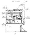
As shown in FIGS. 7-8, a dispenser 200 equipped with CIP system 100 may have a refrigerated compartment 146 having one or more product bag containers 156 in which one or more product containers, such as BIB containers, are disposed. Dispenser 200 may have one or more dispensing valves 34, 40 for dispensing product from one or more barrels 90, 92. Dispenser 200 may have a product compressor 140, a refrigerator compressor 142, one or more beater motors 144 for rotating beater bars (not shown) within barrels 90, 92, a dual circuit condenser 148, and a display 154 as known in the art. As shown in FIG. 9, an alternative dispenser 300 may have a high capacity refrigerator base 158 with multiple (such as eight, for example) product bag containers 156. In some embodiments, CIP system 100 may be configured as shown in FIGS. 10-11 within a dispenser such as dispenser 200 or 300.
Referring to FIGS. 12-14, a CIP connector 70 (which may be the same as CIP connector 80) may have an inlet with a threaded connector 186, an outlet with a hose connector 176, a syrup inlet vacuum transducer 64 which detects when a vacuum is present in syrup inlet passage 188, a syrup inlet vacuum transducer inlet fitting 192, and a hose in place sensor 178 which detects when a hose is in place on hose connector 176. Threaded connector 186 may be configured for connecting CIP connector 70 to threaded fitting 218 of BIB connector 66 (see FIGS. 18-19). A piston 194 may be disposed in a flow path 198 and may slide from a first position (not shown) in which flow path 198 is closed by an O-ring check seal 182 to a second position (shown in FIG. 13) in which flow path 198 is in fluid communication with outlet 176. A spring 184 may provide a biasing force on piston 194 to hold piston 194 in the first (closed) position. When inlet 238 of shaft 230 of BIB connector 66 (see FIG. 19) is inserted into flow path 198 and engages piston 194, piston 194 may be moved to the second (open) position in order to permit fluid to flow through CIP connector 70, at which point sensor trigger 196 may cause a signal to be sent to microcontroller 288 indicating that CIP connector 70 is connected to BIB connector 66. When BIB connector 66 is removed from CIP connector 70, spring 184 may cause piston 194 to return to the closed position. One or more mounting holes 190 may be provided to mount syrup inlet vacuum transducer 64 and hose in place sensor 178 to CIP connector 70.
Referring to FIGS. 15-17, nozzle cap 36 (which may be the same as nozzle cap 42) may have an open end with threads 214 for connecting nozzle cap 36 to dispensing valve 34. Threads 214 may be quarter-turn or other suitable threads. Alternatively, any other suitable means for connecting nozzle cap 36 to dispensing valve 34 may be used, such as press fit, quick connect, or the like. Nozzle cap 36 may have a cutout 202 to accommodate a drain conduit of dispensing valve 34. A sensor trigger 210 may be provided on nozzle cap 36 which may cause nozzle cap in place sensor 252 to send a signal to microcontroller 288 when nozzle cap 36 is connected to dispensing valve 34. Nozzle cap 36 may have a protrusion 212 with an internal reservoir 204 in which a cleaning/sanitizing agent 206 is disposed. A film 208 may be provided to seal cleaning/sanitizing agent 206 within reservoir 204 until film 208 is melted or dissolved due to contact with water or other fluid of a sufficient temperature, at which point cleaning/sanitizing agent 206 may be released from reservoir 204. In some embodiments, film 208 may not be present. Nozzle cap 36 may be a single use apparatus, or nozzle cap 36 may be used for more than one CIP process. In some embodiments, cleaning/sanitizing agent 206 may be in the form of a module or packet, and nozzle cap 36 may be refillable with such a module or packet for each use. As shown in FIGS. 15 and 17, nozzle cap 36 may have no inlet or outlet other than the open end.
Referring to FIGS. 18-19, BIB connector 66 (which may be the same as BIB connector 82) may have a connector body 222 with a shaft 230 slidably disposed therein. Shaft 230 may have a flow path 242 extending from an inlet 238 having a plurality of inlet ports 246 to an outlet having a plurality of outlet ports 248. Product may flow through shaft 230 as shown by flow path arrows 240. Shaft 230 may slide from a first position (not shown) in which outlet ports 248 are closed off to a second position (shown in FIG. 19) in which outlet ports 248 are in open fluid communication with flow path 244 and outlet fitting 220. A spring 224 may provide a biasing force on spring stop 232 to bias shaft 230 toward the closed position. A pair of retainer clips 216 may be mounted to connector body 222 with retaining pins 250, and springs 266 may provide a biasing torque to bias clips 216 in a closed or clamped position. Clips 216 may be used to fasten BIB connector 66 to a spout on a BIB product package 68 during normal operation of dispenser 200, 300. Threads 218 may be used to fasten BIB connector 66 to threaded connector 186 of CIP connector 70 during operation of CIP system 100 as described herein. Inlet 238 may be configured to mate with a spout on a BIB product package 68 and with piston 194 of CIP connector 70. A seal 236 may provide a sealing engagement of shaft 230 with a spout on a BIB product package 68. A retaining pin 234 may be provided to prevent shaft 230 from being completely withdrawn from BIB connector 66 and may also limit inward travel of shaft 230. A lower O-ring 226 and an upper O-ring 228 may be provided for sealing engagement of shaft 230 within body 222 to ensure shut-off of the flow path when shaft 230 is in the first (closed) position.
Referring to FIGS. 20-21, a water/drain quick disconnect water body 96 and a water/drain quick disconnect main body 98 may be joined together with one or more connectors 268 as shown. A water flow path 262 may extend from a water inlet fitting 256 through a quick disconnect water shut off 260 to a water inlet quick disconnect receiver 168, which may be configured to receive water quick disconnect fitting 172 (see FIG. 11). A drain flow path may extend from a drain outlet quick disconnect receiver 170 to a drain outlet fitting 258. Drain outlet quick disconnect receiver 170 may be configured to receive drain outlet quick disconnect fitting 174 (see FIG. 11). One or more mounting holes 150 may be provided for mounting water/drain quick disconnect water body 96 and water/drain quick disconnect main body 98 to dispenser 200, 300. Quick disconnect water shut off 260 may be used to easily shut off the water supply to CIP system 100. Together, water/drain quick disconnect water body 96 and water/drain quick disconnect main body 98 form an assembly by which dispenser 200, 300 may be quickly and easily connected to and disconnected from a water source and a drain.
CIP Process Flow Description
When a condition exists that requires the dispenser 200, 300 to be cleaned and sanitized as determined by preset conditions entered into microcontroller 288, or by an operator on demand, the operator may put in place a nozzle cap 36, 42 on the dispensing valve 34, 40. The BIB connector 66, 82 may then be removed from the product BIB 68, 78 and placed on the CIP connector 70, 80. Position sensors 252, 254 detect that nozzle caps 36, 42 are installed on dispensing valves 34, 40, and position sensors 178, 272 detect that BIB connectors 66, 82 are connected to the CIP connectors 70, 80. When both position sensors 252, 254 and position sensors 178, 272 detect the installed condition, the microcontroller 288 may initiate the Clean in Place (CIP) process as illustrated in FIG. 6 and further described below.
Defrost
In frozen food or beverage embodiments, when cleaning begins, product in barrel 90, 92 may be defrosted in a suitable manner, such as either through a heat pump cycle using a reversing valve in the primary refrigeration system of dispenser 200, 300 or by using a hot gas bypass in the primary refrigeration system, for example. As shown in FIG. 2, once the defrost cycle has been completed, the CIP drain solenoid 88 may be opened and the air injection system may be used to pressurize barrel 90, 92 and open a check valve 38, 48 integrated into the drain conduit for barrel 90, 92 thereby forcing product out of the drain of barrel 90, 92. When draining is complete, the air injection system may be deactivated thereby closing check valve 38, 48 and the drain solenoid 88 may be deactivated thereby closing the system drain.
Product Flush
When the drain cycle is complete, the water solenoid valve 52 and the CIP recirculation solenoid valve 72, 76 for the respective barrel 90, 92 may be energized open as shown in FIG. 3. During this timed event, the vent valve 30, 44 may be actuated allowing water to fill the barrel 90, 92 and overflow through the vent valve 30, 44 to flush any remaining defrosted liquid product out the vent conduit. Also during this timed event, the vent air solenoid 20, 26 may be energized and de-energized thereby opening and closing the barrel vent actuator 30, 44 at specific intervals to assist in flushing the vent conduit. The air injection solenoid 18, 28 may also cycle during this time to allow the barrel 90, 92 to reach a specific pressure during the fill process.
When the timed flush event is completed, the water solenoid 52 may be de-energized and the vent actuator 30, 44 may be closed. The CIP recirculation solenoid valve 72, 76 for the respective barrel 90, 92 may remain energized open and the solution of water and defrosted product may be circulated through the CIP system by use of a liquid pump 62, 86, ingredient fill conduit, and associated CIP plumbing. During this circulation of solution, agitation of the solution may occur in the barrel 90, 92 by rotating beater bars (not shown) inside barrel 90, 92 in clockwise and counter-clockwise directions using beater motors 144, 306, 270. During the circulation process, the dispense air solenoid 22, 24 may be actuated thereby opening the dispensing valve 34, 40. In some embodiments, the dispense air solenoid 22, 24 may be intermittently or periodically energized and de-energized to both open and close the dispensing valve 34, 40 thereby introducing agitation on the dispensing valve 34, 40. In some variations, this opening and closing of dispensing valve 34, 40 may be used to activate a pump integrated into nozzle cap 36, 42 to circulate fluid through the dispensing valve 34, 40. Also during the circulating process, the inline heater 74 or in alternate configurations the heat pump may be used to elevate the temperature of the rinse solution to a desired temperature. Although heater 74 is shown positioned upstream from the sanitizer injection point and the water injection point, heater 74 may be located in any desired position in the CIP circuit, and more than one heater may be used if desired.
After the set time for agitating is completed, the CIP recirculation solenoid valve 72, 76 for the respective barrel 90, 92 may be de-energized thereby closing the CIP recirculation solenoid valve 72, 76, and the fluid pump 62, 86 may be stopped. The CIP drain solenoid 88 and the dispense air solenoid 22, 24 may be energized thereby opening the dispensing valve 34, 40 and the CIP drain. Also at this time, if a heating method was initiated to elevate the temperature of the solution, it may be deactivated. Air may then be supplied by energizing the air injection solenoid 18, 28. This air pressure may be used to pressurize the barrel 90, 92 thereby opening a check valve 38, 48 integrated into the drain conduit for the barrel 90, 92 thereby forcing product out the drain of the barrel 90, 92. When draining is complete, the air injection solenoid 18, 28 and the drain solenoid 88 may be de-energized thereby closing the check valve stopping the drain cycle. The beater motor 144, 306, 270 may also be stopped at this time.
Barrel Cleaning
In some embodiments, when the drain solenoid valve 88 is de-energized closed, the respective CIP recirculation solenoid valve 72, 76 may be energized open and the sanitizer/cleaner solenoid valve 58 may be opened and the sanitizer/cleaner pump 60 may be activated for a set amount of time, as shown in FIG. 4. For example, a positive displacement solenoid pump 60 may be used to precisely meter the amount of cleaning/sanitizing agent that is introduced to the system. Upon completion of this timed event, the sanitizer/cleaner solenoid valve 58 may be de-energized closed, and the water solenoid valve 52 and the CIP recirculation solenoid valve 72, 76 for the respective barrel 90, 92 may be energized open. During this timed event, the vent valve 30, 44 may be actuated thereby allowing water to fill the barrel 90, 92 and overflow through the vent 30, 44 to flush any remaining defrosted liquid product out the vent conduit. Also during this timed event, the vent air solenoid 20, 26 may be energized and de-energized thereby opening and closing the vent actuator 30, 44 at specific intervals to assist in flushing the vent conduit. The air injection solenoid 18, 28 may also cycle during this time to allow the barrel 90, 92 to reach a specific pressure during the fill process.
Once the fill sequence is completed, the water solenoid valve 52 may be de-energized closed and the liquid pump 62, 86 may be deactivated. Also, if activated, the air injection 18, 28 and vent actuator 30, 44 may be deactivated. Then during a timed event the water/sanitizer/cleaner fluid may be agitated in the barrel 90, 92 by rotating the beater bars in clockwise and counter-clockwise directions. During this same time, in some embodiments, the dispense air solenoid 22, 24 may be energized and de-energized thereby opening and closing the dispensing valve 34, 40. Alternatively or additionally, the dispense air solenoid 22, 24 may be energized to leave the dispensing valve 34, 40 open. Also at this time, the barrel 90, 92 may be heated to an elevated temperature, such as over 100° F., for example, for a set time. The vent conduit of the barrel 90, 92 may also be flushed at this time. This may occur by energizing the vent solenoid 20, 26 open, actuating the CIP vent 30, 44, while at the same time with the CIP recirculation solenoid valve 72, 76 open, the water solenoid 52 is energized open to introduce water into the recirculation path forcing an overflow of cleaning solution into the vent conduit. This process may occur in singular form or may be repeated several times over a timed interval. Upon completion of the high temperature agitation and timed agitation events (dispense cycles, and beater rotations), the barrel 90, 92 may again be drained.
After the set time for agitating is completed, the CIP recirculation solenoid valve 72, 76 for the respective barrel 90, 92 may be de-energized thereby closing the CIP recirculation solenoid valve 72, 76, and the fluid pump 62, 86 may be stopped. The CIP drain solenoid 88 and the dispense air solenoid 22, 24 may be energized thereby opening the dispensing valve 34, 40 and the CIP drain. Also at this time, if a heating method was initiated to elevate the temperature of the solution, it may be deactivated. Air may then be supplied by energizing the air injection solenoid 18, 28. This air pressure may be used to pressurize the barrel 90, 92 thereby opening a check valve 38, 48 integrated into the drain conduit for the barrel 90, 92 thereby forcing product out the drain of the barrel 90, 92. When draining is complete, the air injection solenoid 18, 28 and the drain solenoid 88 may be de-energized thereby closing the check valve stopping the drain cycle. The beater bars may also be stopped at this time.
Cool Water Rinse
In some embodiments, the cool rinse may be omitted, and in other configurations either a heat pump system or an inline heater 74 may be used to elevate the temperature of the rinse solution during a circulation step. The water solenoid valve 52 may be energized open. During this timed event, the CIP drain solenoid 88 may be de-energized closed and the CIP recirculation solenoid valve 72, 76 may be energized open. The barrel 90 92 may then be filled by use of a liquid pump 62, 86, and ingredient fill conduit. As the barrel 90, 92 is filling, the vent air solenoid 20, 26 may be actuated to open and close the vent actuator 30, 44. The air injection solenoid 18, 28 may also cycle during this time to allow the barrel 90, 92 to reach a specific pressure upon high fill.
Once the fill sequence is completed, the water solenoid valve 52 may be de-energized closed and the fill water may be agitated in the barrel 90, 92 by rotating the beater bars in clockwise and counter-clockwise directions. In some embodiments, during this same time the dispense air solenoid 22, 24 may be energized and de-energized thereby opening and closing the dispensing valve 34, 40. In some embodiments, the dispense air solenoid 22, 24 may be energized thereby opening the dispensing valve 34, 40 for the length of timed event. Upon completion of the flush and timed agitation events (dispense cycles, and beater rotations), the barrel 90, 92 may again be drained.
The CIP recirculation solenoid valve 72, 76 for the respective barrel 90, 92 may be de-energized thereby closing the CIP recirculation solenoid valve 72, 76 and the fluid pump 62, 86 may be stopped. The CIP drain solenoid 88 and the dispense air solenoid 22, 24 may be energized thereby opening the dispensing valve 34, 40 and the CIP drain. Also at this time, if a heating method was initiated to elevate the temperature of the solution, it may be deactivated. Air may then be supplied by energizing the air injection solenoid 18, 28. This air pressure may be used to pressurize the barrel 90, 92 thereby opening check valve 38, 48 and thereby forcing product out the drain of the barrel 90, 92. When draining is complete, the air injection solenoid 18, 28 and the drain solenoid 88 may be de-energized thereby closing the check valve 38, 48 and stopping the drain cycle. The beater bars may also be stopped at this time.
Heated Water Sanitization
When the draining of barrel 90, 92 is complete, the water solenoid valve 52 may be energized open. During this timed event, the CIP drain solenoid 88 may be de-energized closed and the CIP recirculation solenoid valve 72, 76 may be energized open. The barrel 90, 92 may then be filled by use of a liquid pump 62, 86 and ingredient fill conduit. As the barrel 90, 92 is filling, the vent air solenoid 20, 26 may be energized and de-energized to open and close the vent actuator 30, 44 of barrel 90, 92. The air injection solenoid 18, 28 may also cycle during this time to allow the barrel 90, 92 to reach a specific pressure upon high fill. In some embodiments, an additional cleaning/sanitizing agent may be introduced into the CIP system during this timed event.
Once the fill sequence is completed, as shown in FIG. 5, the water solenoid valve 52 may be de-energized closed and the fill water may be agitated in the barrel 90, 92 by rotating the beater bars in clockwise and counter-clockwise directions. Also at this time the water may be circulated through the CIP system and the barrel 90, 92. With the use of an inline heater 74, or heat pump refrigeration system, the solution in the CIP system may be heated to a desired temperature, such as in excess of 165° F. or 170° F., for example, for a desired timed duration, such as about 30 seconds or more, for example. In some embodiments, less than 30 seconds may be sufficient. In some embodiments, during this time the dispense air solenoid 22, 24 may be energized and de-energized thereby opening and closing the dispensing valve 34, 40. In alternate configurations, the dispense air solenoid 22, 24 may be energized thereby opening the dispensing valve 34, 40 for the duration of the timed event. Upon completion of the heated flush and timed agitation events (dispense cycles, and beater rotations), the barrel 90, 92 may again be drained.
The CIP recirculation solenoid valve 72, 76 for the respective barrel 90, 92 may be de-energized thereby closing the CIP recirculation solenoid valve 72, 76, and the fluid pump 62, 86 may be stopped. The CIP drain solenoid 88 and the dispense air solenoid 22, 24 may be energized thereby opening the dispensing valve 34, 40 and the CIP drain. Also at this time, if a heating method was initiated to elevate the temperature of the solution, it may be deactivated. Air may then be supplied by energizing the air injection solenoid 18, 28. This air pressure may be used to pressurize the barrel 90, 92 thereby opening check valve 38, 48 and thereby forcing product out the drain of barrel 90, 92. When draining is complete, the air injection solenoid 18, 28 and the drain solenoid 88 may be de-energized thereby closing the check valve 38, 48 and stopping the drain cycle. The beater bars may also be stopped at this time.
At this time, the CIP process may be complete and the CIP system 100 may wait until the user disconnects the ingredient fill conduit from the CIP connector 70, 80 and removes the nozzle cap 36, 42 from dispensing valve 34, 40. An ingredient BIB 68, 78 or other product container may then be connected to the ingredient fill conduit and the barrel 90 92 may undergo a normal product fill routine. During set-up of dispenser 200, 300, the source of pressurizing gas can be set to use customer supplied CO2 or compressed air from an integral air pump 2. This gas may be used during all product fill and barrel pressurization routines. The CIP process described above may be used in a sealed beverage dispenser 200, 300, and the CIP process may also be adapted for use in “open hopper” dispensers that are open to atmospheric conditions and subsequent contamination.
In some embodiments, CIP systems as described herein may be used for pasteurizing and/or sterilizing products to be dispensed from food and beverage dispensers of which such CIP systems form a part. To accomplish this, nozzle cap 36, 42 may be put in place on dispensing valve 34, 40, and BIB connector 66, 82 may be connected to CIP connector 70, 80, and a heated circulate/agitate process may be conducted to pasteurize the product. In an alternate configuration, dispensing valve 34, 40 and nozzle cap 36, 42 may be replaced by a multiple position dispensing valve that has a double-acting dispensing valve actuator which allows the internal operator of the dispensing valve to rise up above a static position to dispense product and alternately lower below the static position to seal the product outlet and allow flow into the CIP circuit. The opening of this circuit allows for the product to circulate through the CIP system for heat pasteurization. Subsequently this arrangement allows for the pasteurization and/or sterilization of the product to be performed as required or desired.
Although the foregoing description contemplates manual connection and disconnection of nozzle cap 36, 42 and CIP connector 70, 80 to facilitate operation of the CIP process, persons of ordinary skill in the art will appreciate that the apparatus disclosed herein may be adapted such that automated switching between normal and CIP flow paths may be accomplished without the need for manual connection or disconnection of such components by a user. Additionally, it will be appreciated that the CIP process for barrels 90 and 92 may be accomplished independently or concurrently. The CIP system for each barrel 90, 92 may have its own water source, cleaner/sanitizer source, heater, pump, drain, and other components, or such components may be shared by a CIP system that serves both barrels 90 and 92. Also, in some embodiments, fewer than all of the aforementioned process steps may be performed or additional steps may be performed, depending on the desired application.
The embodiments described above are some examples of the current invention. Various modifications and changes of the current invention will be apparent to persons of ordinary skill in the art. Among other things, any feature described for one embodiment may be used in any other embodiment. Additionally, improvements described herein may be used in connection with the subject matter described in U.S. patent application Ser. No. 11/467,852 filed on Aug. 28, 2006, the disclosure of which is incorporated herein by reference. The scope of the invention is defined by the attached claims and other claims to be drawn to this invention, considering the doctrine of equivalents, and is not limited to the specific examples described herein.

Claims (5)

What is claimed is:
1. A method of cleaning a food or beverage dispenser having a product barrel in fluid communication with a drain conduit, a dispensing valve in fluid communication with said product barrel, a nozzle cap removably connectable in fluid communication with said dispensing valve, said nozzle cap comprising an open end and a reservoir and a cleaning/sanitizing agent disposed in said reservoir, said nozzle cap having no inlet or outlet other than said open end, a water inlet in fluid communication with said drain conduit, a CIP connector in fluid communication with said drain conduit, a BIB connector removably connectable in fluid communication with said CIP connector, wherein said BIB connector is configured for alternate connection to said CIP connector and a BIB package, and a pump in fluid communication with said BIB connector and said product barrel, said method comprising:
connecting said nozzle cap to said dispensing valve;
disconnecting said BIB connector from said BIB package;
connecting said CIP connector to said BIB connector; and
operating said pump to circulate water from said water inlet through said product barrel, said dispensing valve, said drain conduit, said CIP connector, and said BIB connector;
wherein said water passes into and out of said open end of said nozzle cap such that said cleaning/sanitizing agent is released from said reservoir into said water.
2. The method of claim 1 further comprising heating said water.
3. The method of claim 2 wherein said nozzle cap further comprises a film configured to seal said cleaning/sanitizing agent within said reservoir, and wherein said cleaning/sanitizing agent is released into said water by dissolving said film upon contact with said water at a predetermined temperature.
4. The method of claim 1 further comprising:
defrosting said product barrel;
filling said product barrel with water in a top-off filling;
draining said water and defrosted product from said product barrel in a first draining;
filling said product barrel with water in a first filling;
heating said water to a first temperature;
circulating said water through said dispenser in a first circulation cycle;
draining said water from said product barrel in a second draining;
filling said product barrel with water in a second filling;
heating said water to a second temperature;
circulating said water through said dispenser in a second circulation cycle;
draining said water from said product barrel in a third draining;
filling said product barrel with water in a third filling;
circulating said water through said dispenser in a third circulation cycle;
draining said water from said product barrel in a fourth draining;
filling said product barrel with water in a fourth filling;
heating said water to a third temperature;
circulating said water through said dispenser in a fourth circulation cycle;
cooling said water; and
draining said water from said product barrel in a fifth draining.
5. The method of claim 4 further comprising:
during at least one of said circulation cycles, agitating said water in said product barrel by rotating one or more beater bars within said product barrel.
US14/928,873 2011-12-02 2015-10-30 Method of cleaning a food or beverage dispenser Active US9457386B2 (en)

Priority Applications (1)

Application Number Priority Date Filing Date Title
US14/928,873 US9457386B2 (en) 2011-12-02 2015-10-30 Method of cleaning a food or beverage dispenser

Applications Claiming Priority (3)

Application Number Priority Date Filing Date Title
US201161566192P 2011-12-02 2011-12-02
US13/691,001 US9173521B2 (en) 2011-12-02 2012-11-30 Food and beverage dispenser with cleaning system
US14/928,873 US9457386B2 (en) 2011-12-02 2015-10-30 Method of cleaning a food or beverage dispenser

Related Parent Applications (1)

Application Number Title Priority Date Filing Date
US13/691,001 Continuation US9173521B2 (en) 2011-12-02 2012-11-30 Food and beverage dispenser with cleaning system

Publications (2)

Publication Number Publication Date
US20160089702A1 US20160089702A1 (en) 2016-03-31
US9457386B2 true US9457386B2 (en) 2016-10-04

Family

ID=48523275

Family Applications (2)

Application Number Title Priority Date Filing Date
US13/691,001 Active - Reinstated 2033-04-07 US9173521B2 (en) 2011-12-02 2012-11-30 Food and beverage dispenser with cleaning system
US14/928,873 Active US9457386B2 (en) 2011-12-02 2015-10-30 Method of cleaning a food or beverage dispenser

Family Applications Before (1)

Application Number Title Priority Date Filing Date
US13/691,001 Active - Reinstated 2033-04-07 US9173521B2 (en) 2011-12-02 2012-11-30 Food and beverage dispenser with cleaning system

Country Status (3)

Country Link
US (2) US9173521B2 (en)
CN (1) CN204797604U (en)
WO (1) WO2013082453A2 (en)

Cited By (6)

* Cited by examiner, † Cited by third party
Publication number Priority date Publication date Assignee Title
CN108393406A (en) * 2017-07-14 2018-08-14 芜湖浩博科技有限公司 Press Tools for Automobiles product pretreating machine
US10512276B2 (en) 2015-02-09 2019-12-24 Fbd Partnership, Lp Multi-flavor food and/or beverage dispenser
US10712063B2 (en) 2016-10-17 2020-07-14 Fbd Partnership, Lp Frozen product dispensing systems and methods
US10736337B2 (en) 2015-02-25 2020-08-11 Fbd Partnership, Lp Frozen beverage machine control system and method
US10788246B2 (en) 2015-02-25 2020-09-29 Fbd Partnership, Lp Frozen beverage machine control system and method
US11412757B2 (en) 2017-06-30 2022-08-16 Fbd Partnership, Lp Multi-flavor frozen beverage dispenser

Families Citing this family (31)

* Cited by examiner, † Cited by third party
Publication number Priority date Publication date Assignee Title
US9173521B2 (en) 2011-12-02 2015-11-03 Fbd Partnership, Lp Food and beverage dispenser with cleaning system
US10464799B2 (en) * 2012-12-19 2019-11-05 Beersmart, Llc System and method for beverage line cleaning
US9693571B2 (en) 2013-05-24 2017-07-04 Ali S.p.A.—Carpigiani Group Machine and method for making and dispensing liquid, semi-liquid and/or semi-solid food products
EP3046867B1 (en) 2013-09-16 2022-05-04 Idea Boxx, LLC Apparatus and method for cleaning a food processor
US10376934B2 (en) 2014-04-24 2019-08-13 Ali Group S.R.L.—Carpigiani Method for cleaning a machine for liquid or semi-liquid food products
SI2936992T1 (en) * 2014-04-24 2018-10-30 Ali S.P.A. - Carpigiani Group Method for cleaning a machine for liquid or semi-liquid food products
US10315815B2 (en) * 2015-01-01 2019-06-11 Waterio Ltd. Ingredient dispensing system for dispensing an ingredient into a container
US20160228831A1 (en) * 2015-02-05 2016-08-11 Claussen Technology, Llc Liquid transfer system
MX2017014590A (en) * 2015-05-22 2018-03-01 Lancer Corp Methods and apparatus for sanitizing dispensers.
US20170027185A1 (en) 2015-07-31 2017-02-02 Fbd Partnership, Lp Frozen beverage dispenser
DE102015217964A1 (en) * 2015-09-18 2017-03-23 Franke Kaffeemaschinen Ag Cleaning system for a device for dispensing liquid food
WO2017100681A1 (en) * 2015-12-11 2017-06-15 Idea Boxx, Llc Flow balancing in food processor cleaning system
CN107510364B (en) * 2016-06-15 2023-10-27 张永良 Full-automatic multifunctional direct drinking machine
CN106388613B (en) * 2016-06-27 2023-07-07 苏州华爱电子有限公司 Heating disinfection waterway system of water bottle underlying type water dispenser
CN106190772A (en) * 2016-07-15 2016-12-07 江苏尚昆生物设备有限公司 Material distributing system
US10327455B2 (en) 2016-07-30 2019-06-25 Fbd Partnership, Lp Dispensing system
KR20180066579A (en) * 2016-12-09 2018-06-19 엘지전자 주식회사 Drinking water supplying device and Controlling method for the same
KR20180066578A (en) * 2016-12-09 2018-06-19 엘지전자 주식회사 Drinking water supplying device and Controlling method for the same
WO2018136715A1 (en) * 2017-01-19 2018-07-26 The Coca-Cola Company Automated cleaning system for beverage dispensing machine
WO2018169949A1 (en) * 2017-03-13 2018-09-20 Fbd Partnership, Lp Frozen beverage machine control system and method
ES2941960T3 (en) * 2017-05-10 2023-05-29 Douwe Egberts Bv Beverage percolation appliance with cleaning of the outside of the spout
DE102017118598A1 (en) * 2017-08-15 2019-02-21 Franke Kaffeemaschinen Ag DEVICE FOR PREPARING HOT BEVERAGES
US20190070643A1 (en) * 2017-09-07 2019-03-07 Fbd Partnership. Lp Beverage dispenser cleaning methods and apparatus
KR102587228B1 (en) * 2017-11-17 2023-10-11 엘지전자 주식회사 Beverage maker
DE102018205832A1 (en) * 2018-04-17 2019-10-17 Krones Ag PROCESS FOR CLEANING PROCESS PLANTS
CN109602278A (en) * 2019-01-16 2019-04-12 浙江鸣食品股份有限公司 A kind of liquid beverage now adjusts equipment and its modulator approach automatically
AT522466B1 (en) * 2019-08-02 2020-11-15 Redl Gmbh Beverage preparation device with a washing device
CN110169726B (en) * 2019-06-25 2022-01-04 九阳股份有限公司 Cleaning method of food processor
EP3847898B1 (en) * 2020-01-10 2022-12-21 Frigomat S.r.l. Machine for the production of liquid, semi-liquid or pasty solid food products equipped with automatic washing system and method for cleaning such a machine
WO2021201935A1 (en) * 2020-03-30 2021-10-07 Chemtreat, Inc. Methods and systems for online cleaning of beverage fillers
US20240010485A1 (en) * 2022-07-11 2024-01-11 Quality Mark, Inc. Cleaning device for beverage dispenser nozzle

Citations (26)

* Cited by examiner, † Cited by third party
Publication number Priority date Publication date Assignee Title
US2969073A (en) 1958-03-24 1961-01-24 Charles Barancik Container washing apparatus
US3410303A (en) * 1966-11-09 1968-11-12 Johnson Entpr Inc Cover for a dispensing faucet
US3677272A (en) 1970-11-23 1972-07-18 Shirley L Schrank Cleaning device for beverage dispensers
US4213795A (en) 1977-02-18 1980-07-22 Tetra Pak International Ab Method and an arrangement for the cleaning and sterilizing of a filler pipe on a packing machine
US4784697A (en) 1986-02-14 1988-11-15 Tetra Dev-Co. Method and an arrangement on packing machines
US5329950A (en) 1993-05-14 1994-07-19 Sanirab Corporation Clean-in-place process and equipment
US5740844A (en) 1996-04-23 1998-04-21 Tetra Laval Holdings & Finance S.A. Fill system including a fill valve housing with interchangeable sanitary cover and clean-in-place manifold
US6126045A (en) 1997-07-21 2000-10-03 Itsac N.V. Connector assembly for a fluid connection
US6223948B1 (en) 1999-08-02 2001-05-01 Lancer Partnership, Ltd Additive injector for a dispensing valve
US6331432B1 (en) 2000-07-11 2001-12-18 Nestec S.A. Device and method for cleaning and sanitizing a food reservoir
US20020043071A1 (en) * 2000-08-18 2002-04-18 Frank Jimmy I. Frozen beverage machine
US6457497B1 (en) 1999-01-06 2002-10-01 Sidel Filling machine comprising advanced cleaning means
US6490872B1 (en) 1999-05-20 2002-12-10 Specialty Equipment Companies, Inc. Apparatus and a method for clean-in-place for a semi-frozen food dispensing machine
US6889603B2 (en) 2002-12-24 2005-05-10 Nestec S.A. Clean-in-place automated food or beverage dispenser
US20060186137A1 (en) 2003-08-11 2006-08-24 Rudolf Till Dispensing system for beverages and method for cleaning a dispensing system
US20070062212A1 (en) * 2005-08-26 2007-03-22 Fbd Partnership Lp Food dispensing machine
US20080203113A1 (en) 2007-02-28 2008-08-28 Banner Beverage Systems Company Beverage tap plug
US20080302824A1 (en) 2005-09-13 2008-12-11 Karel Blomme Metering Valve Comprising a Fixed Inner Conduit and a Mobile Outer Sleeve
US20090014464A1 (en) * 2007-07-13 2009-01-15 The Coca-Cola Company Clean in Place System for Beverage Dispensers
US7562793B2 (en) 2005-02-08 2009-07-21 Nestec S.A. Dispensing device with self-cleaning nozzle
WO2009124786A1 (en) * 2008-04-07 2009-10-15 Nestec S.A. Beverage preparation device with in-line scale removal system and descaling method using such system
US20100044395A1 (en) 2007-03-13 2010-02-25 0736413 B.C. Ltd. Disinfectant cap for sterile liquid dispenser
US20100242993A1 (en) 2005-11-17 2010-09-30 Becton, Dickinson And Company Patient fluid line access valve antimicrobial cap/cleaner
US20110248052A1 (en) 2004-09-07 2011-10-13 Kelly Albert R Recharge insert for cleaning, sanitizing or disinfectant fluid spray system
US20110253730A1 (en) 2010-04-19 2011-10-20 Isenberg Timothy J Food Processing Vat With A Clean-In-Place Vent
WO2013082453A2 (en) 2011-12-02 2013-06-06 Fbd Partnership, Lp. Food and beverage dispenser with cleaning system

Patent Citations (32)

* Cited by examiner, † Cited by third party
Publication number Priority date Publication date Assignee Title
US2969073A (en) 1958-03-24 1961-01-24 Charles Barancik Container washing apparatus
US3410303A (en) * 1966-11-09 1968-11-12 Johnson Entpr Inc Cover for a dispensing faucet
US3677272A (en) 1970-11-23 1972-07-18 Shirley L Schrank Cleaning device for beverage dispensers
US4213795A (en) 1977-02-18 1980-07-22 Tetra Pak International Ab Method and an arrangement for the cleaning and sterilizing of a filler pipe on a packing machine
US4784697A (en) 1986-02-14 1988-11-15 Tetra Dev-Co. Method and an arrangement on packing machines
US5329950A (en) 1993-05-14 1994-07-19 Sanirab Corporation Clean-in-place process and equipment
US5740844A (en) 1996-04-23 1998-04-21 Tetra Laval Holdings & Finance S.A. Fill system including a fill valve housing with interchangeable sanitary cover and clean-in-place manifold
US6126045A (en) 1997-07-21 2000-10-03 Itsac N.V. Connector assembly for a fluid connection
US6457497B1 (en) 1999-01-06 2002-10-01 Sidel Filling machine comprising advanced cleaning means
US6490872B1 (en) 1999-05-20 2002-12-10 Specialty Equipment Companies, Inc. Apparatus and a method for clean-in-place for a semi-frozen food dispensing machine
US6223948B1 (en) 1999-08-02 2001-05-01 Lancer Partnership, Ltd Additive injector for a dispensing valve
US6331432B1 (en) 2000-07-11 2001-12-18 Nestec S.A. Device and method for cleaning and sanitizing a food reservoir
US20020043071A1 (en) * 2000-08-18 2002-04-18 Frank Jimmy I. Frozen beverage machine
US20030126871A1 (en) 2000-08-18 2003-07-10 Lancer Fbd Frozen beverage machine and method of operation
US6889603B2 (en) 2002-12-24 2005-05-10 Nestec S.A. Clean-in-place automated food or beverage dispenser
US7401613B2 (en) * 2002-12-24 2008-07-22 Nestec S.A. Clean-in-place automated food or beverage dispenser
US20060186137A1 (en) 2003-08-11 2006-08-24 Rudolf Till Dispensing system for beverages and method for cleaning a dispensing system
US20110248052A1 (en) 2004-09-07 2011-10-13 Kelly Albert R Recharge insert for cleaning, sanitizing or disinfectant fluid spray system
US7562793B2 (en) 2005-02-08 2009-07-21 Nestec S.A. Dispensing device with self-cleaning nozzle
US20070062212A1 (en) * 2005-08-26 2007-03-22 Fbd Partnership Lp Food dispensing machine
US8079230B2 (en) 2005-08-26 2011-12-20 Fbd Partnership, Lp Food dispensing machine
US20080302824A1 (en) 2005-09-13 2008-12-11 Karel Blomme Metering Valve Comprising a Fixed Inner Conduit and a Mobile Outer Sleeve
US20100242993A1 (en) 2005-11-17 2010-09-30 Becton, Dickinson And Company Patient fluid line access valve antimicrobial cap/cleaner
US20080203113A1 (en) 2007-02-28 2008-08-28 Banner Beverage Systems Company Beverage tap plug
US20100044395A1 (en) 2007-03-13 2010-02-25 0736413 B.C. Ltd. Disinfectant cap for sterile liquid dispenser
US20090014464A1 (en) * 2007-07-13 2009-01-15 The Coca-Cola Company Clean in Place System for Beverage Dispensers
WO2009124786A1 (en) * 2008-04-07 2009-10-15 Nestec S.A. Beverage preparation device with in-line scale removal system and descaling method using such system
US20110192423A1 (en) 2008-04-07 2011-08-11 Nestec S.A. Beverage preparation device with in-line scale removal system and descaling method using such system
US20110253730A1 (en) 2010-04-19 2011-10-20 Isenberg Timothy J Food Processing Vat With A Clean-In-Place Vent
WO2013082453A2 (en) 2011-12-02 2013-06-06 Fbd Partnership, Lp. Food and beverage dispenser with cleaning system
US20130140328A1 (en) 2011-12-02 2013-06-06 Fbd Partnership, Lp Food and beverage dispenser with cleaning system
US9173521B2 (en) 2011-12-02 2015-11-03 Fbd Partnership, Lp Food and beverage dispenser with cleaning system

Non-Patent Citations (1)

* Cited by examiner, † Cited by third party
Title
International Search Report and Written Opinion issued in co-pending PCT Patent App. No. PCT/US12/67336 dated Feb. 19, 2013 (10 pages).

Cited By (9)

* Cited by examiner, † Cited by third party
Publication number Priority date Publication date Assignee Title
US10512276B2 (en) 2015-02-09 2019-12-24 Fbd Partnership, Lp Multi-flavor food and/or beverage dispenser
US11252976B2 (en) 2015-02-09 2022-02-22 Fbd Partnership, Lp Multi-flavor food and/or beverage dispenser
US11297850B2 (en) 2015-02-09 2022-04-12 FBD Partnership, IP Multi-flavor food and/or beverage dispenser
US10736337B2 (en) 2015-02-25 2020-08-11 Fbd Partnership, Lp Frozen beverage machine control system and method
US10788246B2 (en) 2015-02-25 2020-09-29 Fbd Partnership, Lp Frozen beverage machine control system and method
US11849738B2 (en) 2015-02-25 2023-12-26 Fbd Partnership, Lp Frozen beverage machine control system and method
US10712063B2 (en) 2016-10-17 2020-07-14 Fbd Partnership, Lp Frozen product dispensing systems and methods
US11412757B2 (en) 2017-06-30 2022-08-16 Fbd Partnership, Lp Multi-flavor frozen beverage dispenser
CN108393406A (en) * 2017-07-14 2018-08-14 芜湖浩博科技有限公司 Press Tools for Automobiles product pretreating machine

Also Published As

Publication number Publication date
US20160089702A1 (en) 2016-03-31
WO2013082453A3 (en) 2015-06-25
CN204797604U (en) 2015-11-25
US9173521B2 (en) 2015-11-03
US20130140328A1 (en) 2013-06-06
WO2013082453A2 (en) 2013-06-06

Similar Documents

Publication Publication Date Title
US9457386B2 (en) Method of cleaning a food or beverage dispenser
US6625993B2 (en) Frozen beverage machine and method of operation
US11821415B2 (en) Liquid product dispensing system and method
US7708838B2 (en) Sanitary manifold system and method for hygienically dispensing fluids
AU2021212142B2 (en) Frozen dispensing machine heat treatment system and method
US10571041B2 (en) Bi-stable changeover valve
US8534503B2 (en) Device for preparing drinks and method for cleaning such a device
US20150272163A1 (en) Apparatus for producing soft ice cream
AU2021212143A1 (en) Frozen dispensing machine heat treatment system and method
US7595470B1 (en) Method and apparatus for heating and aseptic dispensing of sterile product
US7111759B1 (en) Sanitary, vented and disposable dispensing assembly for post mix beverage dispenser
US11758920B1 (en) Sealed, self-cleaning, food dispensing system including pump and bypass passage
US11920836B2 (en) Sealed, self-cleaning, food dispensing system with advanced refrigeration features
US20230380443A1 (en) Sealed, Self-Cleaning, Food Dispensing System
US20230380442A1 (en) Sealed, Self-Cleaning, Food Dispensing System with Variable Overrun Control
JPH06508328A (en) Post-mix beverage dispensing system
WO2023205818A1 (en) Sealed, self-cleaning, food dispensing system including fluid pump and bypass passage
WO2018191136A1 (en) Beverage distribution assembly
US20240141884A1 (en) Liquid product dispensing system and method

Legal Events

Date Code Title Description
AS Assignment

Owner name: FBD PARTNERSHIP, LP, TEXAS

Free format text: ASSIGNMENT OF ASSIGNORS INTEREST;ASSIGNORS:GATES, MATTHEW GRAYSON;FRANK, JIMMY IRVING;RENAUD, DAVID A.;REEL/FRAME:036951/0156

Effective date: 20120106

STCF Information on status: patent grant

Free format text: PATENTED CASE

MAFP Maintenance fee payment

Free format text: PAYMENT OF MAINTENANCE FEE, 4TH YR, SMALL ENTITY (ORIGINAL EVENT CODE: M2551); ENTITY STATUS OF PATENT OWNER: SMALL ENTITY

Year of fee payment: 4

FEPP Fee payment procedure

Free format text: 7.5 YR SURCHARGE - LATE PMT W/IN 6 MO, SMALL ENTITY (ORIGINAL EVENT CODE: M2555); ENTITY STATUS OF PATENT OWNER: SMALL ENTITY

MAFP Maintenance fee payment

Free format text: PAYMENT OF MAINTENANCE FEE, 8TH YR, SMALL ENTITY (ORIGINAL EVENT CODE: M2552); ENTITY STATUS OF PATENT OWNER: SMALL ENTITY

Year of fee payment: 8