EP1233228A2 - Ensemble connecteur pour une connexion fluidique - Google Patents
Ensemble connecteur pour une connexion fluidique Download PDFInfo
- Publication number
- EP1233228A2 EP1233228A2 EP02076283A EP02076283A EP1233228A2 EP 1233228 A2 EP1233228 A2 EP 1233228A2 EP 02076283 A EP02076283 A EP 02076283A EP 02076283 A EP02076283 A EP 02076283A EP 1233228 A2 EP1233228 A2 EP 1233228A2
- Authority
- EP
- European Patent Office
- Prior art keywords
- plug
- male part
- bore
- connector assembly
- wall
- Prior art date
- Legal status (The legal status is an assumption and is not a legal conclusion. Google has not performed a legal analysis and makes no representation as to the accuracy of the status listed.)
- Withdrawn
Links
Images


Classifications
-
- F—MECHANICAL ENGINEERING; LIGHTING; HEATING; WEAPONS; BLASTING
- F16—ENGINEERING ELEMENTS AND UNITS; GENERAL MEASURES FOR PRODUCING AND MAINTAINING EFFECTIVE FUNCTIONING OF MACHINES OR INSTALLATIONS; THERMAL INSULATION IN GENERAL
- F16L—PIPES; JOINTS OR FITTINGS FOR PIPES; SUPPORTS FOR PIPES, CABLES OR PROTECTIVE TUBING; MEANS FOR THERMAL INSULATION IN GENERAL
- F16L55/00—Devices or appurtenances for use in, or in connection with, pipes or pipe systems
- F16L55/10—Means for stopping flow from or in pipes or hoses
- F16L55/115—Caps
-
- B—PERFORMING OPERATIONS; TRANSPORTING
- B65—CONVEYING; PACKING; STORING; HANDLING THIN OR FILAMENTARY MATERIAL
- B65D—CONTAINERS FOR STORAGE OR TRANSPORT OF ARTICLES OR MATERIALS, e.g. BAGS, BARRELS, BOTTLES, BOXES, CANS, CARTONS, CRATES, DRUMS, JARS, TANKS, HOPPERS, FORWARDING CONTAINERS; ACCESSORIES, CLOSURES, OR FITTINGS THEREFOR; PACKAGING ELEMENTS; PACKAGES
- B65D41/00—Caps, e.g. crown caps or crown seals, i.e. members having parts arranged for engagement with the external periphery of a neck or wall defining a pouring opening or discharge aperture; Protective cap-like covers for closure members, e.g. decorative covers of metal foil or paper
- B65D41/02—Caps or cap-like covers without lines of weakness, tearing strips, tags, or like opening or removal devices
-
- B—PERFORMING OPERATIONS; TRANSPORTING
- B65—CONVEYING; PACKING; STORING; HANDLING THIN OR FILAMENTARY MATERIAL
- B65D—CONTAINERS FOR STORAGE OR TRANSPORT OF ARTICLES OR MATERIALS, e.g. BAGS, BARRELS, BOTTLES, BOXES, CANS, CARTONS, CRATES, DRUMS, JARS, TANKS, HOPPERS, FORWARDING CONTAINERS; ACCESSORIES, CLOSURES, OR FITTINGS THEREFOR; PACKAGING ELEMENTS; PACKAGES
- B65D51/00—Closures not otherwise provided for
-
- B—PERFORMING OPERATIONS; TRANSPORTING
- B65—CONVEYING; PACKING; STORING; HANDLING THIN OR FILAMENTARY MATERIAL
- B65D—CONTAINERS FOR STORAGE OR TRANSPORT OF ARTICLES OR MATERIALS, e.g. BAGS, BARRELS, BOTTLES, BOXES, CANS, CARTONS, CRATES, DRUMS, JARS, TANKS, HOPPERS, FORWARDING CONTAINERS; ACCESSORIES, CLOSURES, OR FITTINGS THEREFOR; PACKAGING ELEMENTS; PACKAGES
- B65D75/00—Packages comprising articles or materials partially or wholly enclosed in strips, sheets, blanks, tubes, or webs of flexible sheet material, e.g. in folded wrappers
- B65D75/52—Details
- B65D75/58—Opening or contents-removing devices added or incorporated during package manufacture
- B65D75/5861—Spouts
- B65D75/5872—Non-integral spouts
-
- Y—GENERAL TAGGING OF NEW TECHNOLOGICAL DEVELOPMENTS; GENERAL TAGGING OF CROSS-SECTIONAL TECHNOLOGIES SPANNING OVER SEVERAL SECTIONS OF THE IPC; TECHNICAL SUBJECTS COVERED BY FORMER USPC CROSS-REFERENCE ART COLLECTIONS [XRACs] AND DIGESTS
- Y10—TECHNICAL SUBJECTS COVERED BY FORMER USPC
- Y10T—TECHNICAL SUBJECTS COVERED BY FORMER US CLASSIFICATION
- Y10T137/00—Fluid handling
- Y10T137/7722—Line condition change responsive valves
- Y10T137/7837—Direct response valves [i.e., check valve type]
- Y10T137/7879—Resilient material valve
- Y10T137/7888—With valve member flexing about securement
- Y10T137/7889—Sleeve
-
- Y—GENERAL TAGGING OF NEW TECHNOLOGICAL DEVELOPMENTS; GENERAL TAGGING OF CROSS-SECTIONAL TECHNOLOGIES SPANNING OVER SEVERAL SECTIONS OF THE IPC; TECHNICAL SUBJECTS COVERED BY FORMER USPC CROSS-REFERENCE ART COLLECTIONS [XRACs] AND DIGESTS
- Y10—TECHNICAL SUBJECTS COVERED BY FORMER USPC
- Y10T—TECHNICAL SUBJECTS COVERED BY FORMER US CLASSIFICATION
- Y10T137/00—Fluid handling
- Y10T137/8593—Systems
- Y10T137/87917—Flow path with serial valves and/or closures
- Y10T137/88054—Direct response normally closed valve limits direction of flow
Definitions
- the present invention concerns a connector assembly for a fluid connection according to the preamble of claim 1.
- Such a connector assembly is known, for instance, from US 4 375 864.
- the present invention provides a connector assembly according to claim 1.
- the connector assembly shown is intended for providing a fluid connection for fluids, gases, liquid substances, such as soap, cosmetic creams, soft drink syrup, etcetera.
- the connector assembly is also suitable for powders, in particular fine powders, having suitable flow properties to flow through such a connector, such as coffee powder and the like or toner powder for printers and copiers, etcetera.
- the female part of the connector assembly could then be part of a cartridge containing the powder, whereas the male part is part of the copier, printer or coffee machine.
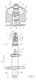
- the connector assembly in fact comprises three components: a female part 1, a male part 2 which can be connected to it, and a plug 3.
- the female part 1 and the plug 3 are preferably manufactured as a unitary plastic object in a suitable mould by means of injection moulding.
- the male part 2 may also be manufactured as a plastic injection moulding product, but the male part 2 may also be made of metal, for instance stainless steel.
- the female part 1 has a body with a front end 5 and a rear end 6, with an axial and essentially cylindrical bore 7 extending through the body from the insert opening 4 for the male part 2 at the front end 5; this bore 7 is open at both ends.
- the edge at the transition from the front end 5 to the bore 7 is bevelled.
- the bore 7 is bounded by a ring wall 8 protruding from the body.
- the inner surface of the ring wall 8 forms a seat 9 for the plug 3 extending around the bore 7; this plug 3 serves for closing of the bore 7.
- the body of the female part 1 is especially suited for being welded or glued into the wall or a seam of a flexible plastic bag.
- the body of the female part 1 can also be laid out to be placed in the neck of a bottle or similar container, or in a stable ring-shaped holder fitted to a flexible bag.
- the latter design is known notably for so-called "bag-in-box" systems.
- the male part 2 has a tubular end piece 10 fitting into the bore 7 of the female part 1.
- a radially protruding stop ridge 11 of the male part 2 rests against the front end 5 of the female part 1.
- the male part 2 further comprises a tubular part 12, connected to the endpiece 10, with a ring-shaped projection 13 to facilitate handling of the male part 2.
- a hose coupling part 14 Connected to the tubular part 12 is a hose coupling part 14, enabling the male part 2 to be connected to a hose (not shown).
- the male part 2 contains an internal axial passage 15, indicated by dotted lines, for the fluid.
- the axial passage 15 is open at the end of the hose connection part 14 and is blind at the other end, which means that the passage 15 does not extend to the tip of the end piece 10 but stops at some distance of this.
- Within the male part 2 a number, in this case four, of cross passages 17 have been formed, which connect the axial passage 15 near its blind end with the perimeter of the male part 2.
- the male part 2 further comprises at its perimeter two diametrically opposed blocking devices 19, which extend parallel with the longitudinal axis of the male part 2 from the stop ridge 11 in the direction of the tip of the end piece 10.
- the female part 1 is provided with two diametrically opposed grooves 20, extending in axial direction along the bore 7, which serve to receive the blocking devices 19 when the male part 2 is inserted into the bore 7.
- the cooperation between the blocking devices 19 and the grooves 20 prevents the male part 2 from turning with respect to the female part 1 before the male element 2 is connected to the plug 3, as will be explained further on.
- the blocking devices 19 and the grooves 20 make it easier to insert the male part 2 into the bore 7.
- it is possible to obtain a kind of key so that a unique combination of a female part 1 and a male part 2 is obtained and a connection between non-matching male and female parts is prevented.
- the end piece 10 is further provided with a ring-shaped groove 22 to receive a sealing ring (not shown here to avoid confusion), which establishes the seal between the male part 2 and the female part 1 and also contributes to holding the male part 2 in the bore 7.
- the groove 22 is located in the area between the cross passages 17 and the stop ridge 11.
- a ridge can be provided at the outside of the male part 2.
- the tip of the end piece 10 of the male part 2 is constructed as an essentially conical head 23 with at its extremity an essentially cylindrical projection 24.
- the head 23 first has a locating surface 25, coned towards the outside, and contiguous with this a gripping surface 26, outwardly tapered at a small cone angle towards the outside.
- Contiguous with the gripping surface 26 is a shoulder surface 27, tapered towards the inside, which ends at the bottom of a recess, formed by the circumferential groove 28, between the head 23 and the part of the male part 2 that is provided with cross passages 17.
- the head 23 is provided with two diametrically opposed grooves 29, which extend from the tip of the end piece 10 to behind the head 23 and end in the groove-shaped recess 28.
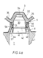
- the plug 3 has a ring wall 31 and an end wall 32, which together enclose a cavity 33 in plug 3 which is open towards the insert opening 4; this cavity 33 is intended to receive the head 23 of the male part 2.
- the end wall 32 forms a cylindrical recess 34, whose diameter is adjusted to the diameter of the cylindrical projection 24 of the head 23. This complementary shape ensures that the plug 3 will remain seated in the correct position on the head 23 and will not tilt.
- the inner surface of the ring wall 31 is made complementary to the head 23 of the male part 2.
- the grooves 29 allow any substance present in the cavity 33 to escape via the grooves 29 when the head 23 enters the cavity 33.
- the plug 3 is connected with the body of the female part 1 by two flexible bodies 35.
- the bodies 35 ensure that the plug 3 cannot be separated from the female part 1. Furthermore, the length of the bodies 35 is such that when the connector assembly is in the position shown in Figure 1, the male part 2 can connect with the plug 3.
- the plug 3 has a radially expandable and compressible ring-shaped collar 40, which forms a whole with plug 3.
- the collar 40 has an interior surface 41, tapered from its free edge towards the inside, which connects to a shoulder surface 42 coned towards the outside, which in turn connects to the inside of ring wall 31.
- the collar 40 further has an exterior surface 44, tapered from its free edge towards the outside, which connects to a ring-shaped hooking surface 45 which is coned towards the inside, which in turn connects to the outer surface of ring wall 31.
- the plug 3 further has a sealing rim 46 located around the outside of the ring wall 31 and protruding towards the outside.
- the plug 3 also has an outward protruding ring-shaped stop surface 47 at the side of the sealing rim 46 which faces away from the collar 40.
- the ring wall 8 has an axial end face 50, against which the stop surface 47 of the plug 3 rests when the plug 3 is in its seat 9.
- the bore 7 has a first part with such a diameter that the male part 2 can be inserted in it with a light drive fit.
- the first part changes to a second part of bore 7 with a slightly smaller diameter.
- a shallow circumferential groove 53 in the bore 7 is located so that the sealing ring (not shown) of the male part 2, inserted fully into the female part 1, engages partly in this groove, so that on the one hand a reliable seal is obtained and on the other hand a kind of snap connection is obtained.
- the ring wall 8 has (see Fig. 4a), viewed from the end face 50 in the direction of the insert opening 4, a cylindrical sealing surface 54, with an inner diameter that is slightly smaller than the outer diameter of the sealing rim 46 of the plug 3. Consequently the plug 3 with its sealing rim 46 will fit tightly in the ring wall 8, thus establishing a radial seal.
- an inward coned transition surface 55 connects to the sealing surface 54; this transition surface 55 in its turn passes into an outward coned shoulder surface 56 of the bore 7.
- a transition surface 57 Connected to this conical shoulder surface 56 is a transition surface 57, coned outwards at a smaller angle, which connects to the second cylindrical part of the bore 7.
- Figure 4a shows in which way the plug 3, located in its seat, closes off the bore 7.
- the plug 3 rests with its stop surface 47 against the end face 50 of the ring wall 8 and presses the sealing rim 46 into the ring wall 8.
- the collar 40 is in its first position and the ring-shaped smooth hooking surface 45 of the plug 3 rests at an elastic prestress against the shoulder surface 56 of the bore 7. Note that the contact of the stop surface 47 against the end face 50 provides a second seal of the bore 7.
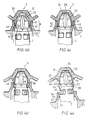
- FIG. 4b shows the situation when the head 23 of the male part 2 is inserted into the cavity 33 of the plug 3.
- the smallest diameter of the gripping surface 26 of the head 23 is smaller than the smallest diameter of the interior surface 41 in the first position of the collar 40 and as the taper angle of the interior surface 41 of the collar 40 is larger than the taper angle of the gripping surface 26 of the head 23, contact between the head 23 and the collar 40 is made especially at the location of the transition rim of the interior surface 41 to the shoulder surface 42 of the plug 3.
- Figure 4c shows the situation when the head 23 of the male part 2 is located entirely in the cavity 33 of the plug 3.
- the cylindrical projection 24 of the head 23 fits in the recess 34.
- the collar 40 has sprung back elastically from its second position as shown in Figure 4b to a third position.
- This third position is slightly further outward than the first position shown in Figure 4a, so the shoulder surface 42 of the plug 3 lies under prestress against the shoulder surface 27 of the head 23 and thus holds the head 23 in the plug 3 in a reliable way.
- the shoulder surface 56 of the bore 7 exerts a reaction force on the hooking surface 45 of the collar 40, which leads to an inward bending moment on the collar 40, again with respect to the thin connection of the collar 40 to the ring wall 31.
- the collar 40 can easily be compressed radially and so the diameter of the collar 40 decreases. Consequently the hooking surface 45 becomes more parallel to the axis of the male part 2, so that the force exerted via the hooking surface 45 on the ring wall 8 causes the ring wall 8 to expand radially to a greater degree.
- the collar 40 can pass the smallest diameter of the shoulder surface 56 of the bore 7 in a fourth position, pressed further inward, thus coming in the position shown in Figure 4d.
- the collar 40 is compressed radially, back to its fourth position, so that the force which is required to pull the head 23 from the plug 3 has become so much greater that first the plug 3 is pulled completely from its seat 9.
- the collar 40 subsequently passes the transition edge between the transition surface 55 and the shoulder surface 56 of the bore 7.
- the shoulder surface 27 of the head 23 exerts an outward bending moment on the collar 40; at that moment this collar 40 can easily expand again radially to its second position. As a result the head 23 can then be pulled from the plug 3 with a small force and subsequently the collar 40 springs back to its first position.
- the connector assembly it is possible to dimension as desired the axial force required during the different phases of connecting and disconnecting the male and female parts. For instance, it is possible to keep the axial force essentially constant during all the phases described above. In particular it is possible with the connector assembly described here that the axial force required to connect the male part 2 with the plug 3 is essentially equal to the axial force required to push the plug 3 subsequently from the bore 7.
- the cross section of the collar 40 is not uniform along its entire perimeter, but is built up from segments which are separated from each other by axial dividing seams or are connected to each other by thin bridging parts designed as thin film.
- the collar 40 may also be replaced by several discrete hooking fingers around the perimeter of the plug 3.
- Figure 5 shows one end, to be inserted into a female part, of a preferred embodiment of the male part 100 according to the invention.
- the male part 100 is very similar to the male part 2 described earlier, to which reference is made here, and can also be used in combination with the female part 1.
- the male part 100 is provided with an internal closing part, as will be explained below.
- the male part 100 has an internal axial passage 101 for a liquid, which is open on one end and is made blind at the tip of the insert end, and ends at an end wall 103.
- Several cross passages 105 have been provided, in this case four around the perimeter of the male part 100, each extending from the outer surface of the male part 100 to an outlet in the axial passage 101.
- a closing body 110 is fitted, which is shown separately in Figure 5.
- the closing body 110 is essentially cup-shaped with a flexible ring wall 111, which is intended to lie under prestress against the interior wall of the axial passage 101, thereby closing off the outlets of the cross passages 105.
- the flexible ring wall 111 can bend radially inward so as to provide a passage for the liquid.
- a suitable design of the closing body 110 makes it possible to choose the prestress with which the ring wall 111 presses against the axial passage 101 and the rigidity of the ring wall 111 in such a way that a passage is only created when there is a certain pressure difference between the inside and the outside of the ring wall 111.
- the closing body 110 acts as a non-return valve.
- the closing body 110 has a cross wall 112, transverse to the flexible ring wall 111, with a central opening in it (not discernible here).
- the closing body 110 can be removed from the male part 100 for cleaning or changing.
- Moulded to the end wall 103 of the axial passage 101 is a shank 114 with two diametrically opposed radial projections 115 at some distance from the end wall 103.
- the shank 114 protrudes through the opening in the cross wall 112 of the closing body 110, so that the projections 115 hook behind the cross wall 112 of the closing body 110.
- the closing body 110 is preferably an undivided object of a suitable rubber, silicone or elastomer and can be manufactured by injection moulding. As the closing body covers the outlets of the cross passages 105 the chance of undesired contamination of the axial passage, or a substance present in this, is minimal. It is also possible with this closing body 110 to prevent the presence of undesired air when making the connection with a suitable female part.
Applications Claiming Priority (3)
| Application Number | Priority Date | Filing Date | Title |
|---|---|---|---|
| NL1006636 | 1997-07-21 | ||
| NL1006636A NL1006636C2 (nl) | 1997-07-21 | 1997-07-21 | Verbindingssamenstel voor een fluïdumverbinding. |
| EP98932624A EP0998644B1 (fr) | 1997-07-21 | 1998-07-07 | Ensemble raccord pour raccord a liquide |
Related Parent Applications (1)
| Application Number | Title | Priority Date | Filing Date |
|---|---|---|---|
| EP98932624A Division EP0998644B1 (fr) | 1997-07-21 | 1998-07-07 | Ensemble raccord pour raccord a liquide |
Publications (2)
| Publication Number | Publication Date |
|---|---|
| EP1233228A2 true EP1233228A2 (fr) | 2002-08-21 |
| EP1233228A3 EP1233228A3 (fr) | 2002-09-04 |
Family
ID=19765388
Family Applications (2)
| Application Number | Title | Priority Date | Filing Date |
|---|---|---|---|
| EP98932624A Expired - Lifetime EP0998644B1 (fr) | 1997-07-21 | 1998-07-07 | Ensemble raccord pour raccord a liquide |
| EP02076283A Withdrawn EP1233228A3 (fr) | 1997-07-21 | 1998-07-07 | Ensemble connecteur pour une connexion fluidique |
Family Applications Before (1)
| Application Number | Title | Priority Date | Filing Date |
|---|---|---|---|
| EP98932624A Expired - Lifetime EP0998644B1 (fr) | 1997-07-21 | 1998-07-07 | Ensemble raccord pour raccord a liquide |
Country Status (19)
| Country | Link |
|---|---|
| US (1) | US6126045A (fr) |
| EP (2) | EP0998644B1 (fr) |
| JP (2) | JP3411270B2 (fr) |
| KR (1) | KR20010021976A (fr) |
| CN (1) | CN1100958C (fr) |
| AT (1) | ATE225918T1 (fr) |
| AU (1) | AU749987B2 (fr) |
| BR (1) | BR9811517A (fr) |
| CA (1) | CA2296605C (fr) |
| DE (1) | DE69808639T2 (fr) |
| DK (1) | DK0998644T3 (fr) |
| ES (1) | ES2187039T3 (fr) |
| ID (1) | ID24849A (fr) |
| NL (1) | NL1006636C2 (fr) |
| PL (1) | PL188259B1 (fr) |
| PT (1) | PT998644E (fr) |
| RU (1) | RU2198121C2 (fr) |
| TR (1) | TR200000138T2 (fr) |
| WO (1) | WO1999005446A1 (fr) |
Cited By (2)
| Publication number | Priority date | Publication date | Assignee | Title |
|---|---|---|---|---|
| CN105423053A (zh) * | 2015-11-19 | 2016-03-23 | 马玉荣 | 一种下水管道塞帽 |
| WO2018074920A1 (fr) | 2016-10-19 | 2018-04-26 | Gab Engineering & Development B.V. | Fermeture de contenant |
Families Citing this family (60)
| Publication number | Priority date | Publication date | Assignee | Title |
|---|---|---|---|---|
| NL1009812C2 (nl) * | 1998-08-05 | 2000-02-08 | Euro Maintenance Lease Prod Bv | Afsluitklep voor een container. |
| NL1011960C2 (nl) | 1999-05-04 | 2000-11-07 | Itsac Nv | Houder, in het bijzonder een flexibele houder, met een afsluitbare opening en werkwijze voor het vullen van een dergelijke houder. |
| NL1012020C2 (nl) * | 1999-05-10 | 2000-11-13 | Casparus Vlasblom | Connectorsamenstel voor het naar keuze doorlaten of tegenhouden van een stroombaar medium en werkwijze ter vervaardiging van een dergelijk samenstel. |
| EP1206386A4 (fr) * | 1999-07-23 | 2002-10-30 | Scholle Corp | Ensemble de raccords pour ecoulement fluide avec mouvement rotatif pour vissage et devissage |
| US6644367B1 (en) | 1999-07-23 | 2003-11-11 | Scholle Corporation | Connector assembly for fluid flow with rotary motion for connection and disconnection |
| NL1016292C2 (nl) * | 2000-09-28 | 2002-04-02 | Itsac Nv | Zak alsmede een afgiftesysteem omvattende een dergelijke zak en werkwijzen voor de vervaardiging en het vullen van een dergelijke zak. |
| JP4665305B2 (ja) * | 2000-11-21 | 2011-04-06 | 株式会社パックプラス | 容器用蓋装置 |
| FR2830520B1 (fr) | 2001-10-04 | 2003-12-26 | Oreal | Dispositif pour le conditionnement separe et la distribution conjointe de deux produits |
| NL1019138C2 (nl) | 2001-10-08 | 2003-04-09 | Itsac Nv | Samenstel voor een afsluitbare fluïdumverbinding. |
| US7025754B2 (en) * | 2002-07-01 | 2006-04-11 | Ventaira Pharmaceuticals, Inc. | Drug containment system |
| US20040031535A1 (en) * | 2002-08-14 | 2004-02-19 | Russell Scott T. | Stackable product packaging |
| JP4269098B2 (ja) * | 2002-09-02 | 2009-05-27 | 株式会社昭和丸筒 | 連結システム、連結システム用雄部材及び閉栓部材 |
| NL1023568C2 (nl) | 2003-05-28 | 2004-11-30 | Akzo Nobel Nv | Systeem voor het afgeven van een substantie. |
| US7188750B2 (en) * | 2003-09-05 | 2007-03-13 | Hospira, Inc. | Blow fill sealed container with twist off top operated by overcap and method of forming the same |
| US20050073162A1 (en) * | 2003-10-03 | 2005-04-07 | Handberg Robert C. | Bag carrying handle |
| JP2005152083A (ja) * | 2003-11-21 | 2005-06-16 | Asahi Kasei Chemicals Corp | 身体洗浄料を供給する方法 |
| US7806300B1 (en) * | 2004-04-09 | 2010-10-05 | Blackhawk Industries Product Group Unlimited Llc | Hydration system |
| DE102004033205A1 (de) * | 2004-07-09 | 2006-02-09 | Fresenius Kabi Deutschland Gmbh | Steriler Port |
| ITTO20040612A1 (it) * | 2004-09-13 | 2004-12-13 | Vitop Moulding Srl | Rubinetto erogatore e procedimento per la sua fabbricazione |
| US20060071006A1 (en) * | 2004-10-04 | 2006-04-06 | Leahy/Ifp | Hydration system |
| EP1676784A1 (fr) * | 2004-12-29 | 2006-07-05 | The Procter & Gamble Company | Récipient flexible pour liquide et méthode de fabrication d'un tel récipient rempli |
| US20060278656A1 (en) * | 2005-06-14 | 2006-12-14 | Scott Ross | Spout handle and nozzle assembly |
| US20110052102A1 (en) * | 2005-09-19 | 2011-03-03 | Sven Stiers | Drain connector for substance processing receptacle |
| US7770360B2 (en) * | 2005-12-05 | 2010-08-10 | Ds Smith Plastics Limited | Form fill and seal container |
| EP1959009A4 (fr) | 2005-12-06 | 2010-04-28 | Kyowa Hakko Kirin Co Ltd | Anticorps anti-perp génétiquement recombiné |
| US7607555B2 (en) * | 2006-03-01 | 2009-10-27 | Ds Smith Plastics Limited | Puncturable cap and piercer |
| BRPI0715001A2 (pt) * | 2006-09-08 | 2013-07-23 | Scholle Corp | melo de regulaÇço de transparÊncia de Água para um dispensador de Água, dispensador de Água e conteiner removÍvel de Água |
| WO2008103591A1 (fr) * | 2007-02-21 | 2008-08-28 | Johnsondiversey, Inc. | Fermeture de distribution |
| US8109236B2 (en) * | 2007-04-05 | 2012-02-07 | Sumitomo Corporation Of America | Fluid delivery assembly |
| JP5162154B2 (ja) * | 2007-04-20 | 2013-03-13 | 株式会社パックプラス | 流体容器用コネクタユニット、流体容器用コネクタおよび流体容器 |
| JP4982263B2 (ja) * | 2007-06-18 | 2012-07-25 | 株式会社パックプラス | ディスペンサ |
| US7974558B2 (en) | 2007-06-25 | 2011-07-05 | Samsung Electronics Co., Ltd. | Toner cartridge locking apparatus, image forming apparatus having the same, toner cartridge, and mounting and dismounting method for a toner cartridge |
| JP4715855B2 (ja) * | 2008-03-24 | 2011-07-06 | 株式会社パックプラス | 包装体およびその製造方法 |
| US8474655B2 (en) * | 2008-05-12 | 2013-07-02 | Hewlett-Packard Development Company, L.P. | Bag-in-box container including a pre-positioned, secured dispensing spout |
| US8777182B2 (en) | 2008-05-20 | 2014-07-15 | Grinon Industries | Fluid transfer assembly and methods of fluid transfer |
| NZ589747A (en) | 2008-05-20 | 2012-04-27 | Grinon Ind | Fluid container with a magnetic coupling device at the bottom |
| WO2011074953A2 (fr) | 2009-12-16 | 2011-06-23 | Ipn Ip B.V. | Dispositif de mesure de dose de fluide |
| CN102103033A (zh) * | 2010-12-14 | 2011-06-22 | 中国包装科研测试中心 | 钢桶气密性测试仪 |
| JP5908502B2 (ja) | 2011-02-15 | 2016-04-26 | シーダブリューエス−ボコ サプライ アクチェンゲゼルシャフト | 液体容器用のバルブ |
| CN102267681A (zh) * | 2011-07-25 | 2011-12-07 | 陈东浩 | 饮料袋限流开关装置 |
| WO2013082453A2 (fr) | 2011-12-02 | 2013-06-06 | Fbd Partnership, Lp. | Distributeur de boisson et d'aliment comprenant système de nettoyage |
| CZ307182B6 (cs) | 2011-12-30 | 2018-02-28 | Grinon Industries | Souprava pro přečerpávání tekutin a metody přečerpávání tekutin |
| JP5529234B2 (ja) * | 2012-10-22 | 2014-06-25 | 株式会社コスモライフ | ウォーターサーバー |
| US9573736B2 (en) * | 2013-07-03 | 2017-02-21 | Scholle Ipn Corporation | Connector assembly for a self sealing fitment |
| NL2011347C2 (en) * | 2013-08-28 | 2015-03-03 | Ipn Ip Bv | Fluid dose-measuring device. |
| DE202015104155U1 (de) * | 2015-08-07 | 2015-11-04 | Franke Kaffeemaschinen Ag | Reinigungsmittelbehälter |
| JP6616652B2 (ja) * | 2015-10-21 | 2019-12-04 | 株式会社パックプラス | 連結システム |
| US9827582B2 (en) | 2015-11-04 | 2017-11-28 | Ecolab Usa Inc. | Refillable dispensing systems and components |
| NL2017331B1 (en) | 2016-08-18 | 2018-03-01 | Scholle Ipn Ip Bv | System for transporting and storing a liquid and for transporting said liquid from the container to a destination outside of the container |
| JP6960731B2 (ja) * | 2016-12-08 | 2021-11-05 | 藤森工業株式会社 | 容器の注出用スパウト |
| US11331685B2 (en) | 2017-07-07 | 2022-05-17 | Gojo Industries, Inc. | Refillable dispenser having reservoirs and refill containers configured for fluid and air transfer therebetween |
| WO2019094883A1 (fr) | 2017-11-10 | 2019-05-16 | Pentair Flow Technologies, Llc | Dispositif d'accouplement destiné à être utilisé dans un système de transfert fermé |
| WO2019237162A1 (fr) * | 2018-06-12 | 2019-12-19 | Eric Zembrod | Dispositif de distribution sans entrée d'air pour embouts applicateurs d'emballages souples divers |
| JP7193305B2 (ja) * | 2018-10-30 | 2022-12-20 | 藤森工業株式会社 | 注出スパウト |
| JP7174593B2 (ja) * | 2018-10-30 | 2022-11-17 | 藤森工業株式会社 | 注出スパウト及び詰め替え容器から包装容器への内容物補充方法 |
| US11220379B2 (en) | 2019-05-23 | 2022-01-11 | Ecolab Usa Inc. | Dispensing system |
| NL2023592B1 (en) | 2019-07-30 | 2021-02-23 | Scholle Ipn Ip Bv | Container assembly and method for preparing such a container assembly |
| FR3108316B1 (fr) | 2020-03-23 | 2022-04-01 | United Caps France | Bouchon de fermeture pour recipient a col filete et convenant a une utilisation dans un systeme de transfert ferme |
| JP6925666B1 (ja) * | 2020-05-12 | 2021-08-25 | 株式会社パックプラス | 連結システム |
| US11673727B2 (en) * | 2021-03-03 | 2023-06-13 | Scholle Ipn Corporation | Dispensing system for a flexible bag, flexible bag assembly |
Citations (1)
| Publication number | Priority date | Publication date | Assignee | Title |
|---|---|---|---|---|
| US4375864A (en) | 1980-07-21 | 1983-03-08 | Scholle Corporation | Container for holding and dispensing fluid |
Family Cites Families (10)
| Publication number | Priority date | Publication date | Assignee | Title |
|---|---|---|---|---|
| US3783590A (en) * | 1970-07-09 | 1974-01-08 | A Allen | Filter-silencer for pneumatic devices |
| US3871422A (en) * | 1973-02-14 | 1975-03-18 | Automatic Helium Balloon Syste | Dual balloon valve |
| US4171007A (en) * | 1976-03-05 | 1979-10-16 | Societe Anonyme: La Telemecanique Electrique | Unidirectional flow limiter |
| US4301590A (en) * | 1979-03-12 | 1981-11-24 | Baxter Travenol Laboratories, Inc. | Method of assembling an injection site to a support tube |
| US4445551A (en) * | 1981-11-09 | 1984-05-01 | Bond Curtis J | Quick-disconnect coupling and valve assembly |
| US5095962A (en) * | 1990-08-09 | 1992-03-17 | Scholle Corporation | Beverage dispenser coupling |
| US5370270A (en) * | 1991-10-08 | 1994-12-06 | Portola Packaging, Inc. | Non-spill bottle cap used with water dispensers |
| IT1275356B1 (it) * | 1993-05-06 | 1997-08-05 | Taplast Srl Ora Taplast S P A | Tappo in plastica per la distribuzione di liquidi |
| CA2110015C (fr) * | 1993-07-08 | 1998-11-10 | Lawrence Almasy | Prise d'eau murale avec anti-retour et brise-vide |
| US5467806A (en) * | 1994-05-10 | 1995-11-21 | Scholle Corporation | Two-part coupling structure having cooperating parts effecting fluid flow upon connection an mutual resealing upon disconnection |
-
1997
- 1997-07-21 NL NL1006636A patent/NL1006636C2/nl not_active IP Right Cessation
-
1998
- 1998-07-07 JP JP2000504395A patent/JP3411270B2/ja not_active Expired - Fee Related
- 1998-07-07 AU AU82459/98A patent/AU749987B2/en not_active Ceased
- 1998-07-07 ID IDW20000108A patent/ID24849A/id unknown
- 1998-07-07 CN CN98807143A patent/CN1100958C/zh not_active Expired - Lifetime
- 1998-07-07 DE DE69808639T patent/DE69808639T2/de not_active Expired - Lifetime
- 1998-07-07 PT PT98932624T patent/PT998644E/pt unknown
- 1998-07-07 RU RU2000101314/06A patent/RU2198121C2/ru not_active IP Right Cessation
- 1998-07-07 CA CA002296605A patent/CA2296605C/fr not_active Expired - Lifetime
- 1998-07-07 EP EP98932624A patent/EP0998644B1/fr not_active Expired - Lifetime
- 1998-07-07 AT AT98932624T patent/ATE225918T1/de not_active IP Right Cessation
- 1998-07-07 TR TR2000/00138T patent/TR200000138T2/xx unknown
- 1998-07-07 KR KR1020007000541A patent/KR20010021976A/ko not_active Application Discontinuation
- 1998-07-07 BR BR9811517-0A patent/BR9811517A/pt not_active IP Right Cessation
- 1998-07-07 ES ES98932624T patent/ES2187039T3/es not_active Expired - Lifetime
- 1998-07-07 DK DK98932624T patent/DK0998644T3/da active
- 1998-07-07 WO PCT/NL1998/000385 patent/WO1999005446A1/fr not_active Application Discontinuation
- 1998-07-07 PL PL98338417A patent/PL188259B1/pl not_active IP Right Cessation
- 1998-07-07 EP EP02076283A patent/EP1233228A3/fr not_active Withdrawn
-
2000
- 2000-01-11 US US09/480,919 patent/US6126045A/en not_active Expired - Lifetime
-
2003
- 2003-01-20 JP JP2003010913A patent/JP4327467B2/ja not_active Expired - Fee Related
Patent Citations (1)
| Publication number | Priority date | Publication date | Assignee | Title |
|---|---|---|---|---|
| US4375864A (en) | 1980-07-21 | 1983-03-08 | Scholle Corporation | Container for holding and dispensing fluid |
Cited By (2)
| Publication number | Priority date | Publication date | Assignee | Title |
|---|---|---|---|---|
| CN105423053A (zh) * | 2015-11-19 | 2016-03-23 | 马玉荣 | 一种下水管道塞帽 |
| WO2018074920A1 (fr) | 2016-10-19 | 2018-04-26 | Gab Engineering & Development B.V. | Fermeture de contenant |
Also Published As
| Publication number | Publication date |
|---|---|
| EP0998644B1 (fr) | 2002-10-09 |
| BR9811517A (pt) | 2000-08-22 |
| ID24849A (id) | 2000-08-24 |
| DE69808639T2 (de) | 2003-08-07 |
| CN1100958C (zh) | 2003-02-05 |
| ES2187039T3 (es) | 2003-05-16 |
| ATE225918T1 (de) | 2002-10-15 |
| EP0998644A1 (fr) | 2000-05-10 |
| WO1999005446A1 (fr) | 1999-02-04 |
| PL338417A1 (en) | 2000-11-06 |
| NL1006636C2 (nl) | 1999-01-25 |
| CN1273627A (zh) | 2000-11-15 |
| JP4327467B2 (ja) | 2009-09-09 |
| JP2003300548A (ja) | 2003-10-21 |
| PT998644E (pt) | 2003-01-31 |
| CA2296605C (fr) | 2008-02-05 |
| KR20010021976A (ko) | 2001-03-15 |
| AU8245998A (en) | 1999-02-16 |
| EP1233228A3 (fr) | 2002-09-04 |
| JP2001511416A (ja) | 2001-08-14 |
| DK0998644T3 (da) | 2002-12-16 |
| US6126045A (en) | 2000-10-03 |
| CA2296605A1 (fr) | 1999-02-04 |
| DE69808639D1 (de) | 2002-11-14 |
| JP3411270B2 (ja) | 2003-05-26 |
| TR200000138T2 (tr) | 2000-05-22 |
| AU749987B2 (en) | 2002-07-04 |
| PL188259B1 (pl) | 2005-01-31 |
| RU2198121C2 (ru) | 2003-02-10 |
Similar Documents
| Publication | Publication Date | Title |
|---|---|---|
| EP1233228A2 (fr) | Ensemble connecteur pour une connexion fluidique | |
| US8578979B2 (en) | Process for dispensing fluid with a slider valve fitment and collar | |
| US7487951B2 (en) | Double slider valve fitment | |
| KR100377054B1 (ko) | 연결시유체를유동시키고분리시상호다시밀봉시키는두부분으로구성된커플링구조체 | |
| CA2988590C (fr) | Bec verseur pour distribuer des fluides a partir d'un recipient flexible | |
| US5353836A (en) | Dispensing valve | |
| JPH10505811A (ja) | サービスラインコネクタで使用する液体容器弁構造 | |
| AU758635B2 (en) | Coupling and a piston for use in the same | |
| AU6734787A (en) | Inserts for fixing into openings | |
| AU2002301377B2 (en) | Connector assembly for a fluid connection | |
| WO2021230234A1 (fr) | Système d'assemblage | |
| MXPA00000639A (en) | Connector assembly for a fluid connection |
Legal Events
| Date | Code | Title | Description |
|---|---|---|---|
| PUAI | Public reference made under article 153(3) epc to a published international application that has entered the european phase |
Free format text: ORIGINAL CODE: 0009012 |
|
| PUAL | Search report despatched |
Free format text: ORIGINAL CODE: 0009013 |
|
| AC | Divisional application: reference to earlier application |
Ref document number: 998644 Country of ref document: EP |
|
| AK | Designated contracting states |
Kind code of ref document: A2 Designated state(s): AT BE CH DE DK ES FI FR GB GR IE IT LI NL PT SE |
|
| AK | Designated contracting states |
Kind code of ref document: A3 Designated state(s): AT BE CH DE DK ES FI FR GB GR IE IT LI NL PT SE |
|
| 17P | Request for examination filed |
Effective date: 20030131 |
|
| AKX | Designation fees paid |
Designated state(s): AT BE CH DE DK ES FI FR GB GR IE IT LI NL PT SE |
|
| GRAP | Despatch of communication of intention to grant a patent |
Free format text: ORIGINAL CODE: EPIDOSNIGR1 |
|
| STAA | Information on the status of an ep patent application or granted ep patent |
Free format text: STATUS: THE APPLICATION IS DEEMED TO BE WITHDRAWN |
|
| 18D | Application deemed to be withdrawn |
Effective date: 20040924 |