US5810451A - Traction device for vehicle wheels - Google Patents
Traction device for vehicle wheels Download PDFInfo
- Publication number
- US5810451A US5810451A US08/909,302 US90930297A US5810451A US 5810451 A US5810451 A US 5810451A US 90930297 A US90930297 A US 90930297A US 5810451 A US5810451 A US 5810451A
- Authority
- US
- United States
- Prior art keywords
- stud bearing
- wheel
- chamber
- tire
- tread
- Prior art date
- Legal status (The legal status is an assumption and is not a legal conclusion. Google has not performed a legal analysis and makes no representation as to the accuracy of the status listed.)
- Expired - Lifetime
Links
- 230000009977 dual effect Effects 0.000 description 8
- 239000007788 liquid Substances 0.000 description 2
- 239000002184 metal Substances 0.000 description 2
- 239000000945 filler Substances 0.000 description 1
- 230000004048 modification Effects 0.000 description 1
- 238000012986 modification Methods 0.000 description 1
Images


Classifications
-
- B—PERFORMING OPERATIONS; TRANSPORTING
- B60—VEHICLES IN GENERAL
- B60C—VEHICLE TYRES; TYRE INFLATION; TYRE CHANGING; CONNECTING VALVES TO INFLATABLE ELASTIC BODIES IN GENERAL; DEVICES OR ARRANGEMENTS RELATED TO TYRES
- B60C11/00—Tyre tread bands; Tread patterns; Anti-skid inserts
-
- B—PERFORMING OPERATIONS; TRANSPORTING
- B60—VEHICLES IN GENERAL
- B60B—VEHICLE WHEELS; CASTORS; AXLES FOR WHEELS OR CASTORS; INCREASING WHEEL ADHESION
- B60B11/00—Units comprising multiple wheels arranged side by side; Wheels having more than one rim or capable of carrying more than one tyre
- B60B11/02—Units of separate wheels mounted for independent or coupled rotation
-
- B—PERFORMING OPERATIONS; TRANSPORTING
- B60—VEHICLES IN GENERAL
- B60B—VEHICLE WHEELS; CASTORS; AXLES FOR WHEELS OR CASTORS; INCREASING WHEEL ADHESION
- B60B15/00—Wheels or wheel attachments designed for increasing traction
- B60B15/02—Wheels with spade lugs
-
- B—PERFORMING OPERATIONS; TRANSPORTING
- B60—VEHICLES IN GENERAL
- B60B—VEHICLE WHEELS; CASTORS; AXLES FOR WHEELS OR CASTORS; INCREASING WHEEL ADHESION
- B60B15/00—Wheels or wheel attachments designed for increasing traction
- B60B15/02—Wheels with spade lugs
- B60B15/10—Wheels with spade lugs with radially-adjustable spade lugs; Control mechanisms therefor
-
- B—PERFORMING OPERATIONS; TRANSPORTING
- B60—VEHICLES IN GENERAL
- B60B—VEHICLE WHEELS; CASTORS; AXLES FOR WHEELS OR CASTORS; INCREASING WHEEL ADHESION
- B60B15/00—Wheels or wheel attachments designed for increasing traction
- B60B15/26—Auxiliary wheels or rings with traction-increasing surface attachable to the main wheel body
- B60B15/266—Traction increasing surface being located radially outside tire circumferential surface
-
- B—PERFORMING OPERATIONS; TRANSPORTING
- B60—VEHICLES IN GENERAL
- B60B—VEHICLE WHEELS; CASTORS; AXLES FOR WHEELS OR CASTORS; INCREASING WHEEL ADHESION
- B60B19/00—Wheels not otherwise provided for or having characteristics specified in one of the subgroups of this group
- B60B19/04—Wheels not otherwise provided for or having characteristics specified in one of the subgroups of this group expansible
-
- B—PERFORMING OPERATIONS; TRANSPORTING
- B60—VEHICLES IN GENERAL
- B60B—VEHICLE WHEELS; CASTORS; AXLES FOR WHEELS OR CASTORS; INCREASING WHEEL ADHESION
- B60B3/00—Disc wheels, i.e. wheels with load-supporting disc body
- B60B3/02—Disc wheels, i.e. wheels with load-supporting disc body with a single disc body integral with rim
-
- B—PERFORMING OPERATIONS; TRANSPORTING
- B60—VEHICLES IN GENERAL
- B60B—VEHICLE WHEELS; CASTORS; AXLES FOR WHEELS OR CASTORS; INCREASING WHEEL ADHESION
- B60B3/00—Disc wheels, i.e. wheels with load-supporting disc body
- B60B3/04—Disc wheels, i.e. wheels with load-supporting disc body with a single disc body not integral with rim, i.e. disc body and rim being manufactured independently and then permanently attached to each other in a second step, e.g. by welding
-
- B—PERFORMING OPERATIONS; TRANSPORTING
- B60—VEHICLES IN GENERAL
- B60B—VEHICLE WHEELS; CASTORS; AXLES FOR WHEELS OR CASTORS; INCREASING WHEEL ADHESION
- B60B3/00—Disc wheels, i.e. wheels with load-supporting disc body
- B60B3/14—Attaching disc body to hub ; Wheel adapters
- B60B3/16—Attaching disc body to hub ; Wheel adapters by bolts or the like
-
- B—PERFORMING OPERATIONS; TRANSPORTING
- B60—VEHICLES IN GENERAL
- B60C—VEHICLE TYRES; TYRE INFLATION; TYRE CHANGING; CONNECTING VALVES TO INFLATABLE ELASTIC BODIES IN GENERAL; DEVICES OR ARRANGEMENTS RELATED TO TYRES
- B60C11/00—Tyre tread bands; Tread patterns; Anti-skid inserts
- B60C11/14—Anti-skid inserts, e.g. vulcanised into the tread band
- B60C11/16—Anti-skid inserts, e.g. vulcanised into the tread band of plug form, e.g. made from metal, textile
- B60C11/1606—Anti-skid inserts, e.g. vulcanised into the tread band of plug form, e.g. made from metal, textile retractable plug
- B60C11/1612—Anti-skid inserts, e.g. vulcanised into the tread band of plug form, e.g. made from metal, textile retractable plug actuated by fluid, e.g. using fluid pressure difference
-
- Y—GENERAL TAGGING OF NEW TECHNOLOGICAL DEVELOPMENTS; GENERAL TAGGING OF CROSS-SECTIONAL TECHNOLOGIES SPANNING OVER SEVERAL SECTIONS OF THE IPC; TECHNICAL SUBJECTS COVERED BY FORMER USPC CROSS-REFERENCE ART COLLECTIONS [XRACs] AND DIGESTS
- Y10—TECHNICAL SUBJECTS COVERED BY FORMER USPC
- Y10T—TECHNICAL SUBJECTS COVERED BY FORMER US CLASSIFICATION
- Y10T152/00—Resilient tires and wheels
- Y10T152/10—Tires, resilient
- Y10T152/10279—Cushion
Definitions
- This invention relates to a traction device mounted to a vehicle wheel and is selectively convertible to road engaging and non-road engaging positions.
- This invention is most applicable for vehicles that are driven on roads that can become covered with snow or ice. Whereas such conditions are most commonly associated with colder regions, e.g., the northern states in the United States, the higher mountainous cold weather regions extend substantially across the entire country. Persons who travel extensively will invariably encounter snow laden and/or icy road conditions from time to time. Yet the vast majority of travel is far more likely to occur on dry road conditions.
- the conventional wheel tire provides a road contacting surface area that frictionally grips a dry or even wet road surface providing steering and stopping control as well as propulsion over the road surface, but not when that surface is covered with ice and/or snow.
- the conventional tire surface has poor frictional gripping capability when riding on snow or ice. Whereas several explanations can be given depending on the condition of the ice/snow, what can and often does happen is that the surface of the snow or ice liquefies and forms a liquid film between the tires and underlying surface, thereby reducing the opportunity for the tire to grip the surface frictionally.
- the invention of applicant's parent application Ser. No. 08/733,676 alleviates or obviates the problems associated with studded tires and tire chains.
- the disclosure teaches a separate studded tire sandwiched between dual tires.
- the studded tire is designed to expand in circumference when inflated and to contract in circumference when deflated. This is achieved in part by the opposing walls of the dual tires that restrict lateral or axial expansion of the studded tire, thus forcing expansion circumferentially or radially.
- the expansion characteristics of the tire are designed to provide a circumferential size difference so that when deflated, the tire periphery (circumference) is retracted radially inwardly of the dual tires and when inflated is extended radially outwardly of the dual tires.
- the studded tire is not intended to carry the vehicle weight. Essentially the stud portions only of the tire protrude and are projected into the ice or snow, e.g., to a depth at which the dual tires still engage the road surface and support the load.
- the studs provide gripping action for propelling (or stopping) the vehicle as the studded tire rotates in unison with the dual tires, e.g., the studded tire is mounted on the same tire lugs and the expansion of the studded tire against the opposing side walls, rubber to rubber, resists rotative slippage of the studded tire relative to the load-bearing dual tires.
- the studded tire is provided with valving and an air pressure source.
- the air pressure source may be operated automatically and remotely with direct connection between the air pressure source and the studded tire, or the air source may be an air-pressurized cannister that can be clamped to the valving for inflating the tire.
- Deflation is enabled, e.g., by a valve mechanism that simply exhausts the air from the studded tire to the atmosphere.
- the inflation/deflation will be accomplished automatically from the driver's position even without the necessity of stopping the vehicle.
- the less sophisticated embodiment will allow the driver to stop the vehicle and in a matter of a few minutes inflate the several studded tires in a fraction of the time previously allotted for mounting tire chains.
- the present invention is specifically directed to the provision of retractable studs for a single tire (as differentiated from dual tires) but based substantially on the concept of the prior application.
- a special single tire is produced which provides conventional (non-studded) tread portions which are separated on the tire's periphery and a studded tire segment is provided between the separated tread portions. Air pressure is separately provided to the studded tire segment.
- the studded tire segment is inflated and deflated to expose and retract the studs.
- it is the conventional tread portions that are deflated and inflated to achieve the same result.
- FIGS. 1 and 2 are views of a traction device as applied to a single wheel in accordance with the present invention
- FIGS. 3 and 4 are views illustrating another embodiment of the present invention.
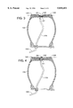
- FIGS. 5 and 6 are views of a further embodiment wherein a traction device is applied to a single wheel
- FIGS. 7 and 8 are views of a still further embodiment of a traction device as applied to a single wheel
- FIGS. 9 and 10 are views of another embodiment of a traction device applied to a single wheel.
- FIGS. 11-17 illustrate a wheel having a replaceable tread portion.
- FIGS. 1 and 2 of the drawings illustrate a traction device applied to a single wheel 100. Studs 20 are provided at spaced intervals along the center of the tread portion 102.
- the center tread portion 102 in combination with the tire wall 104 forms an expandable chamber 106 as shown in FIG. 2.
- a hose 108 connects the chamber 106 to a valve stem 110 (valve mechanism) to permit applying air pressure to the chamber 106 or relieving air pressure from the chamber 106.
- Air pressure is applied by a known air source, either remote or self contained on the vehicle.
- the chamber 106 is shown in the expanded state in FIG. 2 which forces the center tread portion 102 outwardly with reference to the wheel 100 to thus place the studs 20 into engagement with the ground surface.
- FIG. 1 shows the chamber 106 collapsed. That is, the air has been released from the chamber 106 and the natural resilience of the center tread portion 102 retracts the studs 20 inwardly toward the tire wall 104.
- FIGS. 3 and 4 illustrate another traction device applied to a wheel 120.
- a center tread portion 122 is provided between the side treads 124 and 126. Studs 20 are provided at spaced intervals along the center tread portion 122.
- the center tread portion 122 is expandable as shown in FIG. 4 and is contractible as shown in FIG. 3.
- the center tread portion 122 is expanded by the application of air pressure to a chamber 127 formed within the center tread portion 122 and is contractible by releasing the air from the chamber 127.
- a hose 128 couples the chamber 127 to a valve stem 130.
- the center tread portion 122 in the expanded state as is shown in FIG. 4 places the studs 20 in contact with the road surface to provided added traction.
- FIGS. 5 and 6 illustrate a traction device similar to those of FIGS. 1 and 2 except that in FIGS. 5 and 6 studs 20 are provided near each side edge 133 of the tire tread 132 on the wheel 121.
- An expandable chamber 134 is provided for each row of studs 20.
- a hose 136 couples each of the chambers 134 to a valve stem 138.
- the chambers 134 are expandable as shown in FIG. 6 and are contractible as shown in FIG. 5.
- the chambers 134 are expanded by applying air pressure to the chambers 134 and the chambers 134 are contracted by releasing the air from the chambers 134.
- the studs 20 are moved radially outward to contact the road surface.
- FIGS. 7 and 8 are similar to the traction devices of FIGS. 5 and 6 except that the chambers 134 are joined by a duct 142 provided in the tread 132 of the wheel 140. Preferably multiple ducts 142 are provided at spaced intervals along the length of the chambers 134. As shown in FIGS. 7 and 8, a single hose 146 is coupled to one of the chambers 134 and is connected to a valve stem 148. The chambers 134 are shown in the expanded state in FIG. 8 and are expanded by the application of air pressure. FIG. 7 illustrates the chambers 134 in the contracted or collapsed state and the chamber 134 is collapsed by releasing the air applied to the chamber 134.
- FIGS. 9 and 10 illustrate another traction device applied to a wheel 150.
- studs 20 are provided at spaced intervals in two rows around the periphery of the wheel 150.
- the studs 20 project from a tread portion 152 of the wheel 150.
- the wheel 150 has side tread sections 154 and 156 and a center tread section 158.
- Each of the tread sections 154, 156 and 158 have a chamber 160 that is expandable and contractible.
- a hose 162 connects the chambers 160 to a valve stem 164.
- the chambers 160 are collapsible as illustrated in FIG. 9 to place the studs 20 in contact with the road surface.
- the chambers 160 are expandable as shown in FIG. 10 with the tread sections 154, 156 and 158 being expanded beyond the height of the studs 20 to thus keep the studs 20 out of contact with the road surface.
- FIGS. 11 and 12 illustrate a traction device as applied to a single wheel 170.
- the wheel 170 has a tread 172.
- the tread 172 has channels 174 formed (see FIGS. 16 and 17) around its periphery with the channels 174 being of a depth to receive replaceable tubular section 176.
- the tubular section 176 is provided with studs 20.
- the tubular section 176 is removably mounted in the channels 174 provided in the tire tread 172.
- the profile of the channels 174 in the tread 172 will have a profile that matches the profile of the tubular section 176 (see FIG. 16).
- the tubular section has sufficient elasticity such that they may be installed and removed on the wheel 170 as required.
- the tubular section 176 with studs 20 would be installed on the wheel 170 when additional traction is required such as in ice or snowy conditions and the studs 20 will provide the added traction required.
- Each tubular portion 176 is inflatable (expandable) by pressurized air and as shown in FIGS. 11, 12, the tubular portion 176 has a stem 180 that extends through an aperture 171 into the cavity portion of the wheel 170.
- a coupler 182 connects the stems 180 to an air line 184.
- Air line 184 is connected to a conventional valve stem 186 for inflating and deflating the tubular portion 176.
- the tubular portion 176 is contractible by releasing the pressurized air.
- the tubular portion 176 is inflated by pressurized air so that the tubular portion 176 will be substantially even with the tread 172 of the wheel 170.
- the studs 20 will project beyond the tread 172 and the studs 20 of the tubular portion 176 thus will be in contact with the ground surface to provide additional traction.
- Tubular portion 178 is a filler unit that is most often utilized when additional traction afforded by the studs 20 is not required such as during the summer months.
- the tubular portion 178 when inflated (FIG. 14) will have its upper surface substantially even with the tread 172 of the wheel 170.
- the tubular portion 178 has a profile that will mate with the profile of the channel 174 (FIG. 17).
- the tubular portion 178 has a stem 180 that extends through the aperture 171 into the cavity portion of the wheel 170.
- a coupler 182 connects the stem 184 to an air line 184.
- Air line 184 is connected to a conventional valve stem 186 for inflating and deflating the tubular portion 178.
- FIG. 15 illustrates a tubular portion 178' that is removably mounted in the channel 174 of the wheel 170.
- the tubular portion 178' has a stem 181 that fits in the aperture 171 to provide a seal for the cavity of the wheel 170.
- the tubular portion 178' has sufficient elasticity to permit mounting the tubular portion 178' in the channel 174 formed in the tread 172. It will be appreciated that the tubular portions 178' may also be provided with studs 20.
Landscapes
- Engineering & Computer Science (AREA)
- Mechanical Engineering (AREA)
- Physics & Mathematics (AREA)
- Fluid Mechanics (AREA)
- Tires In General (AREA)
- Vehicle Body Suspensions (AREA)
- Manufacture Of Iron (AREA)
- Automatic Cycles, And Cycles In General (AREA)
- Lubricants (AREA)
Priority Applications (17)
| Application Number | Priority Date | Filing Date | Title |
|---|---|---|---|
| US08/909,302 US5810451A (en) | 1996-10-17 | 1997-08-11 | Traction device for vehicle wheels |
| CA002269071A CA2269071C (fr) | 1996-10-17 | 1997-10-17 | Dispositif d'adherence pour roues de vehicule |
| ES97911939T ES2264161T3 (es) | 1996-10-17 | 1997-10-17 | Dispositivo de traccion para ruedas de vehiculos. |
| AU49201/97A AU4920197A (en) | 1996-10-17 | 1997-10-17 | Traction device for vehicle wheels |
| PCT/US1997/019454 WO1998016399A1 (fr) | 1996-10-17 | 1997-10-17 | Dispositif d'adherence pour roues de vehicule |
| CA002591561A CA2591561A1 (fr) | 1996-10-17 | 1997-10-17 | Dispositif d'adherence pour roues de vehicule |
| DK97911939T DK0930980T3 (da) | 1996-10-17 | 1997-10-17 | Trækindretning til köretöjshjul |
| US09/284,557 US6386252B1 (en) | 1996-10-17 | 1997-10-17 | Traction device for vehicle wheels |
| PT97911939T PT930980E (pt) | 1996-10-17 | 1997-10-17 | Dispositivos de traccao para rodas de veiculos. |
| AT97911939T ATE324274T1 (de) | 1996-10-17 | 1997-10-17 | Zugvorrichtung für fahrzeugräder |
| EP97911939A EP0930980B1 (fr) | 1996-10-17 | 1997-10-17 | Dispositif d'adherence pour roues de vehicule |
| DE69735765T DE69735765T2 (de) | 1996-10-17 | 1997-10-17 | Zugvorrichtung für fahrzeugräder |
| JP51867098A JP2001524043A (ja) | 1996-10-17 | 1997-10-17 | 車両ホイール用のトラクション装置 |
| AU90151/98A AU9015198A (en) | 1997-08-11 | 1998-08-06 | Traction device for vehicle wheels |
| PCT/US1998/016384 WO1999007564A1 (fr) | 1997-08-11 | 1998-08-06 | Appareil de traction pour roues de vehicules |
| US09/497,310 US6244666B1 (en) | 1996-10-17 | 2000-02-03 | Traction device for vehicle wheels |
| US09/652,997 US6905564B1 (en) | 1996-10-17 | 2000-08-31 | Process for creating expandable tire chamber |
Applications Claiming Priority (2)
| Application Number | Priority Date | Filing Date | Title |
|---|---|---|---|
| US08/733,676 US5788335A (en) | 1996-10-17 | 1996-10-17 | Traction device for vehicle wheels |
| US08/909,302 US5810451A (en) | 1996-10-17 | 1997-08-11 | Traction device for vehicle wheels |
Related Parent Applications (3)
| Application Number | Title | Priority Date | Filing Date |
|---|---|---|---|
| US08/733,616 Continuation-In-Part US5926215A (en) | 1996-10-17 | 1996-10-17 | Fast readout of a color image sensor |
| US08/733,676 Continuation US5788335A (en) | 1996-10-17 | 1996-10-17 | Traction device for vehicle wheels |
| US08/733,676 Continuation-In-Part US5788335A (en) | 1996-10-17 | 1996-10-17 | Traction device for vehicle wheels |
Related Child Applications (4)
| Application Number | Title | Priority Date | Filing Date |
|---|---|---|---|
| US08/733,676 Continuation-In-Part US5788335A (en) | 1996-10-17 | 1996-10-17 | Traction device for vehicle wheels |
| US09284557 Continuation-In-Part | 1997-10-17 | ||
| US09/284,557 Continuation US6386252B1 (en) | 1996-10-17 | 1997-10-17 | Traction device for vehicle wheels |
| PCT/US1997/019454 Continuation-In-Part WO1998016399A1 (fr) | 1996-10-17 | 1997-10-17 | Dispositif d'adherence pour roues de vehicule |
Publications (1)
| Publication Number | Publication Date |
|---|---|
| US5810451A true US5810451A (en) | 1998-09-22 |
Family
ID=27112611
Family Applications (3)
| Application Number | Title | Priority Date | Filing Date |
|---|---|---|---|
| US08/909,302 Expired - Lifetime US5810451A (en) | 1996-10-17 | 1997-08-11 | Traction device for vehicle wheels |
| US09/284,557 Expired - Fee Related US6386252B1 (en) | 1996-10-17 | 1997-10-17 | Traction device for vehicle wheels |
| US09/497,310 Expired - Fee Related US6244666B1 (en) | 1996-10-17 | 2000-02-03 | Traction device for vehicle wheels |
Family Applications After (2)
| Application Number | Title | Priority Date | Filing Date |
|---|---|---|---|
| US09/284,557 Expired - Fee Related US6386252B1 (en) | 1996-10-17 | 1997-10-17 | Traction device for vehicle wheels |
| US09/497,310 Expired - Fee Related US6244666B1 (en) | 1996-10-17 | 2000-02-03 | Traction device for vehicle wheels |
Country Status (11)
| Country | Link |
|---|---|
| US (3) | US5810451A (fr) |
| EP (1) | EP0930980B1 (fr) |
| JP (1) | JP2001524043A (fr) |
| AT (1) | ATE324274T1 (fr) |
| AU (1) | AU4920197A (fr) |
| CA (1) | CA2269071C (fr) |
| DE (1) | DE69735765T2 (fr) |
| DK (1) | DK0930980T3 (fr) |
| ES (1) | ES2264161T3 (fr) |
| PT (1) | PT930980E (fr) |
| WO (1) | WO1998016399A1 (fr) |
Cited By (24)
| Publication number | Priority date | Publication date | Assignee | Title |
|---|---|---|---|---|
| EP0909666A2 (fr) * | 1997-09-16 | 1999-04-21 | Kinzo Hatta | Bandage pneumatique à propriétés anti-dérapantes |
| US6022082A (en) * | 1996-10-17 | 2000-02-08 | Traction On Demand Llc | Traction device for vehicle wheels |
| US6244666B1 (en) * | 1996-10-17 | 2001-06-12 | Power Cleat, Ltd. | Traction device for vehicle wheels |
| US20030071513A1 (en) * | 2001-10-15 | 2003-04-17 | Elkow Douglas B. | Variable-diameter wheel-and-tire apparatus for motor vehicles |
| US6581661B1 (en) | 1999-07-10 | 2003-06-24 | Large Car Equipment And Apparel, Llc | Apparatus for improving tire traction |
| US6637834B2 (en) | 2001-10-15 | 2003-10-28 | Douglas B. Elkow | Variable-diameter wheel apparatus for motor vehicles |
| US20040206436A1 (en) * | 2003-02-18 | 2004-10-21 | Clay Ferguson | Automobile traction devices |
| US20050092411A1 (en) * | 2003-10-31 | 2005-05-05 | O'brien John M. | Tire having expandable tread portion |
| US6905564B1 (en) * | 1996-10-17 | 2005-06-14 | Power Cleat, Ltd. | Process for creating expandable tire chamber |
| US20060174518A1 (en) * | 2005-02-07 | 2006-08-10 | Fogarty Stacy R | Convertible traction shoes |
| US20060213593A1 (en) * | 2005-03-24 | 2006-09-28 | O'brien John M | Safety tire, method of making and method of improved traffic safety with use thereof |
| US20080047645A1 (en) * | 2006-08-24 | 2008-02-28 | Jon Stuart Gerhardt | tractive tire method and apparatus |
| US20080066348A1 (en) * | 2005-02-07 | 2008-03-20 | Select Sole, Llc | Footwear with retractable members |
| US20080190531A1 (en) * | 2007-02-09 | 2008-08-14 | Mabra Holeyfield | Snow and Ice Patch For Tires |
| US20090165912A1 (en) * | 2007-12-31 | 2009-07-02 | Jean Joseph Victor Collette | Tire with retractable stud |
| CN101007492B (zh) * | 2006-01-27 | 2010-05-12 | 蓝进 | 安全轮胎及制造方法和使用该轮胎提高交通安全性的方法 |
| US20110151040A1 (en) * | 2009-12-17 | 2011-06-23 | Cuny Andre | Mold apparatus for forming grooves in tire shoulder |
| US20140116592A1 (en) * | 2011-10-31 | 2014-05-01 | Innovative Technologies, Llc | All-weather Tire |
| US9045013B2 (en) | 2012-08-20 | 2015-06-02 | Ice Adaptive Tires, LLC. | Ice adaptive tire system |
| US9290057B2 (en) | 2011-10-31 | 2016-03-22 | Innovative Technologies, Llc | All season safety tire |
| US9744804B2 (en) | 2010-09-27 | 2017-08-29 | Kendall W Pope | Multi-diameter tire and wheel assembly for improved vehicle mileage with passive transfer between tire diameters |
| US9855800B2 (en) * | 2016-02-22 | 2018-01-02 | The Goodyear Tire & Rubber Company | Tripletube tire |
| PL425275A1 (pl) * | 2018-04-19 | 2019-10-21 | Rybka Piotr P.P.H.U. Rybka-Globgum 3 | Opona samochodowa do jazdy ćwiczebnej oraz sposób wykonania bieżnika do tej opony |
| US11310952B2 (en) * | 2018-10-12 | 2022-04-26 | Otico | Self-cleaning agriculture roller |
Families Citing this family (21)
| Publication number | Priority date | Publication date | Assignee | Title |
|---|---|---|---|---|
| WO2004005048A1 (fr) * | 2002-07-08 | 2004-01-15 | John Maltzahn | Vehicule tout-terrain |
| SE524746C2 (sv) * | 2003-02-13 | 2004-09-28 | Sven A Jansson | Fordonshjul |
| US7252728B2 (en) * | 2004-07-12 | 2007-08-07 | The Goodyear Tire & Rubber Company | Method for forming a pneumatic tire |
| KR100738649B1 (ko) | 2005-03-23 | 2007-07-11 | 금호타이어 주식회사 | 주행성능이 향상된 공기입 타이어 |
| FR2885844B1 (fr) * | 2005-05-17 | 2007-07-27 | Philippe Biesse | Jante anti-enlisement |
| JP3123417U (ja) * | 2006-05-02 | 2006-07-20 | 株式会社アイメック | トラックローダー型車輌の防振装置 |
| US7784196B1 (en) * | 2006-12-13 | 2010-08-31 | Reebok International Ltd. | Article of footwear having an inflatable ground engaging surface |
| US20090114322A1 (en) * | 2007-11-06 | 2009-05-07 | O'brien Pat | Tread marker, tire with integral tread markers, and methods for producing both |
| CZ303947B6 (cs) | 2010-09-14 | 2013-07-10 | Technická univerzita v Liberci | Pojezdové kolo vozidla |
| US20130153082A1 (en) * | 2011-12-14 | 2013-06-20 | International Business Machines Corporation | Variable friction tires |
| CN102555665A (zh) * | 2012-02-16 | 2012-07-11 | 杜增辉 | 汽车冬季行车防滑方法及所用充气式外置防滑车轮 |
| JP6007592B2 (ja) * | 2012-05-22 | 2016-10-12 | 横浜ゴム株式会社 | タイヤ・ホイール組立体および電動車両 |
| CZ24299U1 (cs) | 2012-07-09 | 2012-09-10 | Gross@Petr | Protiskluzové zarízení pro kola automobilu |
| ES2423083B1 (es) * | 2013-05-16 | 2014-09-02 | Seat, S.A. | Sistema de desinflado automático de los neumáticos de un vehículo automóvil, y neumático de doble cámara para el mismo |
| AT513181B1 (de) | 2013-11-12 | 2015-02-15 | Würkner Gerald Ing Mag | Vorrichtung zur Verbesserung der Haftung eines Fahrzeugreifens |
| KR102137829B1 (ko) * | 2014-10-06 | 2020-07-27 | 현대자동차주식회사 | 가변형 타이어 |
| KR101732427B1 (ko) | 2016-03-07 | 2017-05-24 | 김종태 | 대형구조물 이동차량용 보조바퀴 장착장치 |
| KR102351638B1 (ko) * | 2017-09-04 | 2022-01-17 | 현대건설기계 주식회사 | 더블타이어 보호장비, 이를 구비하는 더블타이어 및 이를 포함하는 이동수단 |
| CN108284705B (zh) * | 2018-01-25 | 2024-05-10 | 安徽港泰机械制造集团有限公司 | 一种使用寿命长的便捷型公路铁路两用车轮 |
| US11458761B2 (en) * | 2019-10-01 | 2022-10-04 | Joe Cindrich | Traction system for vehicle |
| WO2023061518A1 (fr) * | 2021-10-14 | 2023-04-20 | Technicka Univerzita V Liberci | Roue de véhicule adaptative |
Citations (22)
| Publication number | Priority date | Publication date | Assignee | Title |
|---|---|---|---|---|
| FR723612A (fr) * | 1931-09-10 | 1932-04-12 | Roue de sûreté à bandages pneumatiques pour automobiles ou autres véhicules analogues | |
| US2079501A (en) * | 1935-10-19 | 1937-05-04 | Gerald R Gallagher | Antiskid device |
| US2174944A (en) * | 1937-11-16 | 1939-10-03 | Rae H Leggett | Vehicle wheel traction means |
| US2201632A (en) * | 1937-09-15 | 1940-05-21 | Elmon C Gillette | Antiskidding device for automobiles |
| US2241849A (en) * | 1940-02-07 | 1941-05-13 | Arthur S Kee | Nonskid mechanism for dual wheels |
| US2254318A (en) * | 1939-02-04 | 1941-09-02 | Louis Otto E Roessel | Traction device |
| US2377923A (en) * | 1938-12-22 | 1945-06-12 | Aloysius J Cawley | Road engaging means for automobiles or the like |
| US2559721A (en) * | 1950-05-16 | 1951-07-10 | John J Kruse | Ice gripper for vehicle wheels |
| FR1006702A (fr) * | 1947-08-19 | 1952-04-28 | Geigy Ag J R | Procédé de préparation de dérivés d'éthylène-diamines |
| US2638384A (en) * | 1949-05-23 | 1953-05-12 | Colin Louis | Retractable strake device |
| US2751959A (en) * | 1953-06-11 | 1956-06-26 | Fairchild Engine And Aiplane C | Vehicle wheel |
| US2765199A (en) * | 1956-02-17 | 1956-10-02 | Earl E Partin | Anti-skid wheel assembly |
| AT198148B (de) * | 1957-04-24 | 1958-06-10 | Wenzel Schlifelner | Gleitschutzvorrichtung für Kraftfahrzeuge |
| US2903037A (en) * | 1958-03-17 | 1959-09-08 | Fred L Palmer | Traction attachment for wheels |
| US3995909A (en) * | 1974-01-15 | 1976-12-07 | Lely Cornelis V D | Vehicle anti-skid mechanisms |
| DE2901606A1 (de) * | 1979-01-17 | 1980-07-31 | Schmitt Baugeraetevermittlung | Vorrichtung zum freihalten des zwischenraums von zwillingsreifen |
| DE3001483A1 (de) * | 1980-01-17 | 1981-07-23 | Dietmar 2071 Hamfelde Heidemann | Zusatzbereifung mit gleitschutzvorrichtung |
| FR2556656A1 (fr) * | 1983-12-14 | 1985-06-21 | Amara Mohand | Accessoire automobile de securite anti-crevaison, anti-blocage de roues, anti-derapage |
| US4676289A (en) * | 1984-08-13 | 1987-06-30 | Cherng Yi Su | Automobile tire having retractable tread studs |
| EP0236041A2 (fr) * | 1986-02-25 | 1987-09-09 | Kabushiki Kaisha Tohdoh Koumuten | Dispositif anti-dérapant à spikes pour véhicules automobiles et son mécanisme de contrôle |
| US5411070A (en) * | 1990-04-05 | 1995-05-02 | Yadegar; Iraj | Self-contained anti-skid device for pneumatic tires |
| US5609700A (en) * | 1993-11-06 | 1997-03-11 | West; Allen D. | Operator selectable "on demand" studded tire |
Family Cites Families (39)
| Publication number | Priority date | Publication date | Assignee | Title |
|---|---|---|---|---|
| FR1066702A (fr) * | 1954-06-09 | |||
| FR659277A (fr) | 1928-02-17 | 1929-06-26 | Procédé de redressement des courants électriques polyphasés | |
| US1749766A (en) | 1928-08-11 | 1930-03-11 | Hitchner Tire Corp | Tire |
| US2480548A (en) | 1948-08-02 | 1949-08-30 | William H Carhart | Vehicle tire |
| US2708470A (en) | 1952-02-20 | 1955-05-17 | Clarence U Gramelspacher | Tire construction |
| US2835302A (en) | 1955-12-30 | 1958-05-20 | Gedge Thomas James | Adjustable pneumatic tire |
| US2926720A (en) | 1957-08-02 | 1960-03-01 | Gosman Clarence Berveir | Method of and apparatus for making inflatable articles |
| US3110339A (en) | 1962-01-02 | 1963-11-12 | Lawrence K Fickel | Ventilated pneumatic tire structure and method of fabricating the tire |
| CH504318A (it) * | 1970-01-08 | 1971-03-15 | Cadlini Alberto | Pneumatico con battistrada trasformabile immediatamente da estivo a invernale e viceversa |
| US3942572A (en) | 1974-01-15 | 1976-03-09 | Crandall Azel L | Multicelled, tubeless safety tire with air activated snow and ice studs |
| US4293017A (en) | 1977-12-01 | 1981-10-06 | Lambe Donald M | Dual-chamber pneumatic tire |
| US5109905A (en) | 1977-12-01 | 1992-05-05 | Lambe Donald M | Dual chamber pneumatic tire with the chambers separated by a collapsible partition wall |
| JPS58122207A (ja) | 1982-01-12 | 1983-07-20 | Kinya Nakamura | 空転止め出没タイヤ |
| JPS59114103A (ja) | 1982-12-17 | 1984-07-02 | Kinya Nakamura | 滑り止め出没タイヤ |
| JPS59164208A (ja) * | 1983-03-04 | 1984-09-17 | Hiroyuki Ito | スパイクタイヤ |
| US4909972A (en) | 1985-12-02 | 1990-03-20 | Britz Johannes H | Method and apparatus for making a solid foamed tire core |
| US4803029A (en) | 1986-01-28 | 1989-02-07 | Pmt Corporation | Process for manufacturing an expandable member |
| JPS62299408A (ja) | 1986-06-17 | 1987-12-26 | Masashi Kumano | 空気圧によりなるスパイクタイヤ |
| JPS6343804A (ja) * | 1986-08-09 | 1988-02-24 | Natsuo Suzuki | 空気の操作でスパイクを出し入れして車粉の発生を防止するスパイクラジアルタイヤ |
| JPS6368408A (ja) | 1986-09-09 | 1988-03-28 | Kiyohiro Hirakawa | 滑り止めタイヤ装置 |
| FR2607757B1 (fr) | 1986-12-04 | 1991-05-31 | Peugeot | Dispositif de suspension de la caisse et du groupe motopropulseur d'un vehicule automobile |
| JPS63145109A (ja) | 1986-12-05 | 1988-06-17 | Mitsuya Ooba | 可変式スパイク・スノ−タイヤ |
| DE3721500A1 (de) | 1987-06-30 | 1989-01-12 | Agot Eric Joel | Einziehbares-integriertes-reifenspikessystem (eir-system) |
| JPH01122708A (ja) | 1987-11-07 | 1989-05-16 | Teruo Iwama | 手動操作による自在使用スパイクタイヤ |
| DE3800326A1 (de) | 1988-01-08 | 1989-07-20 | Reinhold Kuhn | Kraftfahrzeug-kombireifen |
| EP0418974A1 (fr) | 1989-09-19 | 1991-03-27 | Union Carbide Chemicals And Plastics Company, Inc. | Catalyseurs contenant de l'argent, pour des procédés de couplage oxydatif |
| JPH07102762B2 (ja) | 1989-11-27 | 1995-11-08 | 武昭 永井 | 自動車用タイヤ |
| FR2659277A1 (fr) | 1990-03-09 | 1991-09-13 | Landreau Francois | Dispositif escamotable pour un pneumatique cloute, notamment pour l'automobile. |
| DE4207613A1 (de) | 1992-03-10 | 1993-09-16 | Hans Scheibenpflug | Spikesreifen |
| JPH0632111U (ja) | 1992-10-07 | 1994-04-26 | 藤一 竹林 | タイヤの構造 |
| US5419726A (en) | 1993-12-17 | 1995-05-30 | Switlik Parachute Company, Inc. | Inflatable flotation raft apparatus having heated seal areas and method of assembly thereof |
| JPH07276926A (ja) | 1994-04-02 | 1995-10-24 | Shigeru Kato | スパイク付きタイヤ |
| JPH07309107A (ja) | 1994-05-16 | 1995-11-28 | Shigeru Kato | スパイク付きタイヤ |
| JPH08310204A (ja) | 1995-05-18 | 1996-11-26 | Takatoshi Aoyama | タイヤ |
| DE29601450U1 (de) * | 1996-01-29 | 1996-03-07 | Seifert, Adelheid, 87779 Trunkelsberg | Gleitschutz für Kraftfahrzeuge |
| US5795414A (en) | 1996-04-10 | 1998-08-18 | Shih; Choon J. | Puncture resistant tire assembly |
| US5810451A (en) * | 1996-10-17 | 1998-09-22 | O'brien; John Michael | Traction device for vehicle wheels |
| US5788335A (en) * | 1996-10-17 | 1998-08-04 | O'brien; John M. | Traction device for vehicle wheels |
| DE69824512D1 (de) * | 1997-09-16 | 2004-07-22 | Kinzo Hatta | Reifen mit Gleitschutzeigenschaften |
-
1997
- 1997-08-11 US US08/909,302 patent/US5810451A/en not_active Expired - Lifetime
- 1997-10-17 WO PCT/US1997/019454 patent/WO1998016399A1/fr active IP Right Grant
- 1997-10-17 DK DK97911939T patent/DK0930980T3/da active
- 1997-10-17 US US09/284,557 patent/US6386252B1/en not_active Expired - Fee Related
- 1997-10-17 ES ES97911939T patent/ES2264161T3/es not_active Expired - Lifetime
- 1997-10-17 AU AU49201/97A patent/AU4920197A/en not_active Abandoned
- 1997-10-17 CA CA002269071A patent/CA2269071C/fr not_active Expired - Fee Related
- 1997-10-17 JP JP51867098A patent/JP2001524043A/ja active Pending
- 1997-10-17 EP EP97911939A patent/EP0930980B1/fr not_active Expired - Lifetime
- 1997-10-17 PT PT97911939T patent/PT930980E/pt unknown
- 1997-10-17 AT AT97911939T patent/ATE324274T1/de not_active IP Right Cessation
- 1997-10-17 DE DE69735765T patent/DE69735765T2/de not_active Expired - Fee Related
-
2000
- 2000-02-03 US US09/497,310 patent/US6244666B1/en not_active Expired - Fee Related
Patent Citations (22)
| Publication number | Priority date | Publication date | Assignee | Title |
|---|---|---|---|---|
| FR723612A (fr) * | 1931-09-10 | 1932-04-12 | Roue de sûreté à bandages pneumatiques pour automobiles ou autres véhicules analogues | |
| US2079501A (en) * | 1935-10-19 | 1937-05-04 | Gerald R Gallagher | Antiskid device |
| US2201632A (en) * | 1937-09-15 | 1940-05-21 | Elmon C Gillette | Antiskidding device for automobiles |
| US2174944A (en) * | 1937-11-16 | 1939-10-03 | Rae H Leggett | Vehicle wheel traction means |
| US2377923A (en) * | 1938-12-22 | 1945-06-12 | Aloysius J Cawley | Road engaging means for automobiles or the like |
| US2254318A (en) * | 1939-02-04 | 1941-09-02 | Louis Otto E Roessel | Traction device |
| US2241849A (en) * | 1940-02-07 | 1941-05-13 | Arthur S Kee | Nonskid mechanism for dual wheels |
| FR1006702A (fr) * | 1947-08-19 | 1952-04-28 | Geigy Ag J R | Procédé de préparation de dérivés d'éthylène-diamines |
| US2638384A (en) * | 1949-05-23 | 1953-05-12 | Colin Louis | Retractable strake device |
| US2559721A (en) * | 1950-05-16 | 1951-07-10 | John J Kruse | Ice gripper for vehicle wheels |
| US2751959A (en) * | 1953-06-11 | 1956-06-26 | Fairchild Engine And Aiplane C | Vehicle wheel |
| US2765199A (en) * | 1956-02-17 | 1956-10-02 | Earl E Partin | Anti-skid wheel assembly |
| AT198148B (de) * | 1957-04-24 | 1958-06-10 | Wenzel Schlifelner | Gleitschutzvorrichtung für Kraftfahrzeuge |
| US2903037A (en) * | 1958-03-17 | 1959-09-08 | Fred L Palmer | Traction attachment for wheels |
| US3995909A (en) * | 1974-01-15 | 1976-12-07 | Lely Cornelis V D | Vehicle anti-skid mechanisms |
| DE2901606A1 (de) * | 1979-01-17 | 1980-07-31 | Schmitt Baugeraetevermittlung | Vorrichtung zum freihalten des zwischenraums von zwillingsreifen |
| DE3001483A1 (de) * | 1980-01-17 | 1981-07-23 | Dietmar 2071 Hamfelde Heidemann | Zusatzbereifung mit gleitschutzvorrichtung |
| FR2556656A1 (fr) * | 1983-12-14 | 1985-06-21 | Amara Mohand | Accessoire automobile de securite anti-crevaison, anti-blocage de roues, anti-derapage |
| US4676289A (en) * | 1984-08-13 | 1987-06-30 | Cherng Yi Su | Automobile tire having retractable tread studs |
| EP0236041A2 (fr) * | 1986-02-25 | 1987-09-09 | Kabushiki Kaisha Tohdoh Koumuten | Dispositif anti-dérapant à spikes pour véhicules automobiles et son mécanisme de contrôle |
| US5411070A (en) * | 1990-04-05 | 1995-05-02 | Yadegar; Iraj | Self-contained anti-skid device for pneumatic tires |
| US5609700A (en) * | 1993-11-06 | 1997-03-11 | West; Allen D. | Operator selectable "on demand" studded tire |
Cited By (53)
| Publication number | Priority date | Publication date | Assignee | Title |
|---|---|---|---|---|
| US6022082A (en) * | 1996-10-17 | 2000-02-08 | Traction On Demand Llc | Traction device for vehicle wheels |
| US6244666B1 (en) * | 1996-10-17 | 2001-06-12 | Power Cleat, Ltd. | Traction device for vehicle wheels |
| US6386252B1 (en) * | 1996-10-17 | 2002-05-14 | Power Cleat Ltd. | Traction device for vehicle wheels |
| US6905564B1 (en) * | 1996-10-17 | 2005-06-14 | Power Cleat, Ltd. | Process for creating expandable tire chamber |
| EP0909666A2 (fr) * | 1997-09-16 | 1999-04-21 | Kinzo Hatta | Bandage pneumatique à propriétés anti-dérapantes |
| US6092576A (en) * | 1997-09-16 | 2000-07-25 | Hatta; Kinzo | Tire having anti-slip properties |
| EP0909666A3 (fr) * | 1997-09-16 | 2000-10-18 | Kinzo Hatta | Bandage pneumatique à propriétés anti-dérapantes |
| US6581661B1 (en) | 1999-07-10 | 2003-06-24 | Large Car Equipment And Apparel, Llc | Apparatus for improving tire traction |
| US6615888B2 (en) * | 2001-10-15 | 2003-09-09 | Douglas B. Elkow | Variable-diameter wheel-and-tire apparatus for motor vehicles |
| US6637834B2 (en) | 2001-10-15 | 2003-10-28 | Douglas B. Elkow | Variable-diameter wheel apparatus for motor vehicles |
| US20040036347A1 (en) * | 2001-10-15 | 2004-02-26 | Elkow Douglas B. | Variable-diameter wheel apparatus for motor vehicles |
| US6733088B2 (en) * | 2001-10-15 | 2004-05-11 | Douglas B. Elkow | Variable-diameter wheel apparatus for motor vehicles |
| WO2003033276A1 (fr) | 2001-10-15 | 2003-04-24 | Elkow Douglas B | Dispositif roue et pneu a diametre variable conçu pour vehicules automobiles |
| US20030071513A1 (en) * | 2001-10-15 | 2003-04-17 | Elkow Douglas B. | Variable-diameter wheel-and-tire apparatus for motor vehicles |
| US6918544B2 (en) * | 2003-02-18 | 2005-07-19 | Clay Ferguson | Automobile traction devices |
| US20040206436A1 (en) * | 2003-02-18 | 2004-10-21 | Clay Ferguson | Automobile traction devices |
| US20050092411A1 (en) * | 2003-10-31 | 2005-05-05 | O'brien John M. | Tire having expandable tread portion |
| US20060191615A1 (en) * | 2003-10-31 | 2006-08-31 | O'brien John M | Tire having expandable tread portion |
| WO2005044591A3 (fr) * | 2003-10-31 | 2006-02-23 | Power Cleat Inc | Pneumatique ayant une partie bande de roulement expansible |
| US7913425B2 (en) | 2005-02-07 | 2011-03-29 | Select Sole, Llc | Convertible traction shoes |
| US20060174518A1 (en) * | 2005-02-07 | 2006-08-10 | Fogarty Stacy R | Convertible traction shoes |
| US7234250B2 (en) | 2005-02-07 | 2007-06-26 | Stacy Renee Fogarty | Convertible traction shoes |
| US20100024250A1 (en) * | 2005-02-07 | 2010-02-04 | Select Sole, Llc | Convertible traction shoes |
| US20080066348A1 (en) * | 2005-02-07 | 2008-03-20 | Select Sole, Llc | Footwear with retractable members |
| US20080010859A1 (en) * | 2005-02-07 | 2008-01-17 | Fogarty Stacy R | Convertible traction shoes |
| US7584554B2 (en) | 2005-02-07 | 2009-09-08 | Select Sole, Llc | Convertible traction shoes |
| US20060213593A1 (en) * | 2005-03-24 | 2006-09-28 | O'brien John M | Safety tire, method of making and method of improved traffic safety with use thereof |
| US7291237B2 (en) | 2005-03-24 | 2007-11-06 | O'brien John Michael | Method of making tire having wear indicators |
| WO2006102468A3 (fr) * | 2005-03-24 | 2007-10-25 | John Michael O'brien | Pneumatique de securite, procede de fabrication et procede pour securite routiere amelioree a l'aide dudit pneumatique |
| CN101007492B (zh) * | 2006-01-27 | 2010-05-12 | 蓝进 | 安全轮胎及制造方法和使用该轮胎提高交通安全性的方法 |
| US20080047645A1 (en) * | 2006-08-24 | 2008-02-28 | Jon Stuart Gerhardt | tractive tire method and apparatus |
| WO2008024656A3 (fr) * | 2006-08-24 | 2008-09-04 | Tires Inc Q | Appareil et procédé de pneu de traction |
| WO2008024656A2 (fr) * | 2006-08-24 | 2008-02-28 | Q Tires, Inc. | Appareil et procédé de pneu de traction |
| US20080190531A1 (en) * | 2007-02-09 | 2008-08-14 | Mabra Holeyfield | Snow and Ice Patch For Tires |
| US8082961B2 (en) | 2007-12-31 | 2011-12-27 | The Goodyear Tire & Rubber Company | Tire with retractable stud |
| US20090165912A1 (en) * | 2007-12-31 | 2009-07-02 | Jean Joseph Victor Collette | Tire with retractable stud |
| US8186985B2 (en) | 2009-12-17 | 2012-05-29 | The Goodyear Tire & Rubber Company | Mold apparatus for forming grooves in tire shoulder |
| US20110151040A1 (en) * | 2009-12-17 | 2011-06-23 | Cuny Andre | Mold apparatus for forming grooves in tire shoulder |
| US9744804B2 (en) | 2010-09-27 | 2017-08-29 | Kendall W Pope | Multi-diameter tire and wheel assembly for improved vehicle mileage with passive transfer between tire diameters |
| US20140116592A1 (en) * | 2011-10-31 | 2014-05-01 | Innovative Technologies, Llc | All-weather Tire |
| US10576792B2 (en) * | 2011-10-31 | 2020-03-03 | Innovative Technologies, Llc | All-weather tire |
| US10576796B2 (en) * | 2011-10-31 | 2020-03-03 | Innovative Technologies, Llc | All season safety tire |
| US9278584B2 (en) * | 2011-10-31 | 2016-03-08 | Innovative Technologies, Llc | All-weather tire |
| US9290057B2 (en) | 2011-10-31 | 2016-03-22 | Innovative Technologies, Llc | All season safety tire |
| US20160167445A1 (en) * | 2011-10-31 | 2016-06-16 | Innovative Technologies, Llc | All-weather tire |
| US20160200152A1 (en) * | 2011-10-31 | 2016-07-14 | Innovative Technologies, Llc | All season safety tire |
| US9205713B2 (en) | 2012-08-20 | 2015-12-08 | Ice Adaptive Tires, LLC | Bolt assembly providing reciprocating bolt and associated method |
| US9409455B2 (en) | 2012-08-20 | 2016-08-09 | Ice Adaptive Tires, LLC | Selectably engaged rotary union |
| US9150060B2 (en) | 2012-08-20 | 2015-10-06 | Ice Adaptive Tires, LLC | Wheel suitable for use with an ice adaptive tire |
| US9045013B2 (en) | 2012-08-20 | 2015-06-02 | Ice Adaptive Tires, LLC. | Ice adaptive tire system |
| US9855800B2 (en) * | 2016-02-22 | 2018-01-02 | The Goodyear Tire & Rubber Company | Tripletube tire |
| PL425275A1 (pl) * | 2018-04-19 | 2019-10-21 | Rybka Piotr P.P.H.U. Rybka-Globgum 3 | Opona samochodowa do jazdy ćwiczebnej oraz sposób wykonania bieżnika do tej opony |
| US11310952B2 (en) * | 2018-10-12 | 2022-04-26 | Otico | Self-cleaning agriculture roller |
Also Published As
| Publication number | Publication date |
|---|---|
| PT930980E (pt) | 2006-08-31 |
| JP2001524043A (ja) | 2001-11-27 |
| ATE324274T1 (de) | 2006-05-15 |
| ES2264161T3 (es) | 2006-12-16 |
| CA2269071A1 (fr) | 1998-04-23 |
| US6244666B1 (en) | 2001-06-12 |
| EP0930980B1 (fr) | 2006-04-26 |
| CA2269071C (fr) | 2009-01-27 |
| DE69735765D1 (de) | 2006-06-01 |
| DK0930980T3 (da) | 2006-07-31 |
| WO1998016399A1 (fr) | 1998-04-23 |
| EP0930980A1 (fr) | 1999-07-28 |
| AU4920197A (en) | 1998-05-11 |
| US6386252B1 (en) | 2002-05-14 |
| EP0930980A4 (fr) | 2002-10-02 |
| DE69735765T2 (de) | 2006-11-02 |
Similar Documents
| Publication | Publication Date | Title |
|---|---|---|
| US5810451A (en) | Traction device for vehicle wheels | |
| US5788335A (en) | Traction device for vehicle wheels | |
| US6022082A (en) | Traction device for vehicle wheels | |
| US6044883A (en) | Retractable anti-skid tread for dual tire vehicles | |
| US4676289A (en) | Automobile tire having retractable tread studs | |
| US3942572A (en) | Multicelled, tubeless safety tire with air activated snow and ice studs | |
| US7448421B2 (en) | Safety traction device | |
| US4059138A (en) | Run-flat tire and hub therefor | |
| US2491491A (en) | Pneumatic tire and antiskid means therefor | |
| US2898965A (en) | Auxiliary tread for dual wheels | |
| US20070079915A1 (en) | Cluster trac 4 season radial technical field | |
| US20130300185A1 (en) | Mobility device and method | |
| US5609700A (en) | Operator selectable "on demand" studded tire | |
| US3340921A (en) | Pneumatic anti-skid vehicle tires | |
| US3516466A (en) | Spiked tires for automotive vehicles | |
| US3963066A (en) | Reversible replaceable tread tire | |
| US2650632A (en) | Adjustable tire | |
| WO1999007564A1 (fr) | Appareil de traction pour roues de vehicules | |
| US3506051A (en) | Traction-increasing device | |
| CA2591561A1 (fr) | Dispositif d'adherence pour roues de vehicule | |
| CN211166232U (zh) | 具有防滑性能的轮胎 | |
| KR100286420B1 (ko) | 튜브레스 타이어의 스노우 스파이크장치 | |
| US1331575A (en) | Vehicle-wheel | |
| FR2659277A1 (fr) | Dispositif escamotable pour un pneumatique cloute, notamment pour l'automobile. | |
| KR200168922Y1 (ko) | 공기압의 조절에 의해 스파이크가 돌출 및 삽입되는 타이어 |
Legal Events
| Date | Code | Title | Description |
|---|---|---|---|
| STCF | Information on status: patent grant |
Free format text: PATENTED CASE |
|
| AS | Assignment |
Owner name: POWER CLEAT LTD., NEVADA Free format text: ASSIGNMENT OF ASSIGNORS INTEREST;ASSIGNOR:O'BRIEN, JOHN MICHAEL;REEL/FRAME:011084/0269 Effective date: 20000823 |
|
| AS | Assignment |
Owner name: POWER CLEAT LTD., NEVADA Free format text: RE-RECORD TO CORRECT THE STATE OF INCORPORATION OF THE ASSIGNEE, PREVIOUSLY RECORDED ON REEL 011084 FRAME 0269, ASSIGNOR CONFIRMS THE ASSIGNMENT THE ENTIRE INTEREST.;ASSIGNOR:O'BRIEN, JOHN MICHAEL;REEL/FRAME:011347/0345 Effective date: 20001127 |
|
| FPAY | Fee payment |
Year of fee payment: 4 |
|
| REMI | Maintenance fee reminder mailed | ||
| FPAY | Fee payment |
Year of fee payment: 8 |
|
| SULP | Surcharge for late payment |
Year of fee payment: 7 |
|
| AS | Assignment |
Owner name: Q TIRES, INC., OREGON Free format text: CHANGE OF NAME;ASSIGNOR:POWER CLEAT, INC.;REEL/FRAME:018891/0449 Effective date: 20050214 Owner name: POWER CLEAT, INC., OREGON Free format text: CHANGE OF NAME;ASSIGNOR:POWER CLEAT LTD.;REEL/FRAME:018891/0446 Effective date: 20030424 |
|
| REMI | Maintenance fee reminder mailed | ||
| FPAY | Fee payment |
Year of fee payment: 12 |
|
| SULP | Surcharge for late payment |
Year of fee payment: 11 |