US5522282A - Connecting structure between bicycle pedal and cleat, bicycle pedal and cleat - Google Patents
Connecting structure between bicycle pedal and cleat, bicycle pedal and cleat Download PDFInfo
- Publication number
- US5522282A US5522282A US07/971,269 US97126992A US5522282A US 5522282 A US5522282 A US 5522282A US 97126992 A US97126992 A US 97126992A US 5522282 A US5522282 A US 5522282A
- Authority
- US
- United States
- Prior art keywords
- cleat
- pedal
- axis
- hook
- hooks
- Prior art date
- Legal status (The legal status is an assumption and is not a legal conclusion. Google has not performed a legal analysis and makes no representation as to the accuracy of the status listed.)
- Expired - Lifetime
Links
Images


Classifications
-
- B—PERFORMING OPERATIONS; TRANSPORTING
- B62—LAND VEHICLES FOR TRAVELLING OTHERWISE THAN ON RAILS
- B62M—RIDER PROPULSION OF WHEELED VEHICLES OR SLEDGES; POWERED PROPULSION OF SLEDGES OR SINGLE-TRACK CYCLES; TRANSMISSIONS SPECIALLY ADAPTED FOR SUCH VEHICLES
- B62M3/00—Construction of cranks operated by hand or foot
- B62M3/08—Pedals
- B62M3/086—Attachments between shoe and pedal other than toe clips, e.g. cleats
-
- Y—GENERAL TAGGING OF NEW TECHNOLOGICAL DEVELOPMENTS; GENERAL TAGGING OF CROSS-SECTIONAL TECHNOLOGIES SPANNING OVER SEVERAL SECTIONS OF THE IPC; TECHNICAL SUBJECTS COVERED BY FORMER USPC CROSS-REFERENCE ART COLLECTIONS [XRACs] AND DIGESTS
- Y10—TECHNICAL SUBJECTS COVERED BY FORMER USPC
- Y10T—TECHNICAL SUBJECTS COVERED BY FORMER US CLASSIFICATION
- Y10T74/00—Machine element or mechanism
- Y10T74/21—Elements
- Y10T74/2164—Cranks and pedals
- Y10T74/2168—Pedals
- Y10T74/217—Pedals with toe or shoe clips
Definitions
- the present invention relates to a structure for fixing a shoe to a bicycle pedal through a cleat attached to the bottom of the shoe.
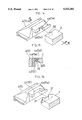
- FIGS. 19 and 20 show a known structure for fixing a shoe to a bicycle pedal through a cleat attached to the bottom of the shoe.
- a pedal shaft 43 rotatably supports a pedal body 44 including a front hook 44a formed on a front end thereof and having an engaging portion having approximately the same width as a front engaging portion of a cleat 45.
- the pedal body 44 also includes a rear hook claw 41 connected to a rear end thereof to be pivotable between an engaging position and a disengaging position.
- the rear hook claw 41 includes a cleat contacting portion 41a and a cleat engaging portion 41b extending axially of the pedal body 44.
- a spring 42 is mounted between the rear hook 41 and pedal body 44 to urge the rear hook claw 41 forwardly toward the engaging position.
- the cleat 45 includes a recessed engaging portion 45a at a rear end thereof for fitting engagement with the rear hook 41.
- Such a known structure is disclosed in the Japanese patent application laid open under No. 60-197478, for example.
- the shoe is releasable from the pedal only by turning the shoe about an imaginary axis perpendicular or approximately perpendicular to the treads of the pedal, using the front end of the cleat 45 as a pivotal point.
- the shoe may not be released from the pedal when, for example, the cyclist falls over to the ground and tilts the shoe sideways relative to the pedal treads.
- the rigid connection between the shoe and bicycle pedal applies a treading force of the cyclist to the pedal effectively and reliably.
- a connection transmits violent vibrations resulting from the roughness of the terrain to the cyclist's foot.
- the known connecting structure between the bicycle pedal and cleat includes engaging members attached to the pedal shaft for connection to the shoe, and the shoe rests on the pedal through the engaging members.
- engaging members are generally formed of a highly rigid material to assure a strong connection to the shoe.
- the torsional force about the imaginary axis noted above may be applied to the shoe connected to the pedal body.
- the cyclist may pedal the bike with only one foot in an unstable posture.
- the cyclist turns the pedal body while applying a torsional force about the above-mentioned imaginary axis to the shoe connected to the pedal body.
- the unstable posture could result in an inadvertent application of a torsional force about the imaginary axis to the shoe connected to the pedal body.
- the shoe could inadvertently disengage from the pedal body under the torsional force applied to the shoe connected to the pedal body.
- the cyclist faces a serious danger as a result of the shoe disengaging from the pedal body while the cyclist is in such an unstable posture.
- To prevent the shoe from inadvertently disengaging from the pedal body it is conceivable to set the torsional force for turning the shoe about the imaginary axis to a high level.
- such a measure would be inappropriate since the shoe would not readily be released from the pedal body in an emergency, such as when the cyclist falls over.
- the shoe must be turned a great extent about the imaginary axis to become disengaged from the pedal body.
- the shoe turned a small amount only results re-engagement between the cleat and engaging members. The cyclist could be seriously injured with the shoe remaining caught with the pedal body.
- a first object of the invention is to provide a connecting structure which releases the cleat with increased reliability when, for example, the cyclist falls over with his shoe inclined relative to the pedal.
- a second object of the present invention is to provide a connecting structure which reduces the strain of the cyclist's foot.
- a third object of the invention is to provide a connecting structure which reliably connects the cleat to the pedal body during a normal run, and allows the cleat to be released from the pedal body in an emergency.
- a connecting structure comprising hooks pivotably supported by a pedal body for engaging and releasing the cleat; an urging device for urging the hooks toward engaging positions; and a first cam mechanism provided between each of the hooks and the cleat for causing the hook to pivot in a releasing direction when the cleat is inclined about a first imaginary axis extending substantially along a direction of pivotal movement of the hooks, the first cam mechanism including a first pressed edge defined on one of the hooks and opposed to the cleat, and a first pressing edge defined on the cleat and opposed to one of the hooks for slidable contact with the first pressed edge, the first pressed edge and the first pressing edge overlapping each other as seen in a direction perpendicular to a tread of the pedal body.
- the first pressed edge and first pressing edge constituting the first cam mechanism overlap each other as seen in the direction perpendicular to a tread of the pedal body. Therefore, the hook pivots when the cleat is inclined about the first imaginary axis extending along the direction of pivotal movement of the hook.
- the first cam mechanism with the inclination of the cleat, causes the hook to pivot in the release direction. So the shoe becomes disengaged from the pedal when the shoe to which the cleat is fixed is twisted to incline the cleat.
- the shoe is released from the pedal even when the shoe is inclined with the foot in an emergency such as falling over of the cyclist. This helps to avoid a danger of spraining or fracturing the foot for promotion of the safety aspect.
- the above connecting structure may further comprise a second cam mechanism provided between each of the hooks and the cleat for causing the hook to pivot in the releasing direction when the cleat is inclined about a second imaginary axis extending substantially perpendicular to a tread of the pedal body, the second cam mechanism including a second pressed edge defined on one of the hooks and opposed to the cleat, and a second pressing edge defined on the cleat and opposed to one of the hooks for slidable contact with the second pressed edge, the second pressed edge of the hook lying in a locus described by the second pressing edge of the cleat when the cleat is swung.
- the hook will pivot with a swinging movement of the cleat since the second cam mechanism is provided which includes a second pressed edge defined on the hook and opposed to the cleat, and a second pressing edge defined on the cleat and opposed to the hook for slidable contact with the second pressed edge, with the second pressed edge of the hook lying in a locus described by the second pressing edge of the cleat when the cleat is swung.
- the second cam mechanism with a swing of the cleat, causes the hook to pivot in the release direction. So the shoe becomes disengaged from the pedal when the shoe to which the cleat is fixed is twisted to incline the cleat.
- the shoe is positively disengaged from the pedal when the cleat is twisted in two or more directions.
- This construction further promotes safety in that the shoe is releasable from the pedal not only with an inclination of the cleat as noted above but with a swinging movement of the cleat.
- the construction may be simple and easy to manufacture if the first pressing edge and second pressing edge comprise a common pressing edge formed on the cleat.
- the first pressing edges comprise opposite side edges of a portion engaged by the hook, and converge toward the hook. This construction assures a smooth pivotal movement of the hook in the release direction whichever direction the cleat may be inclined about the first imaginary axis.
- the pedal body includes a shoe rest for receiving a shoe bottom, the shoe rest at least partly surrounding an engaging device including the hooks and the urging means, and the shoe bottom includes a contact portion at least partly surrounding the cleat for contacting the shoe rest.
- the cyclist's shoe not only is placed on the pedal indirectly through the engaging device but has the contact portion thereof directly placed on the shoe rest formed around the engaging device.
- the shoe is rigidly connected to the pedal through the cleat and engaging device to transmit part of a treading force of the cyclist directly to the shoe rest.
- vibrations transmitted from the pedal to the cyclist's foot are damped between the shoe rest and the shoe bottom by utilizing an elastic material of which the shoe bottom is usually formed.
- the engaging device on the pedal acts both to connect the shoe to the pedal and to receive the treading force of the cyclist.
- the shoe rests on the engaging device itself which has a relatively large area.
- the connecting structure of this invention has the engaging device acting mainly as a connector for the shoe, the function to receive the treading force of the cyclist being fulfilled also by the shoe rest effective to damp the vibrations in combination with the shoe bottom. This reduces the vibrations transmitted through the engaging device to the cyclist's foot without being damped.
- the connecting structure of this invention is extremely useful for such situations in that the cleat is readily releasable from the pedal and that the cyclist is well protected from fatigue.
- a connecting structure in which the pedal body includes rotation restrictors for contacting the cleat engaged by the hooks to restrain the cleat from rotating about the second imaginary axis, cam surfaces being defined on the rotation restrictors and/or the cleat for moving the cleat away from the tread of the pedal body when the cleat engaged by the hooks is rotated about the second imaginary axis.
- the rotation restrictors basically restrain the cleat in the engaged state from rotating about the above imaginary axis.
- the cam surfaces defined on the rotation restrictors or the cleat provide the option, as described hereunder, for the cleat to rotate or not to rotate about the imaginary axis, and hence the option for the cleat to disengage or not to disengage from the pedal body.
- a great treading force is applied to the shoe to tread and turn the pedal body. This treading force is maintained during the normal run unless the shoe is intentionally lifted.
- Such treading force operates through the inclination of the cam surfaces to prevent the cleat from leaving the tread of the pedal body. That is, the cleat in the engaged state cannot rotate without moving away from the tread.
- the function of the cam surfaces is nullified and the rotation of the cleat about the above-mentioned imaginary axis is effectively restrained by the rotation restrictors. For this reason, even if a torsional force around the imaginary axis is applied to the cleat engaged by the pedal body, the cleat will not rotate about the imaginary axis to oscillate the hooks. Since the cleat remains engaged by the hooks, the cleat will never inadvertently become separated from the cleat. On the other hand, in an emergency such as when the cyclist falls over, the cleat may move away from the tread owing to the inclination of the cam surfaces since tile treading force acting on the pedal body is at least temporarily removed.
- the rotation of the cleat about the second imaginary axis is not in any way prevented by the presence of the rotation restrictors.
- the cleat by its rotation, is disengageable from the hooks to separate from the pedal body.
- the cleat becomes disengaged from and moves away from the hooks, so that inadvertent reengagement between the cleat and hooks is positively avoided.
- the cleat is reliably separable from the pedal body for the same reason also when the cleat is rotated about the imaginary axis without a treading force applied intentionally. This promotes safety of the cyclist during a run while allowing the cyclist to turn the pedal body with full force despite an unstable posture such as in cornering.
- the hooks are provided at the front end of the pedal body as well as the rear end thereof, a great pressure applied forwardly of the pedal could result in disengagement between the front hook and the cleat, whereby the cleat inadvertently becomes disengaged from the pedal.
- a connecting structure comprises a pedal body further including forward movement stoppers for contacting the cleat engaged by the hooks to prevent movement of the cleat forwardly of the pedal and allow rotation of the cleat about the second imaginary axis.
- the forward movement stoppers are effective to prevent the front hook from pivoting forwardly of the pedal body when a great forward pressure acts on the front hook.
- the cleat in the engaged state will not move away from the tread of the pedal, and therefore will not move over the forward movement stoppers.
- a great pressure acts on the cleat such as when the cyclist pedals the bicycle with full force or suddenly applies brakes
- the front hook is free from the pressure and the cleat remains engaged without allowing the shoe to inadvertently separate from the pedal.
- the connecting structure including the forward movement stoppers realizes optimal hooks for allowing the cleat to be engaged by the pedal through a treading operation relative to the pedal. This is possible because no means is necessary for retarding the forward pivotal movement of the front hook.
- the forward movement stoppers allow the cleat to rotate about the second imaginary axis. Thus, the cleat may be rotated to readily disengage from the pedal.
- the cleat separation may be further facilitated if the rear end of the cleat, which may be rotated or swung most easily from the point of view of human engineering, is rotatable about the second imaginary axis.
- FIGS. 1 through 8 show a first embodiment of the present invention, in which:
- FIG. 1 is a perspective view of a connecting structure
- FIG. 2 is a perspective view of a principal portion of the connecting structure seen from a different angle
- FIG. 3 is a view in vertical section of the connecting structure, taken along the line 3--3 of FIG. 1,
- FIGS. 4 through 6 are plan views for illustrating the way in which the connecting structure operates
- FIG. 7 is a rear view, partly broken away, of the connecting structure seen in a direction perpendicular to a pedal shaft, and
- FIG. 8 is a plan view showing a relationship between the connecting structure and a cleat.
- FIGS. 9 through 13 show a second embodiment of the present invention, in which:
- FIG. 9 is a perspective view showing a relationship between a cleat and a pedal
- FIGS. 10 and 11 are sectional views showing a relationship between the rear end of the cleat and a rotation restricting portion
- FIGS. 12 and 13 are schematic plan views showing the relationship between the rear end of the cleat and the rotation restricting portion.
- FIG. 14 is a perspective view of a modification made to the first embodiment.
- FIG. 15 is a sectional view of a principal portion of the modification shown in FIG. 14, taken along the line 15--15 of FIG. 14.
- FIG. 16 is a perspective view of another modification made to the first embodiment.
- FIGS. 17 and 18 are views showing modifications made to the second embodiment.
- FIG. 19 is a view in vertical section of a conventional connecting structure between a bicycle pedal and a cleat, taken along the line 19--19 of FIG. 20.
- FIG. 20 is a plan view of the conventional connecting structure shown in FIG. 19.
- numeral 1 denotes a pedal shaft attached to a free end of a crank arm of a bicycle crank
- numeral 2 denotes a pedal body rotatably supported by the pedal shaft 1.
- the pedal body 2 includes connecting means for rotatably connecting the pedal to the pedal shaft 1, and thus to the bicycle crank.
- the connecting means is arranged such that the pedal rotates about a first axis with respect to the crank.
- Two types of hooks 4 and 5 are pivotably supported by the pedal body 2, more particularly by each of two pivotal axes 7 included in the pedal body 2, to engage and release a cleat 3 attached to a bottom of a shoe for fixing the shoe to the bicycle pedal.
- the hook 4 engages a front engaging portion 3a of the cleat 3, while the hook 5 engages a rear engaging portion 3a of the cleat 3.
- the two hooks 4 and 5 forming a vertical pair are pivotable on a pivotal point P provided by each of the forward and rearward pivotal shafts or axes 7, and the two pairs of hooks 4 and 5 are in fore and aft rotation symmetry.
- Each of the hooks 4 and 5 is formed of aluminum, with engaging elements 4a or 5a of steel secured thereto by a bolt 16 or 17 since certain strength is required at a position thereof which directly contacts the cleat 3.
- the cleat is bolted to the shoe bottom S through two slots 3' to be adjustable sideways.
- the engaging portions 3a of the cleat have inclined undersurfaces 3u, so that a pedal treading action of the cyclist causes pivotal movement of the hooks 4 and 5.
- the hooks 4 and 5 have helical springs 6 for urging the hooks 4 and 5 to the engaging positions.
- Each of the helical springs 6 is mounted on each pivotal axis supporting the vertical pair of hooks 4 and 5, such that the helical spring 6 is out of contact with intermediate recesses 4c and 5c defined in the hooks 4 and 5.
- Each helical spring 6 has an end thereof contacting a deformed nut 10 meshed with a threaded portion 9a of an adjusting bolt 9 positioned and rotatably supported through a washer-like element 8 in a center position adjacent the pivotal connection of the hook 4 for engaging the front end of the cleat 3.
- the position of the deformed nut 10 is adjustable by rotating the adjusting bolt 9.
- each helical spring 6 has one end extending to the hook 4 for engaging the front end of the cleat 3, and the other end extending to the hook 5 for engaging the rear end of the cleat 3, to urge the hooks 4 and 5 to the engaging positions, with its urging force adjustable by the adjusting bolt 9.
- the hook 4 for engaging the front end of the cleat 3 includes a window 4b in a transversely intermediate position thereof for allowing a visual confirmation of the position of the deformed nut 10 meshed with the adjusting bolt 9.
- the deformed nut 10 is bent at a position thereof adjacent an outer profile of the pedal to extend along the adjusting bolt 9, with an end face 10a thereof serving the purpose of visual confirmation through the window 4b.
- the position of the deformed nut 10 is confirmed by seeing this end face 10a through the window, thereby to check the urging condition of the helical spring 6.
- Numeral 19 denotes a cleat rest with contact plates for contacting the cleat 3, each of which is attached to the pedal body 2 with a projection of the pedal body 2 fitted in a perforation formed centrally of the contact plate 19.
- a first cam mechanism A is provided between each of the hooks 4 and 5 and the cleat 8, more particularly between each of the engaging portions of elements 4a and 5a of the hooks 4 and 5 and each of the engaging portions 3a of the cleat.
- the cam mechanisms A cause the hooks 4 and 5 to pivot toward the release positions when the cleat 3 is inclined, as shown in FIG. 6, about a first imaginary axis X 1 extending along the direction of pivotal movement of the hooks 4 and 5.
- Each of the first cam mechanisms A includes a first pressed edge or hooking edge 4e or 5e (which is pressed when the shoe is released) formed linearly on a position of the hook 4 or 5 opposed to the cleat 3 , and a first pressing cleat edge 3e (which applies a pressing force when the shoe is released) formed in a bent shape (which may be curved though not shown) under a position of the cleat 3 opposed to the hook 4 or 5 for slidable contact with the first pressed edge 4e or 5e.
- FIG. 4 which is seen in the direction perpendicular to a tread face of the pedal body 2, the first pressed edge 4e or 5e and the first pressing edge 3e, when engaged, overlap each other.
- a second cam mechanism B is provided between each of the hooks 4 and 5 and the cleat 3, more particularly between each of the engaging elements 4a and 5a of the hooks 4 and 5 and each of the engaging portions 3a of the cleat .
- the cam mechanisms B cause the hooks 4 and 5 to pivot toward the release positions when the cleat 3 is inclined about a second imaginary axis X 2 extending substantially perpendicular to the tread of the pedal body 2.
- Each of the second cam mechanisms B includes a second pressed edge or hook contact portion 4f or 5f formed in a bent shape on a position of the hook 4 or 5 opposed to the cleat 3, and a second pressing edge or cleat contact portion 3f projecting from an upper position of the cleat 3 opposed to the hook 4 or 5 for slidable contact with the second pressed edge 4f or 5f.
- the pressed edge 4e or 5e of the hook 4 or 5 lies in a locus described by the second pressing edge 3f when the cleat 3 is turned (from the position shown in FIG. 4 to the position shown in FIG. 5).
- the connecting structure between the bicycle pedal and cleat includes the cam mechanisms A each having the first pressed edge 4e or 5e of the hook 4 or 5 and the first pressing edge 3e of the cleat 3 overlapping each other when seen in the direction perpendicular to the tread of the pedal body 2.
- the cam mechanisms A When the cleat 3 is inclined about the first imaginary axis extending along the direction of pivotal movement of the hooks 4 and 5, the cam mechanisms A cause the hooks 4 and 5 to pivot toward the release positions, thereby releasing the shoe with the cleat 3 fixed thereto from the pedal.
- This connecting structure also includes the second cam mechanisms B for causing the hooks 4 and 5 to pivot toward the release positions when the cleat 3 is inclined about the second imaginary axis extending substantially perpendicular to the tread of the pedal body 2.
- the cam mechanisms B cause the hooks 4 and 5 to pivot toward the release positions, thereby releasing the shoe with the cleat 3 fixed thereto from the pedal.
- the pedal body 2 includes a shoe rest (with inner and outer pedal surfaces) 2X formed of an elastic material for receiving the shoe bottom S.
- This shoe rest 2X surrounds a cleat connecting device including the hooks 4 and 5, helical springs 6 and pivotal axes 7.
- the shoe includes a contact portion Sb formed around the cleat 3 for contacting the shoe rest 2X of the bicycle pedal. When the shoe bottom S is connected to the connecting device 18, the shoe rest 2X receives the contact portion Sb of the shoe bottom S.
- This construction transmits part of the treading force of the cyclist from the contact portion Sb of the shoe bottom S directly to the pedal body 2, and at the same time the elasticity of the shoe bottom S absorbs vibrations due to roughness of the terrain transmitted as a reaction to the treading force from the pedal body 2 to the cyclist's foot, thereby reducing the strain of the cyclist's foot.
- the shoe bottom S includes a recess Sa with bolt holes formed in the bottom of this recess Sa, and the cleat 3 is removably bolted to the shoe bottom S.
- the cleat 3 is removed from the shoe bottom S and a solid filling material is fitted into the recess Sa and fixed in position by an adhesive, for example. Then the shoe becomes an ordinary walking shoe.
- the cleat 3 acts primarily to connect the shoe to the pedal, and the treading force is transmitted from the contact portion Sb of the shoe bottom S and the shoe rest 2X. This construction allows the cleat 3 to be compact, and therefore a cutout need not be defined in the shoe as in the prior art. Since the cleat 3 is surrounded entirely by the shoe bottom S, the cyclist can stably place his foot on the ground.
- FIGS. 9 through 13 A second embodiment of the present invention will be described next with reference to FIGS. 9 through 13. This embodiment is similar in construction to the preceding embodiment except the cleat and the cleat contact plates.
- a cleat 30 includes a front engaging portion 30a and a rear engaging portion 30b for engagement with the hooks (first and second cleat retaining means) 4 and 5, respectively.
- the front engaging portion 30a has a semicircular top 30c of a half cylinder projecting from a top surface thereof.
- the rear engaging portion 30b defines a second pressing edge 30f projecting upwardly.
- the front engaging portion 30a defines oblique contact portions 30d at opposite sides thereof for contacting forward movement stoppers 20a to be described hereunder.
- a cleat contact plate (base) 20 formed of steel has right and left front corners bent upward.
- Each of these upwardly bent portions defines an oblique forward movement stopper 20a for contacting the contact portion 30d of the cleat 30, and a rotation restrictor 20b for contacting a side of the front engaging portion 30a.
- the cleat contact place 20 has right and left rear portions bent upward.
- Each of these upwardly bent portions defines a rear rotation restrictor or guide element 20c for contacting a side of the cleat 30.
- the two rear rotation restrictors 20c are inclined in a way to diverge upwardly away from a tread 2' of the pedal body 2, thereby defining cam or guide surfaces 20d.
- the front rotation restrictors 20b contact the opposite sides at the front end of the cleat 30 to prevent lateral movement of the front end of the cleat 30, and the forward movement stoppers 20a contact the oblique contact portions 30d of the cleat 30 to prevent forward movement of the cleat 30.
- the rear end of the cleat 30, by the action of the cam surfaces 20d remains away from the tread 2' of the pedal body 2 in the absence of a treading force.
- the cam surfaces 20d act as the rear rotation restrictors 20c to prevent lateral movement of the rear end of the cleat 30. Consequently, the rotation of the cleat 30 about the second imaginary axis X is prevented mainly when a treading force is applied.
- the cleat For disconnecting the shoe from the pedal body 2, the cleat may just be turned about the second imaginary axis X as shown in FIGS. 11 and 12, with no treading force applied to the rear end of the cleat 30.
- the front end of the cleat 30 is restrained from lateral movement by the front rotation restrictors 20b, so that the second imaginary axis X extends through a position adjacent the front rotation restrictors 20b.
- the rear hook 5 pivots rearwardly through a relative sliding movement between the second pressing edge 30f at the rear end of the cleat 30 and a cam surface 5b of the rear hook 5.
- the cleat 30 is thereby disengaged from the hooks 4 and 5 to complete disconnection between the shoe and the pedal body 2. In this way, the cyclist can positively select connection or disconnection of the cleat 30 or shoe to/from the pedal body 2 according to circumstances.
- the treading force is at least temporarily removed from the pedal body 2.
- the cleat 30 may become disengaged from the pedal body 2 through a behavior similar to the intentional operation described above, thereby to secure safety of the cyclist.
- the rear end of the cleat moves away from the tread 2' of the pedal body 2 under the guiding action of the cam surfaces 20d.
- the cleat 30 becomes disengaged from and moves away from the rear hook 5, so that inadvertent re-engagement between the cleat 30 and the rear hook 5 is positively avoided.
- the first and second pressing edges of the cleat 3 may be in the form of one pressing portion 3g of the cleat 3.
- the pressing portion 3g acts as a first cam mechanism A in combination with a first pressed edge 4e' or 5e' of the hook 4 or 5, and as a second cam mechanism B in combination with a second pressed edge 4f' or 5f' of the hook 4 or 5. Further, it is possible to provide the first cam mechanisms A only.
- the second pressing edge 3f and the second pressed edge 4f or 5f may be reversed as to the projection/recess relationship. Further, as shown in FIG. 16, the second pressing edge 3f may include two projections.
- the pair of hooks 4 and 5 may be provided only on one face of the pedal body 2 instead of both faces thereof.
- the connecting device 18 may be varied as desired.
- the cleat 3 may be engaged at the front end by a stationary member, the rear end of the cleat 3 being clamped at right and left by hooks.
- the shape and size of the shoe rest 2X are variable with the connecting device 18. Where the connecting device 18 is elongated axially of the pedal shaft 1, the shoe rest 2X may be split fore and aft across the connecting device 18. In other words, the shoe rest 2X will serve the purpose as long as it is positioned around the connecting device 18. The shoe rest 2X may partly or entirely surround the connecting device 18.
- the rear rotation restrictors 20c and cam surfaces 20d are arranged to contact the cleat 80.
- these components may be adapted to contact the shoe bottom S.
- the pedal body 2 may include projections formed on each tread thereof and defining the rear rotation restrictors 20c acting as cam surfaces 20d, the rear rotation restrictors 20c being arranged to contact surfaces F2 in holes defined in the shoe bottom S.
- the shoe bottom S is restrained from rotation about the second imaginary axis X by the contact between the rear rotation restrictors 20c and the surfaces F2.
- the shoe bottom S and cleat 30 are movable away from the tread 2' of the pedal body 2 with rotation about the second imaginary axis X of the shoe bottom S.
- cam surfaces 20d are provided on the rear rotation restrictors 20c in the second embodiment and modification 6 above, the cam surfaces 20d may be formed on the cleat 30 or shoe bottom S only or may by formed on the cleat 30 or shoe bottom S as well as the rear rotation restrictors 20c. As shown in FIG. 18, for example, the rear rotation restrictors 20c may extend substantially perpendicular to the tread 2' of the pedal body 2, with the cleat 30 defining cam surfaces 20d at opposite sides at rear positions thereof which are inclined to converge downwardly. This construction corresponds to the second embodiment in function and effect.
- cam surfaces 20d are provided on the rear rotation restrictors 20c in the second embodiment, the cam surfaces 20d may be formed on the front rotation restrictors 20b only or may be formed on both the front rotation restrictors 20b and the rear rotation restrictors 20c.
- the second imaginary axis X is located rearwardly of the cleat 30, while in the latter the position of axis X variable with the way a couple of forces is applied to the cleat 30.
- the relationship between the semicircular top 30c and the second pressing edge 3f and second pressed edge 5f may be reversed fore and aft from their relationship in the second embodiment.
- both of the hooks 4 and 5 are pivotable, only one of them may be constructed pivotable and the other formed integral with the pedal body.
- the front and rear rotation restrictors 20b and 20c are distributed right and left of the pedal body 2.
- the rotation restrictors may be provided only at one front position and one rear position of the pedal body 2.
- the rotation restrictors 20c and 20d may be provided centrally of the pedal body 2 instead of the two positions at the front and rear thereof.
- only one cam surface may be provided on the pedal body 2 instead of two.
- the forward movement stoppers 20a are provided in the forward portions of the pedal body 2, these may be provided centrally or rearwardly of the pedal body 2.
- the two forward movement stoppers 20a may be replaced by one forward movement stopper for contacting the entire front end of the cleat 30. This construction corresponds to the second embodiment in function and effect.
Landscapes
- Engineering & Computer Science (AREA)
- Chemical & Material Sciences (AREA)
- Combustion & Propulsion (AREA)
- Transportation (AREA)
- Mechanical Engineering (AREA)
- Footwear And Its Accessory, Manufacturing Method And Apparatuses (AREA)
Priority Applications (5)
| Application Number | Priority Date | Filing Date | Title |
|---|---|---|---|
| US07/971,269 US5522282A (en) | 1989-11-14 | 1992-11-04 | Connecting structure between bicycle pedal and cleat, bicycle pedal and cleat |
| US08/180,307 US5505111A (en) | 1989-11-14 | 1994-01-12 | Connecting structure between bicycle pedal and cleat, bicycle pedal and cleat |
| US08/597,213 US5699699A (en) | 1989-11-14 | 1996-02-06 | Connecting structure between bicycle pedal and cleat, bicycle pedal and cleat |
| US08/851,935 US5855147A (en) | 1989-11-14 | 1997-05-06 | Connecting structure between bicycle pedal and cleat, bicycle pedal and cleat |
| US09/183,867 US6089122A (en) | 1989-11-14 | 1998-10-30 | Connecting structure between bicycle pedal and cleat, bicycle pedal and cleat |
Applications Claiming Priority (10)
| Application Number | Priority Date | Filing Date | Title |
|---|---|---|---|
| JP29641589A JPH03157284A (ja) | 1989-11-14 | 1989-11-14 | 自転車用ペタルとクリートとの連結部構造 |
| JP1-296415 | 1989-11-14 | ||
| JP1-297860 | 1989-11-16 | ||
| JP29786189A JPH03159893A (ja) | 1989-11-16 | 1989-11-16 | 自転車用ペダルとクリートとの係止部構造 |
| JP29786089A JPH0411592A (ja) | 1989-11-16 | 1989-11-16 | 自転車用ペダルとクリートとの係止部構造及び自転車用ペダルと靴との係止部構造 |
| JP1-297861 | 1989-11-16 | ||
| JP1-135980U | 1989-11-22 | ||
| JP1989135980U JP2503448Y2 (ja) | 1989-11-22 | 1989-11-22 | 自転車用ペダル |
| US61150490A | 1990-11-13 | 1990-11-13 | |
| US07/971,269 US5522282A (en) | 1989-11-14 | 1992-11-04 | Connecting structure between bicycle pedal and cleat, bicycle pedal and cleat |
Related Parent Applications (1)
| Application Number | Title | Priority Date | Filing Date |
|---|---|---|---|
| US61150490A Continuation | 1989-11-14 | 1990-11-13 |
Related Child Applications (2)
| Application Number | Title | Priority Date | Filing Date |
|---|---|---|---|
| US08/180,307 Continuation US5505111A (en) | 1989-11-14 | 1994-01-12 | Connecting structure between bicycle pedal and cleat, bicycle pedal and cleat |
| US08/597,213 Division US5699699A (en) | 1989-11-14 | 1996-02-06 | Connecting structure between bicycle pedal and cleat, bicycle pedal and cleat |
Publications (1)
| Publication Number | Publication Date |
|---|---|
| US5522282A true US5522282A (en) | 1996-06-04 |
Family
ID=27471966
Family Applications (5)
| Application Number | Title | Priority Date | Filing Date |
|---|---|---|---|
| US07/971,269 Expired - Lifetime US5522282A (en) | 1989-11-14 | 1992-11-04 | Connecting structure between bicycle pedal and cleat, bicycle pedal and cleat |
| US08/180,307 Expired - Lifetime US5505111A (en) | 1989-11-14 | 1994-01-12 | Connecting structure between bicycle pedal and cleat, bicycle pedal and cleat |
| US08/597,213 Expired - Lifetime US5699699A (en) | 1989-11-14 | 1996-02-06 | Connecting structure between bicycle pedal and cleat, bicycle pedal and cleat |
| US08/851,935 Expired - Fee Related US5855147A (en) | 1989-11-14 | 1997-05-06 | Connecting structure between bicycle pedal and cleat, bicycle pedal and cleat |
| US09/183,867 Expired - Fee Related US6089122A (en) | 1989-11-14 | 1998-10-30 | Connecting structure between bicycle pedal and cleat, bicycle pedal and cleat |
Family Applications After (4)
| Application Number | Title | Priority Date | Filing Date |
|---|---|---|---|
| US08/180,307 Expired - Lifetime US5505111A (en) | 1989-11-14 | 1994-01-12 | Connecting structure between bicycle pedal and cleat, bicycle pedal and cleat |
| US08/597,213 Expired - Lifetime US5699699A (en) | 1989-11-14 | 1996-02-06 | Connecting structure between bicycle pedal and cleat, bicycle pedal and cleat |
| US08/851,935 Expired - Fee Related US5855147A (en) | 1989-11-14 | 1997-05-06 | Connecting structure between bicycle pedal and cleat, bicycle pedal and cleat |
| US09/183,867 Expired - Fee Related US6089122A (en) | 1989-11-14 | 1998-10-30 | Connecting structure between bicycle pedal and cleat, bicycle pedal and cleat |
Country Status (3)
| Country | Link |
|---|---|
| US (5) | US5522282A (fr) |
| EP (4) | EP0576042B1 (fr) |
| DE (4) | DE69018196T2 (fr) |
Cited By (23)
| Publication number | Priority date | Publication date | Assignee | Title |
|---|---|---|---|---|
| US5634383A (en) * | 1996-03-29 | 1997-06-03 | Lin; Wen-Hwa | Bicycle shoe plate holding-down device |
| US5692415A (en) * | 1996-03-29 | 1997-12-02 | Lin; Wen-Hwa | Bicycle pedal having two surfaces for coupling to a bicycle shoe |
| US5697262A (en) * | 1996-09-16 | 1997-12-16 | Chen; Chung-I | Quick-release pedal |
| US5727429A (en) * | 1996-08-26 | 1998-03-17 | Shimano, Inc. | Low profile bicycle pedal and cleat assembly |
| US5755144A (en) * | 1996-08-26 | 1998-05-26 | Shimano, Inc. | Low profile bicycle pedal with top and bottom side clamping arrangements |
| US5778739A (en) * | 1996-08-26 | 1998-07-14 | Shimano, Inc. | Bicycle pedal with gap adjusting mechanism |
| US6089122A (en) * | 1989-11-14 | 2000-07-18 | Shimano, Inc. | Connecting structure between bicycle pedal and cleat, bicycle pedal and cleat |
| US6374699B1 (en) * | 1999-01-22 | 2002-04-23 | Look Cycle Internationale | Automatic cycle pedal |
| US6425304B1 (en) | 2000-12-01 | 2002-07-30 | Speedplay, Inc. | Clipless pedal and method for assembling it |
| US20020170382A1 (en) * | 2001-05-17 | 2002-11-21 | Yang Ta Hsin | Safety cycle pedal |
| US6557884B1 (en) | 1997-04-18 | 2003-05-06 | The Burton Corporation | Active engagement system for engaging a snowboard boot to a binding |
| US20040021278A1 (en) * | 1999-01-11 | 2004-02-05 | Lyden Robert M. | Wheeled skate with step-in binding and brakes |
| US6722688B2 (en) | 2001-11-21 | 2004-04-20 | The Burton Corporation | Snowboard binding system |
| US6837128B2 (en) * | 2000-06-23 | 2005-01-04 | Campagnolo S.R.L. | Bicycle safety pedal |
| US20080060647A1 (en) * | 2006-09-12 | 2008-03-13 | Invacare Corporation | System and method for delivering a breathing gas |
| US20090095122A1 (en) * | 2007-10-10 | 2009-04-16 | David Weagle | Removable pedal platform |
| CN101450700B (zh) * | 2007-12-04 | 2011-12-21 | 株式会社岛野 | 自行车踏板 |
| US10221887B2 (en) | 2012-12-06 | 2019-03-05 | The Hive Global, Inc | Self locking bearing preload adjuster |
| US10562588B2 (en) | 2015-09-01 | 2020-02-18 | The Hive Global, Inc | Bicycle cassette with locking connection |
| US10669211B2 (en) | 2015-12-30 | 2020-06-02 | 3M Innovative Properties Compnay | Acoustically active articles |
| US11142280B2 (en) | 2016-03-24 | 2021-10-12 | The Hive Global, Inc. | Bicycle crank with spindle attachment structure |
| US11351815B2 (en) | 2017-08-21 | 2022-06-07 | The Hive Global, Inc. | Bicycle cassette with clamping connection |
| US11932351B2 (en) | 2020-07-17 | 2024-03-19 | The Hive Global, Inc. | Conical bicycle cassette sprocket structure |
Families Citing this family (50)
| Publication number | Priority date | Publication date | Assignee | Title |
|---|---|---|---|---|
| EP0516013B1 (fr) * | 1991-05-30 | 1997-01-08 | Shimano Inc. | Dispositif pour une pédale de bicyclette avec surface de la pédale variable |
| IT1254087B (it) * | 1991-09-10 | 1995-09-07 | Danieli Calzaturificio Spa | Dispositivo per il fissaggio di una calzatura ad un pedale di bicicletta |
| JPH05131968A (ja) * | 1991-11-13 | 1993-05-28 | Shimano Inc | 自転車用のペダルと靴との連結構造 |
| DE4206106C2 (de) * | 1992-02-27 | 2000-10-12 | Look Sa | Vorrichtung zur Befestigung eines Schuhes an einem Fahrradpedal |
| AU631083B1 (en) * | 1992-03-24 | 1992-11-12 | Chung-I Chen | Quick-release clipless pedal with two cleat engaging sides |
| GB2266497B (en) * | 1992-04-28 | 1995-04-26 | Chen Chung I | Quick-release clipless pedal with two cleat engaging sides |
| FR2695902B1 (fr) * | 1992-09-22 | 1996-03-08 | Look Sa | Dispositif de fixation pour fixer de maniere detachable une chaussure a une pedale de cycle. |
| IT1257143B (it) * | 1992-11-04 | 1996-01-05 | Antonio Romano | Pedale di sicurezza per biciclette e simili. |
| US5279184A (en) * | 1992-12-29 | 1994-01-18 | Mikashima Industrial Co., Ltd. | Shoe fixing device of bicycle pedal |
| US5259270A (en) * | 1992-12-30 | 1993-11-09 | Lin Wen Hwa | Bicycle pedal |
| TW262444B (fr) * | 1993-04-08 | 1995-11-11 | Marui Kk | |
| JP2986377B2 (ja) * | 1995-07-12 | 1999-12-06 | 株式会社シマノ | 自転車用ペダル |
| JP3290566B2 (ja) * | 1995-07-12 | 2002-06-10 | 株式会社シマノ | 自転車用ペダル |
| TW393413B (en) * | 1996-01-19 | 2000-06-11 | Shimano Kk | Clipless bicycle pedal with large shoe-contacting area |
| US5992266A (en) | 1996-09-03 | 1999-11-30 | Jonathan R. Heim | Clipless bicycle pedal |
| US5916332A (en) * | 1997-08-25 | 1999-06-29 | Chen; Chung-I | Pedal assembly of a bicycle |
| FR2768391B1 (fr) * | 1997-09-18 | 1999-10-15 | Suzanne Huguette Beyl | Pedale de bicyclette a fixation de securite, et dispositif de fixation d'une chaussure sur la pedale |
| US7104158B2 (en) * | 1998-09-03 | 2006-09-12 | Harrington Jeffrey M | Bicycle pedal and shoe connection system and method |
| US6014914A (en) * | 1998-11-05 | 2000-01-18 | Shimano Inc. | Bicycle pedal |
| US6012356A (en) * | 1998-11-05 | 2000-01-11 | Shimano Inc. | Bicycle pedal with gap adjustment mechanism |
| US6119551A (en) * | 1998-11-05 | 2000-09-19 | Shimano Inc. | Bicycle pedal and bicycle cleat |
| US6105462A (en) * | 1999-03-01 | 2000-08-22 | Shimano Inc. | Bicycle pedal |
| US6196084B1 (en) * | 1999-03-01 | 2001-03-06 | Shimano Inc. | Bicycle cleat |
| US6572250B1 (en) * | 1999-03-15 | 2003-06-03 | Britax Wingard Limited | Exterior mirror having an attachment member including an approach light |
| USD425828S (en) * | 1999-03-18 | 2000-05-30 | Shimano, Inc. | Bicycle cleat |
| US6341540B2 (en) | 1999-04-06 | 2002-01-29 | John Douglas Steinberg | Clipless pedal |
| US6234046B1 (en) | 1999-04-23 | 2001-05-22 | William Blake Coombe | Retention mechanism, pedal body and shoe cleat for a clipless bicycle pedal |
| US6324941B1 (en) * | 2000-02-29 | 2001-12-04 | Hsiu-Wei Ho | Snap-in bicycle pedal |
| FR2807384B1 (fr) * | 2000-04-07 | 2002-06-21 | Look Cycle Int | Dispositif de fixation automatique et pedale de cycliste pourvue d'un tel dispositif |
| DE10105034B4 (de) * | 2001-02-05 | 2005-11-03 | Chung-I Chen | Fahrrad-Pedalaufbau, versehen mit stirnseitigen Anschlagselementen zur Verhinderung der Lateralbewegung einer Pedalplatte |
| US6708584B2 (en) * | 2001-09-18 | 2004-03-23 | Shimano, Inc. | Bicycle pedal assembly |
| US6845688B2 (en) | 2001-09-18 | 2005-01-25 | Shimano Inc. | Bicycle pedal assembly |
| AT411899B (de) * | 2002-04-05 | 2004-07-26 | Malle Oeg Tech Buero Fuer Masc | Pedal für ein fahrrad |
| US6729204B1 (en) * | 2003-04-15 | 2004-05-04 | Chung-I Chen | Bicycle pedal assembly with a cleat adapted to be connected fixedly to a shoe |
| EP1527988B1 (fr) * | 2003-10-29 | 2008-05-14 | Chung-I Chen | Ensemble de pédale pour bicyclette et cale d'accrochage |
| US20050103154A1 (en) * | 2003-11-14 | 2005-05-19 | Shimano Inc. | Bicycle pedal |
| US7013755B2 (en) * | 2003-11-14 | 2006-03-21 | Shimano Inc. | Bicycle pedal assembly |
| US20050210712A1 (en) * | 2004-03-26 | 2005-09-29 | Jau Guo J | Shoe attachment assembly for various cycles |
| FR2882658B1 (fr) * | 2005-03-07 | 2007-05-04 | Salomon Sa | Dispositif de fixation a double commande |
| US7204789B1 (en) * | 2005-10-18 | 2007-04-17 | Lo Pin Wang | Pedal device for cycling apparatus |
| US9826794B2 (en) | 2008-12-12 | 2017-11-28 | Speedplay, Inc. | Shoe sole mounting standard for bicycle cleat |
| US8312791B2 (en) * | 2009-10-14 | 2012-11-20 | Shimano Inc. | Bicycle pedal |
| TW201143657A (en) * | 2010-06-11 | 2011-12-16 | Haka Co Ltd | Cycling shoe |
| US8794106B2 (en) * | 2011-08-31 | 2014-08-05 | Evolution Racing Products, Llc | Mechanical restraint for securing motorcycle rider footwear to footpeg |
| USD755684S1 (en) | 2014-08-20 | 2016-05-10 | Fly Pedals LLC | Bicycle clipless pedal platform adapter |
| US9596906B2 (en) * | 2015-04-23 | 2017-03-21 | Action Sports Equipment, Inc. | Article of footwear with concave portion |
| USD798776S1 (en) * | 2015-08-19 | 2017-10-03 | Fly Pedals LLC | Bicycle pedal platform adapter |
| US10689065B2 (en) * | 2018-09-28 | 2020-06-23 | Shimano Inc. | Bicycle pedal and bicycle cleat |
| DE202022101854U1 (de) | 2022-04-06 | 2022-05-17 | Götz Heine | Fahrradschuh mit einer Fahrradschuhsohle |
| WO2023244486A1 (fr) * | 2022-06-12 | 2023-12-21 | Keys Jeramie J | Découplage d'une chaussure d'une pédale de bicyclette |
Citations (13)
| Publication number | Priority date | Publication date | Assignee | Title |
|---|---|---|---|---|
| US4089236A (en) * | 1975-05-13 | 1978-05-16 | Claude Genzling | Safety connection between bicycle pedal and shoe |
| FR2442175A1 (fr) * | 1978-11-24 | 1980-06-20 | Badersbach Jean | Dispositif de fixation d'une chaussure sur une pedale de bicyclette |
| US4302987A (en) * | 1978-11-11 | 1981-12-01 | Shimano Industrial Company, Limited | Pedal for bicycle |
| EP0146454A2 (fr) * | 1983-12-16 | 1985-06-26 | Sté. Look Société Anonyme | Dispositif de fixation d'une chaussure sur une pédale de bicyclette |
| EP0146218A2 (fr) * | 1983-09-28 | 1985-06-26 | John Winkie | Agencement de pédale |
| FR2609270A1 (fr) * | 1987-01-07 | 1988-07-08 | Poutrait Morin | Dispositif de fixation d'une chaussure sur une pedale de bicyclette |
| FR2620409A1 (fr) * | 1987-09-10 | 1989-03-17 | Shimano Industrial Co | Pedale de bicyclette avec cale-pied a durete reglable pour y fixer une semelle |
| DE3937358A1 (de) * | 1988-11-10 | 1990-05-17 | Shimano Industrial Co | Plattenartiges teil eines schuhs zum verbinden mit einem fahrradpedal |
| US4932287A (en) * | 1988-11-07 | 1990-06-12 | Dennis Ramos | Combined shoe and pedal for sports bicycle |
| EP0372165A2 (fr) * | 1988-08-12 | 1990-06-13 | Shimano Inc. | Pédal de cycle |
| DE3924601A1 (de) * | 1989-07-25 | 1991-01-31 | Look Sa | Vorrichtung zum verbinden eines schuhs mit einem fahrradpedal |
| GB2239780A (en) * | 1990-01-16 | 1991-07-17 | Shimano Industrial Co | Cycling shoe |
| US5046382A (en) * | 1990-02-20 | 1991-09-10 | Steinberg John D | Clipless bicycle pedal system |
Family Cites Families (31)
| Publication number | Priority date | Publication date | Assignee | Title |
|---|---|---|---|---|
| US581181A (en) * | 1897-04-20 | Pedal for velocipedes | ||
| EP0058438A3 (fr) * | 1981-02-13 | 1984-04-04 | Jean Badersbach | Pédale de bicyclette permettant l'accrochage d'une chaussure en position préréglée et chaussure de cycliste adaptée à ladite pédale |
| FR2521837A1 (fr) * | 1982-02-22 | 1983-08-26 | Adidas Chaussures | Dispositif cale-pedale pour chaussures de cyclisme |
| IT8204986V0 (it) * | 1982-07-09 | 1982-07-09 | Bacchilega Mario & C Cam | Pedale per biciclette sportive |
| FR2556304A1 (fr) * | 1983-12-09 | 1985-06-14 | Lyotard P Ets | Pedale perfectionnee de bicyclettes et vehicules similaires |
| DE3561870D1 (en) * | 1984-05-18 | 1988-04-21 | Beyl Jean Joseph Alfred | Fastening device for a shoe to a pedal, shoe and pedal provided with this device |
| IT1179709B (it) * | 1984-06-01 | 1987-09-16 | Antonio Rapisarda | Dispositivo per intercollegare un pedale di bicicletta ed una scarpa da ciclista |
| IT1196479B (it) * | 1986-07-08 | 1988-11-16 | Campagnolo Spa | Dispositivo di aggancio della scarpa di una ciclista al pedale di una bicicletta da competizione o sportiva |
| US4815333A (en) * | 1987-02-19 | 1989-03-28 | Sampson Sports, Inc. | Integrated bicycle pedal with self centering and lateral release capabilities |
| FR2612869B1 (fr) * | 1987-03-24 | 1992-09-04 | Bon Raymond | Pedale pour cycles comportant un moyen de fixation rapide d'une chaussure |
| GB8707337D0 (en) * | 1987-03-27 | 1987-04-29 | Pettite A J | Bicycle pedal |
| US4819504A (en) * | 1987-05-27 | 1989-04-11 | Sampson Sports, Inc. | Self contained braking system for bicycle pedals |
| IT210729Z2 (it) * | 1987-05-28 | 1989-01-11 | Rapisarda Antonio | Dispositivo per intercollegare un pedale di bicicletta ed una scarpa da ciclista |
| FR2616738B1 (fr) * | 1987-06-22 | 1992-06-12 | Bidal Rene | Dispositif de fixation d'une chaussure sur une pedale de bicyclette |
| EP0298139B1 (fr) * | 1987-07-06 | 1991-09-25 | Look S.A. | Chaussure pour cyclistes |
| FR2623464B1 (fr) * | 1987-11-19 | 1990-04-27 | Genet Michel | Dispositif de fixation d'une chaussure sur une pedale de bicyclette |
| US4890507A (en) * | 1988-02-16 | 1990-01-02 | Avante Sport | Bicycle pedal binding |
| DE3822663A1 (de) * | 1988-07-05 | 1990-01-11 | Fichtel & Sachs Ag | Pedal-bindung |
| FR2634721B1 (fr) * | 1988-07-28 | 1991-03-15 | Bg Innovations | Dispositif de fixation d'une chaussure sur une pedale de bicyclette |
| CA2019380C (fr) * | 1989-06-22 | 1995-01-10 | Wolfgang Haas | Derives d'acide benzoique silylate |
| US5142938A (en) * | 1989-08-25 | 1992-09-01 | Sampson Sports, Inc. | Bicycle cleat and pedal with adjustable floating relationship |
| EP0576042B1 (fr) * | 1989-11-14 | 1998-06-17 | Shimano Inc. | Pédale de bicyclette |
| US5125173A (en) * | 1990-01-16 | 1992-06-30 | Shimano Industrial Co., Ltd. | Cycling shoe |
| US5079968A (en) * | 1990-04-18 | 1992-01-14 | Starner Alan L | Rotating bicycle shoe cleat |
| EP0516013B1 (fr) * | 1991-05-30 | 1997-01-08 | Shimano Inc. | Dispositif pour une pédale de bicyclette avec surface de la pédale variable |
| JPH05131968A (ja) * | 1991-11-13 | 1993-05-28 | Shimano Inc | 自転車用のペダルと靴との連結構造 |
| US5279184A (en) * | 1992-12-29 | 1994-01-18 | Mikashima Industrial Co., Ltd. | Shoe fixing device of bicycle pedal |
| US5727429A (en) * | 1996-08-26 | 1998-03-17 | Shimano, Inc. | Low profile bicycle pedal and cleat assembly |
| TW325033U (en) * | 1997-02-01 | 1998-01-11 | Wellgo Pedals Corp | Assembled type safety pedal (2) |
| US5802930A (en) * | 1997-04-10 | 1998-09-08 | Teleflex Incorporated | Bicycle pedal assembly having a rotatable cleat engaging unit mounted thereon |
| US5916332A (en) * | 1997-08-25 | 1999-06-29 | Chen; Chung-I | Pedal assembly of a bicycle |
-
1990
- 1990-11-13 EP EP93114000A patent/EP0576042B1/fr not_active Expired - Lifetime
- 1990-11-13 EP EP93109700A patent/EP0568109B1/fr not_active Expired - Lifetime
- 1990-11-13 DE DE69018196T patent/DE69018196T2/de not_active Expired - Lifetime
- 1990-11-13 EP EP90121727A patent/EP0428140B1/fr not_active Expired - Lifetime
- 1990-11-13 DE DE69027543T patent/DE69027543T2/de not_active Expired - Lifetime
- 1990-11-13 EP EP93109698A patent/EP0569048B1/fr not_active Expired - Lifetime
- 1990-11-13 DE DE69032433T patent/DE69032433T2/de not_active Expired - Lifetime
- 1990-11-13 DE DE69028557T patent/DE69028557T2/de not_active Expired - Lifetime
-
1992
- 1992-11-04 US US07/971,269 patent/US5522282A/en not_active Expired - Lifetime
-
1994
- 1994-01-12 US US08/180,307 patent/US5505111A/en not_active Expired - Lifetime
-
1996
- 1996-02-06 US US08/597,213 patent/US5699699A/en not_active Expired - Lifetime
-
1997
- 1997-05-06 US US08/851,935 patent/US5855147A/en not_active Expired - Fee Related
-
1998
- 1998-10-30 US US09/183,867 patent/US6089122A/en not_active Expired - Fee Related
Patent Citations (16)
| Publication number | Priority date | Publication date | Assignee | Title |
|---|---|---|---|---|
| US4089236A (en) * | 1975-05-13 | 1978-05-16 | Claude Genzling | Safety connection between bicycle pedal and shoe |
| US4302987A (en) * | 1978-11-11 | 1981-12-01 | Shimano Industrial Company, Limited | Pedal for bicycle |
| FR2442175A1 (fr) * | 1978-11-24 | 1980-06-20 | Badersbach Jean | Dispositif de fixation d'une chaussure sur une pedale de bicyclette |
| EP0146218A2 (fr) * | 1983-09-28 | 1985-06-26 | John Winkie | Agencement de pédale |
| EP0146454A2 (fr) * | 1983-12-16 | 1985-06-26 | Sté. Look Société Anonyme | Dispositif de fixation d'une chaussure sur une pédale de bicyclette |
| US4686867A (en) * | 1983-12-16 | 1987-08-18 | Ste Look | Bicycle pedal and shoe fastening combination |
| FR2609270A1 (fr) * | 1987-01-07 | 1988-07-08 | Poutrait Morin | Dispositif de fixation d'une chaussure sur une pedale de bicyclette |
| FR2620409A1 (fr) * | 1987-09-10 | 1989-03-17 | Shimano Industrial Co | Pedale de bicyclette avec cale-pied a durete reglable pour y fixer une semelle |
| US5003841A (en) * | 1988-08-12 | 1991-04-02 | Shimano Industrial Co., Ltd. | Bicycle pedal |
| EP0372165A2 (fr) * | 1988-08-12 | 1990-06-13 | Shimano Inc. | Pédal de cycle |
| US5003841B1 (en) * | 1988-08-12 | 1995-07-11 | Shimano Industrial Co | Bicycle pedal |
| US4932287A (en) * | 1988-11-07 | 1990-06-12 | Dennis Ramos | Combined shoe and pedal for sports bicycle |
| DE3937358A1 (de) * | 1988-11-10 | 1990-05-17 | Shimano Industrial Co | Plattenartiges teil eines schuhs zum verbinden mit einem fahrradpedal |
| DE3924601A1 (de) * | 1989-07-25 | 1991-01-31 | Look Sa | Vorrichtung zum verbinden eines schuhs mit einem fahrradpedal |
| GB2239780A (en) * | 1990-01-16 | 1991-07-17 | Shimano Industrial Co | Cycling shoe |
| US5046382A (en) * | 1990-02-20 | 1991-09-10 | Steinberg John D | Clipless bicycle pedal system |
Non-Patent Citations (2)
| Title |
|---|
| Japanese Patent Abstract No. 03 34987 published on Apr. 5, 1991. * |
| Japanese Patent Abstract No. 03-34987 published on Apr. 5, 1991. |
Cited By (31)
| Publication number | Priority date | Publication date | Assignee | Title |
|---|---|---|---|---|
| US6089122A (en) * | 1989-11-14 | 2000-07-18 | Shimano, Inc. | Connecting structure between bicycle pedal and cleat, bicycle pedal and cleat |
| US5692415A (en) * | 1996-03-29 | 1997-12-02 | Lin; Wen-Hwa | Bicycle pedal having two surfaces for coupling to a bicycle shoe |
| US5634383A (en) * | 1996-03-29 | 1997-06-03 | Lin; Wen-Hwa | Bicycle shoe plate holding-down device |
| US5727429A (en) * | 1996-08-26 | 1998-03-17 | Shimano, Inc. | Low profile bicycle pedal and cleat assembly |
| US5755144A (en) * | 1996-08-26 | 1998-05-26 | Shimano, Inc. | Low profile bicycle pedal with top and bottom side clamping arrangements |
| US5778739A (en) * | 1996-08-26 | 1998-07-14 | Shimano, Inc. | Bicycle pedal with gap adjusting mechanism |
| US5878514A (en) * | 1996-08-26 | 1999-03-09 | Shimano Inc. | Bicycle shoe |
| US5924220A (en) * | 1996-08-26 | 1999-07-20 | Shimano Inc. | Bicycle shoe |
| US5943795A (en) * | 1996-08-26 | 1999-08-31 | Shimano Inc. | Bicycle shoe |
| US5697262A (en) * | 1996-09-16 | 1997-12-16 | Chen; Chung-I | Quick-release pedal |
| US6557884B1 (en) | 1997-04-18 | 2003-05-06 | The Burton Corporation | Active engagement system for engaging a snowboard boot to a binding |
| US20040021278A1 (en) * | 1999-01-11 | 2004-02-05 | Lyden Robert M. | Wheeled skate with step-in binding and brakes |
| US20070090613A1 (en) * | 1999-01-11 | 2007-04-26 | Lyden Robert M | Wheeled skate |
| US6374699B1 (en) * | 1999-01-22 | 2002-04-23 | Look Cycle Internationale | Automatic cycle pedal |
| US6837128B2 (en) * | 2000-06-23 | 2005-01-04 | Campagnolo S.R.L. | Bicycle safety pedal |
| US6425304B1 (en) | 2000-12-01 | 2002-07-30 | Speedplay, Inc. | Clipless pedal and method for assembling it |
| US20020170382A1 (en) * | 2001-05-17 | 2002-11-21 | Yang Ta Hsin | Safety cycle pedal |
| US6722688B2 (en) | 2001-11-21 | 2004-04-20 | The Burton Corporation | Snowboard binding system |
| US6726238B2 (en) | 2001-11-21 | 2004-04-27 | The Burton Corporation | Snowboard binding |
| US20080060647A1 (en) * | 2006-09-12 | 2008-03-13 | Invacare Corporation | System and method for delivering a breathing gas |
| US20090095122A1 (en) * | 2007-10-10 | 2009-04-16 | David Weagle | Removable pedal platform |
| US9003921B2 (en) | 2007-10-10 | 2015-04-14 | The Hive Global | Removable pedal platform |
| CN101450700B (zh) * | 2007-12-04 | 2011-12-21 | 株式会社岛野 | 自行车踏板 |
| US10221887B2 (en) | 2012-12-06 | 2019-03-05 | The Hive Global, Inc | Self locking bearing preload adjuster |
| US10480571B2 (en) | 2012-12-06 | 2019-11-19 | The Hive Global, Inc | Self locking bearing preload adjuster |
| US10562588B2 (en) | 2015-09-01 | 2020-02-18 | The Hive Global, Inc | Bicycle cassette with locking connection |
| US11485449B2 (en) | 2015-09-01 | 2022-11-01 | The Hive Global, Inc. | Bicycle cassette with locking connection |
| US10669211B2 (en) | 2015-12-30 | 2020-06-02 | 3M Innovative Properties Compnay | Acoustically active articles |
| US11142280B2 (en) | 2016-03-24 | 2021-10-12 | The Hive Global, Inc. | Bicycle crank with spindle attachment structure |
| US11351815B2 (en) | 2017-08-21 | 2022-06-07 | The Hive Global, Inc. | Bicycle cassette with clamping connection |
| US11932351B2 (en) | 2020-07-17 | 2024-03-19 | The Hive Global, Inc. | Conical bicycle cassette sprocket structure |
Also Published As
| Publication number | Publication date |
|---|---|
| US6089122A (en) | 2000-07-18 |
| DE69018196T2 (de) | 1995-09-14 |
| DE69027543D1 (de) | 1996-07-25 |
| EP0568109A1 (fr) | 1993-11-03 |
| EP0428140B1 (fr) | 1995-03-29 |
| EP0576042A2 (fr) | 1993-12-29 |
| DE69018196D1 (de) | 1995-05-04 |
| EP0576042A3 (fr) | 1994-04-20 |
| DE69032433T2 (de) | 1998-11-19 |
| EP0569048A1 (fr) | 1993-11-10 |
| EP0569048B1 (fr) | 1996-09-11 |
| DE69028557D1 (de) | 1996-10-17 |
| US5505111A (en) | 1996-04-09 |
| US5699699A (en) | 1997-12-23 |
| EP0568109B1 (fr) | 1996-06-19 |
| EP0576042B1 (fr) | 1998-06-17 |
| US5855147A (en) | 1999-01-05 |
| EP0428140A1 (fr) | 1991-05-22 |
| DE69032433D1 (de) | 1998-07-23 |
| DE69028557T2 (de) | 1997-02-20 |
| DE69027543T2 (de) | 1996-10-31 |
Similar Documents
| Publication | Publication Date | Title |
|---|---|---|
| US5522282A (en) | Connecting structure between bicycle pedal and cleat, bicycle pedal and cleat | |
| US4803894A (en) | Bicycle pedalling apparatus | |
| EP0826588B1 (fr) | Ensemble d'une pédale pour bicyclette et d'une cale de pédale | |
| EP0826587B1 (fr) | Pédale de bicyclette avec mécanisme pour régler un espacement | |
| EP0826586B1 (fr) | Pédale de bicyclette à faible encombrement avec des surfaces supérieures et inférieures pour la fixation d'une platine | |
| US5195397A (en) | Bicycle pedal having two surfaces for fixing a cleat | |
| US4538480A (en) | Bicycle pedal and shoe | |
| US6009641A (en) | Torsionally flexible cycling shoe | |
| EP0155114B1 (fr) | Pédalier de bicyclette | |
| IE55958B1 (en) | A device for fastening a shoe on a bicycle pedal | |
| US7290785B2 (en) | Angular adjustment mechanism for snowboard bindings | |
| JPS6045544B2 (ja) | スキ−ビンデイング用のトウ当接装置 | |
| US6865867B1 (en) | Traction stirrup insert | |
| TWM545741U (zh) | 自行車踏板結構 | |
| US20190384346A1 (en) | Pedal with locking and unlocking mechanism | |
| US20190382078A1 (en) | Pedal with locking and unlocking mechanism | |
| CA2380236C (fr) | Etrier de securite | |
| US20070157584A1 (en) | Safety Stirrup | |
| EP1033298A1 (fr) | Pédale de cycle | |
| US20190382077A1 (en) | Pedal with cuff locking and unlocking mechanism | |
| EP0941752A2 (fr) | Planche de sport avec une fixation utilisant un bloquage sensible au poids | |
| CN118062154A (en) | Cleat for shoe, pedal system for a human powered vehicle, and pedal for a human powered vehicle | |
| CN117104384A (zh) | 自行车锁片、自行车踏板、自行车踏板组件和自行车踏板系统 | |
| AU772383B2 (en) | Safety stirrup | |
| CN118062153A (en) | Pedal for a manually driven vehicle |
Legal Events
| Date | Code | Title | Description |
|---|---|---|---|
| STCF | Information on status: patent grant |
Free format text: PATENTED CASE |
|
| FEPP | Fee payment procedure |
Free format text: PAYOR NUMBER ASSIGNED (ORIGINAL EVENT CODE: ASPN); ENTITY STATUS OF PATENT OWNER: LARGE ENTITY |
|
| FPAY | Fee payment |
Year of fee payment: 4 |
|
| FPAY | Fee payment |
Year of fee payment: 8 |
|
| FPAY | Fee payment |
Year of fee payment: 12 |