US11142280B2 - Bicycle crank with spindle attachment structure - Google Patents
Bicycle crank with spindle attachment structure Download PDFInfo
- Publication number
- US11142280B2 US11142280B2 US15/462,359 US201715462359A US11142280B2 US 11142280 B2 US11142280 B2 US 11142280B2 US 201715462359 A US201715462359 A US 201715462359A US 11142280 B2 US11142280 B2 US 11142280B2
- Authority
- US
- United States
- Prior art keywords
- crank
- spindle
- crank arm
- insert
- arm
- Prior art date
- Legal status (The legal status is an assumption and is not a legal conclusion. Google has not performed a legal analysis and makes no representation as to the accuracy of the status listed.)
- Active
Links
Images


Classifications
-
- B—PERFORMING OPERATIONS; TRANSPORTING
- B62—LAND VEHICLES FOR TRAVELLING OTHERWISE THAN ON RAILS
- B62M—RIDER PROPULSION OF WHEELED VEHICLES OR SLEDGES; POWERED PROPULSION OF SLEDGES OR SINGLE-TRACK CYCLES; TRANSMISSIONS SPECIALLY ADAPTED FOR SUCH VEHICLES
- B62M3/00—Construction of cranks operated by hand or foot
- B62M3/003—Combination of crank axles and bearings housed in the bottom bracket
-
- F—MECHANICAL ENGINEERING; LIGHTING; HEATING; WEAPONS; BLASTING
- F16—ENGINEERING ELEMENTS AND UNITS; GENERAL MEASURES FOR PRODUCING AND MAINTAINING EFFECTIVE FUNCTIONING OF MACHINES OR INSTALLATIONS; THERMAL INSULATION IN GENERAL
- F16D—COUPLINGS FOR TRANSMITTING ROTATION; CLUTCHES; BRAKES
- F16D1/00—Couplings for rigidly connecting two coaxial shafts or other movable machine elements
- F16D1/06—Couplings for rigidly connecting two coaxial shafts or other movable machine elements for attachment of a member on a shaft or on a shaft-end
- F16D1/08—Couplings for rigidly connecting two coaxial shafts or other movable machine elements for attachment of a member on a shaft or on a shaft-end with clamping hub; with hub and longitudinal key
- F16D1/0852—Couplings for rigidly connecting two coaxial shafts or other movable machine elements for attachment of a member on a shaft or on a shaft-end with clamping hub; with hub and longitudinal key with radial clamping between the mating surfaces of the hub and shaft
-
- F—MECHANICAL ENGINEERING; LIGHTING; HEATING; WEAPONS; BLASTING
- F16—ENGINEERING ELEMENTS AND UNITS; GENERAL MEASURES FOR PRODUCING AND MAINTAINING EFFECTIVE FUNCTIONING OF MACHINES OR INSTALLATIONS; THERMAL INSULATION IN GENERAL
- F16D—COUPLINGS FOR TRANSMITTING ROTATION; CLUTCHES; BRAKES
- F16D1/00—Couplings for rigidly connecting two coaxial shafts or other movable machine elements
- F16D1/10—Quick-acting couplings in which the parts are connected by simply bringing them together axially
- F16D1/101—Quick-acting couplings in which the parts are connected by simply bringing them together axially without axial retaining means rotating with the coupling
-
- F—MECHANICAL ENGINEERING; LIGHTING; HEATING; WEAPONS; BLASTING
- F16—ENGINEERING ELEMENTS AND UNITS; GENERAL MEASURES FOR PRODUCING AND MAINTAINING EFFECTIVE FUNCTIONING OF MACHINES OR INSTALLATIONS; THERMAL INSULATION IN GENERAL
- F16D—COUPLINGS FOR TRANSMITTING ROTATION; CLUTCHES; BRAKES
- F16D1/00—Couplings for rigidly connecting two coaxial shafts or other movable machine elements
- F16D1/10—Quick-acting couplings in which the parts are connected by simply bringing them together axially
- F16D1/108—Quick-acting couplings in which the parts are connected by simply bringing them together axially having retaining means rotating with the coupling and acting by interengaging parts, i.e. positive coupling
-
- F—MECHANICAL ENGINEERING; LIGHTING; HEATING; WEAPONS; BLASTING
- F16—ENGINEERING ELEMENTS AND UNITS; GENERAL MEASURES FOR PRODUCING AND MAINTAINING EFFECTIVE FUNCTIONING OF MACHINES OR INSTALLATIONS; THERMAL INSULATION IN GENERAL
- F16D—COUPLINGS FOR TRANSMITTING ROTATION; CLUTCHES; BRAKES
- F16D1/00—Couplings for rigidly connecting two coaxial shafts or other movable machine elements
- F16D1/10—Quick-acting couplings in which the parts are connected by simply bringing them together axially
- F16D2001/103—Quick-acting couplings in which the parts are connected by simply bringing them together axially the torque is transmitted via splined connections
Definitions
- the present invention is generally directed to bicycle cranks and crank arms. More specifically, the present invention is directed to a composite bicycle crank with an integral spindle attachment structure.
- crank set and crank arms are manufactured from strong materials while at the same time minimizing the weight of the crank set and the crank arms.
- a left side crank arm and a right side crank arm are shaped differently and must be manufactured in separate processes or using different molds. This adds time and cost to the manufacturing process and also requires that the left side crank arm and the right side crank arm are attached using different methods.
- a composite bicycle crank with an integral spindle attachment structure provides a unique method for attaching a bicycle crank arm to a bicycle crank spindle, and also for attaching a bicycle crank arm to a crank arm insert.
- a light-weight crank arm is able to be manufactured separately from the crank spindle or insert, and then securely attached after both pieces have been made. This allows for the pieces of the crank assembly to be manufactured from one or more different materials, and securely connected after manufacturing, to create a lower weight assembly than would be possible otherwise.
- a bicycle crank set comprises a crank spindle, a left side crank arm configured to couple to the crank spindle through an integral spindle attachment structure and a right side crank arm configured to couple to the crank spindle through the integral spindle attachment structure.
- the integral spindle attachment structure of the left side crank arm and the right side crank arm comprises a round lobed spline interface.
- the integral spindle attachment structure of the left side crank arm and the right side crank arm comprises one of a circular interface, a square interface, a triangular interface, a square toothed spline, an involute spline, a tri-lobe polygon shape, a four-lobe polygon shape, and a geometric shape.
- the left side crank arm couples to the crank spindle through a spindle insert.
- the right side crank arm couples to the crank spindle through a spindle insert.
- the left side crank arm couples to the crank spindle through one of a splined interface, a tapered square interface, and a torque transmitting coupling.
- the left side crank arm is manufactured from a first material and the insert is manufactured from a second material different than the first material.
- the right side crank arm couples to the crank spindle through one of a splined interface, a tapered square interface, and a torque transmitting coupling.
- right side crank arm is manufactured from a first material and the insert is manufactured from a second material different than the first material.
- the integral spindle attachment structure of the left side crank arm and the right side crank arm comprises a tapered interface.
- the left side crank arm and the right side crank arm comprise a hollow structure.
- the bicycle crank set comprises one or more chain rings.
- thee bicycle crank set comprises one or more spacers for adjusting a chainline of the one or more chain rings.
- a bicycle crank arm comprises an integral spindle attachment structure comprising a round lobed spline interface for coupling with a crank spindle of a bicycle.
- the crank arm comprises a right side crank arm.
- the crank arm comprise a left side crank arm.
- the crank arm couples to the crank spindle through a spindle insert.
- the crank arm is manufactured from a first material and the insert is manufactured from a second material different than the first material.
- the crank arm comprise a hollow structure.
- a method of installing a crank arm on a crank spindle comprises cleaning one or more bonding surfaces of an insert and a crank arm, applying an adhesive to the one or more bonding surfaces of the insert and the crank arm, sliding on the insert into a receiving shape of the crank arm, installing a fastener through a hole in the crank arm, applying torque to the fastener, and curing the adhesive.
- the crank arm comprises a left side crank arm.
- the crank arm comprises a right side crank arm.
- the crank arm is manufactured from a first material and the insert is manufactured from a second material different than the first material.
- the crank arm comprise a hollow structure.
- method of installing a crank arm on a crank spindle comprises cleaning one or more bonding surfaces of a crank arm, applying an adhesive to the one or more bonding surfaces of the crank arm, installing a fastener through a hole in the crank arm, applying torque to the fastener, and curing the adhesive.
- the crank arm comprises a left side crank arm.
- crank arm comprises a right side crank arm.
- the crank arm comprise a hollow structure.
- FIG. 1 illustrates an isometric top front right view of a crank set assembled to a bicycle frame in accordance with some embodiments.
- FIG. 2 illustrates a top view of a crank set assembled to a bicycle frame in accordance with some embodiments.
- FIG. 3 illustrates a right side view of a crank set assembled to a bicycle frame in accordance with some embodiments.
- FIG. 4 illustrates a rear view of a crank set assembled to a bicycle frame in accordance with some embodiments.
- FIG. 5 illustrates a top section view derived from FIG. 4 of a crank set with a bottom bracket installed on a bicycle in accordance with some embodiments.
- FIG. 6 illustrates a top section view derived from FIG. 4 of a crank set with a bottom bracket installed on a bicycle in accordance with some embodiments.
- FIG. 7 illustrates a detail section view from FIG. 6 of a crank set with a bottom bracket installed on a bicycle in accordance with some embodiments.
- FIG. 8 illustrates an isometric top rear right exploded view of a right crank arm assembly in accordance with some embodiments.
- FIG. 9 illustrates a front exploded view of a right crank arm assembly in accordance with some embodiments.
- FIG. 10 illustrates a top exploded section view of a right crank arm assembly in accordance with some embodiments.
- FIG. 11 illustrates a left side view of a right crank arm assembly in accordance with some embodiments.
- FIG. 12 illustrates a top section view derived from FIG. 11 of a right crank arm assembly in accordance with some embodiments.
- FIG. 13 illustrates an isometric top rear left exploded view of a left crank arm assembly in accordance with some embodiments.
- FIG. 14 illustrates a front exploded view of a left crank arm assembly in accordance with some embodiments.
- FIG. 15 illustrates a top exploded section view of a left crank arm assembly in accordance with some embodiments.
- FIG. 16 illustrates a left side view of a left crank arm assembly in accordance with some embodiments.
- FIG. 17 illustrates a top section view of a left crank arm assembly in accordance with some embodiments.
- FIG. 18 illustrates a top section view derived from FIG. 4 showing detail for FIG. 19 of a crank set with a bottom bracket installed on a bicycle in accordance with some embodiments.
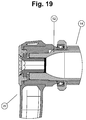
- FIG. 19 illustrates a left arm section hub detail view derived from FIG. 18 of a crank set with bottom bracket installed on a bicycle in accordance with some embodiments.
- FIG. 20 illustrates a method of installing a crank arm on a crank spindle in accordance with some embodiments.
- FIG. 21A illustrates a top section view of a right crank arm assembly in accordance with some embodiments.
- FIG. 21B illustrates a front view of a right crank arm assembly in accordance with some embodiments.
- FIG. 22A illustrates a top section view of a right crank arm assembly in accordance with some embodiments.
- FIG. 22B illustrates a front view of a right crank arm assembly in accordance with some embodiments.
- Embodiments of the invention are directed to a composite bicycle crank with an integral spindle attachment structure provides a unique method for attaching a bicycle crank arm to a bicycle crank spindle, and also for attaching a bicycle crank arm to a crank arm insert.
- a light-weight crank arm is able to be manufactured separately from the crank spindle or insert, and then securely attached after both pieces have been made. This allows for the pieces of the crank assembly to be manufactured from one or more different materials, and securely connected after manufacturing, to create a lower weight assembly than would be possible otherwise.
- a bicycle crank set and bottom bracket assembly 10 is installed in a bicycle frame bottom bracket assembly 12 .
- the bicycle crank set and bottom bracket assembly 10 are shown cut away from a complete bicycle frame.
- the bicycle frame bottom bracket assembly 12 comprising a bottom bracket shell 14 that comprises a left end 16 and a right end 18 .
- the crank set and bottom bracket assembly 10 comprises a left crank arm assembly 20 , a right crank arm assembly 22 , and one or more chain rings 24 .
- the crank set and bottom bracket assembly 10 also comprises a left bottom bracket cup assembly 26 and a right bottom bracket cup assembly 28 .
- the left bottom bracket cup assembly 26 and the right bottom bracket cup assembly 28 comprise a left bottom bracket cup 32 and a right bottom bracket cup 34 , a left bottom bracket ball bearing 36 and a right bottom bracket ball bearing 38 .
- the left bottom bracket ball bearing 36 includes a left inner race 40 , a left outer race 42 and a left bearing plurality of balls 44 between the races.
- the right bottom bracket ball bearing 38 includes a right inner race 46 , a right outer race 48 and a right bearing plurality of balls 50 between the races.
- the bicycle crank set and bottom bracket assembly 10 comprises a crank spindle 52 which is attached to right arm assembly 22 , and a left crank fastening bolt 54 which removably couples the left crank arm assembly 20 to the spindle 52 .
- the chain ring 24 is sandwiched between a right molded crank arm 82 and the chainring lock ring 25 .
- a right crank arm assembly 22 comprises a crank spindle 52 , a right crank arm 60 , and a right crank arm attachment screw 62 .
- the crank spindle 52 includes a left spindle end 64 , a right spindle end 66 , a left bearing race surface 68 , a right bearing race surface 70 , a left crank arm spindle torque coupling feature 72 , a right crank arm spindle torque coupling feature 74 , a torque coupling feature stop face 75 , a chainring attachment spline 76 , a lockring attachment thread 78 , and a right arm bolt threaded hole 80 .
- the right arm spindle torque coupling feature 74 comprises a round lobed spline interface.
- the right crank arm assembly 60 comprises a right molded crank arm 82 .
- the molded crank arm 82 comprises a right pedal hole 84 , a right arm spindle fastener counterbore 86 , a right arm spindle fastener counterbore pressure face 87 , and a right crank arm torque coupling feature 88 .
- the coupling feature comprise a spline.
- the right crank arm attachment screw 62 comprises a right crank arm attachment screw driving feature 90 , and a right crank arm attachment screw male thread 92 .
- FIG. 10 shows an exploded section view of the right crank arm assembly 60 .
- FIG. 10 also shows a left crank fastening bolt threaded hole 94 , and a crank spindle hollow bore 96 .
- FIG. 10 also shows a cross section view of a right molded crank arm 82 .
- the right molded crank arm 82 includes a right in-molded pedal insert 98 , which comprises a right pedal insert threaded hole 100 .
- the right molded crank arm 82 also comprises a right crank arm molded void 102 , and a right crank arm spindle end void 106 .
- the right crank arm attachment screw 92 comprises of a right crank arm attachment screw flange 108 , a right crank arm attachment screw flange pressure face 110 , and the right crank arm attachment screw male thread 92 .
- FIG. 10 also shows a spindle insert insertion distance 192 , and a right arm spindle pocket distance 194 .
- FIG. 12 shows a cross section of the right crank arm assembly 60 with the crank spindle 52 and right crank arm attachment screw 62 in their assembled positions relative to the right molded crank arm 82 .
- the right crank arm spindle bond surface 112 in its assembled and bonded position.
- the left crank arm assembly 20 comprises a left crank arm 116 , a left crank arm attachment screw 118 , a left crank arm insert attachment screw 120 and a left crank arm spindle attachment insert 122 .
- the left crank arm 116 comprises a left molded crank arm 124 , a left pedal hole 126 , a left arm spindle fastener counterbore 128 , and a left crank arm torque coupling feature 130 , in this case a spline is shown, and a left crank arm insert through hole 132 .
- the left crank arm spindle attachment insert 122 is comprised of a left arm insert torque coupling feature 134 , a left arm spindle attachment insert stop face 136 , a left arm spindle attachment insert end face 138 , a left arm spindle attachment insert internal thread 140 , a left arm spindle attachment insert through hole 142 , and a left arm spindle attachment insert screw press face 144 .
- the left arm insert torque coupling feature 134 comprises a round lobed spline interface.
- FIG. 15 shows an alternate view of the left crank arm assembly 20 , including a left molded crank arm 124 which is comprised of a left in-molded pedal insert 146 , which includes a left pedal insert threaded hole 148 .
- the left molded crank arm 124 also comprises a left crank arm molded void 150 , a left crank arm pedal end void 152 , a left crank arm spindle end void 154 , a left crank arm torque coupling feature 156 .
- the left molded crank arm 124 also includes a left arm torque coupling feature end face 158 , a left coupling feature through hole 160 , and a left arm outside counterbore pressure face 162 .
- FIG. 15 also shows a cross section of a left arm spindle attachment insert 122 , also comprising a left arm spindle insert torque coupling feature 164 , and a left arm spindle insert bearing stop face 166 .
- a left crank arm attachment screw 118 comprises a left arm attachment screw thread 168 , a left arm attachment screw pressure face 170 , a left arm attachment screw flange 172 , a left arm attachment screw extraction face 174 , and a left arm attachment screw torque driving feature 176 .
- FIG. 15 also shows a cross section of a left crank arm insert attachment screw 120 , which comprises a left insert attachment screw thread 178 , a left insert attachment screw compression face 180 , a left insert attachment screw internal driving feature 182 , a left insert attachment screw through hole 184 , and a left insert attachment screw extraction pressure face 186 , and a left insert attachment screw flange 188 .
- FIG. 15 further shows a left arm insert stop face 161 , a left arm insert insertion distance 196 , and a left arm spindle pocket distance 198 .
- FIG. 17 shows an alternate cross section view of a left crank arm assembly 20 in its assembled configuration.
- FIG. 19 shows a cross section detail view of a left crank arm assembly 20 attached to a crank spindle 52 in its operable configuration mounted to a bicycle bottom bracket assembly 14 .
- FIG. 20 shows a method of assembling either the left crank arm assembly 20 or right crank arm assembly 60 .
- the method begins in the step 2002 .
- the step 2004 one or more bonding surfaces of an insert and a crank arm are cleaned.
- adhesive is applied to one or more bonding surfaces of the insert and the crank arm and in the step 2008 the insert is slid into a receiving shape of the crank arm.
- a fastener is installed into the insert through a hole in a crank arm.
- torque is applied to the fastener and in the step 2014 the adhesive is cured.
- the method ends in the step 2016 .
- FIG. 21A-22B illustrate a right crank arm assembly in accordance with some embodiments.
- one or more spacers 200 are able to be used to adjust a chainline of a chain ring relative to the crank set.
- the one or more spacers 200 are able to comprise 1 mm spacers for adjusting the chainline.
- an adhesive is applied to the right crank arm spindle torque coupling feature 74 , and also applied to the right crank arm torque coupling feature 88 .
- the right crank arm spindle torque coupling feature 74 is then inserted into the right crank arm torque coupling feature 88 .
- the right crank arm attachment screw 62 is threaded into the right arm bolt threaded hole 80 , and the screw is tightened until the necessary assembly torque is achieved in the fastener.
- the spindle insert insertion distance 192 is shorter than the right arm spindle pocket distance 194 , such that when the screw is tightened, a compressive force is created in the right arm between the torque coupling feature stop face 75 and the right crank arm attachment screw flange pressure face 110 .
- first adhesive is applied to the left crank arm torque coupling feature 156 , and also applied to the left arm insert torque coupling feature 134 .
- the left arm insert torque coupling feature 134 is then inserted into the left crank arm torque coupling feature 156 .
- the left crank arm insert attachment screw 120 is threaded into the left arm spindle attachment insert internal thread 140 , and the screw is tightened until some designated assembly torque is achieved in the fastener.
- the left arm insert insertion distance 196 is shorter than the left arm spindle pocket distance 198 , such that when the screw is tightened, a compressive force is created in the left arm between the left arm outside counterbore pressure face 162 and the left arm insert stop face 161 .
- the left bottom bracket cup assembly 26 and the right bottom bracket cup assembly 28 are installed on the bicycle frame.
- these bottom bracket cup assemblies are threaded into the frame, or pressed into place, etc.
- bearings may be fitted directly into the frame using appropriately sized pockets in the bottom bracket assembly or analogous bicycle frame area.
- a chain ring 24 is installed on the crank spindle 22 , and a chainring lock ring 25 is used to retain the chain ring 24 on the chainring attachment spline 76 .
- the spindle is passed through the bottom bracket bearings so that the left crank arm spindle torque coupling feature 72 is exposed on the left side of the left bottom bracket cup assembly 26 , and the right crank arm assembly 22 presses against the right inner race 46 of the right bottom bracket cup assembly 28 .
- the chainring lock ring 25 contacts the right inner race 46 , and acts as a stop for the right crank arm assembly 22 .
- the left crank arm assembly 20 is attached to the crank spindle 22 using the crank fixing bolt 54 .
- the crank/spindle assembly is a net fit between the left inner race 40 and the right inner race 46 .
- the tolerance in the spindle interface may be taken up by a bearing preload device such as a wave spring, or a threaded preload mechanism, a compliant washer, or some other method.
- the left crank arm assembly 20 is attached to the crank spindle 22 through an integral attachment structure and the right crank arm assembly 60 is attached to a spindle insert, where the chain ring 24 is attached to the right crank arm assembly 60 and the demountable spindle interface is on the same side of the bicycle as the chain ring.
- the composite bicycle crank with an integral spindle and attachment structure as described above and shown in the illustrations uses a round lobed spline as the interface between the spindle and the right arm structure, and between the bonded insert and the left arm structure.
- the spline is able to comprise any number of other shapes, including a circular square or triangular shaped profile, a square toothed spline, and involute spline, a tri-lobe or four lobed polygon type shape, or any other straight geometric shape.
- connection between the left crank arm assembly and the spindle could be a splined interface, a tapered square interface, or some alternative torque transmitting coupling.
- the interface between the spindle or insert and arm structures is able to be created with a taper to the shape from one end of the profile to the other, or a partial straight profile with a tapered profile on the lead-in end.
- a similar structure as is used to connect the crank arms to the spindle and inserts could be used to connect a pedal inset to a crank arms.
- a shaped sleeve area would be molded or formed into the pedal end of the crank arm piece, and an insert and threaded fastener would be used to hold the insert in place, while the insert is bonded to the arm with adhesive. This could form a light-weight and strong interface between, for instance, a metal pedal insert and a plastic composite crank arm.
- the molded crank arm is constructed using any number of material molding or forming technologies.
- the arm could be formed using molded carbon-fibers in an epoxy resin or thermoplastic resin, short carbon or glass fibers injection molded using any number of moldable resins.
- the arms could also be forged or cast from light metal alloys, such as magnesium, aluminum or titanium and their alloys.
- crank arms could be made from a solid, low cost piece of reinforced plastic in order to make a low-cost crank assembly.
- a metal spindle or insert could be used to provide necessary strength where needed to the assembly.
- the hollow crank arms could be formed from two pieces of sheet metal, which would them be seam welded together to form a hollow structure, or bonded together.
- a hollow arm structure could be composed of two pieces of dissimilar material and then bonded together to form a light hollow structure, which would then be bonded to the spindle and insert structures as described.
- two half-spindles are able to be substituted for the single full-length spindle in the preferred embodiment, with a torque transmitting connection included where the two half spindles meet near the centerline of the bicycle.
- the two spindle stubs would connect to the crank arms with the same structure described in the preferred embodiment.
- the crank assembly such as described above is used with a crank set comprising a toothed pulley for use with a belt drive.
- a gear or gear coupling for use with a gearbox drive to propel the bicycle.
- the attachment method for the crank spindle to the drive side crank arm may be used for mounting either a spindle of the drive side crank spindle attachment, or to attach a de-mountable interface, as shown on the non-drive-side crank arm.
- a single molded plastic composite arm for use on both the drive and non-drive side crank arms, rather than differently shaped arms for each side of the assembly. Consequently, a single mold is able to be used to form both arms, saving time and cost.
- Another advantage of the novel composite bicycle crank with an integral spindle attachment structure is that it allows a hollow crank arm to be manufactured separately from the crank spindle, using different materials for each, and attaching them together after manufacture to create a structure that is lightweight and strong.
- a further advantage of the novel composite bicycle crank with an integral spindle attachment structure is that it allows for hollow areas to be designed into a composite crank arm surrounding the attachment point for the spindle, resulting in a lighter and stronger finished product. Additionally, the composite bicycle crank with an integral spindle attachment structure separates the attachment point for a chainring or chainring spider from the crank arm structure, so that splined features and threads may be included on a spindle made of a suitable metal alloy, as threads and narrow splines are not easy to manufacture in plastic composite materials, but are easy to manufacture using suitable metal alloys.
- the area surrounding the spindle attachment may be formed without a metal insert, allowing the structure to be stronger and lighter than if an insert is molded into the structure during fabrication of the arm.
- the composite bicycle crank with an integral spindle attachment structure as described herein has many advantages.
Abstract
Description
Claims (25)
Priority Applications (2)
| Application Number | Priority Date | Filing Date | Title |
|---|---|---|---|
| US15/462,359 US11142280B2 (en) | 2016-03-24 | 2017-03-17 | Bicycle crank with spindle attachment structure |
| TW106109159A TWI759288B (en) | 2016-03-24 | 2017-03-20 | Bicycle crank set, bicycle crank arm, and method of installing a first crank arm and a second crank arm on a crank spindle |
Applications Claiming Priority (2)
| Application Number | Priority Date | Filing Date | Title |
|---|---|---|---|
| US201662313024P | 2016-03-24 | 2016-03-24 | |
| US15/462,359 US11142280B2 (en) | 2016-03-24 | 2017-03-17 | Bicycle crank with spindle attachment structure |
Publications (2)
| Publication Number | Publication Date |
|---|---|
| US20170274960A1 US20170274960A1 (en) | 2017-09-28 |
| US11142280B2 true US11142280B2 (en) | 2021-10-12 |
Family
ID=59896530
Family Applications (1)
| Application Number | Title | Priority Date | Filing Date |
|---|---|---|---|
| US15/462,359 Active US11142280B2 (en) | 2016-03-24 | 2017-03-17 | Bicycle crank with spindle attachment structure |
Country Status (5)
| Country | Link |
|---|---|
| US (1) | US11142280B2 (en) |
| EP (1) | EP3419887A4 (en) |
| CN (1) | CN109689489B (en) |
| TW (1) | TWI759288B (en) |
| WO (1) | WO2017165226A1 (en) |
Cited By (3)
| Publication number | Priority date | Publication date | Assignee | Title |
|---|---|---|---|---|
| US11351815B2 (en) | 2017-08-21 | 2022-06-07 | The Hive Global, Inc. | Bicycle cassette with clamping connection |
| US11485449B2 (en) | 2015-09-01 | 2022-11-01 | The Hive Global, Inc. | Bicycle cassette with locking connection |
| US11932351B2 (en) | 2020-07-17 | 2024-03-19 | The Hive Global, Inc. | Conical bicycle cassette sprocket structure |
Families Citing this family (11)
| Publication number | Priority date | Publication date | Assignee | Title |
|---|---|---|---|---|
| US8820192B2 (en) | 2009-04-29 | 2014-09-02 | Race Face Prerformance Products Inc. | Bicycle crank arm and insert therefore |
| US10221887B2 (en) | 2012-12-06 | 2019-03-05 | The Hive Global, Inc | Self locking bearing preload adjuster |
| CN112517887A (en) | 2016-04-11 | 2021-03-19 | 福克斯制造有限公司 | Method for forming a bicycle front sprocket assembly |
| ES2600778B1 (en) * | 2016-10-20 | 2017-09-12 | Rotor Componentes Tecnológicos,S.L. | BICYCLE Crankset |
| US10000253B1 (en) * | 2016-11-25 | 2018-06-19 | Shimano Inc. | Bicycle crank assembly |
| US11014628B2 (en) * | 2017-04-28 | 2021-05-25 | Fox Factory, Inc. | Cinch direct mount 2X ring system |
| US11359709B2 (en) * | 2018-12-18 | 2022-06-14 | Fox Factory, Inc. | Chainring |
| US11680633B2 (en) * | 2019-02-08 | 2023-06-20 | Fox Factory, Inc. | Chainring |
| TWI809568B (en) * | 2020-11-20 | 2023-07-21 | 美商福克斯制造有限公司 | A hybrid assembly and a bicycle crank arm assembly |
| US20230330475A1 (en) * | 2022-04-18 | 2023-10-19 | Xiamen Evere Sports Goods Co., Ltd. | Crank for fitness equipment with self-locking mechanism |
| CN117620646B (en) * | 2024-01-26 | 2024-04-05 | 江苏联星机械科技有限公司 | Diesel engine crankshaft press-fitting tool |
Citations (424)
| Publication number | Priority date | Publication date | Assignee | Title |
|---|---|---|---|---|
| US512729A (en) | 1894-01-16 | Harry lucas and james archer | ||
| US527384A (en) | 1894-10-09 | Bicycle-pedal | ||
| US527520A (en) | 1894-10-16 | copeland | ||
| US547639A (en) | 1895-10-08 | Bicycle-pedal | ||
| US575712A (en) | 1897-01-26 | Richard f | ||
| US576548A (en) | 1897-02-09 | Bicycle-pedal | ||
| US579479A (en) | 1897-03-23 | E morris petehs co | ||
| US590685A (en) | 1897-09-28 | Half to agnes jardine | ||
| US595388A (en) | 1897-12-14 | Bicycle-pedal attachment | ||
| US598325A (en) | 1898-02-01 | Gomeey mcintyre | ||
| US614900A (en) | 1898-11-29 | Velocipede-pedal | ||
| US616167A (en) | 1898-12-20 | James ernest a | ||
| US620266A (en) | 1899-02-28 | Julius wodiska | ||
| US658400A (en) | 1899-11-27 | 1900-09-25 | Straight Mfg Company | Crank-hanger. |
| US666679A (en) | 1897-10-07 | 1901-01-29 | Stearns Bicycle Agency | Velocipede-pedal. |
| US1070971A (en) | 1912-07-17 | 1913-08-19 | Robert Todd Lowd | Pedal. |
| US1325206A (en) | 1919-12-16 | Driving-gear casing eor bicycles | ||
| US1400131A (en) | 1921-02-05 | 1921-12-13 | Howard A Jones | Sprocket-guard attachment for bicycles |
| US1535601A (en) | 1924-06-09 | 1925-04-28 | James H Graham | Pedal for bicycles |
| US1636327A (en) | 1926-05-12 | 1927-07-19 | Colson Company | Cycle |
| US2015430A (en) * | 1935-03-02 | 1935-09-24 | Int Motor Co | Involute spline shaft |
| US2024499A (en) | 1933-04-13 | 1935-12-17 | Baron Johannes | Bicycle pedal |
| US2228770A (en) * | 1938-08-19 | 1941-01-14 | Letourneau Inc | Shaft and hub mounting |
| US2317070A (en) * | 1941-12-23 | 1943-04-20 | Letourneau Inc | Shaft and hub connection |
| US2567785A (en) | 1948-01-09 | 1951-09-11 | Rieger Mfg Company | Pedal for bicycles or the like |
| US2568443A (en) | 1948-09-22 | 1951-09-18 | Gerner Willi | Bicycle pedal |
| US2751797A (en) | 1952-06-18 | 1956-06-26 | Darwin Products Inc | Built-up pedal construction |
| US3185439A (en) | 1962-08-01 | 1965-05-25 | Fujitsu Ltd | Hydraulic motor control system |
| US3184993A (en) | 1963-12-11 | 1965-05-25 | Carl A Swenson | Derailleur guard |
| GB1031337A (en) | 1964-02-13 | 1966-06-02 | Benjamin George Bowden | An improved vehicle frame |
| US3303720A (en) | 1963-11-20 | 1967-02-14 | Motobecane Ateliers | Folding pedal for bicycles and the like |
| US3382734A (en) | 1966-09-16 | 1968-05-14 | Ashtabula Bow Socket Company | Bicycle pedal |
| US3416385A (en) | 1967-03-20 | 1968-12-17 | Case Co J I | Sprocket assembly |
| US3477303A (en) | 1967-11-28 | 1969-11-11 | Schwinn Bicycle Co | Double plateau sprocket assembly |
| US3485113A (en) | 1966-07-19 | 1969-12-23 | Raleigh Industries Ltd | Pedals |
| US3592076A (en) | 1969-06-03 | 1971-07-13 | Ashtabula Bow Socket Co | Plastic bicycle pedal with a foot strap means |
| GB1281731A (en) | 1969-06-25 | 1972-07-12 | Raleigh Industries Ltd | A cycle frame |
| US3760653A (en) | 1971-03-12 | 1973-09-25 | Union Sils Van De Loo & Co | Pedal for bicycles |
| US3785129A (en) | 1971-11-01 | 1974-01-15 | Purolator Inc | Spin-on air filter |
| US3807255A (en) | 1969-06-03 | 1974-04-30 | Ashtabula Bow Socket Co | Plastic bicycle pedal |
| US3811339A (en) | 1972-08-17 | 1974-05-21 | Union Sils Van De Loo & Co | Pedal for bicycles and similar vehicles |
| GB1361394A (en) | 1971-07-29 | 1974-07-24 | Raleigh Industries Ltd | Cycle frame |
| US3869138A (en) | 1973-04-04 | 1975-03-04 | Ford Motor Co | Steering device having a chain operated steering gear actuator |
| US3910136A (en) | 1973-04-16 | 1975-10-07 | Lucien Charles Hippolyte Juy | Protection apparatus for a speed change mechanism of a bicycle or similar vehicle |
| US3933373A (en) | 1973-04-10 | 1976-01-20 | Niels Gammelgaard | Bicycle having arched mounting tube for the steering member |
| GB1431308A (en) | 1972-12-29 | 1976-04-07 | Original Plastic Bike | Bicycle frame |
| US3964343A (en) | 1975-06-09 | 1976-06-22 | Lauterbach James H | Combination means for rigidly attaching shoe to a pedal for a foot-driven crank-operated machine |
| US3973447A (en) | 1974-06-06 | 1976-08-10 | Shimano Industrial Company, Limited | Derailleur for a bicycle |
| US4016357A (en) | 1975-07-18 | 1977-04-05 | Burroughs Corporation | Floor structure for the environment of a modular computer system |
| US4044621A (en) | 1975-06-09 | 1977-08-30 | Mcgregor Sr John C | Sprocket structure and chain guard |
| US4078444A (en) | 1976-02-13 | 1978-03-14 | Jacques Andre Huret | Front derailleur chain guide |
| US4089236A (en) | 1975-05-13 | 1978-05-16 | Claude Genzling | Safety connection between bicycle pedal and shoe |
| US4093325A (en) | 1975-10-30 | 1978-06-06 | Societe Nouvelle De Roulements | Tubular spindle mounting for bicycle bottom-bracket hub |
| US4135727A (en) | 1976-07-06 | 1979-01-23 | Tullio Campagnolo | Mounting of the transmission chain of bicycles |
| US4237743A (en) | 1977-10-11 | 1980-12-09 | Shimano Industrial Company, Limited | Front derailleur for a bicycle |
| US4240303A (en) | 1978-09-27 | 1980-12-23 | Mosley Earnest D | Chain sprocket with opposite frangible side guide plates |
| US4269084A (en) | 1978-08-11 | 1981-05-26 | Shimano Industrial Company, Limited | Toe clip for a bicycle pedal |
| US4298210A (en) | 1979-02-21 | 1981-11-03 | Jacques Lotteau | Device allowing a safety connection between the pedal of a bicycle and the shoe worn by the cyclist |
| US4302987A (en) | 1978-11-11 | 1981-12-01 | Shimano Industrial Company, Limited | Pedal for bicycle |
| US4330137A (en) | 1979-08-15 | 1982-05-18 | Shimano Industrial Company Limited | Front derailleur for a bicycle |
| US4337933A (en) | 1979-04-25 | 1982-07-06 | Shimano Industrial Company Limited | Jig for mounting a front derailleur in a bicycle |
| US4377952A (en) | 1979-09-10 | 1983-03-29 | Sarragan S.A. | Pedal block for a cycle shoe |
| US4380445A (en) | 1974-08-16 | 1983-04-19 | Shimano Industrial Company Limited | Transmission for a bicycle |
| US4398434A (en) | 1980-03-12 | 1983-08-16 | Senkichiro Kimura | Force-saving high speed pedal |
| US4433963A (en) | 1979-12-29 | 1984-02-28 | Shimano Industrial Company Limited | Chain guide for a derailleur for a bicycle |
| US4439172A (en) | 1977-12-28 | 1984-03-27 | Shimano Industrial Company Limited | Chain gear and crank mounting assembly |
| US4441383A (en) | 1978-06-12 | 1984-04-10 | Shimano Industrial Company Limited | Gear crank for a bicycle |
| US4442732A (en) | 1978-09-22 | 1984-04-17 | Shimano Industrial Company Limited | Pedal for a bicycle |
| US4445289A (en) | 1981-06-23 | 1984-05-01 | Patrick S.A. | Plastic spike for sports shoe |
| US4445397A (en) | 1980-08-25 | 1984-05-01 | Shimano Industrial Company Limited | Foot conforming pedal for a bicycle |
| US4472163A (en) | 1979-11-07 | 1984-09-18 | Societe Italiana Catene Calibrate Regina S.P.A. | Multi-gear free wheel assembly for derailleurs for bicycles |
| US4475894A (en) | 1981-05-27 | 1984-10-09 | Sugino Cycle Industries, Ltd. | Front sprocket wheel having chain guard for bicycles |
| US4487424A (en) | 1983-01-21 | 1984-12-11 | Ellis William L | Bicycle sprocket shield |
| US4488453A (en) | 1981-02-13 | 1984-12-18 | Drugeon Jean Francois | Bicycle pedal for coupling a shoe in preset position, and a cyclist's shoe fitted to said pedal |
| US4498890A (en) | 1982-12-20 | 1985-02-12 | General Electric Company | Fixed track chain drive |
| US4507105A (en) | 1982-12-09 | 1985-03-26 | Huffy Corporation | Bicycle chainguard |
| US4506463A (en) | 1982-02-22 | 1985-03-26 | Adidas Fabrique De Chassures De Sport | Pedal block for cycle shoes |
| US4515386A (en) | 1983-06-27 | 1985-05-07 | Kanji Tsujimura | Guard for chain wheel |
| US4523492A (en) | 1980-12-28 | 1985-06-18 | Shimano Industrial Company Limited | Pedal for a bicycle |
| US4538480A (en) | 1983-07-01 | 1985-09-03 | Trindle James J | Bicycle pedal and shoe |
| US4548422A (en) | 1981-11-17 | 1985-10-22 | Manufacture Industrielle De Cycles Et Motocycles - M.I.C.M.O. | Bicycle frame having an assembled-unit shell structure |
| US4573950A (en) | 1983-06-24 | 1986-03-04 | Shimano Industrial Company Limited | Chain guide in a front derailleur |
| US4608878A (en) | 1980-08-18 | 1986-09-02 | Shimano Industrial Company Limited | Reduced-weight gear crank |
| US4632416A (en) | 1985-07-24 | 1986-12-30 | Zelenetz Scott H | Flexible protective cover for the drive train elements of a bicycle |
| US4639240A (en) | 1985-05-01 | 1987-01-27 | Schwinn Bicycle Company | Chainguard |
| US4640151A (en) | 1984-02-27 | 1987-02-03 | Howell Richard J | Bicycle pedalling apparatus |
| US4646586A (en) | 1984-06-01 | 1987-03-03 | Antonio Rapisarda | Device for connecting a bicycle pedal to a cycling shoe |
| US4662862A (en) | 1986-01-22 | 1987-05-05 | Les Matson | Tensioning device for flexible drive element |
| US4665767A (en) | 1982-08-31 | 1987-05-19 | Jakob Lassche | Bicycle pedal with foot holder |
| US4686867A (en) | 1983-12-16 | 1987-08-18 | Ste Look | Bicycle pedal and shoe fastening combination |
| US4704919A (en) | 1984-11-28 | 1987-11-10 | Durham Roger O | Two-piece crankshaft for bicycles |
| US4735107A (en) | 1983-09-28 | 1988-04-05 | John Winkie | Pedal arrangement |
| USD298613S (en) | 1986-02-24 | 1988-11-22 | Wald Manufacturing Co., Inc. | Bicycle chain guard |
| US4791692A (en) | 1986-06-06 | 1988-12-20 | Collins Roy S | Studs for articles of footwear |
| US4803894A (en) | 1984-02-27 | 1989-02-14 | The Shelburne Corporation | Bicycle pedalling apparatus |
| US4811626A (en) | 1986-10-31 | 1989-03-14 | Michel Bezin | Bicycle pedal crank |
| US4815333A (en) | 1987-02-19 | 1989-03-28 | Sampson Sports, Inc. | Integrated bicycle pedal with self centering and lateral release capabilities |
| US4827633A (en) | 1986-05-27 | 1989-05-09 | Feldstein Frank I | Retractable bicycle shoe cleat |
| US4832667A (en) | 1987-08-06 | 1989-05-23 | Wren Nicholas D | Front chain wheel chain guide |
| US4838115A (en) | 1987-04-30 | 1989-06-13 | Shimano Industrial Company Limited | Pedal for a bicycle |
| US4840085A (en) | 1986-01-23 | 1989-06-20 | Shimano Industrial Company Limited | Pedal for a bicycle |
| US4854924A (en) | 1986-08-21 | 1989-08-08 | Shimano Industrial Company Limited | Cover device for a driving chain for a bicycle |
| US4856801A (en) | 1987-12-16 | 1989-08-15 | Cycle Composites, Inc. | Integral rear wheel suspension for composite material bicycle frame |
| WO1989008039A1 (en) | 1988-03-02 | 1989-09-08 | Bivaco A.S. | Bicycle |
| US4873890A (en) | 1987-09-14 | 1989-10-17 | Shimano Industrial Company Limited | Pedal for a bicycle |
| US4882946A (en) | 1984-05-18 | 1989-11-28 | Beyl Jean J | Pedal for a bicycle or similar device |
| US4893523A (en) | 1988-01-07 | 1990-01-16 | Lennon Dan C | Bicycle and pedal system |
| US4898063A (en) | 1987-02-19 | 1990-02-06 | Sampson Sports, Inc. | Integrated bicycle pedal with self centering and lateral release capabilities |
| US4900050A (en) | 1988-10-18 | 1990-02-13 | Huffy Corporation | Manufacture of bicycle frames |
| US4905541A (en) | 1988-09-29 | 1990-03-06 | Huffy Corporation | Derailleur guard |
| US4923324A (en) * | 1989-07-03 | 1990-05-08 | Eastman Kodak Company | Zero clearance coupler for connecting a driving member to a splined hub |
| US4928549A (en) | 1987-09-10 | 1990-05-29 | Shimano Industrial Company Limited | Pedal for a bicycle |
| GB2225296A (en) | 1988-11-24 | 1990-05-30 | David Lindfield | Bicycle crank |
| US4932287A (en) | 1988-11-07 | 1990-06-12 | Dennis Ramos | Combined shoe and pedal for sports bicycle |
| US4947708A (en) | 1988-07-28 | 1990-08-14 | BG Innovations (Societe a Responsabilite Limitee de Droit Francais) | Bicycle pedal |
| US4986949A (en) | 1986-05-12 | 1991-01-22 | Trimble Brent J | Method of making composite bicycle frames |
| US5002520A (en) | 1989-12-14 | 1991-03-26 | Greenlaw John W | Bicycle drive chain guide |
| US5003841A (en) | 1988-08-12 | 1991-04-02 | Shimano Industrial Co., Ltd. | Bicycle pedal |
| US5014571A (en) | 1988-10-05 | 1991-05-14 | Geze Sport International Gmbh | Bicycle pedal with a releasable binding |
| US5019312A (en) | 1988-10-18 | 1991-05-28 | Huffy Corporation | Method for assembling a bicycle frame |
| US5018564A (en) | 1990-03-26 | 1991-05-28 | Anglin Gregory V | Fabric protective cover for a drive mechanism of a bicycle |
| DE4002574A1 (en) | 1990-01-30 | 1991-08-01 | Kugelfischer G Schaefer & Co | Bicycle pedal crank with axis - are integrally die cast, with axis as hollow journal |
| US5046382A (en) | 1990-02-20 | 1991-09-10 | Steinberg John D | Clipless bicycle pedal system |
| US5048369A (en) | 1990-02-28 | 1991-09-17 | Chen Chung I | Clipless pedal with fastening means |
| US5060537A (en) | 1988-09-09 | 1991-10-29 | Shimano Industrial Co., Ltd. | Bicycle pedal and clamping device therefor |
| US5067930A (en) | 1990-12-20 | 1991-11-26 | Robert Morales | Bicycle sprocket protector |
| USD323309S (en) | 1989-02-17 | 1992-01-21 | Perry Paul L | Bicycle freewheel gear cover |
| US5115692A (en) | 1988-11-09 | 1992-05-26 | Shimano Inc. | Bicycle pedal |
| US5121935A (en) | 1991-01-18 | 1992-06-16 | Mathieu Francis X | Readily removable and collapsible bicycle fender |
| US5125288A (en) | 1991-01-22 | 1992-06-30 | Amiet Alick G | Arcuate bicyle crank lever apparatus |
| CN2115968U (en) | 1991-11-30 | 1992-09-16 | 汤金荣 | Dual-speed bicycle with two-teeth plate rear sprocket wheel |
| US5179873A (en) | 1991-09-09 | 1993-01-19 | Ocean State International, Inc. | Bicycle crank assembly |
| US5188384A (en) | 1989-11-20 | 1993-02-23 | Look S.A. | Bicycle frame |
| US5194051A (en) | 1991-03-27 | 1993-03-16 | Shimano, Inc. | Sprocket wheel mounting unit for a bicycle |
| US5195397A (en) | 1990-11-13 | 1993-03-23 | Shimano, Inc. | Bicycle pedal having two surfaces for fixing a cleat |
| US5203229A (en) | 1992-04-28 | 1993-04-20 | Chen Chung I | Quick-release clipless pedal with two cleat engaging sides |
| US5207768A (en) * | 1990-04-16 | 1993-05-04 | Eaton Corporation | Transmission thrust washer and locking means therefor |
| US5209581A (en) * | 1990-11-14 | 1993-05-11 | Shimano, Inc. | Crank arm mounting apparatus for a bicycle |
| US5215322A (en) | 1991-12-10 | 1993-06-01 | Enders Mark L | Dual and single seat composite bicycle frames and fabrication methods therefore |
| US5259270A (en) | 1992-12-30 | 1993-11-09 | Lin Wen Hwa | Bicycle pedal |
| CN1080902A (en) | 1993-04-22 | 1994-01-19 | 沈激 | Labour-saving pedal crank |
| AT397641B (en) | 1989-12-21 | 1994-05-25 | Benes Alois | Pedal crank drive |
| US5320582A (en) | 1991-11-29 | 1994-06-14 | Nec Corporation | Chain driving unit |
| CN2169593Y (en) | 1993-04-05 | 1994-06-22 | 张宝全 | Two speed flying wheel |
| CN2170254Y (en) | 1993-04-05 | 1994-06-29 | 于东明 | Full-plastic bicycle |
| US5326331A (en) | 1993-08-26 | 1994-07-05 | Hallock Iii Orrin S | Chain, hub, spoke and derailleur guard |
| CN2183329Y (en) | 1994-02-22 | 1994-11-23 | 上海万国车辆配件有限公司 | External speed-changing free wheel for bicycle |
| JPH072157A (en) | 1993-03-16 | 1995-01-06 | Pierre A Martin | Bicycle frame |
| US5379665A (en) | 1991-06-19 | 1995-01-10 | Shimano Inc. | Bicycle pedal |
| CN2188541Y (en) | 1994-03-18 | 1995-02-01 | 唐翰章 | Crank of bicycle |
| USD355872S (en) | 1993-12-29 | 1995-02-28 | Huffy Corporation | Bicycle chainguard |
| US5419218A (en) | 1992-11-04 | 1995-05-30 | Campagnolo S.R.L. | Safety pedal for bicycles and the like |
| US5423233A (en) | 1992-02-27 | 1995-06-13 | Look S.A. | Device for attaching a shoe on a bicycle |
| US5435869A (en) | 1993-08-27 | 1995-07-25 | Christensen; Roland | Method for manufacturing a composite crank arm |
| CN2206250Y (en) | 1995-01-04 | 1995-08-30 | 梁宗泰 | Flywheel force-combination structure for locating upper chain |
| US5451071A (en) | 1993-09-16 | 1995-09-19 | Cannondale Corporation | Bicycle frame |
| US5460576A (en) | 1993-10-07 | 1995-10-24 | Barnett; Robert L. | Bicycle chain guide |
| CN2210849Y (en) | 1994-11-25 | 1995-10-25 | 陈宝亮 | Hollow crank for bicycle |
| WO1996003306A1 (en) | 1994-07-22 | 1996-02-08 | Royal Melbourne Institute Of Technology | Bicycle frames |
| DE29600548U1 (en) | 1996-01-13 | 1996-02-29 | Thun Alfred & Co Gmbh | Pedal crank for a bike |
| US5496222A (en) | 1993-11-12 | 1996-03-05 | Shimano, Inc. | Front derailleur for a bicycle |
| US5497680A (en) | 1990-07-09 | 1996-03-12 | Shimano Inc. | Apparatus for securing a shoe to a bicycle pedal |
| US5505111A (en) | 1989-11-14 | 1996-04-09 | Shimano Inc. | Connecting structure between bicycle pedal and cleat, bicycle pedal and cleat |
| US5540118A (en) | 1994-05-09 | 1996-07-30 | Calendrille, Jr.; John L. | Flexible bicycle derailleur cover for protection against contaminants such as mud |
| US5544907A (en) | 1995-03-31 | 1996-08-13 | Industrial Technology Research Institute | Composite bicycle frame with y shaped tubular configuration |
| US5549396A (en) | 1995-05-16 | 1996-08-27 | Chiang; Douglas | Bicycle crank axle |
| TW284731B (en) | 1995-08-25 | 1996-09-01 | Gt Bicycle Inc | Composite bicycle frame and method of manufacture |
| SK103295A3 (en) | 1994-11-07 | 1996-10-02 | Mora Moravia A S | Pedal crank |
| US5626060A (en) | 1996-06-26 | 1997-05-06 | Lin; Wen-Hwa | Bicycle bottom bracket and bearing axle arrangement |
| US5632940A (en) | 1994-03-29 | 1997-05-27 | Whatley; Bradford L. | Method of making an integrally stiffened article |
| US5644953A (en) | 1995-09-12 | 1997-07-08 | Cyclone Precision, Inc. | Crank assembly for a bicycle |
| DE19601125A1 (en) | 1996-01-13 | 1997-07-17 | Thun Alfred & Co Gmbh | Pedal crank for a bicycle |
| US5676616A (en) | 1996-03-06 | 1997-10-14 | Shimano, Inc. | Protective cover for a bicycle derailleur |
| US5679084A (en) | 1996-05-06 | 1997-10-21 | Daniels, Iii; Vernon James | Motorcycle roller chain guide |
| US5687619A (en) | 1994-04-29 | 1997-11-18 | Bryne; Richard M. | Clipless bicycle pedal |
| US5725450A (en) | 1996-08-21 | 1998-03-10 | Joshua Paris | Device for preventing derailment of a bicycle chain |
| US5727429A (en) | 1996-08-26 | 1998-03-17 | Shimano, Inc. | Low profile bicycle pedal and cleat assembly |
| US5728018A (en) | 1994-11-25 | 1998-03-17 | Shimano, Inc. | Method and apparatus for positioning a bicycle derailleur chain guide |
| CN2277928Y (en) | 1996-09-12 | 1998-04-08 | 陈逢文 | Gear disc crank for bicycle |
| CN2279303Y (en) | 1996-06-18 | 1998-04-22 | 周祯祥 | Quick small-size foldable and variable speed bicycle |
| US5765450A (en) | 1994-10-21 | 1998-06-16 | Kruger; Andre L. | Bicycle pedal |
| EP0849155A2 (en) | 1996-12-20 | 1998-06-24 | Shimano Inc. | Multiple sprocket assembly for a bicycle |
| EP0849154A2 (en) | 1996-12-20 | 1998-06-24 | Shimano Inc. | Hollow crank spindle unit for bicycles |
| US5771757A (en) | 1996-01-19 | 1998-06-30 | Shimano, Inc. | Clipless bicycle pedal with large shoe-contacting area |
| US5782714A (en) | 1997-01-27 | 1998-07-21 | Evergreen Innovations, L.L.C. | Bicycle chain guide |
| US5791202A (en) | 1995-12-27 | 1998-08-11 | Karsdon; Jeffrey | Tetrahelical/curved bicycle crank-arm connecting rod for human/mechanical powered machines and the like |
| US5806379A (en) | 1991-05-30 | 1998-09-15 | Shimano, Inc. | Bicycle pedal system having variable tread surfaces |
| US5809844A (en) | 1996-10-30 | 1998-09-22 | Durham; Roger O. | Spacing ring for bicycle chainrings |
| US5819599A (en) | 1995-08-04 | 1998-10-13 | Shimano, Inc. | Bicycle crank arm parts/assembly and assembly tools |
| US5846148A (en) | 1995-08-07 | 1998-12-08 | Shimano, Inc. | Bicycle front derailleur |
| US5893299A (en) | 1996-12-20 | 1999-04-13 | Shimano Inc. | Bicycle crank arm |
| DE19751879A1 (en) * | 1997-11-22 | 1999-05-27 | Sram De Gmbh | Pedal bearing unit for bicycle |
| DE19755950A1 (en) | 1997-12-16 | 1999-06-24 | Jason Chen | Molding bicycle pedal crank |
| US5927155A (en) | 1996-12-31 | 1999-07-27 | Jackson; Emmitt K. | Bicycle pedal |
| US5941135A (en) | 1997-06-18 | 1999-08-24 | Schlanger; Raphael | Bicycle crankshaft assembly |
| WO1999054193A1 (en) | 1998-04-22 | 1999-10-28 | Jeffrey Karsdon | Tetrahelical/curved bicycle crank arm/connecting rod |
| US6003889A (en) | 1994-09-12 | 1999-12-21 | Shalom; Saeed Solomon | Simple drive assembly for bicycles with a plain axle containing larger and more durable bearings |
| FR2780698A1 (en) | 1998-07-03 | 2000-01-07 | Mavic Sa | Pedal crank axle for bicycle |
| US6014914A (en) | 1998-11-05 | 2000-01-18 | Shimano Inc. | Bicycle pedal |
| US6014913A (en) | 1996-12-27 | 2000-01-18 | Shimano, Inc. | Hollow crank spindle unit for bicycles |
| EP0898542B1 (en) | 1996-05-14 | 2000-04-19 | Markus Storck | Bicycle crank |
| US6059171A (en) | 1995-08-04 | 2000-05-09 | Shimano, Inc. | Bicycle crank and manufacturing method |
| US6058803A (en) | 1996-12-27 | 2000-05-09 | Shimano, Inc. | Hollow bicycle crank and method for manufacturing same |
| US6060982A (en) | 1998-04-27 | 2000-05-09 | Holtrop; Perryn H. J. | Bicycle anti-theft alarm system |
| US6059378A (en) * | 1997-05-01 | 2000-05-09 | Impact Forge, Inc. | Taperlock axle apparatus and flange |
| US6083132A (en) | 1998-05-04 | 2000-07-04 | Moxee Innovations Corporation | Free floating belt idler |
| US6095691A (en) | 1999-04-23 | 2000-08-01 | Chiang; Douglas | Crank axle for bicycle |
| US6117032A (en) | 1998-02-13 | 2000-09-12 | Shimano, Inc. | Protective plate for bicycle chain |
| NL1015666C1 (en) | 2000-07-10 | 2000-11-13 | Mattheus Bernardus Van Dijk | Bicycle with left and right frame members that bolt together to form hollow, rigid, monocoque shell to enclose chain drive |
| CN2409136Y (en) | 1999-12-28 | 2000-12-06 | 凯特工业股份有限公司 | Bicycle crank |
| CN2409135Y (en) | 1999-12-28 | 2000-12-06 | 凯特工业股份有限公司 | Improved bicycle crank |
| US6165092A (en) | 1996-09-18 | 2000-12-26 | Bramham; Benjamin | Guide assembly for a bicycle |
| US6203459B1 (en) | 1997-07-25 | 2001-03-20 | John L. Calendrille, Jr. | Bicycle derailleur system with integral flexible seal to protect moving parts from contaminants |
| CN2428396Y (en) | 2000-06-13 | 2001-05-02 | 凯特工业股份有限公司 | Bicycle crank with hollow slot |
| CN2434218Y (en) | 2000-06-16 | 2001-06-13 | 徐国松 | Crank of light-weight bicycle |
| US6264575B1 (en) | 1999-04-08 | 2001-07-24 | Shimano, Inc. | Freewheel for a bicycle |
| US6266990B1 (en) | 2000-09-06 | 2001-07-31 | William Blair Shook | Method for integrally manufacturing an one-piece forged hollow crank of a bicycle |
| TW448114B (en) | 2000-06-12 | 2001-08-01 | Advanced Int Multitech Co Ltd | Manufacture method of bicycle crank of polymer composite material |
| WO2001072578A1 (en) | 2000-03-29 | 2001-10-04 | Miksik Pavel P | Crank axle unit for a bicycle |
| US6305243B1 (en) | 2000-02-04 | 2001-10-23 | Douglas Chiang | Bicycle crank arm |
| TW461866B (en) | 2000-06-12 | 2001-11-01 | Advanced Int Multitech Co Ltd | Manufacture method of polymeric composite bicycle hollow crank |
| US6314834B1 (en) | 1999-01-25 | 2001-11-13 | Truvativ International Co., Ltd. | Hollow crank arm |
| US20010049976A1 (en) | 2000-01-26 | 2001-12-13 | Dodman Christopher Philip | Integrated crank assembly and components therefor |
| US6332853B1 (en) | 1999-03-22 | 2001-12-25 | Melinda K. Bowman | Removable cover for bicycle chain and derailleurs |
| CN1330015A (en) | 2000-06-16 | 2002-01-09 | 徐国松 | Crank of light bike and its manufacture method |
| CN2470233Y (en) | 2001-02-26 | 2002-01-09 | 张昇常 | Bicycle hollow crank |
| DE10032778A1 (en) | 2000-06-28 | 2002-01-10 | Continental Eng Syst Ltd | Off-set pedal crank for cycles has hollow shaft and central bearing sandwiched between end supports with indirect drive from crank to back wheel |
| CN2478916Y (en) | 2001-04-04 | 2002-02-27 | 李木荣 | Forming structure improved pedal crank |
| US20020028719A1 (en) | 2000-03-17 | 2002-03-07 | Masahiro Yamanaka | Bicycle front chainwheel assembly |
| US6354973B1 (en) | 1999-11-16 | 2002-03-12 | Robert L. Barnett | Chain guide apparatus for bicycle |
| CN1342562A (en) * | 2000-09-06 | 2002-04-03 | 株式会社岛野 | Bicycle hub assembly |
| WO2002032751A2 (en) | 2000-10-19 | 2002-04-25 | Bruno Mombrinie | Bicycle crank set |
| TW498039B (en) | 2001-07-10 | 2002-08-11 | Yu-Shiue Ju | Foldable crank for bicycle |
| TW499380B (en) | 2001-10-05 | 2002-08-21 | Apex Bicycle Components Compan | Bicycle crank and its manufacture |
| TW500679B (en) | 2001-01-31 | 2002-09-01 | Superalloy Ind Co Ltd | Manufacturing method for reducing weight of hollow bicycle crank |
| CN2509074Y (en) | 2001-08-13 | 2002-09-04 | 明安国际企业股份有限公司 | Polymer composite hollow crank shaft of bicycle |
| US20020160869A1 (en) | 2001-04-30 | 2002-10-31 | Barnett Robert L. | Chain guide apparatus for bicycle |
| US20020170382A1 (en) | 2001-05-17 | 2002-11-21 | Yang Ta Hsin | Safety cycle pedal |
| US6490948B2 (en) | 2000-12-29 | 2002-12-10 | Shimano Inc. | Bicycle pedal |
| US20020194951A1 (en) | 2000-08-02 | 2002-12-26 | Lowe Michael R. | Snap clip-in bicycle pedal system |
| WO2003000543A1 (en) | 2001-06-25 | 2003-01-03 | Stefano Segato | Method for manufacturing a crank structure for bicycles and similar vehicles as well as crank structure obtained with this method |
| US20030029271A1 (en) | 2001-07-31 | 2003-02-13 | Shuman Derek Barnet | Convertible clipless binding/unbound bicycle pedal |
| US6520048B2 (en) | 2001-02-05 | 2003-02-18 | Chung-I Chen | Bicycle pedal assembly provided with front side stop elements for preventing lateral movement of a cleat |
| US20030041689A1 (en) | 2001-08-28 | 2003-03-06 | Yu-Hsueh Chu | Foldable bicycle pedal crank |
| US20030051576A1 (en) | 2001-09-18 | 2003-03-20 | Shimano Inc. | Bicycle pedal assembly |
| US20030064844A1 (en) | 2001-10-01 | 2003-04-03 | Lin Chang Hui | Sprocket combination having an assembling structure |
| TW527254B (en) | 2002-05-10 | 2003-04-11 | Kalloy Industry Co Ltd | Method of manufacturing hollow crank of a bicycle |
| US6564675B1 (en) | 2002-07-23 | 2003-05-20 | Cheng-Xun Jiang | Crank arm for bicycles |
| TW548158B (en) | 2001-10-05 | 2003-08-21 | Apex Bicycle Components Compan | Improved bicycle crank and its manufacturing method |
| US6612201B1 (en) | 2002-03-27 | 2003-09-02 | Chung-I Chen | Bicycle pedal assembly with adjustable anti-slip members |
| CN1439567A (en) | 2002-02-20 | 2003-09-03 | 江承勋 | Bicycle crank shaping structure and production thereof |
| US20030183036A1 (en) | 2002-03-29 | 2003-10-02 | Feng-Yao Chou | Automatic tension device of a brake |
| US20030197346A1 (en) | 2002-04-18 | 2003-10-23 | Rolf Singenberger | Bicycle frame |
| CN1453179A (en) | 2002-04-09 | 2003-11-05 | 坎培诺洛有限公司 | Bicycle elements with connecting part and so that installed shaft coupling |
| US6647826B2 (en) | 2001-01-30 | 2003-11-18 | Shimano, Inc. | Bicycle pedal |
| CN1463881A (en) | 2002-06-05 | 2003-12-31 | 金享车业股份有限公司 | Manufacturing method of bicycle hollow crank |
| EP1378433A1 (en) | 2002-07-05 | 2004-01-07 | Joris Van Raemdonck | Hollow bicycle crank |
| EP1378430A1 (en) | 2002-07-05 | 2004-01-07 | Yu-Hsueh Chu | Foldable bicycle pedal crank |
| US20040009835A1 (en) | 2002-03-20 | 2004-01-15 | Jon Heim | Multiple sprocket, multiple function chain guide |
| US6725742B2 (en) | 2002-02-06 | 2004-04-27 | David Albert Bremer | Use of studs in a bicycle shoe and pedal system |
| US6729204B1 (en) | 2003-04-15 | 2004-05-04 | Chung-I Chen | Bicycle pedal assembly with a cleat adapted to be connected fixedly to a shoe |
| EP1419961A1 (en) | 2002-11-15 | 2004-05-19 | IPA N.V.-Composites | Hollow crank arm for bicycle |
| WO2004080786A2 (en) | 2003-03-05 | 2004-09-23 | Salomon S.A. | Bicycle frame provided with a flexible seat tube |
| US20040182197A1 (en) | 2003-03-18 | 2004-09-23 | Cheng-Hsun Chiang | Bicycle crank |
| US20040187635A1 (en) | 2003-03-27 | 2004-09-30 | Bryne Richard M. | Pedal and related pedal/cleat assembly |
| US20040200314A1 (en) | 2003-04-12 | 2004-10-14 | Frank Hermansen | Bicycle crank arm |
| US20040211289A1 (en) | 2003-04-25 | 2004-10-28 | Cheng-Hsun Chiang | Crank structure of bicycle |
| US20040254038A1 (en) | 2003-06-11 | 2004-12-16 | Chamberlain Jason L. | Bicycle rear derailleur guard |
| US20050005729A1 (en) | 2003-07-09 | 2005-01-13 | Chung-I Chen | Bicycle pedal assembly having a pedal body that is formed with an integral front cleat-retaining member |
| US20050012298A1 (en) | 2003-06-11 | 2005-01-20 | Campagnolo, S.R.L. | Bicycle component and method for manufacturing such a component |
| US20050016323A1 (en) | 2003-06-10 | 2005-01-27 | Campagnolo S.R.L. | Bicycle component and method for making such a component |
| US6848700B1 (en) | 1992-06-05 | 2005-02-01 | Thomas M. Fritschen | Bicycle with improved frame design |
| US20050022625A1 (en) | 2003-07-29 | 2005-02-03 | Shimano Inc. | Bicycle crank arm |
| US20050032596A1 (en) | 2003-08-07 | 2005-02-10 | Shimano Inc. | Bicycle sprocket |
| US20050035571A1 (en) | 2003-03-24 | 2005-02-17 | Huck Keith Allen | Article of manufacture for a hollow one piece plastic injection molded bicycle frame and process for making same |
| CN2683516Y (en) | 2004-03-02 | 2005-03-09 | 何全兴 | Bicycle hollow crank |
| US20050081679A1 (en) | 2003-10-16 | 2005-04-21 | Chung-I Chen | Bicycle pedal assembly with a cleat |
| TWM264208U (en) | 2004-05-25 | 2005-05-11 | Chang-Huei Lin | Assembled hollow crank arm structure |
| US20050145061A1 (en) | 2001-09-17 | 2005-07-07 | Compositech, Inc. | High performance bicycle crank |
| US20050178236A1 (en) | 2004-02-16 | 2005-08-18 | Stronglight Sa | Fastening inserts for cycle parts and especially pedal crank and crank gear parts |
| CN1663872A (en) | 2004-03-02 | 2005-09-07 | 何全兴 | Hollow crank of bicycle and its cold forging forming method |
| US20050199092A1 (en) | 2004-03-05 | 2005-09-15 | Campagnolo, S.R.L. | Insert for a bicycle pedal crank, pedal crank comprising such an insert and methods suitable for making such an insert and such a pedal crank |
| US20050217417A1 (en) | 2004-03-31 | 2005-10-06 | Shimano Inc. | Bicycle crank arm |
| US20050252337A1 (en) | 2004-05-14 | 2005-11-17 | Chung-I Chen | Bicycle pedal assembly with an adjustable cleat-pushing member |
| US20050284253A1 (en) | 2004-06-24 | 2005-12-29 | Hervig Dana P | Bicycle pedal |
| CN2749776Y (en) | 2004-11-05 | 2006-01-04 | 镒晟工业股份有限公司 | Crank structure for pedal of bicycle |
| US6988427B2 (en) | 2001-11-23 | 2006-01-24 | Shimano, Inc. | Seal assembly for a bicycle bottom bracket |
| US20060029317A1 (en) | 2004-08-04 | 2006-02-09 | Toshihiro Yamamoto | Bearing structure |
| EP1270393B1 (en) | 2001-06-27 | 2006-03-01 | Campagnolo S.R.L. | Bicycle crank and method for manufacturing said crank |
| US7013754B2 (en) | 2001-08-07 | 2006-03-21 | Todd Milanowski | Bicycle pedal adapter |
| US7024961B2 (en) | 2003-03-29 | 2006-04-11 | Chin-He Hsiao | Pedal structure for a bicycle |
| US20060081088A1 (en) | 2002-02-28 | 2006-04-20 | Shimano Inc. | Bicycle pedal |
| CN2782543Y (en) | 2005-02-02 | 2006-05-24 | 诠纬有限公司 | Crank structure for light bicycle |
| USD522414S1 (en) | 2005-03-15 | 2006-06-06 | Chung-I Chen | Bicycle pedal |
| US7066856B1 (en) | 2002-09-06 | 2006-06-27 | Rogers James K | Chain ring protector |
| US7066857B1 (en) | 2003-11-04 | 2006-06-27 | Derosa Umberto | Rear derailleur guard |
| USD524195S1 (en) | 2004-10-02 | 2006-07-04 | Pedalite Limited | Pedal |
| US20060169098A1 (en) | 2001-06-27 | 2006-08-03 | Campagnolo S.R.L | Bicycle crank and method for manufacturing said crank |
| CN2806294Y (en) | 2005-07-13 | 2006-08-16 | 董启风 | Fix sleeve for single shaft crank of bicycle |
| US20060199690A1 (en) | 2005-02-09 | 2006-09-07 | Cannondale Bicycle Corporation | Chain guide |
| US7108428B2 (en) | 2004-10-19 | 2006-09-19 | American Axle & Manufacturing, Inc. | Axle assembly with bearing adjustment mechanism |
| US20060236809A1 (en) | 2005-04-20 | 2006-10-26 | Speedplay, Inc. | Pedal/cleat assembly |
| US20060258499A1 (en) | 2005-05-11 | 2006-11-16 | Shimano Inc. | Rear sprocket for bicycle transmission |
| CN1864888A (en) | 2005-05-20 | 2006-11-22 | 展荧实业股份有限公司 | Method for manufacturing open type bicycle hollow crank and crank manufactured thereby |
| US20060266154A1 (en) | 2005-05-26 | 2006-11-30 | Frank Hermansen | Bicycle pedal |
| US20060288819A1 (en) | 2005-05-27 | 2006-12-28 | Campagnolo S.R.I. | Coupling profile between a central axle of a bottom bracket of bicycle transmission and a pedal crank |
| CN1907802A (en) | 2005-08-03 | 2007-02-07 | 坎培诺洛有限公司 | Bicycle component of composite material with inserts and relative manufacturing process |
| US20070049436A1 (en) | 2005-08-30 | 2007-03-01 | Shimano, Inc. | Bicycle sprocket apparatus with reinforcement between sprockets |
| TWI275525B (en) | 2004-06-02 | 2007-03-11 | Chang-Huei Lin | Assembled bicycle crank |
| CN1927649A (en) | 2005-09-08 | 2007-03-14 | 株式会社岛野 | Bicycle crank assembly |
| EP1792821A1 (en) | 2005-12-02 | 2007-06-06 | CAMPAGNOLO S.r.l. | Bottom bracket assembly of a bicycle |
| US20070134456A1 (en) | 1992-06-05 | 2007-06-14 | Fritschen Thomas M | Multi Directional Fibers In A Shell |
| US20070137432A1 (en) | 2005-10-12 | 2007-06-21 | Chung-I Chen | Foldable pedal assembly |
| US20070137426A1 (en) | 2005-12-02 | 2007-06-21 | Campagnolo S.R.L. | Crank assembly for a bicycle bottom bracket assembly, shaft and crank arm thereof |
| US7240587B2 (en) | 2001-04-12 | 2007-07-10 | Time Sport International | Bicycle pedal and fastening shoe assembly and pedal and cleat for same |
| US20070182122A1 (en) | 2004-10-26 | 2007-08-09 | Smith Robert M | Drive mechanisms for human-powered machines |
| EP1818251A1 (en) | 2006-02-14 | 2007-08-15 | CAMPAGNOLO S.r.l. | Bicycle pedal crank, intermediate product and method for manufacturing such a pedal crank |
| US20070199403A1 (en) | 2006-02-14 | 2007-08-30 | Campagnolo S.R.L. | Bicycle pedal crank, intermediate product and method for manufacturing such a pedal crank |
| US20070204720A1 (en) | 2005-12-31 | 2007-09-06 | Poyzer Michael J | Bicycle Pedal |
| US20070207631A1 (en) | 2006-03-03 | 2007-09-06 | Campagnolo S.R.I. | Bicycle bottom bracket assembly and adapter device for such an assembly |
| US20070204722A1 (en) | 2006-02-20 | 2007-09-06 | Campagnolo S.R.L. | Bicycle bottom bracket assembly |
| EP1281609B1 (en) | 2001-08-03 | 2007-09-12 | Campagnolo S.R.L. | Process for the production of a crank lever for a bicycle and crank lever for a bicycle |
| TWI288100B (en) | 2006-06-27 | 2007-10-11 | Yi-Jie Chen | Hollow structure of the carbon fiber crank of bike |
| US20070283781A1 (en) | 2006-05-04 | 2007-12-13 | Campagnolo S.R.L. | Bicycle crank arm assembly |
| US20070289406A1 (en) | 2005-07-19 | 2007-12-20 | Bear Corporation | Bicycle crank assembly |
| TWM324029U (en) | 2007-03-23 | 2007-12-21 | Charles Lee | Hollow crank arm of bicycle |
| CN200995764Y (en) | 2007-01-12 | 2007-12-26 | 环航复合材料股份有限公司 | Rib-structural crank of carbon-fibre composite material for bicycle |
| US20080004143A1 (en) | 2006-06-16 | 2008-01-03 | Shimano Inc. | Bicycle sprocket assembly |
| US20080005905A1 (en) | 2002-03-19 | 2008-01-10 | Campagnolo S.R.L. | Hollow crank arm for a bicycle and process for manufacturing the same |
| US7334500B2 (en) * | 2005-05-17 | 2008-02-26 | Leon Tseng | Pedal crank having solid coupling |
| US20080152460A1 (en) | 2004-10-29 | 2008-06-26 | Yoshio Watanabe | Shape of Screw Thread and Threaded Fastener Having the Same Shape of Screw Thread |
| TWM337531U (en) | 2007-11-30 | 2008-08-01 | Shang-Ru Cai | Hollow crank of bicycle |
| US20080224440A1 (en) | 2004-01-13 | 2008-09-18 | Yasuhisa Masuda | Crank for Bicycle and Method of Producing the Same |
| US20080234082A1 (en) | 2007-03-21 | 2008-09-25 | Sram Corporation | Bicycle Multi-Gear Cassette |
| US20080231014A1 (en) | 2007-03-21 | 2008-09-25 | Sram Corporation | Bicycle Multi-Gear Cassette |
| US20080272572A1 (en) | 2007-05-04 | 2008-11-06 | Carlos Tsai | Composite Carbon Fiber Bicycle Crank and Its Method of manufacture |
| US20080289927A1 (en) | 2007-05-23 | 2008-11-27 | Shimano Inc. | Bicycle sprocket assembly with chain protector |
| TW200846243A (en) | 2007-05-30 | 2008-12-01 | Tian Hsin Inc Co Ltd | Method of manufacturing crank for bicycle |
| US20080307652A1 (en) | 2007-06-13 | 2008-12-18 | Douglas Chiang | Method For Manufacturing Bicycle Crank |
| DE102007028897A1 (en) * | 2007-06-22 | 2009-01-02 | Ab Skf | Bicycle crankshaft for use in foot pedal system, has end areas with profiles for engagement in recess of foot pedal, where profiles are convex-shaped and power transmission surface of profiles is curved in convex-shape |
| CN201179942Y (en) | 2007-12-29 | 2009-01-14 | 蔡尚儒 | Hollow structure of bicycle crank |
| US20090042682A1 (en) | 2007-08-09 | 2009-02-12 | Campagnolo S.R.L. | Sprocket module for a bicycle and sprocket assembly comprising such a module |
| US20090056496A1 (en) | 2007-09-04 | 2009-03-05 | Dodman Christopher P | Composite Crank Assembly |
| US20090056495A1 (en) | 2007-08-27 | 2009-03-05 | Todd Bischoff | Bicycle handlebar assembly |
| US20090078081A1 (en) | 2007-09-20 | 2009-03-26 | George French | Bicycle pedal |
| TW200922834A (en) | 2007-11-30 | 2009-06-01 | Shang-Ru Cai | Hollow crank of bicycle |
| US20090145262A1 (en) | 2007-12-05 | 2009-06-11 | Campagnolo S.R.L. | Bottom bracket assembly for a bicycle and shaft for such an assembly |
| US20090151509A1 (en) | 2007-08-24 | 2009-06-18 | Bear Corporation | Bicycle crank assembly |
| US7562604B2 (en) | 2004-06-29 | 2009-07-21 | Shimano Inc. | Bicycle chain wheel structure |
| TW200932621A (en) | 2007-12-28 | 2009-08-01 | Toray Industries | Crank for bicycle and method for manufacturing the same |
| US20090236777A1 (en) | 2007-06-13 | 2009-09-24 | Douglas Chiang | Method for Manufacturing Bicycle Crank |
| US20090261553A1 (en) | 2008-04-17 | 2009-10-22 | Campagnolo S.R.L. | Assembly of bicycle components in mutual rotation and bicycle comprising such an assembly |
| US20100064845A1 (en) | 2005-07-19 | 2010-03-18 | Bear Corporation | Bicycle Crank Assembly |
| US7753157B1 (en) | 2009-02-17 | 2010-07-13 | Cameron Woods | Motorcycle with pedals |
| TW201026555A (en) | 2009-01-05 | 2010-07-16 | Shui-Tu Peng | Method of manufacturing a hollow bicycle crank |
| TWM386236U (en) | 2010-04-13 | 2010-08-11 | yong-bin Chen | Hollow crank structure of bike |
| TW201029769A (en) | 2009-02-11 | 2010-08-16 | Grand Zone Company Ltd | A manufacturing method for forge billet of a hollow crank of a bicycle |
| US20100229675A1 (en) | 2009-03-16 | 2010-09-16 | Cycling Sports Group, Inc. | Unitary crank spindle assembly and method of fabrication |
| US20100236356A1 (en) | 2009-03-19 | 2010-09-23 | Cycling Sports Group, Inc. | Bicycle crank shaft assembly |
| US20100275724A1 (en) | 2009-04-29 | 2010-11-04 | Race Face Components Inc. | Insert for bicycle crank arm |
| US20100295265A1 (en) | 2009-05-19 | 2010-11-25 | Burdick Christopher L | Single-Speed Bicycle Conversion Apparatus, Methods, and Kits |
| CN201712753U (en) | 2010-03-18 | 2011-01-19 | 陈永彬 | Hollow crank of bicycle |
| US20110011202A1 (en) | 2009-07-17 | 2011-01-20 | Lee, Chen-Hsiao | Bicycle crank |
| US7886947B2 (en) | 2000-05-09 | 2011-02-15 | Campagnolo S.R.L. | Electronic control containment unit for bicycles |
| US20110105263A1 (en) | 2009-11-04 | 2011-05-05 | Sram Deutschland Gmbh | Multiple Sprocket Assembly for a Bicycle |
| US20110130233A1 (en) | 2009-11-30 | 2011-06-02 | Shimano Inc. | Bicycle sprocket support assembly |
| CN201863981U (en) | 2010-11-13 | 2011-06-15 | 宁波市阳光汽车配件有限公司 | Split type bicycle crank |
| US20110140390A1 (en) | 2009-12-15 | 2011-06-16 | Shimano Inc. | Bicycle crank assembly |
| KR20110075299A (en) | 2009-12-28 | 2011-07-06 | 우병선 | Manufacturing method for bicycle crank arm, bicycle crank arm which is manufactured with the manufacturing method |
| EP2311718B1 (en) | 2007-02-17 | 2011-10-19 | Trek Bicycle Corporation | A bottom bracket assembly for a bicycle frame |
| US20110290069A1 (en) | 2010-05-29 | 2011-12-01 | Chang Hui Lin | Connecting and adjusting structure for a crank assembly |
| EP2412620A1 (en) | 2010-07-27 | 2012-02-01 | Chang Hui Lin | Connecting and adjusting structure for crank assembly |
| TW201204597A (en) | 2010-07-28 | 2012-02-01 | Superalloy Ind Co Ltd | A hollow crank and method for integrally forming the same |
| EP2441656A1 (en) | 2007-08-09 | 2012-04-18 | CAMPAGNOLO S.r.l. | Spacer element for sprockets of a sprocket assembly of a bicycle rear wheel |
| US20120119565A1 (en) | 2010-11-12 | 2012-05-17 | Shimano Inc. | Sprocket support structure |
| NL2005745C2 (en) | 2010-11-23 | 2012-05-24 | 3T Design Ltd | Load bearing component, in particular for a bicycle, having a stack of insert piece segments and fibre layers. |
| WO2012065256A1 (en) | 2010-11-21 | 2012-05-24 | Lucio Tortola | A bicycle frame |
| US8197371B2 (en) | 2008-01-24 | 2012-06-12 | Specialized Bicycle Components, Inc. | Cogset assembly for a bicycle |
| US8235849B2 (en) | 2007-08-29 | 2012-08-07 | Eko Sport, Inc. | Combined chain ring protector and chain guide |
| US20120225745A1 (en) | 2011-03-01 | 2012-09-06 | Shimano Inc. | Bicycle sprocket assembly |
| JP2012171419A (en) | 2011-02-18 | 2012-09-10 | Sugino Engineering:Kk | Crank arm for bicycle and method of manufacturing the same |
| KR20120111687A (en) | 2011-04-01 | 2012-10-10 | 주식회사 위트콤 | Bike using injection molding frame |
| US20120260767A1 (en) | 2011-04-14 | 2012-10-18 | Specialized Bicycle Components, Inc. | Bicycle with bearing preload mechanism |
| US20120302384A1 (en) | 2010-12-07 | 2012-11-29 | Sram Deutschland Gmbh | Multi-Gear Cassette for a Bicycle |
| CN202670040U (en) | 2012-07-23 | 2013-01-16 | 唐山金亨通车料有限公司 | High strength carbon fiber hollow crank of bicycle |
| US20130053196A1 (en) | 2011-08-26 | 2013-02-28 | Shimano, Inc. | Chain guide assembly with movable member |
| US20130053195A1 (en) | 2011-08-26 | 2013-02-28 | Shimano, Inc. | Chain guide assembly with deflectable contact member |
| US20130068066A1 (en) | 2009-04-29 | 2013-03-21 | Race Face Performance Products Inc. | Bicycle crank arm and insert therefore |
| CN202827970U (en) | 2012-07-23 | 2013-03-27 | 唐山金亨通车料有限公司 | Short carbon fiber bicycle crank |
| US20130114999A1 (en) * | 2010-06-30 | 2013-05-09 | Thomas Östling | Driver for torque and rotation transfer from a rotational chuck to a drill steel |
| NZ598054A (en) | 2011-02-07 | 2013-05-31 | Specialized Bicycle Components | Bicycle frame with a bottom bracket to support a crank assembly |
| CN203078709U (en) | 2013-03-06 | 2013-07-24 | 沈劲松 | Hollow carbon fiber crank for bicycle |
| TWM458370U (en) | 2013-04-08 | 2013-08-01 | Moderne Tech Corp | Hollow crank arm for bicycle |
| CN203111435U (en) | 2013-01-30 | 2013-08-07 | 大行科技(深圳)有限公司 | Bicycle chain wheel assembly |
| US20130225343A1 (en) | 2011-08-26 | 2013-08-29 | Stefan Spahr | Drive hub |
| CN103448859A (en) | 2012-06-04 | 2013-12-18 | 李俊毅 | Asynchronous crank structure |
| CN203410583U (en) | 2013-06-06 | 2014-01-29 | 郝康法 | Crank attaching device for bicycle |
| US8663044B2 (en) | 2011-03-21 | 2014-03-04 | De-Hsin Lin | Sprocket assembly that is worked easily and quickly |
| TW201422482A (en) | 2012-12-12 | 2014-06-16 | Specialized Bicycle Components | Crankset for a bicycle |
| US20140179474A1 (en) | 2012-10-12 | 2014-06-26 | Sram Deutschland Gmbh | Sprocket Assembly |
| US8911314B2 (en) | 2008-09-22 | 2014-12-16 | Sram Deutschland Gmbh | Multiple sprocket assembly |
| US20150024884A1 (en) | 2013-07-19 | 2015-01-22 | Sram Deutschland Gmbh | Multiple-sprocket arrangement for a bicycle gearing |
| JP3196695U (en) | 2015-01-16 | 2015-03-26 | 林佳駿 | Cutting board structure that can prevent rolling of circular fruits and vegetables |
| US9011282B2 (en) | 2014-11-21 | 2015-04-21 | D3 Innovation Inc. | Bicycle sprocket for use with a multi-gear rear cassette |
| US20150210353A1 (en) | 2014-01-24 | 2015-07-30 | Shimano Inc. | Rotatable annular bicycle component and bicycle rear sprocket |
| US20160167737A1 (en) | 2014-12-15 | 2016-06-16 | Shimano Inc. | Multiple bicycle sprocket assembly |
| US20160176447A1 (en) | 2014-12-22 | 2016-06-23 | Hyundai Motor Company | Hybrid door for automobile |
| US20160236749A1 (en) | 2015-02-13 | 2016-08-18 | Gates Corporation | Toothed sprocket with elastic centering element |
| US20160272002A1 (en) | 2015-03-17 | 2016-09-22 | Praxis Works LLC | Cassette and bicycle wheel assembly |
| US9458871B2 (en) * | 2012-12-13 | 2016-10-04 | Nitta Corporation | Structure for shaft, male member, and female member |
| EP3109062A1 (en) | 2015-06-25 | 2016-12-28 | Chosen Co., Ltd. | Assembly of hub and freewheel |
| JP2017035926A (en) | 2015-08-07 | 2017-02-16 | シマノ(シンガポール)プライベートリミテッド | Rear sprocket installation auxiliary tool for bicycle |
| US20170057598A1 (en) | 2015-09-01 | 2017-03-02 | The Hive Global, Inc. | Bicycle cassette with locking connection |
| US20170101124A1 (en) * | 2015-10-09 | 2017-04-13 | Ford Global Technologies, Llc | Steering Wheel Connection Assembly |
| US20170314665A1 (en) | 2014-10-29 | 2017-11-02 | Borgwarner Inc. | Torsionally compliant sprocket with locking mechanism |
| DE102016210865A1 (en) * | 2016-06-17 | 2017-12-21 | Schaeffler Technologies AG & Co. KG | locking device |
| US20180022415A1 (en) | 2016-07-21 | 2018-01-25 | Shimano Inc. | Bicycle sprocket supporting member and bicycle sprocket assembly |
| US20180297664A1 (en) | 2017-04-12 | 2018-10-18 | Shimano Inc. | Bicycle sprocket assembly |
| US20180346064A1 (en) | 2017-05-30 | 2018-12-06 | Shimano Inc. | Bicycle hub assembly |
| US10260568B2 (en) * | 2016-05-24 | 2019-04-16 | Glory Precision Industry Co., Ltd. | Connecting device for chainring of bicycle |
| US10259526B2 (en) * | 2017-07-28 | 2019-04-16 | Chin-Long Hsieh | Assembling structure for crank and pedal |
| US20190233051A1 (en) * | 2016-10-20 | 2019-08-01 | Rotor Componentes Tecnologicos, S.L. | Bicycle crank assembly |
| US20190241233A1 (en) * | 2016-06-24 | 2019-08-08 | MIRANDA & IRMAO, LDa | Modular crankset for bicycles |
| US20200354016A1 (en) * | 2018-02-13 | 2020-11-12 | Saint Jean Industries | Method for producing a bicycle component, bicycle component and bicycle chainset |
Family Cites Families (4)
| Publication number | Priority date | Publication date | Assignee | Title |
|---|---|---|---|---|
| US20050081678A1 (en) * | 2003-10-20 | 2005-04-21 | Smith Garrett A. | Bicycle crank assembly |
| TWI291428B (en) * | 2006-03-03 | 2007-12-21 | Kun Teng Industry Co Ltd | Bicycle crank transmission apparatus having clutch function |
| US8616085B2 (en) * | 2010-08-18 | 2013-12-31 | Shimano Inc. | Bicycle crank assembly |
| US8677859B2 (en) * | 2011-11-24 | 2014-03-25 | Shimano Inc. | Bicycle crank axle assembly |
-
2017
- 2017-03-17 EP EP17770865.8A patent/EP3419887A4/en active Pending
- 2017-03-17 US US15/462,359 patent/US11142280B2/en active Active
- 2017-03-17 CN CN201780017990.1A patent/CN109689489B/en active Active
- 2017-03-17 WO PCT/US2017/023016 patent/WO2017165226A1/en active Application Filing
- 2017-03-20 TW TW106109159A patent/TWI759288B/en active
Patent Citations (485)
| Publication number | Priority date | Publication date | Assignee | Title |
|---|---|---|---|---|
| US1325206A (en) | 1919-12-16 | Driving-gear casing eor bicycles | ||
| US527384A (en) | 1894-10-09 | Bicycle-pedal | ||
| US527520A (en) | 1894-10-16 | copeland | ||
| US547639A (en) | 1895-10-08 | Bicycle-pedal | ||
| US512729A (en) | 1894-01-16 | Harry lucas and james archer | ||
| US576548A (en) | 1897-02-09 | Bicycle-pedal | ||
| US579479A (en) | 1897-03-23 | E morris petehs co | ||
| US590685A (en) | 1897-09-28 | Half to agnes jardine | ||
| US595388A (en) | 1897-12-14 | Bicycle-pedal attachment | ||
| US598325A (en) | 1898-02-01 | Gomeey mcintyre | ||
| US614900A (en) | 1898-11-29 | Velocipede-pedal | ||
| US616167A (en) | 1898-12-20 | James ernest a | ||
| US620266A (en) | 1899-02-28 | Julius wodiska | ||
| US575712A (en) | 1897-01-26 | Richard f | ||
| US666679A (en) | 1897-10-07 | 1901-01-29 | Stearns Bicycle Agency | Velocipede-pedal. |
| US658400A (en) | 1899-11-27 | 1900-09-25 | Straight Mfg Company | Crank-hanger. |
| US1070971A (en) | 1912-07-17 | 1913-08-19 | Robert Todd Lowd | Pedal. |
| US1400131A (en) | 1921-02-05 | 1921-12-13 | Howard A Jones | Sprocket-guard attachment for bicycles |
| US1535601A (en) | 1924-06-09 | 1925-04-28 | James H Graham | Pedal for bicycles |
| US1636327A (en) | 1926-05-12 | 1927-07-19 | Colson Company | Cycle |
| US2024499A (en) | 1933-04-13 | 1935-12-17 | Baron Johannes | Bicycle pedal |
| US2015430A (en) * | 1935-03-02 | 1935-09-24 | Int Motor Co | Involute spline shaft |
| US2228770A (en) * | 1938-08-19 | 1941-01-14 | Letourneau Inc | Shaft and hub mounting |
| US2317070A (en) * | 1941-12-23 | 1943-04-20 | Letourneau Inc | Shaft and hub connection |
| US2567785A (en) | 1948-01-09 | 1951-09-11 | Rieger Mfg Company | Pedal for bicycles or the like |
| US2568443A (en) | 1948-09-22 | 1951-09-18 | Gerner Willi | Bicycle pedal |
| US2751797A (en) | 1952-06-18 | 1956-06-26 | Darwin Products Inc | Built-up pedal construction |
| US3185439A (en) | 1962-08-01 | 1965-05-25 | Fujitsu Ltd | Hydraulic motor control system |
| US3303720A (en) | 1963-11-20 | 1967-02-14 | Motobecane Ateliers | Folding pedal for bicycles and the like |
| US3184993A (en) | 1963-12-11 | 1965-05-25 | Carl A Swenson | Derailleur guard |
| GB1031337A (en) | 1964-02-13 | 1966-06-02 | Benjamin George Bowden | An improved vehicle frame |
| US3485113A (en) | 1966-07-19 | 1969-12-23 | Raleigh Industries Ltd | Pedals |
| US3382734A (en) | 1966-09-16 | 1968-05-14 | Ashtabula Bow Socket Company | Bicycle pedal |
| US3416385A (en) | 1967-03-20 | 1968-12-17 | Case Co J I | Sprocket assembly |
| US3477303A (en) | 1967-11-28 | 1969-11-11 | Schwinn Bicycle Co | Double plateau sprocket assembly |
| US3592076A (en) | 1969-06-03 | 1971-07-13 | Ashtabula Bow Socket Co | Plastic bicycle pedal with a foot strap means |
| US3807255A (en) | 1969-06-03 | 1974-04-30 | Ashtabula Bow Socket Co | Plastic bicycle pedal |
| GB1281731A (en) | 1969-06-25 | 1972-07-12 | Raleigh Industries Ltd | A cycle frame |
| US3760653A (en) | 1971-03-12 | 1973-09-25 | Union Sils Van De Loo & Co | Pedal for bicycles |
| GB1361394A (en) | 1971-07-29 | 1974-07-24 | Raleigh Industries Ltd | Cycle frame |
| US3785129A (en) | 1971-11-01 | 1974-01-15 | Purolator Inc | Spin-on air filter |
| US3811339A (en) | 1972-08-17 | 1974-05-21 | Union Sils Van De Loo & Co | Pedal for bicycles and similar vehicles |
| GB1431308A (en) | 1972-12-29 | 1976-04-07 | Original Plastic Bike | Bicycle frame |
| US3869138A (en) | 1973-04-04 | 1975-03-04 | Ford Motor Co | Steering device having a chain operated steering gear actuator |
| US3933373A (en) | 1973-04-10 | 1976-01-20 | Niels Gammelgaard | Bicycle having arched mounting tube for the steering member |
| US3910136A (en) | 1973-04-16 | 1975-10-07 | Lucien Charles Hippolyte Juy | Protection apparatus for a speed change mechanism of a bicycle or similar vehicle |
| US3973447A (en) | 1974-06-06 | 1976-08-10 | Shimano Industrial Company, Limited | Derailleur for a bicycle |
| US4380445A (en) | 1974-08-16 | 1983-04-19 | Shimano Industrial Company Limited | Transmission for a bicycle |
| US4089236A (en) | 1975-05-13 | 1978-05-16 | Claude Genzling | Safety connection between bicycle pedal and shoe |
| US3964343A (en) | 1975-06-09 | 1976-06-22 | Lauterbach James H | Combination means for rigidly attaching shoe to a pedal for a foot-driven crank-operated machine |
| US4044621A (en) | 1975-06-09 | 1977-08-30 | Mcgregor Sr John C | Sprocket structure and chain guard |
| US4016357A (en) | 1975-07-18 | 1977-04-05 | Burroughs Corporation | Floor structure for the environment of a modular computer system |
| US4093325A (en) | 1975-10-30 | 1978-06-06 | Societe Nouvelle De Roulements | Tubular spindle mounting for bicycle bottom-bracket hub |
| US4078444A (en) | 1976-02-13 | 1978-03-14 | Jacques Andre Huret | Front derailleur chain guide |
| US4135727A (en) | 1976-07-06 | 1979-01-23 | Tullio Campagnolo | Mounting of the transmission chain of bicycles |
| US4237743A (en) | 1977-10-11 | 1980-12-09 | Shimano Industrial Company, Limited | Front derailleur for a bicycle |
| US4439172A (en) | 1977-12-28 | 1984-03-27 | Shimano Industrial Company Limited | Chain gear and crank mounting assembly |
| US4441383A (en) | 1978-06-12 | 1984-04-10 | Shimano Industrial Company Limited | Gear crank for a bicycle |
| US4269084A (en) | 1978-08-11 | 1981-05-26 | Shimano Industrial Company, Limited | Toe clip for a bicycle pedal |
| US4442732A (en) | 1978-09-22 | 1984-04-17 | Shimano Industrial Company Limited | Pedal for a bicycle |
| US4240303A (en) | 1978-09-27 | 1980-12-23 | Mosley Earnest D | Chain sprocket with opposite frangible side guide plates |
| US4302987A (en) | 1978-11-11 | 1981-12-01 | Shimano Industrial Company, Limited | Pedal for bicycle |
| US4298210A (en) | 1979-02-21 | 1981-11-03 | Jacques Lotteau | Device allowing a safety connection between the pedal of a bicycle and the shoe worn by the cyclist |
| US4337933A (en) | 1979-04-25 | 1982-07-06 | Shimano Industrial Company Limited | Jig for mounting a front derailleur in a bicycle |
| US4330137A (en) | 1979-08-15 | 1982-05-18 | Shimano Industrial Company Limited | Front derailleur for a bicycle |
| US4377952A (en) | 1979-09-10 | 1983-03-29 | Sarragan S.A. | Pedal block for a cycle shoe |
| US4472163A (en) | 1979-11-07 | 1984-09-18 | Societe Italiana Catene Calibrate Regina S.P.A. | Multi-gear free wheel assembly for derailleurs for bicycles |
| US4433963A (en) | 1979-12-29 | 1984-02-28 | Shimano Industrial Company Limited | Chain guide for a derailleur for a bicycle |
| US4398434A (en) | 1980-03-12 | 1983-08-16 | Senkichiro Kimura | Force-saving high speed pedal |
| US4608878A (en) | 1980-08-18 | 1986-09-02 | Shimano Industrial Company Limited | Reduced-weight gear crank |
| US4445397A (en) | 1980-08-25 | 1984-05-01 | Shimano Industrial Company Limited | Foot conforming pedal for a bicycle |
| US4523492A (en) | 1980-12-28 | 1985-06-18 | Shimano Industrial Company Limited | Pedal for a bicycle |
| US4488453A (en) | 1981-02-13 | 1984-12-18 | Drugeon Jean Francois | Bicycle pedal for coupling a shoe in preset position, and a cyclist's shoe fitted to said pedal |
| US4475894A (en) | 1981-05-27 | 1984-10-09 | Sugino Cycle Industries, Ltd. | Front sprocket wheel having chain guard for bicycles |
| US4445289A (en) | 1981-06-23 | 1984-05-01 | Patrick S.A. | Plastic spike for sports shoe |
| US4548422A (en) | 1981-11-17 | 1985-10-22 | Manufacture Industrielle De Cycles Et Motocycles - M.I.C.M.O. | Bicycle frame having an assembled-unit shell structure |
| US4506463A (en) | 1982-02-22 | 1985-03-26 | Adidas Fabrique De Chassures De Sport | Pedal block for cycle shoes |
| US4665767A (en) | 1982-08-31 | 1987-05-19 | Jakob Lassche | Bicycle pedal with foot holder |
| US4507105A (en) | 1982-12-09 | 1985-03-26 | Huffy Corporation | Bicycle chainguard |
| US4498890A (en) | 1982-12-20 | 1985-02-12 | General Electric Company | Fixed track chain drive |
| US4487424A (en) | 1983-01-21 | 1984-12-11 | Ellis William L | Bicycle sprocket shield |
| US4573950A (en) | 1983-06-24 | 1986-03-04 | Shimano Industrial Company Limited | Chain guide in a front derailleur |
| US4515386A (en) | 1983-06-27 | 1985-05-07 | Kanji Tsujimura | Guard for chain wheel |
| US4538480A (en) | 1983-07-01 | 1985-09-03 | Trindle James J | Bicycle pedal and shoe |
| US4735107A (en) | 1983-09-28 | 1988-04-05 | John Winkie | Pedal arrangement |
| US4686867A (en) | 1983-12-16 | 1987-08-18 | Ste Look | Bicycle pedal and shoe fastening combination |
| US4803894A (en) | 1984-02-27 | 1989-02-14 | The Shelburne Corporation | Bicycle pedalling apparatus |
| US4640151A (en) | 1984-02-27 | 1987-02-03 | Howell Richard J | Bicycle pedalling apparatus |
| US4882946A (en) | 1984-05-18 | 1989-11-28 | Beyl Jean J | Pedal for a bicycle or similar device |
| US4646586A (en) | 1984-06-01 | 1987-03-03 | Antonio Rapisarda | Device for connecting a bicycle pedal to a cycling shoe |
| US4704919A (en) | 1984-11-28 | 1987-11-10 | Durham Roger O | Two-piece crankshaft for bicycles |
| US4639240A (en) | 1985-05-01 | 1987-01-27 | Schwinn Bicycle Company | Chainguard |
| US4632416A (en) | 1985-07-24 | 1986-12-30 | Zelenetz Scott H | Flexible protective cover for the drive train elements of a bicycle |
| US4662862A (en) | 1986-01-22 | 1987-05-05 | Les Matson | Tensioning device for flexible drive element |
| US4840085A (en) | 1986-01-23 | 1989-06-20 | Shimano Industrial Company Limited | Pedal for a bicycle |
| USD298613S (en) | 1986-02-24 | 1988-11-22 | Wald Manufacturing Co., Inc. | Bicycle chain guard |
| US4986949A (en) | 1986-05-12 | 1991-01-22 | Trimble Brent J | Method of making composite bicycle frames |
| US4827633A (en) | 1986-05-27 | 1989-05-09 | Feldstein Frank I | Retractable bicycle shoe cleat |
| US4791692A (en) | 1986-06-06 | 1988-12-20 | Collins Roy S | Studs for articles of footwear |
| US4854924A (en) | 1986-08-21 | 1989-08-08 | Shimano Industrial Company Limited | Cover device for a driving chain for a bicycle |
| US4811626A (en) | 1986-10-31 | 1989-03-14 | Michel Bezin | Bicycle pedal crank |
| US4815333A (en) | 1987-02-19 | 1989-03-28 | Sampson Sports, Inc. | Integrated bicycle pedal with self centering and lateral release capabilities |
| US4898063A (en) | 1987-02-19 | 1990-02-06 | Sampson Sports, Inc. | Integrated bicycle pedal with self centering and lateral release capabilities |
| US4838115A (en) | 1987-04-30 | 1989-06-13 | Shimano Industrial Company Limited | Pedal for a bicycle |
| US4832667A (en) | 1987-08-06 | 1989-05-23 | Wren Nicholas D | Front chain wheel chain guide |
| US4928549A (en) | 1987-09-10 | 1990-05-29 | Shimano Industrial Company Limited | Pedal for a bicycle |
| US4873890A (en) | 1987-09-14 | 1989-10-17 | Shimano Industrial Company Limited | Pedal for a bicycle |
| US4856801A (en) | 1987-12-16 | 1989-08-15 | Cycle Composites, Inc. | Integral rear wheel suspension for composite material bicycle frame |
| US4893523A (en) | 1988-01-07 | 1990-01-16 | Lennon Dan C | Bicycle and pedal system |
| WO1989008039A1 (en) | 1988-03-02 | 1989-09-08 | Bivaco A.S. | Bicycle |
| US4947708A (en) | 1988-07-28 | 1990-08-14 | BG Innovations (Societe a Responsabilite Limitee de Droit Francais) | Bicycle pedal |
| US5003841B1 (en) | 1988-08-12 | 1995-07-11 | Shimano Industrial Co | Bicycle pedal |
| US5003841A (en) | 1988-08-12 | 1991-04-02 | Shimano Industrial Co., Ltd. | Bicycle pedal |
| US5060537A (en) | 1988-09-09 | 1991-10-29 | Shimano Industrial Co., Ltd. | Bicycle pedal and clamping device therefor |
| US4905541A (en) | 1988-09-29 | 1990-03-06 | Huffy Corporation | Derailleur guard |
| US5014571A (en) | 1988-10-05 | 1991-05-14 | Geze Sport International Gmbh | Bicycle pedal with a releasable binding |
| US4900050A (en) | 1988-10-18 | 1990-02-13 | Huffy Corporation | Manufacture of bicycle frames |
| US5019312A (en) | 1988-10-18 | 1991-05-28 | Huffy Corporation | Method for assembling a bicycle frame |
| US4932287A (en) | 1988-11-07 | 1990-06-12 | Dennis Ramos | Combined shoe and pedal for sports bicycle |
| US5115692A (en) | 1988-11-09 | 1992-05-26 | Shimano Inc. | Bicycle pedal |
| GB2225296A (en) | 1988-11-24 | 1990-05-30 | David Lindfield | Bicycle crank |
| USD323309S (en) | 1989-02-17 | 1992-01-21 | Perry Paul L | Bicycle freewheel gear cover |
| US4923324A (en) * | 1989-07-03 | 1990-05-08 | Eastman Kodak Company | Zero clearance coupler for connecting a driving member to a splined hub |
| US5505111A (en) | 1989-11-14 | 1996-04-09 | Shimano Inc. | Connecting structure between bicycle pedal and cleat, bicycle pedal and cleat |
| US5522282A (en) | 1989-11-14 | 1996-06-04 | Shimano Inc. | Connecting structure between bicycle pedal and cleat, bicycle pedal and cleat |
| US5188384A (en) | 1989-11-20 | 1993-02-23 | Look S.A. | Bicycle frame |
| US5002520A (en) | 1989-12-14 | 1991-03-26 | Greenlaw John W | Bicycle drive chain guide |
| AT397641B (en) | 1989-12-21 | 1994-05-25 | Benes Alois | Pedal crank drive |
| DE4002574A1 (en) | 1990-01-30 | 1991-08-01 | Kugelfischer G Schaefer & Co | Bicycle pedal crank with axis - are integrally die cast, with axis as hollow journal |
| US5046382A (en) | 1990-02-20 | 1991-09-10 | Steinberg John D | Clipless bicycle pedal system |
| US5048369A (en) | 1990-02-28 | 1991-09-17 | Chen Chung I | Clipless pedal with fastening means |
| US5018564A (en) | 1990-03-26 | 1991-05-28 | Anglin Gregory V | Fabric protective cover for a drive mechanism of a bicycle |
| US5207768A (en) * | 1990-04-16 | 1993-05-04 | Eaton Corporation | Transmission thrust washer and locking means therefor |
| US5497680A (en) | 1990-07-09 | 1996-03-12 | Shimano Inc. | Apparatus for securing a shoe to a bicycle pedal |
| US5195397A (en) | 1990-11-13 | 1993-03-23 | Shimano, Inc. | Bicycle pedal having two surfaces for fixing a cleat |
| US5209581A (en) * | 1990-11-14 | 1993-05-11 | Shimano, Inc. | Crank arm mounting apparatus for a bicycle |
| US5067930A (en) | 1990-12-20 | 1991-11-26 | Robert Morales | Bicycle sprocket protector |
| US5121935A (en) | 1991-01-18 | 1992-06-16 | Mathieu Francis X | Readily removable and collapsible bicycle fender |
| US5125288A (en) | 1991-01-22 | 1992-06-30 | Amiet Alick G | Arcuate bicyle crank lever apparatus |
| US5194051A (en) | 1991-03-27 | 1993-03-16 | Shimano, Inc. | Sprocket wheel mounting unit for a bicycle |
| US5806379A (en) | 1991-05-30 | 1998-09-15 | Shimano, Inc. | Bicycle pedal system having variable tread surfaces |
| US5379665A (en) | 1991-06-19 | 1995-01-10 | Shimano Inc. | Bicycle pedal |
| US5179873A (en) | 1991-09-09 | 1993-01-19 | Ocean State International, Inc. | Bicycle crank assembly |
| US5320582A (en) | 1991-11-29 | 1994-06-14 | Nec Corporation | Chain driving unit |
| CN2115968U (en) | 1991-11-30 | 1992-09-16 | 汤金荣 | Dual-speed bicycle with two-teeth plate rear sprocket wheel |
| US5215322A (en) | 1991-12-10 | 1993-06-01 | Enders Mark L | Dual and single seat composite bicycle frames and fabrication methods therefore |
| US5423233A (en) | 1992-02-27 | 1995-06-13 | Look S.A. | Device for attaching a shoe on a bicycle |
| US5203229A (en) | 1992-04-28 | 1993-04-20 | Chen Chung I | Quick-release clipless pedal with two cleat engaging sides |
| US20070134456A1 (en) | 1992-06-05 | 2007-06-14 | Fritschen Thomas M | Multi Directional Fibers In A Shell |
| US6848700B1 (en) | 1992-06-05 | 2005-02-01 | Thomas M. Fritschen | Bicycle with improved frame design |
| US5419218A (en) | 1992-11-04 | 1995-05-30 | Campagnolo S.R.L. | Safety pedal for bicycles and the like |
| US5259270A (en) | 1992-12-30 | 1993-11-09 | Lin Wen Hwa | Bicycle pedal |
| JPH072157A (en) | 1993-03-16 | 1995-01-06 | Pierre A Martin | Bicycle frame |
| CN2169593Y (en) | 1993-04-05 | 1994-06-22 | 张宝全 | Two speed flying wheel |
| CN2170254Y (en) | 1993-04-05 | 1994-06-29 | 于东明 | Full-plastic bicycle |
| CN1080902A (en) | 1993-04-22 | 1994-01-19 | 沈激 | Labour-saving pedal crank |
| US5326331A (en) | 1993-08-26 | 1994-07-05 | Hallock Iii Orrin S | Chain, hub, spoke and derailleur guard |
| US5435869A (en) | 1993-08-27 | 1995-07-25 | Christensen; Roland | Method for manufacturing a composite crank arm |
| US5451071A (en) | 1993-09-16 | 1995-09-19 | Cannondale Corporation | Bicycle frame |
| US5460576A (en) | 1993-10-07 | 1995-10-24 | Barnett; Robert L. | Bicycle chain guide |
| US5620384A (en) | 1993-11-12 | 1997-04-15 | Shimano, Inc. | Front derailleur for a bicycle |
| US5496222A (en) | 1993-11-12 | 1996-03-05 | Shimano, Inc. | Front derailleur for a bicycle |
| USD355872S (en) | 1993-12-29 | 1995-02-28 | Huffy Corporation | Bicycle chainguard |
| CN2183329Y (en) | 1994-02-22 | 1994-11-23 | 上海万国车辆配件有限公司 | External speed-changing free wheel for bicycle |
| CN2188541Y (en) | 1994-03-18 | 1995-02-01 | 唐翰章 | Crank of bicycle |
| US5632940A (en) | 1994-03-29 | 1997-05-27 | Whatley; Bradford L. | Method of making an integrally stiffened article |
| US5687619A (en) | 1994-04-29 | 1997-11-18 | Bryne; Richard M. | Clipless bicycle pedal |
| US5540118A (en) | 1994-05-09 | 1996-07-30 | Calendrille, Jr.; John L. | Flexible bicycle derailleur cover for protection against contaminants such as mud |
| WO1996003306A1 (en) | 1994-07-22 | 1996-02-08 | Royal Melbourne Institute Of Technology | Bicycle frames |
| US6003889A (en) | 1994-09-12 | 1999-12-21 | Shalom; Saeed Solomon | Simple drive assembly for bicycles with a plain axle containing larger and more durable bearings |
| US5765450A (en) | 1994-10-21 | 1998-06-16 | Kruger; Andre L. | Bicycle pedal |
| SK103295A3 (en) | 1994-11-07 | 1996-10-02 | Mora Moravia A S | Pedal crank |
| SK280106B6 (en) | 1994-11-07 | 1999-08-06 | Mora Moravia | Bike crank |
| US5728018A (en) | 1994-11-25 | 1998-03-17 | Shimano, Inc. | Method and apparatus for positioning a bicycle derailleur chain guide |
| CN2210849Y (en) | 1994-11-25 | 1995-10-25 | 陈宝亮 | Hollow crank for bicycle |
| CN2206250Y (en) | 1995-01-04 | 1995-08-30 | 梁宗泰 | Flywheel force-combination structure for locating upper chain |
| US5544907A (en) | 1995-03-31 | 1996-08-13 | Industrial Technology Research Institute | Composite bicycle frame with y shaped tubular configuration |
| US5549396A (en) | 1995-05-16 | 1996-08-27 | Chiang; Douglas | Bicycle crank axle |
| US6059171A (en) | 1995-08-04 | 2000-05-09 | Shimano, Inc. | Bicycle crank and manufacturing method |
| US5819599A (en) | 1995-08-04 | 1998-10-13 | Shimano, Inc. | Bicycle crank arm parts/assembly and assembly tools |
| US5846148A (en) | 1995-08-07 | 1998-12-08 | Shimano, Inc. | Bicycle front derailleur |
| TW284731B (en) | 1995-08-25 | 1996-09-01 | Gt Bicycle Inc | Composite bicycle frame and method of manufacture |
| US5803476A (en) | 1995-08-25 | 1998-09-08 | Gt Bicycles, Inc. | Composite bicycle frame and method of manufacturing |
| US5644953A (en) | 1995-09-12 | 1997-07-08 | Cyclone Precision, Inc. | Crank assembly for a bicycle |
| US5791202A (en) | 1995-12-27 | 1998-08-11 | Karsdon; Jeffrey | Tetrahelical/curved bicycle crank-arm connecting rod for human/mechanical powered machines and the like |
| DE29600548U1 (en) | 1996-01-13 | 1996-02-29 | Thun Alfred & Co Gmbh | Pedal crank for a bike |
| DE19601125A1 (en) | 1996-01-13 | 1997-07-17 | Thun Alfred & Co Gmbh | Pedal crank for a bicycle |
| US5771757A (en) | 1996-01-19 | 1998-06-30 | Shimano, Inc. | Clipless bicycle pedal with large shoe-contacting area |
| US5676616A (en) | 1996-03-06 | 1997-10-14 | Shimano, Inc. | Protective cover for a bicycle derailleur |
| US5679084A (en) | 1996-05-06 | 1997-10-21 | Daniels, Iii; Vernon James | Motorcycle roller chain guide |
| US6202506B1 (en) | 1996-05-14 | 2001-03-20 | Storck Bicycle Gmbh | Bicycle crank |
| EP0898542B1 (en) | 1996-05-14 | 2000-04-19 | Markus Storck | Bicycle crank |
| CN2279303Y (en) | 1996-06-18 | 1998-04-22 | 周祯祥 | Quick small-size foldable and variable speed bicycle |
| US5626060A (en) | 1996-06-26 | 1997-05-06 | Lin; Wen-Hwa | Bicycle bottom bracket and bearing axle arrangement |
| US5725450A (en) | 1996-08-21 | 1998-03-10 | Joshua Paris | Device for preventing derailment of a bicycle chain |
| US5727429A (en) | 1996-08-26 | 1998-03-17 | Shimano, Inc. | Low profile bicycle pedal and cleat assembly |
| US5943795A (en) | 1996-08-26 | 1999-08-31 | Shimano Inc. | Bicycle shoe |
| CN2277928Y (en) | 1996-09-12 | 1998-04-08 | 陈逢文 | Gear disc crank for bicycle |
| US6165092A (en) | 1996-09-18 | 2000-12-26 | Bramham; Benjamin | Guide assembly for a bicycle |
| US5809844A (en) | 1996-10-30 | 1998-09-22 | Durham; Roger O. | Spacing ring for bicycle chainrings |
| US5954604A (en) | 1996-11-21 | 1999-09-21 | Shimano, Inc. | Multiple sprocket assembly for a bicycle |
| US6039665A (en) | 1996-12-20 | 2000-03-21 | Shimano, Inc. | Multiple sprocket assembly for a bicycle |
| US5893299A (en) | 1996-12-20 | 1999-04-13 | Shimano Inc. | Bicycle crank arm |
| EP0849154A2 (en) | 1996-12-20 | 1998-06-24 | Shimano Inc. | Hollow crank spindle unit for bicycles |
| EP0849155A2 (en) | 1996-12-20 | 1998-06-24 | Shimano Inc. | Multiple sprocket assembly for a bicycle |
| EP0849153B1 (en) | 1996-12-20 | 2002-11-13 | Shimano Inc. | Bicycle crank arm |
| US6058803A (en) | 1996-12-27 | 2000-05-09 | Shimano, Inc. | Hollow bicycle crank and method for manufacturing same |
| US6014913A (en) | 1996-12-27 | 2000-01-18 | Shimano, Inc. | Hollow crank spindle unit for bicycles |
| US5927155A (en) | 1996-12-31 | 1999-07-27 | Jackson; Emmitt K. | Bicycle pedal |
| US5782714A (en) | 1997-01-27 | 1998-07-21 | Evergreen Innovations, L.L.C. | Bicycle chain guide |
| US6059378A (en) * | 1997-05-01 | 2000-05-09 | Impact Forge, Inc. | Taperlock axle apparatus and flange |
| US5941135A (en) | 1997-06-18 | 1999-08-24 | Schlanger; Raphael | Bicycle crankshaft assembly |
| US6416434B1 (en) | 1997-07-25 | 2002-07-09 | John L. Calendrille, Jr. | Bicycle derailleur having cable connected to upper link arm without substantial bending |
| US6203459B1 (en) | 1997-07-25 | 2001-03-20 | John L. Calendrille, Jr. | Bicycle derailleur system with integral flexible seal to protect moving parts from contaminants |
| DE19751879A1 (en) * | 1997-11-22 | 1999-05-27 | Sram De Gmbh | Pedal bearing unit for bicycle |
| DE19755950A1 (en) | 1997-12-16 | 1999-06-24 | Jason Chen | Molding bicycle pedal crank |
| US6117032A (en) | 1998-02-13 | 2000-09-12 | Shimano, Inc. | Protective plate for bicycle chain |
| WO1999054193A1 (en) | 1998-04-22 | 1999-10-28 | Jeffrey Karsdon | Tetrahelical/curved bicycle crank arm/connecting rod |
| US6060982A (en) | 1998-04-27 | 2000-05-09 | Holtrop; Perryn H. J. | Bicycle anti-theft alarm system |
| US6083132A (en) | 1998-05-04 | 2000-07-04 | Moxee Innovations Corporation | Free floating belt idler |
| FR2780698A1 (en) | 1998-07-03 | 2000-01-07 | Mavic Sa | Pedal crank axle for bicycle |
| US6014914A (en) | 1998-11-05 | 2000-01-18 | Shimano Inc. | Bicycle pedal |
| US6314834B1 (en) | 1999-01-25 | 2001-11-13 | Truvativ International Co., Ltd. | Hollow crank arm |
| US6332853B1 (en) | 1999-03-22 | 2001-12-25 | Melinda K. Bowman | Removable cover for bicycle chain and derailleurs |
| US6264575B1 (en) | 1999-04-08 | 2001-07-24 | Shimano, Inc. | Freewheel for a bicycle |
| US6095691A (en) | 1999-04-23 | 2000-08-01 | Chiang; Douglas | Crank axle for bicycle |
| US6354973B1 (en) | 1999-11-16 | 2002-03-12 | Robert L. Barnett | Chain guide apparatus for bicycle |
| CN2409135Y (en) | 1999-12-28 | 2000-12-06 | 凯特工业股份有限公司 | Improved bicycle crank |
| CN2409136Y (en) | 1999-12-28 | 2000-12-06 | 凯特工业股份有限公司 | Bicycle crank |
| US20010049976A1 (en) | 2000-01-26 | 2001-12-13 | Dodman Christopher Philip | Integrated crank assembly and components therefor |
| US6305243B1 (en) | 2000-02-04 | 2001-10-23 | Douglas Chiang | Bicycle crank arm |
| US20020028719A1 (en) | 2000-03-17 | 2002-03-07 | Masahiro Yamanaka | Bicycle front chainwheel assembly |
| WO2001072578A1 (en) | 2000-03-29 | 2001-10-04 | Miksik Pavel P | Crank axle unit for a bicycle |
| US7886947B2 (en) | 2000-05-09 | 2011-02-15 | Campagnolo S.R.L. | Electronic control containment unit for bicycles |
| TW448114B (en) | 2000-06-12 | 2001-08-01 | Advanced Int Multitech Co Ltd | Manufacture method of bicycle crank of polymer composite material |
| TW461866B (en) | 2000-06-12 | 2001-11-01 | Advanced Int Multitech Co Ltd | Manufacture method of polymeric composite bicycle hollow crank |
| CN2428396Y (en) | 2000-06-13 | 2001-05-02 | 凯特工业股份有限公司 | Bicycle crank with hollow slot |
| CN2434218Y (en) | 2000-06-16 | 2001-06-13 | 徐国松 | Crank of light-weight bicycle |
| CN1330015A (en) | 2000-06-16 | 2002-01-09 | 徐国松 | Crank of light bike and its manufacture method |
| DE10032778A1 (en) | 2000-06-28 | 2002-01-10 | Continental Eng Syst Ltd | Off-set pedal crank for cycles has hollow shaft and central bearing sandwiched between end supports with indirect drive from crank to back wheel |
| NL1015666C1 (en) | 2000-07-10 | 2000-11-13 | Mattheus Bernardus Van Dijk | Bicycle with left and right frame members that bolt together to form hollow, rigid, monocoque shell to enclose chain drive |
| US20020194951A1 (en) | 2000-08-02 | 2002-12-26 | Lowe Michael R. | Snap clip-in bicycle pedal system |
| US6266990B1 (en) | 2000-09-06 | 2001-07-31 | William Blair Shook | Method for integrally manufacturing an one-piece forged hollow crank of a bicycle |
| CN1342562A (en) * | 2000-09-06 | 2002-04-03 | 株式会社岛野 | Bicycle hub assembly |
| WO2002032751A2 (en) | 2000-10-19 | 2002-04-25 | Bruno Mombrinie | Bicycle crank set |
| US6490948B2 (en) | 2000-12-29 | 2002-12-10 | Shimano Inc. | Bicycle pedal |
| US6647826B2 (en) | 2001-01-30 | 2003-11-18 | Shimano, Inc. | Bicycle pedal |
| TW500679B (en) | 2001-01-31 | 2002-09-01 | Superalloy Ind Co Ltd | Manufacturing method for reducing weight of hollow bicycle crank |
| US6520048B2 (en) | 2001-02-05 | 2003-02-18 | Chung-I Chen | Bicycle pedal assembly provided with front side stop elements for preventing lateral movement of a cleat |
| CN2470233Y (en) | 2001-02-26 | 2002-01-09 | 张昇常 | Bicycle hollow crank |
| CN2478916Y (en) | 2001-04-04 | 2002-02-27 | 李木荣 | Forming structure improved pedal crank |
| US7240587B2 (en) | 2001-04-12 | 2007-07-10 | Time Sport International | Bicycle pedal and fastening shoe assembly and pedal and cleat for same |
| US6533690B2 (en) | 2001-04-30 | 2003-03-18 | Robert L. Barnett | Chain guide apparatus for bicycle |
| US20020160869A1 (en) | 2001-04-30 | 2002-10-31 | Barnett Robert L. | Chain guide apparatus for bicycle |
| US20020170382A1 (en) | 2001-05-17 | 2002-11-21 | Yang Ta Hsin | Safety cycle pedal |
| WO2003000543A1 (en) | 2001-06-25 | 2003-01-03 | Stefano Segato | Method for manufacturing a crank structure for bicycles and similar vehicles as well as crank structure obtained with this method |
| EP1669285B1 (en) | 2001-06-27 | 2012-04-25 | CAMPAGNOLO S.r.l. | Bicycle crank and method for manufacturing said crank |
| US20060169098A1 (en) | 2001-06-27 | 2006-08-03 | Campagnolo S.R.L | Bicycle crank and method for manufacturing said crank |
| US20060075846A1 (en) | 2001-06-27 | 2006-04-13 | Campagnolo, S.R.I. | Bicycle crank and method for manufacturing the same |
| EP1270393B1 (en) | 2001-06-27 | 2006-03-01 | Campagnolo S.R.L. | Bicycle crank and method for manufacturing said crank |
| TW498039B (en) | 2001-07-10 | 2002-08-11 | Yu-Shiue Ju | Foldable crank for bicycle |
| US20030029271A1 (en) | 2001-07-31 | 2003-02-13 | Shuman Derek Barnet | Convertible clipless binding/unbound bicycle pedal |
| US20070284782A1 (en) | 2001-08-03 | 2007-12-13 | Campagnolo S.R.L. | Process for the production of a crank lever for a bicycle |
| JP2009012766A (en) | 2001-08-03 | 2009-01-22 | Campagnolo Spa | Manufacturing process for crank lever of bicycle |
| EP1281609B1 (en) | 2001-08-03 | 2007-09-12 | Campagnolo S.R.L. | Process for the production of a crank lever for a bicycle and crank lever for a bicycle |
| US7013754B2 (en) | 2001-08-07 | 2006-03-21 | Todd Milanowski | Bicycle pedal adapter |
| CN2509074Y (en) | 2001-08-13 | 2002-09-04 | 明安国际企业股份有限公司 | Polymer composite hollow crank shaft of bicycle |
| US6637292B2 (en) | 2001-08-28 | 2003-10-28 | Yu-Hsueh Chu | Foldable bicycle pedal crank |
| US20030041689A1 (en) | 2001-08-28 | 2003-03-06 | Yu-Hsueh Chu | Foldable bicycle pedal crank |
| US7263914B2 (en) | 2001-09-17 | 2007-09-04 | Compositech, Inc. | High performance bicycle crank |
| US20050145061A1 (en) | 2001-09-17 | 2005-07-07 | Compositech, Inc. | High performance bicycle crank |
| US20030051576A1 (en) | 2001-09-18 | 2003-03-20 | Shimano Inc. | Bicycle pedal assembly |
| US20030064844A1 (en) | 2001-10-01 | 2003-04-03 | Lin Chang Hui | Sprocket combination having an assembling structure |
| TW499380B (en) | 2001-10-05 | 2002-08-21 | Apex Bicycle Components Compan | Bicycle crank and its manufacture |
| TW548158B (en) | 2001-10-05 | 2003-08-21 | Apex Bicycle Components Compan | Improved bicycle crank and its manufacturing method |
| US6988427B2 (en) | 2001-11-23 | 2006-01-24 | Shimano, Inc. | Seal assembly for a bicycle bottom bracket |
| US6725742B2 (en) | 2002-02-06 | 2004-04-27 | David Albert Bremer | Use of studs in a bicycle shoe and pedal system |
| CN1439567A (en) | 2002-02-20 | 2003-09-03 | 江承勋 | Bicycle crank shaping structure and production thereof |
| US20060081088A1 (en) | 2002-02-28 | 2006-04-20 | Shimano Inc. | Bicycle pedal |
| US20080005905A1 (en) | 2002-03-19 | 2008-01-10 | Campagnolo S.R.L. | Hollow crank arm for a bicycle and process for manufacturing the same |
| US20040009835A1 (en) | 2002-03-20 | 2004-01-15 | Jon Heim | Multiple sprocket, multiple function chain guide |
| US7059983B2 (en) | 2002-03-20 | 2006-06-13 | Jon Heim | Multiple sprocket, multiple function chain guide |
| US6612201B1 (en) | 2002-03-27 | 2003-09-02 | Chung-I Chen | Bicycle pedal assembly with adjustable anti-slip members |
| US20030183036A1 (en) | 2002-03-29 | 2003-10-02 | Feng-Yao Chou | Automatic tension device of a brake |
| CN1453179A (en) | 2002-04-09 | 2003-11-05 | 坎培诺洛有限公司 | Bicycle elements with connecting part and so that installed shaft coupling |
| US20040037628A1 (en) * | 2002-04-09 | 2004-02-26 | Campagnolo Srl | Bicycle components having coupling portions, and coupling provided thereby |
| US6805373B2 (en) | 2002-04-18 | 2004-10-19 | Bmc Trading Ag | Bicycle frame |
| US20030197346A1 (en) | 2002-04-18 | 2003-10-23 | Rolf Singenberger | Bicycle frame |
| TW527254B (en) | 2002-05-10 | 2003-04-11 | Kalloy Industry Co Ltd | Method of manufacturing hollow crank of a bicycle |
| CN1463881A (en) | 2002-06-05 | 2003-12-31 | 金享车业股份有限公司 | Manufacturing method of bicycle hollow crank |
| EP1378433A1 (en) | 2002-07-05 | 2004-01-07 | Joris Van Raemdonck | Hollow bicycle crank |
| EP1378430A1 (en) | 2002-07-05 | 2004-01-07 | Yu-Hsueh Chu | Foldable bicycle pedal crank |
| US6564675B1 (en) | 2002-07-23 | 2003-05-20 | Cheng-Xun Jiang | Crank arm for bicycles |
| US7066856B1 (en) | 2002-09-06 | 2006-06-27 | Rogers James K | Chain ring protector |
| EP1419961A1 (en) | 2002-11-15 | 2004-05-19 | IPA N.V.-Composites | Hollow crank arm for bicycle |
| WO2004080786A2 (en) | 2003-03-05 | 2004-09-23 | Salomon S.A. | Bicycle frame provided with a flexible seat tube |
| US20040182197A1 (en) | 2003-03-18 | 2004-09-23 | Cheng-Hsun Chiang | Bicycle crank |
| US20050035571A1 (en) | 2003-03-24 | 2005-02-17 | Huck Keith Allen | Article of manufacture for a hollow one piece plastic injection molded bicycle frame and process for making same |
| US20040187635A1 (en) | 2003-03-27 | 2004-09-30 | Bryne Richard M. | Pedal and related pedal/cleat assembly |
| US7024961B2 (en) | 2003-03-29 | 2006-04-11 | Chin-He Hsiao | Pedal structure for a bicycle |
| WO2004094218A2 (en) | 2003-04-12 | 2004-11-04 | Frank Hermansen | Bicycle crank arm |
| US20040200314A1 (en) | 2003-04-12 | 2004-10-14 | Frank Hermansen | Bicycle crank arm |
| US6729204B1 (en) | 2003-04-15 | 2004-05-04 | Chung-I Chen | Bicycle pedal assembly with a cleat adapted to be connected fixedly to a shoe |
| US20040211289A1 (en) | 2003-04-25 | 2004-10-28 | Cheng-Hsun Chiang | Crank structure of bicycle |
| US7610832B2 (en) | 2003-06-10 | 2009-11-03 | Campagnolo S.R.L. | Bicycle component and method for making such a component |
| JP2011093526A (en) | 2003-06-10 | 2011-05-12 | Campagnolo Spa | Bicycle component and method for manufacturing the same |
| US20100058889A1 (en) | 2003-06-10 | 2010-03-11 | Campagnolo S.R.L. | Bicycle component and method for making such a component |
| US8707823B2 (en) | 2003-06-10 | 2014-04-29 | Campagnolo S.R.L. | Bicycle component and method for making such a component |
| EP1486412B1 (en) | 2003-06-10 | 2014-05-07 | Campagnolo S.R.L. | Bicycle pedal crank |
| US20050016323A1 (en) | 2003-06-10 | 2005-01-27 | Campagnolo S.R.L. | Bicycle component and method for making such a component |
| US8024993B2 (en) | 2003-06-11 | 2011-09-27 | Campagnolo, S.R.L. | Bicycle component and method for manufacturing such a component |
| US20050012298A1 (en) | 2003-06-11 | 2005-01-20 | Campagnolo, S.R.L. | Bicycle component and method for manufacturing such a component |
| US20040254038A1 (en) | 2003-06-11 | 2004-12-16 | Chamberlain Jason L. | Bicycle rear derailleur guard |
| EP1486413B1 (en) | 2003-06-11 | 2010-04-28 | Campagnolo S.R.L. | Method for manufacturing a bicycle component |
| US20050005729A1 (en) | 2003-07-09 | 2005-01-13 | Chung-I Chen | Bicycle pedal assembly having a pedal body that is formed with an integral front cleat-retaining member |
| US20050022625A1 (en) | 2003-07-29 | 2005-02-03 | Shimano Inc. | Bicycle crank arm |
| US20050032596A1 (en) | 2003-08-07 | 2005-02-10 | Shimano Inc. | Bicycle sprocket |
| US20050081679A1 (en) | 2003-10-16 | 2005-04-21 | Chung-I Chen | Bicycle pedal assembly with a cleat |
| US7066857B1 (en) | 2003-11-04 | 2006-06-27 | Derosa Umberto | Rear derailleur guard |
| US20080224440A1 (en) | 2004-01-13 | 2008-09-18 | Yasuhisa Masuda | Crank for Bicycle and Method of Producing the Same |
| US20050178236A1 (en) | 2004-02-16 | 2005-08-18 | Stronglight Sa | Fastening inserts for cycle parts and especially pedal crank and crank gear parts |
| CN2683516Y (en) | 2004-03-02 | 2005-03-09 | 何全兴 | Bicycle hollow crank |
| CN1663872A (en) | 2004-03-02 | 2005-09-07 | 何全兴 | Hollow crank of bicycle and its cold forging forming method |
| US20050199092A1 (en) | 2004-03-05 | 2005-09-15 | Campagnolo, S.R.L. | Insert for a bicycle pedal crank, pedal crank comprising such an insert and methods suitable for making such an insert and such a pedal crank |
| US20050217417A1 (en) | 2004-03-31 | 2005-10-06 | Shimano Inc. | Bicycle crank arm |
| US20050252337A1 (en) | 2004-05-14 | 2005-11-17 | Chung-I Chen | Bicycle pedal assembly with an adjustable cleat-pushing member |
| TWM264208U (en) | 2004-05-25 | 2005-05-11 | Chang-Huei Lin | Assembled hollow crank arm structure |
| TWI275525B (en) | 2004-06-02 | 2007-03-11 | Chang-Huei Lin | Assembled bicycle crank |
| US20050284253A1 (en) | 2004-06-24 | 2005-12-29 | Hervig Dana P | Bicycle pedal |
| US7562604B2 (en) | 2004-06-29 | 2009-07-21 | Shimano Inc. | Bicycle chain wheel structure |
| US20060029317A1 (en) | 2004-08-04 | 2006-02-09 | Toshihiro Yamamoto | Bearing structure |
| USD524195S1 (en) | 2004-10-02 | 2006-07-04 | Pedalite Limited | Pedal |
| US7108428B2 (en) | 2004-10-19 | 2006-09-19 | American Axle & Manufacturing, Inc. | Axle assembly with bearing adjustment mechanism |
| US8025304B2 (en) * | 2004-10-26 | 2011-09-27 | Smith Robert M | Drive mechanisms for human-powered machines |
| US20070182122A1 (en) | 2004-10-26 | 2007-08-09 | Smith Robert M | Drive mechanisms for human-powered machines |
| US20080152460A1 (en) | 2004-10-29 | 2008-06-26 | Yoshio Watanabe | Shape of Screw Thread and Threaded Fastener Having the Same Shape of Screw Thread |
| CN2749776Y (en) | 2004-11-05 | 2006-01-04 | 镒晟工业股份有限公司 | Crank structure for pedal of bicycle |
| CN2782543Y (en) | 2005-02-02 | 2006-05-24 | 诠纬有限公司 | Crank structure for light bicycle |
| US20060199690A1 (en) | 2005-02-09 | 2006-09-07 | Cannondale Bicycle Corporation | Chain guide |
| USD522414S1 (en) | 2005-03-15 | 2006-06-06 | Chung-I Chen | Bicycle pedal |
| US7174807B2 (en) | 2005-04-20 | 2007-02-13 | Speedplay, Inc. | Pedal/cleat assembly |
| US20060236809A1 (en) | 2005-04-20 | 2006-10-26 | Speedplay, Inc. | Pedal/cleat assembly |
| US20060258499A1 (en) | 2005-05-11 | 2006-11-16 | Shimano Inc. | Rear sprocket for bicycle transmission |
| US7334500B2 (en) * | 2005-05-17 | 2008-02-26 | Leon Tseng | Pedal crank having solid coupling |
| CN100379506C (en) | 2005-05-20 | 2008-04-09 | 展荧实业股份有限公司 | Method for manufacturing open type bicycle hollow crank and crank manufactured thereby |
| CN1864888A (en) | 2005-05-20 | 2006-11-22 | 展荧实业股份有限公司 | Method for manufacturing open type bicycle hollow crank and crank manufactured thereby |
| US20060266154A1 (en) | 2005-05-26 | 2006-11-30 | Frank Hermansen | Bicycle pedal |
| US20060288819A1 (en) | 2005-05-27 | 2006-12-28 | Campagnolo S.R.I. | Coupling profile between a central axle of a bottom bracket of bicycle transmission and a pedal crank |
| CN2806294Y (en) | 2005-07-13 | 2006-08-16 | 董启风 | Fix sleeve for single shaft crank of bicycle |
| US20070289406A1 (en) | 2005-07-19 | 2007-12-20 | Bear Corporation | Bicycle crank assembly |
| US20070289407A1 (en) | 2005-07-19 | 2007-12-20 | Bear Corporation | Bicycle crank assembly |
| US7523685B2 (en) | 2005-07-19 | 2009-04-28 | Bear Corporation | Bicycle crank assembly |
| US20100064845A1 (en) | 2005-07-19 | 2010-03-18 | Bear Corporation | Bicycle Crank Assembly |
| US7770492B2 (en) | 2005-07-19 | 2010-08-10 | Bear Corporation | Bicycle crank assembly |
| CN1907802A (en) | 2005-08-03 | 2007-02-07 | 坎培诺洛有限公司 | Bicycle component of composite material with inserts and relative manufacturing process |
| US20070034043A1 (en) * | 2005-08-03 | 2007-02-15 | Campagnolo S.R.I. | Bicycle component of composite material with inserts and relative manufacturing process |
| US20070049436A1 (en) | 2005-08-30 | 2007-03-01 | Shimano, Inc. | Bicycle sprocket apparatus with reinforcement between sprockets |
| CN1927649A (en) | 2005-09-08 | 2007-03-14 | 株式会社岛野 | Bicycle crank assembly |
| US7650817B2 (en) | 2005-09-08 | 2010-01-26 | Shimano Inc. | Bicycle crank assembly |
| US20070137432A1 (en) | 2005-10-12 | 2007-06-21 | Chung-I Chen | Foldable pedal assembly |
| US8770061B2 (en) | 2005-12-02 | 2014-07-08 | Campagnolo S.R.L. | Crank assembly for a bicycle bottom bracket assembly, shaft and crank arm thereof |
| EP1792821A1 (en) | 2005-12-02 | 2007-06-06 | CAMPAGNOLO S.r.l. | Bottom bracket assembly of a bicycle |
| US20070137426A1 (en) | 2005-12-02 | 2007-06-21 | Campagnolo S.R.L. | Crank assembly for a bicycle bottom bracket assembly, shaft and crank arm thereof |
| US20070204720A1 (en) | 2005-12-31 | 2007-09-06 | Poyzer Michael J | Bicycle Pedal |
| JP2007223586A (en) | 2006-02-14 | 2007-09-06 | Campagnolo Spa | Bicycle crank arm, intermediate product and method for manufacturing this crank arm |
| EP1818251A1 (en) | 2006-02-14 | 2007-08-15 | CAMPAGNOLO S.r.l. | Bicycle pedal crank, intermediate product and method for manufacturing such a pedal crank |
| US8863616B2 (en) | 2006-02-14 | 2014-10-21 | Campagnolo S.R.L. | Bicycle pedal crank, intermediate product and method for manufacturing such a pedal crank |
| EP1818252B1 (en) | 2006-02-14 | 2011-09-07 | CAMPAGNOLO S.r.l. | Bicycle pedal crank and method for manufactoring such a pedal crank |
| US20070199403A1 (en) | 2006-02-14 | 2007-08-30 | Campagnolo S.R.L. | Bicycle pedal crank, intermediate product and method for manufacturing such a pedal crank |
| EP1820726B1 (en) | 2006-02-20 | 2011-09-14 | Campagnolo S.r.l. | Bicycle bottom bracket assembly |
| US8302504B2 (en) | 2006-02-20 | 2012-11-06 | Campagnolo S.R.L. | Bicycle bottom bracket assembly |
| US20070204722A1 (en) | 2006-02-20 | 2007-09-06 | Campagnolo S.R.L. | Bicycle bottom bracket assembly |
| US8590421B2 (en) | 2006-03-03 | 2013-11-26 | Campagnolo S.R.L. | Bicycle bottom bracket assembly and adapter device for such an assembly |
| US20070207631A1 (en) | 2006-03-03 | 2007-09-06 | Campagnolo S.R.I. | Bicycle bottom bracket assembly and adapter device for such an assembly |
| US8616084B2 (en) | 2006-05-04 | 2013-12-31 | Campagnolo S.R.L. | Bicycle crank arm assembly |
| US20070283781A1 (en) | 2006-05-04 | 2007-12-13 | Campagnolo S.R.L. | Bicycle crank arm assembly |
| US20080004143A1 (en) | 2006-06-16 | 2008-01-03 | Shimano Inc. | Bicycle sprocket assembly |
| TW200800717A (en) | 2006-06-27 | 2008-01-01 | Yi-Jie Chen | Hollow structure of the carbon fiber crank of bike |
| TWI288100B (en) | 2006-06-27 | 2007-10-11 | Yi-Jie Chen | Hollow structure of the carbon fiber crank of bike |
| CN200995764Y (en) | 2007-01-12 | 2007-12-26 | 环航复合材料股份有限公司 | Rib-structural crank of carbon-fibre composite material for bicycle |
| EP2311718B1 (en) | 2007-02-17 | 2011-10-19 | Trek Bicycle Corporation | A bottom bracket assembly for a bicycle frame |
| US7959529B2 (en) | 2007-03-21 | 2011-06-14 | Sram, Llc | Bicycle multi-gear cassette |
| US20080231014A1 (en) | 2007-03-21 | 2008-09-25 | Sram Corporation | Bicycle Multi-Gear Cassette |
| US20080234082A1 (en) | 2007-03-21 | 2008-09-25 | Sram Corporation | Bicycle Multi-Gear Cassette |
| TWM324029U (en) | 2007-03-23 | 2007-12-21 | Charles Lee | Hollow crank arm of bicycle |
| US20080272572A1 (en) | 2007-05-04 | 2008-11-06 | Carlos Tsai | Composite Carbon Fiber Bicycle Crank and Its Method of manufacture |
| US20080289927A1 (en) | 2007-05-23 | 2008-11-27 | Shimano Inc. | Bicycle sprocket assembly with chain protector |
| TWI363725B (en) | 2007-05-30 | 2012-05-11 | Tian Hsin Inc Co Ltd | |
| TW200846243A (en) | 2007-05-30 | 2008-12-01 | Tian Hsin Inc Co Ltd | Method of manufacturing crank for bicycle |
| US20090236777A1 (en) | 2007-06-13 | 2009-09-24 | Douglas Chiang | Method for Manufacturing Bicycle Crank |
| US20080307652A1 (en) | 2007-06-13 | 2008-12-18 | Douglas Chiang | Method For Manufacturing Bicycle Crank |
| DE102007028897A1 (en) * | 2007-06-22 | 2009-01-02 | Ab Skf | Bicycle crankshaft for use in foot pedal system, has end areas with profiles for engagement in recess of foot pedal, where profiles are convex-shaped and power transmission surface of profiles is curved in convex-shape |
| EP2441656A1 (en) | 2007-08-09 | 2012-04-18 | CAMPAGNOLO S.r.l. | Spacer element for sprockets of a sprocket assembly of a bicycle rear wheel |
| US20090042682A1 (en) | 2007-08-09 | 2009-02-12 | Campagnolo S.R.L. | Sprocket module for a bicycle and sprocket assembly comprising such a module |
| US20090151509A1 (en) | 2007-08-24 | 2009-06-18 | Bear Corporation | Bicycle crank assembly |
| US20090056495A1 (en) | 2007-08-27 | 2009-03-05 | Todd Bischoff | Bicycle handlebar assembly |
| US8235849B2 (en) | 2007-08-29 | 2012-08-07 | Eko Sport, Inc. | Combined chain ring protector and chain guide |
| US8491429B2 (en) | 2007-08-29 | 2013-07-23 | Eko Sport, Inc. | Combined chain ring protector and chain guide |
| US20090056496A1 (en) | 2007-09-04 | 2009-03-05 | Dodman Christopher P | Composite Crank Assembly |
| US20090078081A1 (en) | 2007-09-20 | 2009-03-26 | George French | Bicycle pedal |
| TW200922834A (en) | 2007-11-30 | 2009-06-01 | Shang-Ru Cai | Hollow crank of bicycle |
| TWM337531U (en) | 2007-11-30 | 2008-08-01 | Shang-Ru Cai | Hollow crank of bicycle |
| US8689662B2 (en) | 2007-12-05 | 2014-04-08 | Campagnolo S.R.L. | Bottom bracket assembly for a bicycle and shaft for such an assembly |
| US20090145262A1 (en) | 2007-12-05 | 2009-06-11 | Campagnolo S.R.L. | Bottom bracket assembly for a bicycle and shaft for such an assembly |
| TW200932621A (en) | 2007-12-28 | 2009-08-01 | Toray Industries | Crank for bicycle and method for manufacturing the same |
| TWI411554B (en) | 2007-12-28 | 2013-10-11 | Toray Industries | Crank for bicycle and method for manufacturing the same |
| CN201179942Y (en) | 2007-12-29 | 2009-01-14 | 蔡尚儒 | Hollow structure of bicycle crank |
| US8197371B2 (en) | 2008-01-24 | 2012-06-12 | Specialized Bicycle Components, Inc. | Cogset assembly for a bicycle |
| US20090261553A1 (en) | 2008-04-17 | 2009-10-22 | Campagnolo S.R.L. | Assembly of bicycle components in mutual rotation and bicycle comprising such an assembly |
| US8066293B2 (en) | 2008-04-17 | 2011-11-29 | Campagnolo S.R.L. | Assembly of bicycle components in mutual rotation and bicycle comprising such an assembly |
| US8911314B2 (en) | 2008-09-22 | 2014-12-16 | Sram Deutschland Gmbh | Multiple sprocket assembly |
| TW201026555A (en) | 2009-01-05 | 2010-07-16 | Shui-Tu Peng | Method of manufacturing a hollow bicycle crank |
| TW201029769A (en) | 2009-02-11 | 2010-08-16 | Grand Zone Company Ltd | A manufacturing method for forge billet of a hollow crank of a bicycle |
| TWI351327B (en) | 2009-02-11 | 2011-11-01 | ||
| US7753157B1 (en) | 2009-02-17 | 2010-07-13 | Cameron Woods | Motorcycle with pedals |
| US20100229675A1 (en) | 2009-03-16 | 2010-09-16 | Cycling Sports Group, Inc. | Unitary crank spindle assembly and method of fabrication |
| US20100236356A1 (en) | 2009-03-19 | 2010-09-23 | Cycling Sports Group, Inc. | Bicycle crank shaft assembly |
| US8820192B2 (en) | 2009-04-29 | 2014-09-02 | Race Face Prerformance Products Inc. | Bicycle crank arm and insert therefore |
| US20130068066A1 (en) | 2009-04-29 | 2013-03-21 | Race Face Performance Products Inc. | Bicycle crank arm and insert therefore |
| US20100275724A1 (en) | 2009-04-29 | 2010-11-04 | Race Face Components Inc. | Insert for bicycle crank arm |
| US20140345419A1 (en) | 2009-04-29 | 2014-11-27 | Race Face Performance Products Inc. | Bicycle crank arm and insert therefore |
| US20100295265A1 (en) | 2009-05-19 | 2010-11-25 | Burdick Christopher L | Single-Speed Bicycle Conversion Apparatus, Methods, and Kits |
| US20110011202A1 (en) | 2009-07-17 | 2011-01-20 | Lee, Chen-Hsiao | Bicycle crank |
| US20110105263A1 (en) | 2009-11-04 | 2011-05-05 | Sram Deutschland Gmbh | Multiple Sprocket Assembly for a Bicycle |
| US20110130233A1 (en) | 2009-11-30 | 2011-06-02 | Shimano Inc. | Bicycle sprocket support assembly |
| US20110140390A1 (en) | 2009-12-15 | 2011-06-16 | Shimano Inc. | Bicycle crank assembly |
| KR20110075299A (en) | 2009-12-28 | 2011-07-06 | 우병선 | Manufacturing method for bicycle crank arm, bicycle crank arm which is manufactured with the manufacturing method |
| CN201712753U (en) | 2010-03-18 | 2011-01-19 | 陈永彬 | Hollow crank of bicycle |
| TWM386236U (en) | 2010-04-13 | 2010-08-11 | yong-bin Chen | Hollow crank structure of bike |
| US8578816B2 (en) | 2010-05-29 | 2013-11-12 | Chang Hui Lin | Connecting and adjusting structure for a crank assembly |
| US20110290069A1 (en) | 2010-05-29 | 2011-12-01 | Chang Hui Lin | Connecting and adjusting structure for a crank assembly |
| US20130114999A1 (en) * | 2010-06-30 | 2013-05-09 | Thomas Östling | Driver for torque and rotation transfer from a rotational chuck to a drill steel |
| EP2412620A1 (en) | 2010-07-27 | 2012-02-01 | Chang Hui Lin | Connecting and adjusting structure for crank assembly |
| TWI411555B (en) | 2010-07-28 | 2013-10-11 | Superalloy Ind Co Ltd | A hollow crank and method for integrally forming the same |
| TW201204597A (en) | 2010-07-28 | 2012-02-01 | Superalloy Ind Co Ltd | A hollow crank and method for integrally forming the same |
| US20120119565A1 (en) | 2010-11-12 | 2012-05-17 | Shimano Inc. | Sprocket support structure |
| US8641151B2 (en) | 2010-11-12 | 2014-02-04 | Shimano Inc. | Sprocket support structure |
| CN201863981U (en) | 2010-11-13 | 2011-06-15 | 宁波市阳光汽车配件有限公司 | Split type bicycle crank |
| WO2012065256A1 (en) | 2010-11-21 | 2012-05-24 | Lucio Tortola | A bicycle frame |
| WO2012069389A1 (en) | 2010-11-23 | 2012-05-31 | 3T Design Limited | Load bearing component, in particular for a bicycle, having a stack of insert piece segments and fibre layers. |
| NL2005745C2 (en) | 2010-11-23 | 2012-05-24 | 3T Design Ltd | Load bearing component, in particular for a bicycle, having a stack of insert piece segments and fibre layers. |
| US20120302384A1 (en) | 2010-12-07 | 2012-11-29 | Sram Deutschland Gmbh | Multi-Gear Cassette for a Bicycle |
| NZ598054A (en) | 2011-02-07 | 2013-05-31 | Specialized Bicycle Components | Bicycle frame with a bottom bracket to support a crank assembly |
| JP2012171419A (en) | 2011-02-18 | 2012-09-10 | Sugino Engineering:Kk | Crank arm for bicycle and method of manufacturing the same |
| US20120225745A1 (en) | 2011-03-01 | 2012-09-06 | Shimano Inc. | Bicycle sprocket assembly |
| US8663044B2 (en) | 2011-03-21 | 2014-03-04 | De-Hsin Lin | Sprocket assembly that is worked easily and quickly |
| KR101346783B1 (en) | 2011-04-01 | 2014-01-03 | 주식회사 위트콤 | bike using injection molding frame |
| KR20120111687A (en) | 2011-04-01 | 2012-10-10 | 주식회사 위트콤 | Bike using injection molding frame |
| US8561500B2 (en) | 2011-04-14 | 2013-10-22 | Specialized Bicycle Components, Inc. | Bicycle with bearing preload mechanism |
| US20120260767A1 (en) | 2011-04-14 | 2012-10-18 | Specialized Bicycle Components, Inc. | Bicycle with bearing preload mechanism |
| US20130053196A1 (en) | 2011-08-26 | 2013-02-28 | Shimano, Inc. | Chain guide assembly with movable member |
| US20130225343A1 (en) | 2011-08-26 | 2013-08-29 | Stefan Spahr | Drive hub |
| US20130053195A1 (en) | 2011-08-26 | 2013-02-28 | Shimano, Inc. | Chain guide assembly with deflectable contact member |
| CN103448859A (en) | 2012-06-04 | 2013-12-18 | 李俊毅 | Asynchronous crank structure |
| CN202827970U (en) | 2012-07-23 | 2013-03-27 | 唐山金亨通车料有限公司 | Short carbon fiber bicycle crank |
| CN202670040U (en) | 2012-07-23 | 2013-01-16 | 唐山金亨通车料有限公司 | High strength carbon fiber hollow crank of bicycle |
| US20140179474A1 (en) | 2012-10-12 | 2014-06-26 | Sram Deutschland Gmbh | Sprocket Assembly |
| TW201422482A (en) | 2012-12-12 | 2014-06-16 | Specialized Bicycle Components | Crankset for a bicycle |
| US9458871B2 (en) * | 2012-12-13 | 2016-10-04 | Nitta Corporation | Structure for shaft, male member, and female member |
| CN203111435U (en) | 2013-01-30 | 2013-08-07 | 大行科技(深圳)有限公司 | Bicycle chain wheel assembly |
| CN203078709U (en) | 2013-03-06 | 2013-07-24 | 沈劲松 | Hollow carbon fiber crank for bicycle |
| TWM458370U (en) | 2013-04-08 | 2013-08-01 | Moderne Tech Corp | Hollow crank arm for bicycle |
| CN203410583U (en) | 2013-06-06 | 2014-01-29 | 郝康法 | Crank attaching device for bicycle |
| US20150024884A1 (en) | 2013-07-19 | 2015-01-22 | Sram Deutschland Gmbh | Multiple-sprocket arrangement for a bicycle gearing |
| US20150210353A1 (en) | 2014-01-24 | 2015-07-30 | Shimano Inc. | Rotatable annular bicycle component and bicycle rear sprocket |
| US20170314665A1 (en) | 2014-10-29 | 2017-11-02 | Borgwarner Inc. | Torsionally compliant sprocket with locking mechanism |
| US9011282B2 (en) | 2014-11-21 | 2015-04-21 | D3 Innovation Inc. | Bicycle sprocket for use with a multi-gear rear cassette |
| US20160167737A1 (en) | 2014-12-15 | 2016-06-16 | Shimano Inc. | Multiple bicycle sprocket assembly |
| US20160176447A1 (en) | 2014-12-22 | 2016-06-23 | Hyundai Motor Company | Hybrid door for automobile |
| JP3196695U (en) | 2015-01-16 | 2015-03-26 | 林佳駿 | Cutting board structure that can prevent rolling of circular fruits and vegetables |
| US20160236749A1 (en) | 2015-02-13 | 2016-08-18 | Gates Corporation | Toothed sprocket with elastic centering element |
| US20160272002A1 (en) | 2015-03-17 | 2016-09-22 | Praxis Works LLC | Cassette and bicycle wheel assembly |
| EP3109062A1 (en) | 2015-06-25 | 2016-12-28 | Chosen Co., Ltd. | Assembly of hub and freewheel |
| JP2017035926A (en) | 2015-08-07 | 2017-02-16 | シマノ(シンガポール)プライベートリミテッド | Rear sprocket installation auxiliary tool for bicycle |
| US20170057598A1 (en) | 2015-09-01 | 2017-03-02 | The Hive Global, Inc. | Bicycle cassette with locking connection |
| US20170101124A1 (en) * | 2015-10-09 | 2017-04-13 | Ford Global Technologies, Llc | Steering Wheel Connection Assembly |
| US10260568B2 (en) * | 2016-05-24 | 2019-04-16 | Glory Precision Industry Co., Ltd. | Connecting device for chainring of bicycle |
| DE102016210865A1 (en) * | 2016-06-17 | 2017-12-21 | Schaeffler Technologies AG & Co. KG | locking device |
| US20190241233A1 (en) * | 2016-06-24 | 2019-08-08 | MIRANDA & IRMAO, LDa | Modular crankset for bicycles |
| US20180022415A1 (en) | 2016-07-21 | 2018-01-25 | Shimano Inc. | Bicycle sprocket supporting member and bicycle sprocket assembly |
| US20190233051A1 (en) * | 2016-10-20 | 2019-08-01 | Rotor Componentes Tecnologicos, S.L. | Bicycle crank assembly |
| US20180297664A1 (en) | 2017-04-12 | 2018-10-18 | Shimano Inc. | Bicycle sprocket assembly |
| US20180346064A1 (en) | 2017-05-30 | 2018-12-06 | Shimano Inc. | Bicycle hub assembly |
| US10259526B2 (en) * | 2017-07-28 | 2019-04-16 | Chin-Long Hsieh | Assembling structure for crank and pedal |
| US20200354016A1 (en) * | 2018-02-13 | 2020-11-12 | Saint Jean Industries | Method for producing a bicycle component, bicycle component and bicycle chainset |
Non-Patent Citations (28)
| Title |
|---|
| 2001 Gizmo Installation Instructions, web.archive.org/web/20011025172447/http://mrdirt.com/gizmo/page4.htm. |
| 2006 Race Face Interbike(Trade Show)Booth, www.bikemagic.com. |
| Decline Magazine, Issue 20, Article "Its the New Style", Jan. Feb. 2006. |
| Diabolus Chainguide actual Product Photos. |
| International Preliminary Report on Patentability from PCT Application No. PCT/US2017/023016. |
| International Search Report and Written Opinion from International Application No. PCT/US18/46952 dated Nov. 9, 2018. |
| International Search Report from PCT/US2017/023016. |
| Machine translation of DE 19751879 A1 obtained on Dec. 6, 2018. * |
| Mountain Bike Action Magazine 2000, p. 138, www.mbaction.com. |
| Mountain Bike Action Magazine, Oct. 2000, pp. 38-40, www.mbaction.com. |
| Mountain Cycle Catalog 2000, www.MountainCycle.com. |
| Mountain Cycle Shockwave—Photos. |
| Mountain Cycle Universal Chainguide Instructions, www.mountaincycle.com. |
| Mr.Dirt Gizmo Pictures. |
| Raceface Diabolous Chainguide Instructions. |
| The Chinese Notice of Examination dated Mar. 1, 2021 from the Chinese Patent Application No. 201880064395.8. |
| The Chinese Office Action dated Apr. 29, 2020 for the Chinese Patent Application No. 2016800500067. |
| The Chinese Office Action for the Chinese Patent Application No. 201780017990.01 dated Feb. 3, 2020. |
| The European Office Action dated Mar. 5, 2020 for the European Patent Application No. 16 842 566.8. |
| The European Search Report dated Apr. 1, 2019 for European Application No. 16842566.8. |
| The European Search Report for European Application No. 17 77 0865 dated Jun. 13, 2019. |
| The International Preliminary Report for the PCT Application No. PCT/US2018/046952 dated Mar. 5, 2020. |
| The Notice to Grant dated Feb. 19, 2021 from the Chinese Patent Application No. 201680050006.7. |
| The Official Letter dated Dec. 1, 2020 from the European Patent Application No. 16842533.8. |
| The Second Office Action dated Sep. 14, 2020 for the Taiwan Patent Application No. 201780017990.1. |
| The Taiwan Office Action for Taiwanese Patent Application No. 105126339 dated Jan. 9, 2020. |
| The Taiwanese Examination Notification dated Jul. 31, 2020 for the Taiwan Patent Application No. 106109159. |
| The Taiwanese Office Action dated Jun. 29, 2020 for the Taiwan Patent Application No. 105126399. |
Cited By (3)
| Publication number | Priority date | Publication date | Assignee | Title |
|---|---|---|---|---|
| US11485449B2 (en) | 2015-09-01 | 2022-11-01 | The Hive Global, Inc. | Bicycle cassette with locking connection |
| US11351815B2 (en) | 2017-08-21 | 2022-06-07 | The Hive Global, Inc. | Bicycle cassette with clamping connection |
| US11932351B2 (en) | 2020-07-17 | 2024-03-19 | The Hive Global, Inc. | Conical bicycle cassette sprocket structure |
Also Published As
| Publication number | Publication date |
|---|---|
| EP3419887A1 (en) | 2019-01-02 |
| CN109689489B (en) | 2022-02-18 |
| TW201739659A (en) | 2017-11-16 |
| WO2017165226A1 (en) | 2017-09-28 |
| CN109689489A (en) | 2019-04-26 |
| EP3419887A4 (en) | 2019-07-10 |
| US20170274960A1 (en) | 2017-09-28 |
| TWI759288B (en) | 2022-04-01 |
Similar Documents
| Publication | Publication Date | Title |
|---|---|---|
| US11142280B2 (en) | Bicycle crank with spindle attachment structure | |
| US11788615B2 (en) | Bicycle front sprocket | |
| US7784378B2 (en) | Bicycle crank assembly | |
| US6443033B1 (en) | Two-piece bicycle crankset | |
| US9302736B2 (en) | Bicycle sprocket | |
| US7770492B2 (en) | Bicycle crank assembly | |
| US9302733B2 (en) | Bicycle crank assembly | |
| CN107044477B (en) | Drive shaft and its manufacturing method | |
| WO2005068284A1 (en) | Crank for bicycle and method of producing the same | |
| KR20120040715A (en) | Frp-made drive shaft | |
| CN105121911B (en) | Belt pulley and the transmission nut for including this belt pulley | |
| US20070295157A1 (en) | Crankset assembly for a bicycle | |
| US20090151509A1 (en) | Bicycle crank assembly | |
| JP2005503286A (en) | Bicycle crankset | |
| JP2003312576A (en) | Bicycle component having coupling portion and coupling thereof | |
| US9028333B2 (en) | Shaft for transmitting torques | |
| US20190061834A1 (en) | Vehicle chassis structure and method of assembling using structural adhesive | |
| US20070295154A1 (en) | Crankset assembly for a bicycle | |
| ITMI20040237U1 (en) | CENTRAL HUB OF A BICYCLE WHEEL AND BICYCLE WHEEL EQUIPPED WITH SUCH HUB | |
| US20220144373A1 (en) | Arrangement for a bicycle frame and method of manufacture | |
| KR101176121B1 (en) | Method of manufacturing layered spinning pulley | |
| CN214296314U (en) | Crank gear disc assembly and driving mechanism applied to same | |
| US11970023B2 (en) | Vehicle wheel arrangement and method for producing a vehicle wheel arrangement | |
| US20200353775A1 (en) | Vehicle wheel arrangement and method for producing a vehicle wheel arrangement | |
| CN110758019A (en) | Bicycle hub spindle structure |
Legal Events
| Date | Code | Title | Description |
|---|---|---|---|
| AS | Assignment |
Owner name: THE HIVE GLOBAL, INC., TAIWAN Free format text: ASSIGNMENT OF ASSIGNORS INTEREST;ASSIGNORS:DUBOIS, GEORGE;PETERS, JOEL;SIGNING DATES FROM 20170315 TO 20170316;REEL/FRAME:041622/0313 |
|
| STPP | Information on status: patent application and granting procedure in general |
Free format text: RESPONSE TO NON-FINAL OFFICE ACTION ENTERED AND FORWARDED TO EXAMINER |
|
| STPP | Information on status: patent application and granting procedure in general |
Free format text: FINAL REJECTION MAILED |
|
| STPP | Information on status: patent application and granting procedure in general |
Free format text: ADVISORY ACTION MAILED |
|
| STPP | Information on status: patent application and granting procedure in general |
Free format text: NON FINAL ACTION MAILED |
|
| STPP | Information on status: patent application and granting procedure in general |
Free format text: RESPONSE TO NON-FINAL OFFICE ACTION ENTERED AND FORWARDED TO EXAMINER |
|
| STPP | Information on status: patent application and granting procedure in general |
Free format text: FINAL REJECTION MAILED |
|
| STPP | Information on status: patent application and granting procedure in general |
Free format text: DOCKETED NEW CASE - READY FOR EXAMINATION |
|
| STPP | Information on status: patent application and granting procedure in general |
Free format text: NON FINAL ACTION MAILED |
|
| STPP | Information on status: patent application and granting procedure in general |
Free format text: RESPONSE TO NON-FINAL OFFICE ACTION ENTERED AND FORWARDED TO EXAMINER |
|
| STPP | Information on status: patent application and granting procedure in general |
Free format text: NOTICE OF ALLOWANCE MAILED -- APPLICATION RECEIVED IN OFFICE OF PUBLICATIONS |
|
| STPP | Information on status: patent application and granting procedure in general |
Free format text: PUBLICATIONS -- ISSUE FEE PAYMENT VERIFIED |
|
| STCF | Information on status: patent grant |
Free format text: PATENTED CASE |