EP0941752A2 - Planche de sport avec une fixation utilisant un bloquage sensible au poids - Google Patents
Planche de sport avec une fixation utilisant un bloquage sensible au poids Download PDFInfo
- Publication number
- EP0941752A2 EP0941752A2 EP99104809A EP99104809A EP0941752A2 EP 0941752 A2 EP0941752 A2 EP 0941752A2 EP 99104809 A EP99104809 A EP 99104809A EP 99104809 A EP99104809 A EP 99104809A EP 0941752 A2 EP0941752 A2 EP 0941752A2
- Authority
- EP
- European Patent Office
- Prior art keywords
- binding
- board
- operator
- locking mechanism
- sports board
- Prior art date
- Legal status (The legal status is an assumption and is not a legal conclusion. Google has not performed a legal analysis and makes no representation as to the accuracy of the status listed.)
- Withdrawn
Links
Images


Classifications
-
- A—HUMAN NECESSITIES
- A63—SPORTS; GAMES; AMUSEMENTS
- A63C—SKATES; SKIS; ROLLER SKATES; DESIGN OR LAYOUT OF COURTS, RINKS OR THE LIKE
- A63C10/00—Snowboard bindings
- A63C10/14—Interfaces, e.g. in the shape of a plate
-
- A—HUMAN NECESSITIES
- A63—SPORTS; GAMES; AMUSEMENTS
- A63C—SKATES; SKIS; ROLLER SKATES; DESIGN OR LAYOUT OF COURTS, RINKS OR THE LIKE
- A63C10/00—Snowboard bindings
- A63C10/16—Systems for adjusting the direction or position of the bindings
- A63C10/18—Systems for adjusting the direction or position of the bindings about a vertical rotation axis relative to the board
Definitions
- This invention relates generally to sports boards and, more particularly, to snowboard and water ski monoboard bindings which permit rotational adjustment of a operator's foot position, and to skate boards.
- One sports board a snowboard, described in U.S. Pat. No. 4,964,649, permits limited rotational movement of the operator's foot position during a run.
- the bindings of this sports board do not lock rigidly. This results in substantially less torsional support of the operators feet and, therefore, a corresponding lessening of control during the run, particularly when changing directions.
- Such lessening of control limits the operator's motion in order that he maintain his stunts or other actions within safe limits. This lessens the enjoyment experienced by may operators.
- a sports board which substantially rigidly supports the operators feet while, allowing greater freedom of motion during a run itself, particularly when the operator jumps, dismounts a ski lift, or turns.
- a sports board which comprises a board and at least one axially repositionable foot or boot binding.
- the binding is attached to the board and has a locking mechanism responsive to the weight of a operator.
- the locking mechanism substantially restricts rotational motion about the axis of the binding when actuated and permits substantially free rotational motion about the axis of the binding when the locking mechanism is not actuated.
- the binding is substantially free to rotate about its axis during a jump of the operator and the binding resists rotational movement when the weight of the operator is supported at least in part by the binding.
- a overcenter mechanism provides more secure locking of the binding.
- a diaphragm expands during locking in order to take up unwanted slack which otherwise would negatively effect the handling of the sports board.
- ratchet like teeth help decrease play and thus increase the bending resistance of the binding.
- a sports board jump is permitted wherein an operator, having each foot supported in a binding attached to a board of a sports board, moves one foot forward a certain extent and the other backward a certain extent and then, optionally, reverses direction of motion thus simulating a walking-like motion, during the jump itself.
- a secondary locking mechanism selectively prevents rotational motion whether or not the binding supports at least a portion of the weight of the operator.
- An advantage of the invention is that it permits the operator (a) to perform a walking-like motion during a jump and (b) to reposition his feet and adjust his stance during a sports board run.
- Another advantage of the invention is that it permits the operator to change directions by up to 180 degrees without changing the general direction in which he is facing.
- Another advantage of the invention is that the binding further provides substantially rigid support when the operator's weight is supported by the binding, thus permitting normal operation of the sports board.
- Still another advantage is that the binding absorbs shock to the operator's feet and legs during jumps and turns.
- the reference numeral 10 refers in general to the sports board of the present invention.
- the sports board 10 has a board 12 and two axially repositionable foot or boot bindings 14.
- Each binding 14 includes a conventional binding 15 into which a foot or boot 16 releasably attaches, and a locking mechanism 18.
- the locking mechanism 18 lockably connects the conventional binding 15 to the board 12 such that rotation about the axis 19 (shown in Fig. 3a and subsequent figures) of the binding 14 may be restrained.
- the locking mechanism has a hub assembly 20, a housing 22, a first annular serpentine spring 24, a second annular serpentine spring 26, a central adjustment spring 30 disposed beneath an adjustment plug 32, and a retaining device 34 or 34' which retains the hub assembly to the housing.
- the hub assembly 20 includes a hub 36, a guard 40 and a flexible membrane 42, both of which attach to the hub and are rotatable therewith.
- the plug 32 is in threaded engagement with the hub 36.
- the adjustment spring 30 is disposed between the housing 22 and the plug 32.
- the plug 32 includes a torque transmitting interface 44 which permits a torque transmitting tool (not shown) to rotate the plug, thus varying the preload of the adjustment spring 30.
- a friction generating annulus 46 is fixedly attached to an inner surface 50 of the guard 40.
- the first annular serpentine spring 24 is disposed between a radially outer portion of a top surface 54 of the flexible membrane 42 and the hub 36.
- the second annular serpentine spring 26, of a lesser diameter than the first serpentine spring 24, is disposed between a radially inner portion of a lower surface 60 of the flexible membrane 42.
- the serpentine springs 24 and 26 deform the flexible membrane 42 such that an outer circumferential surface 62 has a lesser diameter than when the flexible membrane is not deformed.
- the flexible membrane 42 is a fiber-reinforced elastomer having compressive rigidity.
- a rigid polymeric material in which an angular section amounting to approximately 20 degrees is cut out may also be used.
- a reinforced phenolic material is suitable.
- the retaining device 34 or 34' retains the hub assembly 20 in rotatable engagement with the housing 22 and prevents disassembly.
- the adjustment spring 30 together with the serpentine springs 24 and 26 bias the hub assembly 20 into an unlocked position with respect to the housing 22 in which a surface 64 of an outer lip 66 of the hub 36 rests against a surface 70 or 70' of the retaining device 34 or 34', respectively.
- the hub assembly 20 attaches to the boot 16 via fasteners 72.
- the housing 22 attaches to the board 12 via fasteners 74.
- the locking mechanism 18 responds to a normal force N generated when the binding 14 supports at least a portion of the weight W of an operator and the hub assembly 20 moves along the axis 19 toward the locked position as shown
- An edge 75 of the flexible membrane 42 slides along a lower surface 77 of the housing 22 until the surface 62 of the flexible membrane abuts against an inner surface 76 of the housing. This generates a frictional force between the surface 62 and the surface 76 which resists torsional loads which transmit from the boot 16.
- the inner surface 76 of the housing 22 may optionally be knurled or serrated in order to increase friction or create actual interference engagement with the outer circumferential surface 62 of the flexible membrane 42 when the locking mechanism 18 is in the locked position as shown.
- the locking mechanism 18 thus substantially restricts rotational motion of the binding 14 when actuated as shown and permits substantially free rotational motion of the binding when the locking mechanism is not actuated (as shown in Fig. 3a ).
- the guard 40 covers the area of the locking mechanism 18 in which there may be a pinch hazard.
- the adjustment spring 30 absorbs shock loads as does the annulus 46 attached to the guard 40.
- the annulus 46 also generates friction between the hub assembly 20 and the housing 22, thus increasing the torsional stiffness of the binding 14.
- a close fit and substantial overlap between an inner surface 82 of the guard 40 and the outer surface 84 of the housing 22 minimizes tilting of the hub assembly 20 with respect to the housing, and thus prevents unexpected unlocking of the locking mechanism 18 when a bending moment is applied by the operator.
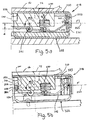
- a locking mechanism 18' has a hub assembly 20', a housing 22', an upper spring 24', a central adjustment spring 30' disposed beneath an adjustment plug 32', and a retaining device 34' which retains the hub assembly to the housing.
- the hub assembly 20' includes a hub 36' having pivot trunnions 38, a guard 40' and a linkage 42a' both of which attach to the hub and are rotatable therewith.
- the linkage 42a' is pivotally connected from a pivot trunnion 38' to a slider-pawl 42b'.
- the plug 32' is in threaded engagement with the hub 36'.
- the adjustment spring 30' is disposed between the housing 22' and the plug 32'.
- the plug 32' includes a torque transmitting interface 44' which permits a torque transmitting tool (not shown) to rotate the plug, thus varying the preload of the adjustment spring 32'.
- the housing 22' includes an insert 23.
- the insert is made of a durable polymeric material such as a fiber-reinforced phenolic. When worn, the insert 23 may be removed, discarded, and replaced.
- a friction generating annulus 46' is fixedly attached to an inner surface 50' of the guard 40'.
- the upper spring 24' is disposed between a surface 25 of the slider-pawl 42b' and a surface 27 of the hub 36'.
- the retaining device 34' retains the hub 36' in rotatable engagement with the housing 22' and prevents disassembly.
- the retaining device 34' is attached to the housing 22' via fasteners 37.
- the adjustment spring 30' biases the hub assembly 20' into an unlocked position with respect to the housing 22' in which a surface 64' of an outer lip 66' of the hub 36' rests against a surface 70' of the retaining device 34'.
- the hub assembly 20' attaches to the boot 16 via fasteners 72'.
- the housing 22' attaches to the board 12 via fasteners 74'.
- the locking mechanism 18' is responsive to a normal force N perated when the binding 14 supports at least a portion of the weight W of an operator.
- the weight W of the operator is opposed by the normal force N which compresses the adjustment spring 30' and moves the hub assembly 20' away from a fully unlocked position further into a cavity 31 of the housing 22' until the outer surface 62' of the slider-pawl 42b' bears against an inner surface 76' of the insert 23 and, consequently, against the housing 22'.
- the outer surface 62' of the slider-pawl 42b' may optionally be knurled or serrated in order to increase friction or create actual interference engagement with the inner surface 76' of the insert 23 when the locking mechanism 18' is in the locked position as shown.
- the locking mechanism 18' substantially restricts rotational motion of the binding 14 when actuated as shown and permits substantially free rotational motion of the binding when the locking mechanism is not actuated (as shown in Fig. 4a ).
- the guard 40' functions in the same males as in the previous embodiment.
- the binding when no weight is applied to the binding 14, the binding is substantially free to rotate about its axis during a jump of the operator.
- the binding 14 begins to resist rotational movement when the weight W of the operator is supported at least in part by the binding.
- an alternate locking mechanism 218 includes a overcenter mechanism.
- the locking mechanism 218 is configured such that a spring force F1 against an end 262 of the arm 242 has a line of action 263 which passes over a pivot point 241 a perpendicular distance d.
- the spring constant of the spring force F1 may optionally be selected such that a resultant downward force on a hub assembly 220 created by the moment M1 (defined by the distance d from the line of action 263 of the spring force to the pivot point 241, multiplied by the spring force) is greater than an upward force F2, created for example by compression spring 230, which tends to raise the hub assembly 220 to its uppermost position, thus keeping the locking mechanism locked unless a sufficient additional upward force is applied, by, for example, lifting up on one foot at a time, in which the other foot secures the board such that it does not move relative to the foot being lifted, thus separating the hub assembly 220 from the housing 222.
- the spring action creating the spring force F1 may be created by flexing of the arm 242, by flexing of a wall 221 of the housing 222, by flexing of an elastomeric lining 223, or a combination of these.
- a housing 322 of a locking mechanism 318 includes a slit 323 allowing the housing to expand when an arm 342 reacts against it, thus helping take up unwanted slack in the binding 14.
- a surface 421 of a housing 422 and a surface 435 of a hub 436 include annular serrations 423 and 437, respectively, which interlock when the locking mechanism 418 locks, thus further limiting the relative up and down motion of surfaces 423 and 437 with respect to each other when a bending moment (not shown) is applied to the locking mechanism 418, such as when stopping. This further locks the binding 14 against unwanted rocking.
- a single serration or lip on each surface 423 and 437 may of course be used instead of the four shown in the figure. In any case, one or the other, or both serrations should include chamfers 439 to prevent binding when the housing 422 and the hub assembly 436 separate.
- a bolt 250 and nut 252 prevent the hub assembly 320 from separating from the housing 322.
- the bolt 250 and nut 252 are in a recess 254 having a shoulder 256 at a lower end.
- the recess 254 and shoulder 256 are sized such that an inner diameter of the recess 256 is large enough to permit the nut 252 to pass through it.
- An annular insert 258 is displaced within the recess 254, between the shoulder 256 and the nut 252.
- the insert 258 may be a split elastic annulus having an aperture 262 through which a shaft of the bolt 250 passes or be otherwise formed such that its outer diameter 260 can contract when a sufficient contracting force is applied to the diameter.
- the contracting force is generated as the curved or chamfered surface 262 slides against the recess 254 in a ramp-like fashion, thus contracting the diameter 260 of the insert 258 such that it can pass over the shoulder 256 and permit separation of the operator from the board 12 when a sufficient separation force is applied.
- Such separation is desirable when the sports board 12 is a snowboard and the operator is caught in a avalanche.
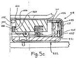
- an emergency release which comprises a insert 458 having a major external diameter 460 and a lip 456 or a larger diameter.
- the major external diameter 460 corresponds to the maximum diameter of the nut 252.
- the lip 456 is sized such that at a certain tensile force, it will shear off of the remainder of the insert 458, thus permitting the separation of the operator from the board 12 in an emergency as described above.
- the operator having each foot supported in a binding 14 attached to the board 12 of the sports board 10, moves one boot 16 forward a certain extent and the other backward a certain extent and then, optionally, reverses direction of motion thus simulating a walking-like motion, during the jump itself.
- a secondary locking mechanism 90 selectively prevents rotational motion whether or not the binding 14 supports at least a portion of the weight W of the operator.
- the secondary locking mechanism 90 includes a pawl 92 pivotally attached via a pin 93 to a trunnion member 94 and a toggle linkage 95 which pivotally attaches to the pawl via a pin 96.
- the toggle linkage 95 has a spring biasing means 97 (such as a eyelet and spring detent) disposed therein The operator may rotate the toggle linkage 95 between a first locking position 100, shown in Fig.
- a boss 102 of the pawl 92 is biased to enter a recess or hole 104, one of a number of holes radially evenly spaced about the circumferential surface 105 of the guard 40 or 40' (Fig. 4b shows the boss as it is about to enter the hole 104 and lock the binding), and a second free position 106, shown in Fig. 4a , in which the boss 102 is biased away from the hole, permitting the binding 14 to operate as described above.
- at least two secondary locking mechanisms 90 should be provided per binding 14 at opposite sides of the binding.
- An advantage of the invention is that it permits the operator (a) to perform a walking-like motion during a jump, (b) to reposition his feet during a sports board run such as when making a turn.
- the binding 14 further provides substantially rigid torsionally-resistant support when a predetermined amount of the operator's weight is supported by the binding.
- Still another advantage of the invention is that the binding 14 absorbs a significant amount of shock, thus helping protect the operator's legs from injury or fatigue.
- Still another advantage is that the operator, after sports boarding down a slope, can release his rear boot 16 from the binding 15 and reposition his front foot to his preferred orientation for pushing along with his free foot to move the sports board.
- Still another advantage is the operator is free to reposition his feet when dismounting a ski lift. Further, when the operator rides the lift, his feet are free to take a comfortable position due the fact that the bindings 14 freely rotate when no weight is placed on them by the operator.
Landscapes
- Footwear And Its Accessory, Manufacturing Method And Apparatuses (AREA)
- Clamps And Clips (AREA)
Applications Claiming Priority (2)
| Application Number | Priority Date | Filing Date | Title |
|---|---|---|---|
| US7807998P | 1998-03-13 | 1998-03-13 | |
| US78079P | 1998-03-13 |
Publications (2)
| Publication Number | Publication Date |
|---|---|
| EP0941752A2 true EP0941752A2 (fr) | 1999-09-15 |
| EP0941752A3 EP0941752A3 (fr) | 1999-11-03 |
Family
ID=22141792
Family Applications (1)
| Application Number | Title | Priority Date | Filing Date |
|---|---|---|---|
| EP99104809A Withdrawn EP0941752A3 (fr) | 1998-03-13 | 1999-03-09 | Planche de sport avec une fixation utilisant un bloquage sensible au poids |
Country Status (2)
| Country | Link |
|---|---|
| EP (1) | EP0941752A3 (fr) |
| CA (1) | CA2265332A1 (fr) |
Cited By (1)
| Publication number | Priority date | Publication date | Assignee | Title |
|---|---|---|---|---|
| WO2013177697A1 (fr) * | 2012-05-29 | 2013-12-05 | Ocean Rodeo Sports Inc. | Planche de déplacement adaptable |
Citations (1)
| Publication number | Priority date | Publication date | Assignee | Title |
|---|---|---|---|---|
| US4964649A (en) | 1989-03-15 | 1990-10-23 | Chamberlin Justin M | Snowboard boot binder attachments |
Family Cites Families (3)
| Publication number | Priority date | Publication date | Assignee | Title |
|---|---|---|---|---|
| CH672432A5 (fr) * | 1987-03-27 | 1989-11-30 | Hansruedi Naepflin | |
| FR2650752A1 (fr) * | 1989-08-11 | 1991-02-15 | Boineau Christian | Dispositif pour pratiquer un sport de glisse sur la neige |
| FR2656227A1 (fr) * | 1989-12-22 | 1991-06-28 | Gabri Gilles | Fixation a plaque tournante pour surf des neiges. |
-
1999
- 1999-03-09 EP EP99104809A patent/EP0941752A3/fr not_active Withdrawn
- 1999-03-12 CA CA 2265332 patent/CA2265332A1/fr not_active Abandoned
Patent Citations (1)
| Publication number | Priority date | Publication date | Assignee | Title |
|---|---|---|---|---|
| US4964649A (en) | 1989-03-15 | 1990-10-23 | Chamberlin Justin M | Snowboard boot binder attachments |
Cited By (1)
| Publication number | Priority date | Publication date | Assignee | Title |
|---|---|---|---|---|
| WO2013177697A1 (fr) * | 2012-05-29 | 2013-12-05 | Ocean Rodeo Sports Inc. | Planche de déplacement adaptable |
Also Published As
| Publication number | Publication date |
|---|---|
| EP0941752A3 (fr) | 1999-11-03 |
| CA2265332A1 (fr) | 1999-09-13 |
Similar Documents
| Publication | Publication Date | Title |
|---|---|---|
| US5044654A (en) | Plate release binding winter sports device | |
| US5699699A (en) | Connecting structure between bicycle pedal and cleat, bicycle pedal and cleat | |
| EP1741474B1 (fr) | Fixation de snowboard comprenant un système de connection rotatif avec moyen de friction | |
| US5852852A (en) | Tightening device with serrated strap and ratchet locking member | |
| US4803894A (en) | Bicycle pedalling apparatus | |
| US6099018A (en) | Snowboard binding | |
| EP0815905A2 (fr) | Réglage angulaire, notamment pour fixation d'une planche à neige | |
| JP2010538756A (ja) | 多機能ビンディングシステム | |
| US6739615B1 (en) | Snowboard binding | |
| WO1998024522A2 (fr) | Ensemble fixation rotatif et reglable destine a une planche a neige | |
| US7290785B2 (en) | Angular adjustment mechanism for snowboard bindings | |
| EP0155114A2 (fr) | Pédalier de bicyclette | |
| US6966563B2 (en) | Safety device for snowboards | |
| EP0941752A2 (fr) | Planche de sport avec une fixation utilisant un bloquage sensible au poids | |
| JP2007504865A (ja) | スノーボード制動機 | |
| JP2009022769A (ja) | 万能締め具装置 | |
| US6698169B1 (en) | Safety stirrup | |
| EP1249259A2 (fr) | Fixation pour planche à neige | |
| EP1093338A1 (fr) | Boucle double action | |
| WO2012177783A2 (fr) | Fixations de planche à neige améliorées | |
| US20240083554A1 (en) | Binding | |
| RU2648199C1 (ru) | Замок для крепления спортивного снаряда, сбрасываемого при падении (варианты) | |
| US20060108772A1 (en) | Rotation adapter assembly for a snowboard binder | |
| EP2455141A1 (fr) | Ensemble de fixation de planche à neige | |
| AU772383B2 (en) | Safety stirrup |
Legal Events
| Date | Code | Title | Description |
|---|---|---|---|
| PUAI | Public reference made under article 153(3) epc to a published international application that has entered the european phase |
Free format text: ORIGINAL CODE: 0009012 |
|
| AK | Designated contracting states |
Kind code of ref document: A2 Designated state(s): AT BE CH CY DE DK ES FI FR GB GR IE IT LI LU MC NL PT SE |
|
| AX | Request for extension of the european patent |
Free format text: AL;LT;LV;MK;RO;SI |
|
| PUAL | Search report despatched |
Free format text: ORIGINAL CODE: 0009013 |
|
| AK | Designated contracting states |
Kind code of ref document: A3 Designated state(s): AT BE CH CY DE DK ES FI FR GB GR IE IT LI LU MC NL PT SE |
|
| AX | Request for extension of the european patent |
Free format text: AL;LT;LV;MK;RO;SI |
|
| AKX | Designation fees paid | ||
| REG | Reference to a national code |
Ref country code: DE Ref legal event code: 8566 |
|
| STAA | Information on the status of an ep patent application or granted ep patent |
Free format text: STATUS: THE APPLICATION IS DEEMED TO BE WITHDRAWN |
|
| 18D | Application deemed to be withdrawn |
Effective date: 20000504 |