US10480571B2 - Self locking bearing preload adjuster - Google Patents
Self locking bearing preload adjuster Download PDFInfo
- Publication number
- US10480571B2 US10480571B2 US16/250,593 US201916250593A US10480571B2 US 10480571 B2 US10480571 B2 US 10480571B2 US 201916250593 A US201916250593 A US 201916250593A US 10480571 B2 US10480571 B2 US 10480571B2
- Authority
- US
- United States
- Prior art keywords
- bottom bracket
- bearing
- crank
- adjuster
- adjustment ring
- Prior art date
- Legal status (The legal status is an assumption and is not a legal conclusion. Google has not performed a legal analysis and makes no representation as to the accuracy of the status listed.)
- Active
Links
Images


Classifications
-
- F—MECHANICAL ENGINEERING; LIGHTING; HEATING; WEAPONS; BLASTING
- F16—ENGINEERING ELEMENTS AND UNITS; GENERAL MEASURES FOR PRODUCING AND MAINTAINING EFFECTIVE FUNCTIONING OF MACHINES OR INSTALLATIONS; THERMAL INSULATION IN GENERAL
- F16C—SHAFTS; FLEXIBLE SHAFTS; ELEMENTS OR CRANKSHAFT MECHANISMS; ROTARY BODIES OTHER THAN GEARING ELEMENTS; BEARINGS
- F16C25/00—Bearings for exclusively rotary movement adjustable for wear or play
- F16C25/06—Ball or roller bearings
-
- B—PERFORMING OPERATIONS; TRANSPORTING
- B62—LAND VEHICLES FOR TRAVELLING OTHERWISE THAN ON RAILS
- B62M—RIDER PROPULSION OF WHEELED VEHICLES OR SLEDGES; POWERED PROPULSION OF SLEDGES OR SINGLE-TRACK CYCLES; TRANSMISSIONS SPECIALLY ADAPTED FOR SUCH VEHICLES
- B62M3/00—Construction of cranks operated by hand or foot
- B62M3/003—Combination of crank axles and bearings housed in the bottom bracket
-
- F—MECHANICAL ENGINEERING; LIGHTING; HEATING; WEAPONS; BLASTING
- F16—ENGINEERING ELEMENTS AND UNITS; GENERAL MEASURES FOR PRODUCING AND MAINTAINING EFFECTIVE FUNCTIONING OF MACHINES OR INSTALLATIONS; THERMAL INSULATION IN GENERAL
- F16C—SHAFTS; FLEXIBLE SHAFTS; ELEMENTS OR CRANKSHAFT MECHANISMS; ROTARY BODIES OTHER THAN GEARING ELEMENTS; BEARINGS
- F16C2326/00—Articles relating to transporting
- F16C2326/20—Land vehicles
- F16C2326/28—Bicycle propulsion, e.g. crankshaft and its support
-
- Y—GENERAL TAGGING OF NEW TECHNOLOGICAL DEVELOPMENTS; GENERAL TAGGING OF CROSS-SECTIONAL TECHNOLOGIES SPANNING OVER SEVERAL SECTIONS OF THE IPC; TECHNICAL SUBJECTS COVERED BY FORMER USPC CROSS-REFERENCE ART COLLECTIONS [XRACs] AND DIGESTS
- Y10—TECHNICAL SUBJECTS COVERED BY FORMER USPC
- Y10T—TECHNICAL SUBJECTS COVERED BY FORMER US CLASSIFICATION
- Y10T29/00—Metal working
- Y10T29/49—Method of mechanical manufacture
- Y10T29/49636—Process for making bearing or component thereof
- Y10T29/49696—Mounting
-
- Y—GENERAL TAGGING OF NEW TECHNOLOGICAL DEVELOPMENTS; GENERAL TAGGING OF CROSS-SECTIONAL TECHNOLOGIES SPANNING OVER SEVERAL SECTIONS OF THE IPC; TECHNICAL SUBJECTS COVERED BY FORMER USPC CROSS-REFERENCE ART COLLECTIONS [XRACs] AND DIGESTS
- Y10—TECHNICAL SUBJECTS COVERED BY FORMER USPC
- Y10T—TECHNICAL SUBJECTS COVERED BY FORMER US CLASSIFICATION
- Y10T74/00—Machine element or mechanism
- Y10T74/21—Elements
- Y10T74/2164—Cranks and pedals
- Y10T74/2165—Cranks and pedals with attached gear
Definitions
- the present invention is generally directed to the field of bicycles and bicycle components. More specifically, the present invention is directed to a method and system for adjusting the bearing preload in a bicycle bottom bracket assembly.
- the ball bearings of the bottom bracket assembly must be preloaded in order for the crank set to properly function.
- Preloading the bearings eliminates lateral movement of the crankset and applies a pressure to the bearings of the bottom bracket so that the bearings only move in a wanted direction and do not give in the radial or axial direction.
- Optimal preloading of the bearings eliminates side-to-side play of the crankset, which may result in a dropped chain, and also prevents the bearings from being too heavily loaded, which decreases the life of the bearings and may cause the crank to seize.
- crank set and bottom bracket assembly is often found as an integrated system including complementary sized components to adapt to the bicycle frame.
- spacers such as elastomer washers or caps which are able to be tightened may be used in order to eliminate play in the crank arms and achieve a proper bearing preload. In either case, properly adjusting the preload of the bottom bracket bearings requires a variety of tools and may require readjustment as the bearings are broken in and play develops within the crank arms and the bottom bracket assembly.
- a system and method eliminates play and adjusts the preload of ball bearings, where two or more bearings are used to support the spindle of a bicycle crank set and in other similar bearing-spindle arrangements.
- a self locking preload adjuster allows for the simple application of bearing preload in order to eliminate the free play of a bearing system without requiring the use of any tools.
- a bearing preload adjuster for a bicycle crank set and bottom bracket comprises an adjustment ring for coupling with a bicycle crank arm, a movable plunger comprising an external thread for rotatably coupling with the adjustment ring, and a detent spring.
- the bearing preload adjuster is configured to couple with a non-drive side crank arm of the bicycle.
- the bearing preload adjuster comprises one or more anti-rotation features that are configured to couple with the non-drive side crank arm of the bicycle.
- the adjustment ring is rotated in order to move the plunger and apply preload to one or more bearings of the bottom bracket.
- the detent spring prevents the movable plunger from backing out once it has been moved in order to apply preload to the one or more bearings of the bottom bracket.
- the adjustment ring is only rotatable in a counter-clockwise direction.
- the bearing preload adjuster comprises a triple-start thread which is used to apply preload to the bearings.
- the bearing preload adjuster comprises a gasket adapted to prevent water and dirt from contacting the one or more bearings of the bottom bracket.
- a crank set for a bicycle comprises a drive side crank arm comprising one or more chain rings, a non-drive side crank arm, and an extendable bearing preload adjuster coupled between the non-drive side crank arm and a bottom bracket assembly of the bicycle.
- the bearing preload adjuster comprises one or more anti-rotation features that are configured to couple with the non-drive side crank arm of the bicycle.
- the bearing preload adjuster is rotated in order to extend a plunger and apply preload to one or more bearings of the bottom bracket.
- a detent spring prevents the plunger from backing out once it has been moved in order to apply preload to the one or more bearings of the bottom bracket.
- the bearing preload adjuster is only rotatable in a counter-clockwise direction. In some embodiments, the bearing preload adjuster comprises a triple-start thread which is used to apply preload to the bearings. In some embodiments, the bearing preload adjuster further comprises a gasket adapted to prevent water and dirt from contacting the one or more bearings of the bottom bracket.
- a method of preloading one or more bearings of a bicycle bottom bracket comprises coupling a drive-side crank arm and crank spindle with the bicycle, coupling a bearing preload adjuster with a non-drive side crank arm of a bicycle, coupling the non-drive side crank arm with the bicycle, and rotating the bearing preload adjuster in order to extend a plunger along an axis of the crank spindle so that the plunger contacts an inner race of a left bearing and applies a preload force between the left bearing and a right bearing of the bottom bracket.
- the bearing preload adjuster is only rotatable in a counter-clockwise direction.
- the bearing preload adjuster is locked in place after preload has been applied to the bearings. In some embodiments, the bearing preload adjuster is rotated by hand. In some embodiments, the bearing preload adjuster comprises one or more anti-rotation features that are configured to couple with the non-drive side crank arm of the bicycle
- FIG. 1 illustrates an angled view of a crank set assembled to a bicycle frame in accordance with some embodiments.
- FIG. 2 illustrates a top view of a crank set assembled to a bicycle frame in accordance with some embodiments.
- FIG. 3 illustrates a right side view of a crank set assembled to a bicycle frame in accordance with some embodiments.
- FIG. 4 illustrates a crank set with a preload adjuster installed on a bicycle in accordance with some embodiments.
- FIG. 5 illustrates a crank set with a preload adjuster section in an open position in accordance with some embodiments.
- FIG. 6 illustrates a crank set with a preload adjuster section in a closed position in accordance with some embodiments.
- FIG. 7 illustrates an exploded view of a preload adjuster in accordance with some embodiments.
- FIG. 8 illustrates an exploded view of a preload adjuster in accordance with some embodiments.
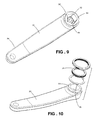
- FIG. 9 illustrates a left crank arm without a preload adjuster in accordance with some embodiments.
- FIG. 10 illustrates a left crank arm with an exploded view of a preload adjuster in accordance with some embodiments.
- FIG. 11 illustrates a method of preloading one or more bearings of a bicycle bottom bracket in accordance with some embodiments.
- Embodiments of the invention are directed to a system and method for eliminating play and adjusting the preload of ball bearings, where two or more bearings are used to support the spindle of a bicycle crank set and in other similar bearing-spindle arrangements.
- a self locking preload adjuster allows for the simple application of bearing preload in order to eliminate the free play of a bearing system without requiring the use of any tools.
- a bicycle crank set and bottom bracket assembly 10 is shown installed on a bicycle frame bottom bracket assembly 12 .
- the crank set and bottom bracket assembly 10 is shown as cut away from the complete bicycle frame.
- the bicycle frame bottom bracket assembly 12 comprises a bottom bracket shell 14 , which is composed of a left end 16 and a right end 18 .
- the crank set and bottom bracket assembly 10 includes a left crank arm 20 , a right crank arm 22 , and one or more chain rings 24 .
- the left crank arm 20 comprises the non-drive side crank arm and the right side crank arm 22 with the one or more chain rings 24 comprising the drive side crank arm.
- the crank set and bottom bracket assembly 10 also includes a left bottom bracket cup assembly 26 , a right bottom bracket cup assembly 28 , and a preload adjuster assembly 30 .
- the bottom bracket cup assemblies include a left bottom bracket cup 32 and a right bottom bracket cup 34 , a left bottom bracket ball bearing 36 and a right bottom bracket ball bearing 38 .
- the left bottom bracket ball bearing 36 comprises a left inner race 40 , a left outer race 42 and a plurality of balls 44 between the left inner race 40 and the left outer race 42 .
- the right bottom bracket ball bearing 38 comprises a right inner race 46 , a right outer race 48 and a plurality of balls 50 between the right inner race 46 and the right outer race 48 .
- the bicycle crank set and bottom bracket assembly 10 includes a crank spindle 52 , which is rigidly attached to the right arm 22 , and a crank fastening bolt 54 which rigidly couples the left crank arm 20 to the crank spindle 52 .
- crank spindle 52 is supported radially by the left inner race 40 and the right inner race 46 .
- the right crank arm 22 contacts the right inner race 46 on its right-most surface.
- a preload adjuster assembly 30 comprises an adjustment ring 56 , a plunger 58 and a detent spring 60 .
- the adjustment ring 56 comprises a threaded hole 62 , an internal right-hand triple-start thread 63 , one or more adjustment ring detent features 64 , and an adjustment grip feature 66 on the exterior surface 68 of the adjustment ring 56 .
- the plunger 58 comprises an external right-hand triple start thread 70 , sized to engage the internal right-hand triple start thread 63 of the threaded hole 62 .
- the plunger end 72 comprises a pocket 74 , which contains one or more plunger anti-rotation features 76 .
- a spindle clearance hole 78 passes entirely through the center of the plunger 58 to allow the crank spindle 52 to pass through the plunger 58 .
- the detent spring 60 includes an outer surface 80 , a through hole 82 , and one or more spring anti-rotation features 84 , shaped to match the plunger 58 anti-rotation features 76 .
- the detent spring 60 also comprises one or more detent engagement features 86 , sized to engage the adjustment ring 56 detent features 64 .
- the detent spring 60 only includes one detent engagement feature 86 , it is contemplated that the detent spring 60 is able to include any number of detent features as appropriately desired.
- the adjustment ring 56 is able to comprise any number of detent features 64 as appropriately desired.
- the one or more detent features 64 are able to be located on an exterior surface of the adjustment ring 54 .
- the detent features 64 are located on a face surrounding a root of an adjuster boss 94 ( FIG. 9 ) and part of the left crank arm 20 , and the detent engagement feature 86 is a component of the adjustment ring 56 thereby eliminating the need for the detent spring 60 .
- the detent spring 60 is able to comprise a feature of the crank arm such as a ball-and-spring assembly or spring-and-plunger in order to provide the locking feature of the detent spring 60 .
- the preload adjuster assembly 30 comprises a gasket 100 for preventing water, dirt and debris from contacting the bearings of the bottom bracket when the preload adjuster assembly is coupled to the bottom bracket.
- the gasket 100 comprises a rubber gasket.
- the gasket 100 is a component of the detent spring 60 .
- FIG. 8 illustrates the preload adjuster assembly 30 in an assembled configuration.
- the plunger pocket 74 is fitted over the adjuster boss 94 , such that the one or more crank anti-rotation features 96 engage with the one or more plunger 58 anti-rotation features 76 and the one or more detent spring 60 anti-rotation features 84 .
- the anti-rotation features of the plunger 58 , the detent spring 60 and the adjuster boss 94 are able to take the form of a circular shape with a flat portion, a key and key way shape, or a splined inner shape in the plunger 58 and detent spring 60 , or any other appropriate anti-rotation feature as known in the art.
- the left crank arm 20 and the right crank arm 22 are fixed to the crank spindle 52 , so that once installed, the crank arms and the spindle 52 rotate as one unit on the left and the right bottom bracket bearings.
- the preload adjuster 30 eliminates play in the bearings, allowing the crank assembly to rotate without the bearings sliding side to side.
- the left bottom bracket cup 32 and the right bottom bracket cup 34 are installed on the bicycle frame.
- the bottom bracket cups are press fit or threaded into the frame.
- the bearings may be fitted directly into the frame using appropriately sized pockets in the bottom bracket assembly 12 .
- crank spindle 52 is permanently attached to the right crank arm 22 .
- the spindle 52 is passed through the bottom bracket bearings so that the left crank arm interface 92 is able to attach to the spindle left end 91 and the right crank arm 22 presses against the right inner race 46 of the right bottom bracket ball bearing 38 .
- the preload adjuster 30 is slid over the adjuster boss 94 of the left crank arm 20 so that the one or more anti-rotation features of the preload adjuster 30 engage with the one or more crank anti-rotation features 96 . Then, the left crank arm 20 is attached to the crank spindle 52 by tightening the crank fastening bolt 54 . In this position, the preload adjuster assembly 30 is attached to the left crank arm 20 , and the left crank arm 20 is attached to the crank spindle 52 by the crank fastening bolt 54 . On initial installation, a small gap is present between the plunger 58 and the left inner race 40 of the left bottom bracket bearing 36 . The small gap allows for tolerance variations between frames and variations in the dimensions of different bicycle frames and enabling the crank set to be used on a variety of different bicycles.
- the adjustment ring 56 is rotated to further apply a pre-load force between the left bottom bracket ball bearing 36 and the right bottom bracket ball bearing 38 .
- the threaded interface between the adjustment ring 56 and the plunger 58 causes the plunger 58 to extend along the long axis of the spindle 52 , away from the left crank arm, so that the plunger 58 contacts the left bearing inner race 42 .
- the adjustment ring 56 is rotated until the clearance in the bearing assemblies and the play in the bottom bracket assembly has been eliminated. This allows the crank assembly to rotate freely, while preventing the crank assembly from sliding side to side inside the bearing bores and along the axis of the crank spindle 52 .
- the adjustment ring 56 is rotated in a counter-clockwise direction as viewed from an outside edge of the left crank arm 20 in order to extend the plunger 58 to contact the left bearing inner race 42 .
- the thread between the adjustment ring 56 and the plunger 58 is a right-hand triple start thread.
- a right-hand thread prevents the adjustment ring 56 from being inadvertently rotated by a processing movement between the left crank arm 20 and the left inner race 40 . Precession may occur as a pedaling load is applied to the left crank arm 20 and the crank spindle 52 and the spindle interface flexes. As the left crank arm rotates through 360 degrees, the force between the plunger 58 and the inner race 40 may be un-evenly applied between the two surfaces, which could cause the adjustment ring 56 to rotate if a left-hand thread is used.
- the detent feature 86 of the detent spring 60 engages with a detent feature 64 of the adjustment ring 56 so that the preload force on the end of the plunger 58 does not cause the adjustment ring 56 to reverse rotation and relieve the preload force under operation.
- the detent feature 86 of the detent spring 60 engages with a detent feature 64 of the adjustment ring 56 in order to lock the plunger in an extended position in order to provide a consistent preload force.
- the preload adjuster assembly 30 has been installed in the un-loaded position. As described above, and as shown in FIG. 5 , on initial installation of the preload adjuster assembly 30 , a bearing gap 98 is present between the plunger 58 and the inner bearing race 40 of the left bottom bracket bearing 36 . As described above, in some embodiments, the adjustment ring 56 is rotated in a counter-clockwise direction, as indicated by the arrow until the clearance in the bearing assemblies and the play in the bottom bracket assembly has been eliminated.
- FIG. 6 shows the preload adjuster 30 in a closed, pre-loaded position.
- the bearing gap 98 has been eliminated by an extension of the plunger 58 , and the bearing play in the left bottom bracket bearing 36 and the right bottom bracket bearing 38 has been removed.
- FIG. 11 shows a method of preloading one or more bearings of a bicycle bottom bracket in accordance with some embodiments.
- the method begins in the step 1110 .
- a drive-side crank arm and crank spindle are coupled with the bicycle frame.
- the crank spindle is passed through the bottom bracket bearings of the bicycle and the drive-side crank arm presses against an inner race of a bottom bracket ball bearing.
- a bearing preload adjuster is coupled with a non-drive side crank arm of the bicycle.
- the preload adjuster is slid onto the crank arm so that one or more anti-rotation features of the preload adjuster engage with one or more crank anti-rotation features of the non-drive side crank arm.
- the non-drive side crank arm is coupled with the bicycle.
- the bearing preload adjuster is rotated in order to extend a plunger along an axis of the crank spindle until the plunger contacts an inner race of the bottom bracket bearings of the bicycle.
- the preload adjuster applies a force between the bearings of the bottom bracket in order to eliminate side-to-side movements of the bearings and eliminate play in the bottom bracket assembly.
- a thread of the preload adjuster is a right-hand triple start thread. Consequently, the bearing preload adjuster is only rotatable in a counter-clockwise direction. In some embodiments, the bearing preload adjuster is locked in place after preload has been applied to the bearings. In some embodiments, the bearing preload adjuster is rotated by hand. Additionally, as described above, in some embodiments, the bearing preload adjuster comprises one or more detent features that are configured to couple with the non-drive side crank arm of the bicycle
- the bearing pre-load adjuster 30 allows a user to easily adjust the preload of ball bearings used to support the spindle of the bicycle crank set.
- the user is able to couple the pre-load adjuster 30 with the crank set and rotate the adjuster in order to apply preload to the bearings and take the free play out of the system without the use of tools.
- assembly is simplified for the end user.
- Bearing preload is able to be set using only fingers to adjust the preload mechanism. Additionally, because the adjuster is self-locking, once proper bearing preload is achieved, the preload will not change during operation of the bicycle.
- the bearing pre-load adjuster 30 uses a triple-start thread to apply preload to the bearings, the amount of preload force which can be applied using ones fingers is decreased. Consequently, the bearings will not be overloaded by over-tightening of the preload adjuster. Additionally, the detent feature of the detent spring engages with the detent feature of the adjustment ring and ensures that the preload force on the end of the plunger does not cause the adjustment ring to reverse rotation and relieve the preload force under operation. Accordingly, the presently claimed invention as described herein has many advantages.
Abstract
Description
Claims (4)
Priority Applications (1)
| Application Number | Priority Date | Filing Date | Title |
|---|---|---|---|
| US16/250,593 US10480571B2 (en) | 2012-12-06 | 2019-01-17 | Self locking bearing preload adjuster |
Applications Claiming Priority (3)
| Application Number | Priority Date | Filing Date | Title |
|---|---|---|---|
| US201261734065P | 2012-12-06 | 2012-12-06 | |
| US14/099,641 US10221887B2 (en) | 2012-12-06 | 2013-12-06 | Self locking bearing preload adjuster |
| US16/250,593 US10480571B2 (en) | 2012-12-06 | 2019-01-17 | Self locking bearing preload adjuster |
Related Parent Applications (1)
| Application Number | Title | Priority Date | Filing Date |
|---|---|---|---|
| US14/099,641 Division US10221887B2 (en) | 2012-12-06 | 2013-12-06 | Self locking bearing preload adjuster |
Publications (2)
| Publication Number | Publication Date |
|---|---|
| US20190154083A1 US20190154083A1 (en) | 2019-05-23 |
| US10480571B2 true US10480571B2 (en) | 2019-11-19 |
Family
ID=50879554
Family Applications (2)
| Application Number | Title | Priority Date | Filing Date |
|---|---|---|---|
| US14/099,641 Active 2035-06-25 US10221887B2 (en) | 2012-12-06 | 2013-12-06 | Self locking bearing preload adjuster |
| US16/250,593 Active US10480571B2 (en) | 2012-12-06 | 2019-01-17 | Self locking bearing preload adjuster |
Family Applications Before (1)
| Application Number | Title | Priority Date | Filing Date |
|---|---|---|---|
| US14/099,641 Active 2035-06-25 US10221887B2 (en) | 2012-12-06 | 2013-12-06 | Self locking bearing preload adjuster |
Country Status (1)
| Country | Link |
|---|---|
| US (2) | US10221887B2 (en) |
Cited By (3)
| Publication number | Priority date | Publication date | Assignee | Title |
|---|---|---|---|---|
| US11351815B2 (en) | 2017-08-21 | 2022-06-07 | The Hive Global, Inc. | Bicycle cassette with clamping connection |
| US11485449B2 (en) | 2015-09-01 | 2022-11-01 | The Hive Global, Inc. | Bicycle cassette with locking connection |
| US11932351B2 (en) | 2020-07-17 | 2024-03-19 | The Hive Global, Inc. | Conical bicycle cassette sprocket structure |
Families Citing this family (9)
| Publication number | Priority date | Publication date | Assignee | Title |
|---|---|---|---|---|
| US8820192B2 (en) | 2009-04-29 | 2014-09-02 | Race Face Prerformance Products Inc. | Bicycle crank arm and insert therefore |
| US10221887B2 (en) | 2012-12-06 | 2019-03-05 | The Hive Global, Inc | Self locking bearing preload adjuster |
| CN112517887A (en) | 2016-04-11 | 2021-03-19 | 福克斯制造有限公司 | Method for forming a bicycle front sprocket assembly |
| US10300974B1 (en) | 2017-02-03 | 2019-05-28 | O'Reilly Enterprises, Inc | Balance bike conversion systems |
| US11014628B2 (en) * | 2017-04-28 | 2021-05-25 | Fox Factory, Inc. | Cinch direct mount 2X ring system |
| ES2725324B2 (en) * | 2018-03-23 | 2020-01-27 | Bikone Bearings S L | DEVICE FOR PRECAUTION OF THE PEDALIER OF A BICYCLE |
| US11359709B2 (en) | 2018-12-18 | 2022-06-14 | Fox Factory, Inc. | Chainring |
| US11680633B2 (en) * | 2019-02-08 | 2023-06-20 | Fox Factory, Inc. | Chainring |
| US11814135B2 (en) * | 2022-04-14 | 2023-11-14 | Shimano Inc. | Crank assembly for human powered vehicle |
Citations (236)
| Publication number | Priority date | Publication date | Assignee | Title |
|---|---|---|---|---|
| US512729A (en) | 1894-01-16 | Harry lucas and james archer | ||
| US527384A (en) | 1894-10-09 | Bicycle-pedal | ||
| US527520A (en) | 1894-10-16 | copeland | ||
| US547639A (en) | 1895-10-08 | Bicycle-pedal | ||
| US575712A (en) | 1897-01-26 | Richard f | ||
| US576548A (en) | 1897-02-09 | Bicycle-pedal | ||
| US579479A (en) | 1897-03-23 | E morris petehs co | ||
| US590685A (en) | 1897-09-28 | Half to agnes jardine | ||
| US595388A (en) | 1897-12-14 | Bicycle-pedal attachment | ||
| US598325A (en) | 1898-02-01 | Gomeey mcintyre | ||
| US614900A (en) | 1898-11-29 | Velocipede-pedal | ||
| US616167A (en) | 1898-12-20 | James ernest a | ||
| US620266A (en) | 1899-02-28 | Julius wodiska | ||
| US666679A (en) | 1897-10-07 | 1901-01-29 | Stearns Bicycle Agency | Velocipede-pedal. |
| US1070971A (en) | 1912-07-17 | 1913-08-19 | Robert Todd Lowd | Pedal. |
| US1325206A (en) | 1919-12-16 | Driving-gear casing eor bicycles | ||
| US1400131A (en) | 1921-02-05 | 1921-12-13 | Howard A Jones | Sprocket-guard attachment for bicycles |
| US1535601A (en) | 1924-06-09 | 1925-04-28 | James H Graham | Pedal for bicycles |
| US1636327A (en) | 1926-05-12 | 1927-07-19 | Colson Company | Cycle |
| US2015430A (en) | 1935-03-02 | 1935-09-24 | Int Motor Co | Involute spline shaft |
| US2024499A (en) | 1933-04-13 | 1935-12-17 | Baron Johannes | Bicycle pedal |
| US2228770A (en) | 1938-08-19 | 1941-01-14 | Letourneau Inc | Shaft and hub mounting |
| US2317070A (en) | 1941-12-23 | 1943-04-20 | Letourneau Inc | Shaft and hub connection |
| US2567785A (en) | 1948-01-09 | 1951-09-11 | Rieger Mfg Company | Pedal for bicycles or the like |
| US2568443A (en) | 1948-09-22 | 1951-09-18 | Gerner Willi | Bicycle pedal |
| US2751797A (en) | 1952-06-18 | 1956-06-26 | Darwin Products Inc | Built-up pedal construction |
| US3185439A (en) | 1962-08-01 | 1965-05-25 | Fujitsu Ltd | Hydraulic motor control system |
| US3184993A (en) | 1963-12-11 | 1965-05-25 | Carl A Swenson | Derailleur guard |
| US3303720A (en) | 1963-11-20 | 1967-02-14 | Motobecane Ateliers | Folding pedal for bicycles and the like |
| US3382734A (en) | 1966-09-16 | 1968-05-14 | Ashtabula Bow Socket Company | Bicycle pedal |
| US3416385A (en) | 1967-03-20 | 1968-12-17 | Case Co J I | Sprocket assembly |
| US3477303A (en) | 1967-11-28 | 1969-11-11 | Schwinn Bicycle Co | Double plateau sprocket assembly |
| US3485113A (en) | 1966-07-19 | 1969-12-23 | Raleigh Industries Ltd | Pedals |
| US3592076A (en) | 1969-06-03 | 1971-07-13 | Ashtabula Bow Socket Co | Plastic bicycle pedal with a foot strap means |
| US3760653A (en) | 1971-03-12 | 1973-09-25 | Union Sils Van De Loo & Co | Pedal for bicycles |
| US3785129A (en) | 1971-11-01 | 1974-01-15 | Purolator Inc | Spin-on air filter |
| US3807255A (en) | 1969-06-03 | 1974-04-30 | Ashtabula Bow Socket Co | Plastic bicycle pedal |
| US3811339A (en) | 1972-08-17 | 1974-05-21 | Union Sils Van De Loo & Co | Pedal for bicycles and similar vehicles |
| US3869138A (en) | 1973-04-04 | 1975-03-04 | Ford Motor Co | Steering device having a chain operated steering gear actuator |
| US3910136A (en) | 1973-04-16 | 1975-10-07 | Lucien Charles Hippolyte Juy | Protection apparatus for a speed change mechanism of a bicycle or similar vehicle |
| US3964343A (en) | 1975-06-09 | 1976-06-22 | Lauterbach James H | Combination means for rigidly attaching shoe to a pedal for a foot-driven crank-operated machine |
| US3973447A (en) | 1974-06-06 | 1976-08-10 | Shimano Industrial Company, Limited | Derailleur for a bicycle |
| US4016357A (en) | 1975-07-18 | 1977-04-05 | Burroughs Corporation | Floor structure for the environment of a modular computer system |
| US4044621A (en) | 1975-06-09 | 1977-08-30 | Mcgregor Sr John C | Sprocket structure and chain guard |
| US4078444A (en) | 1976-02-13 | 1978-03-14 | Jacques Andre Huret | Front derailleur chain guide |
| US4089236A (en) | 1975-05-13 | 1978-05-16 | Claude Genzling | Safety connection between bicycle pedal and shoe |
| US4093325A (en) | 1975-10-30 | 1978-06-06 | Societe Nouvelle De Roulements | Tubular spindle mounting for bicycle bottom-bracket hub |
| US4135727A (en) | 1976-07-06 | 1979-01-23 | Tullio Campagnolo | Mounting of the transmission chain of bicycles |
| US4237743A (en) | 1977-10-11 | 1980-12-09 | Shimano Industrial Company, Limited | Front derailleur for a bicycle |
| US4240303A (en) | 1978-09-27 | 1980-12-23 | Mosley Earnest D | Chain sprocket with opposite frangible side guide plates |
| US4269084A (en) | 1978-08-11 | 1981-05-26 | Shimano Industrial Company, Limited | Toe clip for a bicycle pedal |
| US4298210A (en) | 1979-02-21 | 1981-11-03 | Jacques Lotteau | Device allowing a safety connection between the pedal of a bicycle and the shoe worn by the cyclist |
| US4302987A (en) | 1978-11-11 | 1981-12-01 | Shimano Industrial Company, Limited | Pedal for bicycle |
| US4330137A (en) | 1979-08-15 | 1982-05-18 | Shimano Industrial Company Limited | Front derailleur for a bicycle |
| US4337933A (en) | 1979-04-25 | 1982-07-06 | Shimano Industrial Company Limited | Jig for mounting a front derailleur in a bicycle |
| US4377952A (en) | 1979-09-10 | 1983-03-29 | Sarragan S.A. | Pedal block for a cycle shoe |
| US4398434A (en) | 1980-03-12 | 1983-08-16 | Senkichiro Kimura | Force-saving high speed pedal |
| US4433963A (en) | 1979-12-29 | 1984-02-28 | Shimano Industrial Company Limited | Chain guide for a derailleur for a bicycle |
| US4439172A (en) | 1977-12-28 | 1984-03-27 | Shimano Industrial Company Limited | Chain gear and crank mounting assembly |
| US4441383A (en) | 1978-06-12 | 1984-04-10 | Shimano Industrial Company Limited | Gear crank for a bicycle |
| US4442732A (en) | 1978-09-22 | 1984-04-17 | Shimano Industrial Company Limited | Pedal for a bicycle |
| US4445289A (en) | 1981-06-23 | 1984-05-01 | Patrick S.A. | Plastic spike for sports shoe |
| US4445397A (en) | 1980-08-25 | 1984-05-01 | Shimano Industrial Company Limited | Foot conforming pedal for a bicycle |
| US4472163A (en) | 1979-11-07 | 1984-09-18 | Societe Italiana Catene Calibrate Regina S.P.A. | Multi-gear free wheel assembly for derailleurs for bicycles |
| US4475894A (en) | 1981-05-27 | 1984-10-09 | Sugino Cycle Industries, Ltd. | Front sprocket wheel having chain guard for bicycles |
| US4487424A (en) | 1983-01-21 | 1984-12-11 | Ellis William L | Bicycle sprocket shield |
| US4488453A (en) | 1981-02-13 | 1984-12-18 | Drugeon Jean Francois | Bicycle pedal for coupling a shoe in preset position, and a cyclist's shoe fitted to said pedal |
| US4498890A (en) | 1982-12-20 | 1985-02-12 | General Electric Company | Fixed track chain drive |
| US4507105A (en) | 1982-12-09 | 1985-03-26 | Huffy Corporation | Bicycle chainguard |
| US4506463A (en) | 1982-02-22 | 1985-03-26 | Adidas Fabrique De Chassures De Sport | Pedal block for cycle shoes |
| US4515386A (en) | 1983-06-27 | 1985-05-07 | Kanji Tsujimura | Guard for chain wheel |
| US4523492A (en) | 1980-12-28 | 1985-06-18 | Shimano Industrial Company Limited | Pedal for a bicycle |
| US4538480A (en) | 1983-07-01 | 1985-09-03 | Trindle James J | Bicycle pedal and shoe |
| US4573950A (en) | 1983-06-24 | 1986-03-04 | Shimano Industrial Company Limited | Chain guide in a front derailleur |
| US4608878A (en) | 1980-08-18 | 1986-09-02 | Shimano Industrial Company Limited | Reduced-weight gear crank |
| US4632416A (en) | 1985-07-24 | 1986-12-30 | Zelenetz Scott H | Flexible protective cover for the drive train elements of a bicycle |
| US4639240A (en) | 1985-05-01 | 1987-01-27 | Schwinn Bicycle Company | Chainguard |
| US4640151A (en) | 1984-02-27 | 1987-02-03 | Howell Richard J | Bicycle pedalling apparatus |
| US4646586A (en) | 1984-06-01 | 1987-03-03 | Antonio Rapisarda | Device for connecting a bicycle pedal to a cycling shoe |
| US4662862A (en) | 1986-01-22 | 1987-05-05 | Les Matson | Tensioning device for flexible drive element |
| US4665767A (en) | 1982-08-31 | 1987-05-19 | Jakob Lassche | Bicycle pedal with foot holder |
| US4686867A (en) | 1983-12-16 | 1987-08-18 | Ste Look | Bicycle pedal and shoe fastening combination |
| US4704919A (en) | 1984-11-28 | 1987-11-10 | Durham Roger O | Two-piece crankshaft for bicycles |
| US4735107A (en) | 1983-09-28 | 1988-04-05 | John Winkie | Pedal arrangement |
| USD298613S (en) | 1986-02-24 | 1988-11-22 | Wald Manufacturing Co., Inc. | Bicycle chain guard |
| US4791692A (en) | 1986-06-06 | 1988-12-20 | Collins Roy S | Studs for articles of footwear |
| US4803894A (en) | 1984-02-27 | 1989-02-14 | The Shelburne Corporation | Bicycle pedalling apparatus |
| US4815333A (en) | 1987-02-19 | 1989-03-28 | Sampson Sports, Inc. | Integrated bicycle pedal with self centering and lateral release capabilities |
| US4827633A (en) | 1986-05-27 | 1989-05-09 | Feldstein Frank I | Retractable bicycle shoe cleat |
| US4832667A (en) | 1987-08-06 | 1989-05-23 | Wren Nicholas D | Front chain wheel chain guide |
| US4838115A (en) | 1987-04-30 | 1989-06-13 | Shimano Industrial Company Limited | Pedal for a bicycle |
| US4840085A (en) | 1986-01-23 | 1989-06-20 | Shimano Industrial Company Limited | Pedal for a bicycle |
| US4854924A (en) | 1986-08-21 | 1989-08-08 | Shimano Industrial Company Limited | Cover device for a driving chain for a bicycle |
| US4873890A (en) | 1987-09-14 | 1989-10-17 | Shimano Industrial Company Limited | Pedal for a bicycle |
| US4882946A (en) | 1984-05-18 | 1989-11-28 | Beyl Jean J | Pedal for a bicycle or similar device |
| US4893523A (en) | 1988-01-07 | 1990-01-16 | Lennon Dan C | Bicycle and pedal system |
| US4898063A (en) | 1987-02-19 | 1990-02-06 | Sampson Sports, Inc. | Integrated bicycle pedal with self centering and lateral release capabilities |
| US4905541A (en) | 1988-09-29 | 1990-03-06 | Huffy Corporation | Derailleur guard |
| US4923324A (en) | 1989-07-03 | 1990-05-08 | Eastman Kodak Company | Zero clearance coupler for connecting a driving member to a splined hub |
| US4928549A (en) | 1987-09-10 | 1990-05-29 | Shimano Industrial Company Limited | Pedal for a bicycle |
| US4932287A (en) | 1988-11-07 | 1990-06-12 | Dennis Ramos | Combined shoe and pedal for sports bicycle |
| US4947708A (en) | 1988-07-28 | 1990-08-14 | BG Innovations (Societe a Responsabilite Limitee de Droit Francais) | Bicycle pedal |
| US5002520A (en) | 1989-12-14 | 1991-03-26 | Greenlaw John W | Bicycle drive chain guide |
| US5003841A (en) | 1988-08-12 | 1991-04-02 | Shimano Industrial Co., Ltd. | Bicycle pedal |
| US5014571A (en) | 1988-10-05 | 1991-05-14 | Geze Sport International Gmbh | Bicycle pedal with a releasable binding |
| US5018564A (en) | 1990-03-26 | 1991-05-28 | Anglin Gregory V | Fabric protective cover for a drive mechanism of a bicycle |
| US5046382A (en) | 1990-02-20 | 1991-09-10 | Steinberg John D | Clipless bicycle pedal system |
| US5048369A (en) | 1990-02-28 | 1991-09-17 | Chen Chung I | Clipless pedal with fastening means |
| US5060537A (en) | 1988-09-09 | 1991-10-29 | Shimano Industrial Co., Ltd. | Bicycle pedal and clamping device therefor |
| US5067930A (en) | 1990-12-20 | 1991-11-26 | Robert Morales | Bicycle sprocket protector |
| USD323309S (en) | 1989-02-17 | 1992-01-21 | Perry Paul L | Bicycle freewheel gear cover |
| US5115692A (en) | 1988-11-09 | 1992-05-26 | Shimano Inc. | Bicycle pedal |
| US5121935A (en) | 1991-01-18 | 1992-06-16 | Mathieu Francis X | Readily removable and collapsible bicycle fender |
| US5195397A (en) | 1990-11-13 | 1993-03-23 | Shimano, Inc. | Bicycle pedal having two surfaces for fixing a cleat |
| US5203229A (en) | 1992-04-28 | 1993-04-20 | Chen Chung I | Quick-release clipless pedal with two cleat engaging sides |
| US5207768A (en) | 1990-04-16 | 1993-05-04 | Eaton Corporation | Transmission thrust washer and locking means therefor |
| US5209581A (en) | 1990-11-14 | 1993-05-11 | Shimano, Inc. | Crank arm mounting apparatus for a bicycle |
| US5259270A (en) | 1992-12-30 | 1993-11-09 | Lin Wen Hwa | Bicycle pedal |
| US5320582A (en) | 1991-11-29 | 1994-06-14 | Nec Corporation | Chain driving unit |
| US5326331A (en) | 1993-08-26 | 1994-07-05 | Hallock Iii Orrin S | Chain, hub, spoke and derailleur guard |
| US5379665A (en) | 1991-06-19 | 1995-01-10 | Shimano Inc. | Bicycle pedal |
| USD355872S (en) | 1993-12-29 | 1995-02-28 | Huffy Corporation | Bicycle chainguard |
| US5419218A (en) | 1992-11-04 | 1995-05-30 | Campagnolo S.R.L. | Safety pedal for bicycles and the like |
| US5423233A (en) | 1992-02-27 | 1995-06-13 | Look S.A. | Device for attaching a shoe on a bicycle |
| US5460576A (en) | 1993-10-07 | 1995-10-24 | Barnett; Robert L. | Bicycle chain guide |
| US5496222A (en) | 1993-11-12 | 1996-03-05 | Shimano, Inc. | Front derailleur for a bicycle |
| US5497680A (en) | 1990-07-09 | 1996-03-12 | Shimano Inc. | Apparatus for securing a shoe to a bicycle pedal |
| US5505111A (en) | 1989-11-14 | 1996-04-09 | Shimano Inc. | Connecting structure between bicycle pedal and cleat, bicycle pedal and cleat |
| US5540118A (en) | 1994-05-09 | 1996-07-30 | Calendrille, Jr.; John L. | Flexible bicycle derailleur cover for protection against contaminants such as mud |
| US5549396A (en) | 1995-05-16 | 1996-08-27 | Chiang; Douglas | Bicycle crank axle |
| US5626060A (en) | 1996-06-26 | 1997-05-06 | Lin; Wen-Hwa | Bicycle bottom bracket and bearing axle arrangement |
| US5676616A (en) | 1996-03-06 | 1997-10-14 | Shimano, Inc. | Protective cover for a bicycle derailleur |
| US5679084A (en) | 1996-05-06 | 1997-10-21 | Daniels, Iii; Vernon James | Motorcycle roller chain guide |
| US5687619A (en) | 1994-04-29 | 1997-11-18 | Bryne; Richard M. | Clipless bicycle pedal |
| US5725450A (en) | 1996-08-21 | 1998-03-10 | Joshua Paris | Device for preventing derailment of a bicycle chain |
| US5728018A (en) | 1994-11-25 | 1998-03-17 | Shimano, Inc. | Method and apparatus for positioning a bicycle derailleur chain guide |
| US5727429A (en) | 1996-08-26 | 1998-03-17 | Shimano, Inc. | Low profile bicycle pedal and cleat assembly |
| US5765450A (en) | 1994-10-21 | 1998-06-16 | Kruger; Andre L. | Bicycle pedal |
| EP0849155A2 (en) | 1996-12-20 | 1998-06-24 | Shimano Inc. | Multiple sprocket assembly for a bicycle |
| US5771757A (en) | 1996-01-19 | 1998-06-30 | Shimano, Inc. | Clipless bicycle pedal with large shoe-contacting area |
| US5782714A (en) | 1997-01-27 | 1998-07-21 | Evergreen Innovations, L.L.C. | Bicycle chain guide |
| US5806379A (en) | 1991-05-30 | 1998-09-15 | Shimano, Inc. | Bicycle pedal system having variable tread surfaces |
| US5809844A (en) | 1996-10-30 | 1998-09-22 | Durham; Roger O. | Spacing ring for bicycle chainrings |
| US5846148A (en) | 1995-08-07 | 1998-12-08 | Shimano, Inc. | Bicycle front derailleur |
| DE19751879A1 (en) | 1997-11-22 | 1999-05-27 | Sram De Gmbh | Pedal bearing unit for bicycle |
| US5927155A (en) | 1996-12-31 | 1999-07-27 | Jackson; Emmitt K. | Bicycle pedal |
| US6003889A (en) | 1994-09-12 | 1999-12-21 | Shalom; Saeed Solomon | Simple drive assembly for bicycles with a plain axle containing larger and more durable bearings |
| US6014914A (en) | 1998-11-05 | 2000-01-18 | Shimano Inc. | Bicycle pedal |
| US6060982A (en) | 1998-04-27 | 2000-05-09 | Holtrop; Perryn H. J. | Bicycle anti-theft alarm system |
| US6059378A (en) | 1997-05-01 | 2000-05-09 | Impact Forge, Inc. | Taperlock axle apparatus and flange |
| US6083132A (en) | 1998-05-04 | 2000-07-04 | Moxee Innovations Corporation | Free floating belt idler |
| US6117032A (en) | 1998-02-13 | 2000-09-12 | Shimano, Inc. | Protective plate for bicycle chain |
| US6165092A (en) | 1996-09-18 | 2000-12-26 | Bramham; Benjamin | Guide assembly for a bicycle |
| US6203459B1 (en) | 1997-07-25 | 2001-03-20 | John L. Calendrille, Jr. | Bicycle derailleur system with integral flexible seal to protect moving parts from contaminants |
| US6264575B1 (en) | 1999-04-08 | 2001-07-24 | Shimano, Inc. | Freewheel for a bicycle |
| US6332853B1 (en) | 1999-03-22 | 2001-12-25 | Melinda K. Bowman | Removable cover for bicycle chain and derailleurs |
| US20020028719A1 (en) | 2000-03-17 | 2002-03-07 | Masahiro Yamanaka | Bicycle front chainwheel assembly |
| US6354973B1 (en) | 1999-11-16 | 2002-03-12 | Robert L. Barnett | Chain guide apparatus for bicycle |
| US20020160869A1 (en) | 2001-04-30 | 2002-10-31 | Barnett Robert L. | Chain guide apparatus for bicycle |
| US20020170382A1 (en) | 2001-05-17 | 2002-11-21 | Yang Ta Hsin | Safety cycle pedal |
| US6490948B2 (en) | 2000-12-29 | 2002-12-10 | Shimano Inc. | Bicycle pedal |
| US20020194951A1 (en) | 2000-08-02 | 2002-12-26 | Lowe Michael R. | Snap clip-in bicycle pedal system |
| US20030029271A1 (en) | 2001-07-31 | 2003-02-13 | Shuman Derek Barnet | Convertible clipless binding/unbound bicycle pedal |
| US6520048B2 (en) | 2001-02-05 | 2003-02-18 | Chung-I Chen | Bicycle pedal assembly provided with front side stop elements for preventing lateral movement of a cleat |
| US20030051576A1 (en) | 2001-09-18 | 2003-03-20 | Shimano Inc. | Bicycle pedal assembly |
| US20030064844A1 (en) | 2001-10-01 | 2003-04-03 | Lin Chang Hui | Sprocket combination having an assembling structure |
| US6612201B1 (en) | 2002-03-27 | 2003-09-02 | Chung-I Chen | Bicycle pedal assembly with adjustable anti-slip members |
| US20030183036A1 (en) | 2002-03-29 | 2003-10-02 | Feng-Yao Chou | Automatic tension device of a brake |
| US6647826B2 (en) | 2001-01-30 | 2003-11-18 | Shimano, Inc. | Bicycle pedal |
| US20040009835A1 (en) | 2002-03-20 | 2004-01-15 | Jon Heim | Multiple sprocket, multiple function chain guide |
| US20040037628A1 (en) | 2002-04-09 | 2004-02-26 | Campagnolo Srl | Bicycle components having coupling portions, and coupling provided thereby |
| US6725742B2 (en) | 2002-02-06 | 2004-04-27 | David Albert Bremer | Use of studs in a bicycle shoe and pedal system |
| US6729204B1 (en) | 2003-04-15 | 2004-05-04 | Chung-I Chen | Bicycle pedal assembly with a cleat adapted to be connected fixedly to a shoe |
| US20040187635A1 (en) | 2003-03-27 | 2004-09-30 | Bryne Richard M. | Pedal and related pedal/cleat assembly |
| US20040200314A1 (en) | 2003-04-12 | 2004-10-14 | Frank Hermansen | Bicycle crank arm |
| US20040254038A1 (en) | 2003-06-11 | 2004-12-16 | Chamberlain Jason L. | Bicycle rear derailleur guard |
| US20050005729A1 (en) | 2003-07-09 | 2005-01-13 | Chung-I Chen | Bicycle pedal assembly having a pedal body that is formed with an integral front cleat-retaining member |
| US20050081679A1 (en) | 2003-10-16 | 2005-04-21 | Chung-I Chen | Bicycle pedal assembly with a cleat |
| US20050252337A1 (en) | 2004-05-14 | 2005-11-17 | Chung-I Chen | Bicycle pedal assembly with an adjustable cleat-pushing member |
| US20050284253A1 (en) | 2004-06-24 | 2005-12-29 | Hervig Dana P | Bicycle pedal |
| US6988427B2 (en) | 2001-11-23 | 2006-01-24 | Shimano, Inc. | Seal assembly for a bicycle bottom bracket |
| US20060029317A1 (en) | 2004-08-04 | 2006-02-09 | Toshihiro Yamamoto | Bearing structure |
| US7013754B2 (en) | 2001-08-07 | 2006-03-21 | Todd Milanowski | Bicycle pedal adapter |
| US7024961B2 (en) | 2003-03-29 | 2006-04-11 | Chin-He Hsiao | Pedal structure for a bicycle |
| US20060081088A1 (en) | 2002-02-28 | 2006-04-20 | Shimano Inc. | Bicycle pedal |
| USD522414S1 (en) | 2005-03-15 | 2006-06-06 | Chung-I Chen | Bicycle pedal |
| US7066856B1 (en) | 2002-09-06 | 2006-06-27 | Rogers James K | Chain ring protector |
| US7066857B1 (en) | 2003-11-04 | 2006-06-27 | Derosa Umberto | Rear derailleur guard |
| USD524195S1 (en) | 2004-10-02 | 2006-07-04 | Pedalite Limited | Pedal |
| US20060199690A1 (en) | 2005-02-09 | 2006-09-07 | Cannondale Bicycle Corporation | Chain guide |
| US7108428B2 (en) | 2004-10-19 | 2006-09-19 | American Axle & Manufacturing, Inc. | Axle assembly with bearing adjustment mechanism |
| US20060236809A1 (en) | 2005-04-20 | 2006-10-26 | Speedplay, Inc. | Pedal/cleat assembly |
| US20060258499A1 (en) | 2005-05-11 | 2006-11-16 | Shimano Inc. | Rear sprocket for bicycle transmission |
| US20060266154A1 (en) | 2005-05-26 | 2006-11-30 | Frank Hermansen | Bicycle pedal |
| US20060288819A1 (en) | 2005-05-27 | 2006-12-28 | Campagnolo S.R.I. | Coupling profile between a central axle of a bottom bracket of bicycle transmission and a pedal crank |
| US20070034043A1 (en) | 2005-08-03 | 2007-02-15 | Campagnolo S.R.I. | Bicycle component of composite material with inserts and relative manufacturing process |
| US20070137432A1 (en) | 2005-10-12 | 2007-06-21 | Chung-I Chen | Foldable pedal assembly |
| US7240587B2 (en) | 2001-04-12 | 2007-07-10 | Time Sport International | Bicycle pedal and fastening shoe assembly and pedal and cleat for same |
| US20070182122A1 (en) | 2004-10-26 | 2007-08-09 | Smith Robert M | Drive mechanisms for human-powered machines |
| US20070204720A1 (en) | 2005-12-31 | 2007-09-06 | Poyzer Michael J | Bicycle Pedal |
| US20070235986A1 (en) | 2006-04-07 | 2007-10-11 | David Weagle | Impact protector mounting |
| US7334500B2 (en) | 2005-05-17 | 2008-02-26 | Leon Tseng | Pedal crank having solid coupling |
| US20080152460A1 (en) | 2004-10-29 | 2008-06-26 | Yoshio Watanabe | Shape of Screw Thread and Threaded Fastener Having the Same Shape of Screw Thread |
| US20080289927A1 (en) | 2007-05-23 | 2008-11-27 | Shimano Inc. | Bicycle sprocket assembly with chain protector |
| DE102007028897A1 (en) | 2007-06-22 | 2009-01-02 | Ab Skf | Bicycle crankshaft for use in foot pedal system, has end areas with profiles for engagement in recess of foot pedal, where profiles are convex-shaped and power transmission surface of profiles is curved in convex-shape |
| US20090042682A1 (en) | 2007-08-09 | 2009-02-12 | Campagnolo S.R.L. | Sprocket module for a bicycle and sprocket assembly comprising such a module |
| US20090078081A1 (en) | 2007-09-20 | 2009-03-26 | George French | Bicycle pedal |
| US20090095122A1 (en) | 2007-10-10 | 2009-04-16 | David Weagle | Removable pedal platform |
| US7523685B2 (en) | 2005-07-19 | 2009-04-28 | Bear Corporation | Bicycle crank assembly |
| US7562604B2 (en) | 2004-06-29 | 2009-07-21 | Shimano Inc. | Bicycle chain wheel structure |
| US7650817B2 (en) | 2005-09-08 | 2010-01-26 | Shimano Inc. | Bicycle crank assembly |
| US20100275724A1 (en) | 2009-04-29 | 2010-11-04 | Race Face Components Inc. | Insert for bicycle crank arm |
| US20100295265A1 (en) | 2009-05-19 | 2010-11-25 | Burdick Christopher L | Single-Speed Bicycle Conversion Apparatus, Methods, and Kits |
| US7886947B2 (en) | 2000-05-09 | 2011-02-15 | Campagnolo S.R.L. | Electronic control containment unit for bicycles |
| US20110140390A1 (en) | 2009-12-15 | 2011-06-16 | Shimano Inc. | Bicycle crank assembly |
| US20120067675A1 (en) | 2010-09-21 | 2012-03-22 | The Hive Global Inc. | Bicycle brake system using cam mechanism |
| EP2441656A1 (en) | 2007-08-09 | 2012-04-18 | CAMPAGNOLO S.r.l. | Spacer element for sprockets of a sprocket assembly of a bicycle rear wheel |
| US20120119565A1 (en) | 2010-11-12 | 2012-05-17 | Shimano Inc. | Sprocket support structure |
| US8235849B2 (en) | 2007-08-29 | 2012-08-07 | Eko Sport, Inc. | Combined chain ring protector and chain guide |
| US20120225745A1 (en) | 2011-03-01 | 2012-09-06 | Shimano Inc. | Bicycle sprocket assembly |
| US20120260767A1 (en) | 2011-04-14 | 2012-10-18 | Specialized Bicycle Components, Inc. | Bicycle with bearing preload mechanism |
| US20130053196A1 (en) | 2011-08-26 | 2013-02-28 | Shimano, Inc. | Chain guide assembly with movable member |
| US20130053195A1 (en) | 2011-08-26 | 2013-02-28 | Shimano, Inc. | Chain guide assembly with deflectable contact member |
| US20130114999A1 (en) | 2010-06-30 | 2013-05-09 | Thomas Östling | Driver for torque and rotation transfer from a rotational chuck to a drill steel |
| US20130225343A1 (en) | 2011-08-26 | 2013-08-29 | Stefan Spahr | Drive hub |
| US20140157951A1 (en) | 2012-12-06 | 2014-06-12 | The Hive Global, Inc. | Self locking bearing preload adjuster |
| US20150024884A1 (en) | 2013-07-19 | 2015-01-22 | Sram Deutschland Gmbh | Multiple-sprocket arrangement for a bicycle gearing |
| US20150210353A1 (en) | 2014-01-24 | 2015-07-30 | Shimano Inc. | Rotatable annular bicycle component and bicycle rear sprocket |
| US20160236749A1 (en) | 2015-02-13 | 2016-08-18 | Gates Corporation | Toothed sprocket with elastic centering element |
| US9458871B2 (en) | 2012-12-13 | 2016-10-04 | Nitta Corporation | Structure for shaft, male member, and female member |
| EP3109062A1 (en) | 2015-06-25 | 2016-12-28 | Chosen Co., Ltd. | Assembly of hub and freewheel |
| US20170057598A1 (en) | 2015-09-01 | 2017-03-02 | The Hive Global, Inc. | Bicycle cassette with locking connection |
| US20170101124A1 (en) | 2015-10-09 | 2017-04-13 | Ford Global Technologies, Llc | Steering Wheel Connection Assembly |
| DE102016002706A1 (en) | 2016-03-05 | 2017-09-07 | The Hive Global | Toothed chain / cassette combination to increase the number of gears in derailleurs for two-wheelers |
| US20170274960A1 (en) | 2016-03-24 | 2017-09-28 | The Hive Global, Inc | Bicycle crank with spindle attachment structure |
| DE102016219865A1 (en) | 2016-10-12 | 2018-04-12 | Bayerische Motoren Werke Aktiengesellschaft | component composite |
-
2013
- 2013-12-06 US US14/099,641 patent/US10221887B2/en active Active
-
2019
- 2019-01-17 US US16/250,593 patent/US10480571B2/en active Active
Patent Citations (257)
| Publication number | Priority date | Publication date | Assignee | Title |
|---|---|---|---|---|
| US579479A (en) | 1897-03-23 | E morris petehs co | ||
| US595388A (en) | 1897-12-14 | Bicycle-pedal attachment | ||
| US527520A (en) | 1894-10-16 | copeland | ||
| US547639A (en) | 1895-10-08 | Bicycle-pedal | ||
| US575712A (en) | 1897-01-26 | Richard f | ||
| US576548A (en) | 1897-02-09 | Bicycle-pedal | ||
| US527384A (en) | 1894-10-09 | Bicycle-pedal | ||
| US590685A (en) | 1897-09-28 | Half to agnes jardine | ||
| US1325206A (en) | 1919-12-16 | Driving-gear casing eor bicycles | ||
| US598325A (en) | 1898-02-01 | Gomeey mcintyre | ||
| US614900A (en) | 1898-11-29 | Velocipede-pedal | ||
| US616167A (en) | 1898-12-20 | James ernest a | ||
| US620266A (en) | 1899-02-28 | Julius wodiska | ||
| US512729A (en) | 1894-01-16 | Harry lucas and james archer | ||
| US666679A (en) | 1897-10-07 | 1901-01-29 | Stearns Bicycle Agency | Velocipede-pedal. |
| US1070971A (en) | 1912-07-17 | 1913-08-19 | Robert Todd Lowd | Pedal. |
| US1400131A (en) | 1921-02-05 | 1921-12-13 | Howard A Jones | Sprocket-guard attachment for bicycles |
| US1535601A (en) | 1924-06-09 | 1925-04-28 | James H Graham | Pedal for bicycles |
| US1636327A (en) | 1926-05-12 | 1927-07-19 | Colson Company | Cycle |
| US2024499A (en) | 1933-04-13 | 1935-12-17 | Baron Johannes | Bicycle pedal |
| US2015430A (en) | 1935-03-02 | 1935-09-24 | Int Motor Co | Involute spline shaft |
| US2228770A (en) | 1938-08-19 | 1941-01-14 | Letourneau Inc | Shaft and hub mounting |
| US2317070A (en) | 1941-12-23 | 1943-04-20 | Letourneau Inc | Shaft and hub connection |
| US2567785A (en) | 1948-01-09 | 1951-09-11 | Rieger Mfg Company | Pedal for bicycles or the like |
| US2568443A (en) | 1948-09-22 | 1951-09-18 | Gerner Willi | Bicycle pedal |
| US2751797A (en) | 1952-06-18 | 1956-06-26 | Darwin Products Inc | Built-up pedal construction |
| US3185439A (en) | 1962-08-01 | 1965-05-25 | Fujitsu Ltd | Hydraulic motor control system |
| US3303720A (en) | 1963-11-20 | 1967-02-14 | Motobecane Ateliers | Folding pedal for bicycles and the like |
| US3184993A (en) | 1963-12-11 | 1965-05-25 | Carl A Swenson | Derailleur guard |
| US3485113A (en) | 1966-07-19 | 1969-12-23 | Raleigh Industries Ltd | Pedals |
| US3382734A (en) | 1966-09-16 | 1968-05-14 | Ashtabula Bow Socket Company | Bicycle pedal |
| US3416385A (en) | 1967-03-20 | 1968-12-17 | Case Co J I | Sprocket assembly |
| US3477303A (en) | 1967-11-28 | 1969-11-11 | Schwinn Bicycle Co | Double plateau sprocket assembly |
| US3807255A (en) | 1969-06-03 | 1974-04-30 | Ashtabula Bow Socket Co | Plastic bicycle pedal |
| US3592076A (en) | 1969-06-03 | 1971-07-13 | Ashtabula Bow Socket Co | Plastic bicycle pedal with a foot strap means |
| US3760653A (en) | 1971-03-12 | 1973-09-25 | Union Sils Van De Loo & Co | Pedal for bicycles |
| US3785129A (en) | 1971-11-01 | 1974-01-15 | Purolator Inc | Spin-on air filter |
| US3811339A (en) | 1972-08-17 | 1974-05-21 | Union Sils Van De Loo & Co | Pedal for bicycles and similar vehicles |
| US3869138A (en) | 1973-04-04 | 1975-03-04 | Ford Motor Co | Steering device having a chain operated steering gear actuator |
| US3910136A (en) | 1973-04-16 | 1975-10-07 | Lucien Charles Hippolyte Juy | Protection apparatus for a speed change mechanism of a bicycle or similar vehicle |
| US3973447A (en) | 1974-06-06 | 1976-08-10 | Shimano Industrial Company, Limited | Derailleur for a bicycle |
| US4089236A (en) | 1975-05-13 | 1978-05-16 | Claude Genzling | Safety connection between bicycle pedal and shoe |
| US4044621A (en) | 1975-06-09 | 1977-08-30 | Mcgregor Sr John C | Sprocket structure and chain guard |
| US3964343A (en) | 1975-06-09 | 1976-06-22 | Lauterbach James H | Combination means for rigidly attaching shoe to a pedal for a foot-driven crank-operated machine |
| US4016357A (en) | 1975-07-18 | 1977-04-05 | Burroughs Corporation | Floor structure for the environment of a modular computer system |
| US4093325A (en) | 1975-10-30 | 1978-06-06 | Societe Nouvelle De Roulements | Tubular spindle mounting for bicycle bottom-bracket hub |
| US4078444A (en) | 1976-02-13 | 1978-03-14 | Jacques Andre Huret | Front derailleur chain guide |
| US4135727A (en) | 1976-07-06 | 1979-01-23 | Tullio Campagnolo | Mounting of the transmission chain of bicycles |
| US4237743A (en) | 1977-10-11 | 1980-12-09 | Shimano Industrial Company, Limited | Front derailleur for a bicycle |
| US4439172A (en) | 1977-12-28 | 1984-03-27 | Shimano Industrial Company Limited | Chain gear and crank mounting assembly |
| US4441383A (en) | 1978-06-12 | 1984-04-10 | Shimano Industrial Company Limited | Gear crank for a bicycle |
| US4269084A (en) | 1978-08-11 | 1981-05-26 | Shimano Industrial Company, Limited | Toe clip for a bicycle pedal |
| US4442732A (en) | 1978-09-22 | 1984-04-17 | Shimano Industrial Company Limited | Pedal for a bicycle |
| US4240303A (en) | 1978-09-27 | 1980-12-23 | Mosley Earnest D | Chain sprocket with opposite frangible side guide plates |
| US4302987A (en) | 1978-11-11 | 1981-12-01 | Shimano Industrial Company, Limited | Pedal for bicycle |
| US4298210A (en) | 1979-02-21 | 1981-11-03 | Jacques Lotteau | Device allowing a safety connection between the pedal of a bicycle and the shoe worn by the cyclist |
| US4337933A (en) | 1979-04-25 | 1982-07-06 | Shimano Industrial Company Limited | Jig for mounting a front derailleur in a bicycle |
| US4330137A (en) | 1979-08-15 | 1982-05-18 | Shimano Industrial Company Limited | Front derailleur for a bicycle |
| US4377952A (en) | 1979-09-10 | 1983-03-29 | Sarragan S.A. | Pedal block for a cycle shoe |
| US4472163A (en) | 1979-11-07 | 1984-09-18 | Societe Italiana Catene Calibrate Regina S.P.A. | Multi-gear free wheel assembly for derailleurs for bicycles |
| US4433963A (en) | 1979-12-29 | 1984-02-28 | Shimano Industrial Company Limited | Chain guide for a derailleur for a bicycle |
| US4398434A (en) | 1980-03-12 | 1983-08-16 | Senkichiro Kimura | Force-saving high speed pedal |
| US4608878A (en) | 1980-08-18 | 1986-09-02 | Shimano Industrial Company Limited | Reduced-weight gear crank |
| US4445397A (en) | 1980-08-25 | 1984-05-01 | Shimano Industrial Company Limited | Foot conforming pedal for a bicycle |
| US4523492A (en) | 1980-12-28 | 1985-06-18 | Shimano Industrial Company Limited | Pedal for a bicycle |
| US4488453A (en) | 1981-02-13 | 1984-12-18 | Drugeon Jean Francois | Bicycle pedal for coupling a shoe in preset position, and a cyclist's shoe fitted to said pedal |
| US4475894A (en) | 1981-05-27 | 1984-10-09 | Sugino Cycle Industries, Ltd. | Front sprocket wheel having chain guard for bicycles |
| US4445289A (en) | 1981-06-23 | 1984-05-01 | Patrick S.A. | Plastic spike for sports shoe |
| US4506463A (en) | 1982-02-22 | 1985-03-26 | Adidas Fabrique De Chassures De Sport | Pedal block for cycle shoes |
| US4665767A (en) | 1982-08-31 | 1987-05-19 | Jakob Lassche | Bicycle pedal with foot holder |
| US4507105A (en) | 1982-12-09 | 1985-03-26 | Huffy Corporation | Bicycle chainguard |
| US4498890A (en) | 1982-12-20 | 1985-02-12 | General Electric Company | Fixed track chain drive |
| US4487424A (en) | 1983-01-21 | 1984-12-11 | Ellis William L | Bicycle sprocket shield |
| US4573950A (en) | 1983-06-24 | 1986-03-04 | Shimano Industrial Company Limited | Chain guide in a front derailleur |
| US4515386A (en) | 1983-06-27 | 1985-05-07 | Kanji Tsujimura | Guard for chain wheel |
| US4538480A (en) | 1983-07-01 | 1985-09-03 | Trindle James J | Bicycle pedal and shoe |
| US4735107A (en) | 1983-09-28 | 1988-04-05 | John Winkie | Pedal arrangement |
| US4686867A (en) | 1983-12-16 | 1987-08-18 | Ste Look | Bicycle pedal and shoe fastening combination |
| US4640151A (en) | 1984-02-27 | 1987-02-03 | Howell Richard J | Bicycle pedalling apparatus |
| US4803894A (en) | 1984-02-27 | 1989-02-14 | The Shelburne Corporation | Bicycle pedalling apparatus |
| US4882946A (en) | 1984-05-18 | 1989-11-28 | Beyl Jean J | Pedal for a bicycle or similar device |
| US4646586A (en) | 1984-06-01 | 1987-03-03 | Antonio Rapisarda | Device for connecting a bicycle pedal to a cycling shoe |
| US4704919A (en) | 1984-11-28 | 1987-11-10 | Durham Roger O | Two-piece crankshaft for bicycles |
| US4639240A (en) | 1985-05-01 | 1987-01-27 | Schwinn Bicycle Company | Chainguard |
| US4632416A (en) | 1985-07-24 | 1986-12-30 | Zelenetz Scott H | Flexible protective cover for the drive train elements of a bicycle |
| US4662862A (en) | 1986-01-22 | 1987-05-05 | Les Matson | Tensioning device for flexible drive element |
| US4840085A (en) | 1986-01-23 | 1989-06-20 | Shimano Industrial Company Limited | Pedal for a bicycle |
| USD298613S (en) | 1986-02-24 | 1988-11-22 | Wald Manufacturing Co., Inc. | Bicycle chain guard |
| US4827633A (en) | 1986-05-27 | 1989-05-09 | Feldstein Frank I | Retractable bicycle shoe cleat |
| US4791692A (en) | 1986-06-06 | 1988-12-20 | Collins Roy S | Studs for articles of footwear |
| US4854924A (en) | 1986-08-21 | 1989-08-08 | Shimano Industrial Company Limited | Cover device for a driving chain for a bicycle |
| US4815333A (en) | 1987-02-19 | 1989-03-28 | Sampson Sports, Inc. | Integrated bicycle pedal with self centering and lateral release capabilities |
| US4898063A (en) | 1987-02-19 | 1990-02-06 | Sampson Sports, Inc. | Integrated bicycle pedal with self centering and lateral release capabilities |
| US4838115A (en) | 1987-04-30 | 1989-06-13 | Shimano Industrial Company Limited | Pedal for a bicycle |
| US4832667A (en) | 1987-08-06 | 1989-05-23 | Wren Nicholas D | Front chain wheel chain guide |
| US4928549A (en) | 1987-09-10 | 1990-05-29 | Shimano Industrial Company Limited | Pedal for a bicycle |
| US4873890A (en) | 1987-09-14 | 1989-10-17 | Shimano Industrial Company Limited | Pedal for a bicycle |
| US4893523A (en) | 1988-01-07 | 1990-01-16 | Lennon Dan C | Bicycle and pedal system |
| US4947708A (en) | 1988-07-28 | 1990-08-14 | BG Innovations (Societe a Responsabilite Limitee de Droit Francais) | Bicycle pedal |
| US5003841A (en) | 1988-08-12 | 1991-04-02 | Shimano Industrial Co., Ltd. | Bicycle pedal |
| US5003841B1 (en) | 1988-08-12 | 1995-07-11 | Shimano Industrial Co | Bicycle pedal |
| US5060537A (en) | 1988-09-09 | 1991-10-29 | Shimano Industrial Co., Ltd. | Bicycle pedal and clamping device therefor |
| US4905541A (en) | 1988-09-29 | 1990-03-06 | Huffy Corporation | Derailleur guard |
| US5014571A (en) | 1988-10-05 | 1991-05-14 | Geze Sport International Gmbh | Bicycle pedal with a releasable binding |
| US4932287A (en) | 1988-11-07 | 1990-06-12 | Dennis Ramos | Combined shoe and pedal for sports bicycle |
| US5115692A (en) | 1988-11-09 | 1992-05-26 | Shimano Inc. | Bicycle pedal |
| USD323309S (en) | 1989-02-17 | 1992-01-21 | Perry Paul L | Bicycle freewheel gear cover |
| US4923324A (en) | 1989-07-03 | 1990-05-08 | Eastman Kodak Company | Zero clearance coupler for connecting a driving member to a splined hub |
| US5522282A (en) | 1989-11-14 | 1996-06-04 | Shimano Inc. | Connecting structure between bicycle pedal and cleat, bicycle pedal and cleat |
| US5505111A (en) | 1989-11-14 | 1996-04-09 | Shimano Inc. | Connecting structure between bicycle pedal and cleat, bicycle pedal and cleat |
| US5002520A (en) | 1989-12-14 | 1991-03-26 | Greenlaw John W | Bicycle drive chain guide |
| US5046382A (en) | 1990-02-20 | 1991-09-10 | Steinberg John D | Clipless bicycle pedal system |
| US5048369A (en) | 1990-02-28 | 1991-09-17 | Chen Chung I | Clipless pedal with fastening means |
| US5018564A (en) | 1990-03-26 | 1991-05-28 | Anglin Gregory V | Fabric protective cover for a drive mechanism of a bicycle |
| US5207768A (en) | 1990-04-16 | 1993-05-04 | Eaton Corporation | Transmission thrust washer and locking means therefor |
| US5497680A (en) | 1990-07-09 | 1996-03-12 | Shimano Inc. | Apparatus for securing a shoe to a bicycle pedal |
| US5195397A (en) | 1990-11-13 | 1993-03-23 | Shimano, Inc. | Bicycle pedal having two surfaces for fixing a cleat |
| US5209581A (en) | 1990-11-14 | 1993-05-11 | Shimano, Inc. | Crank arm mounting apparatus for a bicycle |
| US5067930A (en) | 1990-12-20 | 1991-11-26 | Robert Morales | Bicycle sprocket protector |
| US5121935A (en) | 1991-01-18 | 1992-06-16 | Mathieu Francis X | Readily removable and collapsible bicycle fender |
| US5806379A (en) | 1991-05-30 | 1998-09-15 | Shimano, Inc. | Bicycle pedal system having variable tread surfaces |
| US5379665A (en) | 1991-06-19 | 1995-01-10 | Shimano Inc. | Bicycle pedal |
| US5320582A (en) | 1991-11-29 | 1994-06-14 | Nec Corporation | Chain driving unit |
| US5423233A (en) | 1992-02-27 | 1995-06-13 | Look S.A. | Device for attaching a shoe on a bicycle |
| US5203229A (en) | 1992-04-28 | 1993-04-20 | Chen Chung I | Quick-release clipless pedal with two cleat engaging sides |
| US5419218A (en) | 1992-11-04 | 1995-05-30 | Campagnolo S.R.L. | Safety pedal for bicycles and the like |
| US5259270A (en) | 1992-12-30 | 1993-11-09 | Lin Wen Hwa | Bicycle pedal |
| US5326331A (en) | 1993-08-26 | 1994-07-05 | Hallock Iii Orrin S | Chain, hub, spoke and derailleur guard |
| US5460576A (en) | 1993-10-07 | 1995-10-24 | Barnett; Robert L. | Bicycle chain guide |
| US5620384A (en) | 1993-11-12 | 1997-04-15 | Shimano, Inc. | Front derailleur for a bicycle |
| US5496222A (en) | 1993-11-12 | 1996-03-05 | Shimano, Inc. | Front derailleur for a bicycle |
| USD355872S (en) | 1993-12-29 | 1995-02-28 | Huffy Corporation | Bicycle chainguard |
| US5687619A (en) | 1994-04-29 | 1997-11-18 | Bryne; Richard M. | Clipless bicycle pedal |
| US5540118A (en) | 1994-05-09 | 1996-07-30 | Calendrille, Jr.; John L. | Flexible bicycle derailleur cover for protection against contaminants such as mud |
| US6003889A (en) | 1994-09-12 | 1999-12-21 | Shalom; Saeed Solomon | Simple drive assembly for bicycles with a plain axle containing larger and more durable bearings |
| US5765450A (en) | 1994-10-21 | 1998-06-16 | Kruger; Andre L. | Bicycle pedal |
| US5728018A (en) | 1994-11-25 | 1998-03-17 | Shimano, Inc. | Method and apparatus for positioning a bicycle derailleur chain guide |
| US5549396A (en) | 1995-05-16 | 1996-08-27 | Chiang; Douglas | Bicycle crank axle |
| US5846148A (en) | 1995-08-07 | 1998-12-08 | Shimano, Inc. | Bicycle front derailleur |
| US5771757A (en) | 1996-01-19 | 1998-06-30 | Shimano, Inc. | Clipless bicycle pedal with large shoe-contacting area |
| US5676616A (en) | 1996-03-06 | 1997-10-14 | Shimano, Inc. | Protective cover for a bicycle derailleur |
| US5679084A (en) | 1996-05-06 | 1997-10-21 | Daniels, Iii; Vernon James | Motorcycle roller chain guide |
| US5626060A (en) | 1996-06-26 | 1997-05-06 | Lin; Wen-Hwa | Bicycle bottom bracket and bearing axle arrangement |
| US5725450A (en) | 1996-08-21 | 1998-03-10 | Joshua Paris | Device for preventing derailment of a bicycle chain |
| US5943795A (en) | 1996-08-26 | 1999-08-31 | Shimano Inc. | Bicycle shoe |
| US5727429A (en) | 1996-08-26 | 1998-03-17 | Shimano, Inc. | Low profile bicycle pedal and cleat assembly |
| US6165092A (en) | 1996-09-18 | 2000-12-26 | Bramham; Benjamin | Guide assembly for a bicycle |
| US5809844A (en) | 1996-10-30 | 1998-09-22 | Durham; Roger O. | Spacing ring for bicycle chainrings |
| US6039665A (en) | 1996-12-20 | 2000-03-21 | Shimano, Inc. | Multiple sprocket assembly for a bicycle |
| EP0849155A2 (en) | 1996-12-20 | 1998-06-24 | Shimano Inc. | Multiple sprocket assembly for a bicycle |
| US5927155A (en) | 1996-12-31 | 1999-07-27 | Jackson; Emmitt K. | Bicycle pedal |
| US5782714A (en) | 1997-01-27 | 1998-07-21 | Evergreen Innovations, L.L.C. | Bicycle chain guide |
| US6059378A (en) | 1997-05-01 | 2000-05-09 | Impact Forge, Inc. | Taperlock axle apparatus and flange |
| US6203459B1 (en) | 1997-07-25 | 2001-03-20 | John L. Calendrille, Jr. | Bicycle derailleur system with integral flexible seal to protect moving parts from contaminants |
| US6416434B1 (en) | 1997-07-25 | 2002-07-09 | John L. Calendrille, Jr. | Bicycle derailleur having cable connected to upper link arm without substantial bending |
| DE19751879A1 (en) | 1997-11-22 | 1999-05-27 | Sram De Gmbh | Pedal bearing unit for bicycle |
| US6117032A (en) | 1998-02-13 | 2000-09-12 | Shimano, Inc. | Protective plate for bicycle chain |
| US6060982A (en) | 1998-04-27 | 2000-05-09 | Holtrop; Perryn H. J. | Bicycle anti-theft alarm system |
| US6083132A (en) | 1998-05-04 | 2000-07-04 | Moxee Innovations Corporation | Free floating belt idler |
| US6014914A (en) | 1998-11-05 | 2000-01-18 | Shimano Inc. | Bicycle pedal |
| US6332853B1 (en) | 1999-03-22 | 2001-12-25 | Melinda K. Bowman | Removable cover for bicycle chain and derailleurs |
| US6264575B1 (en) | 1999-04-08 | 2001-07-24 | Shimano, Inc. | Freewheel for a bicycle |
| US6354973B1 (en) | 1999-11-16 | 2002-03-12 | Robert L. Barnett | Chain guide apparatus for bicycle |
| US20020028719A1 (en) | 2000-03-17 | 2002-03-07 | Masahiro Yamanaka | Bicycle front chainwheel assembly |
| US7886947B2 (en) | 2000-05-09 | 2011-02-15 | Campagnolo S.R.L. | Electronic control containment unit for bicycles |
| US20020194951A1 (en) | 2000-08-02 | 2002-12-26 | Lowe Michael R. | Snap clip-in bicycle pedal system |
| US6490948B2 (en) | 2000-12-29 | 2002-12-10 | Shimano Inc. | Bicycle pedal |
| US6647826B2 (en) | 2001-01-30 | 2003-11-18 | Shimano, Inc. | Bicycle pedal |
| US6520048B2 (en) | 2001-02-05 | 2003-02-18 | Chung-I Chen | Bicycle pedal assembly provided with front side stop elements for preventing lateral movement of a cleat |
| US7240587B2 (en) | 2001-04-12 | 2007-07-10 | Time Sport International | Bicycle pedal and fastening shoe assembly and pedal and cleat for same |
| US6533690B2 (en) | 2001-04-30 | 2003-03-18 | Robert L. Barnett | Chain guide apparatus for bicycle |
| US20020160869A1 (en) | 2001-04-30 | 2002-10-31 | Barnett Robert L. | Chain guide apparatus for bicycle |
| US20020170382A1 (en) | 2001-05-17 | 2002-11-21 | Yang Ta Hsin | Safety cycle pedal |
| US20030029271A1 (en) | 2001-07-31 | 2003-02-13 | Shuman Derek Barnet | Convertible clipless binding/unbound bicycle pedal |
| US7013754B2 (en) | 2001-08-07 | 2006-03-21 | Todd Milanowski | Bicycle pedal adapter |
| US20030051576A1 (en) | 2001-09-18 | 2003-03-20 | Shimano Inc. | Bicycle pedal assembly |
| US20030064844A1 (en) | 2001-10-01 | 2003-04-03 | Lin Chang Hui | Sprocket combination having an assembling structure |
| US6988427B2 (en) | 2001-11-23 | 2006-01-24 | Shimano, Inc. | Seal assembly for a bicycle bottom bracket |
| US6725742B2 (en) | 2002-02-06 | 2004-04-27 | David Albert Bremer | Use of studs in a bicycle shoe and pedal system |
| US20060081088A1 (en) | 2002-02-28 | 2006-04-20 | Shimano Inc. | Bicycle pedal |
| US20040009835A1 (en) | 2002-03-20 | 2004-01-15 | Jon Heim | Multiple sprocket, multiple function chain guide |
| US7059983B2 (en) | 2002-03-20 | 2006-06-13 | Jon Heim | Multiple sprocket, multiple function chain guide |
| US6612201B1 (en) | 2002-03-27 | 2003-09-02 | Chung-I Chen | Bicycle pedal assembly with adjustable anti-slip members |
| US20030183036A1 (en) | 2002-03-29 | 2003-10-02 | Feng-Yao Chou | Automatic tension device of a brake |
| US20040037628A1 (en) | 2002-04-09 | 2004-02-26 | Campagnolo Srl | Bicycle components having coupling portions, and coupling provided thereby |
| US7066856B1 (en) | 2002-09-06 | 2006-06-27 | Rogers James K | Chain ring protector |
| US20040187635A1 (en) | 2003-03-27 | 2004-09-30 | Bryne Richard M. | Pedal and related pedal/cleat assembly |
| US7024961B2 (en) | 2003-03-29 | 2006-04-11 | Chin-He Hsiao | Pedal structure for a bicycle |
| US20040200314A1 (en) | 2003-04-12 | 2004-10-14 | Frank Hermansen | Bicycle crank arm |
| US6729204B1 (en) | 2003-04-15 | 2004-05-04 | Chung-I Chen | Bicycle pedal assembly with a cleat adapted to be connected fixedly to a shoe |
| US20040254038A1 (en) | 2003-06-11 | 2004-12-16 | Chamberlain Jason L. | Bicycle rear derailleur guard |
| US20050005729A1 (en) | 2003-07-09 | 2005-01-13 | Chung-I Chen | Bicycle pedal assembly having a pedal body that is formed with an integral front cleat-retaining member |
| US20050081679A1 (en) | 2003-10-16 | 2005-04-21 | Chung-I Chen | Bicycle pedal assembly with a cleat |
| US7066857B1 (en) | 2003-11-04 | 2006-06-27 | Derosa Umberto | Rear derailleur guard |
| US20050252337A1 (en) | 2004-05-14 | 2005-11-17 | Chung-I Chen | Bicycle pedal assembly with an adjustable cleat-pushing member |
| US20050284253A1 (en) | 2004-06-24 | 2005-12-29 | Hervig Dana P | Bicycle pedal |
| US7562604B2 (en) | 2004-06-29 | 2009-07-21 | Shimano Inc. | Bicycle chain wheel structure |
| US20060029317A1 (en) | 2004-08-04 | 2006-02-09 | Toshihiro Yamamoto | Bearing structure |
| USD524195S1 (en) | 2004-10-02 | 2006-07-04 | Pedalite Limited | Pedal |
| US7108428B2 (en) | 2004-10-19 | 2006-09-19 | American Axle & Manufacturing, Inc. | Axle assembly with bearing adjustment mechanism |
| US8025304B2 (en) | 2004-10-26 | 2011-09-27 | Smith Robert M | Drive mechanisms for human-powered machines |
| US20070182122A1 (en) | 2004-10-26 | 2007-08-09 | Smith Robert M | Drive mechanisms for human-powered machines |
| US20080152460A1 (en) | 2004-10-29 | 2008-06-26 | Yoshio Watanabe | Shape of Screw Thread and Threaded Fastener Having the Same Shape of Screw Thread |
| US20060199690A1 (en) | 2005-02-09 | 2006-09-07 | Cannondale Bicycle Corporation | Chain guide |
| USD522414S1 (en) | 2005-03-15 | 2006-06-06 | Chung-I Chen | Bicycle pedal |
| US20060236809A1 (en) | 2005-04-20 | 2006-10-26 | Speedplay, Inc. | Pedal/cleat assembly |
| US7174807B2 (en) | 2005-04-20 | 2007-02-13 | Speedplay, Inc. | Pedal/cleat assembly |
| US20060258499A1 (en) | 2005-05-11 | 2006-11-16 | Shimano Inc. | Rear sprocket for bicycle transmission |
| US7334500B2 (en) | 2005-05-17 | 2008-02-26 | Leon Tseng | Pedal crank having solid coupling |
| US20060266154A1 (en) | 2005-05-26 | 2006-11-30 | Frank Hermansen | Bicycle pedal |
| US20060288819A1 (en) | 2005-05-27 | 2006-12-28 | Campagnolo S.R.I. | Coupling profile between a central axle of a bottom bracket of bicycle transmission and a pedal crank |
| US7523685B2 (en) | 2005-07-19 | 2009-04-28 | Bear Corporation | Bicycle crank assembly |
| US20070034043A1 (en) | 2005-08-03 | 2007-02-15 | Campagnolo S.R.I. | Bicycle component of composite material with inserts and relative manufacturing process |
| US7650817B2 (en) | 2005-09-08 | 2010-01-26 | Shimano Inc. | Bicycle crank assembly |
| US20070137432A1 (en) | 2005-10-12 | 2007-06-21 | Chung-I Chen | Foldable pedal assembly |
| US20070204720A1 (en) | 2005-12-31 | 2007-09-06 | Poyzer Michael J | Bicycle Pedal |
| US8979685B2 (en) | 2006-04-07 | 2015-03-17 | The Hive Global, Inc. | Impact protector mounting |
| US20070235986A1 (en) | 2006-04-07 | 2007-10-11 | David Weagle | Impact protector mounting |
| US20080289927A1 (en) | 2007-05-23 | 2008-11-27 | Shimano Inc. | Bicycle sprocket assembly with chain protector |
| DE102007028897A1 (en) | 2007-06-22 | 2009-01-02 | Ab Skf | Bicycle crankshaft for use in foot pedal system, has end areas with profiles for engagement in recess of foot pedal, where profiles are convex-shaped and power transmission surface of profiles is curved in convex-shape |
| US20090042682A1 (en) | 2007-08-09 | 2009-02-12 | Campagnolo S.R.L. | Sprocket module for a bicycle and sprocket assembly comprising such a module |
| EP2441656A1 (en) | 2007-08-09 | 2012-04-18 | CAMPAGNOLO S.r.l. | Spacer element for sprockets of a sprocket assembly of a bicycle rear wheel |
| US8491429B2 (en) | 2007-08-29 | 2013-07-23 | Eko Sport, Inc. | Combined chain ring protector and chain guide |
| US8235849B2 (en) | 2007-08-29 | 2012-08-07 | Eko Sport, Inc. | Combined chain ring protector and chain guide |
| US20090078081A1 (en) | 2007-09-20 | 2009-03-26 | George French | Bicycle pedal |
| US9003921B2 (en) | 2007-10-10 | 2015-04-14 | The Hive Global | Removable pedal platform |
| US20090095122A1 (en) | 2007-10-10 | 2009-04-16 | David Weagle | Removable pedal platform |
| US20100275724A1 (en) | 2009-04-29 | 2010-11-04 | Race Face Components Inc. | Insert for bicycle crank arm |
| US20100295265A1 (en) | 2009-05-19 | 2010-11-25 | Burdick Christopher L | Single-Speed Bicycle Conversion Apparatus, Methods, and Kits |
| US20110140390A1 (en) | 2009-12-15 | 2011-06-16 | Shimano Inc. | Bicycle crank assembly |
| US20130114999A1 (en) | 2010-06-30 | 2013-05-09 | Thomas Östling | Driver for torque and rotation transfer from a rotational chuck to a drill steel |
| US20120067675A1 (en) | 2010-09-21 | 2012-03-22 | The Hive Global Inc. | Bicycle brake system using cam mechanism |
| US8413769B2 (en) | 2010-09-21 | 2013-04-09 | The Hive Global Inc. | Bicycle brake system using cam mechanism |
| US8641151B2 (en) | 2010-11-12 | 2014-02-04 | Shimano Inc. | Sprocket support structure |
| US20120119565A1 (en) | 2010-11-12 | 2012-05-17 | Shimano Inc. | Sprocket support structure |
| US20120225745A1 (en) | 2011-03-01 | 2012-09-06 | Shimano Inc. | Bicycle sprocket assembly |
| US20120260767A1 (en) | 2011-04-14 | 2012-10-18 | Specialized Bicycle Components, Inc. | Bicycle with bearing preload mechanism |
| US8561500B2 (en) | 2011-04-14 | 2013-10-22 | Specialized Bicycle Components, Inc. | Bicycle with bearing preload mechanism |
| US20130225343A1 (en) | 2011-08-26 | 2013-08-29 | Stefan Spahr | Drive hub |
| US20130053195A1 (en) | 2011-08-26 | 2013-02-28 | Shimano, Inc. | Chain guide assembly with deflectable contact member |
| US20130053196A1 (en) | 2011-08-26 | 2013-02-28 | Shimano, Inc. | Chain guide assembly with movable member |
| US20140157951A1 (en) | 2012-12-06 | 2014-06-12 | The Hive Global, Inc. | Self locking bearing preload adjuster |
| US9458871B2 (en) | 2012-12-13 | 2016-10-04 | Nitta Corporation | Structure for shaft, male member, and female member |
| US20150024884A1 (en) | 2013-07-19 | 2015-01-22 | Sram Deutschland Gmbh | Multiple-sprocket arrangement for a bicycle gearing |
| US20150210353A1 (en) | 2014-01-24 | 2015-07-30 | Shimano Inc. | Rotatable annular bicycle component and bicycle rear sprocket |
| US20160236749A1 (en) | 2015-02-13 | 2016-08-18 | Gates Corporation | Toothed sprocket with elastic centering element |
| EP3109062A1 (en) | 2015-06-25 | 2016-12-28 | Chosen Co., Ltd. | Assembly of hub and freewheel |
| US20170057598A1 (en) | 2015-09-01 | 2017-03-02 | The Hive Global, Inc. | Bicycle cassette with locking connection |
| WO2017040047A1 (en) | 2015-09-01 | 2017-03-09 | The Hive Global, Inc. | Bicycle cassette with locking connection |
| TW201718327A (en) | 2015-09-01 | 2017-06-01 | 勁鋒鐵馬股份有限公司 | Bicycle cassette with locking connection |
| CN108700123A (en) | 2015-09-01 | 2018-10-23 | 网络全球公司 | Bicycle freewheel with locking connection |
| US20170101124A1 (en) | 2015-10-09 | 2017-04-13 | Ford Global Technologies, Llc | Steering Wheel Connection Assembly |
| DE102016002706A1 (en) | 2016-03-05 | 2017-09-07 | The Hive Global | Toothed chain / cassette combination to increase the number of gears in derailleurs for two-wheelers |
| US20170274960A1 (en) | 2016-03-24 | 2017-09-28 | The Hive Global, Inc | Bicycle crank with spindle attachment structure |
| WO2017165226A1 (en) | 2016-03-24 | 2017-09-28 | The Hive Global, Inc. | Bicycle crank with spindle attachment structure |
| TW201739659A (en) | 2016-03-24 | 2017-11-16 | 勁鋒鐵馬股份有限公司 | Bicycle crank with spindle attachment structure |
| DE102016219865A1 (en) | 2016-10-12 | 2018-04-12 | Bayerische Motoren Werke Aktiengesellschaft | component composite |
Non-Patent Citations (16)
| Title |
|---|
| 2001 Gizmo Installation Instructions, web.archive.org/web/20011025172447/http://mrdirt.com/gizmo/page4.htm. |
| 2006 Race Face Interbike(Trade Show)Booth, www.bikemagic.com. |
| Decline Magazine, Issue 20, Article "Its the New Style", Jan. Feb. 2006. |
| Diabolus Chainguide actual Product Photos. |
| European Search Report dated Apr. 1, 2019 for European Application No. 16842566.8. |
| International Search Report and Written Opinion from International Application No. PCT/US18/46952 dated Nov. 9, 2018. |
| International Search Report from PCT/US2017/023016. |
| Machine translation of DE 19751879 obtained on Dec. 6, 2018. |
| Mountain Bike Action Magazine 2000, p. 138, www.mbaction.com. |
| Mountain Bike Action Magazine, Oct. 2000, pp. 38-40, www.mbaction.com. |
| Mountain Cycle Catalog 2000, www.MountainCycle.com. |
| Mountain Cycle Shockwave-Photos. |
| Mountain Cycle Shockwave—Photos. |
| Mountain Cycle Universal Chainguide Instructions, www.mountaincycle.com. |
| Mr.Dirt Gizmo Pictures. |
| Raceface Diabolous Chainguide Instructions. |
Cited By (3)
| Publication number | Priority date | Publication date | Assignee | Title |
|---|---|---|---|---|
| US11485449B2 (en) | 2015-09-01 | 2022-11-01 | The Hive Global, Inc. | Bicycle cassette with locking connection |
| US11351815B2 (en) | 2017-08-21 | 2022-06-07 | The Hive Global, Inc. | Bicycle cassette with clamping connection |
| US11932351B2 (en) | 2020-07-17 | 2024-03-19 | The Hive Global, Inc. | Conical bicycle cassette sprocket structure |
Also Published As
| Publication number | Publication date |
|---|---|
| US20140157951A1 (en) | 2014-06-12 |
| US10221887B2 (en) | 2019-03-05 |
| US20190154083A1 (en) | 2019-05-23 |
Similar Documents
| Publication | Publication Date | Title |
|---|---|---|
| US10480571B2 (en) | Self locking bearing preload adjuster | |
| US8292373B2 (en) | Spindle nut | |
| US6406188B1 (en) | Ball bushed bearing screw bolt and nut | |
| US8136996B2 (en) | Frustoconical ball bearing and preloaded ball bearing assemblies | |
| US20100096913A1 (en) | Device for mounting bearings and a cycle wheel and hub including such device | |
| TWI505950B (en) | Bicycle hub assembly | |
| US5597242A (en) | Bicycle hub with bearing preload adjuster | |
| US20100064846A1 (en) | Pedal assembly | |
| US9291254B2 (en) | Disengaging gear unit | |
| EP2913111B1 (en) | Mill roller transmission mechanism and mill comprising the mechanism | |
| US9387905B2 (en) | Sprocket for bicycle | |
| US7441842B2 (en) | Bicycle hub | |
| US7434486B2 (en) | Lead screw bearing | |
| US20090028637A1 (en) | Captured shim head set for bicycles | |
| US20110247450A1 (en) | Bicycle Pedal | |
| WO2005089406A2 (en) | Bicycle pedal and crank apparatus | |
| JP2001336606A (en) | Differential device | |
| CA2721783A1 (en) | Preloaded propeller blade assembly | |
| US7766552B2 (en) | Bearing lubricating device | |
| JP6094347B2 (en) | Lock nut for ball screw device and ball screw device | |
| FR2993330A1 (en) | MECHANICAL SYSTEM WITH A UNIDIRECTIONAL CLUTCH AND ALTERNATOR COMPRISING SUCH A SYSTEM | |
| US8783427B2 (en) | Air disc brake adjuster for improved running clearance | |
| US20190032771A1 (en) | Planetary carrier for a gearset stage of a planetary gearset, and pretensioning method | |
| US10730345B2 (en) | Device for fastening a cycle wheel | |
| JP2007113777A (en) | Rolling bearing device |
Legal Events
| Date | Code | Title | Description |
|---|---|---|---|
| AS | Assignment |
Owner name: THE HIVE GLOBAL, INC., TAIWAN Free format text: ASSIGNMENT OF ASSIGNORS INTEREST;ASSIGNORS:DUBOIS, GEORGE;O'ROURKE, MATT;SIGNING DATES FROM 20131204 TO 20131206;REEL/FRAME:048051/0857 |
|
| FEPP | Fee payment procedure |
Free format text: ENTITY STATUS SET TO UNDISCOUNTED (ORIGINAL EVENT CODE: BIG.); ENTITY STATUS OF PATENT OWNER: SMALL ENTITY |
|
| FEPP | Fee payment procedure |
Free format text: ENTITY STATUS SET TO SMALL (ORIGINAL EVENT CODE: SMAL); ENTITY STATUS OF PATENT OWNER: SMALL ENTITY |
|
| STPP | Information on status: patent application and granting procedure in general |
Free format text: NON FINAL ACTION MAILED |
|
| STPP | Information on status: patent application and granting procedure in general |
Free format text: RESPONSE TO NON-FINAL OFFICE ACTION ENTERED AND FORWARDED TO EXAMINER |
|
| STPP | Information on status: patent application and granting procedure in general |
Free format text: NOTICE OF ALLOWANCE MAILED -- APPLICATION RECEIVED IN OFFICE OF PUBLICATIONS |
|
| STCF | Information on status: patent grant |
Free format text: PATENTED CASE |
|
| MAFP | Maintenance fee payment |
Free format text: PAYMENT OF MAINTENANCE FEE, 4TH YR, SMALL ENTITY (ORIGINAL EVENT CODE: M2551); ENTITY STATUS OF PATENT OWNER: SMALL ENTITY Year of fee payment: 4 |