US11831006B2 - Electrode, secondary battery including the electrode, and method of preparing the electrode - Google Patents
Electrode, secondary battery including the electrode, and method of preparing the electrode Download PDFInfo
- Publication number
- US11831006B2 US11831006B2 US17/043,362 US201917043362A US11831006B2 US 11831006 B2 US11831006 B2 US 11831006B2 US 201917043362 A US201917043362 A US 201917043362A US 11831006 B2 US11831006 B2 US 11831006B2
- Authority
- US
- United States
- Prior art keywords
- electrode
- carbon nanotube
- polyvinylidene fluoride
- active material
- conductive agent
- Prior art date
- Legal status (The legal status is an assumption and is not a legal conclusion. Google has not performed a legal analysis and makes no representation as to the accuracy of the status listed.)
- Active, expires
Links
Images



Classifications
-
- H—ELECTRICITY
- H01—ELECTRIC ELEMENTS
- H01M—PROCESSES OR MEANS, e.g. BATTERIES, FOR THE DIRECT CONVERSION OF CHEMICAL ENERGY INTO ELECTRICAL ENERGY
- H01M4/00—Electrodes
- H01M4/02—Electrodes composed of, or comprising, active material
- H01M4/13—Electrodes for accumulators with non-aqueous electrolyte, e.g. for lithium-accumulators; Processes of manufacture thereof
- H01M4/133—Electrodes based on carbonaceous material, e.g. graphite-intercalation compounds or CFx
-
- H—ELECTRICITY
- H01—ELECTRIC ELEMENTS
- H01M—PROCESSES OR MEANS, e.g. BATTERIES, FOR THE DIRECT CONVERSION OF CHEMICAL ENERGY INTO ELECTRICAL ENERGY
- H01M4/00—Electrodes
- H01M4/02—Electrodes composed of, or comprising, active material
- H01M4/62—Selection of inactive substances as ingredients for active masses, e.g. binders, fillers
-
- H—ELECTRICITY
- H01—ELECTRIC ELEMENTS
- H01M—PROCESSES OR MEANS, e.g. BATTERIES, FOR THE DIRECT CONVERSION OF CHEMICAL ENERGY INTO ELECTRICAL ENERGY
- H01M4/00—Electrodes
- H01M4/02—Electrodes composed of, or comprising, active material
- H01M4/62—Selection of inactive substances as ingredients for active masses, e.g. binders, fillers
- H01M4/624—Electric conductive fillers
- H01M4/625—Carbon or graphite
-
- H—ELECTRICITY
- H01—ELECTRIC ELEMENTS
- H01M—PROCESSES OR MEANS, e.g. BATTERIES, FOR THE DIRECT CONVERSION OF CHEMICAL ENERGY INTO ELECTRICAL ENERGY
- H01M10/00—Secondary cells; Manufacture thereof
- H01M10/05—Accumulators with non-aqueous electrolyte
- H01M10/052—Li-accumulators
-
- H—ELECTRICITY
- H01—ELECTRIC ELEMENTS
- H01M—PROCESSES OR MEANS, e.g. BATTERIES, FOR THE DIRECT CONVERSION OF CHEMICAL ENERGY INTO ELECTRICAL ENERGY
- H01M10/00—Secondary cells; Manufacture thereof
- H01M10/05—Accumulators with non-aqueous electrolyte
- H01M10/052—Li-accumulators
- H01M10/0525—Rocking-chair batteries, i.e. batteries with lithium insertion or intercalation in both electrodes; Lithium-ion batteries
-
- H—ELECTRICITY
- H01—ELECTRIC ELEMENTS
- H01M—PROCESSES OR MEANS, e.g. BATTERIES, FOR THE DIRECT CONVERSION OF CHEMICAL ENERGY INTO ELECTRICAL ENERGY
- H01M4/00—Electrodes
- H01M4/02—Electrodes composed of, or comprising, active material
- H01M4/04—Processes of manufacture in general
-
- H—ELECTRICITY
- H01—ELECTRIC ELEMENTS
- H01M—PROCESSES OR MEANS, e.g. BATTERIES, FOR THE DIRECT CONVERSION OF CHEMICAL ENERGY INTO ELECTRICAL ENERGY
- H01M4/00—Electrodes
- H01M4/02—Electrodes composed of, or comprising, active material
- H01M4/04—Processes of manufacture in general
- H01M4/0402—Methods of deposition of the material
- H01M4/0404—Methods of deposition of the material by coating on electrode collectors
-
- H—ELECTRICITY
- H01—ELECTRIC ELEMENTS
- H01M—PROCESSES OR MEANS, e.g. BATTERIES, FOR THE DIRECT CONVERSION OF CHEMICAL ENERGY INTO ELECTRICAL ENERGY
- H01M4/00—Electrodes
- H01M4/02—Electrodes composed of, or comprising, active material
- H01M4/04—Processes of manufacture in general
- H01M4/0471—Processes of manufacture in general involving thermal treatment, e.g. firing, sintering, backing particulate active material, thermal decomposition, pyrolysis
-
- H—ELECTRICITY
- H01—ELECTRIC ELEMENTS
- H01M—PROCESSES OR MEANS, e.g. BATTERIES, FOR THE DIRECT CONVERSION OF CHEMICAL ENERGY INTO ELECTRICAL ENERGY
- H01M4/00—Electrodes
- H01M4/02—Electrodes composed of, or comprising, active material
- H01M4/13—Electrodes for accumulators with non-aqueous electrolyte, e.g. for lithium-accumulators; Processes of manufacture thereof
-
- H—ELECTRICITY
- H01—ELECTRIC ELEMENTS
- H01M—PROCESSES OR MEANS, e.g. BATTERIES, FOR THE DIRECT CONVERSION OF CHEMICAL ENERGY INTO ELECTRICAL ENERGY
- H01M4/00—Electrodes
- H01M4/02—Electrodes composed of, or comprising, active material
- H01M4/13—Electrodes for accumulators with non-aqueous electrolyte, e.g. for lithium-accumulators; Processes of manufacture thereof
- H01M4/139—Processes of manufacture
-
- H—ELECTRICITY
- H01—ELECTRIC ELEMENTS
- H01M—PROCESSES OR MEANS, e.g. BATTERIES, FOR THE DIRECT CONVERSION OF CHEMICAL ENERGY INTO ELECTRICAL ENERGY
- H01M4/00—Electrodes
- H01M4/02—Electrodes composed of, or comprising, active material
- H01M4/13—Electrodes for accumulators with non-aqueous electrolyte, e.g. for lithium-accumulators; Processes of manufacture thereof
- H01M4/139—Processes of manufacture
- H01M4/1393—Processes of manufacture of electrodes based on carbonaceous material, e.g. graphite-intercalation compounds or CFx
-
- H—ELECTRICITY
- H01—ELECTRIC ELEMENTS
- H01M—PROCESSES OR MEANS, e.g. BATTERIES, FOR THE DIRECT CONVERSION OF CHEMICAL ENERGY INTO ELECTRICAL ENERGY
- H01M4/00—Electrodes
- H01M4/02—Electrodes composed of, or comprising, active material
- H01M4/36—Selection of substances as active materials, active masses, active liquids
- H01M4/362—Composites
- H01M4/364—Composites as mixtures
-
- H—ELECTRICITY
- H01—ELECTRIC ELEMENTS
- H01M—PROCESSES OR MEANS, e.g. BATTERIES, FOR THE DIRECT CONVERSION OF CHEMICAL ENERGY INTO ELECTRICAL ENERGY
- H01M4/00—Electrodes
- H01M4/02—Electrodes composed of, or comprising, active material
- H01M4/62—Selection of inactive substances as ingredients for active masses, e.g. binders, fillers
- H01M4/621—Binders
- H01M4/622—Binders being polymers
- H01M4/623—Binders being polymers fluorinated polymers
-
- H—ELECTRICITY
- H01—ELECTRIC ELEMENTS
- H01M—PROCESSES OR MEANS, e.g. BATTERIES, FOR THE DIRECT CONVERSION OF CHEMICAL ENERGY INTO ELECTRICAL ENERGY
- H01M4/00—Electrodes
- H01M4/86—Inert electrodes with catalytic activity, e.g. for fuel cells
- H01M4/88—Processes of manufacture
- H01M4/8825—Methods for deposition of the catalytic active composition
- H01M4/8828—Coating with slurry or ink
-
- H—ELECTRICITY
- H01—ELECTRIC ELEMENTS
- H01M—PROCESSES OR MEANS, e.g. BATTERIES, FOR THE DIRECT CONVERSION OF CHEMICAL ENERGY INTO ELECTRICAL ENERGY
- H01M4/00—Electrodes
- H01M4/02—Electrodes composed of, or comprising, active material
- H01M2004/021—Physical characteristics, e.g. porosity, surface area
-
- H—ELECTRICITY
- H01—ELECTRIC ELEMENTS
- H01M—PROCESSES OR MEANS, e.g. BATTERIES, FOR THE DIRECT CONVERSION OF CHEMICAL ENERGY INTO ELECTRICAL ENERGY
- H01M4/00—Electrodes
- H01M4/02—Electrodes composed of, or comprising, active material
- H01M2004/026—Electrodes composed of, or comprising, active material characterised by the polarity
- H01M2004/028—Positive electrodes
-
- H—ELECTRICITY
- H01—ELECTRIC ELEMENTS
- H01M—PROCESSES OR MEANS, e.g. BATTERIES, FOR THE DIRECT CONVERSION OF CHEMICAL ENERGY INTO ELECTRICAL ENERGY
- H01M2220/00—Batteries for particular applications
- H01M2220/30—Batteries in portable systems, e.g. mobile phone, laptop
-
- Y—GENERAL TAGGING OF NEW TECHNOLOGICAL DEVELOPMENTS; GENERAL TAGGING OF CROSS-SECTIONAL TECHNOLOGIES SPANNING OVER SEVERAL SECTIONS OF THE IPC; TECHNICAL SUBJECTS COVERED BY FORMER USPC CROSS-REFERENCE ART COLLECTIONS [XRACs] AND DIGESTS
- Y02—TECHNOLOGIES OR APPLICATIONS FOR MITIGATION OR ADAPTATION AGAINST CLIMATE CHANGE
- Y02E—REDUCTION OF GREENHOUSE GAS [GHG] EMISSIONS, RELATED TO ENERGY GENERATION, TRANSMISSION OR DISTRIBUTION
- Y02E60/00—Enabling technologies; Technologies with a potential or indirect contribution to GHG emissions mitigation
- Y02E60/10—Energy storage using batteries
-
- Y—GENERAL TAGGING OF NEW TECHNOLOGICAL DEVELOPMENTS; GENERAL TAGGING OF CROSS-SECTIONAL TECHNOLOGIES SPANNING OVER SEVERAL SECTIONS OF THE IPC; TECHNICAL SUBJECTS COVERED BY FORMER USPC CROSS-REFERENCE ART COLLECTIONS [XRACs] AND DIGESTS
- Y02—TECHNOLOGIES OR APPLICATIONS FOR MITIGATION OR ADAPTATION AGAINST CLIMATE CHANGE
- Y02E—REDUCTION OF GREENHOUSE GAS [GHG] EMISSIONS, RELATED TO ENERGY GENERATION, TRANSMISSION OR DISTRIBUTION
- Y02E60/00—Enabling technologies; Technologies with a potential or indirect contribution to GHG emissions mitigation
- Y02E60/30—Hydrogen technology
- Y02E60/50—Fuel cells
Definitions
- the present invention relates to an electrode, a secondary battery including the same, and a method of preparing the electrode, wherein the electrode includes an electrode active material layer, the electrode active material layer includes an electrode active material; polyvinylidene fluoride; and a conductive agent, the conductive agent includes a carbon nanotube structure in which 2 to 5,000 single-walled carbon nanotube units are bonded to each other, and the carbon nanotube structure may be included in an amount of 0.01 wt % to 0.5 wt % in the electrode active material layer.
- a typical example of an electrochemical device using electrochemical energy may be a secondary battery and there is a trend that its usage area is expanding more and more.
- demand for secondary batteries as an energy source has been significantly increased as technology development and demand with respect to portable devices, such as portable computers, mobile phones, and cameras, have increased.
- lithium secondary batteries having high energy density, i.e., high capacity have been subjected to considerable research and have been commercialized and widely used.
- a secondary battery is composed of a positive electrode, a negative electrode, an electrolyte, and a separator.
- the positive electrode and the negative electrode each are generally composed of an electrode current collector and an electrode active material layer formed on the electrode current collector, wherein the electrode active material layer is prepared by coating the electrode current collector with an electrode slurry composition including an electrode active material, a conductive agent, and a binder, drying, and then rolling the coated electrode current collector.
- a point-type conductive agent such as carbon black
- a point-type conductive agent has mainly been used as the conductive agent for a secondary battery, but, with respect to the point-type conductive agent, there is a limitation in that an effect of improving electrical conductivity is not sufficient.
- studies on the application of a line-type conductive agent, such as a carbon nanotube (CNT) or a carbon nanofiber (CNF), and a plane-type conductive agent, such as graphene have been actively conducted.
- the line-type conductive agent such as a carbon nanotube or a carbon nanofiber
- electrical conductivity is excellent
- dispersibility in the slurry is low due to the nature of the material itself growing in a bundle type or entangled type
- coatability and processability are poor and the line-type conductive agent is not uniformly distributed in the electrode active material layer.
- attempts have been made to improve the dispersibility by introducing a functional group to the line-type conductive agent, but, in this case, since a surface side reaction occurs due to the presence of the functional group, electrochemical properties may be deteriorated.
- the plane-type conductive agent such as graphene
- electrical conductivity is excellent, but it may be difficult to prepare thin single layer graphene, and, in a case in which thick graphene is used, battery efficiency may be reduced.
- electrolyte solution mobility may be limited in the battery due to a wide planar contact.
- An aspect of the present invention provides an electrode, in which electrical conductivity of the electrode and input characteristics and output characteristics of a battery may be improved due to uniform dispersion of a conductive agent in the entire electrode, and life characteristics of the battery may be improved due to excellent electrode adhesion, and a method of preparing the electrode.
- Another aspect of the present invention provides a secondary battery including the electrode.
- an electrode including an electrode active material layer, wherein the electrode active material layer includes an electrode active material; polyvinylidene fluoride; and a conductive agent, wherein the conductive agent includes a carbon nanotube structure in which 2 to 5,000 single-walled carbon nanotube units are bonded to each other, and the carbon nanotube structure is included in an amount of 0.01 wt % to 0.5 wt % in the electrode active material layer.
- a method of preparing an electrode which includes: preparing a mixture by adding bundle type single-walled carbon nanotubes and polyvinylidene fluoride to a dispersion medium; preparing a conductive agent dispersion including a carbon nanotube structure, in which 2 to 5,000 single-walled carbon nanotube units are bonded to each other, by sonication of the mixture; and forming an electrode slurry including the conductive agent dispersion and an electrode active material, wherein the carbon nanotube structure is included in an amount of 0.01 wt % to 0.5 wt % in a solid content of the electrode slurry.
- a secondary battery including the electrode.
- an electrode according to the present invention is prepared by using a conductive agent dispersion in which bundle-type single-walled carbon nanotubes were appropriately dispersed with polyvinylidene fluoride, carbon nanotube structures in the form of a rope (long fiber form) are interconnected in the electrode to form a network structure.
- the network structure may be formed to enable conductive connection between electrode active materials in the form of a secondary particle (relatively long distance) as well as conductive connection between primary particles in the electrode active material, a conductive path may be effectively formed in the electrode. Accordingly, electrical conductivity in the electrode may be significantly improved even with a very small amount of the conductive agent.
- an electrode active material layer is firmly fixed by the carbon nanotube structures constituting the network structure, an effect of improving electrode adhesion is achieved.
- an electrode slurry includes the carbon nanotube structures
- powder resistance of the electrode slurry is reduced in comparison to a conventional case, and, as a result, an effect of reducing electrode resistance may be obtained.
- FIGS. 1 ( a ) and 1 ( b ) are transmission electron microscope (TEM) images of Preparation Example 1 and FIGS. 1 ( c ) and 1 ( d ) are TEM images of Preparation Example 4;
- FIG. 2 is scanning electron microscope (SEM) images taken from an electrode of Example 1;
- FIG. 3 is an SEM image taken from an electrode of Example 2;
- FIG. 4 is an SEM image taken from an electrode of Example 3.
- FIG. 5 is an SEM image taken from an electrode of Comparative Example 1;
- FIG. 6 is an SEM image taken from an electrode of Comparative Example 2;
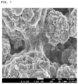
- FIG. 7 is an SEM image taken from an electrode of Comparative Example 3.
- FIG. 8 is an SEM image taken from an electrode of Comparative Example 4.
- the expression “specific surface area” is measured by a Brunauer-Emmett-Teller (BET) method, wherein, specifically, the specific surface area may be calculated from a nitrogen gas adsorption amount at a liquid nitrogen temperature (77K) using BELSORP-mini II by Bell Japan Inc.
- BET Brunauer-Emmett-Teller
- An electrode according to the present invention includes an electrode active material layer, wherein the electrode active material layer includes an electrode active material; polyvinylidene fluoride; and a conductive agent, wherein the conductive agent includes a carbon nanotube structure in which 2 to 5,000 single-walled carbon nanotube units are bonded to each other, and the carbon nanotube structure may be included in an amount of 0.01 wt % to 0.5 wt % in the electrode active material layer.
- the electrode may include an electrode active material layer.
- the electrode may further include a current collector, and, in this case, the electrode active material layer may be disposed on one surface or both surfaces of the current collector.
- the current collector is not particularly limited as long as it has conductivity without causing adverse chemical changes in the battery, and, for example, copper, stainless steel, aluminum, nickel, titanium, alloys thereof, these materials that are surface-treated with one of carbon, nickel, titanium, silver, or the like, or fired carbon may be used.
- the current collector may typically have a thickness of 3 ⁇ m to 500 ⁇ m, and microscopic irregularities may be formed on the surface of the collector to improve the adhesion of a negative electrode active material.
- the electrode collector for example, may be used in various shapes such as that of a film, a sheet, a foil, a net, a porous body, a foam body, a non-woven fabric body, and the like.
- the electrode active material layer may include an electrode active material; polyvinylidene fluoride; and a conductive agent.
- the electrode active material may be a positive electrode active material or negative electrode active material commonly used in the art, but types thereof are not particularly limited.
- the lithium oxide including lithium and at least one metal such as cobalt, manganese, nickel, or aluminum
- the lithium oxide may include lithium-manganese-based oxide (e.g., LiMnO 2 , LiMn 2 O 4 , etc.), lithium-cobalt-based oxide (e.g., LiCoO 2 , etc.), lithium-nickel-based oxide (e.g., LiNiO 2 , etc.), lithium-nickel-manganese-based oxide (e.g., LiNi 1 ⁇ Y1 Mn Y1 O 2 (where 0 ⁇ Y1 ⁇ 1), LiMn 2 ⁇ Z1 Ni z1 O 4 (where 0 ⁇ Z1 ⁇ 2), etc.), lithium-nickel-cobalt-based oxide (e.g., LiNi 1 ⁇ Y2 Co Y2 O 2 (where 0 ⁇ Y2 ⁇ 1), lithium-manganese-cobalt-based oxide (e.g.
- the negative electrode active material may include a carbonaceous material such as artificial graphite, natural graphite, graphitized carbon fibers, and amorphous carbon; a metallic compound alloyable with lithium such as silicon (Si), aluminum (Al), tin (Sn), lead (Pb), zinc (Zn), bismuth (Bi), indium (In), magnesium (Mg), gallium (Ga), cadmium (Cd), a Si alloy, a Sn alloy, or an Al alloy; a metal oxide which may be doped and undoped with lithium such as SiO v (0 ⁇ v ⁇ 2), SnO 2 , vanadium oxide, and lithium vanadium oxide; or a composite including the metallic compound and the carbonaceous material such as a Si—C composite or a Sn—C composite, and any one thereof or a mixture of two or more thereof may be used.
- a metallic lithium thin film may be used as the negative electrode active material.
- both low crystalline carbon and high crystalline carbon may be used as the
- the above-described electrode active material may be included in an amount of 70 wt % to 99.5 wt %, for example, 80 wt % to 99 wt % based on a total weight of the electrode active material layer.
- amount of the electrode active material satisfies the above range, excellent energy density, electrode adhesion, and electrical conductivity may be achieved.
- the conductive agent may include a carbon nanotube structure.
- the carbon nanotube structure may include a plurality of single-walled carbon nanotube units.
- the carbon nanotube structure may be a carbon nanotube structure in which 2 to 5,000 single-walled carbon nanotube units are bonded to each other, and, more specifically, the carbon nanotube structure may be a carbon nanotube structure in which 2 to 4,500 single-walled carbon nanotube units are bonded to each other. More specifically, in consideration of dispersibility of the carbon nanotube structure and durability of the electrode, the carbon nanotube structure is most preferably a carbon nanotube structure in which 2 to 50 single-walled carbon nanotube units are bonded to each other.
- the single-walled carbon nanotube units may be arranged side by side and bonded in the carbon nanotube structure (cylindrical structure having flexibility in which the units are bonded such that long axes of the units are parallel to each other) to form the carbon nanotube structure.
- the carbon nanotube structures are interconnected in the electrode to form a network structure.
- Typical electrodes including carbon nanotubes are generally prepared by preparing a conductive agent dispersion by dispersing bundle type or entangled type carbon nanotubes (form in which single-walled carbon nanotube units or multi-walled carbon nanotube units are attached or entangled with each other) in a dispersion medium and then using the conductive dispersion.
- the carbon nanotubes are fully dispersed in the typical conductive agent dispersion, the carbon nanotubes are present as the conductive agent dispersion in which single-stranded carbon nanotube units are dispersed.
- the typical conductive agent dispersion since the carbon nanotube units are easily cut by an excessive dispersion process, the carbon nanotube units have a length shorter than an initial length.
- the carbon nanotube units may also be easily cut during a rolling process of the electrode, and the carbon nanotube unit may additionally be cut due to changes in volume of the electrode active material during operation of the battery. Accordingly, since conductivity of the electrode is reduced, input characteristics, output characteristics, and life characteristics of the battery may be degraded. Furthermore, with respect to the multi-walled carbon nanotube units, structural defects are high due to a mechanism in which nodes grow (the units are not smooth and linear, but the nodes are present due to defects generated during the growth process). Thus, the multi-walled carbon nanotube units are more easily cut in the dispersion process, and the short-cut multi-walled carbon nanotube units may be easily aggregated by n-n stacking caused by carbon of the unit. Accordingly, it is more difficult for the multi-walled carbon nanotube units to be more uniformly dispersed in an electrode slurry.
- the carbon nanotube structure included in the electrode of the present invention since the carbon nanotube structure is in the form in which 2 to 5,000 single-walled carbon nanotube units maintaining relatively high crystallinity without structural defects are bonded together side by side, the single-walled carbon nanotube units may not be cut even during the operation of the battery and their length may be smoothly maintained. Thus, the conductivity of the electrode may be maintained. Also, since the conductivity of the electrode is increased due to high conductivity of the single-walled carbon nanotube unit having high crystallinity, the input characteristics, output characteristics, and life characteristics of the battery may be significantly improved.
- the carbon nanotube structures are interconnected in the electrode to have a network structure, an excessive change in the volume of the electrode active material may be suppressed, a strong conductive path may be secured at the same time, and electrode adhesion may be significantly improved by inhibiting deintercalation of the electrode active material.
- the single-walled carbon nanotube unit may have an average diameter of 0.5 nm to 10 nm, particularly 1 nm to 9 nm, and more particularly 1 nm to 6 nm.
- the average diameter corresponds to an average value of top 100 single-walled carbon nanotubes with a larger average diameter and bottom 100 single-walled carbon nanotubes when the prepared electrode is observed by a transmission electron microscope (TEM).
- TEM transmission electron microscope
- the single-walled carbon nanotube unit may have an average length of 1 ⁇ m to 100 ⁇ m, for example, 5 ⁇ m to 50 ⁇ m.
- the average length corresponds to an average value of top 100 single-walled carbon nanotubes with a larger average length and bottom 100 single-walled carbon nanotubes when the prepared electrode is observed by a TEM.
- the single-walled carbon nanotube unit may have a specific surface area of 500 m 2 /g to 1,000 m 2 /g, for example, 600 m 2 /g to 800 m 2 /g.
- the specific surface area of the single-walled carbon nanotube unit may specifically be calculated from a nitrogen gas adsorption amount at a liquid nitrogen temperature (77K) using BELSORP-mini II by Bell Japan Inc.
- the carbon nanotube structure may have an average diameter of 1 nm to 300 nm, for example, 3 nm to 150 nm.
- the average diameter corresponds to an average value of diameters of top 100 single-walled carbon nanotubes with a larger average diameter and bottom 100 single-walled carbon nanotubes when the prepared electrode is observed by a scanning electron microscope (SEM).
- the carbon nanotube structure may have an average length of 1 ⁇ m to 100 ⁇ m, for example, 5 ⁇ m to 50 ⁇ m.
- the average length corresponds to an average value of lengths of top 100 single-walled carbon nanotubes with a larger average length and bottom 100 single-walled carbon nanotubes when the prepared electrode is observed by an SEM.
- the carbon nanotube structure may be included in an amount of 0.01 wt % to 0.5 wt % in the electrode active material layer, and may specifically be included in an amount of 0.02 wt % to 0.2 wt %.
- the amount of the carbon nanotube structure satisfies the above range, since the conductive path in the electrode may be secured, the life characteristics of the battery may be improved while electrode resistance is maintained at a low level.
- the carbon nanotube structure is not generated, or is generated in a very small amount (for example, 0.0005 wt %) even if it is unintentionally generated. That is, the above amount range may never be achieved in the usual way.
- an electrode includes a multi-walled carbon nanotube unit
- a large amount (for example, greater than 0.5 wt %) of the multi-walled carbon nanotube unit has to be used to compensate for low conductivity of the multi-walled carbon nanotube unit.
- an electrode is prepared by using a conductive agent dispersion in which single-walled carbon nanotube units are fully dispersed, a small amount of the single-walled carbon nanotube units may not be used due to a limitation where the single-walled carbon nanotube units are cut.
- the carbon nanotube structure included in the electrode of the present invention is in the form in which 2 to 5,000 single-walled carbon nanotube units are bonded together side by side.
- the conductivity of the electrode may be maintained and the conductivity of the electrode may be smoothly secured due to the high conductivity of the single-walled carbon nanotube unit. Accordingly, the input characteristics, output characteristics, and life characteristics of the battery may be excellent even if the amount of the carbon nanotube structure in the electrode is low.
- the single-walled carbon nanotube unit may be surface-treated through an oxidation treatment or nitridation treatment to improve affinity of polyvinylidene fluoride.
- the polyvinylidene fluoride may be a substance that starts to be included in the electrode from the conductive agent dispersion necessary for the preparation of the electrode slurry (in some cases, the polyvinylidene fluoride may be further added to reinforce a binder function during the preparation of the electrode slurry).
- the polyvinylidene fluoride helps to facilitate the dispersion of the bundle-type carbon nanotubes in the conductive agent dispersion.
- the polyvinylidene fluoride may have a weight-average molecular weight of 10,000 g/mol to 1,000,000 g/mol, for example, 100,000 g/mol to 900,000 g/mol.
- the weight-average molecular weight satisfies the above range, since the polyvinylidene fluoride may easily penetrate between the single-walled carbon nanotube units in the bundle type carbon nanotubes, the bundle type carbon nanotubes may be appropriately dispersed and phase stability of the conductive agent dispersion may be improved.
- the polyvinylidene fluoride may be included in an amount of 0.1 wt % to 10.0 wt %, particularly 0.2 wt % to 5.0 wt %, and more particularly 0.2 wt % to 2.5 wt % in the electrode active material layer.
- the amount of the polyvinylidene fluoride satisfies the above range, the carbon nanotube structures are uniformly dispersed, energy density of the electrode is high, and the electrode adhesion may be excellent.
- the polyvinylidene fluoride may include modified polyvinylidene fluoride which is modified with a hydrophilic functional group to improve affinity with the single-walled carbon nanotube unit.
- the polyvinylidene fluoride may include modified polyvinylidene fluoride including at least one functional group selected from an acid functional group and an ester functional group.
- the functional groups of the modified polyvinylidene fluoride may interact with the single-walled carbon nanotube unit to further improve the electrode adhesion while improving the dispersibility of the carbon nanotube structure.
- the functional group may be included in an amount of 0.1 wt % to 5 wt %, for example, 0.3 wt % to 3 wt % in the modified polyvinylidene fluoride.
- the electrode adhesion may be further improved while further improving the dispersibility of the carbon nanotube structure.
- the modified polyvinylidene fluoride may be included in an amount of 1 wt % to 100 wt %, particularly 1 wt % to 50 wt %, and more particularly 1 wt % to 20 wt % based on a total weight of the polyvinylidene fluoride.
- the electrode adhesion may be further improved while further increasing the dispersibility of the carbon nanotube structure.
- the electrode active material layer may further include a binder.
- the binder is for securing adhesion between the electrode active materials and adhesion of the electrode active material to the current collector, wherein common binders used in the art may be used, and types thereof are not particularly limited.
- the binder may include polyvinylidene fluoride-hexafluoropropylene copolymer (PVDF-co-HFP), polyvinyl alcohol, polyacrylonitrile, carboxymethyl cellulose (CMC), starch, hydroxypropyl cellulose, regenerated cellulose, polyvinylpyrrolidone, tetrafluoroethylene, polyethylene, polypropylene, an ethylene-propylene-diene monomer (EPDM), a sulfonated-EPDM, a styrene-butadiene rubber (SBR), a fluorine rubber, or copolymers thereof, and any one thereof or a mixture of two or more thereof may be used.
- PVDF-co-HFP polyvinylidene fluoride-hexafluoropropylene copolymer
- CMC carboxymethyl cellulose
- SBR styrene-butadiene rubber
- the binder may be included in an amount of 10 wt % or less, for example, 0.1 wt % to 5 wt % based on the total weight of the electrode active material layer. In a case in which the amount of the binder satisfies the above range, excellent electrode adhesion may be achieved while minimizing an increase in the electrode resistance.
- the electrode of the present invention configured as described above has excellent electrode adhesion.
- the electrode according to the present invention may have an adhesion measured by a 90° peel test of 20.2 gf/20 mm or more, for example, 21 gf/20 mm or more.
- the method of preparing the electrode of the present invention includes the steps of: (1) preparing a mixture by adding bundle type single-walled carbon nanotubes and polyvinylidene fluoride to a dispersion medium; (2) preparing a conductive agent dispersion including a carbon nanotube structure, in which 2 to 5,000 single-walled carbon nanotube units are bonded to each other, by sonication of the mixture; and (3) forming an electrode slurry including the conductive agent dispersion and an electrode active material, wherein the carbon nanotube structure is included in an amount of 0.01 wt % to 0.5 wt % in a solid content of the electrode slurry.
- the electrode of the above-described embodiment may be prepared by the above method.
- the mixture may be prepared by adding bundle type carbon nanotubes and polyvinylidene fluoride to a dispersion medium.
- the bundle type carbon nanotubes are present in the form of a bundle in which the above-described single-walled carbon nanotube units are bonded, wherein the bundle type carbon nanotube includes usually 2 or more, substantially 500 or more, for example, 5,000 or more single-walled carbon nanotube units.
- the bundle type single-walled carbon nanotubes may be included in an amount of 0.1 wt % to 1.0 wt %, for example, 0.2 wt % to 0.5 wt % in the mixture.
- amount of the bundle type single-walled carbon nanotubes satisfies the above range, since the bundle type single-walled carbon nanotubes are dispersed in an appropriate level, a carbon nanotube structure may be formed at an appropriate level and dispersion stability may be improved.
- the polyvinylidene fluoride may be included in an amount of 0.1 wt % to 20 wt %, for example, 1 wt % to 10 wt % in the mixture.
- the amount of the polyvinylidene fluoride satisfies the above range, since the bundle type single-walled carbon nanotubes are dispersed in an appropriate level, a carbon nanotube structure may be formed at an appropriate level and the dispersion stability may be improved.
- polyvinylidene fluoride is the same as the polyvinylidene fluoride of the above-described embodiment, a description thereof will be omitted.
- a weight ratio of the bundle type carbon nanotubes to the polyvinylidene fluoride may be in a range of 1:0.1 to 1:10, for example, 1:1 to 1:10.
- the weight ratio satisfies the above range, since the bundle type single-walled carbon nanotubes are dispersed in an appropriate level, a carbon nanotube structure may be formed at an appropriate level and the dispersion stability may be improved.
- the dispersion medium may include an amide-based polar organic solvent such as dimethylformamide (DMF), diethylformamide, dimethylacetamide (DMAc), and N-methylpyrrolidone (NMP); alcohols such as methanol, ethanol, 1-propanol, 2-propanol (isopropyl alcohol), 1-butanol (n-butanol), 2-methyl-1-propanol (isobutanol), 2-butanol (sec-butanol), 2-methyl-2-propanol (tert-butanol), pentanol, hexanol, heptanol, or octanol; glycols such as ethylene glycol, diethylene glycol, triethylene glycol, propylene glycol, 1,3-propanediol, 1,3-butanediol, 1,5-pentanediol, or hexylene glycol; polyhydric alcohols such as g
- a solid content in the mixture may be in a range of 0.1 wt % to 20 wt %, for example, 1 wt % to 10 wt %.
- the solid content in the mixture satisfies the above range, since the bundle type single-walled carbon nanotubes are dispersed in an appropriate level, a carbon nanotube structure may be formed at an appropriate level and the dispersion stability may be improved.
- the electrode slurry may have viscosity and elasticity suitable for an electrode preparation process, and it also contributes to increase the solid content of the electrode slurry.
- a process of dispersing the bundle type carbon nanotubes in the mixture may be performed by sonication and using a mixing device such as a homogenizer, a bead mill, a ball mill, a basket mill, an attrition mill, a universal stirrer, a clear mixer, a spike mill, or a TK mixer.
- a mixing device such as a homogenizer, a bead mill, a ball mill, a basket mill, an attrition mill, a universal stirrer, a clear mixer, a spike mill, or a TK mixer.
- the sonication is preferable.
- numerous vacuum bubbles are created by extreme vibration when high-intensity ultrasonic waves are released into a solution, and these bubbles instantaneously clump together or grow, but the bubbles are violently broken in a chainwise manner by immediately following vibration.
- the bundle type carbon nanotubes may be debundled by shock wave energy.
- the sonication enables nanoscale fine dispersion of the single-walled carbon nanotubes in the bundle type carbon nanotube without cutting in a longitudinal direction thereof. For this reason, the sonication is preferable.
- the sonication may be as follows.
- a solid in the mixture may be dispersed by applying ultrasonic waves to the mixture.
- conditions under which the sonication is performed are as follows.
- the sonication may be performed at a power of 800 W to 1,500 W, and may specifically be performed at a power of 800 W to 1,200 W.
- the sonication may be performed for 0.5 hours to 5 hours, and may specifically be performed for 1 hour to 3 hours.
- the bundle type carbon nanotubes may be appropriately separated to form the carbon nanotube structure.
- the performance time means total time during which the sonication is used, and, thus, for example, if the sonication is performed several times, the performance time means total time required for performing the sonication several times.
- the above conditions are for forming the carbon nanotube structure in which 2 to 5,000 single-walled carbon nanotube units are bonded together side by side in the conductive agent dispersion prepared by appropriately dispersing the bundle type carbon nanotubes. This may be achieved only when a composition of the mixture and sonication conditions are strictly controlled.
- the conductive agent dispersion is prepared through the above-described process, the conductive agent dispersion is mixed with an electrode active material to form an electrode slurry.
- the above-described electrode active materials may be used as the electrode active material.
- a binder and a solvent may be further included in the electrode slurry, if necessary.
- the binder of the above-described embodiment may be used as the binder.
- the solvent may include an amide-based polar organic solvent such as dimethylformamide (DMF), diethylformamide, dimethylacetamide (DMAc), and N-methylpyrrolidone (NMP); alcohols such as methanol, ethanol, 1-propanol, 2-propanol (isopropyl alcohol), 1-butanol (n-butanol), 2-methyl-1-propanol (isobutanol), 2-butanol (sec-butanol), 2-methyl-2-propanol (tert-butanol), pentanol, hexanol, heptanol, or octanol; glycols such as ethylene glycol, diethylene glycol, triethylene glycol, propylene glycol, 1,3-propaned
- the electrode active material may be included in an amount of 70 wt % to 99.5 wt %, for example, 80 wt % to 99 wt % based on a total solid content in the electrode slurry.
- the amount of the electrode active material satisfies the above range, excellent energy density, electrode adhesion, and electrical conductivity may be achieved.
- the binder may be included in an amount of 10 wt % or less, for example, 0.1 wt % to 5 wt % based on the total solid content in the electrode slurry.
- a solid content in the electrode slurry may be in a range of 60 wt % to 80 wt %, for example, 65 wt % to 75 wt %.
- the solid content in the electrode slurry satisfies the above range, migration of the conductive agent and the binder caused by the evaporation of the solvent may be suppressed during drying after coating of the electrode slurry, and an electrode having excellent electrode adhesion and electrical conductivity may be prepared.
- a high-quality electrode having less deformation of the electrode during rolling may be prepared.
- the carbon nanotube structure may be included in an amount of 0.01 wt % to 0.5 wt % in the solid content of the electrode slurry, and may specifically be included in an amount of 0.02 wt % to 0.2 wt %.
- the amount of the carbon nanotube structure satisfies the above range, since the conductive path in the electrode may be secured, the life characteristics of the battery may be improved while the electrode resistance is maintained at a low level.
- the electrode slurry prepared as described above is coated and dried to form an electrode active material layer.
- the electrode active material layer may be prepared by a method of coating the electrode slurry on an electrode collector and drying the coated electrode collector, or may be prepared by a method of casting the electrode slurry on a separate support and then laminating a film separated from the support on the electrode collector. If necessary, the electrode active material layer is formed by the above-described method, and a rolling process may then be further performed.
- drying and the rolling may be performed under appropriate conditions in consideration of physical properties of the electrode to be finally prepared, and are not particularly limited.
- the secondary battery according to the present invention includes the above-described electrode of the present invention.
- the electrode may be at least one of a positive electrode and a negative electrode.
- the secondary battery according to the present invention may include a positive electrode, a negative electrode, a separator disposed between the positive electrode and the negative electrode, and an electrolyte, and, in this case, at least one of the positive electrode and the negative electrode may be the above-described electrode of the present invention, that is, the electrode which includes the electrode active material layer including the electrode active material and the carbon nanotube structure.
- the electrode of the present invention may be the positive electrode. Since the electrode according to the present invention has been described above, a detailed description thereof will be omitted, and hereinafter, only the other components will be described.
- the separator separates the negative electrode and the positive electrode and provides a movement path of lithium ions, wherein any separator may be used as the separator without particular limitation as long as it is typically used in a lithium secondary battery.
- a porous polymer film for example, a porous polymer film prepared from a polyolefin-based polymer, such as an ethylene homopolymer, a propylene homopolymer, an ethylene/butene copolymer, an ethylene/hexene copolymer, and an ethylene/methacrylate copolymer, or a laminated structure having two or more layers thereof may be used as the separator.
- a typical porous nonwoven fabric for example, a nonwoven fabric formed of high melting point glass fibers or polyethylene terephthalate fibers may be used.
- a coated separator including a ceramic component or a polymer material may be used to secure heat resistance or mechanical strength, and the separator having a single layer or multilayer structure may be selectively used.
- the electrolyte may include an organic liquid electrolyte, an inorganic liquid electrolyte, a solid polymer electrolyte, a gel-type polymer electrolyte, a solid inorganic electrolyte, or a molten-type inorganic electrolyte which may be used in the preparation of the lithium secondary battery, but the present invention is not limited thereto.
- the electrolyte may include a non-aqueous organic solvent and a metal salt.
- an aprotic solvent such as N-methyl-2-pyrrolidone, propylene carbonate, ethylene carbonate, butylene carbonate, dimethyl carbonate, diethyl carbonate, ⁇ -butyrolactone, 1,2-dimethoxy ethane, tetrahydrofuran, 2-methyl tetrahydrofuran, dimethyl sulfoxide, 1,3-dioxolane, formamide, diemthylformamide, dioxolane, acetonitrile, nitromethane, methyl formate, methyl acetate, phosphate triester, trimethoxy methane, a dioxolane derivative, sulfolane, methyl sulfolane, 1,3-dimethyl-2-imidazolidinone, a propylene carbonate derivative, a tetrahydrofuran derivative, ether, methyl propionate, and ethyl propionate
- N-methyl-2-pyrrolidone prop
- the cyclic carbonate since ethylene carbonate and propylene carbonate, as cyclic carbonate, well dissociate a lithium salt due to high permittivity as a highly viscous organic solvent, the cyclic carbonate may be preferably used. Since an electrolyte having high electrical conductivity may be prepared when the above cyclic carbonate is mixed with low viscosity, low permittivity linear carbonate, such as dimethyl carbonate and diethyl carbonate, in an appropriate ratio and used, the cyclic carbonate may be more preferably used.
- a lithium salt may be used as the metal salt, and the lithium salt is a material that is readily soluble in the non-aqueous organic solvent, wherein, for example, at least one selected from the group consisting of F ⁇ , Cl ⁇ , I ⁇ , NO 3 ⁇ , N(CN) 2 ⁇ , BF 4 ⁇ , ClO 4 ⁇ , PF 6 ⁇ , (CF 3 ) 2 PF 4 ⁇ , (CF 3 ) 3 PF 3 ⁇ , (CF 3 ) 4 PF 2 ⁇ , (CF 3 ) 5 PF ⁇ , (CF 3 ) 6 P ⁇ , CF 3 SO 3 ⁇ , CF 3 CF 2 SO 3 ⁇ , (CF 3 SO 2 ) 2 N ⁇ (FSO 2 ) 2 N ⁇ , CF 3 CF 2 (CF 3 ) 2 CO ⁇ , (CF 3 SO 2 ) 2 CH ⁇ , (SF 5 ) 3 C ⁇ , (CF 3 SO 2
- At least one additive for example, a halo-alkylene carbonate-based compound such as difluoroethylene carbonate, pyridine, triethylphosphite, triethanolamine, cyclic ether, ethylenediamine, n-glyme, hexaphosphoric triamide, a nitrobenzene derivative, sulfur, a quinone imine dye, N-substituted oxazolidinone, N,N-substituted imidazolidine, ethylene glycol dialkyl ether, an ammonium salt, pyrrole, 2-methoxy ethanol, or aluminum trichloride, may be further added to the electrolyte in addition to the electrolyte components.
- a halo-alkylene carbonate-based compound such as difluoroethylene carbonate, pyridine, triethylphosphite, triethanolamine, cyclic ether, ethylenediamine, n-glyme, hexaphosphoric
- the secondary battery according to the present invention as described above has excellent electrode adhesion in comparison to a conventional secondary battery, and has excellent life characteristics at a high temperature.
- bundle type carbon nanotubes (specific surface area of 650 m 2 /g) composed of single-walled carbon nanotube units having an average diameter of 1.5 nm and an average length of 5 ⁇ m and 2.0 parts by weight of polyvinylidene fluoride (weight-average molecular weight: 685,000 g/mol, standard homo-polymer) were mixed in 97.8 parts by weight of N-methylpyrrolidone (NMP), as a dispersion medium, to prepare a mixture such that a solid content was 2.2 wt %.
- NMP N-methylpyrrolidone
- the bundle type carbon nanotubes were dispersed in the dispersion medium by stirring the mixture by sonication and thus, a conductive agent dispersion was prepared. In this case, the sonication was performed at a power of 1,000 W for 1.5 hours.
- the conductive agent dispersion included a carbon nanotube structure in the form in which 2 to 5,000 single-walled carbon nanotube units were bonded together side by side. In the conductive agent dispersion, an amount of the carbon nanotube structure was 0.2 wt %, and an amount of the polyvinylidene fluoride was 2.0 wt %.
- a conductive agent dispersion was prepared in the same manner as in Preparation Example 1 except that the polyvinylidene fluoride was modified polyvinylidene fluoride (weight-average molecular weight: 880,000 g/mol) including an acid functional group in an amount of 2.1 wt %.
- bundle type carbon nanotubes (specific surface area of 185 m 2 /g) composed of multi-walled carbon nanotube units having an average diameter of 10 nm and an average length of 1 ⁇ m and 0.8 part by weight of modified polyvinylidene fluoride (weight-average molecular weight: 880,000 g/mol) including an acid functional group in an amount of 2.1 wt % were mixed in 95.2 parts by weight of N-methylpyrrolidone (NMP), as a dispersion medium, to prepare a mixture such that a solid content was 4.8 wt %.
- NMP N-methylpyrrolidone
- the bundle type carbon nanotubes were dispersed in the dispersion medium by stirring the mixture by sonication and thus, a conductive agent dispersion was prepared.
- the sonication was performed at a power of 1,000 W for 1.5 hours.
- an amount of the multi-walled carbon nanotube units was 4.0 wt %
- an amount of the polyvinylidene fluoride was 0.8 wt %.
- bundle type carbon nanotubes (specific surface area of 650 m 2 /g) composed of single-walled carbon nanotube units having an average diameter of 1.5 nm and an average length of 5 ⁇ m and 4.0 parts by weight of polyvinylidene fluoride (weight-average molecular weight: 220,000 g/mol, standard homo-polymer) were mixed in 95.8 parts by weight of N-methylpyrrolidone (NMP), as a dispersion medium, to prepare a mixture such that a solid content was 4.2 wt %.
- NMP N-methylpyrrolidone
- the bundle type carbon nanotubes were dispersed in the dispersion medium by stirring the mixture by sonication and thus, a conductive agent dispersion was prepared.
- the sonication was performed at a power of 2,000 W for 5 hours.
- an amount of the bundle type carbon nanotubes was 0.2 wt %, and an amount of the polyvinylidene fluoride was 4.0 wt %.
- LiNi 0.6 Co 0.2 Mn 0.2 O 2 (NCM622) and modified polyvinylidene fluoride (modified PVDF, KF9700, weight-average molecular weight: 880,000 g/mol, 2.1 wt % of acid functional group was included) were added to the conductive agent dispersion of Preparation Example 1, and N-methylpyrrolidone (NMP) was further added thereto to prepare a positive electrode slurry in which a solid content was 70.1 wt %.
- the positive electrode slurry was coated on a 20 ⁇ m thick aluminum (Al) thin film current collector, dried at 130° C., and then rolled to prepare a positive electrode including a positive electrode active material layer.
- a positive electrode was prepared in the same manner as in Example 1 except that the conductive agent dispersion of Preparation Example 2 was used instead of the conductive agent dispersion of Preparation Example 1. All the polyvinylidene fluoride included in the positive electrode was modified polyvinylidene fluoride.
- LiNi 0.6 Co 0.2 Mn 0.2 O 2 (NCM622) and modified polyvinylidene fluoride (modified PVDF, KF9700, weight-average molecular weight: 880,000 g/mol, 2.1 wt % of acid functional group was included) were added to the conductive agent dispersion of Preparation Example 2, and N-methylpyrrolidone (NMP) was further added thereto to prepare a positive electrode slurry in which a solid content was 70.1 wt %.
- the positive electrode slurry was coated on a 20 ⁇ m thick Al thin film current collector, dried at 130° C., and then rolled to prepare a positive electrode including a positive electrode active material layer.
- Carbon black having a specific surface area of 240 m 2 /g and modified polyvinylidene fluoride (modified PVDF, KF9700, weight-average molecular weight: 880,000 g/mol, 2.1 wt % of acid functional group was included) were mixed in N-methylpyrrolidone (NMP) to prepare a mixture such that a solid content was 72.0 wt %.
- NMP N-methylpyrrolidone
- the carbon black was dispersed in the dispersion medium by stirring the mixture by sonication and thus, a conductive agent dispersion was prepared. In this case, the sonication was performed at a power of 1,000 W for 1.5 hours.
- the conductive agent dispersion an amount of the carbon black was 15 wt %, and an amount of the modified polyvinylidene fluoride was 1.5 wt %.
- LiNi 0.6 Co 0.2 Mn 0.2 O 2 (NCM622) and modified polyvinylidene fluoride (modified PVDF, KF9700, weight-average molecular weight: 880,000 g/mol, 2.1 wt % of acid functional group was included) were added to the conductive agent dispersion, and N-methylpyrrolidone (NMP) was further added thereto to prepare a positive electrode slurry in which a solid content was 72.0 wt %.
- the positive electrode slurry was coated on a 20 ⁇ m thick Al thin film current collector, dried at 130° C., and then rolled to prepare a positive electrode including a positive electrode active material layer.
- LiNi 0.6 Co 0.2 Mn 0.2 O 2 (NCM622) and modified polyvinylidene fluoride (modified PVDF, KF9700, weight-average molecular weight: 880,000 g/mol, 2.1 wt % of acid functional group was included) were added to the conductive agent dispersion of Preparation Example 3, and N-methylpyrrolidone (NMP) was further added thereto to prepare a positive electrode slurry in which a solid content was 72.1 wt %.
- the positive electrode slurry was coated on a 20 ⁇ m thick Al thin film current collector, dried at 130° C., and then rolled to prepare a positive electrode including a positive electrode active material layer.
- LiNi 0.6 Co 0.2 Mn 0.2 O 2 (NCM622) and modified polyvinylidene fluoride (modified PVDF, KF9700, weight-average molecular weight: 880,000 g/mol, 2.1 wt % of acid functional group was included) were added to the conductive agent dispersion of Preparation Example 3, and N-methylpyrrolidone (NMP) was further added thereto to prepare a positive electrode slurry in which a solid content was 72.0 wt %.
- the positive electrode slurry was coated on a 20 ⁇ m thick Al thin film current collector, dried at 130° C., and then rolled to prepare a positive electrode including a positive electrode active material layer.
- a positive electrode was prepared in the same manner as in Example 3 except that the conductive agent dispersion of Preparation Example 4 was used instead of the conductive agent dispersion of Preparation Example 2. 97.9 wt % of the LiNi 0.6 Co 0.2 Mn 0.2 O 2 (NCM622), 2.05 wt % of the polyvinylidene fluoride, and 0.05 wt % of the carbon nanotube structure were included in the positive electrode active material layer. An amount of the modified polyvinylidene fluoride was 2.05 wt % based on a total weight of the polyvinylidene fluoride.
- the active material layers of the positive electrodes prepared by Examples 1 to 3 and Comparative Examples 1 to 4 were observed by a scanning electron microscope (SEM). SEM images taken from the electrodes of Examples 1 to 3 (in sequence) are illustrated in FIGS. 2 to 4 , respectively, and SEM images taken from the electrodes of Comparative Examples to 4 (in sequence) are illustrated in FIGS. 5 to 8 , respectively.
- SEM scanning electron microscope
- the positive electrode slurries used in the preparation of the positive electrodes of Examples 1 to 3 and Comparative Examples 1 to 4 were vacuum-dried at a temperature of 130° C. for 3 hours and then ground to prepare powders. Thereafter, pellets were prepared under a load of 9.8 MPa at 25° C. and a relative humidity of 50% using a Loresta GP instrument from Mitsubishi Chem. Analytec. Co., Ltd. Thereafter, powder resistance was measured by a 4-probe method. Measurement results are presented in Table 1 below.
- Adhesion of each of the positive electrodes of Examples 1 to 3 and Comparative Examples 1 to 4 was measured by a 90° peel test method.
- Each of the positive electrodes of Examples 1 to 3 and Comparative Examples 1 to 4, a negative electrode, and a 15 ⁇ m thick polyethylene-based separator were combined to prepare a mono-cell.
- graphite, SBR/CMC, and a conductive agent were mixed in a weight ratio of 96.5:2.5:1 to prepare a negative electrode slurry, and the negative electrode slurry was coated on a 10 ⁇ m thick copper foil and dried at 100° C. to prepare the negative electrode.
Landscapes
- Chemical & Material Sciences (AREA)
- Chemical Kinetics & Catalysis (AREA)
- Electrochemistry (AREA)
- General Chemical & Material Sciences (AREA)
- Engineering & Computer Science (AREA)
- Manufacturing & Machinery (AREA)
- Materials Engineering (AREA)
- Composite Materials (AREA)
- Battery Electrode And Active Subsutance (AREA)
Applications Claiming Priority (5)
| Application Number | Priority Date | Filing Date | Title |
|---|---|---|---|
| KR10-2018-0040574 | 2018-04-06 | ||
| KR20180040574 | 2018-04-06 | ||
| KR1020190040100A KR102285981B1 (ko) | 2018-04-06 | 2019-04-05 | 전극, 상기 전극을 포함하는 이차 전지, 및 상기 전극의 제조 방법 |
| KR10-2019-0040100 | 2019-04-05 | ||
| PCT/KR2019/004127 WO2019194662A1 (ko) | 2018-04-06 | 2019-04-08 | 전극, 상기 전극을 포함하는 이차 전지, 및 상기 전극의 제조 방법 |
Related Parent Applications (1)
| Application Number | Title | Priority Date | Filing Date |
|---|---|---|---|
| PCT/KR2019/004127 A-371-Of-International WO2019194662A1 (ko) | 2018-04-06 | 2019-04-08 | 전극, 상기 전극을 포함하는 이차 전지, 및 상기 전극의 제조 방법 |
Related Child Applications (1)
| Application Number | Title | Priority Date | Filing Date |
|---|---|---|---|
| US18/381,475 Continuation US20240079554A1 (en) | 2018-04-06 | 2023-10-18 | Electrode, Secondary Battery Including the Electrode, and Method of Preparing the Electrode |
Publications (2)
| Publication Number | Publication Date |
|---|---|
| US20210020907A1 US20210020907A1 (en) | 2021-01-21 |
| US11831006B2 true US11831006B2 (en) | 2023-11-28 |
Family
ID=68421277
Family Applications (2)
| Application Number | Title | Priority Date | Filing Date |
|---|---|---|---|
| US17/043,362 Active 2040-05-03 US11831006B2 (en) | 2018-04-06 | 2019-04-08 | Electrode, secondary battery including the electrode, and method of preparing the electrode |
| US18/381,475 Pending US20240079554A1 (en) | 2018-04-06 | 2023-10-18 | Electrode, Secondary Battery Including the Electrode, and Method of Preparing the Electrode |
Family Applications After (1)
| Application Number | Title | Priority Date | Filing Date |
|---|---|---|---|
| US18/381,475 Pending US20240079554A1 (en) | 2018-04-06 | 2023-10-18 | Electrode, Secondary Battery Including the Electrode, and Method of Preparing the Electrode |
Country Status (8)
| Country | Link |
|---|---|
| US (2) | US11831006B2 (https=) |
| EP (3) | EP3761417B1 (https=) |
| JP (1) | JP7164244B2 (https=) |
| KR (1) | KR102285981B1 (https=) |
| CN (2) | CN117913278A (https=) |
| ES (2) | ES2973852T3 (https=) |
| HU (1) | HUE066214T2 (https=) |
| PL (2) | PL3761417T3 (https=) |
Cited By (1)
| Publication number | Priority date | Publication date | Assignee | Title |
|---|---|---|---|---|
| WO2026080543A2 (en) | 2024-10-07 | 2026-04-16 | Forge Nano Inc. | High energy density cylindrical cells |
Families Citing this family (31)
| Publication number | Priority date | Publication date | Assignee | Title |
|---|---|---|---|---|
| EP4485599A3 (en) * | 2019-10-04 | 2025-03-26 | LG Energy Solution, Ltd. | Electrode and secondary battery including same |
| WO2021200529A1 (ja) * | 2020-03-31 | 2021-10-07 | パナソニックIpマネジメント株式会社 | 非水電解質二次電池用負極、及び非水電解質二次電池 |
| CN119170740A (zh) * | 2020-04-22 | 2024-12-20 | 株式会社Lg新能源 | 负极和包括所述负极的二次电池 |
| EP4044282A4 (en) * | 2020-04-22 | 2023-08-02 | LG Energy Solution, Ltd. | Silicon-carbon composite negative electrode active material, negative electrode comprising silicon-carbon composite negative electrode active material, and secondary battery comprising negative electrode |
| JP7547788B2 (ja) * | 2020-06-01 | 2024-09-10 | artience株式会社 | 導電材分散体、およびその製造方法 |
| EP4174981B1 (en) * | 2020-08-28 | 2025-08-06 | LG Energy Solution, Ltd. | Negative electrode and secondary battery comprising the negative electrode |
| KR102819965B1 (ko) * | 2020-09-04 | 2025-06-13 | 주식회사 엘지에너지솔루션 | 분리막 및 이를 포함하는 이차 전지 |
| WO2022086289A1 (ko) * | 2020-10-23 | 2022-04-28 | 주식회사 엘지에너지솔루션 | 음극 및 이를 포함하는 이차 전지 |
| KR102895322B1 (ko) | 2020-11-03 | 2025-12-05 | 주식회사 나노신소재 | 리튬이차전지의 음극용 슬러리 조성물 |
| KR102735311B1 (ko) | 2020-11-03 | 2024-11-28 | 주식회사 나노신소재 | 리튬이차전지의 양극용 슬러리 조성물 |
| KR20220092435A (ko) * | 2020-12-24 | 2022-07-01 | 주식회사 엘지에너지솔루션 | 리튬 이차 전지용 양극 및 이를 포함하는 리튬 이차 전지 |
| KR102942814B1 (ko) * | 2020-12-28 | 2026-03-23 | 주식회사 엘지에너지솔루션 | 음극 및 이의 제조방법 |
| KR102923829B1 (ko) * | 2021-02-08 | 2026-02-04 | 주식회사 엘지화학 | 리튬 이차 전지용 양극 및 이를 포함하는 리튬 이차 전지 |
| EP4170744A1 (en) * | 2021-03-19 | 2023-04-26 | Sekisui Chemical Co., Ltd. | Positive electrode for non-aqueous electrolyte secondary battery, and non-aqueous electrolyte secondary battery, battery module and battery system using the same |
| US20230369601A1 (en) * | 2021-03-19 | 2023-11-16 | Lg Energy Solution, Ltd. | Electrode and Secondary Battery Including the Electrode |
| KR102871298B1 (ko) * | 2021-04-30 | 2025-10-16 | 주식회사 엘지에너지솔루션 | 음극 및 상기 음극을 포함하는 이차 전지 |
| KR102785451B1 (ko) | 2021-10-01 | 2025-03-25 | 주식회사 나노신소재 | 리튬이차전지의 양극용 슬러리 조성물 |
| KR20230149256A (ko) | 2022-04-19 | 2023-10-26 | 주식회사 나노신소재 | 리튬이차전지의 양극용 슬러리 조성물 |
| GB2622037B (en) * | 2022-08-31 | 2025-01-08 | Dyson Technology Ltd | Energy storage devices and components thereof |
| KR20240042331A (ko) * | 2022-09-23 | 2024-04-02 | 주식회사 엘지에너지솔루션 | 리튬 이차 전지 |
| WO2024102352A2 (en) * | 2022-11-08 | 2024-05-16 | Propriety Inc. | Alternative solvent/binder slurry compositions for manufacture of lithium-ion battery electrodes |
| CN115763871B (zh) * | 2022-12-01 | 2025-07-01 | 中国地质大学(北京) | 一种膜电极、设备及方法 |
| WO2024130263A2 (en) * | 2022-12-12 | 2024-06-20 | Battery Electron Transport Associates, Inc. | Precision chopped fiber and nanostrand combination additive for resistance reduction in a battery and battery materials |
| WO2024138751A1 (zh) * | 2022-12-30 | 2024-07-04 | 宁德新能源科技有限公司 | 电极、二次电池和电子设备 |
| JP7414171B1 (ja) | 2023-03-10 | 2024-01-16 | 東洋インキScホールディングス株式会社 | カーボンナノチューブ分散組成物およびその利用 |
| CN116093258A (zh) * | 2023-04-11 | 2023-05-09 | 宁德新能源科技有限公司 | 正极片、二次电池以及电子设备 |
| CN116111043B (zh) * | 2023-04-11 | 2023-08-22 | 宁德新能源科技有限公司 | 正极片、二次电池以及电子设备 |
| CN117174905A (zh) * | 2023-09-01 | 2023-12-05 | 东阳利维能新能源科技有限公司 | 一种高电导性高容量正极极片、锂电池及其制备方法 |
| CN121079795A (zh) * | 2023-09-06 | 2025-12-05 | 株式会社Lg新能源 | 导电剂分散体、和通过使用其制备的电极和锂二次电池 |
| WO2025105872A1 (ko) * | 2023-11-17 | 2025-05-22 | 주식회사 엘지에너지솔루션 | 전극, 리튬 이차 전지 및 전극의 제조 방법 |
| WO2025264555A1 (en) * | 2024-06-17 | 2025-12-26 | Quantumscape Battery, Inc. | Cathode compositions and processes for making and using the same |
Citations (34)
| Publication number | Priority date | Publication date | Assignee | Title |
|---|---|---|---|---|
| US20030099883A1 (en) | 2001-10-10 | 2003-05-29 | Rosibel Ochoa | Lithium-ion battery with electrodes including single wall carbon nanotubes |
| KR20070027438A (ko) | 2005-09-06 | 2007-03-09 | 주식회사 엘지화학 | 탄소 나노튜브 함유 복합체 바인더 및 이를 포함하는 리튬이차전지 |
| US20090181309A1 (en) | 2008-01-15 | 2009-07-16 | Samsung Electronics Co., Ltd. | Electrode, lithium battery, method of manufacturing electrode, and composition for coating electrode |
| JP2010129169A (ja) | 2008-11-25 | 2010-06-10 | National Institute Of Advanced Industrial Science & Technology | 負極用カーボンナノチューブ材料およびこれを負極とするリチウムイオン二次電池 |
| WO2012114590A1 (ja) | 2011-02-23 | 2012-08-30 | 三洋電機株式会社 | 非水電解質二次電池用電極及びその製造方法並びに非水電解質二次電池 |
| US20130171516A1 (en) * | 2011-12-28 | 2013-07-04 | Hon Hai Precision Industry Co., Ltd. | Lithium ion battery electrode |
| US20130193063A1 (en) | 2010-10-14 | 2013-08-01 | Ying Yuk Ng | Nonwoven fabric, method for producing the same, and filter formed with the same |
| KR20130132550A (ko) | 2010-12-21 | 2013-12-04 | 바이엘 인텔렉쳐 프로퍼티 게엠베하 | 분말형 중합체/탄소 나노튜브 혼합물의 제조 방법 |
| WO2014088070A1 (ja) | 2012-12-05 | 2014-06-12 | 日本ゼオン株式会社 | リチウムイオン二次電池 |
| KR20140079702A (ko) | 2012-12-19 | 2014-06-27 | 삼성에스디아이 주식회사 | 리튬 이차 전지용 음극, 이의 제조 방법 및 이를 포함하는 리튬 이차 전지 |
| US20140248544A1 (en) | 2013-02-07 | 2014-09-04 | Weibing Xing | Metalized, three-dimensional structured oxygen cathode materials for lithium/air batteries and method for making and using the same |
| JP2014203804A (ja) | 2013-04-10 | 2014-10-27 | 日本ゼオン株式会社 | リチウムイオン二次電池用正極およびリチウムイオン二次電池 |
| US20140326651A1 (en) | 2011-02-28 | 2014-11-06 | Fairtech Investment Limited | Connector assembly for use in filter elements of press filter and press filter comprising the same |
| JP2015053165A (ja) | 2013-09-06 | 2015-03-19 | 日立化成株式会社 | リチウムイオン二次電池用正極及びリチウムイオン二次電池 |
| US20150083975A1 (en) | 2013-09-24 | 2015-03-26 | Samsung Sdi Co., Ltd. | Composite binder composition for secondary battery, cathode and lithium battery containing the binder composition |
| WO2015053411A1 (ja) | 2013-10-08 | 2015-04-16 | 日本ゼオン株式会社 | 金属複合材料およびその製造方法 |
| JP2015105213A (ja) | 2013-11-29 | 2015-06-08 | 日本ゼオン株式会社 | カーボンナノチューブ及びその分散液、並びに自立膜及び複合材料 |
| CN204927432U (zh) | 2015-07-03 | 2015-12-30 | 深圳市慧通天下科技股份有限公司 | 一种圆柱形锂离子动力电池 |
| JP2016048698A (ja) | 2016-01-04 | 2016-04-07 | 日立化成株式会社 | リチウムイオン二次電池正極用導電剤並びにこれを用いたリチウムイオン二次電池用正極材料、リチウムイオン二次電池用正極合剤、リチウムイオン二次電池用正極及びリチウムイオン二次電池 |
| US20160111724A1 (en) | 2013-05-31 | 2016-04-21 | Showa Denko K.K. | Negative electrode material for lithium ion secondary battery |
| KR20160066498A (ko) | 2014-12-02 | 2016-06-10 | 주식회사 엘지화학 | 이차전지용 바인더 및 이를 포함하는 이차전지 |
| JP2016190772A (ja) | 2015-03-31 | 2016-11-10 | 日本ゼオン株式会社 | 炭素膜およびその製造方法 |
| US20170077497A1 (en) | 2015-09-16 | 2017-03-16 | Samsung Electronics Co., Ltd. | Electrode active material, electrode and secondary battery including the same, and method of preparing the electrode active material |
| KR20170037458A (ko) | 2015-09-25 | 2017-04-04 | 주식회사 엘지화학 | 탄소 나노튜브 분산액 및 이의 제조방법 |
| JP2017084759A (ja) | 2015-10-30 | 2017-05-18 | 大阪瓦斯株式会社 | 電極活物質−カーボンナノチューブコンポジット及びその製造方法 |
| KR20170063402A (ko) | 2015-11-30 | 2017-06-08 | 주식회사 엘지화학 | 이차전지용 양극 및 이를 포함하는 이차전지 |
| KR20170084798A (ko) | 2016-01-13 | 2017-07-21 | 주식회사 엘지화학 | 비표면적이 큰 음극 활물질층을 포함하는 음극 및 이의 제조방법 |
| CN107104245A (zh) | 2017-05-03 | 2017-08-29 | 南京安普瑞斯有限公司 | 一种锂离子电池 |
| KR20170098146A (ko) | 2016-02-19 | 2017-08-29 | 삼성에스디아이 주식회사 | 리튬 이차 전지용 양극, 리튬 이차 전지용 권회 소자, 및 리튬 이차 전지 |
| KR20170127240A (ko) | 2016-05-11 | 2017-11-21 | 주식회사 엘지화학 | 전극, 이의 제조방법 및 이를 포함하는 리튬이차전지 |
| US20170338468A1 (en) | 2015-01-13 | 2017-11-23 | Lg Chem, Ltd. | Method of preparing composition for forming positive electrode of lithium secondary battery, and positive electrode and lithium secondary battery manufactured by using the composition |
| CN107681157A (zh) | 2017-08-08 | 2018-02-09 | 广州鹏辉能源科技股份有限公司 | 一种锂离子电池导电剂及其锂离子电池 |
| KR20180033746A (ko) | 2016-09-26 | 2018-04-04 | 울산과학기술원 | 삼차원구조 전극, 및 이를 포함하는 전기 화학 소자 |
| US20180159131A1 (en) * | 2015-06-12 | 2018-06-07 | Lg Chem, Ltd. | Positive electrode material mixture and secondary battery including the same |
-
2019
- 2019-04-05 KR KR1020190040100A patent/KR102285981B1/ko active Active
- 2019-04-08 JP JP2021502684A patent/JP7164244B2/ja active Active
- 2019-04-08 US US17/043,362 patent/US11831006B2/en active Active
- 2019-04-08 EP EP19781670.5A patent/EP3761417B1/en active Active
- 2019-04-08 CN CN202410043050.1A patent/CN117913278A/zh active Pending
- 2019-04-08 PL PL19781670.5T patent/PL3761417T3/pl unknown
- 2019-04-08 ES ES19781670T patent/ES2973852T3/es active Active
- 2019-04-08 CN CN201980024445.4A patent/CN111954949B/zh active Active
- 2019-04-08 PL PL24151176.5T patent/PL4329032T3/pl unknown
- 2019-04-08 EP EP25215787.0A patent/EP4672407A3/en active Pending
- 2019-04-08 EP EP24151176.5A patent/EP4329032B1/en active Active
- 2019-04-08 HU HUE19781670A patent/HUE066214T2/hu unknown
- 2019-04-08 ES ES24151176T patent/ES3061211T3/es active Active
-
2023
- 2023-10-18 US US18/381,475 patent/US20240079554A1/en active Pending
Patent Citations (45)
| Publication number | Priority date | Publication date | Assignee | Title |
|---|---|---|---|---|
| US20030099883A1 (en) | 2001-10-10 | 2003-05-29 | Rosibel Ochoa | Lithium-ion battery with electrodes including single wall carbon nanotubes |
| KR20070027438A (ko) | 2005-09-06 | 2007-03-09 | 주식회사 엘지화학 | 탄소 나노튜브 함유 복합체 바인더 및 이를 포함하는 리튬이차전지 |
| US20070202403A1 (en) | 2005-09-06 | 2007-08-30 | Eun-Suok Oh | Composite binder containing carbon nanotube and lithium secondary battery employing the same |
| US20090181309A1 (en) | 2008-01-15 | 2009-07-16 | Samsung Electronics Co., Ltd. | Electrode, lithium battery, method of manufacturing electrode, and composition for coating electrode |
| KR20090078656A (ko) | 2008-01-15 | 2009-07-20 | 삼성전자주식회사 | 전극, 리튬 전지, 전극 제조 방법 및 전극 코팅용 조성물 |
| JP2010129169A (ja) | 2008-11-25 | 2010-06-10 | National Institute Of Advanced Industrial Science & Technology | 負極用カーボンナノチューブ材料およびこれを負極とするリチウムイオン二次電池 |
| JP2017008475A (ja) | 2010-10-14 | 2017-01-12 | フェアテック インヴェストメント リミテッド | 不織布のニードルパンチフェルト生地、その製造方法、および、それにより作られたフィルター |
| US20130193063A1 (en) | 2010-10-14 | 2013-08-01 | Ying Yuk Ng | Nonwoven fabric, method for producing the same, and filter formed with the same |
| KR20130132550A (ko) | 2010-12-21 | 2013-12-04 | 바이엘 인텔렉쳐 프로퍼티 게엠베하 | 분말형 중합체/탄소 나노튜브 혼합물의 제조 방법 |
| US20140001416A1 (en) | 2010-12-21 | 2014-01-02 | Bayer Intellectual Property Gmbh | Method for producing powdery polymer/carbon nanotube mixtures |
| WO2012114590A1 (ja) | 2011-02-23 | 2012-08-30 | 三洋電機株式会社 | 非水電解質二次電池用電極及びその製造方法並びに非水電解質二次電池 |
| US20130313486A1 (en) | 2011-02-23 | 2013-11-28 | Sanyo Electric Co., Ltd. | Electrode for non-aqueous electrolyte secondary battery, method for producing same, and non-aqueous electrolyte secondary battery |
| US20140326651A1 (en) | 2011-02-28 | 2014-11-06 | Fairtech Investment Limited | Connector assembly for use in filter elements of press filter and press filter comprising the same |
| US20150218740A1 (en) | 2011-12-21 | 2015-08-06 | Fairtech Investment Limited | Needle-punched non-woven fabric, manufacturing method thereof and filter and sound absorbing material formed thereby |
| US20130171516A1 (en) * | 2011-12-28 | 2013-07-04 | Hon Hai Precision Industry Co., Ltd. | Lithium ion battery electrode |
| WO2014088070A1 (ja) | 2012-12-05 | 2014-06-12 | 日本ゼオン株式会社 | リチウムイオン二次電池 |
| KR20140079702A (ko) | 2012-12-19 | 2014-06-27 | 삼성에스디아이 주식회사 | 리튬 이차 전지용 음극, 이의 제조 방법 및 이를 포함하는 리튬 이차 전지 |
| US20140248544A1 (en) | 2013-02-07 | 2014-09-04 | Weibing Xing | Metalized, three-dimensional structured oxygen cathode materials for lithium/air batteries and method for making and using the same |
| JP2014203804A (ja) | 2013-04-10 | 2014-10-27 | 日本ゼオン株式会社 | リチウムイオン二次電池用正極およびリチウムイオン二次電池 |
| US20160111724A1 (en) | 2013-05-31 | 2016-04-21 | Showa Denko K.K. | Negative electrode material for lithium ion secondary battery |
| KR20170118968A (ko) | 2013-05-31 | 2017-10-25 | 쇼와 덴코 가부시키가이샤 | 리튬 이온 2차전지용 부극재 |
| JP2015053165A (ja) | 2013-09-06 | 2015-03-19 | 日立化成株式会社 | リチウムイオン二次電池用正極及びリチウムイオン二次電池 |
| US20150083975A1 (en) | 2013-09-24 | 2015-03-26 | Samsung Sdi Co., Ltd. | Composite binder composition for secondary battery, cathode and lithium battery containing the binder composition |
| KR20150033439A (ko) | 2013-09-24 | 2015-04-01 | 삼성에스디아이 주식회사 | 2차전지용 바인더 조성물, 이를 채용한 양극과 리튬전지 |
| WO2015053411A1 (ja) | 2013-10-08 | 2015-04-16 | 日本ゼオン株式会社 | 金属複合材料およびその製造方法 |
| JP2015105213A (ja) | 2013-11-29 | 2015-06-08 | 日本ゼオン株式会社 | カーボンナノチューブ及びその分散液、並びに自立膜及び複合材料 |
| KR20160066498A (ko) | 2014-12-02 | 2016-06-10 | 주식회사 엘지화학 | 이차전지용 바인더 및 이를 포함하는 이차전지 |
| US20170338468A1 (en) | 2015-01-13 | 2017-11-23 | Lg Chem, Ltd. | Method of preparing composition for forming positive electrode of lithium secondary battery, and positive electrode and lithium secondary battery manufactured by using the composition |
| JP2016190772A (ja) | 2015-03-31 | 2016-11-10 | 日本ゼオン株式会社 | 炭素膜およびその製造方法 |
| US20180159131A1 (en) * | 2015-06-12 | 2018-06-07 | Lg Chem, Ltd. | Positive electrode material mixture and secondary battery including the same |
| CN204927432U (zh) | 2015-07-03 | 2015-12-30 | 深圳市慧通天下科技股份有限公司 | 一种圆柱形锂离子动力电池 |
| US20170077497A1 (en) | 2015-09-16 | 2017-03-16 | Samsung Electronics Co., Ltd. | Electrode active material, electrode and secondary battery including the same, and method of preparing the electrode active material |
| KR20170033123A (ko) | 2015-09-16 | 2017-03-24 | 삼성전자주식회사 | 전극 활물질, 이를 포함하는 전극 및 이차전지, 및 상기 전극 활물질의 제조방법 |
| US20180269485A1 (en) | 2015-09-25 | 2018-09-20 | Lg Chem, Ltd. | Carbon nanotube dispersion and method for producing same |
| KR20170037458A (ko) | 2015-09-25 | 2017-04-04 | 주식회사 엘지화학 | 탄소 나노튜브 분산액 및 이의 제조방법 |
| JP2017084759A (ja) | 2015-10-30 | 2017-05-18 | 大阪瓦斯株式会社 | 電極活物質−カーボンナノチューブコンポジット及びその製造方法 |
| KR20170063402A (ko) | 2015-11-30 | 2017-06-08 | 주식회사 엘지화학 | 이차전지용 양극 및 이를 포함하는 이차전지 |
| US20180248195A1 (en) | 2015-11-30 | 2018-08-30 | Lg Chem, Ltd. | Positive electrode for secondary battery and secondary battery including the same |
| JP2016048698A (ja) | 2016-01-04 | 2016-04-07 | 日立化成株式会社 | リチウムイオン二次電池正極用導電剤並びにこれを用いたリチウムイオン二次電池用正極材料、リチウムイオン二次電池用正極合剤、リチウムイオン二次電池用正極及びリチウムイオン二次電池 |
| KR20170084798A (ko) | 2016-01-13 | 2017-07-21 | 주식회사 엘지화학 | 비표면적이 큰 음극 활물질층을 포함하는 음극 및 이의 제조방법 |
| KR20170098146A (ko) | 2016-02-19 | 2017-08-29 | 삼성에스디아이 주식회사 | 리튬 이차 전지용 양극, 리튬 이차 전지용 권회 소자, 및 리튬 이차 전지 |
| KR20170127240A (ko) | 2016-05-11 | 2017-11-21 | 주식회사 엘지화학 | 전극, 이의 제조방법 및 이를 포함하는 리튬이차전지 |
| KR20180033746A (ko) | 2016-09-26 | 2018-04-04 | 울산과학기술원 | 삼차원구조 전극, 및 이를 포함하는 전기 화학 소자 |
| CN107104245A (zh) | 2017-05-03 | 2017-08-29 | 南京安普瑞斯有限公司 | 一种锂离子电池 |
| CN107681157A (zh) | 2017-08-08 | 2018-02-09 | 广州鹏辉能源科技股份有限公司 | 一种锂离子电池导电剂及其锂离子电池 |
Non-Patent Citations (12)
| Title |
|---|
| A. V. Krestinin et al., Characterization of SWCNT Products Manufactured in Russia and the Prospects for Their Industrial Application, 12 pages, Apr. 9, 2015, Nanotechnologies in Russia, vol. 10, Nos. 7-8, 2015. |
| Chen, Q. et al., " Aggregation behavior of single-walled carbon nanotubes in dilute aqueous suspension" Journal of Colloid and Interface Science, Elsevier, Sep. 2004, pp. 91-97, vol. 280, Issue 1. |
| Extended European Search Report including Written Opinion for Application No. 19781670.5 dated Mar. 19, 2021, 7 pages. |
| Kawasaki, S. " Physical and chemical modification and material evaluation of single-walled carbon nanotubes" 30th Tokai young ceramist meeting, 2004 autumn conference, pp. 1-16. |
| Krestinin, A.V. et al., "Characterization of SWCNT Products Manufactured in Russia and the Prospects for Their Industrial Application" Nanotechnologies in Russia, Springer Link, Apr. 2015, pp. 537-548, vol. 10, Nos. 7-8. |
| Kusumoto Chemicals Co., Ltd., Single Layer Carbon Nanotube—TUBALLTMBATT, TUBALLTMFOIL Series, 3 pages, 2017, JETI vol. 65, No. 5, 2017. |
| Kusumoto K. Co., Ltd. " Single Layer Carbon Nanotube TUBALL TM BATT, TUBALL TM FOIL Series" JETI, May 2017, pp. 51-53, vol. 65, No. 5. |
| Mikhail Predtechenskiy et al., SWCNT vs MWCNT and Nanofibers. Applications in lithium-ion batteries and transparent conductive films, 3 pages, Jun. 14, 2015, Advanced Materials: TechConnect Briefs 2015, 115. |
| Predtechenskiy, M. et al., " SWCNT vs MWCNT and Nanofibers. Applications in Lithium-Ion Batteries and Transparent Conductive Films" TechConnect Briefs 2015, Advanced Materials, Jun. 2015, pp. 115-117, vol. 115, ISBN: 978-1-4987-4727-1. |
| Search Report dated Dec. 30, 2022 from the Office Action for Chinese Application No. 201980024445.4 dated Jan. 6, 2023, pp. 1-2. [See p. 1, categorizing the cited references]. |
| Search report from International Application No. PCT/KR2019/004127, dated Jul. 12, 2019. |
| Third Party Observation for European Application No. 19781670.5, dated Jan. 4, 2023, pp. 1-7. |
Cited By (1)
| Publication number | Priority date | Publication date | Assignee | Title |
|---|---|---|---|---|
| WO2026080543A2 (en) | 2024-10-07 | 2026-04-16 | Forge Nano Inc. | High energy density cylindrical cells |
Also Published As
| Publication number | Publication date |
|---|---|
| JP2021517352A (ja) | 2021-07-15 |
| US20210020907A1 (en) | 2021-01-21 |
| KR20190117387A (ko) | 2019-10-16 |
| JP7164244B2 (ja) | 2022-11-01 |
| PL3761417T3 (pl) | 2024-05-13 |
| CN111954949B (zh) | 2024-02-02 |
| EP4672407A2 (en) | 2025-12-31 |
| ES3061211T3 (en) | 2026-03-31 |
| EP3761417B1 (en) | 2024-02-21 |
| PL4329032T3 (pl) | 2026-03-23 |
| EP4672407A3 (en) | 2026-04-01 |
| ES2973852T3 (es) | 2024-06-24 |
| US20240079554A1 (en) | 2024-03-07 |
| EP3761417A1 (en) | 2021-01-06 |
| EP4329032A3 (en) | 2024-05-29 |
| EP4329032B1 (en) | 2025-12-24 |
| CN111954949A (zh) | 2020-11-17 |
| KR102285981B1 (ko) | 2021-08-05 |
| CN117913278A (zh) | 2024-04-19 |
| EP3761417A4 (en) | 2021-04-21 |
| HUE066214T2 (hu) | 2024-07-28 |
| EP4329032A2 (en) | 2024-02-28 |
Similar Documents
| Publication | Publication Date | Title |
|---|---|---|
| US20240079554A1 (en) | Electrode, Secondary Battery Including the Electrode, and Method of Preparing the Electrode | |
| US20220320518A1 (en) | Electrode and Secondary Battery Including the Same | |
| US20220216480A1 (en) | Positive Electrode and Secondary Battery Including the Same | |
| CN113661586B (zh) | 电极和包括所述电极的二次电池 | |
| CN114127982B (zh) | 电极和包括该电极的二次电池 | |
| CN113906596B (zh) | 电极和包括该电极的二次电池 | |
| JP2025106474A (ja) | 電極および前記電極を含む二次電池 |
Legal Events
| Date | Code | Title | Description |
|---|---|---|---|
| FEPP | Fee payment procedure |
Free format text: ENTITY STATUS SET TO UNDISCOUNTED (ORIGINAL EVENT CODE: BIG.); ENTITY STATUS OF PATENT OWNER: LARGE ENTITY |
|
| AS | Assignment |
Owner name: LG CHEM, LTD., KOREA, REPUBLIC OF Free format text: ASSIGNMENT OF ASSIGNORS INTEREST;ASSIGNORS:KIM, SEUL KI;KIM, TAE GON;KIM, JE YOUNG;AND OTHERS;REEL/FRAME:053928/0842 Effective date: 20191111 |
|
| STPP | Information on status: patent application and granting procedure in general |
Free format text: APPLICATION DISPATCHED FROM PREEXAM, NOT YET DOCKETED |
|
| STPP | Information on status: patent application and granting procedure in general |
Free format text: DOCKETED NEW CASE - READY FOR EXAMINATION |
|
| AS | Assignment |
Owner name: LG ENERGY SOLUTION, LTD., KOREA, REPUBLIC OF Free format text: ASSIGNMENT OF ASSIGNORS INTEREST;ASSIGNOR:LG CHEM, LTD.;REEL/FRAME:058295/0068 Effective date: 20211027 |
|
| STPP | Information on status: patent application and granting procedure in general |
Free format text: NON FINAL ACTION MAILED |
|
| STPP | Information on status: patent application and granting procedure in general |
Free format text: NON FINAL ACTION MAILED |
|
| STPP | Information on status: patent application and granting procedure in general |
Free format text: NOTICE OF ALLOWANCE MAILED -- APPLICATION RECEIVED IN OFFICE OF PUBLICATIONS |
|
| STPP | Information on status: patent application and granting procedure in general |
Free format text: AWAITING TC RESP., ISSUE FEE NOT PAID |
|
| STPP | Information on status: patent application and granting procedure in general |
Free format text: NOTICE OF ALLOWANCE MAILED -- APPLICATION RECEIVED IN OFFICE OF PUBLICATIONS |
|
| STPP | Information on status: patent application and granting procedure in general |
Free format text: PUBLICATIONS -- ISSUE FEE PAYMENT VERIFIED |
|
| STCF | Information on status: patent grant |
Free format text: PATENTED CASE |