US11831006B2 - Electrode, secondary battery including the electrode, and method of preparing the electrode - Google Patents
Electrode, secondary battery including the electrode, and method of preparing the electrode Download PDFInfo
- Publication number
- US11831006B2 US11831006B2 US17/043,362 US201917043362A US11831006B2 US 11831006 B2 US11831006 B2 US 11831006B2 US 201917043362 A US201917043362 A US 201917043362A US 11831006 B2 US11831006 B2 US 11831006B2
- Authority
- US
- United States
- Prior art keywords
- electrode
- carbon nanotube
- polyvinylidene fluoride
- active material
- conductive agent
- Prior art date
- Legal status (The legal status is an assumption and is not a legal conclusion. Google has not performed a legal analysis and makes no representation as to the accuracy of the status listed.)
- Active, expires
Links
- 238000000034 method Methods 0.000 title claims abstract description 25
- OKTJSMMVPCPJKN-UHFFFAOYSA-N Carbon Chemical group [C] OKTJSMMVPCPJKN-UHFFFAOYSA-N 0.000 claims abstract description 175
- 239000006258 conductive agent Substances 0.000 claims abstract description 80
- 239000002033 PVDF binder Substances 0.000 claims abstract description 75
- 229920002981 polyvinylidene fluoride Polymers 0.000 claims abstract description 75
- 239000002109 single walled nanotube Substances 0.000 claims abstract description 66
- 239000007772 electrode material Substances 0.000 claims abstract description 59
- 239000006185 dispersion Substances 0.000 claims description 59
- 239000011267 electrode slurry Substances 0.000 claims description 49
- 239000000203 mixture Substances 0.000 claims description 32
- 238000000527 sonication Methods 0.000 claims description 25
- 239000007787 solid Substances 0.000 claims description 24
- 125000000524 functional group Chemical group 0.000 claims description 19
- 239000002612 dispersion medium Substances 0.000 claims description 15
- 239000002253 acid Substances 0.000 claims description 10
- 238000012360 testing method Methods 0.000 claims description 3
- 125000004185 ester group Chemical group 0.000 claims 1
- 239000010410 layer Substances 0.000 description 40
- 238000002360 preparation method Methods 0.000 description 36
- 239000002041 carbon nanotube Substances 0.000 description 29
- 229910021393 carbon nanotube Inorganic materials 0.000 description 29
- SECXISVLQFMRJM-UHFFFAOYSA-N N-Methylpyrrolidone Chemical compound CN1CCCC1=O SECXISVLQFMRJM-UHFFFAOYSA-N 0.000 description 28
- 230000000052 comparative effect Effects 0.000 description 24
- 239000011230 binding agent Substances 0.000 description 14
- 239000002048 multi walled nanotube Substances 0.000 description 13
- 239000007774 positive electrode material Substances 0.000 description 13
- -1 silicon (Si) Chemical compound 0.000 description 13
- KFZMGEQAYNKOFK-UHFFFAOYSA-N Isopropanol Chemical compound CC(C)O KFZMGEQAYNKOFK-UHFFFAOYSA-N 0.000 description 12
- ZMXDDKWLCZADIW-UHFFFAOYSA-N N,N-Dimethylformamide Chemical compound CN(C)C=O ZMXDDKWLCZADIW-UHFFFAOYSA-N 0.000 description 12
- 229910011328 LiNi0.6Co0.2Mn0.2O2 Inorganic materials 0.000 description 11
- LYCAIKOWRPUZTN-UHFFFAOYSA-N Ethylene glycol Chemical compound OCCO LYCAIKOWRPUZTN-UHFFFAOYSA-N 0.000 description 10
- PXHVJJICTQNCMI-UHFFFAOYSA-N Nickel Chemical compound [Ni] PXHVJJICTQNCMI-UHFFFAOYSA-N 0.000 description 10
- 239000000843 powder Substances 0.000 description 10
- WHXSMMKQMYFTQS-UHFFFAOYSA-N Lithium Chemical compound [Li] WHXSMMKQMYFTQS-UHFFFAOYSA-N 0.000 description 9
- 229910052799 carbon Inorganic materials 0.000 description 9
- 239000003792 electrolyte Substances 0.000 description 9
- 229910052744 lithium Inorganic materials 0.000 description 9
- ZXEKIIBDNHEJCQ-UHFFFAOYSA-N isobutanol Chemical compound CC(C)CO ZXEKIIBDNHEJCQ-UHFFFAOYSA-N 0.000 description 8
- 238000005259 measurement Methods 0.000 description 8
- 238000001878 scanning electron micrograph Methods 0.000 description 8
- ZWEHNKRNPOVVGH-UHFFFAOYSA-N 2-Butanone Chemical compound CCC(C)=O ZWEHNKRNPOVVGH-UHFFFAOYSA-N 0.000 description 6
- YEJRWHAVMIAJKC-UHFFFAOYSA-N 4-Butyrolactone Chemical compound O=C1CCCO1 YEJRWHAVMIAJKC-UHFFFAOYSA-N 0.000 description 6
- CSCPPACGZOOCGX-UHFFFAOYSA-N Acetone Chemical compound CC(C)=O CSCPPACGZOOCGX-UHFFFAOYSA-N 0.000 description 6
- IJGRMHOSHXDMSA-UHFFFAOYSA-N Atomic nitrogen Chemical compound N#N IJGRMHOSHXDMSA-UHFFFAOYSA-N 0.000 description 6
- LFQSCWFLJHTTHZ-UHFFFAOYSA-N Ethanol Chemical compound CCO LFQSCWFLJHTTHZ-UHFFFAOYSA-N 0.000 description 6
- XEKOWRVHYACXOJ-UHFFFAOYSA-N Ethyl acetate Chemical compound CCOC(C)=O XEKOWRVHYACXOJ-UHFFFAOYSA-N 0.000 description 6
- OKKJLVBELUTLKV-UHFFFAOYSA-N Methanol Chemical compound OC OKKJLVBELUTLKV-UHFFFAOYSA-N 0.000 description 6
- DNIAPMSPPWPWGF-UHFFFAOYSA-N Propylene glycol Chemical compound CC(O)CO DNIAPMSPPWPWGF-UHFFFAOYSA-N 0.000 description 6
- 239000006229 carbon black Substances 0.000 description 6
- MTHSVFCYNBDYFN-UHFFFAOYSA-N diethylene glycol Chemical compound OCCOCCO MTHSVFCYNBDYFN-UHFFFAOYSA-N 0.000 description 6
- BDERNNFJNOPAEC-UHFFFAOYSA-N propan-1-ol Chemical compound CCCO BDERNNFJNOPAEC-UHFFFAOYSA-N 0.000 description 6
- 239000010409 thin film Substances 0.000 description 6
- KMTRUDSVKNLOMY-UHFFFAOYSA-N Ethylene carbonate Chemical compound O=C1OCCO1 KMTRUDSVKNLOMY-UHFFFAOYSA-N 0.000 description 5
- 229910052782 aluminium Inorganic materials 0.000 description 5
- XAGFODPZIPBFFR-UHFFFAOYSA-N aluminium Chemical compound [Al] XAGFODPZIPBFFR-UHFFFAOYSA-N 0.000 description 5
- IEJIGPNLZYLLBP-UHFFFAOYSA-N dimethyl carbonate Chemical compound COC(=O)OC IEJIGPNLZYLLBP-UHFFFAOYSA-N 0.000 description 5
- 230000000694 effects Effects 0.000 description 5
- 239000011572 manganese Substances 0.000 description 5
- 239000002071 nanotube Substances 0.000 description 5
- 230000008569 process Effects 0.000 description 5
- 238000005096 rolling process Methods 0.000 description 5
- 239000002904 solvent Substances 0.000 description 5
- PUPZLCDOIYMWBV-UHFFFAOYSA-N (+/-)-1,3-Butanediol Chemical compound CC(O)CCO PUPZLCDOIYMWBV-UHFFFAOYSA-N 0.000 description 4
- KBPLFHHGFOOTCA-UHFFFAOYSA-N 1-Octanol Chemical compound CCCCCCCCO KBPLFHHGFOOTCA-UHFFFAOYSA-N 0.000 description 4
- BBMCTIGTTCKYKF-UHFFFAOYSA-N 1-heptanol Chemical compound CCCCCCCO BBMCTIGTTCKYKF-UHFFFAOYSA-N 0.000 description 4
- SVTBMSDMJJWYQN-UHFFFAOYSA-N 2-methylpentane-2,4-diol Chemical compound CC(O)CC(C)(C)O SVTBMSDMJJWYQN-UHFFFAOYSA-N 0.000 description 4
- VGGSQFUCUMXWEO-UHFFFAOYSA-N Ethene Chemical compound C=C VGGSQFUCUMXWEO-UHFFFAOYSA-N 0.000 description 4
- 239000005977 Ethylene Substances 0.000 description 4
- PEDCQBHIVMGVHV-UHFFFAOYSA-N Glycerine Chemical compound OCC(O)CO PEDCQBHIVMGVHV-UHFFFAOYSA-N 0.000 description 4
- FXHOOIRPVKKKFG-UHFFFAOYSA-N N,N-Dimethylacetamide Chemical compound CN(C)C(C)=O FXHOOIRPVKKKFG-UHFFFAOYSA-N 0.000 description 4
- AMQJEAYHLZJPGS-UHFFFAOYSA-N N-Pentanol Chemical compound CCCCCO AMQJEAYHLZJPGS-UHFFFAOYSA-N 0.000 description 4
- 239000011149 active material Substances 0.000 description 4
- 229920001577 copolymer Polymers 0.000 description 4
- 150000005676 cyclic carbonates Chemical class 0.000 description 4
- 238000001035 drying Methods 0.000 description 4
- 229910021389 graphene Inorganic materials 0.000 description 4
- ZSIAUFGUXNUGDI-UHFFFAOYSA-N hexan-1-ol Chemical compound CCCCCCO ZSIAUFGUXNUGDI-UHFFFAOYSA-N 0.000 description 4
- 229910003002 lithium salt Inorganic materials 0.000 description 4
- 159000000002 lithium salts Chemical class 0.000 description 4
- 239000011777 magnesium Substances 0.000 description 4
- 239000007773 negative electrode material Substances 0.000 description 4
- XNLICIUVMPYHGG-UHFFFAOYSA-N pentan-2-one Chemical compound CCCC(C)=O XNLICIUVMPYHGG-UHFFFAOYSA-N 0.000 description 4
- 238000003756 stirring Methods 0.000 description 4
- 239000010936 titanium Substances 0.000 description 4
- XNWFRZJHXBZDAG-UHFFFAOYSA-N 2-METHOXYETHANOL Chemical compound COCCO XNWFRZJHXBZDAG-UHFFFAOYSA-N 0.000 description 3
- WEVYAHXRMPXWCK-UHFFFAOYSA-N Acetonitrile Chemical compound CC#N WEVYAHXRMPXWCK-UHFFFAOYSA-N 0.000 description 3
- RYGMFSIKBFXOCR-UHFFFAOYSA-N Copper Chemical compound [Cu] RYGMFSIKBFXOCR-UHFFFAOYSA-N 0.000 description 3
- WYURNTSHIVDZCO-UHFFFAOYSA-N Tetrahydrofuran Chemical compound C1CCOC1 WYURNTSHIVDZCO-UHFFFAOYSA-N 0.000 description 3
- RTAQQCXQSZGOHL-UHFFFAOYSA-N Titanium Chemical compound [Ti] RTAQQCXQSZGOHL-UHFFFAOYSA-N 0.000 description 3
- 239000002134 carbon nanofiber Substances 0.000 description 3
- 239000003575 carbonaceous material Substances 0.000 description 3
- 239000011248 coating agent Substances 0.000 description 3
- 238000000576 coating method Methods 0.000 description 3
- 239000010949 copper Substances 0.000 description 3
- 150000002148 esters Chemical group 0.000 description 3
- 239000011521 glass Substances 0.000 description 3
- 239000000463 material Substances 0.000 description 3
- 229910052751 metal Inorganic materials 0.000 description 3
- 239000002184 metal Substances 0.000 description 3
- VNWKTOKETHGBQD-UHFFFAOYSA-N methane Chemical compound C VNWKTOKETHGBQD-UHFFFAOYSA-N 0.000 description 3
- 229910052759 nickel Inorganic materials 0.000 description 3
- 239000011356 non-aqueous organic solvent Substances 0.000 description 3
- 239000004745 nonwoven fabric Substances 0.000 description 3
- 229920000642 polymer Polymers 0.000 description 3
- RUOJZAUFBMNUDX-UHFFFAOYSA-N propylene carbonate Chemical compound CC1COC(=O)O1 RUOJZAUFBMNUDX-UHFFFAOYSA-N 0.000 description 3
- 239000000243 solution Substances 0.000 description 3
- 229910052719 titanium Inorganic materials 0.000 description 3
- DNIAPMSPPWPWGF-VKHMYHEASA-N (+)-propylene glycol Chemical compound C[C@H](O)CO DNIAPMSPPWPWGF-VKHMYHEASA-N 0.000 description 2
- WNXJIVFYUVYPPR-UHFFFAOYSA-N 1,3-dioxolane Chemical compound C1COCO1 WNXJIVFYUVYPPR-UHFFFAOYSA-N 0.000 description 2
- YPFDHNVEDLHUCE-UHFFFAOYSA-N 1,3-propanediol Substances OCCCO YPFDHNVEDLHUCE-UHFFFAOYSA-N 0.000 description 2
- SBASXUCJHJRPEV-UHFFFAOYSA-N 2-(2-methoxyethoxy)ethanol Chemical compound COCCOCCO SBASXUCJHJRPEV-UHFFFAOYSA-N 0.000 description 2
- COBPKKZHLDDMTB-UHFFFAOYSA-N 2-[2-(2-butoxyethoxy)ethoxy]ethanol Chemical compound CCCCOCCOCCOCCO COBPKKZHLDDMTB-UHFFFAOYSA-N 0.000 description 2
- WFSMVVDJSNMRAR-UHFFFAOYSA-N 2-[2-(2-ethoxyethoxy)ethoxy]ethanol Chemical compound CCOCCOCCOCCO WFSMVVDJSNMRAR-UHFFFAOYSA-N 0.000 description 2
- MXVMODFDROLTFD-UHFFFAOYSA-N 2-[2-[2-(2-butoxyethoxy)ethoxy]ethoxy]ethanol Chemical compound CCCCOCCOCCOCCOCCO MXVMODFDROLTFD-UHFFFAOYSA-N 0.000 description 2
- GTAKOUPXIUWZIA-UHFFFAOYSA-N 2-[2-[2-(2-ethoxyethoxy)ethoxy]ethoxy]ethanol Chemical compound CCOCCOCCOCCOCCO GTAKOUPXIUWZIA-UHFFFAOYSA-N 0.000 description 2
- POAOYUHQDCAZBD-UHFFFAOYSA-N 2-butoxyethanol Chemical compound CCCCOCCO POAOYUHQDCAZBD-UHFFFAOYSA-N 0.000 description 2
- ZNQVEEAIQZEUHB-UHFFFAOYSA-N 2-ethoxyethanol Chemical compound CCOCCO ZNQVEEAIQZEUHB-UHFFFAOYSA-N 0.000 description 2
- ALRXDIKPRCRYAU-UHFFFAOYSA-N 2-methylpropan-2-ol Chemical compound CC(C)(C)O.CC(C)(C)O ALRXDIKPRCRYAU-UHFFFAOYSA-N 0.000 description 2
- BVKZGUZCCUSVTD-UHFFFAOYSA-L Carbonate Chemical compound [O-]C([O-])=O BVKZGUZCCUSVTD-UHFFFAOYSA-L 0.000 description 2
- 229920002134 Carboxymethyl cellulose Polymers 0.000 description 2
- FBPFZTCFMRRESA-FSIIMWSLSA-N D-Glucitol Natural products OC[C@H](O)[C@H](O)[C@@H](O)[C@H](O)CO FBPFZTCFMRRESA-FSIIMWSLSA-N 0.000 description 2
- FBPFZTCFMRRESA-JGWLITMVSA-N D-glucitol Chemical compound OC[C@H](O)[C@@H](O)[C@H](O)[C@H](O)CO FBPFZTCFMRRESA-JGWLITMVSA-N 0.000 description 2
- OIFBSDVPJOWBCH-UHFFFAOYSA-N Diethyl carbonate Chemical compound CCOC(=O)OCC OIFBSDVPJOWBCH-UHFFFAOYSA-N 0.000 description 2
- XTHFKEDIFFGKHM-UHFFFAOYSA-N Dimethoxyethane Chemical compound COCCOC XTHFKEDIFFGKHM-UHFFFAOYSA-N 0.000 description 2
- IAZDPXIOMUYVGZ-UHFFFAOYSA-N Dimethylsulphoxide Chemical compound CS(C)=O IAZDPXIOMUYVGZ-UHFFFAOYSA-N 0.000 description 2
- 229920002943 EPDM rubber Polymers 0.000 description 2
- ZHNUHDYFZUAESO-UHFFFAOYSA-N Formamide Chemical compound NC=O ZHNUHDYFZUAESO-UHFFFAOYSA-N 0.000 description 2
- FYYHWMGAXLPEAU-UHFFFAOYSA-N Magnesium Chemical compound [Mg] FYYHWMGAXLPEAU-UHFFFAOYSA-N 0.000 description 2
- SUAKHGWARZSWIH-UHFFFAOYSA-N N,N‐diethylformamide Chemical compound CCN(CC)C=O SUAKHGWARZSWIH-UHFFFAOYSA-N 0.000 description 2
- ALQSHHUCVQOPAS-UHFFFAOYSA-N Pentane-1,5-diol Chemical compound OCCCCCO ALQSHHUCVQOPAS-UHFFFAOYSA-N 0.000 description 2
- 239000004698 Polyethylene Substances 0.000 description 2
- JUJWROOIHBZHMG-UHFFFAOYSA-N Pyridine Chemical compound C1=CC=NC=C1 JUJWROOIHBZHMG-UHFFFAOYSA-N 0.000 description 2
- KAESVJOAVNADME-UHFFFAOYSA-N Pyrrole Chemical compound C=1C=CNC=1 KAESVJOAVNADME-UHFFFAOYSA-N 0.000 description 2
- ZJCCRDAZUWHFQH-UHFFFAOYSA-N Trimethylolpropane Chemical compound CCC(CO)(CO)CO ZJCCRDAZUWHFQH-UHFFFAOYSA-N 0.000 description 2
- 150000001298 alcohols Chemical class 0.000 description 2
- ZIXLDMFVRPABBX-UHFFFAOYSA-N alpha-methylcyclopentanone Natural products CC1CCCC1=O ZIXLDMFVRPABBX-UHFFFAOYSA-N 0.000 description 2
- 150000001408 amides Chemical class 0.000 description 2
- 230000005540 biological transmission Effects 0.000 description 2
- MZNDIOURMFYZLE-UHFFFAOYSA-N butan-1-ol Chemical compound CCCCO.CCCCO MZNDIOURMFYZLE-UHFFFAOYSA-N 0.000 description 2
- GKMQWTVAAMITHR-UHFFFAOYSA-N butan-2-ol Chemical compound CCC(C)O.CCC(C)O GKMQWTVAAMITHR-UHFFFAOYSA-N 0.000 description 2
- 239000003795 chemical substances by application Substances 0.000 description 2
- 239000011651 chromium Substances 0.000 description 2
- 150000001875 compounds Chemical class 0.000 description 2
- 229910052802 copper Inorganic materials 0.000 description 2
- BGTOWKSIORTVQH-UHFFFAOYSA-N cyclopentanone Chemical compound O=C1CCCC1 BGTOWKSIORTVQH-UHFFFAOYSA-N 0.000 description 2
- 229940028356 diethylene glycol monobutyl ether Drugs 0.000 description 2
- XXJWXESWEXIICW-UHFFFAOYSA-N diethylene glycol monoethyl ether Chemical compound CCOCCOCCO XXJWXESWEXIICW-UHFFFAOYSA-N 0.000 description 2
- 229940075557 diethylene glycol monoethyl ether Drugs 0.000 description 2
- 229910001873 dinitrogen Inorganic materials 0.000 description 2
- 239000008151 electrolyte solution Substances 0.000 description 2
- TUEYHEWXYWCDHA-UHFFFAOYSA-N ethyl 5-methylthiadiazole-4-carboxylate Chemical compound CCOC(=O)C=1N=NSC=1C TUEYHEWXYWCDHA-UHFFFAOYSA-N 0.000 description 2
- FKRCODPIKNYEAC-UHFFFAOYSA-N ethyl propionate Chemical compound CCOC(=O)CC FKRCODPIKNYEAC-UHFFFAOYSA-N 0.000 description 2
- 239000000835 fiber Substances 0.000 description 2
- 239000010408 film Substances 0.000 description 2
- 235000011187 glycerol Nutrition 0.000 description 2
- 150000002334 glycols Chemical class 0.000 description 2
- 229940051250 hexylene glycol Drugs 0.000 description 2
- WGCNASOHLSPBMP-UHFFFAOYSA-N hydroxyacetaldehyde Natural products OCC=O WGCNASOHLSPBMP-UHFFFAOYSA-N 0.000 description 2
- 229910000765 intermetallic Inorganic materials 0.000 description 2
- 150000002576 ketones Chemical class 0.000 description 2
- 239000007788 liquid Substances 0.000 description 2
- 239000011244 liquid electrolyte Substances 0.000 description 2
- FUJCRWPEOMXPAD-UHFFFAOYSA-N lithium oxide Chemical compound [Li+].[Li+].[O-2] FUJCRWPEOMXPAD-UHFFFAOYSA-N 0.000 description 2
- 229910001947 lithium oxide Inorganic materials 0.000 description 2
- 229910052749 magnesium Inorganic materials 0.000 description 2
- TZIHFWKZFHZASV-UHFFFAOYSA-N methyl formate Chemical compound COC=O TZIHFWKZFHZASV-UHFFFAOYSA-N 0.000 description 2
- 239000010955 niobium Substances 0.000 description 2
- 229910052757 nitrogen Inorganic materials 0.000 description 2
- 239000003960 organic solvent Substances 0.000 description 2
- JCGNDDUYTRNOFT-UHFFFAOYSA-N oxolane-2,4-dione Chemical compound O=C1COC(=O)C1 JCGNDDUYTRNOFT-UHFFFAOYSA-N 0.000 description 2
- WXZMFSXDPGVJKK-UHFFFAOYSA-N pentaerythritol Chemical compound OCC(CO)(CO)CO WXZMFSXDPGVJKK-UHFFFAOYSA-N 0.000 description 2
- 239000003495 polar organic solvent Substances 0.000 description 2
- 229920000573 polyethylene Polymers 0.000 description 2
- 239000005518 polymer electrolyte Substances 0.000 description 2
- 229920006254 polymer film Polymers 0.000 description 2
- 229920000166 polytrimethylene carbonate Polymers 0.000 description 2
- 229960000380 propiolactone Drugs 0.000 description 2
- 150000003839 salts Chemical class 0.000 description 2
- 230000035939 shock Effects 0.000 description 2
- 239000002356 single layer Substances 0.000 description 2
- 239000002002 slurry Substances 0.000 description 2
- 239000000600 sorbitol Substances 0.000 description 2
- 238000001179 sorption measurement Methods 0.000 description 2
- 230000007847 structural defect Effects 0.000 description 2
- 229920003048 styrene butadiene rubber Polymers 0.000 description 2
- 239000000126 substance Substances 0.000 description 2
- 150000005846 sugar alcohols Polymers 0.000 description 2
- JBQYATWDVHIOAR-UHFFFAOYSA-N tellanylidenegermanium Chemical compound [Te]=[Ge] JBQYATWDVHIOAR-UHFFFAOYSA-N 0.000 description 2
- XOLBLPGZBRYERU-UHFFFAOYSA-N tin dioxide Chemical compound O=[Sn]=O XOLBLPGZBRYERU-UHFFFAOYSA-N 0.000 description 2
- ZIBGPFATKBEMQZ-UHFFFAOYSA-N triethylene glycol Chemical compound OCCOCCOCCO ZIBGPFATKBEMQZ-UHFFFAOYSA-N 0.000 description 2
- JLGLQAWTXXGVEM-UHFFFAOYSA-N triethylene glycol monomethyl ether Chemical compound COCCOCCOCCO JLGLQAWTXXGVEM-UHFFFAOYSA-N 0.000 description 2
- PYOKUURKVVELLB-UHFFFAOYSA-N trimethyl orthoformate Chemical compound COC(OC)OC PYOKUURKVVELLB-UHFFFAOYSA-N 0.000 description 2
- ZZXUZKXVROWEIF-UHFFFAOYSA-N 1,2-butylene carbonate Chemical compound CCC1COC(=O)O1 ZZXUZKXVROWEIF-UHFFFAOYSA-N 0.000 description 1
- CYSGHNMQYZDMIA-UHFFFAOYSA-N 1,3-Dimethyl-2-imidazolidinon Chemical compound CN1CCN(C)C1=O CYSGHNMQYZDMIA-UHFFFAOYSA-N 0.000 description 1
- JWUJQDFVADABEY-UHFFFAOYSA-N 2-methyltetrahydrofuran Chemical compound CC1CCCO1 JWUJQDFVADABEY-UHFFFAOYSA-N 0.000 description 1
- PPDFQRAASCRJAH-UHFFFAOYSA-N 2-methylthiolane 1,1-dioxide Chemical compound CC1CCCS1(=O)=O PPDFQRAASCRJAH-UHFFFAOYSA-N 0.000 description 1
- DSMUTQTWFHVVGQ-UHFFFAOYSA-N 4,5-difluoro-1,3-dioxolan-2-one Chemical compound FC1OC(=O)OC1F DSMUTQTWFHVVGQ-UHFFFAOYSA-N 0.000 description 1
- 229910000838 Al alloy Inorganic materials 0.000 description 1
- ZOXJGFHDIHLPTG-UHFFFAOYSA-N Boron Chemical compound [B] ZOXJGFHDIHLPTG-UHFFFAOYSA-N 0.000 description 1
- VYZAMTAEIAYCRO-UHFFFAOYSA-N Chromium Chemical compound [Cr] VYZAMTAEIAYCRO-UHFFFAOYSA-N 0.000 description 1
- LCGLNKUTAGEVQW-UHFFFAOYSA-N Dimethyl ether Chemical group COC LCGLNKUTAGEVQW-UHFFFAOYSA-N 0.000 description 1
- PIICEJLVQHRZGT-UHFFFAOYSA-N Ethylenediamine Chemical compound NCCN PIICEJLVQHRZGT-UHFFFAOYSA-N 0.000 description 1
- 229910005143 FSO2 Inorganic materials 0.000 description 1
- KRHYYFGTRYWZRS-UHFFFAOYSA-M Fluoride anion Chemical compound [F-] KRHYYFGTRYWZRS-UHFFFAOYSA-M 0.000 description 1
- YCKRFDGAMUMZLT-UHFFFAOYSA-N Fluorine atom Chemical compound [F] YCKRFDGAMUMZLT-UHFFFAOYSA-N 0.000 description 1
- GYHNNYVSQQEPJS-UHFFFAOYSA-N Gallium Chemical compound [Ga] GYHNNYVSQQEPJS-UHFFFAOYSA-N 0.000 description 1
- 229920002153 Hydroxypropyl cellulose Polymers 0.000 description 1
- XEEYBQQBJWHFJM-UHFFFAOYSA-N Iron Chemical compound [Fe] XEEYBQQBJWHFJM-UHFFFAOYSA-N 0.000 description 1
- 229910032387 LiCoO2 Inorganic materials 0.000 description 1
- 229910002993 LiMnO2 Inorganic materials 0.000 description 1
- 229910003005 LiNiO2 Inorganic materials 0.000 description 1
- 229910001290 LiPF6 Inorganic materials 0.000 description 1
- HBBGRARXTFLTSG-UHFFFAOYSA-N Lithium ion Chemical compound [Li+] HBBGRARXTFLTSG-UHFFFAOYSA-N 0.000 description 1
- 229910002097 Lithium manganese(III,IV) oxide Inorganic materials 0.000 description 1
- ZOKXTWBITQBERF-UHFFFAOYSA-N Molybdenum Chemical compound [Mo] ZOKXTWBITQBERF-UHFFFAOYSA-N 0.000 description 1
- ZHGDJTMNXSOQDT-UHFFFAOYSA-N NP(N)(N)=O.NP(N)(N)=O.NP(N)(N)=O.NP(N)(N)=O.NP(N)(N)=O.NP(N)(N)=O Chemical compound NP(N)(N)=O.NP(N)(N)=O.NP(N)(N)=O.NP(N)(N)=O.NP(N)(N)=O.NP(N)(N)=O ZHGDJTMNXSOQDT-UHFFFAOYSA-N 0.000 description 1
- 229910019142 PO4 Inorganic materials 0.000 description 1
- 239000004743 Polypropylene Substances 0.000 description 1
- 239000004372 Polyvinyl alcohol Substances 0.000 description 1
- XBDQKXXYIPTUBI-UHFFFAOYSA-M Propionate Chemical compound CCC([O-])=O XBDQKXXYIPTUBI-UHFFFAOYSA-M 0.000 description 1
- 229910000676 Si alloy Inorganic materials 0.000 description 1
- XUIMIQQOPSSXEZ-UHFFFAOYSA-N Silicon Chemical compound [Si] XUIMIQQOPSSXEZ-UHFFFAOYSA-N 0.000 description 1
- BQCADISMDOOEFD-UHFFFAOYSA-N Silver Chemical compound [Ag] BQCADISMDOOEFD-UHFFFAOYSA-N 0.000 description 1
- 229910001128 Sn alloy Inorganic materials 0.000 description 1
- 229920002472 Starch Polymers 0.000 description 1
- 239000002174 Styrene-butadiene Substances 0.000 description 1
- NINIDFKCEFEMDL-UHFFFAOYSA-N Sulfur Chemical compound [S] NINIDFKCEFEMDL-UHFFFAOYSA-N 0.000 description 1
- 238000003917 TEM image Methods 0.000 description 1
- ATJFFYVFTNAWJD-UHFFFAOYSA-N Tin Chemical compound [Sn] ATJFFYVFTNAWJD-UHFFFAOYSA-N 0.000 description 1
- GSEJCLTVZPLZKY-UHFFFAOYSA-N Triethanolamine Chemical compound OCCN(CCO)CCO GSEJCLTVZPLZKY-UHFFFAOYSA-N 0.000 description 1
- LBBLDJJXDUQFQU-UHFFFAOYSA-N [C].[C].[C] Chemical compound [C].[C].[C] LBBLDJJXDUQFQU-UHFFFAOYSA-N 0.000 description 1
- NXPZICSHDHGMGT-UHFFFAOYSA-N [Co].[Mn].[Li] Chemical compound [Co].[Mn].[Li] NXPZICSHDHGMGT-UHFFFAOYSA-N 0.000 description 1
- PFYQFCKUASLJLL-UHFFFAOYSA-N [Co].[Ni].[Li] Chemical compound [Co].[Ni].[Li] PFYQFCKUASLJLL-UHFFFAOYSA-N 0.000 description 1
- RLTFLELMPUMVEH-UHFFFAOYSA-N [Li+].[O--].[O--].[O--].[V+5] Chemical compound [Li+].[O--].[O--].[O--].[V+5] RLTFLELMPUMVEH-UHFFFAOYSA-N 0.000 description 1
- KLARSDUHONHPRF-UHFFFAOYSA-N [Li].[Mn] Chemical compound [Li].[Mn] KLARSDUHONHPRF-UHFFFAOYSA-N 0.000 description 1
- SOXUFMZTHZXOGC-UHFFFAOYSA-N [Li].[Mn].[Co].[Ni] Chemical compound [Li].[Mn].[Co].[Ni] SOXUFMZTHZXOGC-UHFFFAOYSA-N 0.000 description 1
- ZYXUQEDFWHDILZ-UHFFFAOYSA-N [Ni].[Mn].[Li] Chemical compound [Ni].[Mn].[Li] ZYXUQEDFWHDILZ-UHFFFAOYSA-N 0.000 description 1
- XHCLAFWTIXFWPH-UHFFFAOYSA-N [O-2].[O-2].[O-2].[O-2].[O-2].[V+5].[V+5] Chemical compound [O-2].[O-2].[O-2].[O-2].[O-2].[V+5].[V+5] XHCLAFWTIXFWPH-UHFFFAOYSA-N 0.000 description 1
- KXKVLQRXCPHEJC-UHFFFAOYSA-N acetic acid trimethyl ester Natural products COC(C)=O KXKVLQRXCPHEJC-UHFFFAOYSA-N 0.000 description 1
- 239000000654 additive Substances 0.000 description 1
- 230000000996 additive effect Effects 0.000 description 1
- 230000002411 adverse Effects 0.000 description 1
- 229910045601 alloy Inorganic materials 0.000 description 1
- 239000000956 alloy Substances 0.000 description 1
- VSCWAEJMTAWNJL-UHFFFAOYSA-K aluminium trichloride Chemical compound Cl[Al](Cl)Cl VSCWAEJMTAWNJL-UHFFFAOYSA-K 0.000 description 1
- 150000003863 ammonium salts Chemical class 0.000 description 1
- 229910003481 amorphous carbon Inorganic materials 0.000 description 1
- 150000001450 anions Chemical class 0.000 description 1
- 239000000010 aprotic solvent Substances 0.000 description 1
- 229910021383 artificial graphite Inorganic materials 0.000 description 1
- 239000011324 bead Substances 0.000 description 1
- 230000008901 benefit Effects 0.000 description 1
- 229910052797 bismuth Inorganic materials 0.000 description 1
- JCXGWMGPZLAOME-UHFFFAOYSA-N bismuth atom Chemical compound [Bi] JCXGWMGPZLAOME-UHFFFAOYSA-N 0.000 description 1
- 229910052796 boron Inorganic materials 0.000 description 1
- IAQRGUVFOMOMEM-UHFFFAOYSA-N butene Natural products CC=CC IAQRGUVFOMOMEM-UHFFFAOYSA-N 0.000 description 1
- 229910052793 cadmium Inorganic materials 0.000 description 1
- BDOSMKKIYDKNTQ-UHFFFAOYSA-N cadmium atom Chemical compound [Cd] BDOSMKKIYDKNTQ-UHFFFAOYSA-N 0.000 description 1
- 239000001768 carboxy methyl cellulose Substances 0.000 description 1
- 235000010948 carboxy methyl cellulose Nutrition 0.000 description 1
- 239000008112 carboxymethyl-cellulose Substances 0.000 description 1
- 238000005266 casting Methods 0.000 description 1
- 239000000919 ceramic Substances 0.000 description 1
- 230000008859 change Effects 0.000 description 1
- 229910001914 chlorine tetroxide Inorganic materials 0.000 description 1
- 229910052804 chromium Inorganic materials 0.000 description 1
- 229910017052 cobalt Inorganic materials 0.000 description 1
- 239000010941 cobalt Substances 0.000 description 1
- GUTLYIVDDKVIGB-UHFFFAOYSA-N cobalt atom Chemical compound [Co] GUTLYIVDDKVIGB-UHFFFAOYSA-N 0.000 description 1
- CKFRRHLHAJZIIN-UHFFFAOYSA-N cobalt lithium Chemical compound [Li].[Co] CKFRRHLHAJZIIN-UHFFFAOYSA-N 0.000 description 1
- 239000002131 composite material Substances 0.000 description 1
- 239000011889 copper foil Substances 0.000 description 1
- 238000005520 cutting process Methods 0.000 description 1
- 150000004292 cyclic ethers Chemical class 0.000 description 1
- 230000007547 defect Effects 0.000 description 1
- 238000009831 deintercalation Methods 0.000 description 1
- 238000011161 development Methods 0.000 description 1
- 150000004862 dioxolanes Chemical class 0.000 description 1
- 229920001971 elastomer Polymers 0.000 description 1
- 238000011156 evaluation Methods 0.000 description 1
- 230000008020 evaporation Effects 0.000 description 1
- 238000001704 evaporation Methods 0.000 description 1
- 239000011737 fluorine Substances 0.000 description 1
- 229910052731 fluorine Inorganic materials 0.000 description 1
- 239000006260 foam Substances 0.000 description 1
- 239000011888 foil Substances 0.000 description 1
- 229910052733 gallium Inorganic materials 0.000 description 1
- 239000003365 glass fiber Substances 0.000 description 1
- 229910002804 graphite Inorganic materials 0.000 description 1
- 239000010439 graphite Substances 0.000 description 1
- 239000011357 graphitized carbon fiber Substances 0.000 description 1
- 229920001519 homopolymer Polymers 0.000 description 1
- 239000001863 hydroxypropyl cellulose Substances 0.000 description 1
- 235000010977 hydroxypropyl cellulose Nutrition 0.000 description 1
- 150000002461 imidazolidines Chemical class 0.000 description 1
- 229910052738 indium Inorganic materials 0.000 description 1
- APFVFJFRJDLVQX-UHFFFAOYSA-N indium atom Chemical compound [In] APFVFJFRJDLVQX-UHFFFAOYSA-N 0.000 description 1
- 230000002401 inhibitory effect Effects 0.000 description 1
- 238000010030 laminating Methods 0.000 description 1
- 229910001416 lithium ion Inorganic materials 0.000 description 1
- RSNHXDVSISOZOB-UHFFFAOYSA-N lithium nickel Chemical compound [Li].[Ni] RSNHXDVSISOZOB-UHFFFAOYSA-N 0.000 description 1
- 229910000686 lithium vanadium oxide Inorganic materials 0.000 description 1
- WPBNNNQJVZRUHP-UHFFFAOYSA-L manganese(2+);methyl n-[[2-(methoxycarbonylcarbamothioylamino)phenyl]carbamothioyl]carbamate;n-[2-(sulfidocarbothioylamino)ethyl]carbamodithioate Chemical compound [Mn+2].[S-]C(=S)NCCNC([S-])=S.COC(=O)NC(=S)NC1=CC=CC=C1NC(=S)NC(=O)OC WPBNNNQJVZRUHP-UHFFFAOYSA-L 0.000 description 1
- 230000007246 mechanism Effects 0.000 description 1
- 238000002844 melting Methods 0.000 description 1
- 230000008018 melting Effects 0.000 description 1
- 229910044991 metal oxide Inorganic materials 0.000 description 1
- 150000004706 metal oxides Chemical class 0.000 description 1
- 229940017219 methyl propionate Drugs 0.000 description 1
- 238000013508 migration Methods 0.000 description 1
- 230000005012 migration Effects 0.000 description 1
- 239000012046 mixed solvent Substances 0.000 description 1
- 238000002156 mixing Methods 0.000 description 1
- 229910052750 molybdenum Inorganic materials 0.000 description 1
- 239000011733 molybdenum Substances 0.000 description 1
- 229910021382 natural graphite Inorganic materials 0.000 description 1
- 229910052758 niobium Inorganic materials 0.000 description 1
- GUCVJGMIXFAOAE-UHFFFAOYSA-N niobium atom Chemical compound [Nb] GUCVJGMIXFAOAE-UHFFFAOYSA-N 0.000 description 1
- 150000005181 nitrobenzenes Chemical class 0.000 description 1
- LYGJENNIWJXYER-UHFFFAOYSA-N nitromethane Chemical compound C[N+]([O-])=O LYGJENNIWJXYER-UHFFFAOYSA-N 0.000 description 1
- 230000003647 oxidation Effects 0.000 description 1
- 238000007254 oxidation reaction Methods 0.000 description 1
- 239000008188 pellet Substances 0.000 description 1
- VLTRZXGMWDSKGL-UHFFFAOYSA-M perchlorate Chemical compound [O-]Cl(=O)(=O)=O VLTRZXGMWDSKGL-UHFFFAOYSA-M 0.000 description 1
- 239000010452 phosphate Substances 0.000 description 1
- 230000000704 physical effect Effects 0.000 description 1
- 229920005569 poly(vinylidene fluoride-co-hexafluoropropylene) Polymers 0.000 description 1
- 229920002239 polyacrylonitrile Polymers 0.000 description 1
- 229920000139 polyethylene terephthalate Polymers 0.000 description 1
- 239000005020 polyethylene terephthalate Substances 0.000 description 1
- 239000002861 polymer material Substances 0.000 description 1
- 229920000098 polyolefin Polymers 0.000 description 1
- 229920001155 polypropylene Polymers 0.000 description 1
- 229920002451 polyvinyl alcohol Polymers 0.000 description 1
- 229920000131 polyvinylidene Polymers 0.000 description 1
- 229920000036 polyvinylpyrrolidone Polymers 0.000 description 1
- 239000001267 polyvinylpyrrolidone Substances 0.000 description 1
- 235000013855 polyvinylpyrrolidone Nutrition 0.000 description 1
- 239000011164 primary particle Substances 0.000 description 1
- 229920001384 propylene homopolymer Polymers 0.000 description 1
- UMJSCPRVCHMLSP-UHFFFAOYSA-N pyridine Natural products COC1=CC=CN=C1 UMJSCPRVCHMLSP-UHFFFAOYSA-N 0.000 description 1
- 239000001008 quinone-imine dye Substances 0.000 description 1
- 230000009467 reduction Effects 0.000 description 1
- 239000004627 regenerated cellulose Substances 0.000 description 1
- 238000011160 research Methods 0.000 description 1
- 239000005060 rubber Substances 0.000 description 1
- 239000000523 sample Substances 0.000 description 1
- 239000011163 secondary particle Substances 0.000 description 1
- VSZWPYCFIRKVQL-UHFFFAOYSA-N selanylidenegallium;selenium Chemical compound [Se].[Se]=[Ga].[Se]=[Ga] VSZWPYCFIRKVQL-UHFFFAOYSA-N 0.000 description 1
- 238000007086 side reaction Methods 0.000 description 1
- 229910052710 silicon Inorganic materials 0.000 description 1
- 239000010703 silicon Substances 0.000 description 1
- 239000002153 silicon-carbon composite material Substances 0.000 description 1
- 229910052709 silver Inorganic materials 0.000 description 1
- 239000004332 silver Substances 0.000 description 1
- 229910001220 stainless steel Inorganic materials 0.000 description 1
- 239000010935 stainless steel Substances 0.000 description 1
- 239000008107 starch Substances 0.000 description 1
- 235000019698 starch Nutrition 0.000 description 1
- HXJUTPCZVOIRIF-UHFFFAOYSA-N sulfolane Chemical compound O=S1(=O)CCCC1 HXJUTPCZVOIRIF-UHFFFAOYSA-N 0.000 description 1
- 229920005608 sulfonated EPDM Polymers 0.000 description 1
- 229910052717 sulfur Inorganic materials 0.000 description 1
- 239000011593 sulfur Substances 0.000 description 1
- 229910052715 tantalum Inorganic materials 0.000 description 1
- GUVRBAGPIYLISA-UHFFFAOYSA-N tantalum atom Chemical compound [Ta] GUVRBAGPIYLISA-UHFFFAOYSA-N 0.000 description 1
- 238000010998 test method Methods 0.000 description 1
- BFKJFAAPBSQJPD-UHFFFAOYSA-N tetrafluoroethene Chemical group FC(F)=C(F)F BFKJFAAPBSQJPD-UHFFFAOYSA-N 0.000 description 1
- YLQBMQCUIZJEEH-UHFFFAOYSA-N tetrahydrofuran Natural products C=1C=COC=1 YLQBMQCUIZJEEH-UHFFFAOYSA-N 0.000 description 1
- 239000002733 tin-carbon composite material Substances 0.000 description 1
- 229910052723 transition metal Inorganic materials 0.000 description 1
- BDZBKCUKTQZUTL-UHFFFAOYSA-N triethyl phosphite Chemical compound CCOP(OCC)OCC BDZBKCUKTQZUTL-UHFFFAOYSA-N 0.000 description 1
- WFKWXMTUELFFGS-UHFFFAOYSA-N tungsten Chemical compound [W] WFKWXMTUELFFGS-UHFFFAOYSA-N 0.000 description 1
- 229910052721 tungsten Inorganic materials 0.000 description 1
- 239000010937 tungsten Substances 0.000 description 1
- LEONUFNNVUYDNQ-UHFFFAOYSA-N vanadium atom Chemical compound [V] LEONUFNNVUYDNQ-UHFFFAOYSA-N 0.000 description 1
- 229910001935 vanadium oxide Inorganic materials 0.000 description 1
Images


Classifications
-
- H—ELECTRICITY
- H01—ELECTRIC ELEMENTS
- H01M—PROCESSES OR MEANS, e.g. BATTERIES, FOR THE DIRECT CONVERSION OF CHEMICAL ENERGY INTO ELECTRICAL ENERGY
- H01M4/00—Electrodes
- H01M4/02—Electrodes composed of, or comprising, active material
- H01M4/62—Selection of inactive substances as ingredients for active masses, e.g. binders, fillers
- H01M4/624—Electric conductive fillers
- H01M4/625—Carbon or graphite
-
- H—ELECTRICITY
- H01—ELECTRIC ELEMENTS
- H01M—PROCESSES OR MEANS, e.g. BATTERIES, FOR THE DIRECT CONVERSION OF CHEMICAL ENERGY INTO ELECTRICAL ENERGY
- H01M4/00—Electrodes
- H01M4/02—Electrodes composed of, or comprising, active material
- H01M4/04—Processes of manufacture in general
-
- H—ELECTRICITY
- H01—ELECTRIC ELEMENTS
- H01M—PROCESSES OR MEANS, e.g. BATTERIES, FOR THE DIRECT CONVERSION OF CHEMICAL ENERGY INTO ELECTRICAL ENERGY
- H01M4/00—Electrodes
- H01M4/02—Electrodes composed of, or comprising, active material
- H01M4/13—Electrodes for accumulators with non-aqueous electrolyte, e.g. for lithium-accumulators; Processes of manufacture thereof
- H01M4/133—Electrodes based on carbonaceous material, e.g. graphite-intercalation compounds or CFx
-
- H—ELECTRICITY
- H01—ELECTRIC ELEMENTS
- H01M—PROCESSES OR MEANS, e.g. BATTERIES, FOR THE DIRECT CONVERSION OF CHEMICAL ENERGY INTO ELECTRICAL ENERGY
- H01M10/00—Secondary cells; Manufacture thereof
- H01M10/05—Accumulators with non-aqueous electrolyte
- H01M10/052—Li-accumulators
-
- H—ELECTRICITY
- H01—ELECTRIC ELEMENTS
- H01M—PROCESSES OR MEANS, e.g. BATTERIES, FOR THE DIRECT CONVERSION OF CHEMICAL ENERGY INTO ELECTRICAL ENERGY
- H01M10/00—Secondary cells; Manufacture thereof
- H01M10/05—Accumulators with non-aqueous electrolyte
- H01M10/052—Li-accumulators
- H01M10/0525—Rocking-chair batteries, i.e. batteries with lithium insertion or intercalation in both electrodes; Lithium-ion batteries
-
- H—ELECTRICITY
- H01—ELECTRIC ELEMENTS
- H01M—PROCESSES OR MEANS, e.g. BATTERIES, FOR THE DIRECT CONVERSION OF CHEMICAL ENERGY INTO ELECTRICAL ENERGY
- H01M4/00—Electrodes
- H01M4/02—Electrodes composed of, or comprising, active material
- H01M4/04—Processes of manufacture in general
- H01M4/0402—Methods of deposition of the material
- H01M4/0404—Methods of deposition of the material by coating on electrode collectors
-
- H—ELECTRICITY
- H01—ELECTRIC ELEMENTS
- H01M—PROCESSES OR MEANS, e.g. BATTERIES, FOR THE DIRECT CONVERSION OF CHEMICAL ENERGY INTO ELECTRICAL ENERGY
- H01M4/00—Electrodes
- H01M4/02—Electrodes composed of, or comprising, active material
- H01M4/04—Processes of manufacture in general
- H01M4/0471—Processes of manufacture in general involving thermal treatment, e.g. firing, sintering, backing particulate active material, thermal decomposition, pyrolysis
-
- H—ELECTRICITY
- H01—ELECTRIC ELEMENTS
- H01M—PROCESSES OR MEANS, e.g. BATTERIES, FOR THE DIRECT CONVERSION OF CHEMICAL ENERGY INTO ELECTRICAL ENERGY
- H01M4/00—Electrodes
- H01M4/02—Electrodes composed of, or comprising, active material
- H01M4/13—Electrodes for accumulators with non-aqueous electrolyte, e.g. for lithium-accumulators; Processes of manufacture thereof
- H01M4/139—Processes of manufacture
- H01M4/1393—Processes of manufacture of electrodes based on carbonaceous material, e.g. graphite-intercalation compounds or CFx
-
- H—ELECTRICITY
- H01—ELECTRIC ELEMENTS
- H01M—PROCESSES OR MEANS, e.g. BATTERIES, FOR THE DIRECT CONVERSION OF CHEMICAL ENERGY INTO ELECTRICAL ENERGY
- H01M4/00—Electrodes
- H01M4/02—Electrodes composed of, or comprising, active material
- H01M4/36—Selection of substances as active materials, active masses, active liquids
- H01M4/362—Composites
- H01M4/364—Composites as mixtures
-
- H—ELECTRICITY
- H01—ELECTRIC ELEMENTS
- H01M—PROCESSES OR MEANS, e.g. BATTERIES, FOR THE DIRECT CONVERSION OF CHEMICAL ENERGY INTO ELECTRICAL ENERGY
- H01M4/00—Electrodes
- H01M4/02—Electrodes composed of, or comprising, active material
- H01M4/62—Selection of inactive substances as ingredients for active masses, e.g. binders, fillers
- H01M4/621—Binders
- H01M4/622—Binders being polymers
- H01M4/623—Binders being polymers fluorinated polymers
-
- H—ELECTRICITY
- H01—ELECTRIC ELEMENTS
- H01M—PROCESSES OR MEANS, e.g. BATTERIES, FOR THE DIRECT CONVERSION OF CHEMICAL ENERGY INTO ELECTRICAL ENERGY
- H01M4/00—Electrodes
- H01M4/86—Inert electrodes with catalytic activity, e.g. for fuel cells
- H01M4/88—Processes of manufacture
- H01M4/8825—Methods for deposition of the catalytic active composition
- H01M4/8828—Coating with slurry or ink
-
- H—ELECTRICITY
- H01—ELECTRIC ELEMENTS
- H01M—PROCESSES OR MEANS, e.g. BATTERIES, FOR THE DIRECT CONVERSION OF CHEMICAL ENERGY INTO ELECTRICAL ENERGY
- H01M4/00—Electrodes
- H01M4/02—Electrodes composed of, or comprising, active material
- H01M2004/021—Physical characteristics, e.g. porosity, surface area
-
- H—ELECTRICITY
- H01—ELECTRIC ELEMENTS
- H01M—PROCESSES OR MEANS, e.g. BATTERIES, FOR THE DIRECT CONVERSION OF CHEMICAL ENERGY INTO ELECTRICAL ENERGY
- H01M4/00—Electrodes
- H01M4/02—Electrodes composed of, or comprising, active material
- H01M2004/026—Electrodes composed of, or comprising, active material characterised by the polarity
- H01M2004/028—Positive electrodes
-
- H—ELECTRICITY
- H01—ELECTRIC ELEMENTS
- H01M—PROCESSES OR MEANS, e.g. BATTERIES, FOR THE DIRECT CONVERSION OF CHEMICAL ENERGY INTO ELECTRICAL ENERGY
- H01M2220/00—Batteries for particular applications
- H01M2220/30—Batteries in portable systems, e.g. mobile phone, laptop
-
- Y—GENERAL TAGGING OF NEW TECHNOLOGICAL DEVELOPMENTS; GENERAL TAGGING OF CROSS-SECTIONAL TECHNOLOGIES SPANNING OVER SEVERAL SECTIONS OF THE IPC; TECHNICAL SUBJECTS COVERED BY FORMER USPC CROSS-REFERENCE ART COLLECTIONS [XRACs] AND DIGESTS
- Y02—TECHNOLOGIES OR APPLICATIONS FOR MITIGATION OR ADAPTATION AGAINST CLIMATE CHANGE
- Y02E—REDUCTION OF GREENHOUSE GAS [GHG] EMISSIONS, RELATED TO ENERGY GENERATION, TRANSMISSION OR DISTRIBUTION
- Y02E60/00—Enabling technologies; Technologies with a potential or indirect contribution to GHG emissions mitigation
- Y02E60/10—Energy storage using batteries
-
- Y—GENERAL TAGGING OF NEW TECHNOLOGICAL DEVELOPMENTS; GENERAL TAGGING OF CROSS-SECTIONAL TECHNOLOGIES SPANNING OVER SEVERAL SECTIONS OF THE IPC; TECHNICAL SUBJECTS COVERED BY FORMER USPC CROSS-REFERENCE ART COLLECTIONS [XRACs] AND DIGESTS
- Y02—TECHNOLOGIES OR APPLICATIONS FOR MITIGATION OR ADAPTATION AGAINST CLIMATE CHANGE
- Y02E—REDUCTION OF GREENHOUSE GAS [GHG] EMISSIONS, RELATED TO ENERGY GENERATION, TRANSMISSION OR DISTRIBUTION
- Y02E60/00—Enabling technologies; Technologies with a potential or indirect contribution to GHG emissions mitigation
- Y02E60/30—Hydrogen technology
- Y02E60/50—Fuel cells
Definitions
- the present invention relates to an electrode, a secondary battery including the same, and a method of preparing the electrode, wherein the electrode includes an electrode active material layer, the electrode active material layer includes an electrode active material; polyvinylidene fluoride; and a conductive agent, the conductive agent includes a carbon nanotube structure in which 2 to 5,000 single-walled carbon nanotube units are bonded to each other, and the carbon nanotube structure may be included in an amount of 0.01 wt % to 0.5 wt % in the electrode active material layer.
- a typical example of an electrochemical device using electrochemical energy may be a secondary battery and there is a trend that its usage area is expanding more and more.
- demand for secondary batteries as an energy source has been significantly increased as technology development and demand with respect to portable devices, such as portable computers, mobile phones, and cameras, have increased.
- lithium secondary batteries having high energy density, i.e., high capacity have been subjected to considerable research and have been commercialized and widely used.
- a secondary battery is composed of a positive electrode, a negative electrode, an electrolyte, and a separator.
- the positive electrode and the negative electrode each are generally composed of an electrode current collector and an electrode active material layer formed on the electrode current collector, wherein the electrode active material layer is prepared by coating the electrode current collector with an electrode slurry composition including an electrode active material, a conductive agent, and a binder, drying, and then rolling the coated electrode current collector.
- a point-type conductive agent such as carbon black
- a point-type conductive agent has mainly been used as the conductive agent for a secondary battery, but, with respect to the point-type conductive agent, there is a limitation in that an effect of improving electrical conductivity is not sufficient.
- studies on the application of a line-type conductive agent, such as a carbon nanotube (CNT) or a carbon nanofiber (CNF), and a plane-type conductive agent, such as graphene have been actively conducted.
- the line-type conductive agent such as a carbon nanotube or a carbon nanofiber
- electrical conductivity is excellent
- dispersibility in the slurry is low due to the nature of the material itself growing in a bundle type or entangled type
- coatability and processability are poor and the line-type conductive agent is not uniformly distributed in the electrode active material layer.
- attempts have been made to improve the dispersibility by introducing a functional group to the line-type conductive agent, but, in this case, since a surface side reaction occurs due to the presence of the functional group, electrochemical properties may be deteriorated.
- the plane-type conductive agent such as graphene
- electrical conductivity is excellent, but it may be difficult to prepare thin single layer graphene, and, in a case in which thick graphene is used, battery efficiency may be reduced.
- electrolyte solution mobility may be limited in the battery due to a wide planar contact.
- An aspect of the present invention provides an electrode, in which electrical conductivity of the electrode and input characteristics and output characteristics of a battery may be improved due to uniform dispersion of a conductive agent in the entire electrode, and life characteristics of the battery may be improved due to excellent electrode adhesion, and a method of preparing the electrode.
- Another aspect of the present invention provides a secondary battery including the electrode.
- an electrode including an electrode active material layer, wherein the electrode active material layer includes an electrode active material; polyvinylidene fluoride; and a conductive agent, wherein the conductive agent includes a carbon nanotube structure in which 2 to 5,000 single-walled carbon nanotube units are bonded to each other, and the carbon nanotube structure is included in an amount of 0.01 wt % to 0.5 wt % in the electrode active material layer.
- a method of preparing an electrode which includes: preparing a mixture by adding bundle type single-walled carbon nanotubes and polyvinylidene fluoride to a dispersion medium; preparing a conductive agent dispersion including a carbon nanotube structure, in which 2 to 5,000 single-walled carbon nanotube units are bonded to each other, by sonication of the mixture; and forming an electrode slurry including the conductive agent dispersion and an electrode active material, wherein the carbon nanotube structure is included in an amount of 0.01 wt % to 0.5 wt % in a solid content of the electrode slurry.
- a secondary battery including the electrode.
- an electrode according to the present invention is prepared by using a conductive agent dispersion in which bundle-type single-walled carbon nanotubes were appropriately dispersed with polyvinylidene fluoride, carbon nanotube structures in the form of a rope (long fiber form) are interconnected in the electrode to form a network structure.
- the network structure may be formed to enable conductive connection between electrode active materials in the form of a secondary particle (relatively long distance) as well as conductive connection between primary particles in the electrode active material, a conductive path may be effectively formed in the electrode. Accordingly, electrical conductivity in the electrode may be significantly improved even with a very small amount of the conductive agent.
- an electrode active material layer is firmly fixed by the carbon nanotube structures constituting the network structure, an effect of improving electrode adhesion is achieved.
- an electrode slurry includes the carbon nanotube structures
- powder resistance of the electrode slurry is reduced in comparison to a conventional case, and, as a result, an effect of reducing electrode resistance may be obtained.
- FIGS. 1 ( a ) and 1 ( b ) are transmission electron microscope (TEM) images of Preparation Example 1 and FIGS. 1 ( c ) and 1 ( d ) are TEM images of Preparation Example 4;
- FIG. 2 is scanning electron microscope (SEM) images taken from an electrode of Example 1;
- FIG. 3 is an SEM image taken from an electrode of Example 2;
- FIG. 4 is an SEM image taken from an electrode of Example 3.
- FIG. 5 is an SEM image taken from an electrode of Comparative Example 1;
- FIG. 6 is an SEM image taken from an electrode of Comparative Example 2;
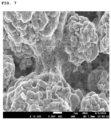
- FIG. 7 is an SEM image taken from an electrode of Comparative Example 3.
- FIG. 8 is an SEM image taken from an electrode of Comparative Example 4.
- the expression “specific surface area” is measured by a Brunauer-Emmett-Teller (BET) method, wherein, specifically, the specific surface area may be calculated from a nitrogen gas adsorption amount at a liquid nitrogen temperature (77K) using BELSORP-mini II by Bell Japan Inc.
- BET Brunauer-Emmett-Teller
- An electrode according to the present invention includes an electrode active material layer, wherein the electrode active material layer includes an electrode active material; polyvinylidene fluoride; and a conductive agent, wherein the conductive agent includes a carbon nanotube structure in which 2 to 5,000 single-walled carbon nanotube units are bonded to each other, and the carbon nanotube structure may be included in an amount of 0.01 wt % to 0.5 wt % in the electrode active material layer.
- the electrode may include an electrode active material layer.
- the electrode may further include a current collector, and, in this case, the electrode active material layer may be disposed on one surface or both surfaces of the current collector.
- the current collector is not particularly limited as long as it has conductivity without causing adverse chemical changes in the battery, and, for example, copper, stainless steel, aluminum, nickel, titanium, alloys thereof, these materials that are surface-treated with one of carbon, nickel, titanium, silver, or the like, or fired carbon may be used.
- the current collector may typically have a thickness of 3 ⁇ m to 500 ⁇ m, and microscopic irregularities may be formed on the surface of the collector to improve the adhesion of a negative electrode active material.
- the electrode collector for example, may be used in various shapes such as that of a film, a sheet, a foil, a net, a porous body, a foam body, a non-woven fabric body, and the like.
- the electrode active material layer may include an electrode active material; polyvinylidene fluoride; and a conductive agent.
- the electrode active material may be a positive electrode active material or negative electrode active material commonly used in the art, but types thereof are not particularly limited.
- the lithium oxide including lithium and at least one metal such as cobalt, manganese, nickel, or aluminum
- the lithium oxide may include lithium-manganese-based oxide (e.g., LiMnO 2 , LiMn 2 O 4 , etc.), lithium-cobalt-based oxide (e.g., LiCoO 2 , etc.), lithium-nickel-based oxide (e.g., LiNiO 2 , etc.), lithium-nickel-manganese-based oxide (e.g., LiNi 1 ⁇ Y1 Mn Y1 O 2 (where 0 ⁇ Y1 ⁇ 1), LiMn 2 ⁇ Z1 Ni z1 O 4 (where 0 ⁇ Z1 ⁇ 2), etc.), lithium-nickel-cobalt-based oxide (e.g., LiNi 1 ⁇ Y2 Co Y2 O 2 (where 0 ⁇ Y2 ⁇ 1), lithium-manganese-cobalt-based oxide (e.g.
- the negative electrode active material may include a carbonaceous material such as artificial graphite, natural graphite, graphitized carbon fibers, and amorphous carbon; a metallic compound alloyable with lithium such as silicon (Si), aluminum (Al), tin (Sn), lead (Pb), zinc (Zn), bismuth (Bi), indium (In), magnesium (Mg), gallium (Ga), cadmium (Cd), a Si alloy, a Sn alloy, or an Al alloy; a metal oxide which may be doped and undoped with lithium such as SiO v (0 ⁇ v ⁇ 2), SnO 2 , vanadium oxide, and lithium vanadium oxide; or a composite including the metallic compound and the carbonaceous material such as a Si—C composite or a Sn—C composite, and any one thereof or a mixture of two or more thereof may be used.
- a metallic lithium thin film may be used as the negative electrode active material.
- both low crystalline carbon and high crystalline carbon may be used as the
- the above-described electrode active material may be included in an amount of 70 wt % to 99.5 wt %, for example, 80 wt % to 99 wt % based on a total weight of the electrode active material layer.
- amount of the electrode active material satisfies the above range, excellent energy density, electrode adhesion, and electrical conductivity may be achieved.
- the conductive agent may include a carbon nanotube structure.
- the carbon nanotube structure may include a plurality of single-walled carbon nanotube units.
- the carbon nanotube structure may be a carbon nanotube structure in which 2 to 5,000 single-walled carbon nanotube units are bonded to each other, and, more specifically, the carbon nanotube structure may be a carbon nanotube structure in which 2 to 4,500 single-walled carbon nanotube units are bonded to each other. More specifically, in consideration of dispersibility of the carbon nanotube structure and durability of the electrode, the carbon nanotube structure is most preferably a carbon nanotube structure in which 2 to 50 single-walled carbon nanotube units are bonded to each other.
- the single-walled carbon nanotube units may be arranged side by side and bonded in the carbon nanotube structure (cylindrical structure having flexibility in which the units are bonded such that long axes of the units are parallel to each other) to form the carbon nanotube structure.
- the carbon nanotube structures are interconnected in the electrode to form a network structure.
- Typical electrodes including carbon nanotubes are generally prepared by preparing a conductive agent dispersion by dispersing bundle type or entangled type carbon nanotubes (form in which single-walled carbon nanotube units or multi-walled carbon nanotube units are attached or entangled with each other) in a dispersion medium and then using the conductive dispersion.
- the carbon nanotubes are fully dispersed in the typical conductive agent dispersion, the carbon nanotubes are present as the conductive agent dispersion in which single-stranded carbon nanotube units are dispersed.
- the typical conductive agent dispersion since the carbon nanotube units are easily cut by an excessive dispersion process, the carbon nanotube units have a length shorter than an initial length.
- the carbon nanotube units may also be easily cut during a rolling process of the electrode, and the carbon nanotube unit may additionally be cut due to changes in volume of the electrode active material during operation of the battery. Accordingly, since conductivity of the electrode is reduced, input characteristics, output characteristics, and life characteristics of the battery may be degraded. Furthermore, with respect to the multi-walled carbon nanotube units, structural defects are high due to a mechanism in which nodes grow (the units are not smooth and linear, but the nodes are present due to defects generated during the growth process). Thus, the multi-walled carbon nanotube units are more easily cut in the dispersion process, and the short-cut multi-walled carbon nanotube units may be easily aggregated by n-n stacking caused by carbon of the unit. Accordingly, it is more difficult for the multi-walled carbon nanotube units to be more uniformly dispersed in an electrode slurry.
- the carbon nanotube structure included in the electrode of the present invention since the carbon nanotube structure is in the form in which 2 to 5,000 single-walled carbon nanotube units maintaining relatively high crystallinity without structural defects are bonded together side by side, the single-walled carbon nanotube units may not be cut even during the operation of the battery and their length may be smoothly maintained. Thus, the conductivity of the electrode may be maintained. Also, since the conductivity of the electrode is increased due to high conductivity of the single-walled carbon nanotube unit having high crystallinity, the input characteristics, output characteristics, and life characteristics of the battery may be significantly improved.
- the carbon nanotube structures are interconnected in the electrode to have a network structure, an excessive change in the volume of the electrode active material may be suppressed, a strong conductive path may be secured at the same time, and electrode adhesion may be significantly improved by inhibiting deintercalation of the electrode active material.
- the single-walled carbon nanotube unit may have an average diameter of 0.5 nm to 10 nm, particularly 1 nm to 9 nm, and more particularly 1 nm to 6 nm.
- the average diameter corresponds to an average value of top 100 single-walled carbon nanotubes with a larger average diameter and bottom 100 single-walled carbon nanotubes when the prepared electrode is observed by a transmission electron microscope (TEM).
- TEM transmission electron microscope
- the single-walled carbon nanotube unit may have an average length of 1 ⁇ m to 100 ⁇ m, for example, 5 ⁇ m to 50 ⁇ m.
- the average length corresponds to an average value of top 100 single-walled carbon nanotubes with a larger average length and bottom 100 single-walled carbon nanotubes when the prepared electrode is observed by a TEM.
- the single-walled carbon nanotube unit may have a specific surface area of 500 m 2 /g to 1,000 m 2 /g, for example, 600 m 2 /g to 800 m 2 /g.
- the specific surface area of the single-walled carbon nanotube unit may specifically be calculated from a nitrogen gas adsorption amount at a liquid nitrogen temperature (77K) using BELSORP-mini II by Bell Japan Inc.
- the carbon nanotube structure may have an average diameter of 1 nm to 300 nm, for example, 3 nm to 150 nm.
- the average diameter corresponds to an average value of diameters of top 100 single-walled carbon nanotubes with a larger average diameter and bottom 100 single-walled carbon nanotubes when the prepared electrode is observed by a scanning electron microscope (SEM).
- the carbon nanotube structure may have an average length of 1 ⁇ m to 100 ⁇ m, for example, 5 ⁇ m to 50 ⁇ m.
- the average length corresponds to an average value of lengths of top 100 single-walled carbon nanotubes with a larger average length and bottom 100 single-walled carbon nanotubes when the prepared electrode is observed by an SEM.
- the carbon nanotube structure may be included in an amount of 0.01 wt % to 0.5 wt % in the electrode active material layer, and may specifically be included in an amount of 0.02 wt % to 0.2 wt %.
- the amount of the carbon nanotube structure satisfies the above range, since the conductive path in the electrode may be secured, the life characteristics of the battery may be improved while electrode resistance is maintained at a low level.
- the carbon nanotube structure is not generated, or is generated in a very small amount (for example, 0.0005 wt %) even if it is unintentionally generated. That is, the above amount range may never be achieved in the usual way.
- an electrode includes a multi-walled carbon nanotube unit
- a large amount (for example, greater than 0.5 wt %) of the multi-walled carbon nanotube unit has to be used to compensate for low conductivity of the multi-walled carbon nanotube unit.
- an electrode is prepared by using a conductive agent dispersion in which single-walled carbon nanotube units are fully dispersed, a small amount of the single-walled carbon nanotube units may not be used due to a limitation where the single-walled carbon nanotube units are cut.
- the carbon nanotube structure included in the electrode of the present invention is in the form in which 2 to 5,000 single-walled carbon nanotube units are bonded together side by side.
- the conductivity of the electrode may be maintained and the conductivity of the electrode may be smoothly secured due to the high conductivity of the single-walled carbon nanotube unit. Accordingly, the input characteristics, output characteristics, and life characteristics of the battery may be excellent even if the amount of the carbon nanotube structure in the electrode is low.
- the single-walled carbon nanotube unit may be surface-treated through an oxidation treatment or nitridation treatment to improve affinity of polyvinylidene fluoride.
- the polyvinylidene fluoride may be a substance that starts to be included in the electrode from the conductive agent dispersion necessary for the preparation of the electrode slurry (in some cases, the polyvinylidene fluoride may be further added to reinforce a binder function during the preparation of the electrode slurry).
- the polyvinylidene fluoride helps to facilitate the dispersion of the bundle-type carbon nanotubes in the conductive agent dispersion.
- the polyvinylidene fluoride may have a weight-average molecular weight of 10,000 g/mol to 1,000,000 g/mol, for example, 100,000 g/mol to 900,000 g/mol.
- the weight-average molecular weight satisfies the above range, since the polyvinylidene fluoride may easily penetrate between the single-walled carbon nanotube units in the bundle type carbon nanotubes, the bundle type carbon nanotubes may be appropriately dispersed and phase stability of the conductive agent dispersion may be improved.
- the polyvinylidene fluoride may be included in an amount of 0.1 wt % to 10.0 wt %, particularly 0.2 wt % to 5.0 wt %, and more particularly 0.2 wt % to 2.5 wt % in the electrode active material layer.
- the amount of the polyvinylidene fluoride satisfies the above range, the carbon nanotube structures are uniformly dispersed, energy density of the electrode is high, and the electrode adhesion may be excellent.
- the polyvinylidene fluoride may include modified polyvinylidene fluoride which is modified with a hydrophilic functional group to improve affinity with the single-walled carbon nanotube unit.
- the polyvinylidene fluoride may include modified polyvinylidene fluoride including at least one functional group selected from an acid functional group and an ester functional group.
- the functional groups of the modified polyvinylidene fluoride may interact with the single-walled carbon nanotube unit to further improve the electrode adhesion while improving the dispersibility of the carbon nanotube structure.
- the functional group may be included in an amount of 0.1 wt % to 5 wt %, for example, 0.3 wt % to 3 wt % in the modified polyvinylidene fluoride.
- the electrode adhesion may be further improved while further improving the dispersibility of the carbon nanotube structure.
- the modified polyvinylidene fluoride may be included in an amount of 1 wt % to 100 wt %, particularly 1 wt % to 50 wt %, and more particularly 1 wt % to 20 wt % based on a total weight of the polyvinylidene fluoride.
- the electrode adhesion may be further improved while further increasing the dispersibility of the carbon nanotube structure.
- the electrode active material layer may further include a binder.
- the binder is for securing adhesion between the electrode active materials and adhesion of the electrode active material to the current collector, wherein common binders used in the art may be used, and types thereof are not particularly limited.
- the binder may include polyvinylidene fluoride-hexafluoropropylene copolymer (PVDF-co-HFP), polyvinyl alcohol, polyacrylonitrile, carboxymethyl cellulose (CMC), starch, hydroxypropyl cellulose, regenerated cellulose, polyvinylpyrrolidone, tetrafluoroethylene, polyethylene, polypropylene, an ethylene-propylene-diene monomer (EPDM), a sulfonated-EPDM, a styrene-butadiene rubber (SBR), a fluorine rubber, or copolymers thereof, and any one thereof or a mixture of two or more thereof may be used.
- PVDF-co-HFP polyvinylidene fluoride-hexafluoropropylene copolymer
- CMC carboxymethyl cellulose
- SBR styrene-butadiene rubber
- the binder may be included in an amount of 10 wt % or less, for example, 0.1 wt % to 5 wt % based on the total weight of the electrode active material layer. In a case in which the amount of the binder satisfies the above range, excellent electrode adhesion may be achieved while minimizing an increase in the electrode resistance.
- the electrode of the present invention configured as described above has excellent electrode adhesion.
- the electrode according to the present invention may have an adhesion measured by a 90° peel test of 20.2 gf/20 mm or more, for example, 21 gf/20 mm or more.
- the method of preparing the electrode of the present invention includes the steps of: (1) preparing a mixture by adding bundle type single-walled carbon nanotubes and polyvinylidene fluoride to a dispersion medium; (2) preparing a conductive agent dispersion including a carbon nanotube structure, in which 2 to 5,000 single-walled carbon nanotube units are bonded to each other, by sonication of the mixture; and (3) forming an electrode slurry including the conductive agent dispersion and an electrode active material, wherein the carbon nanotube structure is included in an amount of 0.01 wt % to 0.5 wt % in a solid content of the electrode slurry.
- the electrode of the above-described embodiment may be prepared by the above method.
- the mixture may be prepared by adding bundle type carbon nanotubes and polyvinylidene fluoride to a dispersion medium.
- the bundle type carbon nanotubes are present in the form of a bundle in which the above-described single-walled carbon nanotube units are bonded, wherein the bundle type carbon nanotube includes usually 2 or more, substantially 500 or more, for example, 5,000 or more single-walled carbon nanotube units.
- the bundle type single-walled carbon nanotubes may be included in an amount of 0.1 wt % to 1.0 wt %, for example, 0.2 wt % to 0.5 wt % in the mixture.
- amount of the bundle type single-walled carbon nanotubes satisfies the above range, since the bundle type single-walled carbon nanotubes are dispersed in an appropriate level, a carbon nanotube structure may be formed at an appropriate level and dispersion stability may be improved.
- the polyvinylidene fluoride may be included in an amount of 0.1 wt % to 20 wt %, for example, 1 wt % to 10 wt % in the mixture.
- the amount of the polyvinylidene fluoride satisfies the above range, since the bundle type single-walled carbon nanotubes are dispersed in an appropriate level, a carbon nanotube structure may be formed at an appropriate level and the dispersion stability may be improved.
- polyvinylidene fluoride is the same as the polyvinylidene fluoride of the above-described embodiment, a description thereof will be omitted.
- a weight ratio of the bundle type carbon nanotubes to the polyvinylidene fluoride may be in a range of 1:0.1 to 1:10, for example, 1:1 to 1:10.
- the weight ratio satisfies the above range, since the bundle type single-walled carbon nanotubes are dispersed in an appropriate level, a carbon nanotube structure may be formed at an appropriate level and the dispersion stability may be improved.
- the dispersion medium may include an amide-based polar organic solvent such as dimethylformamide (DMF), diethylformamide, dimethylacetamide (DMAc), and N-methylpyrrolidone (NMP); alcohols such as methanol, ethanol, 1-propanol, 2-propanol (isopropyl alcohol), 1-butanol (n-butanol), 2-methyl-1-propanol (isobutanol), 2-butanol (sec-butanol), 2-methyl-2-propanol (tert-butanol), pentanol, hexanol, heptanol, or octanol; glycols such as ethylene glycol, diethylene glycol, triethylene glycol, propylene glycol, 1,3-propanediol, 1,3-butanediol, 1,5-pentanediol, or hexylene glycol; polyhydric alcohols such as g
- a solid content in the mixture may be in a range of 0.1 wt % to 20 wt %, for example, 1 wt % to 10 wt %.
- the solid content in the mixture satisfies the above range, since the bundle type single-walled carbon nanotubes are dispersed in an appropriate level, a carbon nanotube structure may be formed at an appropriate level and the dispersion stability may be improved.
- the electrode slurry may have viscosity and elasticity suitable for an electrode preparation process, and it also contributes to increase the solid content of the electrode slurry.
- a process of dispersing the bundle type carbon nanotubes in the mixture may be performed by sonication and using a mixing device such as a homogenizer, a bead mill, a ball mill, a basket mill, an attrition mill, a universal stirrer, a clear mixer, a spike mill, or a TK mixer.
- a mixing device such as a homogenizer, a bead mill, a ball mill, a basket mill, an attrition mill, a universal stirrer, a clear mixer, a spike mill, or a TK mixer.
- the sonication is preferable.
- numerous vacuum bubbles are created by extreme vibration when high-intensity ultrasonic waves are released into a solution, and these bubbles instantaneously clump together or grow, but the bubbles are violently broken in a chainwise manner by immediately following vibration.
- the bundle type carbon nanotubes may be debundled by shock wave energy.
- the sonication enables nanoscale fine dispersion of the single-walled carbon nanotubes in the bundle type carbon nanotube without cutting in a longitudinal direction thereof. For this reason, the sonication is preferable.
- the sonication may be as follows.
- a solid in the mixture may be dispersed by applying ultrasonic waves to the mixture.
- conditions under which the sonication is performed are as follows.
- the sonication may be performed at a power of 800 W to 1,500 W, and may specifically be performed at a power of 800 W to 1,200 W.
- the sonication may be performed for 0.5 hours to 5 hours, and may specifically be performed for 1 hour to 3 hours.
- the bundle type carbon nanotubes may be appropriately separated to form the carbon nanotube structure.
- the performance time means total time during which the sonication is used, and, thus, for example, if the sonication is performed several times, the performance time means total time required for performing the sonication several times.
- the above conditions are for forming the carbon nanotube structure in which 2 to 5,000 single-walled carbon nanotube units are bonded together side by side in the conductive agent dispersion prepared by appropriately dispersing the bundle type carbon nanotubes. This may be achieved only when a composition of the mixture and sonication conditions are strictly controlled.
- the conductive agent dispersion is prepared through the above-described process, the conductive agent dispersion is mixed with an electrode active material to form an electrode slurry.
- the above-described electrode active materials may be used as the electrode active material.
- a binder and a solvent may be further included in the electrode slurry, if necessary.
- the binder of the above-described embodiment may be used as the binder.
- the solvent may include an amide-based polar organic solvent such as dimethylformamide (DMF), diethylformamide, dimethylacetamide (DMAc), and N-methylpyrrolidone (NMP); alcohols such as methanol, ethanol, 1-propanol, 2-propanol (isopropyl alcohol), 1-butanol (n-butanol), 2-methyl-1-propanol (isobutanol), 2-butanol (sec-butanol), 2-methyl-2-propanol (tert-butanol), pentanol, hexanol, heptanol, or octanol; glycols such as ethylene glycol, diethylene glycol, triethylene glycol, propylene glycol, 1,3-propaned
- the electrode active material may be included in an amount of 70 wt % to 99.5 wt %, for example, 80 wt % to 99 wt % based on a total solid content in the electrode slurry.
- the amount of the electrode active material satisfies the above range, excellent energy density, electrode adhesion, and electrical conductivity may be achieved.
- the binder may be included in an amount of 10 wt % or less, for example, 0.1 wt % to 5 wt % based on the total solid content in the electrode slurry.
- a solid content in the electrode slurry may be in a range of 60 wt % to 80 wt %, for example, 65 wt % to 75 wt %.
- the solid content in the electrode slurry satisfies the above range, migration of the conductive agent and the binder caused by the evaporation of the solvent may be suppressed during drying after coating of the electrode slurry, and an electrode having excellent electrode adhesion and electrical conductivity may be prepared.
- a high-quality electrode having less deformation of the electrode during rolling may be prepared.
- the carbon nanotube structure may be included in an amount of 0.01 wt % to 0.5 wt % in the solid content of the electrode slurry, and may specifically be included in an amount of 0.02 wt % to 0.2 wt %.
- the amount of the carbon nanotube structure satisfies the above range, since the conductive path in the electrode may be secured, the life characteristics of the battery may be improved while the electrode resistance is maintained at a low level.
- the electrode slurry prepared as described above is coated and dried to form an electrode active material layer.
- the electrode active material layer may be prepared by a method of coating the electrode slurry on an electrode collector and drying the coated electrode collector, or may be prepared by a method of casting the electrode slurry on a separate support and then laminating a film separated from the support on the electrode collector. If necessary, the electrode active material layer is formed by the above-described method, and a rolling process may then be further performed.
- drying and the rolling may be performed under appropriate conditions in consideration of physical properties of the electrode to be finally prepared, and are not particularly limited.
- the secondary battery according to the present invention includes the above-described electrode of the present invention.
- the electrode may be at least one of a positive electrode and a negative electrode.
- the secondary battery according to the present invention may include a positive electrode, a negative electrode, a separator disposed between the positive electrode and the negative electrode, and an electrolyte, and, in this case, at least one of the positive electrode and the negative electrode may be the above-described electrode of the present invention, that is, the electrode which includes the electrode active material layer including the electrode active material and the carbon nanotube structure.
- the electrode of the present invention may be the positive electrode. Since the electrode according to the present invention has been described above, a detailed description thereof will be omitted, and hereinafter, only the other components will be described.
- the separator separates the negative electrode and the positive electrode and provides a movement path of lithium ions, wherein any separator may be used as the separator without particular limitation as long as it is typically used in a lithium secondary battery.
- a porous polymer film for example, a porous polymer film prepared from a polyolefin-based polymer, such as an ethylene homopolymer, a propylene homopolymer, an ethylene/butene copolymer, an ethylene/hexene copolymer, and an ethylene/methacrylate copolymer, or a laminated structure having two or more layers thereof may be used as the separator.
- a typical porous nonwoven fabric for example, a nonwoven fabric formed of high melting point glass fibers or polyethylene terephthalate fibers may be used.
- a coated separator including a ceramic component or a polymer material may be used to secure heat resistance or mechanical strength, and the separator having a single layer or multilayer structure may be selectively used.
- the electrolyte may include an organic liquid electrolyte, an inorganic liquid electrolyte, a solid polymer electrolyte, a gel-type polymer electrolyte, a solid inorganic electrolyte, or a molten-type inorganic electrolyte which may be used in the preparation of the lithium secondary battery, but the present invention is not limited thereto.
- the electrolyte may include a non-aqueous organic solvent and a metal salt.
- an aprotic solvent such as N-methyl-2-pyrrolidone, propylene carbonate, ethylene carbonate, butylene carbonate, dimethyl carbonate, diethyl carbonate, ⁇ -butyrolactone, 1,2-dimethoxy ethane, tetrahydrofuran, 2-methyl tetrahydrofuran, dimethyl sulfoxide, 1,3-dioxolane, formamide, diemthylformamide, dioxolane, acetonitrile, nitromethane, methyl formate, methyl acetate, phosphate triester, trimethoxy methane, a dioxolane derivative, sulfolane, methyl sulfolane, 1,3-dimethyl-2-imidazolidinone, a propylene carbonate derivative, a tetrahydrofuran derivative, ether, methyl propionate, and ethyl propionate
- N-methyl-2-pyrrolidone prop
- the cyclic carbonate since ethylene carbonate and propylene carbonate, as cyclic carbonate, well dissociate a lithium salt due to high permittivity as a highly viscous organic solvent, the cyclic carbonate may be preferably used. Since an electrolyte having high electrical conductivity may be prepared when the above cyclic carbonate is mixed with low viscosity, low permittivity linear carbonate, such as dimethyl carbonate and diethyl carbonate, in an appropriate ratio and used, the cyclic carbonate may be more preferably used.
- a lithium salt may be used as the metal salt, and the lithium salt is a material that is readily soluble in the non-aqueous organic solvent, wherein, for example, at least one selected from the group consisting of F ⁇ , Cl ⁇ , I ⁇ , NO 3 ⁇ , N(CN) 2 ⁇ , BF 4 ⁇ , ClO 4 ⁇ , PF 6 ⁇ , (CF 3 ) 2 PF 4 ⁇ , (CF 3 ) 3 PF 3 ⁇ , (CF 3 ) 4 PF 2 ⁇ , (CF 3 ) 5 PF ⁇ , (CF 3 ) 6 P ⁇ , CF 3 SO 3 ⁇ , CF 3 CF 2 SO 3 ⁇ , (CF 3 SO 2 ) 2 N ⁇ (FSO 2 ) 2 N ⁇ , CF 3 CF 2 (CF 3 ) 2 CO ⁇ , (CF 3 SO 2 ) 2 CH ⁇ , (SF 5 ) 3 C ⁇ , (CF 3 SO 2
- At least one additive for example, a halo-alkylene carbonate-based compound such as difluoroethylene carbonate, pyridine, triethylphosphite, triethanolamine, cyclic ether, ethylenediamine, n-glyme, hexaphosphoric triamide, a nitrobenzene derivative, sulfur, a quinone imine dye, N-substituted oxazolidinone, N,N-substituted imidazolidine, ethylene glycol dialkyl ether, an ammonium salt, pyrrole, 2-methoxy ethanol, or aluminum trichloride, may be further added to the electrolyte in addition to the electrolyte components.
- a halo-alkylene carbonate-based compound such as difluoroethylene carbonate, pyridine, triethylphosphite, triethanolamine, cyclic ether, ethylenediamine, n-glyme, hexaphosphoric
- the secondary battery according to the present invention as described above has excellent electrode adhesion in comparison to a conventional secondary battery, and has excellent life characteristics at a high temperature.
- bundle type carbon nanotubes (specific surface area of 650 m 2 /g) composed of single-walled carbon nanotube units having an average diameter of 1.5 nm and an average length of 5 ⁇ m and 2.0 parts by weight of polyvinylidene fluoride (weight-average molecular weight: 685,000 g/mol, standard homo-polymer) were mixed in 97.8 parts by weight of N-methylpyrrolidone (NMP), as a dispersion medium, to prepare a mixture such that a solid content was 2.2 wt %.
- NMP N-methylpyrrolidone
- the bundle type carbon nanotubes were dispersed in the dispersion medium by stirring the mixture by sonication and thus, a conductive agent dispersion was prepared. In this case, the sonication was performed at a power of 1,000 W for 1.5 hours.
- the conductive agent dispersion included a carbon nanotube structure in the form in which 2 to 5,000 single-walled carbon nanotube units were bonded together side by side. In the conductive agent dispersion, an amount of the carbon nanotube structure was 0.2 wt %, and an amount of the polyvinylidene fluoride was 2.0 wt %.
- a conductive agent dispersion was prepared in the same manner as in Preparation Example 1 except that the polyvinylidene fluoride was modified polyvinylidene fluoride (weight-average molecular weight: 880,000 g/mol) including an acid functional group in an amount of 2.1 wt %.
- bundle type carbon nanotubes (specific surface area of 185 m 2 /g) composed of multi-walled carbon nanotube units having an average diameter of 10 nm and an average length of 1 ⁇ m and 0.8 part by weight of modified polyvinylidene fluoride (weight-average molecular weight: 880,000 g/mol) including an acid functional group in an amount of 2.1 wt % were mixed in 95.2 parts by weight of N-methylpyrrolidone (NMP), as a dispersion medium, to prepare a mixture such that a solid content was 4.8 wt %.
- NMP N-methylpyrrolidone
- the bundle type carbon nanotubes were dispersed in the dispersion medium by stirring the mixture by sonication and thus, a conductive agent dispersion was prepared.
- the sonication was performed at a power of 1,000 W for 1.5 hours.
- an amount of the multi-walled carbon nanotube units was 4.0 wt %
- an amount of the polyvinylidene fluoride was 0.8 wt %.
- bundle type carbon nanotubes (specific surface area of 650 m 2 /g) composed of single-walled carbon nanotube units having an average diameter of 1.5 nm and an average length of 5 ⁇ m and 4.0 parts by weight of polyvinylidene fluoride (weight-average molecular weight: 220,000 g/mol, standard homo-polymer) were mixed in 95.8 parts by weight of N-methylpyrrolidone (NMP), as a dispersion medium, to prepare a mixture such that a solid content was 4.2 wt %.
- NMP N-methylpyrrolidone
- the bundle type carbon nanotubes were dispersed in the dispersion medium by stirring the mixture by sonication and thus, a conductive agent dispersion was prepared.
- the sonication was performed at a power of 2,000 W for 5 hours.
- an amount of the bundle type carbon nanotubes was 0.2 wt %, and an amount of the polyvinylidene fluoride was 4.0 wt %.
- LiNi 0.6 Co 0.2 Mn 0.2 O 2 (NCM622) and modified polyvinylidene fluoride (modified PVDF, KF9700, weight-average molecular weight: 880,000 g/mol, 2.1 wt % of acid functional group was included) were added to the conductive agent dispersion of Preparation Example 1, and N-methylpyrrolidone (NMP) was further added thereto to prepare a positive electrode slurry in which a solid content was 70.1 wt %.
- the positive electrode slurry was coated on a 20 ⁇ m thick aluminum (Al) thin film current collector, dried at 130° C., and then rolled to prepare a positive electrode including a positive electrode active material layer.
- a positive electrode was prepared in the same manner as in Example 1 except that the conductive agent dispersion of Preparation Example 2 was used instead of the conductive agent dispersion of Preparation Example 1. All the polyvinylidene fluoride included in the positive electrode was modified polyvinylidene fluoride.
- LiNi 0.6 Co 0.2 Mn 0.2 O 2 (NCM622) and modified polyvinylidene fluoride (modified PVDF, KF9700, weight-average molecular weight: 880,000 g/mol, 2.1 wt % of acid functional group was included) were added to the conductive agent dispersion of Preparation Example 2, and N-methylpyrrolidone (NMP) was further added thereto to prepare a positive electrode slurry in which a solid content was 70.1 wt %.
- the positive electrode slurry was coated on a 20 ⁇ m thick Al thin film current collector, dried at 130° C., and then rolled to prepare a positive electrode including a positive electrode active material layer.
- Carbon black having a specific surface area of 240 m 2 /g and modified polyvinylidene fluoride (modified PVDF, KF9700, weight-average molecular weight: 880,000 g/mol, 2.1 wt % of acid functional group was included) were mixed in N-methylpyrrolidone (NMP) to prepare a mixture such that a solid content was 72.0 wt %.
- NMP N-methylpyrrolidone
- the carbon black was dispersed in the dispersion medium by stirring the mixture by sonication and thus, a conductive agent dispersion was prepared. In this case, the sonication was performed at a power of 1,000 W for 1.5 hours.
- the conductive agent dispersion an amount of the carbon black was 15 wt %, and an amount of the modified polyvinylidene fluoride was 1.5 wt %.
- LiNi 0.6 Co 0.2 Mn 0.2 O 2 (NCM622) and modified polyvinylidene fluoride (modified PVDF, KF9700, weight-average molecular weight: 880,000 g/mol, 2.1 wt % of acid functional group was included) were added to the conductive agent dispersion, and N-methylpyrrolidone (NMP) was further added thereto to prepare a positive electrode slurry in which a solid content was 72.0 wt %.
- the positive electrode slurry was coated on a 20 ⁇ m thick Al thin film current collector, dried at 130° C., and then rolled to prepare a positive electrode including a positive electrode active material layer.
- LiNi 0.6 Co 0.2 Mn 0.2 O 2 (NCM622) and modified polyvinylidene fluoride (modified PVDF, KF9700, weight-average molecular weight: 880,000 g/mol, 2.1 wt % of acid functional group was included) were added to the conductive agent dispersion of Preparation Example 3, and N-methylpyrrolidone (NMP) was further added thereto to prepare a positive electrode slurry in which a solid content was 72.1 wt %.
- the positive electrode slurry was coated on a 20 ⁇ m thick Al thin film current collector, dried at 130° C., and then rolled to prepare a positive electrode including a positive electrode active material layer.
- LiNi 0.6 Co 0.2 Mn 0.2 O 2 (NCM622) and modified polyvinylidene fluoride (modified PVDF, KF9700, weight-average molecular weight: 880,000 g/mol, 2.1 wt % of acid functional group was included) were added to the conductive agent dispersion of Preparation Example 3, and N-methylpyrrolidone (NMP) was further added thereto to prepare a positive electrode slurry in which a solid content was 72.0 wt %.
- the positive electrode slurry was coated on a 20 ⁇ m thick Al thin film current collector, dried at 130° C., and then rolled to prepare a positive electrode including a positive electrode active material layer.
- a positive electrode was prepared in the same manner as in Example 3 except that the conductive agent dispersion of Preparation Example 4 was used instead of the conductive agent dispersion of Preparation Example 2. 97.9 wt % of the LiNi 0.6 Co 0.2 Mn 0.2 O 2 (NCM622), 2.05 wt % of the polyvinylidene fluoride, and 0.05 wt % of the carbon nanotube structure were included in the positive electrode active material layer. An amount of the modified polyvinylidene fluoride was 2.05 wt % based on a total weight of the polyvinylidene fluoride.
- the active material layers of the positive electrodes prepared by Examples 1 to 3 and Comparative Examples 1 to 4 were observed by a scanning electron microscope (SEM). SEM images taken from the electrodes of Examples 1 to 3 (in sequence) are illustrated in FIGS. 2 to 4 , respectively, and SEM images taken from the electrodes of Comparative Examples to 4 (in sequence) are illustrated in FIGS. 5 to 8 , respectively.
- SEM scanning electron microscope
- the positive electrode slurries used in the preparation of the positive electrodes of Examples 1 to 3 and Comparative Examples 1 to 4 were vacuum-dried at a temperature of 130° C. for 3 hours and then ground to prepare powders. Thereafter, pellets were prepared under a load of 9.8 MPa at 25° C. and a relative humidity of 50% using a Loresta GP instrument from Mitsubishi Chem. Analytec. Co., Ltd. Thereafter, powder resistance was measured by a 4-probe method. Measurement results are presented in Table 1 below.
- Adhesion of each of the positive electrodes of Examples 1 to 3 and Comparative Examples 1 to 4 was measured by a 90° peel test method.
- Each of the positive electrodes of Examples 1 to 3 and Comparative Examples 1 to 4, a negative electrode, and a 15 ⁇ m thick polyethylene-based separator were combined to prepare a mono-cell.
- graphite, SBR/CMC, and a conductive agent were mixed in a weight ratio of 96.5:2.5:1 to prepare a negative electrode slurry, and the negative electrode slurry was coated on a 10 ⁇ m thick copper foil and dried at 100° C. to prepare the negative electrode.
Abstract
Description
| TABLE 1 | |||||||
| Comparative | Comparative | Comparative | Comparative | ||||
| Example 1 | Example 2 | Example 3 | Example 1 | Example 2 | Example 3 | Example 4 | |
| Conductive | 650 | 650 | 650 | 240 | 185 | 185 | 650 |
| agent specific | |||||||
| surface area | |||||||
| (m2/g) | |||||||
| Conductive | 0.1 | 0.1 | 0.05 | 1.5 | 0.6 | 0.8 | 0.05 |
| agent amount | (carbon | (carbon | (carbon | (carbon | (multi- | (multi- | (fully |
| (wt %) | nanotube | nanotube | nanotube | black) | walled | walled | dispersed |
| structure) | structure) | structure) | carbon | carbon | carbon | ||
| nanotube | nanotube | nanotube | |||||
| units) | units | units | |||||
| Polyvinylidene | 1.8 | 1.8 | 1.8 | 2.0 | 1.8 | 2.0 | 1.8 |
| fluoride amount | |||||||
| (wt %) | |||||||
| Positive | 70.1 | 70.1 | 70.1 | 72.0 | 72.1 | 72.0 | 70.1 |
| electrode | |||||||
| slurry solid | |||||||
| content (wt %) | |||||||
| Positive | 22,600 | 24,700 | 15,900 | 11,900 | 21,500 | 32,250 | 18,500 |
| electrode | |||||||
| slurry | |||||||
| viscosity (cPs) | |||||||
| Positive | 28.5 | 41.5 | 53.8 | 154.1 | 72.6 | 29.7 | 1,590 |
| electrode | |||||||
| slurry powder | |||||||
| resistance | |||||||
| (Ω · cm) | |||||||
| Positive | 21.6 | 22.8 | 22.4 | 19.8 | 14.2 | 19.1 | 3.2 |
| electrode | |||||||
| adhesion | |||||||
| (gf/20 mm) | |||||||
| Life | 97.5 | 96.9 | 96.4 | 93.7 | 94.6 | 95.3 | 85.6 |
| characteristics | |||||||
| (%) | |||||||
Claims (18)
Applications Claiming Priority (5)
| Application Number | Priority Date | Filing Date | Title |
|---|---|---|---|
| KR20180040574 | 2018-04-06 | ||
| KR10-2018-0040574 | 2018-04-06 | ||
| KR10-2019-0040100 | 2019-04-05 | ||
| KR1020190040100A KR102285981B1 (en) | 2018-04-06 | 2019-04-05 | Electrode, secondary battery comprising the same, and method for preparing the electrode |
| PCT/KR2019/004127 WO2019194662A1 (en) | 2018-04-06 | 2019-04-08 | Electrode, secondary battery comprising same electrode, and method for manufacturing same electrode |
Related Parent Applications (1)
| Application Number | Title | Priority Date | Filing Date |
|---|---|---|---|
| PCT/KR2019/004127 A-371-Of-International WO2019194662A1 (en) | 2018-04-06 | 2019-04-08 | Electrode, secondary battery comprising same electrode, and method for manufacturing same electrode |
Related Child Applications (1)
| Application Number | Title | Priority Date | Filing Date |
|---|---|---|---|
| US18/381,475 Continuation US20240079554A1 (en) | 2018-04-06 | 2023-10-18 | Electrode, Secondary Battery Including the Electrode, and Method of Preparing the Electrode |
Publications (2)
| Publication Number | Publication Date |
|---|---|
| US20210020907A1 US20210020907A1 (en) | 2021-01-21 |
| US11831006B2 true US11831006B2 (en) | 2023-11-28 |
Family
ID=68421277
Family Applications (2)
| Application Number | Title | Priority Date | Filing Date |
|---|---|---|---|
| US17/043,362 Active 2040-05-03 US11831006B2 (en) | 2018-04-06 | 2019-04-08 | Electrode, secondary battery including the electrode, and method of preparing the electrode |
| US18/381,475 Pending US20240079554A1 (en) | 2018-04-06 | 2023-10-18 | Electrode, Secondary Battery Including the Electrode, and Method of Preparing the Electrode |
Family Applications After (1)
| Application Number | Title | Priority Date | Filing Date |
|---|---|---|---|
| US18/381,475 Pending US20240079554A1 (en) | 2018-04-06 | 2023-10-18 | Electrode, Secondary Battery Including the Electrode, and Method of Preparing the Electrode |
Country Status (5)
| Country | Link |
|---|---|
| US (2) | US11831006B2 (en) |
| EP (2) | EP4329032A2 (en) |
| JP (1) | JP7164244B2 (en) |
| KR (1) | KR102285981B1 (en) |
| CN (1) | CN111954949B (en) |
Families Citing this family (17)
| Publication number | Priority date | Publication date | Assignee | Title |
|---|---|---|---|---|
| KR102641907B1 (en) * | 2019-10-04 | 2024-02-29 | 주식회사 엘지에너지솔루션 | Electrode and secondary battery comprising the same |
| KR20210130558A (en) * | 2020-04-22 | 2021-11-01 | 주식회사 엘지에너지솔루션 | Silicon-carbon composite negative electrode material, negative electrode comprising the silicon-carbon composite negative electrode material, and secondary battery comprising the negative electrode |
| KR20210130659A (en) * | 2020-04-22 | 2021-11-01 | 주식회사 엘지화학 | Negative electrode and secondary battery comprising the same |
| WO2022045852A1 (en) | 2020-08-28 | 2022-03-03 | 주식회사 엘지에너지솔루션 | Negative electrode and secondary battery comprising same |
| KR20220031207A (en) * | 2020-09-04 | 2022-03-11 | 주식회사 엘지에너지솔루션 | Separator and secondary battery comprising the same |
| CN115136346A (en) * | 2020-10-23 | 2022-09-30 | 株式会社Lg新能源 | Negative electrode and secondary battery including the same |
| KR20220059928A (en) | 2020-11-03 | 2022-05-10 | 주식회사 나노신소재 | Slurry composition for negative electrode of lithium secondary battery |
| KR20220059927A (en) * | 2020-11-03 | 2022-05-10 | 주식회사 나노신소재 | Slurry composition for positive electrode of lithium secondary battery |
| KR20220092435A (en) * | 2020-12-24 | 2022-07-01 | 주식회사 엘지에너지솔루션 | Positive electrode for lithium secondary battery and lithium secondary battery comprising the same |
| CN115836404A (en) * | 2020-12-28 | 2023-03-21 | 株式会社Lg新能源 | Negative electrode and method for producing same |
| JP2023543588A (en) * | 2021-03-19 | 2023-10-17 | エルジー エナジー ソリューション リミテッド | Electrode and secondary battery including the electrode |
| KR20230047787A (en) | 2021-10-01 | 2023-04-10 | 주식회사 나노신소재 | Slurry composition for positive electrode of lithium secondary battery |
| KR20230149256A (en) | 2022-04-19 | 2023-10-26 | 주식회사 나노신소재 | Slurry composition for positive electrode of lithium secondary battery |
| GB2622037A (en) * | 2022-08-31 | 2024-03-06 | Dyson Technology Ltd | Energy storage devices and components thereof |
| CN116111043B (en) * | 2023-04-11 | 2023-08-22 | 宁德新能源科技有限公司 | Positive electrode sheet, secondary battery, and electronic device |
| CN116093258A (en) * | 2023-04-11 | 2023-05-09 | 宁德新能源科技有限公司 | Positive electrode sheet, secondary battery, and electronic device |
| CN117174905A (en) * | 2023-09-01 | 2023-12-05 | 东阳利维能新能源科技有限公司 | High-conductivity high-capacity positive electrode plate, lithium battery and preparation method of lithium battery |
Citations (34)
| Publication number | Priority date | Publication date | Assignee | Title |
|---|---|---|---|---|
| US20030099883A1 (en) | 2001-10-10 | 2003-05-29 | Rosibel Ochoa | Lithium-ion battery with electrodes including single wall carbon nanotubes |
| KR20070027438A (en) | 2005-09-06 | 2007-03-09 | 주식회사 엘지화학 | Composite binder containing carbon nanotube and lithium secondary battery employing the same |
| US20090181309A1 (en) | 2008-01-15 | 2009-07-16 | Samsung Electronics Co., Ltd. | Electrode, lithium battery, method of manufacturing electrode, and composition for coating electrode |
| JP2010129169A (en) | 2008-11-25 | 2010-06-10 | National Institute Of Advanced Industrial Science & Technology | Carbon nanotube material for negative electrode and lithium ion secondary battery using this as negative electrode |
| WO2012114590A1 (en) | 2011-02-23 | 2012-08-30 | 三洋電機株式会社 | Electrode for non-aqueous electrolyte secondary battery, method for producing same, and non-aqueous electrolyte secondary battery |
| US20130171516A1 (en) * | 2011-12-28 | 2013-07-04 | Hon Hai Precision Industry Co., Ltd. | Lithium ion battery electrode |
| US20130193063A1 (en) | 2010-10-14 | 2013-08-01 | Ying Yuk Ng | Nonwoven fabric, method for producing the same, and filter formed with the same |
| KR20130132550A (en) | 2010-12-21 | 2013-12-04 | 바이엘 인텔렉쳐 프로퍼티 게엠베하 | Method for producing powdery polymer/carbon nanotube mixtures |
| WO2014088070A1 (en) | 2012-12-05 | 2014-06-12 | 日本ゼオン株式会社 | Lithium ion secondary battery |
| KR20140079702A (en) | 2012-12-19 | 2014-06-27 | 삼성에스디아이 주식회사 | Negative electrode for rechargeable lithium battery, method of preparing the same and rechargeable lithium battery including the same |
| US20140248544A1 (en) | 2013-02-07 | 2014-09-04 | Weibing Xing | Metalized, three-dimensional structured oxygen cathode materials for lithium/air batteries and method for making and using the same |
| JP2014203804A (en) | 2013-04-10 | 2014-10-27 | 日本ゼオン株式会社 | Positive electrode for lithium ion secondary battery and lithium ion secondary battery |
| US20140326651A1 (en) | 2011-02-28 | 2014-11-06 | Fairtech Investment Limited | Connector assembly for use in filter elements of press filter and press filter comprising the same |
| JP2015053165A (en) | 2013-09-06 | 2015-03-19 | 日立化成株式会社 | Positive electrode for lithium ion secondary batteries, and lithium ion secondary battery |
| US20150083975A1 (en) | 2013-09-24 | 2015-03-26 | Samsung Sdi Co., Ltd. | Composite binder composition for secondary battery, cathode and lithium battery containing the binder composition |
| WO2015053411A1 (en) | 2013-10-08 | 2015-04-16 | 日本ゼオン株式会社 | Metal composite material and method for producing same |
| JP2015105213A (en) | 2013-11-29 | 2015-06-08 | 日本ゼオン株式会社 | Carbon nanotube and dispersion liquid thereof, and self-supporting film and composite material |
| CN204927432U (en) | 2015-07-03 | 2015-12-30 | 深圳市慧通天下科技股份有限公司 | Cylindrical lithium ion power batteries |
| JP2016048698A (en) | 2016-01-04 | 2016-04-07 | 日立化成株式会社 | Conducting agent for lithium ion secondary battery positive electrode, positive electrode material for lithium ion secondary battery arranged by use thereof, positive electrode mixture for lithium ion secondary battery, positive electrode for lithium ion secondary battery, and lithium ion secondary battery |
| US20160111724A1 (en) | 2013-05-31 | 2016-04-21 | Showa Denko K.K. | Negative electrode material for lithium ion secondary battery |
| KR20160066498A (en) | 2014-12-02 | 2016-06-10 | 주식회사 엘지화학 | Binder for Secondary Battery And Secondary Battery Comprising The Same |
| JP2016190772A (en) | 2015-03-31 | 2016-11-10 | 日本ゼオン株式会社 | Carbon film, and method for producing the same |
| US20170077497A1 (en) | 2015-09-16 | 2017-03-16 | Samsung Electronics Co., Ltd. | Electrode active material, electrode and secondary battery including the same, and method of preparing the electrode active material |
| KR20170037458A (en) | 2015-09-25 | 2017-04-04 | 주식회사 엘지화학 | Carbon nanotube dispersed solution and method for preparing the same |
| JP2017084759A (en) | 2015-10-30 | 2017-05-18 | 大阪瓦斯株式会社 | Electrode active material-carbon nanotube composite and manufacturing method thereof |
| KR20170063402A (en) | 2015-11-30 | 2017-06-08 | 주식회사 엘지화학 | Positive electrode for secondary battery and secondary battery comprising the same |
| KR20170084798A (en) | 2016-01-13 | 2017-07-21 | 주식회사 엘지화학 | Anode Comprising Anode Active Material having Large Specific Surface Area and Method of Manufacturing the Same |
| KR20170098146A (en) | 2016-02-19 | 2017-08-29 | 삼성에스디아이 주식회사 | Positive electrode and wounding element for rechargeable lithium battery, and rechargeable lithium battery |
| CN107104245A (en) | 2017-05-03 | 2017-08-29 | 南京安普瑞斯有限公司 | A kind of lithium ion battery |
| KR20170127240A (en) | 2016-05-11 | 2017-11-21 | 주식회사 엘지화학 | Electrode, method for fabricating the same, and lithium secondary battery comprising the same |
| US20170338468A1 (en) | 2015-01-13 | 2017-11-23 | Lg Chem, Ltd. | Method of preparing composition for forming positive electrode of lithium secondary battery, and positive electrode and lithium secondary battery manufactured by using the composition |
| CN107681157A (en) | 2017-08-08 | 2018-02-09 | 广州鹏辉能源科技股份有限公司 | A kind of lithium ion battery conductive agent and its lithium ion battery |
| KR20180033746A (en) | 2016-09-26 | 2018-04-04 | 울산과학기술원 | Three-dimensional porous-structured electrode, and electrochemical device having the electrode |
| US20180159131A1 (en) * | 2015-06-12 | 2018-06-07 | Lg Chem, Ltd. | Positive electrode material mixture and secondary battery including the same |
-
2019
- 2019-04-05 KR KR1020190040100A patent/KR102285981B1/en active IP Right Grant
- 2019-04-08 JP JP2021502684A patent/JP7164244B2/en active Active
- 2019-04-08 EP EP24151176.5A patent/EP4329032A2/en active Pending
- 2019-04-08 US US17/043,362 patent/US11831006B2/en active Active
- 2019-04-08 CN CN201980024445.4A patent/CN111954949B/en active Active
- 2019-04-08 EP EP19781670.5A patent/EP3761417B1/en active Active
-
2023
- 2023-10-18 US US18/381,475 patent/US20240079554A1/en active Pending
Patent Citations (45)
| Publication number | Priority date | Publication date | Assignee | Title |
|---|---|---|---|---|
| US20030099883A1 (en) | 2001-10-10 | 2003-05-29 | Rosibel Ochoa | Lithium-ion battery with electrodes including single wall carbon nanotubes |
| KR20070027438A (en) | 2005-09-06 | 2007-03-09 | 주식회사 엘지화학 | Composite binder containing carbon nanotube and lithium secondary battery employing the same |
| US20070202403A1 (en) | 2005-09-06 | 2007-08-30 | Eun-Suok Oh | Composite binder containing carbon nanotube and lithium secondary battery employing the same |
| US20090181309A1 (en) | 2008-01-15 | 2009-07-16 | Samsung Electronics Co., Ltd. | Electrode, lithium battery, method of manufacturing electrode, and composition for coating electrode |
| KR20090078656A (en) | 2008-01-15 | 2009-07-20 | 삼성전자주식회사 | Electrode, lithium battery, method for preparing electrode and composition for electrode coating |
| JP2010129169A (en) | 2008-11-25 | 2010-06-10 | National Institute Of Advanced Industrial Science & Technology | Carbon nanotube material for negative electrode and lithium ion secondary battery using this as negative electrode |
| JP2017008475A (en) | 2010-10-14 | 2017-01-12 | フェアテック インヴェストメント リミテッド | Needle-punch felt fabric of nonwoven fabric, method for producing the same, and filter made by using the same |
| US20130193063A1 (en) | 2010-10-14 | 2013-08-01 | Ying Yuk Ng | Nonwoven fabric, method for producing the same, and filter formed with the same |
| KR20130132550A (en) | 2010-12-21 | 2013-12-04 | 바이엘 인텔렉쳐 프로퍼티 게엠베하 | Method for producing powdery polymer/carbon nanotube mixtures |
| US20140001416A1 (en) | 2010-12-21 | 2014-01-02 | Bayer Intellectual Property Gmbh | Method for producing powdery polymer/carbon nanotube mixtures |
| WO2012114590A1 (en) | 2011-02-23 | 2012-08-30 | 三洋電機株式会社 | Electrode for non-aqueous electrolyte secondary battery, method for producing same, and non-aqueous electrolyte secondary battery |
| US20130313486A1 (en) | 2011-02-23 | 2013-11-28 | Sanyo Electric Co., Ltd. | Electrode for non-aqueous electrolyte secondary battery, method for producing same, and non-aqueous electrolyte secondary battery |
| US20140326651A1 (en) | 2011-02-28 | 2014-11-06 | Fairtech Investment Limited | Connector assembly for use in filter elements of press filter and press filter comprising the same |
| US20150218740A1 (en) | 2011-12-21 | 2015-08-06 | Fairtech Investment Limited | Needle-punched non-woven fabric, manufacturing method thereof and filter and sound absorbing material formed thereby |
| US20130171516A1 (en) * | 2011-12-28 | 2013-07-04 | Hon Hai Precision Industry Co., Ltd. | Lithium ion battery electrode |
| WO2014088070A1 (en) | 2012-12-05 | 2014-06-12 | 日本ゼオン株式会社 | Lithium ion secondary battery |
| KR20140079702A (en) | 2012-12-19 | 2014-06-27 | 삼성에스디아이 주식회사 | Negative electrode for rechargeable lithium battery, method of preparing the same and rechargeable lithium battery including the same |
| US20140248544A1 (en) | 2013-02-07 | 2014-09-04 | Weibing Xing | Metalized, three-dimensional structured oxygen cathode materials for lithium/air batteries and method for making and using the same |
| JP2014203804A (en) | 2013-04-10 | 2014-10-27 | 日本ゼオン株式会社 | Positive electrode for lithium ion secondary battery and lithium ion secondary battery |
| US20160111724A1 (en) | 2013-05-31 | 2016-04-21 | Showa Denko K.K. | Negative electrode material for lithium ion secondary battery |
| KR20170118968A (en) | 2013-05-31 | 2017-10-25 | 쇼와 덴코 가부시키가이샤 | Negative electrode material for lithium ion secondary battery |
| JP2015053165A (en) | 2013-09-06 | 2015-03-19 | 日立化成株式会社 | Positive electrode for lithium ion secondary batteries, and lithium ion secondary battery |
| US20150083975A1 (en) | 2013-09-24 | 2015-03-26 | Samsung Sdi Co., Ltd. | Composite binder composition for secondary battery, cathode and lithium battery containing the binder composition |
| KR20150033439A (en) | 2013-09-24 | 2015-04-01 | 삼성에스디아이 주식회사 | Composite binder composition for secondary battery, cathode and lithium battery containing the binder |
| WO2015053411A1 (en) | 2013-10-08 | 2015-04-16 | 日本ゼオン株式会社 | Metal composite material and method for producing same |
| JP2015105213A (en) | 2013-11-29 | 2015-06-08 | 日本ゼオン株式会社 | Carbon nanotube and dispersion liquid thereof, and self-supporting film and composite material |
| KR20160066498A (en) | 2014-12-02 | 2016-06-10 | 주식회사 엘지화학 | Binder for Secondary Battery And Secondary Battery Comprising The Same |
| US20170338468A1 (en) | 2015-01-13 | 2017-11-23 | Lg Chem, Ltd. | Method of preparing composition for forming positive electrode of lithium secondary battery, and positive electrode and lithium secondary battery manufactured by using the composition |
| JP2016190772A (en) | 2015-03-31 | 2016-11-10 | 日本ゼオン株式会社 | Carbon film, and method for producing the same |
| US20180159131A1 (en) * | 2015-06-12 | 2018-06-07 | Lg Chem, Ltd. | Positive electrode material mixture and secondary battery including the same |
| CN204927432U (en) | 2015-07-03 | 2015-12-30 | 深圳市慧通天下科技股份有限公司 | Cylindrical lithium ion power batteries |
| US20170077497A1 (en) | 2015-09-16 | 2017-03-16 | Samsung Electronics Co., Ltd. | Electrode active material, electrode and secondary battery including the same, and method of preparing the electrode active material |
| KR20170033123A (en) | 2015-09-16 | 2017-03-24 | 삼성전자주식회사 | Electrode active material, electrode and secondary battery including the same, and method of preparing the electrode active material |
| US20180269485A1 (en) | 2015-09-25 | 2018-09-20 | Lg Chem, Ltd. | Carbon nanotube dispersion and method for producing same |
| KR20170037458A (en) | 2015-09-25 | 2017-04-04 | 주식회사 엘지화학 | Carbon nanotube dispersed solution and method for preparing the same |
| JP2017084759A (en) | 2015-10-30 | 2017-05-18 | 大阪瓦斯株式会社 | Electrode active material-carbon nanotube composite and manufacturing method thereof |
| KR20170063402A (en) | 2015-11-30 | 2017-06-08 | 주식회사 엘지화학 | Positive electrode for secondary battery and secondary battery comprising the same |
| US20180248195A1 (en) | 2015-11-30 | 2018-08-30 | Lg Chem, Ltd. | Positive electrode for secondary battery and secondary battery including the same |
| JP2016048698A (en) | 2016-01-04 | 2016-04-07 | 日立化成株式会社 | Conducting agent for lithium ion secondary battery positive electrode, positive electrode material for lithium ion secondary battery arranged by use thereof, positive electrode mixture for lithium ion secondary battery, positive electrode for lithium ion secondary battery, and lithium ion secondary battery |
| KR20170084798A (en) | 2016-01-13 | 2017-07-21 | 주식회사 엘지화학 | Anode Comprising Anode Active Material having Large Specific Surface Area and Method of Manufacturing the Same |
| KR20170098146A (en) | 2016-02-19 | 2017-08-29 | 삼성에스디아이 주식회사 | Positive electrode and wounding element for rechargeable lithium battery, and rechargeable lithium battery |
| KR20170127240A (en) | 2016-05-11 | 2017-11-21 | 주식회사 엘지화학 | Electrode, method for fabricating the same, and lithium secondary battery comprising the same |
| KR20180033746A (en) | 2016-09-26 | 2018-04-04 | 울산과학기술원 | Three-dimensional porous-structured electrode, and electrochemical device having the electrode |
| CN107104245A (en) | 2017-05-03 | 2017-08-29 | 南京安普瑞斯有限公司 | A kind of lithium ion battery |
| CN107681157A (en) | 2017-08-08 | 2018-02-09 | 广州鹏辉能源科技股份有限公司 | A kind of lithium ion battery conductive agent and its lithium ion battery |
Non-Patent Citations (12)
| Title |
|---|
| A. V. Krestinin et al., Characterization of SWCNT Products Manufactured in Russia and the Prospects for Their Industrial Application, 12 pages, Apr. 9, 2015, Nanotechnologies in Russia, vol. 10, Nos. 7-8, 2015. |
| Chen, Q. et al., " Aggregation behavior of single-walled carbon nanotubes in dilute aqueous suspension" Journal of Colloid and Interface Science, Elsevier, Sep. 2004, pp. 91-97, vol. 280, Issue 1. |
| Extended European Search Report including Written Opinion for Application No. 19781670.5 dated Mar. 19, 2021, 7 pages. |
| Kawasaki, S. " Physical and chemical modification and material evaluation of single-walled carbon nanotubes" 30th Tokai young ceramist meeting, 2004 autumn conference, pp. 1-16. |
| Krestinin, A.V. et al., "Characterization of SWCNT Products Manufactured in Russia and the Prospects for Their Industrial Application" Nanotechnologies in Russia, Springer Link, Apr. 2015, pp. 537-548, vol. 10, Nos. 7-8. |
| Kusumoto Chemicals Co., Ltd., Single Layer Carbon Nanotube—TUBALLTMBATT, TUBALLTMFOIL Series, 3 pages, 2017, JETI vol. 65, No. 5, 2017. |
| Kusumoto K. Co., Ltd. " Single Layer Carbon Nanotube TUBALL TM BATT, TUBALL TM FOIL Series" JETI, May 2017, pp. 51-53, vol. 65, No. 5. |
| Mikhail Predtechenskiy et al., SWCNT vs MWCNT and Nanofibers. Applications in lithium-ion batteries and transparent conductive films, 3 pages, Jun. 14, 2015, Advanced Materials: TechConnect Briefs 2015, 115. |
| Predtechenskiy, M. et al., " SWCNT vs MWCNT and Nanofibers. Applications in Lithium-Ion Batteries and Transparent Conductive Films" TechConnect Briefs 2015, Advanced Materials, Jun. 2015, pp. 115-117, vol. 115, ISBN: 978-1-4987-4727-1. |
| Search Report dated Dec. 30, 2022 from the Office Action for Chinese Application No. 201980024445.4 dated Jan. 6, 2023, pp. 1-2. [See p. 1, categorizing the cited references]. |
| Search report from International Application No. PCT/KR2019/004127, dated Jul. 12, 2019. |
| Third Party Observation for European Application No. 19781670.5, dated Jan. 4, 2023, pp. 1-7. |
Also Published As
| Publication number | Publication date |
|---|---|
| EP4329032A2 (en) | 2024-02-28 |
| US20240079554A1 (en) | 2024-03-07 |
| EP3761417A4 (en) | 2021-04-21 |
| EP3761417A1 (en) | 2021-01-06 |
| JP2021517352A (en) | 2021-07-15 |
| KR102285981B1 (en) | 2021-08-05 |
| CN111954949B (en) | 2024-02-02 |
| JP7164244B2 (en) | 2022-11-01 |
| EP3761417B1 (en) | 2024-02-21 |
| KR20190117387A (en) | 2019-10-16 |
| US20210020907A1 (en) | 2021-01-21 |
| CN111954949A (en) | 2020-11-17 |
Similar Documents
| Publication | Publication Date | Title |
|---|---|---|
| US11831006B2 (en) | Electrode, secondary battery including the electrode, and method of preparing the electrode | |
| JP7180010B2 (en) | Carbon nanotube dispersion, negative electrode slurry containing same, negative electrode, and lithium secondary battery | |
| US20220158194A1 (en) | Electrode And Secondary Battery Including Same | |
| KR102641907B1 (en) | Electrode and secondary battery comprising the same | |
| US20220216480A1 (en) | Positive Electrode and Secondary Battery Including the Same | |
| US20220158195A1 (en) | Electrode and Secondary Battery Including the Same | |
| US20220293951A1 (en) | Electrode and Secondary Battery Including Same | |
| US20220285689A1 (en) | Electrode and Secondary Battery Including Same | |
| US20230369601A1 (en) | Electrode and Secondary Battery Including the Electrode | |
| US20220328838A1 (en) | Electrode and Secondary Battery Including the Same | |
| CN117913278A (en) | Electrode, secondary battery including the same, and method of manufacturing the same |
Legal Events
| Date | Code | Title | Description |
|---|---|---|---|
| FEPP | Fee payment procedure |
Free format text: ENTITY STATUS SET TO UNDISCOUNTED (ORIGINAL EVENT CODE: BIG.); ENTITY STATUS OF PATENT OWNER: LARGE ENTITY |
|
| AS | Assignment |
Owner name: LG CHEM, LTD., KOREA, REPUBLIC OF Free format text: ASSIGNMENT OF ASSIGNORS INTEREST;ASSIGNORS:KIM, SEUL KI;KIM, TAE GON;KIM, JE YOUNG;AND OTHERS;REEL/FRAME:053928/0842 Effective date: 20191111 |
|
| STPP | Information on status: patent application and granting procedure in general |
Free format text: APPLICATION DISPATCHED FROM PREEXAM, NOT YET DOCKETED |
|
| STPP | Information on status: patent application and granting procedure in general |
Free format text: DOCKETED NEW CASE - READY FOR EXAMINATION |
|
| AS | Assignment |
Owner name: LG ENERGY SOLUTION, LTD., KOREA, REPUBLIC OF Free format text: ASSIGNMENT OF ASSIGNORS INTEREST;ASSIGNOR:LG CHEM, LTD.;REEL/FRAME:058295/0068 Effective date: 20211027 |
|
| STPP | Information on status: patent application and granting procedure in general |
Free format text: NON FINAL ACTION MAILED |
|
| STPP | Information on status: patent application and granting procedure in general |
Free format text: NON FINAL ACTION MAILED |
|
| STPP | Information on status: patent application and granting procedure in general |
Free format text: NOTICE OF ALLOWANCE MAILED -- APPLICATION RECEIVED IN OFFICE OF PUBLICATIONS |
|
| STPP | Information on status: patent application and granting procedure in general |
Free format text: AWAITING TC RESP., ISSUE FEE NOT PAID |
|
| STPP | Information on status: patent application and granting procedure in general |
Free format text: NOTICE OF ALLOWANCE MAILED -- APPLICATION RECEIVED IN OFFICE OF PUBLICATIONS |
|
| STPP | Information on status: patent application and granting procedure in general |
Free format text: PUBLICATIONS -- ISSUE FEE PAYMENT VERIFIED |
|
| STCF | Information on status: patent grant |
Free format text: PATENTED CASE |