US11001263B2 - Braking force control system, device, and method - Google Patents
Braking force control system, device, and method Download PDFInfo
- Publication number
- US11001263B2 US11001263B2 US16/272,000 US201916272000A US11001263B2 US 11001263 B2 US11001263 B2 US 11001263B2 US 201916272000 A US201916272000 A US 201916272000A US 11001263 B2 US11001263 B2 US 11001263B2
- Authority
- US
- United States
- Prior art keywords
- braking force
- distribution
- vehicle
- actuator
- target
- Prior art date
- Legal status (The legal status is an assumption and is not a legal conclusion. Google has not performed a legal analysis and makes no representation as to the accuracy of the status listed.)
- Ceased, expires
Links
Images




Classifications
-
- B—PERFORMING OPERATIONS; TRANSPORTING
- B60—VEHICLES IN GENERAL
- B60W—CONJOINT CONTROL OF VEHICLE SUB-UNITS OF DIFFERENT TYPE OR DIFFERENT FUNCTION; CONTROL SYSTEMS SPECIALLY ADAPTED FOR HYBRID VEHICLES; ROAD VEHICLE DRIVE CONTROL SYSTEMS FOR PURPOSES NOT RELATED TO THE CONTROL OF A PARTICULAR SUB-UNIT
- B60W10/00—Conjoint control of vehicle sub-units of different type or different function
- B60W10/18—Conjoint control of vehicle sub-units of different type or different function including control of braking systems
-
- B—PERFORMING OPERATIONS; TRANSPORTING
- B60—VEHICLES IN GENERAL
- B60T—VEHICLE BRAKE CONTROL SYSTEMS OR PARTS THEREOF; BRAKE CONTROL SYSTEMS OR PARTS THEREOF, IN GENERAL; ARRANGEMENT OF BRAKING ELEMENTS ON VEHICLES IN GENERAL; PORTABLE DEVICES FOR PREVENTING UNWANTED MOVEMENT OF VEHICLES; VEHICLE MODIFICATIONS TO FACILITATE COOLING OF BRAKES
- B60T8/00—Arrangements for adjusting wheel-braking force to meet varying vehicular or ground-surface conditions, e.g. limiting or varying distribution of braking force
- B60T8/17—Using electrical or electronic regulation means to control braking
- B60T8/172—Determining control parameters used in the regulation, e.g. by calculations involving measured or detected parameters
-
- B—PERFORMING OPERATIONS; TRANSPORTING
- B60—VEHICLES IN GENERAL
- B60W—CONJOINT CONTROL OF VEHICLE SUB-UNITS OF DIFFERENT TYPE OR DIFFERENT FUNCTION; CONTROL SYSTEMS SPECIALLY ADAPTED FOR HYBRID VEHICLES; ROAD VEHICLE DRIVE CONTROL SYSTEMS FOR PURPOSES NOT RELATED TO THE CONTROL OF A PARTICULAR SUB-UNIT
- B60W10/00—Conjoint control of vehicle sub-units of different type or different function
- B60W10/04—Conjoint control of vehicle sub-units of different type or different function including control of propulsion units
- B60W10/06—Conjoint control of vehicle sub-units of different type or different function including control of propulsion units including control of combustion engines
-
- B—PERFORMING OPERATIONS; TRANSPORTING
- B60—VEHICLES IN GENERAL
- B60W—CONJOINT CONTROL OF VEHICLE SUB-UNITS OF DIFFERENT TYPE OR DIFFERENT FUNCTION; CONTROL SYSTEMS SPECIALLY ADAPTED FOR HYBRID VEHICLES; ROAD VEHICLE DRIVE CONTROL SYSTEMS FOR PURPOSES NOT RELATED TO THE CONTROL OF A PARTICULAR SUB-UNIT
- B60W10/00—Conjoint control of vehicle sub-units of different type or different function
- B60W10/04—Conjoint control of vehicle sub-units of different type or different function including control of propulsion units
- B60W10/08—Conjoint control of vehicle sub-units of different type or different function including control of propulsion units including control of electric propulsion units, e.g. motors or generators
-
- B—PERFORMING OPERATIONS; TRANSPORTING
- B60—VEHICLES IN GENERAL
- B60W—CONJOINT CONTROL OF VEHICLE SUB-UNITS OF DIFFERENT TYPE OR DIFFERENT FUNCTION; CONTROL SYSTEMS SPECIALLY ADAPTED FOR HYBRID VEHICLES; ROAD VEHICLE DRIVE CONTROL SYSTEMS FOR PURPOSES NOT RELATED TO THE CONTROL OF A PARTICULAR SUB-UNIT
- B60W10/00—Conjoint control of vehicle sub-units of different type or different function
- B60W10/10—Conjoint control of vehicle sub-units of different type or different function including control of change-speed gearings
-
- B—PERFORMING OPERATIONS; TRANSPORTING
- B60—VEHICLES IN GENERAL
- B60W—CONJOINT CONTROL OF VEHICLE SUB-UNITS OF DIFFERENT TYPE OR DIFFERENT FUNCTION; CONTROL SYSTEMS SPECIALLY ADAPTED FOR HYBRID VEHICLES; ROAD VEHICLE DRIVE CONTROL SYSTEMS FOR PURPOSES NOT RELATED TO THE CONTROL OF A PARTICULAR SUB-UNIT
- B60W10/00—Conjoint control of vehicle sub-units of different type or different function
- B60W10/18—Conjoint control of vehicle sub-units of different type or different function including control of braking systems
- B60W10/184—Conjoint control of vehicle sub-units of different type or different function including control of braking systems with wheel brakes
-
- B—PERFORMING OPERATIONS; TRANSPORTING
- B60—VEHICLES IN GENERAL
- B60W—CONJOINT CONTROL OF VEHICLE SUB-UNITS OF DIFFERENT TYPE OR DIFFERENT FUNCTION; CONTROL SYSTEMS SPECIALLY ADAPTED FOR HYBRID VEHICLES; ROAD VEHICLE DRIVE CONTROL SYSTEMS FOR PURPOSES NOT RELATED TO THE CONTROL OF A PARTICULAR SUB-UNIT
- B60W10/00—Conjoint control of vehicle sub-units of different type or different function
- B60W10/30—Conjoint control of vehicle sub-units of different type or different function including control of auxiliary equipment, e.g. air-conditioning compressors or oil pumps
-
- B—PERFORMING OPERATIONS; TRANSPORTING
- B60—VEHICLES IN GENERAL
- B60W—CONJOINT CONTROL OF VEHICLE SUB-UNITS OF DIFFERENT TYPE OR DIFFERENT FUNCTION; CONTROL SYSTEMS SPECIALLY ADAPTED FOR HYBRID VEHICLES; ROAD VEHICLE DRIVE CONTROL SYSTEMS FOR PURPOSES NOT RELATED TO THE CONTROL OF A PARTICULAR SUB-UNIT
- B60W30/00—Purposes of road vehicle drive control systems not related to the control of a particular sub-unit, e.g. of systems using conjoint control of vehicle sub-units
- B60W30/14—Adaptive cruise control
-
- B—PERFORMING OPERATIONS; TRANSPORTING
- B60—VEHICLES IN GENERAL
- B60W—CONJOINT CONTROL OF VEHICLE SUB-UNITS OF DIFFERENT TYPE OR DIFFERENT FUNCTION; CONTROL SYSTEMS SPECIALLY ADAPTED FOR HYBRID VEHICLES; ROAD VEHICLE DRIVE CONTROL SYSTEMS FOR PURPOSES NOT RELATED TO THE CONTROL OF A PARTICULAR SUB-UNIT
- B60W30/00—Purposes of road vehicle drive control systems not related to the control of a particular sub-unit, e.g. of systems using conjoint control of vehicle sub-units
- B60W30/18—Propelling the vehicle
- B60W30/18009—Propelling the vehicle related to particular drive situations
- B60W30/18072—Coasting
-
- B—PERFORMING OPERATIONS; TRANSPORTING
- B60—VEHICLES IN GENERAL
- B60W—CONJOINT CONTROL OF VEHICLE SUB-UNITS OF DIFFERENT TYPE OR DIFFERENT FUNCTION; CONTROL SYSTEMS SPECIALLY ADAPTED FOR HYBRID VEHICLES; ROAD VEHICLE DRIVE CONTROL SYSTEMS FOR PURPOSES NOT RELATED TO THE CONTROL OF A PARTICULAR SUB-UNIT
- B60W30/00—Purposes of road vehicle drive control systems not related to the control of a particular sub-unit, e.g. of systems using conjoint control of vehicle sub-units
- B60W30/18—Propelling the vehicle
- B60W30/18009—Propelling the vehicle related to particular drive situations
- B60W30/18109—Braking
-
- B—PERFORMING OPERATIONS; TRANSPORTING
- B60—VEHICLES IN GENERAL
- B60W—CONJOINT CONTROL OF VEHICLE SUB-UNITS OF DIFFERENT TYPE OR DIFFERENT FUNCTION; CONTROL SYSTEMS SPECIALLY ADAPTED FOR HYBRID VEHICLES; ROAD VEHICLE DRIVE CONTROL SYSTEMS FOR PURPOSES NOT RELATED TO THE CONTROL OF A PARTICULAR SUB-UNIT
- B60W30/00—Purposes of road vehicle drive control systems not related to the control of a particular sub-unit, e.g. of systems using conjoint control of vehicle sub-units
- B60W30/18—Propelling the vehicle
- B60W30/18009—Propelling the vehicle related to particular drive situations
- B60W30/18109—Braking
- B60W30/18127—Regenerative braking
-
- B—PERFORMING OPERATIONS; TRANSPORTING
- B60—VEHICLES IN GENERAL
- B60W—CONJOINT CONTROL OF VEHICLE SUB-UNITS OF DIFFERENT TYPE OR DIFFERENT FUNCTION; CONTROL SYSTEMS SPECIALLY ADAPTED FOR HYBRID VEHICLES; ROAD VEHICLE DRIVE CONTROL SYSTEMS FOR PURPOSES NOT RELATED TO THE CONTROL OF A PARTICULAR SUB-UNIT
- B60W30/00—Purposes of road vehicle drive control systems not related to the control of a particular sub-unit, e.g. of systems using conjoint control of vehicle sub-units
- B60W30/18—Propelling the vehicle
- B60W30/18009—Propelling the vehicle related to particular drive situations
- B60W30/18109—Braking
- B60W30/18136—Engine braking
-
- B—PERFORMING OPERATIONS; TRANSPORTING
- B60—VEHICLES IN GENERAL
- B60W—CONJOINT CONTROL OF VEHICLE SUB-UNITS OF DIFFERENT TYPE OR DIFFERENT FUNCTION; CONTROL SYSTEMS SPECIALLY ADAPTED FOR HYBRID VEHICLES; ROAD VEHICLE DRIVE CONTROL SYSTEMS FOR PURPOSES NOT RELATED TO THE CONTROL OF A PARTICULAR SUB-UNIT
- B60W30/00—Purposes of road vehicle drive control systems not related to the control of a particular sub-unit, e.g. of systems using conjoint control of vehicle sub-units
- B60W30/18—Propelling the vehicle
- B60W30/1819—Propulsion control with control means using analogue circuits, relays or mechanical links
-
- B—PERFORMING OPERATIONS; TRANSPORTING
- B60—VEHICLES IN GENERAL
- B60T—VEHICLE BRAKE CONTROL SYSTEMS OR PARTS THEREOF; BRAKE CONTROL SYSTEMS OR PARTS THEREOF, IN GENERAL; ARRANGEMENT OF BRAKING ELEMENTS ON VEHICLES IN GENERAL; PORTABLE DEVICES FOR PREVENTING UNWANTED MOVEMENT OF VEHICLES; VEHICLE MODIFICATIONS TO FACILITATE COOLING OF BRAKES
- B60T2201/00—Particular use of vehicle brake systems; Special systems using also the brakes; Special software modules within the brake system controller
- B60T2201/04—Hill descent control
-
- B—PERFORMING OPERATIONS; TRANSPORTING
- B60—VEHICLES IN GENERAL
- B60T—VEHICLE BRAKE CONTROL SYSTEMS OR PARTS THEREOF; BRAKE CONTROL SYSTEMS OR PARTS THEREOF, IN GENERAL; ARRANGEMENT OF BRAKING ELEMENTS ON VEHICLES IN GENERAL; PORTABLE DEVICES FOR PREVENTING UNWANTED MOVEMENT OF VEHICLES; VEHICLE MODIFICATIONS TO FACILITATE COOLING OF BRAKES
- B60T2260/00—Interaction of vehicle brake system with other systems
- B60T2260/08—Coordination of integrated systems
-
- B—PERFORMING OPERATIONS; TRANSPORTING
- B60—VEHICLES IN GENERAL
- B60T—VEHICLE BRAKE CONTROL SYSTEMS OR PARTS THEREOF; BRAKE CONTROL SYSTEMS OR PARTS THEREOF, IN GENERAL; ARRANGEMENT OF BRAKING ELEMENTS ON VEHICLES IN GENERAL; PORTABLE DEVICES FOR PREVENTING UNWANTED MOVEMENT OF VEHICLES; VEHICLE MODIFICATIONS TO FACILITATE COOLING OF BRAKES
- B60T8/00—Arrangements for adjusting wheel-braking force to meet varying vehicular or ground-surface conditions, e.g. limiting or varying distribution of braking force
- B60T8/17—Using electrical or electronic regulation means to control braking
- B60T8/176—Brake regulation specially adapted to prevent excessive wheel slip during vehicle deceleration, e.g. ABS
- B60T8/1766—Proportioning of brake forces according to vehicle axle loads, e.g. front to rear of vehicle
-
- B—PERFORMING OPERATIONS; TRANSPORTING
- B60—VEHICLES IN GENERAL
- B60W—CONJOINT CONTROL OF VEHICLE SUB-UNITS OF DIFFERENT TYPE OR DIFFERENT FUNCTION; CONTROL SYSTEMS SPECIALLY ADAPTED FOR HYBRID VEHICLES; ROAD VEHICLE DRIVE CONTROL SYSTEMS FOR PURPOSES NOT RELATED TO THE CONTROL OF A PARTICULAR SUB-UNIT
- B60W50/00—Details of control systems for road vehicle drive control not related to the control of a particular sub-unit, e.g. process diagnostic or vehicle driver interfaces
- B60W2050/0062—Adapting control system settings
- B60W2050/0075—Automatic parameter input, automatic initialising or calibrating means
- B60W2050/009—Priority selection
- B60W2050/0094—Priority selection of control units
-
- B—PERFORMING OPERATIONS; TRANSPORTING
- B60—VEHICLES IN GENERAL
- B60W—CONJOINT CONTROL OF VEHICLE SUB-UNITS OF DIFFERENT TYPE OR DIFFERENT FUNCTION; CONTROL SYSTEMS SPECIALLY ADAPTED FOR HYBRID VEHICLES; ROAD VEHICLE DRIVE CONTROL SYSTEMS FOR PURPOSES NOT RELATED TO THE CONTROL OF A PARTICULAR SUB-UNIT
- B60W2510/00—Input parameters relating to a particular sub-units
- B60W2510/06—Combustion engines, Gas turbines
- B60W2510/0614—Position of fuel or air injector
- B60W2510/0623—Fuel flow rate
-
- B—PERFORMING OPERATIONS; TRANSPORTING
- B60—VEHICLES IN GENERAL
- B60W—CONJOINT CONTROL OF VEHICLE SUB-UNITS OF DIFFERENT TYPE OR DIFFERENT FUNCTION; CONTROL SYSTEMS SPECIALLY ADAPTED FOR HYBRID VEHICLES; ROAD VEHICLE DRIVE CONTROL SYSTEMS FOR PURPOSES NOT RELATED TO THE CONTROL OF A PARTICULAR SUB-UNIT
- B60W2510/00—Input parameters relating to a particular sub-units
- B60W2510/08—Electric propulsion units
- B60W2510/087—Temperature
-
- B—PERFORMING OPERATIONS; TRANSPORTING
- B60—VEHICLES IN GENERAL
- B60W—CONJOINT CONTROL OF VEHICLE SUB-UNITS OF DIFFERENT TYPE OR DIFFERENT FUNCTION; CONTROL SYSTEMS SPECIALLY ADAPTED FOR HYBRID VEHICLES; ROAD VEHICLE DRIVE CONTROL SYSTEMS FOR PURPOSES NOT RELATED TO THE CONTROL OF A PARTICULAR SUB-UNIT
- B60W2510/00—Input parameters relating to a particular sub-units
- B60W2510/10—Change speed gearings
-
- B—PERFORMING OPERATIONS; TRANSPORTING
- B60—VEHICLES IN GENERAL
- B60W—CONJOINT CONTROL OF VEHICLE SUB-UNITS OF DIFFERENT TYPE OR DIFFERENT FUNCTION; CONTROL SYSTEMS SPECIALLY ADAPTED FOR HYBRID VEHICLES; ROAD VEHICLE DRIVE CONTROL SYSTEMS FOR PURPOSES NOT RELATED TO THE CONTROL OF A PARTICULAR SUB-UNIT
- B60W2510/00—Input parameters relating to a particular sub-units
- B60W2510/18—Braking system
- B60W2510/184—Brake temperature, e.g. of fluid, pads or discs
-
- B—PERFORMING OPERATIONS; TRANSPORTING
- B60—VEHICLES IN GENERAL
- B60W—CONJOINT CONTROL OF VEHICLE SUB-UNITS OF DIFFERENT TYPE OR DIFFERENT FUNCTION; CONTROL SYSTEMS SPECIALLY ADAPTED FOR HYBRID VEHICLES; ROAD VEHICLE DRIVE CONTROL SYSTEMS FOR PURPOSES NOT RELATED TO THE CONTROL OF A PARTICULAR SUB-UNIT
- B60W2510/00—Input parameters relating to a particular sub-units
- B60W2510/24—Energy storage means
- B60W2510/242—Energy storage means for electrical energy
- B60W2510/244—Charge state
-
- B—PERFORMING OPERATIONS; TRANSPORTING
- B60—VEHICLES IN GENERAL
- B60W—CONJOINT CONTROL OF VEHICLE SUB-UNITS OF DIFFERENT TYPE OR DIFFERENT FUNCTION; CONTROL SYSTEMS SPECIALLY ADAPTED FOR HYBRID VEHICLES; ROAD VEHICLE DRIVE CONTROL SYSTEMS FOR PURPOSES NOT RELATED TO THE CONTROL OF A PARTICULAR SUB-UNIT
- B60W2510/00—Input parameters relating to a particular sub-units
- B60W2510/24—Energy storage means
- B60W2510/242—Energy storage means for electrical energy
- B60W2510/246—Temperature
-
- B—PERFORMING OPERATIONS; TRANSPORTING
- B60—VEHICLES IN GENERAL
- B60W—CONJOINT CONTROL OF VEHICLE SUB-UNITS OF DIFFERENT TYPE OR DIFFERENT FUNCTION; CONTROL SYSTEMS SPECIALLY ADAPTED FOR HYBRID VEHICLES; ROAD VEHICLE DRIVE CONTROL SYSTEMS FOR PURPOSES NOT RELATED TO THE CONTROL OF A PARTICULAR SUB-UNIT
- B60W2520/00—Input parameters relating to overall vehicle dynamics
- B60W2520/10—Longitudinal speed
-
- B—PERFORMING OPERATIONS; TRANSPORTING
- B60—VEHICLES IN GENERAL
- B60W—CONJOINT CONTROL OF VEHICLE SUB-UNITS OF DIFFERENT TYPE OR DIFFERENT FUNCTION; CONTROL SYSTEMS SPECIALLY ADAPTED FOR HYBRID VEHICLES; ROAD VEHICLE DRIVE CONTROL SYSTEMS FOR PURPOSES NOT RELATED TO THE CONTROL OF A PARTICULAR SUB-UNIT
- B60W2520/00—Input parameters relating to overall vehicle dynamics
- B60W2520/10—Longitudinal speed
- B60W2520/105—Longitudinal acceleration
-
- B—PERFORMING OPERATIONS; TRANSPORTING
- B60—VEHICLES IN GENERAL
- B60W—CONJOINT CONTROL OF VEHICLE SUB-UNITS OF DIFFERENT TYPE OR DIFFERENT FUNCTION; CONTROL SYSTEMS SPECIALLY ADAPTED FOR HYBRID VEHICLES; ROAD VEHICLE DRIVE CONTROL SYSTEMS FOR PURPOSES NOT RELATED TO THE CONTROL OF A PARTICULAR SUB-UNIT
- B60W2530/00—Input parameters relating to vehicle conditions or values, not covered by groups B60W2510/00 or B60W2520/00
- B60W2530/12—Catalyst or filter state
-
- B—PERFORMING OPERATIONS; TRANSPORTING
- B60—VEHICLES IN GENERAL
- B60W—CONJOINT CONTROL OF VEHICLE SUB-UNITS OF DIFFERENT TYPE OR DIFFERENT FUNCTION; CONTROL SYSTEMS SPECIALLY ADAPTED FOR HYBRID VEHICLES; ROAD VEHICLE DRIVE CONTROL SYSTEMS FOR PURPOSES NOT RELATED TO THE CONTROL OF A PARTICULAR SUB-UNIT
- B60W2540/00—Input parameters relating to occupants
- B60W2540/10—Accelerator pedal position
-
- B—PERFORMING OPERATIONS; TRANSPORTING
- B60—VEHICLES IN GENERAL
- B60W—CONJOINT CONTROL OF VEHICLE SUB-UNITS OF DIFFERENT TYPE OR DIFFERENT FUNCTION; CONTROL SYSTEMS SPECIALLY ADAPTED FOR HYBRID VEHICLES; ROAD VEHICLE DRIVE CONTROL SYSTEMS FOR PURPOSES NOT RELATED TO THE CONTROL OF A PARTICULAR SUB-UNIT
- B60W2540/00—Input parameters relating to occupants
- B60W2540/12—Brake pedal position
-
- B—PERFORMING OPERATIONS; TRANSPORTING
- B60—VEHICLES IN GENERAL
- B60W—CONJOINT CONTROL OF VEHICLE SUB-UNITS OF DIFFERENT TYPE OR DIFFERENT FUNCTION; CONTROL SYSTEMS SPECIALLY ADAPTED FOR HYBRID VEHICLES; ROAD VEHICLE DRIVE CONTROL SYSTEMS FOR PURPOSES NOT RELATED TO THE CONTROL OF A PARTICULAR SUB-UNIT
- B60W2540/00—Input parameters relating to occupants
- B60W2540/215—Selection or confirmation of options
-
- B—PERFORMING OPERATIONS; TRANSPORTING
- B60—VEHICLES IN GENERAL
- B60W—CONJOINT CONTROL OF VEHICLE SUB-UNITS OF DIFFERENT TYPE OR DIFFERENT FUNCTION; CONTROL SYSTEMS SPECIALLY ADAPTED FOR HYBRID VEHICLES; ROAD VEHICLE DRIVE CONTROL SYSTEMS FOR PURPOSES NOT RELATED TO THE CONTROL OF A PARTICULAR SUB-UNIT
- B60W2552/00—Input parameters relating to infrastructure
- B60W2552/15—Road slope, i.e. the inclination of a road segment in the longitudinal direction
-
- B—PERFORMING OPERATIONS; TRANSPORTING
- B60—VEHICLES IN GENERAL
- B60W—CONJOINT CONTROL OF VEHICLE SUB-UNITS OF DIFFERENT TYPE OR DIFFERENT FUNCTION; CONTROL SYSTEMS SPECIALLY ADAPTED FOR HYBRID VEHICLES; ROAD VEHICLE DRIVE CONTROL SYSTEMS FOR PURPOSES NOT RELATED TO THE CONTROL OF A PARTICULAR SUB-UNIT
- B60W2556/00—Input parameters relating to data
- B60W2556/45—External transmission of data to or from the vehicle
-
- B—PERFORMING OPERATIONS; TRANSPORTING
- B60—VEHICLES IN GENERAL
- B60W—CONJOINT CONTROL OF VEHICLE SUB-UNITS OF DIFFERENT TYPE OR DIFFERENT FUNCTION; CONTROL SYSTEMS SPECIALLY ADAPTED FOR HYBRID VEHICLES; ROAD VEHICLE DRIVE CONTROL SYSTEMS FOR PURPOSES NOT RELATED TO THE CONTROL OF A PARTICULAR SUB-UNIT
- B60W2556/00—Input parameters relating to data
- B60W2556/45—External transmission of data to or from the vehicle
- B60W2556/65—Data transmitted between vehicles
-
- B—PERFORMING OPERATIONS; TRANSPORTING
- B60—VEHICLES IN GENERAL
- B60W—CONJOINT CONTROL OF VEHICLE SUB-UNITS OF DIFFERENT TYPE OR DIFFERENT FUNCTION; CONTROL SYSTEMS SPECIALLY ADAPTED FOR HYBRID VEHICLES; ROAD VEHICLE DRIVE CONTROL SYSTEMS FOR PURPOSES NOT RELATED TO THE CONTROL OF A PARTICULAR SUB-UNIT
- B60W2710/00—Output or target parameters relating to a particular sub-units
- B60W2710/06—Combustion engines, Gas turbines
-
- B—PERFORMING OPERATIONS; TRANSPORTING
- B60—VEHICLES IN GENERAL
- B60W—CONJOINT CONTROL OF VEHICLE SUB-UNITS OF DIFFERENT TYPE OR DIFFERENT FUNCTION; CONTROL SYSTEMS SPECIALLY ADAPTED FOR HYBRID VEHICLES; ROAD VEHICLE DRIVE CONTROL SYSTEMS FOR PURPOSES NOT RELATED TO THE CONTROL OF A PARTICULAR SUB-UNIT
- B60W2710/00—Output or target parameters relating to a particular sub-units
- B60W2710/08—Electric propulsion units
-
- B—PERFORMING OPERATIONS; TRANSPORTING
- B60—VEHICLES IN GENERAL
- B60W—CONJOINT CONTROL OF VEHICLE SUB-UNITS OF DIFFERENT TYPE OR DIFFERENT FUNCTION; CONTROL SYSTEMS SPECIALLY ADAPTED FOR HYBRID VEHICLES; ROAD VEHICLE DRIVE CONTROL SYSTEMS FOR PURPOSES NOT RELATED TO THE CONTROL OF A PARTICULAR SUB-UNIT
- B60W2710/00—Output or target parameters relating to a particular sub-units
- B60W2710/10—Change speed gearings
-
- B—PERFORMING OPERATIONS; TRANSPORTING
- B60—VEHICLES IN GENERAL
- B60W—CONJOINT CONTROL OF VEHICLE SUB-UNITS OF DIFFERENT TYPE OR DIFFERENT FUNCTION; CONTROL SYSTEMS SPECIALLY ADAPTED FOR HYBRID VEHICLES; ROAD VEHICLE DRIVE CONTROL SYSTEMS FOR PURPOSES NOT RELATED TO THE CONTROL OF A PARTICULAR SUB-UNIT
- B60W2710/00—Output or target parameters relating to a particular sub-units
- B60W2710/10—Change speed gearings
- B60W2710/1005—Transmission ratio engaged
-
- B—PERFORMING OPERATIONS; TRANSPORTING
- B60—VEHICLES IN GENERAL
- B60W—CONJOINT CONTROL OF VEHICLE SUB-UNITS OF DIFFERENT TYPE OR DIFFERENT FUNCTION; CONTROL SYSTEMS SPECIALLY ADAPTED FOR HYBRID VEHICLES; ROAD VEHICLE DRIVE CONTROL SYSTEMS FOR PURPOSES NOT RELATED TO THE CONTROL OF A PARTICULAR SUB-UNIT
- B60W2710/00—Output or target parameters relating to a particular sub-units
- B60W2710/18—Braking system
-
- B—PERFORMING OPERATIONS; TRANSPORTING
- B60—VEHICLES IN GENERAL
- B60W—CONJOINT CONTROL OF VEHICLE SUB-UNITS OF DIFFERENT TYPE OR DIFFERENT FUNCTION; CONTROL SYSTEMS SPECIALLY ADAPTED FOR HYBRID VEHICLES; ROAD VEHICLE DRIVE CONTROL SYSTEMS FOR PURPOSES NOT RELATED TO THE CONTROL OF A PARTICULAR SUB-UNIT
- B60W30/00—Purposes of road vehicle drive control systems not related to the control of a particular sub-unit, e.g. of systems using conjoint control of vehicle sub-units
- B60W30/14—Adaptive cruise control
- B60W30/16—Control of distance between vehicles, e.g. keeping a distance to preceding vehicle
-
- B—PERFORMING OPERATIONS; TRANSPORTING
- B60—VEHICLES IN GENERAL
- B60W—CONJOINT CONTROL OF VEHICLE SUB-UNITS OF DIFFERENT TYPE OR DIFFERENT FUNCTION; CONTROL SYSTEMS SPECIALLY ADAPTED FOR HYBRID VEHICLES; ROAD VEHICLE DRIVE CONTROL SYSTEMS FOR PURPOSES NOT RELATED TO THE CONTROL OF A PARTICULAR SUB-UNIT
- B60W30/00—Purposes of road vehicle drive control systems not related to the control of a particular sub-unit, e.g. of systems using conjoint control of vehicle sub-units
- B60W30/14—Adaptive cruise control
- B60W30/16—Control of distance between vehicles, e.g. keeping a distance to preceding vehicle
- B60W30/162—Speed limiting therefor
-
- B—PERFORMING OPERATIONS; TRANSPORTING
- B60—VEHICLES IN GENERAL
- B60Y—INDEXING SCHEME RELATING TO ASPECTS CROSS-CUTTING VEHICLE TECHNOLOGY
- B60Y2400/00—Special features of vehicle units
- B60Y2400/81—Braking systems
-
- Y—GENERAL TAGGING OF NEW TECHNOLOGICAL DEVELOPMENTS; GENERAL TAGGING OF CROSS-SECTIONAL TECHNOLOGIES SPANNING OVER SEVERAL SECTIONS OF THE IPC; TECHNICAL SUBJECTS COVERED BY FORMER USPC CROSS-REFERENCE ART COLLECTIONS [XRACs] AND DIGESTS
- Y02—TECHNOLOGIES OR APPLICATIONS FOR MITIGATION OR ADAPTATION AGAINST CLIMATE CHANGE
- Y02T—CLIMATE CHANGE MITIGATION TECHNOLOGIES RELATED TO TRANSPORTATION
- Y02T10/00—Road transport of goods or passengers
- Y02T10/10—Internal combustion engine [ICE] based vehicles
- Y02T10/40—Engine management systems
-
- Y—GENERAL TAGGING OF NEW TECHNOLOGICAL DEVELOPMENTS; GENERAL TAGGING OF CROSS-SECTIONAL TECHNOLOGIES SPANNING OVER SEVERAL SECTIONS OF THE IPC; TECHNICAL SUBJECTS COVERED BY FORMER USPC CROSS-REFERENCE ART COLLECTIONS [XRACs] AND DIGESTS
- Y02—TECHNOLOGIES OR APPLICATIONS FOR MITIGATION OR ADAPTATION AGAINST CLIMATE CHANGE
- Y02T—CLIMATE CHANGE MITIGATION TECHNOLOGIES RELATED TO TRANSPORTATION
- Y02T10/00—Road transport of goods or passengers
- Y02T10/60—Other road transportation technologies with climate change mitigation effect
-
- Y—GENERAL TAGGING OF NEW TECHNOLOGICAL DEVELOPMENTS; GENERAL TAGGING OF CROSS-SECTIONAL TECHNOLOGIES SPANNING OVER SEVERAL SECTIONS OF THE IPC; TECHNICAL SUBJECTS COVERED BY FORMER USPC CROSS-REFERENCE ART COLLECTIONS [XRACs] AND DIGESTS
- Y02—TECHNOLOGIES OR APPLICATIONS FOR MITIGATION OR ADAPTATION AGAINST CLIMATE CHANGE
- Y02T—CLIMATE CHANGE MITIGATION TECHNOLOGIES RELATED TO TRANSPORTATION
- Y02T10/00—Road transport of goods or passengers
- Y02T10/80—Technologies aiming to reduce greenhouse gasses emissions common to all road transportation technologies
- Y02T10/84—Data processing systems or methods, management, administration
Definitions
- the present invention relates to a braking force control system provided in a vehicle or the like.
- Patent Literature 1 Japanese Laid-Open Patent Publication No. H10-280990 discloses a fuel cut control device in which a decelerating force is complemented by an alternator, an air-conditioner, a brake, a gear shift, etc., in the case of prohibiting fuel cut during deceleration in order to prevent degradation of a catalyst when the temperature of the catalyst is high.
- Patent Literature 2 Japanese Laid-Open Patent Publication No.
- 2006-297994 discloses a vehicle integrated control device in which a control target determined in accordance with an amount of operation by a driver is distributed to a drive system and a control system in accordance with an allocation ratio, and the control target before distribution is transmitted to a stabilization system and the stabilization system is caused to calculate a correction process, whereby synchronization of distributed values of the control target by the stabilization system is unnecessary, and delay is reduced with fail safety maintained.
- a braking force expected by the user can be estimated on the basis of a vehicle speed, a drive mode, a road surface gradient, etc. Meanwhile, a braking force can be determined by running resistance of the vehicle and control states of actuators that generate a braking force, such as a gear shift, fuel cut, and an alternator.
- FIG. 6 shows an example of a graph that compares a target braking force estimated as a braking force expected by the user during coasting driving to an actually generated braking force. In the example shown in FIG. 6 , settings are made such that, as a vehicle speed increases, the target braking force smoothly increases.
- the actuators at least partially operate independently on the basis of requests from individual control systems for the actuators, and the actual braking force deviates from the target braking force.
- the actual braking force greatly fluctuates through the target braking force with 40 km/h as a boundary between the case where fuel cut is performed and the case where fuel cut is not performed.
- the braking force of the entire vehicle is left to take its own natural course, and is not necessarily suitable for the user.
- an object of the present invention is to provide a vehicular braking force control system, device, and method that can suitably obtain a braking force expected by a user in coasting driving.
- an aspect of the present invention is a vehicular braking force control system including: a plurality of actuators capable of generating a braking force for a vehicle; a coasting state detection unit configured to detect that a coasting state, which is a state where an accelerator operation is not performed and a brake operation is not performed during running of the vehicle, has been established; a target braking force calculation unit configured to calculate a target braking force on the basis of a state of the vehicle when the coasting state detection unit detects that the coasting state has been established; and a braking force distribution control unit configured to determine a distribution braking force that is a braking force to be caused to be generated by each actuator, such that the distribution braking force is equal to or less than a braking force generable by the actuator and a sum of the distribution braking forces is equal to the target braking force, and perform control of causing each actuator to generate the distribution braking force.
- a vehicular braking force control system, device, and method that can suitably obtain a braking force expected by a user in a coasting state of a vehicle.
- FIG. 1 is a functional block diagram of a braking force control system according to an embodiment of the present invention and a peripheral portion thereof;
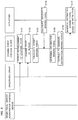
- FIG. 2 is a sequence diagram showing a process of the braking force control system according to the embodiment of the present invention
- FIG. 3 is a graph showing an example of a target braking force map according to the embodiment of the present invention.
- FIG. 4 is a graph showing an example of the target braking force map according to the embodiment of the present invention.
- FIG. 5 is a graph showing an example of the target braking force map according to the embodiment of the present invention.
- FIG. 6 is a graph showing an example of a braking force and a target braking force during coasting driving in conventional art.
- a braking force control system calculates a suitable target braking force on the basis of a vehicle speed, etc., in a coasting state of a vehicle, collectively performs cooperative control of a plurality of actuators such as a brake and a transmission, and causes each actuator to generate a braking force within a range where a braking force is generable by the actuator, thereby achieving a target braking force.
- FIG. 1 shows a functional block diagram of a braking force control system 10 according to the present embodiment, and a peripheral portion thereof.
- the braking force control system 10 includes a braking force control device 100 and a plurality of actuators 400 (400-1 to 400-N).
- the actuators 400 are a brake, an alternator, an engine, a transmission, etc., which can generate a braking force in a vehicle that is running.
- the braking force control device 100 includes a coasting state detection unit 11 , a target braking force calculation unit 12 , and a braking force distribution control unit 13 .
- the braking force control system 10 is provided in the vehicle and connected to a brake pedal sensor 201 , an accelerator position sensor 202 , and a sensor/ECU group 203 including other various sensors and a control unit called an ECU.
- the braking force control device 100 acquires information representing various states of the vehicle and the vehicle periphery that are detected or controlled by the brake pedal sensor 201 , the accelerator position sensor 202 , and the sensor/ECU group 203 , and controls the actuators 400 on the basis of the acquired information.
- FIG. 2 is a sequence diagram illustrating the process.
- FIGS. 3, 4, and 5 are each a diagram showing an example of a map used for calculating a target braking force. The process is started when a user performs coasting driving in which the user does not perform an accelerator operation and does not perform a brake operation.
- Step S 101 The coasting state detection unit 11 acquires information representing that a brake depression amount and an accelerator position are 0, from the brake pedal sensor 201 and the accelerator position sensor 202 , respectively, and detects that a coasting state has been established.
- Step S 102 The target braking force calculation unit 12 acquires a running state, a control state, and the ambient environment of the vehicle, as a state of the vehicle, from the sensor/ECU group 203 .
- the target braking force calculation unit 12 acquires a vehicle speed from a vehicle speed sensor or the like, acquires a drive mode representing a running characteristic designated by the user, from an ECU that manages various driving characteristics of the vehicle, or acquires the gradient of a road surface from an acceleration sensor or the like.
- the target braking force calculation unit 12 may acquire map information from a car navigation system, or acquire information about another vehicle or an obstacle around the vehicle, etc., from a camera or a radar.
- Step S 103 The target braking force calculation unit 12 calculates a target braking force, as a suitable braking force estimated to be expected by the user, on the basis of the vehicle state. Examples of a method for calculating a target braking force will be described with reference to FIGS. 3, 4, and 5 .
- a map that determines a target braking force with respect to a vehicle speed in advance is used. In each example, settings are made such that a braking force is generated when a vehicle speed exceeds a predetermined value V 0 , and is increased as the vehicle speed increases. In the example shown in FIG.
- a drive mode representing a running characteristic designated by the user in consideration of a drive mode representing a running characteristic designated by the user, settings are made such that, when the drive mode is an eco mode that designates running with low fuel consumption, a braking force is lower than that in the case of a normal mode that is a drive mode other than the eco mode.
- a map shown in FIG. 3 is used as a map for the case of the normal mode, and a map for the eco mode shown in FIG. 4 can be generated by using a value obtained by multiplying a value in the map shown in FIG. 3 by a coefficient ⁇ that is lower than 1.
- ⁇ that is lower than 1.
- settings are made such that, when a road surface is downhill, a braking force is made larger than that in the case of a flat road.
- the map shown in FIG. 3 is used as a map for the case of a flat road, and a map for a downhill road shown in FIG. 5 can be generated by using a value obtained by multiplying a value in the map shown in FIG. 3 by a coefficient ⁇ that is higher than 1.
- settings may be made such that, when a road surface is uphill, a braking force is made smaller than that in the case of a flat road.
- a map for an uphill road can be generated by using a value obtained by multiplying a value in the map shown in FIG. 3 by a coefficient ⁇ that is lower than 1.
- a target braking force may be calculated on the basis of both the drive mode and the road surface gradient.
- the map shown in FIG. 3 is used as a map for the case of a flat road and the normal mode, and a map for a downhill road and the eco mode can be generated by using a value obtained by multiplying a value in the map shown in FIG. 3 by the coefficient ⁇ and the coefficient ⁇ .
- a map for an uphill road and the eco mode can be generated by using a value obtained by multiplying a value in the map shown in FIG. 3 by the coefficient ⁇ and the coefficient ⁇ .
- another state may be used. For example, when presence of another vehicle within a predetermined distance in front of the vehicle is detected by a camera or a radar, a larger target braking force may be calculated than when such a vehicle is not present.
- a particularly suitable target braking force that fulfills a user's expectation can be calculated in accordance with various states of the vehicle.
- the above description is merely illustrative, and the method for calculating a target braking force is not particularly limited. As described above, a target braking force may be calculated by using different coefficients in accordance with the state of the vehicle, or a map that is individually generated in advance for each state may be used.
- Each actuator 400 includes a calculation unit that calculates a generable braking force.
- the generable braking force can be calculated on the basis of one or a combination of a rating, an estimated friction material temperature based on latest use history within a predetermined period, a braking torque request value from another control system, etc.
- the generable braking force can be calculated on the basis of one or a combination of a rating, a battery temperature, a battery charge amount (SOC), a charge/discharge request value from another control system, etc.
- the generable braking force can be calculated on the basis of one or a combination of a catalyst warm-up state, a fuel cut request from another control system, etc.
- the generable braking force can be calculated with constant accuracy on the basis of one or a combination of the level of noise generated in accordance with an engine speed and assumed at the time of downshifting, a gear shift request from another control system, etc.
- Each actuator 400 is not limited to these devices, and may be another device, or the generable braking force may be calculated on the basis of factors other than the above-described factors.
- the calculation unit of each actuator 400 notifies the braking force control device 100 of the calculated generable braking force.
- the calculation unit of each actuator 400 may perform such calculation and notification of the generable braking force at all times or in response to a request from the braking force control device 100 .
- the calculation unit of each actuator 400 calculates the generable braking force on the basis of the characteristics, the state, etc., of the actuator 400 , and thus the generable braking force of each actuator 400 can be accurately calculated.
- Step S 105 The braking force distribution control unit 13 allocates a distribution braking force to each actuator 400 on the basis of the generable braking force calculated by the calculation unit of each actuator 400 and the target braking force calculated by the target braking force calculation unit 12 .
- the distribution braking force to be allocated to each actuator 400 is, for example, determined such that the distribution braking force is equal to or less than the braking force generable by the actuator 400 and the sum of the respective distribution braking forces is equal to the target braking force. That is, each distribution braking force is determined so as to satisfy a restrictive formula of Expression (1) below and also satisfy Expression (2).
- an upper limit is provided as a restriction, and a lower limit is assumed to be 0.
- a restriction that the lower limit of a braking force is larger than 0 can occur in accordance with a request from another control system. For example, in some cases, in an alternator, a request for generating power at high priority is received from a control system for a power supply when the amount of power stored in a battery is reduced, and power is generated in response to the request, whereby a braking force is generated.
- the braking force distribution control unit 13 may also acquire such a lower limit as a generable braking force calculated by the calculation unit of each actuator 400 , and determine each distribution braking force such that the above-described Expressions (1) and (2) are satisfied and Expression (3) below is further satisfied.
- Priority may be provided for each actuator 400 on the basis of a predetermined control policy, and actuators 400 to which distribution braking forces is to be allocated and values of the distribution braking forces may be determined in order of the priority. That is, a distribution braking force that is as large as possible such that each expression described above is satisfied may be allocated in order starting from the actuator 400 with highest priority, and a distribution braking force that is as small as possible may be allocated to the actuator 400 with lowest priority.
- the priority can be determined such that the priority is increased when durability is higher, fuel consumption is lower, or a period when a braking force can be continuously generated is longer.
- the actuators 400 among the transmission, the engine, the alternator, and the brake, the engine and the transmission, which constantly operate and generate or transmit a large force during running, generally have particularly high durability.
- the transmission gear shift down
- the engine fuel cut
- the alternator power generation
- the brake when the transmission (gear shift down), the engine (fuel cut), the alternator (power generation), and the brake are higher in durability in this order, the transmission, the engine, the alternator, and the brake can be also set to be higher in priority in this order.
- Some of the actuators 400 have a characteristic that it is temporarily hard to generate a braking force.
- the above-described priority may be increased for the actuator 400 having a higher possibility of being caused to generate a braking force at arbitrary timing.
- the brake which is designed to generate a braking force as a main purpose and has no factor that should inhibit generation of a braking force, generally has a highest possibility of being caused to generate a braking force at arbitrary timing.
- the brake, the transmission, the engine, and the alternator when the brake, the transmission, the engine, and the alternator are higher, in this order, in possibility of being caused to generate a braking force at arbitrary timing, the brake, the transmission, the engine, and the alternator can be also set to be higher in priority in this order.
- the above-described priority may be increased for the actuator 400 having a larger generable braking force (braking torque amount).
- the brake which is designed to generate a braking force as a main purpose, is generally caused to generate a largest braking force.
- the transmission and the engine have higher mechanical resistance of internal components than the alternator, and can generate a larger braking force than the alternator.
- the brake, the transmission, the engine, and the alternator can be also set to be higher in priority in this order.
- the above-described priority may be increased for the actuator 400 of which a braking force is easily controlled.
- the brake which is designed to generate a braking force as a main purpose, generally has a high possibility of being caused to accurately generate a desired braking force.
- the transmission and the alternator can control a braking force stepwise by changing a gear ratio and an amount of power generated, respectively, stepwise, as compared to fuel cut of the engine.
- the brake, the transmission, the alternator, and the engine when the brake, the transmission, the alternator, and the engine are higher, in this order, in possibility of being caused to accurately generate a braking force, the brake, the transmission, the alternator, and the engine can be also set to be higher in priority in this order.
- the above-described priority may be increased for the actuator 400 that is less susceptible to influence of disturbance and have more stable characteristics.
- a braking force of the transmission is determined in accordance with the gear ratio and is relatively less susceptible to influence of other factors.
- the operating characteristics of the alternator easily change depending on a difference in charge/discharge ability due to the temperature of the battery, etc.
- the transmission, the engine, the brake, and the alternator can be also set to be higher in priority in this order.
- the above-described priority may be increased for the actuator 400 that less adversely influences fuel economy.
- fuel cut in the engine and regenerative power generation by the alternator contribute to improvement of fuel economy.
- the engine, the alternator, the transmission, and the brake can be also set to be higher in priority in this order.
- the above-described orders of priority are merely examples, and the methods for determining an order of priority and distribution braking forces are not limited to those described above.
- the engine, the transmission, the alternator, and the brake can be set to be higher in priority in this order.
- the engine and the transmission are preferentially used, so that deterioration of fuel economy can be inhibited by fuel cut of the engine and a braking force can be stably and effectively generated by the transmission.
- the order of priority may be set in accordance with the vehicle type, the drive mode, or the like.
- priority may be set in order of the engine, the alternator, the transmission, and the brake, starting from one having a smaller adverse effect on fuel economy, and, in another mode, priority may be set in order of the transmission, the engine, the alternator, and the brake, starting from one having higher durability.
- Step S 106 The braking force distribution control unit 13 instructs each actuator 400 to generate the allocated distribution braking force.
- Step S 107 Each actuator 400 generates the distribution braking force in response to the instruction.
- step S 102 to step S 106 are repeated, and braking force control corresponding to the speed of the vehicle or the like is continued.
- step S 101 is executed again.
- a motor only needs to be used instead of the engine, etc., as an actuator.
- each component of the braking force control system is not limited to that in the present embodiment, and can be variously modified as long as the functions of: the plurality of actuators capable of generating a braking force for the vehicle; the target braking force calculation unit, which calculates a target braking force on the basis of the state of the vehicle; and the braking force distribution control unit, which determines a distribution braking force to be allocated to each actuator, such that the sum of the distribution braking forces is equal to the target braking force, and performs control of causing each actuator to generate the distribution braking force, when an accelerator operation is not performed and a brake operation is not performed during running of the vehicle, can be achieved.
- the plurality of actuators 400 may be actuators other than the brake, the alternator, the engine, and the transmission described as examples, as long as the actuators are functional units that are provided in the vehicle and capable of generating a braking force, and a combination of actuators is not limited as long as the number of the actuators is two or more.
- the braking force control system 10 may receive a target braking force, in the form of a braking force (N) or the like, from the movement manager.
- the braking force control system 10 does not have to calculate a target braking force, and thus does not have to include the coasting state detection unit 11 and the target braking force calculation unit 12 .
- the braking force control system 10 does not have to acquire information from the brake pedal sensor 201 , the accelerator position sensor 202 , the sensor/ECU group 203 , etc.
- the braking force distribution control unit 13 notifies the movement manager of the range (availability) of the present generable braking force (N).
- the movement manager receives an acceleration/deceleration request, in the form of acceleration (m/s 2 ) or the like, from at least still another in-vehicle device having a function to determine acceleration/deceleration or the like of the vehicle on the basis of information of various sensors or the like for driving assistance, and determines a target braking force within the range of the availability on the basis of the request and at least the availability.
- an acceleration/deceleration request in the form of acceleration (m/s 2 ) or the like
- the movement manager receives an acceleration/deceleration request, in the form of acceleration (m/s 2 ) or the like, from at least still another in-vehicle device having a function to determine acceleration/deceleration or the like of the vehicle on the basis of information of various sensors or the like for driving assistance, and determines a target braking force within the range of the availability on the basis of the request and at least the availability.
- the braking force distribution control unit 13 acquires a target braking force from the movement manager as described above.
- the braking force control system 10 can receive a target braking force that matches with an acceleration/deceleration request from another in-vehicle device for performing various types of driving assistance, without independently calculating a target braking force. Accordingly, overlap of processes can be eliminated, and designing and mounting can be made easy, so that extension of a driving assistance function in the future can be easily handled.
- the braking force control system 10 may be mounted as a part of an integral driving assistance system that assumes use of a movement manager.
- a suitable target braking force expected by the user in a coasting state of the vehicle, can be estimated on the basis of various states of the vehicle, and cooperative control of the plurality of actuators can be performed to generate a braking force such that the target braking force is achieved.
- suitable braking force control can be performed.
- the present invention can be taken not only as a braking force control system including a braking force control device and actuators, but also as a method or a program to be executed by the braking force control device and a computer thereof, a computer-readable non-transitory storage medium having the program stored therein, or a vehicle including the braking force control system.
- the present invention is useful for a braking force control system for a vehicle or the like.
Landscapes
- Engineering & Computer Science (AREA)
- Transportation (AREA)
- Mechanical Engineering (AREA)
- Chemical & Material Sciences (AREA)
- Combustion & Propulsion (AREA)
- Automation & Control Theory (AREA)
- Regulating Braking Force (AREA)
- Control Of Driving Devices And Active Controlling Of Vehicle (AREA)
- Control Of Transmission Device (AREA)
- Human Computer Interaction (AREA)
- Physics & Mathematics (AREA)
- Mathematical Physics (AREA)
Priority Applications (2)
| Application Number | Priority Date | Filing Date | Title |
|---|---|---|---|
| US17/226,530 US11697415B2 (en) | 2018-03-07 | 2021-04-09 | Braking force control system, device, and method |
| US17/382,892 USRE49777E1 (en) | 2018-03-07 | 2021-07-22 | Braking force control system, device, and method |
Applications Claiming Priority (6)
| Application Number | Priority Date | Filing Date | Title |
|---|---|---|---|
| JP2018040871 | 2018-03-07 | ||
| JP2018-040871 | 2018-03-07 | ||
| JPJP2018-040871 | 2018-03-07 | ||
| JPJP2018-145972 | 2018-08-02 | ||
| JP2018-145972 | 2018-08-02 | ||
| JP2018145972A JP7310102B2 (ja) | 2018-03-07 | 2018-08-02 | 制動力制御システム、制御装置、マネージャ、方法、プログラム、アクチュエータシステム、および車両 |
Related Child Applications (2)
| Application Number | Title | Priority Date | Filing Date |
|---|---|---|---|
| US17/226,530 Continuation US11697415B2 (en) | 2018-03-07 | 2021-04-09 | Braking force control system, device, and method |
| US17/382,892 Reissue USRE49777E1 (en) | 2018-03-07 | 2021-07-22 | Braking force control system, device, and method |
Publications (2)
| Publication Number | Publication Date |
|---|---|
| US20190276026A1 US20190276026A1 (en) | 2019-09-12 |
| US11001263B2 true US11001263B2 (en) | 2021-05-11 |
Family
ID=65433605
Family Applications (3)
| Application Number | Title | Priority Date | Filing Date |
|---|---|---|---|
| US16/272,000 Ceased US11001263B2 (en) | 2018-03-07 | 2019-02-11 | Braking force control system, device, and method |
| US17/226,530 Active US11697415B2 (en) | 2018-03-07 | 2021-04-09 | Braking force control system, device, and method |
| US17/382,892 Active 2039-02-26 USRE49777E1 (en) | 2018-03-07 | 2021-07-22 | Braking force control system, device, and method |
Family Applications After (2)
| Application Number | Title | Priority Date | Filing Date |
|---|---|---|---|
| US17/226,530 Active US11697415B2 (en) | 2018-03-07 | 2021-04-09 | Braking force control system, device, and method |
| US17/382,892 Active 2039-02-26 USRE49777E1 (en) | 2018-03-07 | 2021-07-22 | Braking force control system, device, and method |
Country Status (5)
| Country | Link |
|---|---|
| US (3) | US11001263B2 (de) |
| EP (3) | EP4257442B8 (de) |
| JP (1) | JP7650434B2 (de) |
| KR (3) | KR20220026555A (de) |
| CN (2) | CN116946139A (de) |
Cited By (4)
| Publication number | Priority date | Publication date | Assignee | Title |
|---|---|---|---|---|
| US11618435B2 (en) | 2020-04-21 | 2023-04-04 | Toyota Jidosha Kabushiki Kaisha | Vehicle control system and vehicle control method |
| US11620904B2 (en) | 2021-03-03 | 2023-04-04 | Toyota Jidosha Kabushiki Kaisha | Vehicle control method, vehicle control system, and information processing device |
| US11634135B2 (en) | 2020-08-03 | 2023-04-25 | Toyota Jidosha Kabushiki Kaisha | Driving support control device for vehicle |
| US11760353B2 (en) * | 2018-08-07 | 2023-09-19 | Toyota Jidosha Kabushiki Kaisha | Braking force control device |
Families Citing this family (6)
| Publication number | Priority date | Publication date | Assignee | Title |
|---|---|---|---|---|
| KR102882420B1 (ko) * | 2019-12-16 | 2025-11-06 | 현대자동차주식회사 | 전기자동차의 회생제동토크 제어 장치 및 그 방법 |
| CN113002321A (zh) * | 2021-03-23 | 2021-06-22 | 奇瑞新能源汽车股份有限公司 | 新能源汽车的刹车方法、装置、整车控制器及新能源汽车 |
| EP4166398B1 (de) * | 2021-10-15 | 2025-07-16 | KNORR-BREMSE Systeme für Nutzfahrzeuge GmbH | Verfahren zur steuerung einer mehrzahl von bremsmitteln und bremssystem eines fahrzeugs |
| CN113844423A (zh) * | 2021-11-09 | 2021-12-28 | 盐城工学院 | 一种新能源汽车电机制动系统 |
| CN114347974B (zh) * | 2022-01-24 | 2023-12-19 | 神龙汽车有限公司 | 混合动力汽车制动扭矩控制方法、存储介质 |
| JP2024179965A (ja) * | 2023-06-16 | 2024-12-26 | トヨタ自動車株式会社 | 車両の制御装置、車両の制御方法、及び車両の制御プログラム |
Citations (14)
| Publication number | Priority date | Publication date | Assignee | Title |
|---|---|---|---|---|
| JPH10280990A (ja) | 1997-04-04 | 1998-10-20 | Toyota Motor Corp | 内燃機関の燃料カット制御装置 |
| JPH1132404A (ja) * | 1997-06-24 | 1999-02-02 | Nabco Ltd | 電気自動車の走行制御装置 |
| DE10334536A1 (de) | 2002-07-29 | 2004-02-12 | Robert Bosch Gmbh | Computersystem und Verfahren zur Steuerung, insbesondere zur koordinierten Antriebsstrangsteuerung eines Kraftfahrzeuges |
| US20050187694A1 (en) * | 2004-02-10 | 2005-08-25 | Toyota Jidosha Kabushiki Kaisha | Deceleration control apparatus and method for a vehicle |
| US20050218718A1 (en) | 2004-04-06 | 2005-10-06 | Toyota Jidosha Kabushiki Kaisha | Deceleration control apparatus and method for a vehicle |
| WO2006042628A1 (de) | 2004-10-20 | 2006-04-27 | Bayerische Motoren Werke Aktiengesellschaft | Verfahren zur steuerung eines antriebssystems und/oder eines radbremssystems |
| US20060173601A1 (en) | 2002-07-29 | 2006-08-03 | Dirk Bassiere | Computer system and method for controlling, particularly for executing the coordinated drive train control of a motor vehicle |
| US20060241844A1 (en) * | 2005-04-21 | 2006-10-26 | Yukio Mori | Vehicle speed control apparatus |
| JP2006297994A (ja) | 2005-04-15 | 2006-11-02 | Toyota Motor Corp | 車両統合制御装置 |
| JP2010151154A (ja) | 2008-12-24 | 2010-07-08 | Daihatsu Motor Co Ltd | 車両の制御装置 |
| WO2013084697A1 (ja) | 2011-12-06 | 2013-06-13 | 日産自動車株式会社 | 車両のエンジン自動制御装置 |
| EP3100926A1 (de) | 2014-01-30 | 2016-12-07 | BYD Company Limited | Fahrzeug und schieberückkopplungsverfahren dafür |
| WO2018190022A1 (ja) * | 2017-04-14 | 2018-10-18 | 日産自動車株式会社 | ハイブリッド車両の制御方法及び制御装置 |
| US20190299995A1 (en) * | 2018-04-03 | 2019-10-03 | Toyota Jidosha Kabushiki Kaisha | Vehicle control apparatus |
Family Cites Families (45)
| Publication number | Priority date | Publication date | Assignee | Title |
|---|---|---|---|---|
| JP2605827B2 (ja) | 1988-09-19 | 1997-04-30 | 松下電器産業株式会社 | 移動体識別用応答器 |
| JPH11266505A (ja) * | 1998-03-18 | 1999-09-28 | Nippon Yusoki Co Ltd | 電気車の走行制御方法 |
| JP3838048B2 (ja) | 2001-04-16 | 2006-10-25 | 日産自動車株式会社 | 車両用走行制御装置 |
| JP3744414B2 (ja) | 2001-11-29 | 2006-02-08 | トヨタ自動車株式会社 | 車両の制御装置 |
| JP3956693B2 (ja) | 2001-12-27 | 2007-08-08 | トヨタ自動車株式会社 | 統合型車両運動制御装置 |
| JP3921109B2 (ja) | 2002-03-20 | 2007-05-30 | 日産ディーゼル工業株式会社 | 車両のハイブリッドシステム |
| JP4244804B2 (ja) * | 2003-12-25 | 2009-03-25 | トヨタ自動車株式会社 | 車両の統合制御システム |
| JP2005186831A (ja) * | 2003-12-26 | 2005-07-14 | Toyota Motor Corp | 車両の統合制御システム |
| JP2005253126A (ja) | 2004-03-01 | 2005-09-15 | Nissan Motor Co Ltd | ハイブリッド車両の制動力制御装置および該制御装置を搭載した車両 |
| JP2006240394A (ja) * | 2005-03-01 | 2006-09-14 | Toyota Motor Corp | 車輌の制駆動力制御装置 |
| JP2007069787A (ja) * | 2005-09-08 | 2007-03-22 | Nissan Motor Co Ltd | ハイブリッド車両の減速制御装置 |
| JP4992265B2 (ja) * | 2006-03-28 | 2012-08-08 | トヨタ自動車株式会社 | 車両走行制御装置および車両走行制御方法 |
| US7689341B2 (en) * | 2007-11-29 | 2010-03-30 | International Truck Intellectual Property Company, Llc | Prioritized recapture of energy during deceleration of a dual-hybrid motor vehicle |
| JP2009210510A (ja) | 2008-03-06 | 2009-09-17 | Hitachi Ltd | 車両運転支援システムおよび車両運転支援方法 |
| JP5229393B2 (ja) * | 2009-09-02 | 2013-07-03 | トヨタ自動車株式会社 | ブレーキ制御装置 |
| WO2012056540A1 (ja) | 2010-10-27 | 2012-05-03 | トヨタ自動車株式会社 | 車両用動力伝達装置の制御装置 |
| WO2012144058A1 (ja) * | 2011-04-21 | 2012-10-26 | パイオニア株式会社 | トルク配分装置、トルク配分方法、トルク配分値生成方法およびプログラム |
| WO2013030923A1 (ja) | 2011-08-29 | 2013-03-07 | トヨタ自動車株式会社 | 車両の制動力制御装置 |
| JP2013105456A (ja) | 2011-11-16 | 2013-05-30 | Toyota Motor Corp | 運転支援システム |
| WO2013076806A1 (ja) | 2011-11-22 | 2013-05-30 | パイオニア株式会社 | 車両駆動装置 |
| CN103448720B (zh) * | 2013-06-04 | 2015-11-04 | 浙江吉利汽车研究院有限公司杭州分公司 | 汽车爆胎防追尾控制方法及控制装置 |
| JP6303310B2 (ja) | 2013-07-23 | 2018-04-04 | 日産自動車株式会社 | 車両挙動制御装置及び車両挙動制御方法 |
| JP2015051672A (ja) * | 2013-09-05 | 2015-03-19 | 日立オートモティブシステムズ株式会社 | ブレーキシステム及びブレーキ装置及びブレーキ制御方法 |
| JP6164141B2 (ja) * | 2014-03-31 | 2017-07-19 | 株式会社アドヴィックス | 車両の運転支援装置 |
| JP6361916B2 (ja) * | 2014-07-11 | 2018-07-25 | 日立オートモティブシステムズ株式会社 | 車両制御装置および車両制御方法 |
| JP6142854B2 (ja) * | 2014-08-20 | 2017-06-07 | トヨタ自動車株式会社 | 車両制御装置及び車両制御方法 |
| GB201420988D0 (en) * | 2014-11-26 | 2015-01-07 | Tomtom Telematics Bv | Apparatus and method for vehicle economy improvement |
| CN105774564B (zh) * | 2014-12-19 | 2018-06-12 | 北汽福田汽车股份有限公司 | 一种混合动力车能量回馈方法及系统 |
| JP6539455B2 (ja) * | 2015-02-10 | 2019-07-03 | ナブテスコ株式会社 | ブレーキ制御装置およびブレーキ制御方法 |
| JP6458324B2 (ja) * | 2015-03-23 | 2019-01-30 | 日立オートモティブシステムズ株式会社 | 車両用の制動制御装置 |
| KR102224165B1 (ko) * | 2015-06-25 | 2021-03-05 | 현대자동차주식회사 | 하이브리드 차량의 제동 선형성 개선을 위한 모터토크 제어방법 |
| WO2017006440A1 (ja) * | 2015-07-07 | 2017-01-12 | 日産自動車株式会社 | ハイブリッド車両の駆動力制御装置 |
| JP6332181B2 (ja) | 2015-07-16 | 2018-05-30 | トヨタ自動車株式会社 | 車両の制御装置 |
| CN106800020B (zh) * | 2015-11-24 | 2024-01-23 | 广州汽车集团股份有限公司 | 一种四驱混合动力系统及其控制方法 |
| JP6335958B2 (ja) * | 2016-03-10 | 2018-05-30 | 本田技研工業株式会社 | 車両用制動装置 |
| US10202120B2 (en) * | 2016-06-01 | 2019-02-12 | Ford Global Technologies, Llc | Methods and system for decelerating a vehicle |
| JP6774250B2 (ja) | 2016-07-27 | 2020-10-21 | 株式会社Subaru | 車両の制動力制御装置 |
| US9855951B1 (en) * | 2016-11-11 | 2018-01-02 | Caterpillar Inc. | CVT target engine speed control for coasting and retarding |
| KR102417515B1 (ko) | 2016-11-24 | 2022-07-05 | 현대자동차주식회사 | 전기자동차의 제동 제어 장치 및 방법 |
| CN107499143A (zh) * | 2017-08-11 | 2017-12-22 | 上海蓥石汽车技术有限公司 | 一种可扩展的再生制动控制系统 |
| CN107685657B (zh) * | 2017-08-31 | 2020-04-17 | 奇瑞新能源汽车技术有限公司 | 车辆制动方法和装置 |
| CN111527295B (zh) * | 2017-12-28 | 2022-07-22 | 本田技研工业株式会社 | 鞍乘型车辆 |
| JP7310102B2 (ja) * | 2018-03-07 | 2023-07-19 | トヨタ自動車株式会社 | 制動力制御システム、制御装置、マネージャ、方法、プログラム、アクチュエータシステム、および車両 |
| JP6973314B2 (ja) * | 2018-07-17 | 2021-11-24 | トヨタ自動車株式会社 | 制御装置、マネージャ、システム、制御方法及び車両 |
| US11554771B2 (en) * | 2020-08-14 | 2023-01-17 | Ford Global Technologies, Llc | Hybrid vehicle with optimized transmission control during regenerative braking |
-
2019
- 2019-02-11 US US16/272,000 patent/US11001263B2/en not_active Ceased
- 2019-02-13 EP EP23193027.2A patent/EP4257442B8/de active Active
- 2019-02-13 EP EP25218741.4A patent/EP4678496A3/de active Pending
- 2019-02-13 EP EP19156961.5A patent/EP3536569B1/de active Active
- 2019-03-04 CN CN202311131782.8A patent/CN116946139A/zh active Pending
- 2019-03-04 CN CN201910161279.4A patent/CN110239543B/zh active Active
-
2021
- 2021-04-09 US US17/226,530 patent/US11697415B2/en active Active
- 2021-07-22 US US17/382,892 patent/USRE49777E1/en active Active
-
2022
- 2022-02-14 KR KR1020220019044A patent/KR20220026555A/ko not_active Ceased
-
2023
- 2023-06-29 JP JP2023106977A patent/JP7650434B2/ja active Active
- 2023-11-27 KR KR1020230167278A patent/KR20230166992A/ko not_active Ceased
-
2024
- 2024-12-27 KR KR1020240198484A patent/KR20250006793A/ko active Pending
Patent Citations (17)
| Publication number | Priority date | Publication date | Assignee | Title |
|---|---|---|---|---|
| JPH10280990A (ja) | 1997-04-04 | 1998-10-20 | Toyota Motor Corp | 内燃機関の燃料カット制御装置 |
| JPH1132404A (ja) * | 1997-06-24 | 1999-02-02 | Nabco Ltd | 電気自動車の走行制御装置 |
| DE10334536A1 (de) | 2002-07-29 | 2004-02-12 | Robert Bosch Gmbh | Computersystem und Verfahren zur Steuerung, insbesondere zur koordinierten Antriebsstrangsteuerung eines Kraftfahrzeuges |
| US20060173601A1 (en) | 2002-07-29 | 2006-08-03 | Dirk Bassiere | Computer system and method for controlling, particularly for executing the coordinated drive train control of a motor vehicle |
| US20050187694A1 (en) * | 2004-02-10 | 2005-08-25 | Toyota Jidosha Kabushiki Kaisha | Deceleration control apparatus and method for a vehicle |
| US20050218718A1 (en) | 2004-04-06 | 2005-10-06 | Toyota Jidosha Kabushiki Kaisha | Deceleration control apparatus and method for a vehicle |
| WO2006042628A1 (de) | 2004-10-20 | 2006-04-27 | Bayerische Motoren Werke Aktiengesellschaft | Verfahren zur steuerung eines antriebssystems und/oder eines radbremssystems |
| US20070207895A1 (en) | 2004-10-20 | 2007-09-06 | Bayerische Motoren Werke Aktiengesellschaft | Method for controlling a drive system and/or a wheel brake system |
| JP2006297994A (ja) | 2005-04-15 | 2006-11-02 | Toyota Motor Corp | 車両統合制御装置 |
| US20090259370A1 (en) | 2005-04-15 | 2009-10-15 | Toyota Jidosha Kabushiki Kaisha | Vehicle Integrated-Control Apparatus and Vehicle Integrated-Control Method |
| US20060241844A1 (en) * | 2005-04-21 | 2006-10-26 | Yukio Mori | Vehicle speed control apparatus |
| JP2010151154A (ja) | 2008-12-24 | 2010-07-08 | Daihatsu Motor Co Ltd | 車両の制御装置 |
| WO2013084697A1 (ja) | 2011-12-06 | 2013-06-13 | 日産自動車株式会社 | 車両のエンジン自動制御装置 |
| US20140336907A1 (en) | 2011-12-06 | 2014-11-13 | Nissan Motor Co., Ltd. | Vehicle engine automatic control device and vehicle engine automatic control method |
| EP3100926A1 (de) | 2014-01-30 | 2016-12-07 | BYD Company Limited | Fahrzeug und schieberückkopplungsverfahren dafür |
| WO2018190022A1 (ja) * | 2017-04-14 | 2018-10-18 | 日産自動車株式会社 | ハイブリッド車両の制御方法及び制御装置 |
| US20190299995A1 (en) * | 2018-04-03 | 2019-10-03 | Toyota Jidosha Kabushiki Kaisha | Vehicle control apparatus |
Cited By (5)
| Publication number | Priority date | Publication date | Assignee | Title |
|---|---|---|---|---|
| US11760353B2 (en) * | 2018-08-07 | 2023-09-19 | Toyota Jidosha Kabushiki Kaisha | Braking force control device |
| US12168442B2 (en) | 2018-08-07 | 2024-12-17 | Toyota Jidosha Kabushiki Kaisha | Braking force control device |
| US11618435B2 (en) | 2020-04-21 | 2023-04-04 | Toyota Jidosha Kabushiki Kaisha | Vehicle control system and vehicle control method |
| US11634135B2 (en) | 2020-08-03 | 2023-04-25 | Toyota Jidosha Kabushiki Kaisha | Driving support control device for vehicle |
| US11620904B2 (en) | 2021-03-03 | 2023-04-04 | Toyota Jidosha Kabushiki Kaisha | Vehicle control method, vehicle control system, and information processing device |
Also Published As
| Publication number | Publication date |
|---|---|
| US11697415B2 (en) | 2023-07-11 |
| KR20230166992A (ko) | 2023-12-07 |
| EP4257442A2 (de) | 2023-10-11 |
| EP3536569A2 (de) | 2019-09-11 |
| KR20220026555A (ko) | 2022-03-04 |
| EP4678496A2 (de) | 2026-01-14 |
| EP4257442B1 (de) | 2026-01-14 |
| USRE49777E1 (en) | 2024-01-02 |
| US20210221376A1 (en) | 2021-07-22 |
| US20190276026A1 (en) | 2019-09-12 |
| JP2023115302A (ja) | 2023-08-18 |
| EP4257442C0 (de) | 2026-01-14 |
| EP4257442A3 (de) | 2023-12-13 |
| CN110239543B (zh) | 2023-09-29 |
| EP3536569B1 (de) | 2023-10-18 |
| BR102019004071A2 (pt) | 2019-09-17 |
| CN110239543A (zh) | 2019-09-17 |
| EP3536569A3 (de) | 2019-11-13 |
| JP7650434B2 (ja) | 2025-03-25 |
| EP4257442B8 (de) | 2026-03-18 |
| CN116946139A (zh) | 2023-10-27 |
| KR20250006793A (ko) | 2025-01-13 |
| EP4678496A3 (de) | 2026-03-04 |
Similar Documents
| Publication | Publication Date | Title |
|---|---|---|
| USRE49777E1 (en) | Braking force control system, device, and method | |
| JP6919316B2 (ja) | 車両制御装置 | |
| US11498560B2 (en) | Braking force controller | |
| KR20120049279A (ko) | 차량 제어 시스템 | |
| CN111770863B (zh) | 车辆控制方法及设备 | |
| US20230018675A1 (en) | Braking force control device | |
| KR102226870B1 (ko) | 제동력 제어 시스템, 장치 및 방법 | |
| US11453377B2 (en) | Braking force control apparatus | |
| JP4480752B2 (ja) | 車両エンジンの制御装置 | |
| JP7533130B2 (ja) | 車両制御装置 | |
| JP7251298B2 (ja) | 制動力制御装置 | |
| BR102019004071B1 (pt) | Sistema, dispositivo e método de controle de força de frenagem | |
| JP2019182288A (ja) | 運転支援装置 |
Legal Events
| Date | Code | Title | Description |
|---|---|---|---|
| AS | Assignment |
Owner name: TOYOTA JIDOSHA KABUSHIKI KAISHA, JAPAN Free format text: ASSIGNMENT OF ASSIGNORS INTEREST;ASSIGNORS:SHIMIZU, MASATO;SATO, SHUN;KONO, KATSUMI;AND OTHERS;SIGNING DATES FROM 20181207 TO 20181210;REEL/FRAME:048301/0001 |
|
| FEPP | Fee payment procedure |
Free format text: ENTITY STATUS SET TO UNDISCOUNTED (ORIGINAL EVENT CODE: BIG.); ENTITY STATUS OF PATENT OWNER: LARGE ENTITY |
|
| STPP | Information on status: patent application and granting procedure in general |
Free format text: NON FINAL ACTION MAILED |
|
| STPP | Information on status: patent application and granting procedure in general |
Free format text: RESPONSE TO NON-FINAL OFFICE ACTION ENTERED AND FORWARDED TO EXAMINER |
|
| STPP | Information on status: patent application and granting procedure in general |
Free format text: NOTICE OF ALLOWANCE MAILED -- APPLICATION RECEIVED IN OFFICE OF PUBLICATIONS |
|
| STPP | Information on status: patent application and granting procedure in general |
Free format text: PUBLICATIONS -- ISSUE FEE PAYMENT RECEIVED |
|
| STPP | Information on status: patent application and granting procedure in general |
Free format text: PUBLICATIONS -- ISSUE FEE PAYMENT VERIFIED |
|
| STCF | Information on status: patent grant |
Free format text: PATENTED CASE |
|
| RF | Reissue application filed |
Effective date: 20210722 |
|
| RF | Reissue application filed |
Effective date: 20231016 |
|
| FEPP | Fee payment procedure |
Free format text: MAINTENANCE FEE REMINDER MAILED (ORIGINAL EVENT CODE: REM.); ENTITY STATUS OF PATENT OWNER: LARGE ENTITY |
|
| LAPS | Lapse for failure to pay maintenance fees |
Free format text: PATENT EXPIRED FOR FAILURE TO PAY MAINTENANCE FEES (ORIGINAL EVENT CODE: EXP.); ENTITY STATUS OF PATENT OWNER: LARGE ENTITY |
|
| STCH | Information on status: patent discontinuation |
Free format text: PATENT EXPIRED DUE TO NONPAYMENT OF MAINTENANCE FEES UNDER 37 CFR 1.362 |
|
| FP | Lapsed due to failure to pay maintenance fee |
Effective date: 20250511 |