WO2017006440A1 - ハイブリッド車両の駆動力制御装置 - Google Patents
ハイブリッド車両の駆動力制御装置 Download PDFInfo
- Publication number
- WO2017006440A1 WO2017006440A1 PCT/JP2015/069562 JP2015069562W WO2017006440A1 WO 2017006440 A1 WO2017006440 A1 WO 2017006440A1 JP 2015069562 W JP2015069562 W JP 2015069562W WO 2017006440 A1 WO2017006440 A1 WO 2017006440A1
- Authority
- WO
- WIPO (PCT)
- Prior art keywords
- driving force
- mode
- ice
- maximum
- hev
- Prior art date
Links
Images


Classifications
-
- B—PERFORMING OPERATIONS; TRANSPORTING
- B60—VEHICLES IN GENERAL
- B60K—ARRANGEMENT OR MOUNTING OF PROPULSION UNITS OR OF TRANSMISSIONS IN VEHICLES; ARRANGEMENT OR MOUNTING OF PLURAL DIVERSE PRIME-MOVERS IN VEHICLES; AUXILIARY DRIVES FOR VEHICLES; INSTRUMENTATION OR DASHBOARDS FOR VEHICLES; ARRANGEMENTS IN CONNECTION WITH COOLING, AIR INTAKE, GAS EXHAUST OR FUEL SUPPLY OF PROPULSION UNITS IN VEHICLES
- B60K6/00—Arrangement or mounting of plural diverse prime-movers for mutual or common propulsion, e.g. hybrid propulsion systems comprising electric motors and internal combustion engines ; Control systems therefor, i.e. systems controlling two or more prime movers, or controlling one of these prime movers and any of the transmission, drive or drive units Informative references: mechanical gearings with secondary electric drive F16H3/72; arrangements for handling mechanical energy structurally associated with the dynamo-electric machine H02K7/00; machines comprising structurally interrelated motor and generator parts H02K51/00; dynamo-electric machines not otherwise provided for in H02K see H02K99/00
- B60K6/20—Arrangement or mounting of plural diverse prime-movers for mutual or common propulsion, e.g. hybrid propulsion systems comprising electric motors and internal combustion engines ; Control systems therefor, i.e. systems controlling two or more prime movers, or controlling one of these prime movers and any of the transmission, drive or drive units Informative references: mechanical gearings with secondary electric drive F16H3/72; arrangements for handling mechanical energy structurally associated with the dynamo-electric machine H02K7/00; machines comprising structurally interrelated motor and generator parts H02K51/00; dynamo-electric machines not otherwise provided for in H02K see H02K99/00 the prime-movers consisting of electric motors and internal combustion engines, e.g. HEVs
- B60K6/50—Architecture of the driveline characterised by arrangement or kind of transmission units
- B60K6/54—Transmission for changing ratio
- B60K6/547—Transmission for changing ratio the transmission being a stepped gearing
-
- B—PERFORMING OPERATIONS; TRANSPORTING
- B60—VEHICLES IN GENERAL
- B60K—ARRANGEMENT OR MOUNTING OF PROPULSION UNITS OR OF TRANSMISSIONS IN VEHICLES; ARRANGEMENT OR MOUNTING OF PLURAL DIVERSE PRIME-MOVERS IN VEHICLES; AUXILIARY DRIVES FOR VEHICLES; INSTRUMENTATION OR DASHBOARDS FOR VEHICLES; ARRANGEMENTS IN CONNECTION WITH COOLING, AIR INTAKE, GAS EXHAUST OR FUEL SUPPLY OF PROPULSION UNITS IN VEHICLES
- B60K1/00—Arrangement or mounting of electrical propulsion units
- B60K1/02—Arrangement or mounting of electrical propulsion units comprising more than one electric motor
-
- B—PERFORMING OPERATIONS; TRANSPORTING
- B60—VEHICLES IN GENERAL
- B60K—ARRANGEMENT OR MOUNTING OF PROPULSION UNITS OR OF TRANSMISSIONS IN VEHICLES; ARRANGEMENT OR MOUNTING OF PLURAL DIVERSE PRIME-MOVERS IN VEHICLES; AUXILIARY DRIVES FOR VEHICLES; INSTRUMENTATION OR DASHBOARDS FOR VEHICLES; ARRANGEMENTS IN CONNECTION WITH COOLING, AIR INTAKE, GAS EXHAUST OR FUEL SUPPLY OF PROPULSION UNITS IN VEHICLES
- B60K6/00—Arrangement or mounting of plural diverse prime-movers for mutual or common propulsion, e.g. hybrid propulsion systems comprising electric motors and internal combustion engines ; Control systems therefor, i.e. systems controlling two or more prime movers, or controlling one of these prime movers and any of the transmission, drive or drive units Informative references: mechanical gearings with secondary electric drive F16H3/72; arrangements for handling mechanical energy structurally associated with the dynamo-electric machine H02K7/00; machines comprising structurally interrelated motor and generator parts H02K51/00; dynamo-electric machines not otherwise provided for in H02K see H02K99/00
- B60K6/20—Arrangement or mounting of plural diverse prime-movers for mutual or common propulsion, e.g. hybrid propulsion systems comprising electric motors and internal combustion engines ; Control systems therefor, i.e. systems controlling two or more prime movers, or controlling one of these prime movers and any of the transmission, drive or drive units Informative references: mechanical gearings with secondary electric drive F16H3/72; arrangements for handling mechanical energy structurally associated with the dynamo-electric machine H02K7/00; machines comprising structurally interrelated motor and generator parts H02K51/00; dynamo-electric machines not otherwise provided for in H02K see H02K99/00 the prime-movers consisting of electric motors and internal combustion engines, e.g. HEVs
- B60K6/22—Arrangement or mounting of plural diverse prime-movers for mutual or common propulsion, e.g. hybrid propulsion systems comprising electric motors and internal combustion engines ; Control systems therefor, i.e. systems controlling two or more prime movers, or controlling one of these prime movers and any of the transmission, drive or drive units Informative references: mechanical gearings with secondary electric drive F16H3/72; arrangements for handling mechanical energy structurally associated with the dynamo-electric machine H02K7/00; machines comprising structurally interrelated motor and generator parts H02K51/00; dynamo-electric machines not otherwise provided for in H02K see H02K99/00 the prime-movers consisting of electric motors and internal combustion engines, e.g. HEVs characterised by apparatus, components or means specially adapted for HEVs
- B60K6/38—Arrangement or mounting of plural diverse prime-movers for mutual or common propulsion, e.g. hybrid propulsion systems comprising electric motors and internal combustion engines ; Control systems therefor, i.e. systems controlling two or more prime movers, or controlling one of these prime movers and any of the transmission, drive or drive units Informative references: mechanical gearings with secondary electric drive F16H3/72; arrangements for handling mechanical energy structurally associated with the dynamo-electric machine H02K7/00; machines comprising structurally interrelated motor and generator parts H02K51/00; dynamo-electric machines not otherwise provided for in H02K see H02K99/00 the prime-movers consisting of electric motors and internal combustion engines, e.g. HEVs characterised by apparatus, components or means specially adapted for HEVs characterised by the driveline clutches
- B60K6/387—Actuated clutches, i.e. clutches engaged or disengaged by electric, hydraulic or mechanical actuating means
-
- B—PERFORMING OPERATIONS; TRANSPORTING
- B60—VEHICLES IN GENERAL
- B60K—ARRANGEMENT OR MOUNTING OF PROPULSION UNITS OR OF TRANSMISSIONS IN VEHICLES; ARRANGEMENT OR MOUNTING OF PLURAL DIVERSE PRIME-MOVERS IN VEHICLES; AUXILIARY DRIVES FOR VEHICLES; INSTRUMENTATION OR DASHBOARDS FOR VEHICLES; ARRANGEMENTS IN CONNECTION WITH COOLING, AIR INTAKE, GAS EXHAUST OR FUEL SUPPLY OF PROPULSION UNITS IN VEHICLES
- B60K6/00—Arrangement or mounting of plural diverse prime-movers for mutual or common propulsion, e.g. hybrid propulsion systems comprising electric motors and internal combustion engines ; Control systems therefor, i.e. systems controlling two or more prime movers, or controlling one of these prime movers and any of the transmission, drive or drive units Informative references: mechanical gearings with secondary electric drive F16H3/72; arrangements for handling mechanical energy structurally associated with the dynamo-electric machine H02K7/00; machines comprising structurally interrelated motor and generator parts H02K51/00; dynamo-electric machines not otherwise provided for in H02K see H02K99/00
- B60K6/20—Arrangement or mounting of plural diverse prime-movers for mutual or common propulsion, e.g. hybrid propulsion systems comprising electric motors and internal combustion engines ; Control systems therefor, i.e. systems controlling two or more prime movers, or controlling one of these prime movers and any of the transmission, drive or drive units Informative references: mechanical gearings with secondary electric drive F16H3/72; arrangements for handling mechanical energy structurally associated with the dynamo-electric machine H02K7/00; machines comprising structurally interrelated motor and generator parts H02K51/00; dynamo-electric machines not otherwise provided for in H02K see H02K99/00 the prime-movers consisting of electric motors and internal combustion engines, e.g. HEVs
- B60K6/42—Arrangement or mounting of plural diverse prime-movers for mutual or common propulsion, e.g. hybrid propulsion systems comprising electric motors and internal combustion engines ; Control systems therefor, i.e. systems controlling two or more prime movers, or controlling one of these prime movers and any of the transmission, drive or drive units Informative references: mechanical gearings with secondary electric drive F16H3/72; arrangements for handling mechanical energy structurally associated with the dynamo-electric machine H02K7/00; machines comprising structurally interrelated motor and generator parts H02K51/00; dynamo-electric machines not otherwise provided for in H02K see H02K99/00 the prime-movers consisting of electric motors and internal combustion engines, e.g. HEVs characterised by the architecture of the hybrid electric vehicle
- B60K6/44—Series-parallel type
- B60K6/442—Series-parallel switching type
-
- B—PERFORMING OPERATIONS; TRANSPORTING
- B60—VEHICLES IN GENERAL
- B60W—CONJOINT CONTROL OF VEHICLE SUB-UNITS OF DIFFERENT TYPE OR DIFFERENT FUNCTION; CONTROL SYSTEMS SPECIALLY ADAPTED FOR HYBRID VEHICLES; ROAD VEHICLE DRIVE CONTROL SYSTEMS FOR PURPOSES NOT RELATED TO THE CONTROL OF A PARTICULAR SUB-UNIT
- B60W10/00—Conjoint control of vehicle sub-units of different type or different function
- B60W10/04—Conjoint control of vehicle sub-units of different type or different function including control of propulsion units
- B60W10/06—Conjoint control of vehicle sub-units of different type or different function including control of propulsion units including control of combustion engines
-
- B—PERFORMING OPERATIONS; TRANSPORTING
- B60—VEHICLES IN GENERAL
- B60W—CONJOINT CONTROL OF VEHICLE SUB-UNITS OF DIFFERENT TYPE OR DIFFERENT FUNCTION; CONTROL SYSTEMS SPECIALLY ADAPTED FOR HYBRID VEHICLES; ROAD VEHICLE DRIVE CONTROL SYSTEMS FOR PURPOSES NOT RELATED TO THE CONTROL OF A PARTICULAR SUB-UNIT
- B60W10/00—Conjoint control of vehicle sub-units of different type or different function
- B60W10/04—Conjoint control of vehicle sub-units of different type or different function including control of propulsion units
- B60W10/08—Conjoint control of vehicle sub-units of different type or different function including control of propulsion units including control of electric propulsion units, e.g. motors or generators
-
- B—PERFORMING OPERATIONS; TRANSPORTING
- B60—VEHICLES IN GENERAL
- B60W—CONJOINT CONTROL OF VEHICLE SUB-UNITS OF DIFFERENT TYPE OR DIFFERENT FUNCTION; CONTROL SYSTEMS SPECIALLY ADAPTED FOR HYBRID VEHICLES; ROAD VEHICLE DRIVE CONTROL SYSTEMS FOR PURPOSES NOT RELATED TO THE CONTROL OF A PARTICULAR SUB-UNIT
- B60W10/00—Conjoint control of vehicle sub-units of different type or different function
- B60W10/10—Conjoint control of vehicle sub-units of different type or different function including control of change-speed gearings
- B60W10/11—Stepped gearings
-
- B—PERFORMING OPERATIONS; TRANSPORTING
- B60—VEHICLES IN GENERAL
- B60W—CONJOINT CONTROL OF VEHICLE SUB-UNITS OF DIFFERENT TYPE OR DIFFERENT FUNCTION; CONTROL SYSTEMS SPECIALLY ADAPTED FOR HYBRID VEHICLES; ROAD VEHICLE DRIVE CONTROL SYSTEMS FOR PURPOSES NOT RELATED TO THE CONTROL OF A PARTICULAR SUB-UNIT
- B60W20/00—Control systems specially adapted for hybrid vehicles
- B60W20/10—Controlling the power contribution of each of the prime movers to meet required power demand
- B60W20/15—Control strategies specially adapted for achieving a particular effect
-
- B—PERFORMING OPERATIONS; TRANSPORTING
- B60—VEHICLES IN GENERAL
- B60W—CONJOINT CONTROL OF VEHICLE SUB-UNITS OF DIFFERENT TYPE OR DIFFERENT FUNCTION; CONTROL SYSTEMS SPECIALLY ADAPTED FOR HYBRID VEHICLES; ROAD VEHICLE DRIVE CONTROL SYSTEMS FOR PURPOSES NOT RELATED TO THE CONTROL OF A PARTICULAR SUB-UNIT
- B60W20/00—Control systems specially adapted for hybrid vehicles
- B60W20/40—Controlling the engagement or disengagement of prime movers, e.g. for transition between prime movers
-
- B—PERFORMING OPERATIONS; TRANSPORTING
- B60—VEHICLES IN GENERAL
- B60W—CONJOINT CONTROL OF VEHICLE SUB-UNITS OF DIFFERENT TYPE OR DIFFERENT FUNCTION; CONTROL SYSTEMS SPECIALLY ADAPTED FOR HYBRID VEHICLES; ROAD VEHICLE DRIVE CONTROL SYSTEMS FOR PURPOSES NOT RELATED TO THE CONTROL OF A PARTICULAR SUB-UNIT
- B60W40/00—Estimation or calculation of non-directly measurable driving parameters for road vehicle drive control systems not related to the control of a particular sub unit, e.g. by using mathematical models
- B60W40/10—Estimation or calculation of non-directly measurable driving parameters for road vehicle drive control systems not related to the control of a particular sub unit, e.g. by using mathematical models related to vehicle motion
- B60W40/105—Speed
-
- B—PERFORMING OPERATIONS; TRANSPORTING
- B60—VEHICLES IN GENERAL
- B60L—PROPULSION OF ELECTRICALLY-PROPELLED VEHICLES; SUPPLYING ELECTRIC POWER FOR AUXILIARY EQUIPMENT OF ELECTRICALLY-PROPELLED VEHICLES; ELECTRODYNAMIC BRAKE SYSTEMS FOR VEHICLES IN GENERAL; MAGNETIC SUSPENSION OR LEVITATION FOR VEHICLES; MONITORING OPERATING VARIABLES OF ELECTRICALLY-PROPELLED VEHICLES; ELECTRIC SAFETY DEVICES FOR ELECTRICALLY-PROPELLED VEHICLES
- B60L2240/00—Control parameters of input or output; Target parameters
- B60L2240/10—Vehicle control parameters
- B60L2240/12—Speed
-
- B—PERFORMING OPERATIONS; TRANSPORTING
- B60—VEHICLES IN GENERAL
- B60L—PROPULSION OF ELECTRICALLY-PROPELLED VEHICLES; SUPPLYING ELECTRIC POWER FOR AUXILIARY EQUIPMENT OF ELECTRICALLY-PROPELLED VEHICLES; ELECTRODYNAMIC BRAKE SYSTEMS FOR VEHICLES IN GENERAL; MAGNETIC SUSPENSION OR LEVITATION FOR VEHICLES; MONITORING OPERATING VARIABLES OF ELECTRICALLY-PROPELLED VEHICLES; ELECTRIC SAFETY DEVICES FOR ELECTRICALLY-PROPELLED VEHICLES
- B60L2240/00—Control parameters of input or output; Target parameters
- B60L2240/40—Drive Train control parameters
- B60L2240/42—Drive Train control parameters related to electric machines
- B60L2240/423—Torque
-
- B—PERFORMING OPERATIONS; TRANSPORTING
- B60—VEHICLES IN GENERAL
- B60L—PROPULSION OF ELECTRICALLY-PROPELLED VEHICLES; SUPPLYING ELECTRIC POWER FOR AUXILIARY EQUIPMENT OF ELECTRICALLY-PROPELLED VEHICLES; ELECTRODYNAMIC BRAKE SYSTEMS FOR VEHICLES IN GENERAL; MAGNETIC SUSPENSION OR LEVITATION FOR VEHICLES; MONITORING OPERATING VARIABLES OF ELECTRICALLY-PROPELLED VEHICLES; ELECTRIC SAFETY DEVICES FOR ELECTRICALLY-PROPELLED VEHICLES
- B60L2240/00—Control parameters of input or output; Target parameters
- B60L2240/40—Drive Train control parameters
- B60L2240/44—Drive Train control parameters related to combustion engines
- B60L2240/443—Torque
-
- B—PERFORMING OPERATIONS; TRANSPORTING
- B60—VEHICLES IN GENERAL
- B60W—CONJOINT CONTROL OF VEHICLE SUB-UNITS OF DIFFERENT TYPE OR DIFFERENT FUNCTION; CONTROL SYSTEMS SPECIALLY ADAPTED FOR HYBRID VEHICLES; ROAD VEHICLE DRIVE CONTROL SYSTEMS FOR PURPOSES NOT RELATED TO THE CONTROL OF A PARTICULAR SUB-UNIT
- B60W50/00—Details of control systems for road vehicle drive control not related to the control of a particular sub-unit, e.g. process diagnostic or vehicle driver interfaces
- B60W2050/0001—Details of the control system
- B60W2050/0019—Control system elements or transfer functions
- B60W2050/0026—Lookup tables or parameter maps
-
- B—PERFORMING OPERATIONS; TRANSPORTING
- B60—VEHICLES IN GENERAL
- B60W—CONJOINT CONTROL OF VEHICLE SUB-UNITS OF DIFFERENT TYPE OR DIFFERENT FUNCTION; CONTROL SYSTEMS SPECIALLY ADAPTED FOR HYBRID VEHICLES; ROAD VEHICLE DRIVE CONTROL SYSTEMS FOR PURPOSES NOT RELATED TO THE CONTROL OF A PARTICULAR SUB-UNIT
- B60W2510/00—Input parameters relating to a particular sub-units
- B60W2510/24—Energy storage means
- B60W2510/242—Energy storage means for electrical energy
- B60W2510/244—Charge state
-
- B—PERFORMING OPERATIONS; TRANSPORTING
- B60—VEHICLES IN GENERAL
- B60W—CONJOINT CONTROL OF VEHICLE SUB-UNITS OF DIFFERENT TYPE OR DIFFERENT FUNCTION; CONTROL SYSTEMS SPECIALLY ADAPTED FOR HYBRID VEHICLES; ROAD VEHICLE DRIVE CONTROL SYSTEMS FOR PURPOSES NOT RELATED TO THE CONTROL OF A PARTICULAR SUB-UNIT
- B60W2520/00—Input parameters relating to overall vehicle dynamics
- B60W2520/10—Longitudinal speed
-
- B—PERFORMING OPERATIONS; TRANSPORTING
- B60—VEHICLES IN GENERAL
- B60W—CONJOINT CONTROL OF VEHICLE SUB-UNITS OF DIFFERENT TYPE OR DIFFERENT FUNCTION; CONTROL SYSTEMS SPECIALLY ADAPTED FOR HYBRID VEHICLES; ROAD VEHICLE DRIVE CONTROL SYSTEMS FOR PURPOSES NOT RELATED TO THE CONTROL OF A PARTICULAR SUB-UNIT
- B60W2540/00—Input parameters relating to occupants
- B60W2540/10—Accelerator pedal position
-
- B—PERFORMING OPERATIONS; TRANSPORTING
- B60—VEHICLES IN GENERAL
- B60W—CONJOINT CONTROL OF VEHICLE SUB-UNITS OF DIFFERENT TYPE OR DIFFERENT FUNCTION; CONTROL SYSTEMS SPECIALLY ADAPTED FOR HYBRID VEHICLES; ROAD VEHICLE DRIVE CONTROL SYSTEMS FOR PURPOSES NOT RELATED TO THE CONTROL OF A PARTICULAR SUB-UNIT
- B60W2710/00—Output or target parameters relating to a particular sub-units
- B60W2710/06—Combustion engines, Gas turbines
- B60W2710/0666—Engine torque
-
- B—PERFORMING OPERATIONS; TRANSPORTING
- B60—VEHICLES IN GENERAL
- B60W—CONJOINT CONTROL OF VEHICLE SUB-UNITS OF DIFFERENT TYPE OR DIFFERENT FUNCTION; CONTROL SYSTEMS SPECIALLY ADAPTED FOR HYBRID VEHICLES; ROAD VEHICLE DRIVE CONTROL SYSTEMS FOR PURPOSES NOT RELATED TO THE CONTROL OF A PARTICULAR SUB-UNIT
- B60W2710/00—Output or target parameters relating to a particular sub-units
- B60W2710/08—Electric propulsion units
- B60W2710/083—Torque
- B60W2710/085—Torque change rate
-
- B—PERFORMING OPERATIONS; TRANSPORTING
- B60—VEHICLES IN GENERAL
- B60W—CONJOINT CONTROL OF VEHICLE SUB-UNITS OF DIFFERENT TYPE OR DIFFERENT FUNCTION; CONTROL SYSTEMS SPECIALLY ADAPTED FOR HYBRID VEHICLES; ROAD VEHICLE DRIVE CONTROL SYSTEMS FOR PURPOSES NOT RELATED TO THE CONTROL OF A PARTICULAR SUB-UNIT
- B60W2720/00—Output or target parameters relating to overall vehicle dynamics
- B60W2720/30—Wheel torque
-
- B—PERFORMING OPERATIONS; TRANSPORTING
- B60—VEHICLES IN GENERAL
- B60Y—INDEXING SCHEME RELATING TO ASPECTS CROSS-CUTTING VEHICLE TECHNOLOGY
- B60Y2200/00—Type of vehicle
- B60Y2200/90—Vehicles comprising electric prime movers
- B60Y2200/92—Hybrid vehicles
-
- Y—GENERAL TAGGING OF NEW TECHNOLOGICAL DEVELOPMENTS; GENERAL TAGGING OF CROSS-SECTIONAL TECHNOLOGIES SPANNING OVER SEVERAL SECTIONS OF THE IPC; TECHNICAL SUBJECTS COVERED BY FORMER USPC CROSS-REFERENCE ART COLLECTIONS [XRACs] AND DIGESTS
- Y02—TECHNOLOGIES OR APPLICATIONS FOR MITIGATION OR ADAPTATION AGAINST CLIMATE CHANGE
- Y02T—CLIMATE CHANGE MITIGATION TECHNOLOGIES RELATED TO TRANSPORTATION
- Y02T10/00—Road transport of goods or passengers
- Y02T10/60—Other road transportation technologies with climate change mitigation effect
- Y02T10/62—Hybrid vehicles
-
- Y—GENERAL TAGGING OF NEW TECHNOLOGICAL DEVELOPMENTS; GENERAL TAGGING OF CROSS-SECTIONAL TECHNOLOGIES SPANNING OVER SEVERAL SECTIONS OF THE IPC; TECHNICAL SUBJECTS COVERED BY FORMER USPC CROSS-REFERENCE ART COLLECTIONS [XRACs] AND DIGESTS
- Y02—TECHNOLOGIES OR APPLICATIONS FOR MITIGATION OR ADAPTATION AGAINST CLIMATE CHANGE
- Y02T—CLIMATE CHANGE MITIGATION TECHNOLOGIES RELATED TO TRANSPORTATION
- Y02T10/00—Road transport of goods or passengers
- Y02T10/60—Other road transportation technologies with climate change mitigation effect
- Y02T10/72—Electric energy management in electromobility
Definitions
- the present invention relates to a driving force control device for a hybrid vehicle capable of mode transition between an EV mode using only an electric motor as a travel drive source and an HEV mode using an electric motor and an internal combustion engine as a travel drive source.
- the present invention has been made paying attention to the above problem, and in a hybrid vehicle having no rotation difference absorption element, even when the driver has a high shock sensitivity, the mode transition shock at the mode transition from the EV mode to the HEV mode is suppressed. It is an object of the present invention to provide a driving force control device for a hybrid vehicle that can be made difficult to feel.
- the hybrid vehicle of the present invention is capable of mode transition between an EV mode using only an electric motor as a travel drive source and an HEV mode using an electric motor and an internal combustion engine as a travel drive source.
- the drive system does not have a rotation difference absorbing element.
- a driving force controller is provided that controls the driving force applied to the driving wheels in accordance with the required driving force within the range of the maximum driving force that can be output from the travel driving source. This driving force controller can output the driving force to the driving wheels in the HEV mode when the mode transitions from the EV mode to the HEV mode as the vehicle speed changes. Limit according to force.
- the drive force output from the travel drive source is directly transmitted to the drive wheels.
- the driving force to the driving wheels in the HEV mode is the maximum output that can be output in the EV mode at the time of mode transition Limited according to force. Therefore, the mode transition to the HEV mode suppresses the sudden increase in the driving force transmitted to the driving wheel even when the driving force of the internal combustion engine is applied to the driving force of the electric motor as the driving force transmitted to the driving wheel. it can.
- the mode transition shock is suppressed and the mode transition from the EV mode to the HEV mode accompanying a change in the vehicle speed can prevent the driver from feeling uncomfortable even if the shock sensitivity of the driver is high. That is, in a hybrid vehicle having no rotation difference absorbing element, it is possible to make it difficult to feel a mode transition shock at the time of mode transition from the EV mode to the HEV mode even when the driver has a high shock sensitivity.
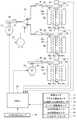
- FIG. 1 is an overall system diagram showing a drive system and a control system of a hybrid vehicle to which a driving force control device of Example 1 is applied.
- FIG. 3 is a control system configuration diagram illustrating a configuration of a transmission control system of the multi-stage gear transmission according to the first embodiment. It is a shift map schematic diagram which shows the view which switches a gear shift pattern in the multistage gear transmission of Example 1.
- FIG. 3 is an engagement operation table showing shift stages according to switching positions of three engagement clutches in the multi-stage gear transmission according to the first embodiment.
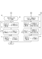
- 6 is a flowchart showing a flow of driving force control processing (steps S1 to S5, steps S10 to S15) executed in the first embodiment.
- Example 6 is a flowchart showing a flow of driving force control processing (steps S6 to S9, steps S16 to S19) executed in the first embodiment.
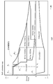
- Example 1 it is an example of the shift map used at the time of high SOC.
- Example 1 it is an example of the shift map used at the time of low SOC.
- It is explanatory drawing which shows the maximum value of the driving force in the HEV mode which changes according to an ascending gradient. It is a gradient setting map which sets the ascending gradient of the maximum value of the driving force in HEV mode at the time of low SOC.
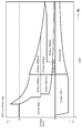
- Example 1 each of the vehicle speed, the vehicle G, the accelerator opening, the MG1 rotation speed, the ICE rotation speed, the MG1 torque, and the ICE torque when the mode is changed from EV to HEV with a change in the vehicle speed at high SOC.
- the vehicle speed, vehicle G, accelerator opening, MG1 rotation speed, ICE rotation speed, MG1 torque when the mode is changed from EV to HEV with a change in the required driving force of the driver at high SOC.
- Example 1 at low SOC, each of vehicle speed, vehicle G, accelerator opening, MG1 rotation speed, ICE rotation speed, MG1 torque, and ICE torque at the time of mode transition from EV to HEV with a change in vehicle speed It is a time chart which shows a characteristic. It is explanatory drawing which shows the movement locus
- Example 2 each vehicle speed, vehicle G, accelerator opening, MG1 rotation speed, ICE rotation speed, MG1 torque, and ICE torque when the mode is changed from EV to HEV with a change in vehicle speed at high SOC. It is a time chart which shows a characteristic. It is explanatory drawing which shows the movement locus
- the driving force control apparatus is a hybrid vehicle including an engine, two motor generators, and a multi-stage gear transmission having three engagement clutches as drive system components (an example of a hybrid vehicle). ).
- the configuration of the driving force control apparatus for a hybrid vehicle in the first embodiment will be described by being divided into “the overall system configuration”, “the shift control system configuration”, “the shift speed configuration”, and “the driving force control processing configuration”.
- FIG. 1 shows a drive system and a control system of a hybrid vehicle to which the driving force control apparatus of the first embodiment is applied.
- the overall system configuration of the first embodiment will be described below with reference to FIG.
- the drive system of the hybrid vehicle of the first embodiment is a multi-stage having an internal combustion engine ICE, a first motor generator MG1, a second motor generator MG2, and three engagement clutches C1, C2, C3.
- ICE is an abbreviation for “Internal-Combustion Engine”.
- the internal combustion engine ICE serves as a travel drive source for the hybrid vehicle, and is, for example, a gasoline engine or a diesel engine disposed in the front room of the vehicle with the crankshaft direction as the vehicle width direction.
- the internal combustion engine ICE is connected to the transmission case 10 of the multi-stage gear transmission 1, and the internal combustion engine output shaft is connected to the first shaft 11 of the multi-stage gear transmission 1.
- the internal combustion engine ICE basically starts with the second motor generator MG2 as a starter motor.
- the starter motor 2 is provided in preparation for a case where starting by the second motor generator MG2 using the high-power battery 3 cannot be ensured, such as at a very low temperature.
- the first motor generator MG1 (electric motor) is a three-phase AC permanent magnet synchronous motor that serves as a travel drive source for the hybrid vehicle during power running and serves as a generator during regeneration.
- the second motor generator MG2 is a motor that rotates the starter motor of the internal combustion engine ICE and the gear shaft of the multi-stage gear transmission 1 during power running, and a three-phase AC permanent magnet that becomes a generator when driven by the internal combustion engine ICE.
- Type synchronous motor The first motor generator MG1 and the second motor generator MG2 both use the high-power battery 3 as a common power source during power running.
- the high-power battery 3 is charged with the electric power generated by the first motor generator MG1 and the second motor generator MG2.
- the stator of first motor generator MG1 is fixed to the case of first motor generator MG1, and the case is fixed to transmission case 10 of multi-stage gear transmission 1.
- a first motor shaft that is integral with the rotor of first motor generator MG1 is connected to second shaft 12 of multi-stage gear transmission 1.
- the stator of the second motor generator MG2 is fixed to the case of the second motor generator MG2, and the case is fixed to the transmission case 10 of the multi-stage gear transmission 1.
- a second motor shaft integrated with the rotor of second motor generator MG2 is connected to sixth shaft 16 of multi-stage gear transmission 1.
- a first inverter 4 that converts direct current to three-phase alternating current during power running and converts three-phase alternating current to direct current during regeneration is connected to the stator coil of first motor generator MG1 via first AC harness 5.
- a second inverter 6 is connected to the stator coil of the second motor generator MG2 via a second AC harness 7 for converting direct current to three-phase alternating current during power running and converting three-phase alternating current to direct current during power generation.
- the high-power battery 3 is connected to the first inverter 4 and the second inverter 6 by a DC harness 8 via a junction box 9.
- the hybrid vehicle of Example 1 has "EV mode” and "HEV mode” as driving modes.
- the EV mode is a travel mode in which only the first motor generator MG1 is a travel drive source.
- the HEV mode is a travel mode in which the first motor generator MG1 and the internal combustion engine ICE are travel drive sources.
- the mode can be changed between the EV mode and the HEV mode based on the vehicle speed and the driver's required braking / driving force (Driving Force) that appears in the accelerator opening and the brake operation.
- Driving Force Driving Force
- the multi-stage gear transmission 1 is a constantly meshing transmission that has a plurality of gear pairs with different gear ratios and a shift element that switches the shift stages and realizes a plurality of shift stages.
- the multi-stage gear transmission 1 is disposed in a power transmission path from the internal combustion engine ICE, the first motor generator MG1, and the second motor generator MG2 to the drive wheels 19.
- This multi-stage gear transmission 1 is arranged in parallel with each other in a transmission case 10 and has six gear shafts 11 to 16 on which gears are provided and three engagement clutches C1 and C2 which are transmission elements for selecting a gear pair. , C3.
- a first shaft 11, a second shaft 12, a third shaft 13, a fourth shaft 14, a fifth shaft 15, and a sixth shaft 16 are provided.
- a first engagement clutch C1, a second engagement clutch C2, and a third engagement clutch C3 are provided.
- the first, second, and third engagement clutches C1, C2, and C3 are dog clutches that engage / release the meshing state at the time of shifting.
- the transmission case 10 is provided with an electric oil pump 20 that supplies lubricating oil to a bearing portion and a gear meshing portion in the case.
- the first shaft 11 is a shaft connected to the output shaft of the internal combustion engine ICE.
- a first gear 101, a second gear 102, and a third gear 103 are arranged on the first shaft 11 in order from the right side of FIG.
- the first gear 101 is provided integrally (including integrated fixing) with respect to the first shaft 11.
- the second gear 102 and the third gear 103 are idle gears in which bosses protruding in the axial direction are inserted into the outer periphery of the first shaft 11, and are connected to the first shaft 11 via the second engagement clutch C2. It is provided so that drive connection is possible.
- the second shaft 12 is a cylindrical shaft which is connected to the first motor shaft of the first motor generator MG1 and is coaxially arranged with the axis center aligned with the outer position of the first shaft 11.
- a fourth gear 104 and a fifth gear 105 are arranged on the second shaft 12 in order from the right side of FIG.
- the fourth gear 104 and the fifth gear 105 are provided integrally with the second shaft 12 (including integrated fixing).
- the third shaft 13 is a shaft that is disposed on the output side of the multi-stage gear transmission 1 and is supported at both ends by the transmission case 10.
- a sixth gear 106, a seventh gear 107, an eighth gear 108, a ninth gear 109, and a tenth gear 110 are arranged in this order from the right side in FIG.
- the sixth gear 106, the seventh gear 107, and the eighth gear 108 are provided integrally with the third shaft 13 (including integrated fixing).
- the ninth gear 109 and the tenth gear 110 are idle gears in which bosses protruding in the axial direction are inserted into the outer periphery of the third shaft 13, and are connected to the third shaft 13 via the third engagement clutch C3. It is provided so that drive connection is possible.
- the sixth gear 106 meshes with the second gear 102 provided on the first shaft 11, the seventh gear 107 meshes with the sixteenth gear 116 provided on the differential gear 17, and the eighth gear 108 meshes with the first shaft 11.
- the ninth gear 109 meshes with a fourth gear 104 provided on the second shaft 12, and the tenth gear 110 meshes with a fifth gear 105 provided on the second shaft 12.
- the fourth shaft 14 is a shaft whose both ends are supported by the transmission case 10.
- An eleventh gear 111, a twelfth gear 112, and a thirteenth gear 113 are arranged on the fourth shaft 14 in order from the right side of FIG.
- the eleventh gear 111 is provided integrally with the fourth shaft 14 (including integrated fixation).
- the twelfth gear 112 and the thirteenth gear 113 are idle gears in which bosses protruding in the axial direction are inserted into the outer periphery of the fourth shaft 14, and are connected to the fourth shaft 14 via the first engagement clutch C1. It is provided so that drive connection is possible.
- the eleventh gear 111 meshes with the first gear 101 provided on the first shaft 11
- the twelfth gear 112 meshes with the second gear 102 provided on the first shaft 11
- the thirteenth gear 113 communicates with the second shaft.
- the fifth shaft 15 is a shaft whose both ends are supported by the transmission case 10.
- a 14th gear 114 that meshes with an 11th gear 111 provided on the fourth shaft 14 is integrally provided (including integrated fixing) on the fifth shaft 15.
- the sixth shaft 16 is a shaft connected to the second motor shaft of the second motor generator MG2.
- a fifteenth gear 115 that meshes with a fourteenth gear 114 provided on the fifth shaft 15 is integrally provided (including integrated fixing) on the sixth shaft 16.
- the second motor generator MG2 and the internal combustion engine ICE are mechanically connected by a gear train including a 15th gear 115, a 14th gear 114, an 11th gear 111, and a first gear 101 that mesh with each other.
- this gear train becomes a reduction gear train that decelerates the second motor generator rotational speed (MG2 rotational speed), and is driven by the second motor generator MG2 by driving the internal combustion engine ICE.
- the speed increasing gear train increases the internal combustion engine speed (ICE speed).
- the first engagement clutch C1 is interposed between a twelfth gear 112 and a thirteenth gear 113 provided on the fourth shaft 14.
- the first engagement clutch C1 is a dog clutch that does not have a synchronization mechanism and is fastened by a meshing stroke in a rotationally synchronized state.
- the first engagement clutch C1 drives and connects the thirteenth gear 113 to the fourth shaft 14 when in the left engagement position (Left). Further, the first engagement clutch C1 releases both the twelfth gear 112 and the thirteenth gear 113 with respect to the fourth shaft 14 in the neutral position (N). Further, the first engagement clutch C1 drives and connects the twelfth gear 112 to the fourth shaft 14 at the right engagement position (Right).
- the second engagement clutch C 2 is interposed between the second gear 102 and the third gear 103 provided on the first shaft 11.
- the second engagement clutch C2 is a dog clutch that does not have a synchronization mechanism and is fastened by a meshing stroke in a rotationally synchronized state.
- the second engagement clutch C2 drive-couples the third gear 103 to the first shaft 11 when in the left-side engagement position (Left). Further, the second engagement clutch C2 releases both the second gear 102 and the third gear 103 with respect to the first shaft 11 when in the neutral position (N). Further, the second engagement clutch C2 drives and connects the second gear 102 to the first shaft 11 when in the right engagement position (Right).
- the third engagement clutch C3 is interposed between a ninth gear 109 and a tenth gear 110 provided on the third shaft 13.
- the third engagement clutch C3 is a dog clutch that does not have a synchronization mechanism and is fastened by a meshing stroke in a rotationally synchronized state.
- the third engagement clutch C3 drives and connects the tenth gear 110 to the third shaft 13 when in the left-side engagement position (Left). Further, the third engagement clutch C3 releases both the ninth gear 109 and the tenth gear 110 with respect to the third shaft 13 in the neutral position (N). Further, the third engagement clutch C3 drives and connects the ninth gear 109 to the third shaft 13 at the right engagement position (Right).
- a sixteenth gear 116 meshed with a seventh gear 107 provided integrally (including integral fixing) with the third shaft 13 of the multi-stage gear transmission 1 is left and right via the differential gear 17 and the left and right drive shafts 18. Are connected to the drive wheel 19.
- the vehicle control system of the first embodiment includes a hybrid control module 21, a motor control unit 22, a transmission control unit 23, and an engine control unit 24, as shown in FIG.
- the hybrid control module 21 (abbreviation: “HCM”) is an integrated control module having a function of appropriately managing the energy consumption of the entire vehicle.
- the hybrid control module 21 is connected to other control units (such as a motor control unit 22, a transmission control unit 23, and an engine control unit 24) via a CAN communication line 25 so that bidirectional information can be exchanged.
- CAN of the CAN communication line 25 is an abbreviation of “Controller Area Network”.
- the hybrid control module 21 controls the driving force transmitted to the drive wheels 19 in accordance with the driver's required driving force within the range of the maximum driving force that can be output by the traveling drive source (maximum output driving force). . That is, only the driving force output from the travel drive source (in the EV mode, only the output torque (MG1 torque) of the first motor generator MG1. In the HEV mode, the MG1 torque and the output torque (ICE torque) from the internal combustion engine ICE) Is controlled so as to satisfy the required driving force appearing in the accelerator opening. If the required driving force exceeds the maximum outputable driving force of the traveling drive source, the driving force output from the traveling drive source is set to the maximum value so that the required driving force is satisfied as much as possible. .
- the hybrid control module 21 of the first embodiment when the travel mode transitions from the EV mode to the HEV mode as the vehicle speed changes, sets the maximum value of the driving force to the drive wheels 19 in the HEV mode, Set the value to the same level as the maximum driving force that can be output in EV mode at the time of mode transition.
- the driving mode changes from EV mode to HEV mode due to changes in the driver's required driving force the maximum value of the driving force applied to the drive wheels 19 in the HEV mode can be output in the HEV mode. Set to driving force.
- the hybrid control module 21 corresponds to a driving force controller, and restricts the driving force to the driving wheels 19 in the HEV mode at the time of mode transition from the EV mode to the HEV mode accompanying a change in vehicle speed.
- the driving force to the driving wheel 19 in the HEV mode is not limited.
- the motor control unit 22 (abbreviation: “MCU”) performs power running control, regenerative (power generation) control, and the like of the first motor generator MG1 and the second motor generator MG2 according to control commands for the first inverter 4 and the second inverter 6. .
- Control modes for the first motor generator MG1 and the second motor generator MG2 include “torque control” and “rotational speed FB control”. In “torque control”, when the target motor torque to be shared with respect to the target driving force is determined during power running, control is performed so that the actual motor torque follows the target motor torque.
- the transmission control unit 23 (abbreviation: “TMCU”) outputs current commands to the first, second, and third electric actuators 31, 32, and 33 (see FIG. 2) based on predetermined input information. Shift control for switching the shift pattern of the gear transmission 1 is performed.
- the first, second, and third engagement clutches C1, C2, and C3 are selectively meshed and engaged / released, and a gear pair involved in power transmission is selected from a plurality of gear pairs.
- the first motor generator MG1 or the first motor generator MG1 or The rotation speed FB control (rotation synchronization control) of the second motor generator MG2 is also used.
- the engine control unit 24 (abbreviation: “ECU”) outputs a control command to the motor control unit 22, the ignition plug, the fuel injection actuator, and the like based on predetermined input information, thereby controlling the start-up of the internal combustion engine ICE and the internal combustion engine. Performs engine ICE stop control and fuel cut control.
- the multi-stage gear transmission 1 reduces clutch drag by employing the first, second, and third engagement clutches C1, C2, and C3 (dog clutches) that are engaged and engaged as transmission elements. To improve efficiency.
- the differential rotational speed of the clutch input / output is set to the first motor generator MG1 (third engagement). This is realized by synchronizing the rotation with the second motor generator MG2 (when the clutch C3 is engaged) or when the first and second engagement clutches C1 and C2 are engaged, and starting the meshing stroke when it is within the synchronization determination rotation speed range. .
- the transmission control system includes a first engagement clutch C1, a second engagement clutch C2, and a third engagement clutch C3 as engagement clutches.
- a first electric actuator 31 for C1, C2 shift operation a second electric actuator 32 for C1, C2 select operation, and a third electric actuator 33 for C3 shift operation are provided.
- a C1 / C2 select operation mechanism 40, a C1 shift operation mechanism 41, a C2 shift operation mechanism 42, and a C3 shift operation mechanism 43 are provided as shift mechanisms that convert the actuator operation into clutch engagement / release operation.
- a transmission control unit 23 is provided as a control means for the first electric actuator 31, the second electric actuator 32, and the third electric actuator 33.
- the first engagement clutch C1, the second engagement clutch C2, and the third engagement clutch C3 are respectively in a neutral position (N: release position), a left engagement position (Left: left clutch engagement engagement position), and a right engagement.
- Each of the engagement clutches C1, C2, C3 has the same configuration, and includes coupling sleeves 51, 52, 53, left dog clutch rings 54, 55, 56, and right dog clutch rings 57, 58, 59.
- the coupling sleeves 51, 52, and 53 are provided so as to be capable of stroke in the axial direction by spline coupling via hubs (not shown) fixed to the fourth shaft 14, the first shaft 11, and the third shaft 13.
- dog teeth 51a, 51b, 52a, 52b, 53a, 53b with flat top surfaces are provided on both sides. Further, fork grooves 51c, 52c, and 53c are provided at the circumferential center portions of the coupling sleeves 51, 52, and 53.
- the left dog clutch rings 54, 55, 56 are fixed to the bosses of the gears 113, 103, 110, which are the left idle gears of the engagement clutches C1, C2, C3, and are flat top surfaces facing the dog teeth 51a, 52a, 53a. Dog teeth 54a, 55a, and 56a.
- the right dog clutch rings 57, 58, 59 are fixed to the bosses of the respective gears 112, 102, 109 which are the right idle gears of the respective engagement clutches C1, C2, C3, and are flat top surfaces facing the dog teeth 51b, 52b, 53b. Dog teeth 57b, 58b, 59b.
- the C1 / C2 select operation mechanism 40 has a first position for selecting connection between the first electric actuator 31 and the C1 shift operation mechanism 41, and a second position for selecting connection between the first electric actuator 31 and the C2 shift operation mechanism 42. And a mechanism for selecting between.
- first position is selected, the shift rod 62 and the shift rod 64 of the first engagement clutch C1 are connected, and the shift rod 65 of the second engagement clutch C2 is locked at the neutral position.
- the second position is selected, the shift rod 62 and the shift rod 65 of the second engagement clutch C2 are connected, and the shift rod 64 of the first engagement clutch C1 is locked at the neutral position. That is, when a position for shifting one engagement clutch is selected from the first position and the second position, the other engagement clutch is locked and fixed at the neutral position.
- the C1 shift operation mechanism 41, the C2 shift operation mechanism 42, and the C3 shift operation mechanism 43 convert the rotation operation of the first and third electric actuators 31, 33 into the axial stroke operation of the coupling sleeves 51, 52, 53. It is a mechanism to convert.
- Each of the shift operation mechanisms 41, 42, 43 has the same configuration, and includes rotation links 61, 63, shift rods 62, 64, 65, 66, and shift forks 67, 68, 69.
- One end of each of the rotation links 61 and 63 is provided on the actuator shafts of the first and third electric actuators 31 and 33, and the other end is connected to the shift rod 64 (or the shift rod 65) and 66 so as to be relatively displaceable.
- the shift rods 64, 65, 66 are provided with springs 64 a, 65 a, 66 a at rod division positions, and can be expanded and contracted according to the magnitude and direction of the rod transmission force.
- One end of each of the shift forks 67, 68, 69 is fixed to the shift rods 64, 65, 66, and the other end is disposed in the fork grooves 51c, 52c, 53c of the coupling sleeves 51, 52, 53.
- the transmission control unit 23 includes a vehicle speed sensor 71, an accelerator opening sensor 72, a transmission output shaft rotational speed sensor 73, an engine rotational speed sensor 74, an MG1 rotational speed sensor 75, an MG2 rotational speed sensor 76, an inhibitor switch 77, a battery.
- a sensor signal or a switch signal from the SOC sensor 78 or the like is input.
- the transmission output shaft rotation speed sensor 73 is provided at the shaft end of the third shaft 13 and detects the shaft rotation speed of the third shaft 13.
- the transmission control unit 23 is a position servo control unit (for example, a position servo by PID control) that controls engagement and disengagement of the engagement clutches C1, C2, and C3 determined by the positions of the coupling sleeves 51, 52, and 53.
- This position servo control unit inputs sensor signals from the first sleeve position sensor 81, the second sleeve position sensor 82, and the third sleeve position sensor 83. Then, the sensor values of the sleeve position sensors 81, 82, 83 are read, and electric currents are supplied to the electric actuators 31, 32, 33 so that the positions of the coupling sleeves 51, 52, 53 become the fastening position or the releasing position by the meshing stroke. give. In other words, the idle gear is brought into the engagement state where the dog teeth welded to the coupling sleeves 51, 52, and 53 and the dog teeth welded to the idle gear are engaged with each other.
- the multi-stage gear transmission 1 does not have a power transmission element (rotational difference absorption element) capable of transmitting power while absorbing the rotational speed difference between the input side and the output side such as a friction clutch and a fluid coupling.
- a power transmission element rotational difference absorption element
- the ICE gear stage is reduced by assisting the internal combustion engine ICE with a motor to achieve compactness (EV gear stage: 1-2 speed, ICE gear stage: 1-4 speed).
- the hybrid vehicle of the first embodiment does not have the rotation difference absorbing element in the drive system, and the driving force output by the traveling drive source is It is transmitted directly to the drive wheel 19.
- the gear configuration of the multi-stage gear transmission 1 will be described with reference to FIGS. 3 and 4.
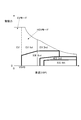
- the concept of the gear position is such that, in the starting region where the vehicle speed (VSP) is less than the predetermined vehicle speed VSP0, the multi-stage gear transmission 1 does not have a rotation difference absorbing element, so The stage is set and the motor starts only by the motor driving force. Then, in the travel region where the vehicle speed is equal to or higher than the predetermined vehicle speed VSP0, as shown in FIG. 3, a gear stage for “HEV mode” in which the engine driving force is assisted by the motor driving force is set according to the driving force request. Then, the concept of the shift stage is adopted in which the motor driving force and the engine driving force are used.
- the first motor generator MG1 and the internal combustion engine ICE are drivingly connected to the drive wheels 19, and the “HEV mode” is set. That is, the traveling mode of the hybrid vehicle is set according to the gear position of the multi-stage gear transmission 1.
- each gear stage will be described.
- the next gear position is set depending on the position of the first engagement clutch C1.
- “EV-ICEgen” if the first engagement clutch C1 is “Left”, “Neutral” if the first engagement clutch C1 is “N”, and “Night” if the first engagement clutch C1 is “Right”.
- EV-ICE3rd “.
- the shift stage of “EV-ICEgen” is selected during MG1 idle power generation with the first motor generator MG1 by the internal combustion engine ICE or double idle power generation in which MG2 idle power is added to MG1 idle power generation while the vehicle is stopped The gear position to be changed.
- the “Neutral” gear stage is a gear stage that is selected during MG2 idle power generation by the second motor generator MG2 by the internal combustion engine ICE while the vehicle is stopped.
- the shift stage “EV-ICE3rd” is a shift stage that is selected in the “ICE travel mode” in which the first motor generator MG1 is stopped and the internal combustion engine ICE performs the 3-speed ICE travel.
- the shift stage of “EV1st ICE-” is set in the “EV mode” in which the internal combustion engine ICE is stopped and traveled (regenerated) by the first motor generator MG1 or by the second motor generator MG2 by the internal combustion engine ICE. This is the gear position selected in the “series EV mode” in which the first motor generator MG1 performs the first speed EV running while generating power.
- the shift stage “EV-ICE2nd” is a shift stage that is selected in the “ICE travel mode” in which the first motor generator MG1 is stopped and the internal combustion engine ICE performs the 2-speed ICE travel.
- the shift stage of “EV2nd ICE-” is set in the “EV mode” in which the internal combustion engine ICE is stopped and traveled (regenerated) by the first motor generator MG1, or by the second motor generator MG2 by the internal combustion engine ICE. This is the gear position selected in the “series EV mode” in which the first motor generator MG1 performs the 2-speed EV running while generating power.
- the shift stage of “EV-ICE4th” is a shift stage that is selected in the “ICE travel mode” in which the first motor generator MG1 is stopped and the internal combustion engine ICE performs the 4-speed ICE travel.
- the multi-stage gear transmission 1 uses the multi-stage gear transmission 1 to remove all the gear stages from the "interlock gear stage (cross-hatching in FIG. 4)" and "the gear stage that cannot be selected by the shift mechanism (upward hatching in FIG. 4)".
- the gears that cannot be selected by the shift mechanism include “EV1.5 ICE2nd” in which the first engagement clutch C1 is “Left” and the second engagement clutch C2 is “Left”, “EV2.5 ICE4th” in which the clutch C1 is “Left” and the second engagement clutch C2 is “Right”.
- one first electric actuator 31 is a shift actuator that is also used for the two engagement clutches C1 and C2, and one engagement clutch by the C1 / C2 selection operation mechanism 40. Is due to being neutral locked.
- the “normally used shift speed” is the EV shift speed (EV1st ICE-, EV2nd ICE-), the ICE shift speed (EV- ICE2nd, EV- ICE3rd, EV- ICE4th) and the HEV mode. It is configured by adding “Neutral” to the combination gear position (EV1st ICE2nd, EV1st ICE3rd, EV2nd ICE2nd, EV2nd ICE3rd, EV2nd ICE4th).
- FIG. 5A and 5B are flowcharts illustrating the flow of the driving force control process executed in the first embodiment. Hereinafter, each step of FIG. 5A and FIG. 5B representing an example of the driving force control processing configuration will be described.
- step S1 it is determined whether or not the remaining charge (battery SOC) of the high-power battery 3 is greater than or equal to a preset SOC threshold value. If YES (battery SOC ⁇ SOC threshold), the process proceeds to step S2, and if NO (battery SOC ⁇ SOC threshold), the process proceeds to step S10.
- the battery SOC is detected by the battery SOC sensor 78.
- the “SOC threshold value” is a threshold value that determines whether or not to give priority to the charging operation of the high-power battery 3 over the driving force, and is arbitrarily set.
- step S2 following the determination that battery SOC ⁇ SOC threshold value in step S1, assuming that the battery SOC is sufficiently secured, a shift map used in motor control unit 22 is shown in FIG. And go to step S3.
- the “shift map” uses the vehicle speed (VSP) and the required braking / driving force (Driving force) as coordinate axes, and a selection area for a plurality of shift speeds constituting a normal-use shift speed group is assigned to the coordinate plane. It is a map.
- the motor control unit 22 determines the gear position of the multi-stage gear transmission 1 based on the position of the operating point on the shift map.
- the EV1st ICE- selection area is assigned to the low vehicle speed range from the start as the drive drive area by depressing the accelerator, and the EV2nd ICE-, Selection areas of “EV1st ICE2nd”, “EV1st ICE3rd”, “EV2nd ICE2nd”, “EV2nd ICE3rd”, and “EV2nd ICE4th” are allocated.
- a selection area of “EV1st ICE-” is assigned to the low vehicle speed range
- a selection area of “EV2nd ICE-” is assigned to the medium to high vehicle speed range.
- the line segment that divides each selection region indicates the maximum driving force (maximum drive force that can be output) that can be output by the traveling drive source in each selection region.
- the line segment that divides each selection region indicates the maximum braking force (maximum braking force that can be output) that the traveling drive source can output in each selection region.
- step S3 following the setting of the “high SOC shift map” in step S2, the accelerator opening is read, and the process proceeds to step S4.
- the accelerator opening is a parameter representing the driver's required driving force, and is detected by the accelerator opening sensor 72.
- step S4 following the reading of the accelerator opening in step S3, the vehicle speed is read, and the process proceeds to step S5.
- the vehicle speed is detected by a vehicle speed sensor 71.
- step S5 following the reading of the vehicle speed in step S4, it is determined whether or not a mode transition request from the EV mode to the HEV mode has been output. If YES (mode change is requested), the process proceeds to step S6. If NO (mode change is not requested), the process returns to step S3.
- the mode transition request from the EV mode to the HEV mode is determined by the operation point determined by the accelerator opening read in step S3 and the vehicle speed read in step S4 being “high SOC time” set in step S2. It is output by moving from the selection area of “EV1st ICE-” to the selection area of “EV1st ICE2nd” or the selection area of “EV1st ICE3rd” on the “shift map”.
- step S6 following the determination that there is a mode transition request in step S5, whether or not the mode transition determined to be requested in step S5 is based on a mode transition request accompanying a change (increase) in vehicle speed. Judging. If YES (change in vehicle speed: Auto Up), the process proceeds to step S7. If NO (change in required driving force: stepping down), the process proceeds to step S9.
- “mode change request accompanying change (increase) in vehicle speed” means that the vehicle speed increases even when the driver's required driving force is constant (including fluctuations in a predetermined range). The operating point moves from the selection area of “EV1st ICE-” to the selection area of “EV1st ICE2nd” or the selection area of “EV1st ICE3rd”. At this time, the driver keeps the accelerator opening substantially constant, and the shock sensitivity becomes high.
- step S7 following the determination of the mode transition request accompanying the change in vehicle speed in step S6, the maximum value of the driving force in the HEV mode (EV1st ICE2nd) is output in the EV mode (EV1st ICE-) at the time of mode transition.
- the value is set to a level equivalent to the maximum possible driving force (MAX driving force), and the process proceeds to step S8.
- the “driving force in the HEV mode” is a driving force transmitted from the traveling drive source (the first motor generator MG1 and the internal combustion engine ICE) to the drive wheels 19 in the HEV mode. That is, the total torque is obtained by adding the output torque (ICE torque) of the internal combustion engine ICE to the output torque (MG1 torque) of the first motor generator MG1.
- the “maximum driving force that can be output in the EV mode” is a driving force generated by the maximum torque that can be set in the traveling drive source (first motor generator MG1) in the EV mode.
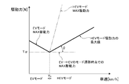
- an "output enable maximum driving force in the EV mode at the mode transition time” is the maximum driving force on the boundary line between the EV mode and the HEV mode, indicated by X 1 in FIG.
- “the maximum value of the driving force in the HEV mode is set to a value equivalent to the maximum driving force that can be output in the EV mode at the time of mode transition” means that the driving force in the HEV mode at the time of mode transition. It is to limit according to the maximum drive power that can be output in EV mode. As a result, even if the ICE torque is added to the MG1 torque due to the transition to the HEV mode, the upper limit of the driving force transmitted to the driving wheels 19 is limited.
- step S8 following the setting of the driving force in the HEV mode in step S7, the maximum outputable driving force (MAX driving force) in the HEV mode is the maximum outputable driving force (MAX driving force in the EV mode at the time of mode transition). ) Determine whether or not If YES (HEV mode MAX driving force ⁇ EV mode MAX driving force), the process proceeds to step S9. If NO (HEV mode MAX driving force> EV mode MAX driving force), the process returns to step S7.
- the “maximum driving force that can be output in the HEV mode” is a driving force generated by the maximum torque that can be set in the traveling drive source (the first motor generator MG1 and the internal combustion engine ICE) in the HEV mode.
- the “maximum output driving force in the HEV mode” varies depending on the vehicle speed, and the maximum output driving force that can be output varies depending on the vehicle speed even in the same “HEV mode”.
- step S9 following the determination of the mode transition request accompanying the change (increase) in the required driving force in step S6, or the determination of HEV mode MAX driving force ⁇ EV mode MAX driving force in step S8, the HEV mode
- the maximum value of the driving force at is set to the maximum outputable driving force (MAX driving force) in the HEV mode, and the process proceeds to the end.
- “mode change request accompanying change (increase) in required driving force” means that the required driving force of the driver increases even when the vehicle speed is constant (including fluctuations in a predetermined range).
- the operating point moves from the selection area of “EV1st ICE-” to the selection area of “EV1st ICE2nd” or the selection area of “EV1st ICE3rd”.
- the driver depresses the accelerator pedal, and the shock sensitivity is relatively low (acceptable mode transition shock is increased).
- HEV mode MAX driving force ⁇ EV mode MAX driving force the maximum driving force that can be set in the EV mode at the time of mode transition is the same level as the maximum driving torque that can be set by the traveling drive source. Means below the value. That is, in this step S9, the driver's required driving force is high and the shock sensitivity is low, or the driving force to the driving wheel 19 does not increase suddenly even if the maximum driving torque that can be set by the traveling drive source is output.
- the driving force in HEV mode is not limited to the maximum driving force that can be output.
- step S10 following the determination of SOC ⁇ SOC threshold value in step S1, a shift map used in the motor control unit 22 assuming that the battery SOC is not secured and charging should be preferentially performed is shown in FIG.
- the “low SOC shift map” shown is set, and the process proceeds to step S11.
- the “low SOC shift map” is compared to the “high SOC shift map” (Fig. 6), and the drive plane of the coordinate plane is “Series EV1st (series EV mode with“ EV1st ICE- ”). "EV1st ICE1st” is added, while “EV2nd ICE-” is omitted to reduce power consumption.
- the “Series EV1st” selection region is assigned to the low vehicle speed range from the start as the drive drive region by depressing the accelerator.
- the EV1st ICE1st, EV1st ICE2nd, and EV1st ICE3rd selection areas are assigned to the medium vehicle speed range, and the EV2nd ICE2nd, EV2nd ICE3rd, and EV2nd ICE4th selection areas are assigned to the high vehicle speed range. It is done.
- the "EV1st ICE- (EV2nd ICE-)" selection area is assigned to the low vehicle speed range and the "EV2nd ICE-" selection area is assigned to the high vehicle speed range.
- the line segment that divides each selection region indicates the maximum driving force (maximum drive force that can be output) that can be output by the traveling drive source in each selection region.
- the line segment that divides each selection region indicates the maximum braking force (maximum braking force that can be output) that the traveling drive source can output in each selection region.
- step S11 following the setting of the “low SOC shift map” in step S10, the accelerator opening is read, and the process proceeds to step S12.
- step S12 following the reading of the accelerator opening in step S11, the vehicle speed is read, and the process proceeds to step S13.
- step S13 following the reading of the vehicle speed in step S12, it is determined whether or not a mode transition request from the EV mode to the HEV mode has been output. If YES (mode change is requested), the process proceeds to step S14, and if NO (no mode change is requested), the process returns to step S11.
- the mode transition request from the EV mode to the HEV mode is determined by the operation point determined by the accelerator opening read in step S11 and the vehicle speed read in step S12 being “at low SOC”. Output when moving from the "Series EV1st" selection area to the "EV1st ICE1st" selection area on the "Shift Map".
- step S14 whether or not the mode transition determined to be requested in step S13 is based on a mode transition request accompanying a change (increase) in vehicle speed following the determination that there is a mode transition request in step S13. Judging. If YES (change in vehicle speed: Auto Up), the process proceeds to step S15. If NO (change in required driving force: stepping down), the process proceeds to step S19.
- “mode change request accompanying change (increase) in vehicle speed” means that the vehicle speed increases even when the driver's required driving force is constant (including fluctuations in a predetermined range). The operating point moves from the selected area of “Series EV1st” to the selected area of “EV1st ICE1st”.
- step S15 following the determination of the mode transition request accompanying the change in vehicle speed in step S14, the battery SOC is read, and the process proceeds to step S16.
- the battery SOC is detected by the battery SOC sensor 78.
- step S16 following the reading of the battery SOC in step S15, the driving force increasing gradient ⁇ in the HEV mode is set based on the read battery SOC, and the process proceeds to step S17.
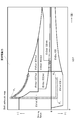
- the “driving gradient ⁇ of the driving force in the HEV mode” means the maximum output driving force (MAX) at the time of mode transition from the EV mode to the HEV mode (at the time of the vehicle speed V 0 ).
- the driving force is a gradient when the driving force in the HEV mode increases with an increase in the vehicle speed with reference to “T ⁇ ”. That is, when the maximum value of the driving force in the HEV mode changes on the line segment that becomes “T ⁇ ” as the vehicle speed increases, the rising gradient ⁇ is set to zero.
- the ascending gradient ⁇ is set based on the battery SOC and the map shown in FIG. 8B.
- the maximum value of the driving force in the HEV mode is set to the maximum outputable driving force (MAX driving force) in the HEV mode.
- step S17 following the setting of the rising gradient ⁇ in step S16, the maximum driving force in the HEV mode (EV1st ICE1st) is set to the maximum output driving force (MAX driving) in the EV mode (Series EV1st) at the time of mode transition. Force) to a value that changes (increases) at the rising gradient ⁇ set in step S16 in accordance with the increase in vehicle speed, and proceeds to step S18.
- the "output enable maximum driving force in the EV mode at the mode transition time” is the maximum driving force on the boundary line between the EV mode and the HEV mode, indicated by X 2 in FIG.
- the maximum value of the driving force in the HEV mode is set to a value that increases with the rising gradient ⁇ from the maximum outputable driving force in the EV mode at the time of mode transition” means that the driving force in the HEV mode is The limitation amount is varied based on the battery SOC while being limited according to the maximum output possible driving force in the EV mode at the time of transition. As a result, the upper limit of the driving force transmitted to the driving wheel 19 in the HEV mode increases as the battery SOC decreases.
- step S18 following the setting of the driving force in the HEV mode in step S17, the maximum outputable driving force (MAX driving force) in the HEV mode is calculated from the maximum outputable driving force in the EV mode at the time of mode transition. It is determined whether or not the value has changed to a value that changes with the rising gradient ⁇ according to the rising. If YES (HEV mode MAX driving force ⁇ value changing with rising gradient ⁇ ), the process proceeds to step S19. If NO (HEV mode MAX driving force> value changing with rising gradient ⁇ ), the process returns to step S17.
- MAX driving force MAX driving force
- step S19 following the determination of the mode transition request accompanying the change (increase) of the required driving force in step S14, or the determination of the HEV mode MAX driving force in step S18 ⁇ the value changing with the rising gradient ⁇ , Set the maximum value of the driving force in the HEV mode to the maximum outputable driving force (MAX driving force) in the HEV mode, and proceed to the end.
- the rotation difference absorbing element is a power transmission element capable of transmitting torque even when a rotation difference is generated between the input side rotation element and the output side rotation element, such as a friction clutch or a torque converter.
- the fastening torque is gradually increased in a state where the output side rotating element is slid with respect to the input side rotating element, and the fluctuation of the driving force transmitted to the input side rotating element is absorbed. be able to.
- the driver's shock sensitivity to the mode transition shock (ease of feeling the shock) varies depending on the driving situation. That is, at the time of mode transition from the EV mode to the HEV mode due to an increase in the driver's required driving force, the driver wants an increase in driving force. Therefore, the shock sensitivity is relatively low, and the mode transition shock that can be tolerated (not feeling uncomfortable) increases.
- the shock sensitivity is relatively high, and even a slight shock (driving force fluctuation) tends to feel uncomfortable.
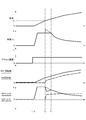
- FIG. 9 shows vehicle speed, vehicle G, accelerator opening, MG1 rotation speed, ICE rotation speed, MG1 torque, when the mode is changed from EV to HEV with a change in vehicle speed at high SOC in the first embodiment. It is a time chart which shows each characteristic of ICE torque.
- Vehicle G is an acceleration acting on the vehicle body and is a value indicating the driving force transmitted from the driving source to the driving wheels 19.
- MG1 rotation speed is the output rotation speed of the first motor generator MG1.
- the “ICE rotational speed” is the output rotational speed of the internal combustion engine ICE.
- MG1 torque is the output torque of the first motor generator MG1.
- ICE torque is the output torque of the internal combustion engine ICE.
- vehicle G the plus side indicates acceleration (driving force), and the minus side indicates deceleration (braking force).
- MG1 torque the plus side indicates drive torque, and the minus side indicates regenerative torque.
- ICE torque the plus side indicates drive torque, and the minus side indicates power generation torque (torque for generating power by the second motor generator MG2).
- a stopped state in which both the first motor generator MG1 and the internal combustion engine ICE are stopped in a state where the battery SOC is relatively high (above the SOC threshold).
- the process proceeds from step S1 to step S2, and the “high SOC shift map” shown in FIG. 6 is set as the shift map.
- the process proceeds from step S3 to step S4 to step S5.
- Time t 1 in the previously shown in FIG. 9, both the accelerator opening and the vehicle speed is zero. For this reason, as shown in FIG.
- the operating point on the shift map exists at the position P, and in the multi-stage gear transmission 1, all of the first, second, and third engagement clutches C1, C2, C3 are “ “Neutral”, or “EV1st ICE-” gear position where the first and second engagement clutches C1 and C2 are “Neutral” and the third engagement clutch C3 is “Left”. Further, since the operating point does not move, a mode transition request from the EV mode to the HEV mode is not output, and the flow of step S3 ⁇ step S4 ⁇ step S5 is repeated.
- Accelerator pedal is depressed at time t 1, the accelerator opening increases. At this time, the required driving force of the driver appearing at the accelerator opening is set to the magnitude indicated by the broken line in FIG.
- the accelerator pedal is depressed, by the driver's required driving force is generated, the operating point on the shift map is moved to the position P 1 from the position P.
- the gear position of the multi-stage gear transmission 1 is set to “EV1st ICE-”
- the third engagement clutch C3 is set to “Left”
- the first motor generator MG1 is driven.
- time t MG1 torque is generated from the second time point, MG1 rotational speed rises.
- acceleration is applied to the vehicle body to generate the vehicle G, and the vehicle speed starts to increase.
- the vehicle G has a size proportional to the MG1 torque.
- the vehicle speed is a value proportional to the MG1 rotation speed.
- the driving force transmission path at this time is, as shown in FIG. 11A, from the first motor generator MG1 ⁇ the second shaft 12 ⁇ the third engagement clutch C3 ⁇ the third shaft 13 ⁇ the drive shaft 18 ⁇ the drive wheel 19. Connected. That is, only MG1 torque from first motor generator MG1 is transmitted to drive wheel 19.
- the operating point on the shift map shown in FIG. 10 moves with the increase in the vehicle speed.
- the accelerator opening is maintained at a constant value, and the required driving force of the driver is also maintained at the value indicated by the broken line. Therefore, the output maximum possible driving force to the required driving force is smaller than the operating point, as indicated by the arrows in FIG. 10, according the position P 1 to the vehicle speed increases, indicating the available output maximum driving force It moves to the right on the line segment.
- the driving force transmission path at this time is connected to the first motor generator MG1 ⁇ the second shaft 12 ⁇ the third engagement clutch C3 ⁇ the third shaft 13 ⁇ the drive shaft 18 ⁇ the drive wheel 19.
- the path is connected to the internal combustion engine ICE ⁇ the first shaft 11 ⁇ the second engagement clutch C2 ⁇ the third shaft 13 ⁇ the drive shaft 18 ⁇ the drive wheel 19. That is, MG1 torque from the first motor generator MG1 and ICE torque from the internal combustion engine ICE are transmitted to the drive wheels 19.
- step S5 the mode change request at time t 3 moment whether or not associated with a change in the vehicle speed is determined.
- the accelerator opening maintains a constant value from the time t 1 point.
- the vehicle speed continues to increase from the time t 2 time. That is, the mode change request at this time t 3 time points are those associated with a change in the vehicle speed. Therefore, the process proceeds from step S6 to step S7, and the maximum value of the driving force in the HEV mode is set to a value equivalent to the maximum outputable driving force in the EV mode (EV1st ICE-) at the time of mode transition.
- the maximum driving force that can be output by the traveling drive source is the same as that in “EV1st ICE-” that is the EV mode.
- the ICE torque is added to the MG1 torque, which greatly increases.
- the maximum driving force value in the HEV mode is set to the same level as the maximum driving force that can be output in the EV mode (EV1st ICE-) at the time of mode transition.
- the driving force transmitted to the driving wheel 19 is limited. That is, regardless of the required driving force, on the shift map shown in FIG. 10, the driving point that has entered the “EV1st ICE2nd” selection region moves to the right on the line indicated by the arrow as the vehicle speed increases. Will go.
- step S8 the process proceeds from step S8 to step S9, and the maximum value of the driving force in the HEV mode is set to the maximum outputable driving force in the HEV mode. That is, in the time t 4 later, the operating point, as indicated by the arrows in FIG. 10, with an increase in vehicle speed, it moves on the line segment showing the output maximum possible driving force from the position P 2 to the right and Become. As a result, the MG1 torque suppression control can be terminated while suppressing a significant fluctuation of the vehicle G, which is the driving force transmitted to the drive wheels 19.
- FIG. 12 shows the vehicle speed, vehicle G, accelerator opening, MG1 rotation speed, ICE rotation speed, MG1 when the mode is changed from EV to HEV with a change in the required driving force at high SOC in the first embodiment. It is a time chart which shows each characteristic of torque and ICE torque.
- the high SOC driving force non-limiting action will be described based on the flowchart shown in FIGS. 5A and 5B and the time chart shown in FIG. “Vehicle G”, “MG1 rotation speed”, “ICE rotation speed”, “MG1 torque”, and “ICE torque” are the same as those in FIG.
- a state is considered in which the battery SOC is relatively high (above the SOC threshold value) and coast regeneration is being performed by an accelerator release operation.
- the process proceeds from step S1 to step S2, and the “high SOC shift map” shown in FIG. 6 is selected as the shift map.
- the process proceeds from step S3 to step S4 to step S5.
- Time t 11 and earlier shown in FIG. 12 the vehicle speed accelerator pedal of what is occurring is not stepped on. Therefore, as shown in FIG.
- the operating point on the shift map is present at the position P 3, the shift stages of the multi-stage gear transmission 1 is set to "EV1st ICE" third engagement clutch C3 is "Left "Is set. Further, the first motor generator MG1 is regenerated. As the first motor generator MG1 regenerates, a regenerative braking force is generated, a deceleration acts on the vehicle body, and the vehicle speed decreases. That is, with a decrease in the vehicle speed, the operating point on the shift map along the arrows shown in FIG. 13, moves to progressively left from the position P 3. Since the operating point moves within the selection area of “EV1st ICE”, the mode transition request from the EV mode to the HEV mode is not output, and the flow of step S3 ⁇ step S4 ⁇ step S5 is repeated.
- step S5 the mode change request at time t 11 the time is whether or not associated with a change in the vehicle speed is determined.
- accelerator opening increases at time t 11 the time, mode change request at this time t 11 time, and that with a change in the driver's required driving force. Therefore, the process proceeds from step S6 to step S9, and the maximum value of the driving force in the HEV mode is set to the maximum outputable driving force (MAX driving force) in the HEV mode.
- MAX driving force maximum outputable driving force
- the operating point enters the selected area of the "EV1st ICE2nd", as indicated by the arrows in FIG. 13, moves on the line segment showing the output enable maximum driving force to the position P 5.
- the vehicle G is further increased.
- the driving force transmitted to the driving wheel 19 can be increased by mode transition from the EV mode to the HEV mode, and a quick response can be made to the driver's required driving force.
- the maximum value of the driving force in the HEV mode is not limited, the vehicle G varies with the mode transition.
- the shock sensitivity is relatively low and, as shown in FIG. 12, the first motor generator MG1 changes from the regenerative state to the driving state. It is in a rising state. Therefore, it is difficult for the driver to feel uncomfortable with the mode transition shock, and the mode transition shock can be allowed.
- the maximum value of the driving force in the HEV mode is limited to, for example, the maximum driving force that can be output in the EV mode (EV1st ICE-) at the time of mode transition, the driving wheel will change when the mode transitions from the EV mode to the HEV mode.
- the vehicle G that is the driving force transmitted to 19 is suppressed from rising. Therefore, although the mode transition shock is reduced, the required driving force of the driver and the driving force transmitted to the drive wheels 19 are greatly deviated. For this reason, although the driver is depressing the accelerator pedal, the driver cannot feel an increase in driving force and feels uncomfortable.
- FIG. 14 shows vehicle speed, vehicle G, accelerator opening, MG1 rotation speed, ICE rotation speed, MG1 torque, when the mode is changed from EV to HEV with a change in vehicle speed at low SOC in the first embodiment. It is a time chart which shows each characteristic of ICE torque.
- Vehicle G shows vehicle speed, vehicle G, accelerator opening, MG1 rotation speed, ICE rotation speed, MG1 torque, when the mode is changed from EV to HEV with a change in vehicle speed at low SOC in the first embodiment.
- It is a time chart which shows each characteristic of ICE torque.
- step S11 ⁇ step S12 ⁇ step S13 is repeated.
- the accelerator pedal is depressed, by the driver's required driving force is generated, the operating point on the shift map is moved to the position P 7 from the position P 6.
- the gear position of the multi-stage gear transmission 1 is set to “Series EV1st (series EV mode with“ EV1st ICE- ”)”, and the third engagement clutch C3 is set to “Left”.
- the first motor generator MG1 is driven, and the internal combustion engine ICE is driven by the second motor generator MG2, and the second motor generator MG2 is generated.
- the rotational speed of the first motor generator MG1 increases.
- the second motor generator MG2 since the second motor generator MG2 is caused to generate electric power, power generation torque of the internal combustion engine ICE is generated, and the rotational speed of the internal combustion engine ICE increases. As a result, acceleration is applied to the vehicle body to generate the vehicle G, and the vehicle speed starts to increase.
- the vehicle G has a size proportional to the MG1 torque.
- the vehicle speed is a value proportional to the MG1 rotation speed.
- the driving force transmission path at this time is as follows: first motor generator MG1 ⁇ second shaft 12 ⁇ third engagement clutch C3 ⁇ third shaft 13 ⁇ drive shaft 18 ⁇ drive wheel 19. Connected.
- the power generation torque output from the internal combustion engine ICE is: internal combustion engine ICE ⁇ first shaft 11 ⁇ fourth shaft 14 ⁇ fifth shaft 15 ⁇ sixth shaft 16 ⁇ second Connected to motor generator MG2.
- the driving point on the shift map shown in FIG. 15 also moves as the vehicle speed increases.
- the accelerator opening is maintained at a constant value, and the required driving force of the driver is also maintained at the value indicated by the broken line. Therefore, the output maximum possible driving force to the required driving force is smaller than the operating point, as indicated by the arrows in FIG. 15, in response to an increase in vehicle speed, indicating the available output maximum driving force from the position P 7 It moves to the right on the line segment.
- the driving force transmission path at this time is connected to the first motor generator MG1, the second shaft 12, the third engagement clutch C3, the third shaft 13, the drive shaft 18, and the drive wheels 19.
- the path is connected to the internal combustion engine ICE ⁇ the first shaft 11 ⁇ the fourth shaft 14 ⁇ the first engagement clutch C1 ⁇ the second shaft 12 ⁇ the third engagement clutch C3 ⁇ the third shaft 13 ⁇ the drive shaft 18 ⁇ the drive wheel 19.
- MG1 torque from the first motor generator MG1 and ICE torque from the internal combustion engine ICE are transmitted to the drive wheels 19.
- step S13 mode change request at time t 23 the time is whether or not associated with a change in the vehicle speed is determined.
- the accelerator opening maintains a constant value from the time t 21 time.
- the vehicle speed continues to increase from the time t 21 time. That is, the mode change request at this time t 23 time, is accompanied with a change in the vehicle speed. Therefore, the process proceeds from step S14 to step S15 to step S16, and the driving force increase gradient ⁇ in the HEV mode is set based on the read battery SOC and the map shown in FIG. 8B.
- step S17 the maximum value of the driving force in the HEV mode (EV1st ICE1st) increases from the maximum outputable driving force in the EV mode (Series EV1st) at the time of mode transition as the vehicle speed increases. Is set to a value that changes (increases).
- the maximum value of the driving force in the HEV mode is not limited (indicated by a broken line in FIG. 14)
- the increase of the vehicle G is suppressed, and the vehicle G when the mode transition from the EV mode to the HEV mode is performed. Variations can be suppressed.
- the operating point enters the selected area of the "EV1st ICE1st 'from position P 8 is regardless of the output maximum possible driving force of the" EV1st ICE1st ", with increasing vehicle speed, the EV mode in the mode transition time From the maximum output possible driving force (“T ⁇ ” in FIG. 15), the line segment indicated by the arrow shown in FIG. 15 moves to the right. Therefore, an increase in driving force at the time of mode transition can be suppressed and fluctuations in the vehicle G can be suppressed.
- the rising gradient ⁇ is set according to the battery SOC, and the lower the battery SOC, the larger the rising gradient ⁇ is set (see FIG. 8B). That is, the lower the battery SOC, the smaller the amount of suppression of the maximum value of the driving force in the HEV mode.
- the output torque (ICE torque) of the internal combustion engine ICE is controlled as shown in FIG. Suppress. Therefore, the ICE torque increases as the battery SOC decreases, and the consumption of the high-power battery 3 can be suppressed.
- a driving force controller (hybrid control module 21) that controls the driving force to the driving wheels 19 in accordance with the required driving force within the range of the maximum driving force that can be output by the travel drive source;
- the driving force controller determines the driving force applied to the driving wheels 19 in the HEV mode when the mode transitions from the EV mode to the HEV mode as the vehicle speed changes.
- the driving is limited according to the maximum driving force that can be output in the EV mode. For this reason, in a hybrid vehicle having no rotation difference absorbing element, it is possible to make it difficult to feel a mode transition shock at the time of mode transition from the EV mode to the HEV mode even when the driver has a high shock sensitivity.
- the driving force controller (hybrid control module 21) is configured to switch the driving wheel 19 in the HEV mode when the mode transitions from the EV mode to the HEV mode with a change in the driving force required by the driver.
- the driving force is not limited to the maximum driving force that can be output in the HEV mode. For this reason, in addition to the effect of (1), when the driver's required driving force increases, the driving force transmitted to the drive wheels 19 can be increased, and the driver's required driving force can be quickly responded. Can do.
- the driving force controller (hybrid control module 21) is a battery (strong electric power) that supplies electric power to the electric motor (first motor generator MG1) when limiting the driving force to the driving wheels 19 in the HEV mode.
- the remaining charge (battery SOC) of the battery 3) is lower, the increase gradient ⁇ of the driving force to the driving wheel 19 in the HEV mode is set to a larger value. For this reason, in addition to the effect of (1) or (2), when the battery SOC is low, the ICE torque is increased, and consumption of the high-power battery 3 can be suppressed.
- the second embodiment is an example in which, in the “high SOC shift map”, when the mode is changed from the EV mode to the HEV mode, the maximum outputable driving force in the EV mode is lower than the peak time.
- the shift map shown in FIG. 17 is used as the “high SOC shift map” set when the battery SOC is relatively high.
- the allocation of each selected area is equivalent to the “high SOC shift map” (see FIG. 6) in the first embodiment, but the EV mode “EV1st ICE”.
- the maximum output power that can be output in “-” is different.
- the maximum outputable driving force is a constant value from the vehicle speed zero to the vehicle speed V 0 in which the mode transition is made from the HEV mode.
- the vehicle speed zero to speed V 2 is output maximum possible driving force has a constant value, the vehicle speed as a boundary vehicle speed V 2 As the output increases, the maximum driving force that can be output gradually decreases.
- the vehicle speed V 3 to mode transitions to the HEV mode output the maximum possible driving force of the EV mode is lower than the peak. Further, in the HEV mode (EV1st ICE2nd), the maximum output power that can be output is greatly increased by the amount of output torque of the internal combustion engine ICE.
- FIG. 18 shows vehicle speed, vehicle G, accelerator opening, MG1 rotation speed, ICE rotation speed, MG1 torque, when the mode is changed from EV to HEV with a change in the vehicle speed at high SOC in the second embodiment. It is a time chart which shows each characteristic of ICE torque.
- Vehicle G “MG1 rotation speed”, “ICE rotation speed”, “MG1 torque”, and “ICE torque” are the same as those in FIG.
- the accelerator pedal is depressed, by the driver's required driving force is generated, the operating point on the shift map is moved to the position P 10 from the position P 9.
- the gear stage of the multi-stage gear transmission 1 is set to “EV1st ICE-” and the first motor generator MG1 is driven.
- the output torque of the first motor generator MG1 is generated from the time t 32 when the rotational speed of the first motor generator MG1 increases.
- acceleration is applied to the vehicle body to generate the vehicle G, and the vehicle speed starts to increase.
- the driving point on the shift map shown in FIG. 19 also moves.
- the accelerator opening is maintained at a constant value, and the required driving force of the driver is also maintained at the value indicated by the broken line. Therefore, the operating point, as indicated by the arrows in FIG. 19, according the position P 10 to the vehicle speed increases, moves on the segment to the right showing the output maximum possible driving force.
- the required driving force is constant, while the vehicle speed continues to increase. Therefore, as a mode change request at time t 34 the time is accompanied with a change in the vehicle speed, the maximum value of the driving force in the HEV mode, the output enable maximum driving force in the EV mode (EV1st ICE-) at the mode transition time Is set to a value equivalent to. That is, the output enable maximum driving force in the EV mode (EV1st ICE-) is decreased from the time t 33 time, and has a T beta at time t 34 time. Therefore, the maximum value of the driving force in the HEV mode is set to “T ⁇ ” which is lower than the peak of the maximum outputable driving force in the EV mode.
- the driving force transmitted to the driving wheel 19 is limited to “T ⁇ ”, and the driving point that has entered the selected region of “EV1st ICE2nd” on the shift map shown in FIG. , so that moves on the line segment indicated by arrow with the position P 12 to the increase in vehicle speed.
- the first motor generator MG1 reduces the MG1 torque having the same magnitude as the generated ICE torque and suppresses the increase of the vehicle G. To do. Thereby, the fluctuation
- the EV mode in the mode transition time (EV1st ICE-) It will be less than the maximum possible driving force.
- the operating point on the shift map shown in FIG. 19 moves to the position P 13.
- the maximum value of the driving force in the HEV mode is set to the maximum outputable driving force in the HEV mode. That is, in the time t 35 after the operating point, as indicated by the arrows in FIG. 19, with an increase in vehicle speed, it moves on the line segment showing the output maximum possible driving force from the position P 13 to the right and become.
- the MG1 torque suppression control can be terminated while suppressing a significant fluctuation of the vehicle G, which is the driving force transmitted to the drive wheels 19.
- the maximum value of the driving force to the driving wheel 19 is controlled by suppressing the MG1 torque as much as the ICE torque is added.
- the limitation of the maximum driving force value in the HEV mode is limited in the HEV mode. Continue until the maximum output possible driving force is less than or equal to the maximum output possible driving force in EV mode (EV1st ICE-) at the time of mode transition. Therefore, the MG1 torque suppression control can be ended while suppressing a large fluctuation of the vehicle G that is the driving force transmitted to the drive wheels 19.
- the maximum outputable driving force in the HEV mode is the value at the time of mode transition.
- the maximum driving force to the driving wheel 19 in the HEV mode is the maximum driving force that can be output in the EV mode at the time of mode transition until a value equivalent to the maximum driving force that can be output in the EV mode is reached. It was set as the structure restrict
- Example 1 As mentioned above, although the driving force control apparatus of the hybrid vehicle of this invention has been demonstrated based on Example 1 and Example 2, it is not restricted to these Examples about a concrete structure, Claim of Claim Design changes and additions are allowed without departing from the spirit of the invention according to each claim.
- the MG1 torque that is the output torque of the first motor generator MG1 is reduced by the ICE torque. Not limited to this.
- the vehicle changed from the EV mode to the HEV mode at time t 41 as the vehicle speed changed.
- the ICE torque which is the output torque of the internal combustion engine ICE, is suppressed more than when it is output to the maximum (shown by a broken line).
- FIG. 21 in the case of using the "high SOC during shift map" in Example 2 (see FIG.
- the ICE torque which is the output torque of the internal combustion engine ICE, is suppressed more than when the maximum output is shown (indicated by a broken line).
- the ICE torque may be suppressed when the change (increase) in the vehicle speed G indicating the driving force to the drive wheels 19 is suppressed.
- the vehicle speed G indicating the driving force to the driving wheel 19 is controlled (suppressed) by both the MG1 torque and the ICE torque.
- the change (increase) may be suppressed.
- the driving force control device of the present invention is a multi-stage gear having one internal combustion engine (engine), two motor generators, and three engagement clutches as drive system components.
- engine internal combustion engine
- motor generators two motor generators
- three engagement clutches as drive system components.
- An example of application to a hybrid vehicle including a transmission is shown.
- the driving force control device of the present invention can be applied to, for example, a hybrid vehicle equipped with one engine and one motor.
Abstract
Description
一方、ドライバーの要求駆動力が変化していなくても、車速が変化したことでEVモードからHEVモードへとモード遷移することがある。このときには、ドライバーのショック感度が高く、違和感を感じやすくなっている。
そして、この駆動力コントローラは、車速の変化に伴ってEVモードからHEVモードへとモード遷移するとき、HEVモードでの駆動輪への駆動力を、モード遷移時点におけるEVモードでの出力可能最大駆動力に応じて制限する。
そのため、HEVモードへとモード遷移したことで、駆動輪に伝達される駆動力として、電動機の駆動力に内燃機関の駆動力が加えられても、駆動輪へ伝達される駆動力の急上昇を抑制できる。これにより、モード遷移ショックが抑えられ、車速が変化に伴うEVモードからHEVモードへのモード遷移であるために、ドライバーのショック感度が高くても、違和感を感じることが防止できる。
すなわち、回転差吸収要素を持たないハイブリッド車両において、ドライバーのショック感度が高い場合でも、EVモードからHEVモードへのモード遷移時のモード遷移ショックを感じにくくすることができる。
まず、構成を説明する。
実施例1の駆動力制御装置は、駆動系構成要素として、1つのエンジンと、2つのモータジェネレータと、3つの係合クラッチを有する多段歯車変速機と、を備えたハイブリッド車両(ハイブリッド車両の一例)に適用したものである。以下、実施例1におけるハイブリッド車両の駆動力制御装置の構成を、「全体システム構成」、「変速制御系構成」、「変速段構成」、「駆動力制御処理構成」に分けて説明する。
図1は、実施例1の駆動力制御装置が適用されたハイブリッド車両の駆動系及び制御系を示す。以下、図1に基づき、実施例1の全体システム構成を説明する。
第1モータジェネレータMG1のステータは、第1モータジェネレータMG1のケースに固定され、そのケースが多段歯車変速機1の変速機ケース10に固定される。そして、第1モータジェネレータMG1のロータに一体の第1モータ軸が、多段歯車変速機1の第2軸12に接続される。第2モータジェネレータMG2のステータは、第2モータジェネレータMG2のケースに固定され、そのケースが多段歯車変速機1の変速機ケース10に固定される。そして、第2モータジェネレータMG2のロータに一体の第2モータ軸が、多段歯車変速機1の第6軸16に接続される。第1モータジェネレータMG1のステータコイルには、力行時に直流を三相交流に変換し、回生時に三相交流を直流に変換する第1インバータ4が、第1ACハーネス5を介して接続される。第2モータジェネレータMG2のステータコイルには、力行時に直流を三相交流に変換し、発電時に三相交流を直流に変換する第2インバータ6が、第2ACハーネス7を介して接続される。
強電バッテリ3と第1インバータ4及び第2インバータ6は、ジャンクションボックス9を介してDCハーネス8により接続される。
この多段歯車変速機1は、変速機ケース10内に互いに平行に配置され、歯車が設けられる6つの歯車軸11~16と、歯車対を選択する変速要素である3つの係合クラッチC1,C2,C3と、を備える。歯車軸としては、第1軸11と、第2軸12と、第3軸13と、第4軸14と、第5軸15と、第6軸16が設けられる。係合クラッチとしては、第1係合クラッチC1と、第2係合クラッチC2と、第3係合クラッチC3が設けられる。ここで、第1,第2,第3係合クラッチC1,C2,C3は、変速時に噛み合い状態を締結/解放するドグクラッチである。なお、変速機ケース10には、ケース内の軸受け部分や歯車の噛み合い部分に潤滑オイルを供給する電動オイルポンプ20が付設されている。
そして、第6歯車106は第1軸11に設けられた第2歯車102に噛み合い、第7歯車107はデファレンシャル歯車17に設けられた第16歯車116と噛み合い、第8歯車108は第1軸11に設けられた第3歯車103に噛み合う。第9歯車109は第2軸12に設けられた第4歯車104に噛み合い、第10歯車110は第2軸12に設けられた第5歯車105に噛み合う。
そして、第11歯車111は第1軸11に設けられた第1歯車101に噛み合い、第12歯車112は第1軸11に設けられた第2歯車102と噛み合い、第13歯車113は第2軸12に設けられた第4歯車104と噛み合う。
すなわち、このハイブリッドコントロールモジュール21は、駆動力コントローラに相当するものであり、車速変化に伴うEVモードからHEVモードへのモード遷移時、HEVモードでの駆動輪19への駆動力を制限し、要求駆動力変化に伴うEVモードからHEVモードへのモード遷移時、HEVモードでの駆動輪19への駆動力を制限しない。
「トルク制御」では、力行時、目標駆動力に対して分担する目標モータトルクが決まると、実モータトルクを目標モータトルクに追従させる制御を行う。「回転数FB制御」では、走行中に係合クラッチC1,C2,C3の何れかを噛み合い締結する変速要求があると、クラッチ入出力回転数を回転同期させる目標モータ回転数を決め、実モータ回転数を目標モータ回転数に収束させるようにFBトルクを出力する制御を行う。
実施例1の多段歯車変速機1は、変速要素として、噛み合い締結による第1,第2,第3係合クラッチC1,C2,C3(ドグクラッチ)を採用することにより、クラッチの引き摺りを低減することで効率化を図る。そして、第1,第2,第3係合クラッチC1,C2,C3のいずれかを噛み合い締結させる変速要求があると、クラッチ入出力の差回転数を、第1モータジェネレータMG1(第3係合クラッチC3の締結時)又は第2モータジェネレータMG2(第1,第2係合クラッチC1,C2の締結時)により回転同期させ、同期判定回転数範囲内になると噛み合いストロークを開始することで実現する。また、締結されている第1,第2,第3係合クラッチC1,C2,C3のいずれかを解放させる変速要求があると、解放させるクラッチのクラッチ伝達トルクを低下させ、解放トルク判定値以下になると解放ストロークを開始することで実現する。以下、図2に基づき、多段歯車変速機1の変速制御系構成を説明する。
カップリングスリーブ51,52,53は、第4軸14,第1軸11,第3軸13に固定された図外のハブを介してスプライン結合により軸方向にストローク可能に設けられたもので、両側に平らな頂面によるドグ歯51a,51b,52a,52b,53a,53bを有する。さらに、カップリングスリーブ51,52,53の周方向中央部にフォーク溝51c,52c,53cを有する。
左側ドグクラッチリング54,55,56は、各係合クラッチC1,C2,C3の左側遊転歯車である各歯車113,103,110のボス部に固定され、ドグ歯51a,52a,53aに対向する平らな頂面によるドグ歯54a,55a,56aを有する。
右側ドグクラッチリング57,58,59は、各係合クラッチC1,C2,C3の右側遊転歯車である各歯車112,102,109のボス部に固定され、ドグ歯51b,52b,53bに対向する平らな頂面によるドグ歯57b,58b,59bを有する。
第1位置の選択時には、シフトロッド62と第1係合クラッチC1のシフトロッド64を連結すると共に、第2係合クラッチC2のシフトロッド65をニュートラル位置にロックする。第2位置の選択時には、シフトロッド62と第2係合クラッチC2のシフトロッド65を連結すると共に、第1係合クラッチC1のシフトロッド64をニュートラル位置にロックする。つまり、第1位置と第2位置のうち、一方の係合クラッチをシフト動作する位置を選択すると、他方の係合クラッチはニュートラル位置でロック固定する機構としている。
回動リンク61,63は、一端が第1,第3電動アクチュエータ31,33のアクチュエータ軸に設けられ、他端がシフトロッド64(又はシフトロッド65),66に相対変位可能に連結される。シフトロッド64,65,66は、ロッド分割位置にスプリング64a,65a,66aが介装され、ロッド伝達力の大きさと方向に応じて伸縮可能とされている。シフトフォーク67,68,69は、一端がシフトロッド64,65,66に固定され、他端がカップリングスリーブ51,52,53のフォーク溝51c,52c,53cに配置される。
さらに、この変速機コントロールユニット23は、カップリングスリーブ51,52,53の位置によって決まる係合クラッチC1,C2,C3の噛み合い締結と解放を制御する位置サーボ制御部(例えば、PID制御による位置サーボ系)を備えている。この位置サーボ制御部は、第1スリーブ位置センサ81、第2スリーブ位置センサ82、第3スリーブ位置センサ83からのセンサ信号を入力する。そして、各スリーブ位置センサ81,82,83のセンサ値を読み込み、カップリングスリーブ51,52,53の位置が噛み合いストロークによる締結位置又は解放位置になるように、電動アクチュエータ31,32,33に電流を与える。即ち、カップリングスリーブ51,52,53に溶接されたドグ歯と遊転歯車に溶接されたドグ歯との双方が噛合した噛み合い位置にある締結状態にすることで、遊転歯車を第4軸14,第1軸11,第3軸13に駆動連結する。一方、カップリングスリーブ51,52,53が、軸線方向へ変位することでカップリングスリーブ51,52,53に溶接されたドグ歯と遊転歯車に溶接されたドグ歯が非噛み合い位置にある解放状態にすることで、遊転歯車を第4軸14,第1軸11,第3軸13から切り離す。
実施例1の多段歯車変速機1では、摩擦クラッチや流体継手などの入力側と出力側の回転数差を吸収しながら動力伝達可能な動力伝達要素(回転差吸収要素)を持たないことで動力伝達損失を低減すると共に、内燃機関ICEをモータアシストすることでICE変速段を減らし、コンパクト化(EV変速段:1-2速、ICE変速段:1-4速)を図る。また、多段歯車変速機1が回転差吸収要素を持たないため、実施例1のハイブリッド車両は、駆動系に回転差吸収要素を持たないことになり、走行駆動源によって出力された駆動力が、駆動輪19に直接伝達される。
変速段の考え方は、図3に示すように、車速(VSP)が所定車速VSP0未満の発進領域においては、多段歯車変速機1が回転差吸収要素を持たないため、「EVモード」となる変速段が設定され、モータ駆動力のみによるモータ発進とする。そして、車速が所定車速VSP0以上となる走行領域においては、図3に示すように、駆動力の要求に応じて、エンジン駆動力をモータ駆動力でアシストする「HEVモード」となる変速段が設定され、モータ駆動力とエンジン駆動力により対応する、という変速段の考え方を採る。つまり、車速の上昇に従って、ICE変速段は、(ICE1st→)ICE2nd→ICE3rd→ICE4thへと変速段が移行し、EV変速段は、EV1st→EV2ndへと変速段が移行する。よって、図3に示す変速段の考え方に基づき、変速段を切り替える変速要求を出すためのシフトマップを作成する。
ここで、内燃機関ICEが駆動輪19に駆動連結されていないとき(「ICE-」及び「ICEgen」のとき)には、「EVモード」となる。また、ICE変速段とEV変速段がいずれも成立しているときには、第1モータジェネレータMG1と内燃機関ICEが駆動輪19に駆動連結している状態であり、「HEVモード」となる。すなわち、多段歯車変速機1の変速段に応じて、ハイブリッド車両の走行モードが設定される。以下、各変速段について説明する。
ここで、「EV- ICEgen」の変速段は、停車中、内燃機関ICEにより第1モータジェネレータMG1で発電するMG1アイドル発電時、又は、MG1アイドル発電にMG2アイドル発電を加えたダブルアイドル発電時に選択される変速段である。「Neutral」の変速段は、停車中、内燃機関ICEにより第2モータジェネレータMG2で発電するMG2アイドル発電時に選択される変速段である。「EV- ICE3rd」の変速段は、第1モータジェネレータMG1を停止して内燃機関ICEで3速ICE走行を行う「ICE走行モード」のときに選択される変速段である。
ここで、「EV1st ICE-」の変速段は、内燃機関ICEを停止して第1モータジェネレータMG1で走行(回生)する「EVモード」のとき、又は、内燃機関ICEにより第2モータジェネレータMG2で発電しながら、第1モータジェネレータMG1で1速EV走行を行う「シリーズEVモード」のときに選択される変速段である。
ここで、「EV- ICE2nd」の変速段は、第1モータジェネレータMG1を停止して内燃機関ICEで2速ICE走行を行う「ICE走行モード」のときに選択される変速段である。
ここで、「EV2nd ICE-」の変速段は、内燃機関ICEを停止して第1モータジェネレータMG1で走行(回生)する「EVモード」のとき、又は、内燃機関ICEにより第2モータジェネレータMG2で発電しながら、第1モータジェネレータMG1で2速EV走行を行う「シリーズEVモード」のときに選択される変速段である。
ここで、「EV- ICE4th」の変速段は、第1モータジェネレータMG1を停止して内燃機関ICEで4速ICE走行を行う「ICE走行モード」のときに選択される変速段である。
図5A及び図5Bは、実施例1にて実行される駆動力制御処理の流れを示すフローチャートである。以下、駆動力制御処理構成の一例を表す図5A及び図5Bの各ステップについて説明する。
ここで、バッテリSOCは、バッテリSOCセンサ78によって検出する。また、「SOC閾値」は、強電バッテリ3の充電動作を駆動力よりも優先させるか否かを決める閾値であり、任意に設定される。
ここで、「シフトマップ」とは、車速(VSP)と要求制駆動力(Driving force)を座標軸とし、座標面に通常時使用変速段グループを構成する複数の変速段の選択領域が割り当てられたマップである。モータコントロールユニット22では、このシフトマップ上の運転点の位置に基づいて、多段歯車変速機1の変速段を決める。
そして、「高SOC時シフトマップ」では、アクセル踏み込みによるドライブ駆動領域として、発進からの低車速域に「EV1st ICE-」の選択領域が割り当てられ、中~高車速域に「EV2nd ICE-」、「EV1st ICE2nd」、「EV1st ICE3rd」、「EV2nd ICE2nd」、「EV2nd ICE3rd」、「EV2nd ICE4th」の選択領域が割り当てられる。また、アクセル足離しやブレーキ踏み込みによる回生制動領域として、低車速域に「EV1st ICE-」の選択領域が割り当てられ、中~高車速域に「EV2nd ICE-」の選択領域が割り当てられる。なお、ドライブ駆動領域において、各選択領域を区分けする線分は、各選択領域にて走行駆動源が出力できる最大駆動力(出力可能最大駆動力)を示す。また、回生制動領域において、各選択領域を区分けする線分は、各選択領域にて走行駆動源が出力できる最大制動力(出力可能最大制動力)を示す。
ここで、アクセル開度は、ドライバーの要求駆動力を表すパラメータであり、アクセル開度センサ72によって検出される。
ここで、車速は、車速センサ71によって検出される。
ここで、EVモードからHEVモードへのモード遷移要求は、ステップS3にて読み込んだアクセル開度と、ステップS4にて読み込んだ車速とによって決まる運転点が、ステップS2にて設定した「高SOC時シフトマップ」上で、「EV1st ICE-」の選択領域から「EV1st ICE2nd」の選択領域、又は、「EV1st ICE3rd」の選択領域へと移動したことで出力される。
ここで、「車速の変化(上昇)に伴うモード遷移要求」とは、ドライバーの要求駆動力は一定(所定範囲の変動を含む)の状態であっても、車速が上昇していくことで、運転点が「EV1st ICE-」の選択領域から、「EV1st ICE2nd」の選択領域又は「EV1st ICE3rd」の選択領域へと移動することである。このとき、ドライバーはアクセル開度をほぼ一定にしており、ショック感度が高くなる。
ここで、「HEVモードにおける駆動力」とは、HEVモード時に、走行駆動源(第1モータジェネレータMG1及び内燃機関ICE)から駆動輪19へ伝達される駆動力である。つまり、第1モータジェネレータMG1の出力トルク(MG1トルク)に、内燃機関ICEの出力トルク(ICEトルク)を加算した合計トルクとなる。一方、「EVモードにおける出力可能最大駆動力」とは、EVモード時に、走行駆動源(第1モータジェネレータMG1)において設定可能な最大トルクによって生じる駆動力である。そして、「モード遷移時点でのEVモードにおける出力可能最大駆動力」とは、EVモードとHEVモードの間の境界線上における最大駆動力であり、図6においてX1で示す。
つまり、「HEVモードにおける駆動力の最大値を、モード遷移時点でのEVモードにおける出力可能最大駆動力と同等レベルの値に設定する」とは、HEVモード時の駆動力を、モード遷移時点でのEVモードにおける出力可能最大駆動力に応じて制限することである。この結果、HEVモードに遷移したことでMG1トルクにICEトルクが加算されても、駆動輪19へと伝達される駆動力の上限が制限される。
ここで、「HEVモードにおける出力可能最大駆動力」とは、HEVモード時に、走行駆動源(第1モータジェネレータMG1及び内燃機関ICE)において設定可能な最大トルクによって生じる駆動力である。なお、この「HEVモードにおける出力可能最大駆動力」は、車速に応じて変動する値であり、同じ「HEVモード」であっても、車速によって出力可能最大駆動力は異なる値になる。
ここで、「要求駆動力の変化(増加)に伴うモード遷移要求」とは、車速は一定(所定範囲の変動を含む)の状態であっても、ドライバーの要求駆動力が増加することで、運転点が「EV1st ICE-」の選択領域から、「EV1st ICE2nd」の選択領域又は「EV1st ICE3rd」の選択領域へと移動することである。このとき、ドライバーはアクセルペダルを踏み込んでおり、ショック感度が比較的低くなる(許容できるモード遷移ショックが大きくなる)。また、HEVモードMAX駆動力≦EVモードMAX駆動力になった場合では、走行駆動源が設定可能な最大トルクを出力しても、モード遷移時のEVモードにおける出力可能最大駆動力と同等レベルの値を下回ることを意味する。
つまり、このステップS9では、ドライバーの要求駆動力が高くてショック感度が低い、又は、走行駆動源が設定可能な最大トルクを出力しても駆動輪19への駆動力が急激に増加しない、として、HEVモード時の駆動力を、出力可能最大駆動力に対して制限しない。
ここで、「低SOC時シフトマップ」は、「高SOC時シフトマップ」(図6)と比較して、座標面のドライブ駆動領域に「Series EV1st(「EV1st ICE-」でのシリーズEVモード)」「EV1st ICE1st」を加える一方、「EV2nd ICE-」を省いて、電力消費を抑えるようにしたマップである。
つまり、「低SOC時シフトマップ」では、アクセル踏み込みによるドライブ駆動領域として、発進からの低車速域に「Series EV1st」の選択領域が割り当てられる。そして、中車速域に「EV1st ICE1st」、「EV1st ICE2nd」、「EV1st ICE3rd」の選択領域が割り当てられ、高車速域に「EV2nd ICE2nd」、「EV2nd ICE3rd」、「EV2nd ICE4th」の選択領域が割り当てられる。また、アクセル足離しやブレーキ踏み込みによる回生制動領域として、低車速域に「EV1st ICE-(EV2nd ICE-)」の選択領域が割り当てられ、高車速域に「EV2nd ICE-」の選択領域が割り当てられる。なお、ドライブ駆動領域において、各選択領域を区分けする線分は、各選択領域にて走行駆動源が出力できる最大駆動力(出力可能最大駆動力)を示す。また、回生制動領域において、各選択領域を区分けする線分は、各選択領域にて走行駆動源が出力できる最大制動力(出力可能最大制動力)を示す。
ここで、EVモードからHEVモードへのモード遷移要求は、ステップS11にて読み込んだアクセル開度と、ステップS12にて読み込んだ車速とによって決まる運転点が、ステップS10にて設定した「低SOC時シフトマップ」上で、「Series EV1st」の選択領域から「EV1st ICE1st」の選択領域へと移動したことで出力される。
ここで、「車速の変化(増加)に伴うモード遷移要求」とは、ドライバーの要求駆動力は一定(所定範囲の変動を含む)の状態であっても、車速が上昇していくことで、運転点が「Series EV1st」の選択領域から「EV1st ICE1st」の選択領域へと移動することである。
ここで、バッテリSOCは、バッテリSOCセンサ78によって検出する。
ここで、「HEVモードにおける駆動力の上昇勾配θ」とは、図8Aに示すように、EVモードからHEVモードへとモード遷移する時点(車速V0時点)での出力可能最大駆動力(MAX駆動力)「Tα」を基準とし、車速の上昇に応じてHEVモードでの駆動力が増加していくときの勾配である。
つまり、HEVモードでの駆動力の最大値が、車速の上昇に伴って「Tα」となる線分上を推移する場合を、上昇勾配θ=ゼロとする。そして、この上昇勾配θは、バッテリSOCと、図8Bに示すマップに基づいて設定され、バッテリSOCが少ないほど上昇勾配θは高い値になる。なお、上昇勾配θ=「max」に設定された場合は、HEVモードでの駆動力の最大値は、HEVモードでの出力可能最大駆動力(MAX駆動力)に設定される。
ここで、「モード遷移時点でのEVモードにおける出力可能最大駆動力」とは、EVモードとHEVモードの間の境界線上における最大駆動力であり、図7においてX2で示す。
つまり、「HEVモードにおける駆動力の最大値を、モード遷移時点でのEVモードにおける出力可能最大駆動力から上昇勾配θで増加する値に設定する」とは、HEVモード時の駆動力を、モード遷移時点でのEVモードにおける出力可能最大駆動力に応じて制限しつつ、その制限量をバッテリSOCに基づいて変動させることである。この結果、HEVモード時に駆動輪19に伝達される駆動力の上限は、バッテリSOCが少ないほど大きくなる。
まず、「駆動系に回転差吸収要素を持たないハイブリッド車両の課題」について説明し、続いて、実施例1のハイブリッド車両の駆動力制御装置における作用を、「高SOC時駆動力制限作用」、「高SOC時駆動力非制限作用」、「低SOC時駆動力制限作用」に分けて説明する。
回転差吸収要素とは、摩擦クラッチやトルクコンバータのように、入力側の回転要素と出力側の回転要素との間に回転差が生じていても、トルク伝達が可能な動力伝達要素である。この回転差吸収要素では、入力側の回転要素に対して出力側の回転要素を滑らせた状態で締結トルクを徐々に上昇させ、入力側の回転要素に伝達された駆動力の変動を吸収することができる。
すなわち、ドライバーの要求駆動力が増加したことによるEVモードからHEVモードへとモード遷移時には、ドライバーは駆動力の上昇を望んでいる。そのため、ショック感度が比較的低くなり、許容できる(違和感を感じない)モード遷移ショックが大きくなる。
しかし、ドライバーの要求駆動力がほぼ一定の状態で、車速の上昇に伴ってEVモードからHEVモードへとモード遷移したときでは、ドライバーは駆動力の上昇を望んでいない。そのため、ショック感度が比較的高くなり、わずかなショック(駆動力変動)であっても、違和感を感じやすい。
図9は、実施例1において、高SOC時に、車速の変化に伴ってEV→HEVへとモード遷移する際の、車速・車両G・アクセル開度・MG1回転数・ICE回転数・MG1トルク・ICEトルクの各特性を示すタイムチャートである。以下、図5A及び図5Bに示すフローチャート及び図9に示すタイムチャートに基づき、高SOC時駆動力制限作用を説明する。
なお、「車両G」とは、車体に作用する加速度であり、走行駆動源から駆動輪19へ伝達される駆動力を示す値である。「MG1回転数」とは、第1モータジェネレータMG1の出力回転数である。「ICE回転数」とは、内燃機関ICEの出力回転数である。「MG1トルク」とは、第1モータジェネレータMG1の出力トルクである。「ICEトルク」とは、内燃機関ICEの出力トルクである。また、「車両G」では 、プラス側が加速度(駆動力)を示し、マイナス側が減速度(制動力)を示す。「MG1トルク」では、プラス側が駆動トルクを示し、マイナス側が回生トルクを示す。「ICEトルク」では、プラス側が駆動トルクを示し、マイナス側が発電トルク(第2モータジェネレータMG2で発電するためのトルク)を示す。
すなわち、駆動輪19へは、第1モータジェネレータMG1からのMG1トルクのみが伝達されることになる。
すなわち、駆動輪19へは、第1モータジェネレータMG1からのMG1トルクと、内燃機関ICEからのICEトルクが伝達されることになる。
これに対し、HEVモードにおける駆動力の最大値を、モード遷移時点でのEVモード(EV1st ICE-)における出力可能最大駆動力と同等レベルの値に設定したことで、要求駆動力が高くても駆動輪19に伝達される駆動力は制限される。すなわち、要求駆動力に拘らず、図10に示すシフトマップ上において、「EV1st ICE2nd」の選択領域に入った運転点は、車速の上昇に伴って矢印で示す線分上を右側に移動していくことになる。
これにより、駆動輪19に伝達される駆動力である車両Gの大幅な変動を抑制しつつ、MG1トルクの抑制制御を終了することができる。
図12は、実施例1において、高SOC時に、要求駆動力の変化に伴ってEV→HEVへとモード遷移する際の、車速・車両G・アクセル開度・MG1回転数・ICE回転数・MG1トルク・ICEトルクの各特性を示すタイムチャートである。以下、図5A及び図5Bに示すフローチャート及び図12に示すタイムチャートに基づき、高SOC時駆動力非制限作用を説明する。なお、「車両G」、「MG1回転数」、「ICE回転数」、「MG1トルク」、「ICEトルク」については、図9と同様である。
図12に示す時刻t11以前では、車速は発生しているもののアクセルペダルは踏まれていない。このため、図13に示すように、シフトマップ上の運転点は位置P3に存在し、多段歯車変速機1の変速段は「EV1st ICE」に設定され、第3係合クラッチC3が「Left」に設定される。また、第1モータジェネレータMG1は回生する。そして、第1モータジェネレータMG1が回生することで、回生制動力が発生して車体には減速度が作用し、車速が低下していく。
つまり、車速の低下に伴い、シフトマップ上の運転点は、図13に示す矢印に沿って、位置P3から次第に左側へと移動する。なお、運転点が「EV1st ICE」の選択領域内を移動するため、EVモードからHEVモードへのモード遷移要求は出力されず、このステップS3→ステップS4→ステップS5の流れを繰り返す。
また、HEVモードでの駆動力の最大値を制限しないことで、モード遷移に伴う車両Gの変動は生じる。しかし、ドライバーがアクセルペダルを踏み込んでいるために、比較的ショック感度が低い上、図12に示すように、第1モータジェネレータMG1が回生状態から駆動状態になるので、モード遷移直前では車両Gが上昇状態になっている。そのため、ドライバーはモード遷移ショックに対して違和感を感じにくくなっており、モード遷移ショックを許容することができる。
このため、ドライバーはアクセルペダルの踏み込み操作を行っているにも拘らず、体感として駆動力の増加を感じることができず、違和感を感じる。
図14は、実施例1において、低SOC時に、車速の変化に伴ってEV→HEVへとモード遷移する際の、車速・車両G・アクセル開度・MG1回転数・ICE回転数・MG1トルク・ICEトルクの各特性を示すタイムチャートである。以下、図5A及び図5Bに示すフローチャート及び図14に示すタイムチャートに基づき、低SOC時駆動力制限作用を説明する。なお、「車両G」、「MG1回転数」、「ICE回転数」、「MG1トルク」、「ICEトルク」については、図9と同様である。
この結果、時刻t22時点から、第1モータジェネレータMG1の出力トルクが発生し、第1モータジェネレータMG1の回転数が上昇していく。一方、第2モータジェネレータMG2を発電させるため、内燃機関ICEの発電トルクが発生し、内燃機関ICEの回転数が上昇していく。
これにより、車体には加速度が作用して車両Gが生じると共に、車速が上昇を開始する。ここで、車両Gは、MG1トルクに比例した大きさとなる。一方、車速はMG1回転数に比例した値となる。また、このときの駆動力伝達経路は、図16Aに示すように、第1モータジェネレータMG1→第2軸12→第3係合クラッチC3→第3軸13→ドライブ軸18→駆動輪19へとつながる。すなわち、駆動輪19へは、第1モータジェネレータMG1からのMG1トルクのみが伝達されることになる。
なお、第2モータジェネレータMG2にて発電するため、内燃機関ICEから出力された発電トルクは、内燃機関ICE→第1軸11→第4軸14→第5軸15→第6軸16→第2モータジェネレータMG2へとつながる。
すなわち、駆動輪19へは、第1モータジェネレータMG1からのMG1トルクと、内燃機関ICEからのICEトルクが伝達されることになる。
この結果、図14に示すように、時刻t23時点から車両Gは上昇するものの、その上昇勾配がθに設定される。このため、HEVモードにおける駆動力の最大値を制限しない場合(図14において破線で示す)と比べて、車両Gの上昇が抑制され、EVモードからHEVモードへとモード遷移したときの車両Gの変動を抑制することができる。
ここで、HEVモードでの駆動力を抑制するには、図14に示すように、内燃機関ICEの出力トルク(ICEトルク)を制御し、このICEトルクを破線で示す出力可能最大トルクに対して抑制する。そのため、バッテリSOCが低い方がICEトルクが大きくなり、強電バッテリ3の消費を抑制することができる。
実施例1のハイブリッド車両の駆動力制御装置にあっては、下記に列挙する効果が得られる。
前記走行駆動源の出力可能最大駆動力の範囲内で、要求駆動力に応じて駆動輪19への駆動力を制御する駆動力コントローラ(ハイブリッドコントロールモジュール21)を備え、
前記駆動力コントローラ(ハイブリッドコントロールモジュール21)は、車速の変化に伴って前記EVモードから前記HEVモードへとモード遷移するとき、前記HEVモードでの前記駆動輪19への駆動力を、モード遷移時点における前記EVモードでの出力可能最大駆動力に応じて制限する構成とした。
このため、回転差吸収要素を持たないハイブリッド車両において、ドライバーのショック感度が高い場合でも、EVモードからHEVモードへのモード遷移時のモード遷移ショックを感じにくくすることができる。
このため、(1)の効果に加え、ドライバーの要求駆動力増加時、駆動輪19に伝達される駆動力の増加を図ることができ、ドライバーの要求駆動力に対して、速やかに応答することができる。
このため、(1)又は(2)の効果に加え、バッテリSOCが低いときの方が、ICEトルクを大きくすることになり、強電バッテリ3の消費を抑制することができる。
実施例2は、「高SOC時シフトマップ」において、EVモードからHEVモードへとモード遷移する際、EVモードでの出力可能最大駆動力がピーク時よりも低下している例である。
この図17に示す「高SOC時シフトマップ」では、各選択領域の割り当ては実施例1での「高SOC時シフトマップ」(図6参照)と同等であるが、EVモードである「EV1st ICE-」における出力可能最大駆動力の大きさが異なっている。
図18は、実施例2において、高SOC時に、車速の変化に伴ってEV→HEVへとモード遷移する際の、車速・車両G・アクセル開度・MG1回転数・ICE回転数・MG1トルク・ICEトルクの各特性を示すタイムチャートである。以下、図18に示すタイムチャートに基づき、実施例2の高SOC時駆動力制限作用を説明する。なお、「車両G」、「MG1回転数」、「ICE回転数」、「MG1トルク」、「ICEトルク」については、図9と同様である。
すなわち、EVモード(EV1st ICE-)における出力可能最大駆動力は、時刻t33時点から低下し、時刻t34時点ではTβとなっている。そのため、HEVモードにおける駆動力の最大値は、EVモードでの出力可能最大駆動力のピークよりも低下した「Tβ」に設定される。
このため、HEVモードにおける駆動力の最大値を、HEVモードにおける出力可能最大駆動力に設定する。すなわち、時刻t35以降では、運転点は、図19において矢印で示すように、車速の上昇に伴って、位置P13から出力可能最大駆動力を示す線分上を右側へと移動することとなる。
これにより、駆動輪19に伝達される駆動力である車両Gの大幅な変動を抑制しつつ、MG1トルクの抑制制御を終了することができる。
このため、HEVモードへのモード遷移によってMG1トルクにICEトルクが加算されても、駆動輪19への駆動力である車両Gの変化(増加)を抑制することができ、ドライバーのショック感度が高くても違和感を抑制することができる。
そのため、駆動輪19に伝達される駆動力である車両Gの大幅な変動を抑制しつつ、MG1トルクの抑制制御を終了することができる。
このため、駆動輪19に伝達される駆動力である車両Gの大幅な変動を抑制しつつ、MG1トルクの抑制制御を終了することができる。
図20に示すように、実施例1の「高SOC時シフトマップ」(図6参照)を用いた場合において、時刻t41時点で、車速の変化に伴ってEVモードからHEVモードへと変化したとき、内燃機関ICEの出力トルクであるICEトルクを、最大限出力した場合(破線で示す)よりも抑制する。また、図21に示すように、実施例2の「高SOC時シフトマップ」(図17参照)を用いた場合において、時刻t51時点で、車速の変化に伴ってEVモードからHEVモードへと変化したとき、内燃機関ICEの出力トルクであるICEトルクを、最大限出力した場合(破線で示す)よりも抑制する。このように、駆動輪19への駆動力を示す車速Gの変化(増加)を抑える際、ICEトルクを抑制してもよい。
Claims (4)
- 電動機のみを走行駆動源とするEVモードと、前記電動機及び内燃機関を走行駆動源とするHEVモードと、の間でモード遷移が可能であって、駆動系に回転差吸収要素を持たないハイブリッド車両において、
前記走行駆動源の出力可能最大駆動力の範囲内で、要求駆動力に応じて駆動輪への駆動力を制御する駆動力コントローラを備え、
前記駆動力コントローラは、車速の変化に伴って前記EVモードから前記HEVモードへとモード遷移するとき、前記HEVモードでの前記駆動輪への駆動力を、モード遷移時点における前記EVモードでの出力可能最大駆動力に応じて制限する
ことを特徴とするハイブリッド車両の駆動力制御装置。 - 請求項1に記載されたハイブリッド車両の駆動力制御装置において、
前記駆動力コントローラは、ドライバーの要求駆動力の変化に伴って前記EVモードから前記HEVモードへとモード遷移するとき、前記HEVモードでの前記駆動輪への駆動力を、前記HEVモードでの出力可能最大駆動力に対して制限しない
ことを特徴とするハイブリッド車両の駆動力制御装置。 - 請求項1又は請求項2に記載されたハイブリッド車両の駆動力制御装置において、
前記駆動力コントローラは、前記HEVモードでの前記駆動輪への駆動力を制限するとき、前記電動機に電力を供給するバッテリの充電残量が低いほど、前記HEVモードでの前記駆動輪への駆動力の上昇傾きを大きい値に設定する
ことを特徴とするハイブリッド車両の駆動力制御装置。 - 請求項1に記載されたハイブリッド車両の駆動力制御装置において、
前記駆動力コントローラは、前記HEVモードでの前記駆動輪への駆動力を制限するとき、前記HEVモードでの出力可能最大駆動力が、モード遷移時点における前記EVモードでの出力可能最大駆動力と同等レベルの値になるまで、前記HEVモードでの前記駆動輪への駆動力の最大値を、モード遷移時点における前記EVモードでの出力可能最大駆動力と同等レベルの値に制限する
ことを特徴とするハイブリッド車両の駆動力制御装置。
Priority Applications (11)
| Application Number | Priority Date | Filing Date | Title |
|---|---|---|---|
| KR1020177036215A KR101846810B1 (ko) | 2015-07-07 | 2015-07-07 | 하이브리드 차량의 구동력 제어 장치 |
| RU2018104462A RU2657625C1 (ru) | 2015-07-07 | 2015-07-07 | Устройство управления движущей силой для гибридного транспортного средства |
| CA2991402A CA2991402C (en) | 2015-07-07 | 2015-07-07 | Driving force control device for hybrid vehicle |
| JP2017527015A JP6327402B2 (ja) | 2015-07-07 | 2015-07-07 | ハイブリッド車両の駆動力制御装置 |
| BR112018000135-0A BR112018000135B1 (pt) | 2015-07-07 | 2015-07-07 | Dispositivo de controle de força motriz para veículo híbrido |
| MYPI2017705047A MY169004A (en) | 2015-07-07 | 2015-07-07 | Driving force control device for hybrid vehicle |
| MX2018000035A MX2018000035A (es) | 2015-07-07 | 2015-07-07 | Dispositivo para controlar la fuerza de accionamiento de un vehiculo hibrido. |
| US15/739,816 US10343509B2 (en) | 2015-07-07 | 2015-07-07 | Device for controlling driving force of hybrid vehicle |
| CN201580081307.1A CN107709120B (zh) | 2015-07-07 | 2015-07-07 | 混合动力车辆的驱动力控制装置 |
| PCT/JP2015/069562 WO2017006440A1 (ja) | 2015-07-07 | 2015-07-07 | ハイブリッド車両の駆動力制御装置 |
| EP15897703.3A EP3321145B1 (en) | 2015-07-07 | 2015-07-07 | Device for controlling driving force of hybrid vehicle |
Applications Claiming Priority (1)
| Application Number | Priority Date | Filing Date | Title |
|---|---|---|---|
| PCT/JP2015/069562 WO2017006440A1 (ja) | 2015-07-07 | 2015-07-07 | ハイブリッド車両の駆動力制御装置 |
Publications (1)
| Publication Number | Publication Date |
|---|---|
| WO2017006440A1 true WO2017006440A1 (ja) | 2017-01-12 |
Family
ID=57685275
Family Applications (1)
| Application Number | Title | Priority Date | Filing Date |
|---|---|---|---|
| PCT/JP2015/069562 WO2017006440A1 (ja) | 2015-07-07 | 2015-07-07 | ハイブリッド車両の駆動力制御装置 |
Country Status (10)
| Country | Link |
|---|---|
| US (1) | US10343509B2 (ja) |
| EP (1) | EP3321145B1 (ja) |
| JP (1) | JP6327402B2 (ja) |
| KR (1) | KR101846810B1 (ja) |
| CN (1) | CN107709120B (ja) |
| BR (1) | BR112018000135B1 (ja) |
| CA (1) | CA2991402C (ja) |
| MX (1) | MX2018000035A (ja) |
| RU (1) | RU2657625C1 (ja) |
| WO (1) | WO2017006440A1 (ja) |
Cited By (2)
| Publication number | Priority date | Publication date | Assignee | Title |
|---|---|---|---|---|
| JP2019142296A (ja) * | 2018-02-16 | 2019-08-29 | 本田技研工業株式会社 | 変速機 |
| WO2020059598A1 (ja) * | 2018-09-21 | 2020-03-26 | 株式会社ユニバンス | 駆動装置 |
Families Citing this family (30)
| Publication number | Priority date | Publication date | Assignee | Title |
|---|---|---|---|---|
| US10591025B2 (en) | 2016-02-29 | 2020-03-17 | Deere & Company | Integrated starter-generator device with power transmission |
| US10487918B2 (en) | 2016-02-29 | 2019-11-26 | Deere & Company | Integrated starter-generator device with power transmission |
| US10479187B2 (en) * | 2017-11-29 | 2019-11-19 | Deere & Company | Integrated hybrid power system for work vehicle |
| US10519920B2 (en) | 2018-01-17 | 2019-12-31 | Deere & Company | Automatic two-mode high reduction power transmission system |
| US11001263B2 (en) * | 2018-03-07 | 2021-05-11 | Toyota Jidosha Kabushiki Kaisha | Braking force control system, device, and method |
| DE102018111806B3 (de) * | 2018-05-16 | 2019-07-04 | Schaeffler Technologies AG & Co. KG | Hybridgetriebe sowie Fahrzeug mit dem Hybridgetriebe |
| US10933731B2 (en) | 2019-04-16 | 2021-03-02 | Deere & Company | Multi-mode integrated starter-generator device with magnetic cam assembly |
| US10975937B2 (en) | 2019-04-16 | 2021-04-13 | Deere & Company | Multi-mode integrated starter-generator device with cam arrangement |
| US10821820B1 (en) | 2019-04-16 | 2020-11-03 | Deere & Company | Multi-mode starter-generator device transmission with single valve control |
| US11060496B2 (en) | 2019-04-16 | 2021-07-13 | Deere & Company | Multi-mode integrated starter-generator device |
| US10920730B2 (en) | 2019-04-16 | 2021-02-16 | Deere & Company | Multi-mode integrated starter-generator device with dog clutch arrangement |
| US11156270B2 (en) | 2019-04-16 | 2021-10-26 | Deere & Company | Multi-mode integrated starter-generator device with transmission assembly mounting arrangement |
| US10975938B2 (en) | 2019-04-16 | 2021-04-13 | Deere & Company | Multi-mode integrated starter-generator device with electromagnetic actuation assembly |
| US10948054B2 (en) | 2019-04-16 | 2021-03-16 | Deere & Company | Multi-mode integrated starter-generator device with solenoid cam actuation apparatus |
| US10920733B2 (en) | 2019-04-16 | 2021-02-16 | Deere & Company | Multi-mode integrated starter-generator device with preloaded clutch |
| US10968985B2 (en) | 2019-04-16 | 2021-04-06 | Deere & Company | Bi-directional integrated starter-generator device |
| JP7193002B2 (ja) * | 2019-08-28 | 2022-12-20 | 日産自動車株式会社 | 動力伝達装置 |
| US11554773B2 (en) * | 2019-10-01 | 2023-01-17 | Nissan Motor Co., Ltd. | Power transmission method for vehicle and power transmission device for vehicle |
| IT201900018362A1 (it) * | 2019-10-10 | 2021-04-10 | Texa Spa | Metodo e sistema di controllo di almeno due motori elettrici di trazione di un veicolo |
| KR20210077037A (ko) * | 2019-12-16 | 2021-06-25 | 현대자동차주식회사 | 하이브리드 자동차 및 그를 위한 속도 제한 제어 방법 |
| US10900454B1 (en) | 2020-04-03 | 2021-01-26 | Deere & Company | Integrated starter-generator device with unidirectional clutch actuation utilizing a biased lever assembly |
| US11415199B2 (en) | 2020-05-29 | 2022-08-16 | Deere & Company | Bi-directional multi-speed drive |
| US11193560B1 (en) | 2020-05-29 | 2021-12-07 | Deere & Company | Work vehicle multi-speed drive assembly with bifurcated clutches |
| US11326570B1 (en) | 2020-10-26 | 2022-05-10 | Deere & Company | Multi-mode integrated starter-generator device with unidirectional input |
| US11624170B2 (en) | 2021-02-25 | 2023-04-11 | Deere & Company | Work vehicle multi-speed drive assembly with clutch retention mechanism |
| US11866910B2 (en) | 2021-02-25 | 2024-01-09 | Deere & Company | Work vehicle multi-speed drive assembly with output control clutch |
| US11719209B2 (en) | 2021-03-29 | 2023-08-08 | Deere & Company | Integrated starter-generator device with unidirectional clutch actuation utilizing biased lever assembly |
| US11761515B2 (en) | 2021-05-20 | 2023-09-19 | Deere & Company | Work vehicle multi-speed drive assembly with guided dog clutch |
| CN113335264B (zh) * | 2021-07-15 | 2022-05-17 | 中国第一汽车股份有限公司 | 混动车电池能量控制方法和装置 |
| US11686374B2 (en) | 2021-07-23 | 2023-06-27 | Deere & Company | Work vehicle multi-speed drive assembly providing multiple gear ratios at same step ratio |
Citations (3)
| Publication number | Priority date | Publication date | Assignee | Title |
|---|---|---|---|---|
| JPH10325345A (ja) * | 1997-12-25 | 1998-12-08 | Aisin Aw Co Ltd | ハイブリッド車両 |
| JP2010076680A (ja) * | 2008-09-26 | 2010-04-08 | Aisin Aw Co Ltd | ハイブリッド駆動装置 |
| JP2015098255A (ja) * | 2013-11-19 | 2015-05-28 | トヨタ自動車株式会社 | ハイブリッド車のエンジン始動制御装置 |
Family Cites Families (7)
| Publication number | Priority date | Publication date | Assignee | Title |
|---|---|---|---|---|
| US6581705B2 (en) * | 2001-06-29 | 2003-06-24 | Ford Global Technologies, Llc | Method for starting an engine in a parallel hybrid electric vehicle |
| JP3817516B2 (ja) * | 2002-12-26 | 2006-09-06 | 本田技研工業株式会社 | ハイブリッド車両の駆動制御装置 |
| JP4055725B2 (ja) * | 2004-03-17 | 2008-03-05 | 日産自動車株式会社 | ハイブリッド車のモード遷移制御装置 |
| KR20100086043A (ko) * | 2007-11-30 | 2010-07-29 | 봇슈 가부시키가이샤 | 하이브리드 시스템의 제어 방법 |
| DE102010030573A1 (de) * | 2010-06-28 | 2011-12-29 | Zf Friedrichshafen Ag | Hybridantrieb mit einem automatisierten Schaltgetriebe |
| JP2014101065A (ja) | 2012-11-21 | 2014-06-05 | Aisin Seiki Co Ltd | ハイブリッド車両用駆動装置 |
| FR3022495B1 (fr) * | 2014-06-24 | 2017-12-22 | Renault Sas | Transmission hybride a machine electrique deportee et procede de commande de changements de rapports |
-
2015
- 2015-07-07 BR BR112018000135-0A patent/BR112018000135B1/pt active IP Right Grant
- 2015-07-07 RU RU2018104462A patent/RU2657625C1/ru active
- 2015-07-07 US US15/739,816 patent/US10343509B2/en active Active
- 2015-07-07 CA CA2991402A patent/CA2991402C/en active Active
- 2015-07-07 MX MX2018000035A patent/MX2018000035A/es active IP Right Grant
- 2015-07-07 EP EP15897703.3A patent/EP3321145B1/en active Active
- 2015-07-07 KR KR1020177036215A patent/KR101846810B1/ko active IP Right Grant
- 2015-07-07 CN CN201580081307.1A patent/CN107709120B/zh active Active
- 2015-07-07 JP JP2017527015A patent/JP6327402B2/ja active Active
- 2015-07-07 WO PCT/JP2015/069562 patent/WO2017006440A1/ja active Application Filing
Patent Citations (3)
| Publication number | Priority date | Publication date | Assignee | Title |
|---|---|---|---|---|
| JPH10325345A (ja) * | 1997-12-25 | 1998-12-08 | Aisin Aw Co Ltd | ハイブリッド車両 |
| JP2010076680A (ja) * | 2008-09-26 | 2010-04-08 | Aisin Aw Co Ltd | ハイブリッド駆動装置 |
| JP2015098255A (ja) * | 2013-11-19 | 2015-05-28 | トヨタ自動車株式会社 | ハイブリッド車のエンジン始動制御装置 |
Non-Patent Citations (1)
| Title |
|---|
| See also references of EP3321145A4 * |
Cited By (3)
| Publication number | Priority date | Publication date | Assignee | Title |
|---|---|---|---|---|
| JP2019142296A (ja) * | 2018-02-16 | 2019-08-29 | 本田技研工業株式会社 | 変速機 |
| WO2020059598A1 (ja) * | 2018-09-21 | 2020-03-26 | 株式会社ユニバンス | 駆動装置 |
| JP2020048374A (ja) * | 2018-09-21 | 2020-03-26 | 株式会社ユニバンス | 駆動装置 |
Also Published As
| Publication number | Publication date |
|---|---|
| MX2018000035A (es) | 2018-03-15 |
| EP3321145A4 (en) | 2018-06-06 |
| CN107709120B (zh) | 2019-04-19 |
| EP3321145B1 (en) | 2019-09-18 |
| CA2991402C (en) | 2018-06-26 |
| CN107709120A (zh) | 2018-02-16 |
| JP6327402B2 (ja) | 2018-05-23 |
| BR112018000135A2 (pt) | 2018-09-04 |
| US10343509B2 (en) | 2019-07-09 |
| EP3321145A1 (en) | 2018-05-16 |
| JPWO2017006440A1 (ja) | 2018-04-05 |
| CA2991402A1 (en) | 2017-01-12 |
| KR101846810B1 (ko) | 2018-04-06 |
| BR112018000135B1 (pt) | 2022-06-28 |
| RU2657625C1 (ru) | 2018-06-14 |
| KR20180002877A (ko) | 2018-01-08 |
| US20180186230A1 (en) | 2018-07-05 |
Similar Documents
| Publication | Publication Date | Title |
|---|---|---|
| JP6327402B2 (ja) | ハイブリッド車両の駆動力制御装置 | |
| JP6365774B2 (ja) | ハイブリッド車両のモード遷移制御装置 | |
| CA2990774C (en) | Power generation control device for a hybrid vehicle | |
| JP6493517B2 (ja) | 電動車両の発進制御装置 | |
| JP6477874B2 (ja) | ハイブリッド車両のモード遷移制御装置 | |
| JP6384606B2 (ja) | ハイブリッド車両の発電制御装置 | |
| JP6421876B2 (ja) | ハイブリッド車両の変速制御装置 | |
| JP6421698B2 (ja) | ハイブリッド車両の変速制御装置 | |
| JP6657614B2 (ja) | 電動車両の制動力制御装置 | |
| JP6477272B2 (ja) | 車両の停車時制御装置 | |
| JP6421699B2 (ja) | ハイブリッド車両の回生/変速協調制御装置 |
Legal Events
| Date | Code | Title | Description |
|---|---|---|---|
| 121 | Ep: the epo has been informed by wipo that ep was designated in this application |
Ref document number: 15897703 Country of ref document: EP Kind code of ref document: A1 |
|
| ENP | Entry into the national phase |
Ref document number: 2017527015 Country of ref document: JP Kind code of ref document: A |
|
| ENP | Entry into the national phase |
Ref document number: 20177036215 Country of ref document: KR Kind code of ref document: A |
|
| ENP | Entry into the national phase |
Ref document number: 2991402 Country of ref document: CA |
|
| WWE | Wipo information: entry into national phase |
Ref document number: MX/A/2018/000035 Country of ref document: MX |
|
| NENP | Non-entry into the national phase |
Ref country code: DE |
|
| WWE | Wipo information: entry into national phase |
Ref document number: 2015897703 Country of ref document: EP Ref document number: 2018104462 Country of ref document: RU |
|
| REG | Reference to national code |
Ref country code: BR Ref legal event code: B01A Ref document number: 112018000135 Country of ref document: BR |
|
| ENP | Entry into the national phase |
Ref document number: 112018000135 Country of ref document: BR Kind code of ref document: A2 Effective date: 20180103 |