US11001226B2 - Webbing take-up device - Google Patents
Webbing take-up device Download PDFInfo
- Publication number
- US11001226B2 US11001226B2 US16/469,828 US201716469828A US11001226B2 US 11001226 B2 US11001226 B2 US 11001226B2 US 201716469828 A US201716469828 A US 201716469828A US 11001226 B2 US11001226 B2 US 11001226B2
- Authority
- US
- United States
- Prior art keywords
- outer periphery
- rotary member
- lock base
- pinion
- webbing take
- Prior art date
- Legal status (The legal status is an assumption and is not a legal conclusion. Google has not performed a legal analysis and makes no representation as to the accuracy of the status listed.)
- Active, expires
Links
Images


Classifications
-
- B—PERFORMING OPERATIONS; TRANSPORTING
- B60—VEHICLES IN GENERAL
- B60R—VEHICLES, VEHICLE FITTINGS, OR VEHICLE PARTS, NOT OTHERWISE PROVIDED FOR
- B60R22/00—Safety belts or body harnesses in vehicles
- B60R22/34—Belt retractors, e.g. reels
- B60R22/46—Reels with means to tension the belt in an emergency by forced winding up
- B60R22/4628—Reels with means to tension the belt in an emergency by forced winding up characterised by fluid actuators, e.g. pyrotechnic gas generators
- B60R22/4633—Linear actuators, e.g. comprising a piston moving along reel axis and rotating along its own axis
-
- B—PERFORMING OPERATIONS; TRANSPORTING
- B60—VEHICLES IN GENERAL
- B60R—VEHICLES, VEHICLE FITTINGS, OR VEHICLE PARTS, NOT OTHERWISE PROVIDED FOR
- B60R22/00—Safety belts or body harnesses in vehicles
- B60R22/34—Belt retractors, e.g. reels
- B60R22/36—Belt retractors, e.g. reels self-locking in an emergency
-
- B—PERFORMING OPERATIONS; TRANSPORTING
- B60—VEHICLES IN GENERAL
- B60R—VEHICLES, VEHICLE FITTINGS, OR VEHICLE PARTS, NOT OTHERWISE PROVIDED FOR
- B60R22/00—Safety belts or body harnesses in vehicles
- B60R22/34—Belt retractors, e.g. reels
- B60R22/46—Reels with means to tension the belt in an emergency by forced winding up
- B60R22/4628—Reels with means to tension the belt in an emergency by forced winding up characterised by fluid actuators, e.g. pyrotechnic gas generators
- B60R2022/4642—Reels with means to tension the belt in an emergency by forced winding up characterised by fluid actuators, e.g. pyrotechnic gas generators the gas directly propelling a flexible driving means, e.g. a plurality of successive masses, in a tubular chamber
- B60R2022/4647—Reels with means to tension the belt in an emergency by forced winding up characterised by fluid actuators, e.g. pyrotechnic gas generators the gas directly propelling a flexible driving means, e.g. a plurality of successive masses, in a tubular chamber the driving means being a belt, a chain or the like
-
- B—PERFORMING OPERATIONS; TRANSPORTING
- B60—VEHICLES IN GENERAL
- B60R—VEHICLES, VEHICLE FITTINGS, OR VEHICLE PARTS, NOT OTHERWISE PROVIDED FOR
- B60R22/00—Safety belts or body harnesses in vehicles
- B60R22/34—Belt retractors, e.g. reels
- B60R22/46—Reels with means to tension the belt in an emergency by forced winding up
- B60R2022/468—Reels with means to tension the belt in an emergency by forced winding up characterised by clutching means between actuator and belt reel
Definitions
- the present invention relates to a webbing take-up device.
- a seatbelt retractor recited in Japanese Patent Application Laid-Open (JP-A) No. 2007-69686 is provided with a rotary member that rotates together with a webbing, a lock pawl provided at the rotary member, and inner teeth provided at an outer periphery of the rotary member. During a rapid vehicle deceleration, pulling-out of the webbing is restricted by the lock pawl engaging with the inner teeth.
- This retractor is further provided with a ring gear provided with outer teeth, a piston ball (moving body) that pushes the outer teeth and causes the ring gear to rotate, a pipe that accommodates the piston ball, and a gas generator that provides dynamic force to the piston ball.
- the piston ball receives gas pressure and pushes the outer teeth. As a result, the ring gear rotates, and the spool engaged with the ring gear rotates. Thus, the webbing is taken up.
- an object of the present invention is to provide a webbing take-up device that may restrict contacting of ratchet teeth provided at one of a rotary member or an outer periphery body against another of the rotary member or the outer periphery body.
- a webbing take-up device includes: a spool that rotates in a take-up direction and takes up a webbing; a rotary member, a tooth portion being formed at an outer periphery of the rotary member, and the rotary member causing the spool to rotate due to a moving member contact the tooth portion; an outer periphery body that covers the outer periphery of the rotary member; ratchet teeth that are provided at one of the rotary member or the outer periphery body; a lock pawl that is provided at another of the rotary member or the outer periphery body, the lock pawl restricting rotation of the rotary member in a pull-out direction by engaging with the ratchet teeth, the pull-out direction being an opposite direction to the take-up direction; and a bracing portion provided at the outer periphery body, the bracing portion restricting contact between the ratchet teeth and the other of the rotary member or the outer periphery body
- the webbing take-up device of the first aspect is provided with the rotary member at whose outer periphery the tooth portion is formed.
- the spool can be rotated by the moving member contacting the tooth portion.
- the bracing portion that supports the rotary member to be rotatable is provided at the outer periphery body.
- the bracing portion restricts contacting together of the ratchet teeth provided at the one of the rotary member and outer periphery body and the other of the rotary member and outer periphery body.
- the rotary member includes a flange that restricts movement of the rotary member, relative to the outer periphery body, in an axial direction of the rotary member, and an outer periphery of the flange is supported by the bracing portion.
- the flange functions to support the rotary member to be rotatable and also functions to restrict movement of the rotary member in a thrust direction (the axial direction).
- the bracing portion is provided at a side to which the rotary member is decentered by contact between the tooth portion and the moving member.
- the bracing portion be provided only at the side toward which the rotary member decenters when the rotary member decenters due to contacting together of the tooth portion of the rotary member and the moving member.
- fabrication costs may be restrained.
- the outer periphery body includes an interior wall face that intersects a rotation radial direction of the rotary member, and the bracing portion is fixed to the outer periphery body in a state in which the bracing portion abuts the interior wall face.
- the bracing portion is abutted against the interior wall face of the outer periphery body, a pushing force of the rotary member that the contact surface of the bracing portion receives is transmitted directly to the interior wall face of the outer periphery body. Therefore, a fixing force of the bracing portion may be reduced.
- the moving member is a rod-shaped member fabricated from resin, and the rotary member is pushed toward the bracing portion by the tooth portion meshing with the moving member.
- the rotary member is supported by the bracing portion to be rotatable even when the rotary member is pressed toward the bracing portion.
- FIG. 1 is a perspective view of a webbing take-up device according to an exemplary embodiment of the present invention.
- FIG. 2 is an explanatory diagram depicting states of attachment of a pipe and a cover plate to a frame according to the exemplary embodiment of the present invention.
- FIG. 3 is an exploded perspective view depicting a spool according to the exemplary embodiment of the present invention and members that are attached to the spool.
- FIG. 4 is a front view of the webbing take-up device according to the exemplary embodiment of the present invention.
- FIG. 5 is a sectional diagram of the webbing take-up device according to the exemplary embodiment of the present invention, which is a sectional diagram cut along line X-X in FIG. 4 .
- FIG. 6 is a sectional diagram of a webbing take-up device according to a comparative example, which is a sectional diagram of a region corresponding to the exemplary embodiment.
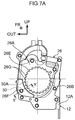
- FIG. 7A is a front view of a cover plate according to a variant example of the exemplary embodiment of the present invention.
- FIG. 7B is a bottom view of the cover plate according to the variant example of the exemplary embodiment of the present invention.
- FIG. 7C is a sectional diagram of the cover plate according to the variant example of the exemplary embodiment of the present invention (a sectional diagram cut along line Y-Y in FIG. 7A ).
- FIG. 1 to FIG. 5 A webbing take-up device 10 according to an exemplary embodiment of the present invention is described using FIG. 1 to FIG. 5 .
- the arrow FR that is shown where appropriate in the drawings indicates the vehicle front (progress direction) and the arrow UP that is shown where appropriate in the drawings indicates the vehicle upper side.
- the arrow OUT indicates an outer side in the vehicle width direction.
- the webbing take-up device 10 depicted in FIG. 1 is installed in the vehicle that is not shown in the drawings, and is provided with a frame 12 that structures a main body of the webbing take-up device 10 .
- the frame 12 depicted in FIG. 2 is fixed to a vehicle lower side portion of a center pillar of the vehicle, which is not shown in the drawings.
- the frame 12 is formed in a square tube shape as viewed in the vehicle vertical direction. More specifically, the frame 12 includes a leg plate 12 A and a leg plate 12 B that oppose one another substantially in the vehicle front-and-rear direction, and a rear plate 12 C and a front plate 12 D that oppose one another substantially in the vehicle width direction.
- the rear plate 12 C and front plate 12 D link together end portions at both sides in the vehicle width direction of the leg plate 12 A with end portions at both sides in the vehicle width direction of the leg plate 12 B.
- the leg plate 12 A extends substantially in the vehicle width direction and the vehicle vertical direction, with a thickness direction in the vehicle front-and-rear direction.
- a cover plate 26 which is described below, is attached to the leg plate 12 A from the vehicle rear side thereof.
- a first hole portion 13 A and plural second hole portions 13 B are formed in the leg plate 12 A.
- the first hole portion 13 A penetrates through the leg plate 12 A in the vehicle front-and-rear direction in a region of the leg plate 12 A that is substantially central in the vehicle width direction and the vehicle vertical direction. Viewed in the vehicle front-and-rear direction, the first hole portion 13 A is formed in a circular shape.
- the size of the first hole portion 13 A is a size into which a spool 14 , which is described below, can be inserted in the vehicle front-and-rear direction, and is a size that allows rotation of the spool 14 about a central axis thereof.
- the frame 12 supports the spool 14 to be rotatable.
- the plural second hole portions 13 B are formed in portions of the leg plate 12 A that are peripheral to the first hole portion 13 A.
- the second hole portions 13 B penetrate through the leg plate 12 A in the vehicle front-and-rear direction. Rivets 21 A and rivets 21 B are inserted into the plural second hole portions 13 B.
- the leg plate 12 B is disposed at the vehicle front side relative to the leg plate 12 A, and extends substantially in the vehicle width direction and the vehicle vertical direction.
- a third hole portion 15 A is formed in the leg plate 12 B.
- the third hole portion 15 A penetrates through the leg plate 12 B in the vehicle front-and-rear direction.
- a size of the third hole portion 15 A is a size into which a vehicle front side end portion of the spool 14 can be inserted, and is a size that allows rotation of the spool 14 about the central axis thereof.
- the spool 14 illustrated in FIG. 3 is provided at the frame 12 (see FIG. 2 )
- the spool 14 is rotatable about a central axis K along the axial direction substantially in the vehicle front-and-rear direction.
- a length direction base end portion of a webbing 16 in a long, narrow belt shape is anchored at the spool 14 .
- the webbing 16 is taken up onto the spool 14 from the length direction base end side thereof by the spool 14 being rotated in a take-up direction (the direction of arrow A).
- a length direction distal end side of the webbing 16 extends from the spool 14 toward the vehicle upper side.
- the length direction distal end side of the webbing 16 passes through a slit hole in a through anchor, which is not shown in the drawings, and is turned back toward the vehicle lower side.
- the through anchor is supported at the center pillar that is not shown in the drawings.
- a length direction distal end portion of the webbing 16 is anchored at an anchor plate, which is not shown in the drawings.
- the anchor plate is formed by a metal plate of steel or the like.
- the anchor plate is fixed to a floor portion of the vehicle, a framework member of a seat corresponding with the webbing take-up device 10 , or the like, which are not shown in the drawings.
- a seatbelt device for a vehicle at which the webbing take-up device 10 is employed includes a buckle apparatus, which is not shown in the drawings.
- the buckle apparatus is provided at the vehicle width direction inner side of the seat at which the webbing take-up device 10 is employed.
- a tongue provided at the webbing 16 is engaged with the buckle apparatus.
- the webbing 16 is applied to the body of the vehicle occupant.
- a spring housing 36 is provided at the vehicle front side relative to the frame 12 illustrated in FIG. 1 .
- a spool urging means such as a spiral spring or the like, which is not shown in the drawings, is provided inside the spring housing 36 .
- the spool 14 is urged in the take-up direction of the webbing 16 (the direction of arrow A shown in FIG. 3 ) by an urging force of the spool urging means.
- a lock mechanism 37 is provided at the vehicle rear side relative to the frame 12 .
- the lock mechanism 37 includes a lock base 38 that serves as a rotary member, a lock pawl 42 that is provided at the lock base 38 , and a sensor mechanism, which is not shown in the drawings, that is activated when there is an emergency during a vehicle collision or the like.
- the lock base 38 is provided at one axial direction end side (the vehicle rear side) of the spool 14 .
- a vehicle front side of the lock base 38 is linked with a pinion 24 .
- the lock base 38 includes a main body portion 38 A, at which the lock pawl 42 is mounted, and a flange 38 B provided at the outer periphery of the main body portion 38 A.
- a torsion shaft 18 that serves as an axle portion is accommodated in an axial center portion of the spool 14 .
- the torsion shaft 18 is formed in a circular rod shape whose axial direction is substantially in the vehicle front-and-rear direction.
- One end portion (a portion at the vehicle front side) of the axial direction of the torsion shaft 18 is retained by the spool 14 in a state in which relative rotation of the torsion shaft 18 with respect to the spool 14 is prevented.
- the other end portion (a portion at the vehicle rear side) of the axial direction of the torsion shaft 18 is linked to the lock base 38 via the pinion 24 that is described below.
- the lock base 38 is linked to the spool 14 by the pinion 24 and the torsion shaft 18 in a state in which relative rotation of the lock base 38 with respect to the spool 14 is prevented.
- the pinion 24 is disposed at the vehicle rear side relative to the frame 12 (see FIG. 1 ) but at the vehicle front side relative to the cover plate 26 (see FIG. 1 ), which is described below.
- An axial direction of the pinion 24 is substantially in the vehicle front-and-rear direction, and the pinion 24 is linked with the torsion shaft 18 and the lock base 38 (see FIG. 5 ).
- a tooth portion 25 is formed at the outer periphery of the pinion 24 .
- the tooth portion 25 is constituted by a plural number of engaging teeth 25 A.
- a flange 25 B is also provided at the outer periphery of the pinion 24 , adjacent to the vehicle front side of the tooth portion 25 .
- the pinion 24 is joined to the lock base 38 .
- the rotary member is structured by the pinion 24 and the lock base 38 .
- the plural engaging teeth 25 A are formed in radiating shapes at constant angular intervals around the central axis of the pinion 24 . Distal ends of the engaging teeth 25 A are disposed such that, when the pinion 24 rotates, the distal ends trace a circular path passing beside an opening portion 31 (see FIG. 2 ) at an axial direction distal end portion (a vehicle lower side end portion) of a pipe 28 (see FIG. 2 ), which is described below.
- a rack 32 (see FIG. 2 ), which is described below, contacts the engaging teeth 25 A and the pinion 24 rotates (about the axis thereof), the pinion 24 applies rotary force to the spool 14 . In this situation, as illustrated in FIG. 5 , the rack 32 is sandwiched and rotates between the flange 25 B of the pinion 24 and the flange 38 B of the lock base 38 .
- the cover plate 26 which serves as an example of an outer periphery body, is attached to a rear face 17 of the frame 12 .
- the cover plate 26 is superposed with and fixed to the leg plate 12 A of the frame 12 from the vehicle rear side thereof, using the rivets 21 A and the rivets 21 B.
- the cover plate 26 includes a rear wall portion 26 A, a peripheral wall portion 26 B, a pipe attachment portion 26 C and a flange 26 D.
- the cover plate 26 functions to accommodate the rack 32 , which is described below, to be movable when the rack 32 emerges from the pipe 28 .
- the rear wall portion 26 A is a wall portion substantially along the vehicle width direction and the vehicle vertical direction.
- the rear wall portion 26 A is disposed to oppose the leg plate 12 A of the frame 12 in the vehicle front-and-rear direction.
- the ratchet hole 26 E is formed penetrating through the rear wall portion 26 A in the vehicle front-and-rear direction at a central region of the rear wall portion 26 A in the vehicle width direction and the vehicle vertical direction.
- the ratchet hole 26 E includes the plural ratchet teeth 26 G which, viewed in the vehicle front-and-rear direction, are arrayed in the circumferential direction of the ratchet hole 26 E.
- the peripheral wall portion 26 B is an interior wall face that intersects the rotation radial direction of the lock base 38 .
- the peripheral wall portion 26 B extends to the vehicle front side from peripheral edges of the rear wall portion 26 A. Viewed in the vehicle front-and-rear direction, the peripheral wall portion 26 B is arranged in an annular shape so as to encircle the ratchet hole 26 E.
- the pipe attachment portion 26 C is formed integrally with the peripheral wall portion 26 B in a region at a vehicle upper side end portion of a vehicle width direction inner side end portion of the peripheral wall portion 26 B. That is, the pipe attachment portion 26 C is formed integrally with the peripheral wall portion 26 B at the vehicle width direction inner side end portion and vehicle upper side end portion relative to a central axis line K of the spool 14 (see FIG. 3 ).
- the pipe attachment portion 26 C widens so as to engage with a circumferential direction portion of a flange portion 29 of the pipe 28 , which is described below.
- the flange 26 D is a portion that protrudes substantially in the vehicle width direction and the vehicle vertical direction from an outer periphery of the peripheral wall portion 26 B.
- Plural hole portions 26 F are formed in the flange 26 D.
- the hole portions 26 F penetrate through the flange 26 D in the vehicle front-and-rear direction, matching up with the plural second hole portions 13 B.
- the hole portions 26 F are formed with larger diameters than outer diameters of the shaft portions of the rivets 21 A and outer diameters of the shaft portions of the rivets 21 B.
- the flange 26 D is fastened to the frame 12 by the rivets 21 A and the rivets 21 B.
- a guide 30 that serves as a bracing portion is provided at a back face (the face at the vehicle front side) of the rear wall portion 26 A.
- the guide 30 is provided at the vehicle width direction outer side and vehicle lower side of the rear wall portion 26 A.
- the guide 30 is provided at the opposite side of a rotation center O of the pinion 24 from a location at which the tooth portion 25 and rack 32 contact.
- the guide 30 is fixed to the rear wall portion 26 A by a pair of rivets 30 D.
- the guide 30 includes a curved wall face 30 A, a vertical wall face 30 B and a horizontal wall face 30 C.
- the curved wall face 30 A is a contact surface in a curved arc shape that is formed so as to oppose an outer periphery face of the lock base 38 .
- the vertical wall face 30 B is formed substantially in the vehicle vertical direction
- the horizontal wall face 30 C is formed substantially in the vehicle width direction.
- the vertical wall face 30 B and horizontal wall face 30 C abut against a back face of the peripheral wall portion 26 B (the face thereof at the side at which the pinion 24 is disposed).
- the guide 30 is provided such that, if a distance between the curved wall face 30 A and an outer periphery face (an outer periphery face 38 C) of the flange 38 B of the lock base 38 is represented by L 1 , and a distance between tip portions of the ratchet teeth 26 G and the main body portion 38 A of the lock base 38 is represented by L 2 , then L 1 ⁇ L 2 .
- L 1 a distance between the curved wall face 30 A and an outer periphery face (an outer periphery face 38 C) of the flange 38 B of the lock base 38
- L 1 a distance between tip portions of the ratchet teeth 26 G and the main body portion 38 A of the lock base 38
- L 2 a distance between tip portions of the ratchet teeth 26 G and the main body portion 38 A of the lock base 38
- the pipe 28 is attached to the leg plate 12 A of the frame 12 .
- the pipe 28 is formed in a circular tube shape.
- An inner diameter of the pipe 28 is larger than an outer diameter of the rack 32 such that the pipe 28 accommodates the rack 32 , which is described below, and the rack 32 is movable in an axial direction of the rack 32 .
- the pipe 28 is inflected at, for example, three locations. More specifically, the pipe 28 is provided with a base end portion 28 A, a first inflection portion 28 B, a second inflection portion 28 C, a linear portion 28 D, a third inflection portion 28 E, and a mounting portion 28 F.
- the base end portion 28 A is a portion of the pipe 28 that extends linearly with the axial direction thereof substantially in the vehicle vertical direction.
- the flange portion 29 is provided at an axial direction portion of the base end portion 28 A.
- the flange portion 29 protrudes in the diametric directions of the base end portion 28 A.
- the opening portion 31 which opens in the axial direction of the base end portion 28 A, is formed at one end of the base end portion 28 A (the lower end in FIG. 2 ).
- a micro gas generator 34 is provided at the mounting portion 28 F.
- the rack 32 illustrated in FIG. 2 which serves as a moving member, is a rod-shaped member fabricated from resin.
- the rack 32 is fabricated from a synthetic resin.
- the rack 32 is formed in a cylindrical shape (rod shape) of a material that is softer than the lock base 38 and the pinion 24 (see FIG. 3 ).
- the rack 32 is accommodated inside the pipe 28 so as to be movable in the axial direction of the rack 32 .
- a sealing ball 44 is also disposed inside the pipe 28 , between the rack 32 and the micro gas generator 34 .
- the shape of the rack 32 in a cross section orthogonal to the movement direction (axial direction) thereof is a circle.
- the rack 32 illustrated in FIG. 2 moves inside the pipe 28 , emerges outside the pipe 28 , and moves inside the cover plate 26 .
- the rack 32 contacts the tooth portion 25 (see FIG. 3 and FIG. 4 ) from the distal end side of the rack 32 (the side thereof at which the pinion 24 is disposed), and causes the pinion 24 to rotate about the axis of the pinion 24 .
- the rack 32 applies rotary force in the circumferential direction of the pinion 24 and spool 14 .
- the micro gas generator 34 illustrated in FIG. 2 is electronically connected, via an electronic control unit (ECU) that serves as a controller, with a collision prediction sensor, which is not shown in the drawings, provided at the vehicle.
- ECU electronice control unit
- a collision prediction sensor which is not shown in the drawings, provided at the vehicle.
- the micro gas generator 34 is activated by the ECU, and gas generated by the micro gas generator 34 is supplied into the pipe 28 .
- the micro gas generator 34 is a gas generator, which is an aspect of a fluid supply means.
- the rack 32 rotates the pinion 24 and lock base 38 that serve as the rotary member.
- the operation of taking up the webbing 16 in the direction of arrow A is commenced.
- the rack 32 engages with the engaging teeth 25 A of the pinion 24
- the rack 32 pushes the pinion 24 and lock base 38 to the rotation center O side (the side indicated by arrow C in FIG. 4 ).
- the lock base 38 is supported by the guide 30 to be rotatable.
- contact between the ratchet teeth 26 G and the main body portion 38 A of the lock base 38 is restricted.
- the present exemplary embodiment and the comparative example contrast as follows. As illustrated in FIG. 6 , the comparative example is different in that the guide 30 included in the present exemplary embodiment is not provided.
- the guide 30 because the guide 30 is provided, contacting of the ratchet teeth 26 G against the lock base 38 is inhibited. More specifically, as mentioned above, the guide 30 is provided such that the relationship L 1 ⁇ L 2 applies (see FIG. 5 ). Therefore, when the rack 32 contacts the engaging teeth 25 A of the pinion 24 and pushes the pinion 24 and lock base 38 to the rotation center O side, decentering the pinion 24 and lock base 38 , the curved wall face 30 A of the guide 30 and the outer periphery face 38 C of the flange 38 B contact together before the ratchet teeth 26 G and the main body portion 38 A contact together. In the present exemplary embodiment described above, because the guide 30 supports the lock base 38 that serves as the rotary member to be rotatable, contact of the ratchet teeth 26 G against the outer periphery face of the main body portion 38 A may be inhibited.
- the flange 38 B at which the outer periphery face 38 C is provided functions to support the decentered pinion 24 and lock base 38 to be rotatable.
- the flange 38 B also functions to limit movement of the pinion 24 and lock base 38 in a thrust direction (the axial direction).
- the lock base 38 does not contact the ratchet teeth 26 G but contacts and is supported by the curved wall face 30 A of the guide 30 . Therefore, a surface pressure that the lock base 38 is subjected to as a result of contacting another member may be lowered.
- the surface pressure that the lock base 38 is subjected to is lowered, the hardnesses of the materials of the ratchet teeth 26 G, the lock base 38 and the like may be lowered, and fabrication costs may be suppressed.
- the rack 32 ejected from the base end portion 28 A of the pipe 28 contacts the engaging teeth 25 A at the vehicle upper side of the vehicle width direction inner side of the pinion 24 . Consequently, in the present exemplary embodiment, the pinion 24 and the lock base 38 connected with the pinion 24 are pushed to the rotation center O side (in the direction of arrow C) by the rack 32 fabricated from resin and are decentered.
- the guide 30 according to the present exemplary embodiment is not provided over the whole outer periphery of the ratchet hole 26 E (see FIG. 2 ) but is provided at the vehicle width direction outer side and vehicle lower side of the cover plate 26 .
- the guide 30 sandwiches the rotation center O at the opposite side thereof from the location at which the rack 32 and the engaging teeth 25 A contact together.
- the guide 30 is provided at the side toward which the pinion 24 and lock base 38 are decentered.
- the direction in which the pinion 24 and lock base 38 are decentered is determined in advance, it is sufficient to provide the guide 30 only at the side toward which the pinion 24 and lock base 38 are decentered.
- fabrication costs may be suppressed.
- the vertical wall face 30 B and horizontal wall face 30 C of the guide 30 abut against the back face of the peripheral wall portion 26 B (the face at the side thereof at which the pinion 24 is disposed) of the cover plate 26 (see FIG. 5 ).
- the guide 30 is fixed to the rear wall portion 26 A by the pair of rivets 30 D.
- a pushing force that the curved wall face 30 A receives from the pinion 24 and lock base 38 is directly transmitted to the peripheral wall portion 26 B of the cover plate 26 by the abutting of the guide 30 against the peripheral wall portion 26 B.
- the guide 30 according to the present embodiment bears the pushing force with the peripheral wall portion 26 B, a fixing strength of the rivets 30 D may be reduced. Hence, if the fixing of the guide 30 can be simplified, fabrication costs of the webbing take-up device 10 may be suppressed.
- the present invention is not limited by the exemplary embodiment described above but encompasses the variant example described below.
- the guide 30 according to the present exemplary embodiment is fixed to the rear wall portion 26 A by the pair of rivets 30 D, but the guide 30 according to the variant example is formed integrally with the cover plate 26 .
- a front view illustrating the exterior of the cover plate 26 according to this variant example is depicted in FIG. 7A .
- FIG. 7B is a bottom view of the cover plate 26
- FIG. 7C is a sectional diagram of a section cut along line Y-Y of FIG. 7A .
- the rear wall portion 26 A of the cover plate 26 is plastically deformed toward the vehicle front side at the guide 30 .
- the cover plate 26 is formed by press-machining of a metal plate member; a region for forming the guide 30 is provided at a pressing die in advance.
- the lock base 38 may be supported to be rotatable by the curved wall face 30 A.
- the webbing take-up device 10 because there is no need, as when the guide 30 is formed as a separate component, to attach the guide 30 to the cover plate 26 subsequently, a number of fabrication steps and a number of components may be reduced. Thus, fabrication costs of the webbing take-up device 10 may be reduced.
- the lock pawl 42 is provided at the lock base 38 that serves as the rotary member and the ratchet teeth 26 G are provided at the cover plate 26 , but this is not limiting. It is sufficient that the ratchet teeth are provided at one of the lock base 38 and the cover plate 26 and the lock pawl 42 is provided at the other of the lock base 38 and the cover plate 26 .
- the ratchet teeth may be provided at the lock base 38 and the lock pawl provided at the cover plate 26 .
- ratchet teeth or lock pawl may be provided at the leg plate 12 A of the frame 12 instead of at the cover plate 26 , and the lock base 38 may be disposed at a position that enables locking with the frame 12 .
- the rack 32 fabricated from resin rotates the spool 14 by engaging with the engaging teeth 25 A of the pinion 24 , but a method of rotation is not limited thus.
- a method of rotation is not limited thus.
- a method of rotation based on meshing this gear portion with a gear portion at the pinion side may be employed, or a method of rotation by abutting metal balls arrayed in a row with the tooth portion of the pinion may be employed.
- the pinion 24 and lock base 38 that serve as the rotary member are formed as separate bodies, but this is not limiting; the pinion 24 and lock base 38 may be formed as a single body.
- the pinion 24 and lock base 38 may be formed as a single body by aluminium die-casting.
- the frame 12 is not limited to being in a square tube shape as seen in the vehicle vertical direction; the frame 12 may have a polygonal tube shape other than a square tube shape.
- the leg plate 12 A is not limited to a flat shape along the vehicle width direction and the vehicle vertical direction; the leg plate 12 A may include a curved surface.
- the shape of the pipe 28 viewed in the axial direction thereof is not limited to a circular shape but may be a polygonal shape.
Applications Claiming Priority (4)
| Application Number | Priority Date | Filing Date | Title |
|---|---|---|---|
| JP2016-245909 | 2016-12-19 | ||
| JP2016245909A JP6539638B2 (ja) | 2016-12-19 | 2016-12-19 | ウェビング巻取装置 |
| JPJP2016-245909 | 2016-12-19 | ||
| PCT/JP2017/041542 WO2018116719A1 (ja) | 2016-12-19 | 2017-11-17 | ウェビング巻取装置 |
Publications (2)
| Publication Number | Publication Date |
|---|---|
| US20200086826A1 US20200086826A1 (en) | 2020-03-19 |
| US11001226B2 true US11001226B2 (en) | 2021-05-11 |
Family
ID=62627308
Family Applications (1)
| Application Number | Title | Priority Date | Filing Date |
|---|---|---|---|
| US16/469,828 Active 2038-01-11 US11001226B2 (en) | 2016-12-19 | 2017-11-17 | Webbing take-up device |
Country Status (5)
| Country | Link |
|---|---|
| US (1) | US11001226B2 (ja) |
| JP (1) | JP6539638B2 (ja) |
| CN (1) | CN110114247B (ja) |
| DE (1) | DE112017006360T5 (ja) |
| WO (1) | WO2018116719A1 (ja) |
Families Citing this family (2)
| Publication number | Priority date | Publication date | Assignee | Title |
|---|---|---|---|---|
| JP2021091337A (ja) * | 2019-12-11 | 2021-06-17 | Joyson Safety Systems Japan株式会社 | シートベルトリトラクタ及びシートベルト装置 |
| JP2022078727A (ja) | 2020-11-13 | 2022-05-25 | Joyson Safety Systems Japan株式会社 | シートベルトリトラクタ及びシートベルト装置 |
Citations (8)
| Publication number | Priority date | Publication date | Assignee | Title |
|---|---|---|---|---|
| JPH10119719A (ja) | 1996-10-17 | 1998-05-12 | Nippon Seiko Kk | シートベルト用リトラクター |
| JPH10310026A (ja) | 1997-05-09 | 1998-11-24 | Nippon Seiko Kk | シートベルト用リトラクター |
| JP2002200965A (ja) | 2000-11-06 | 2002-07-16 | Nsk Autoliv Co Ltd | シートベルト装置 |
| JP2007069686A (ja) | 2005-09-06 | 2007-03-22 | Takata Corp | シートベルトリトラクタ及びシートベルト装置 |
| US20110140501A1 (en) * | 2009-12-15 | 2011-06-16 | Takata Corporation | Seat belt retractor and seat belt apparatus including the same |
| JP2015054651A (ja) | 2013-09-13 | 2015-03-23 | タカタ株式会社 | シートベルトリトラクタ及びシートベルト装置 |
| JP2015054650A (ja) | 2013-09-13 | 2015-03-23 | タカタ株式会社 | シートベルトリトラクタ及びシートベルト装置 |
| US20190308585A1 (en) * | 2016-06-09 | 2019-10-10 | Kabushiki Kaisha Tokai-Rika-Denki-Seisakusho | Webbing take-up device |
Family Cites Families (12)
| Publication number | Priority date | Publication date | Assignee | Title |
|---|---|---|---|---|
| JP3437488B2 (ja) * | 1999-02-16 | 2003-08-18 | 株式会社東海理化電機製作所 | ウエビング巻取装置 |
| JP3886665B2 (ja) * | 1999-04-28 | 2007-02-28 | 芦森工業株式会社 | シートベルトプリテンショナー |
| KR100348163B1 (ko) * | 2000-06-22 | 2002-08-09 | 델파이 오토모티브 시스템스 성우 주식회사 | 좌석벨트 리트랙터의 동력전달장치 일체형 프리텐셔너 |
| JP5078110B2 (ja) * | 2006-06-15 | 2012-11-21 | タカタ株式会社 | シートベルトリトラクタおよびこれを備えているシートベルト装置 |
| JP4976241B2 (ja) * | 2007-09-04 | 2012-07-18 | タカタ株式会社 | シートベルトリトラクタおよびこれを用いたシートベルト装置 |
| DE102010051422A1 (de) * | 2010-11-17 | 2012-05-24 | Trw Automotive Gmbh | Gurtstraffer für Gurtaufroller mit Kraftbegrenzungsvorrichtung und Verfahren zum Straffen eines Sicherheitsgurts und anschließender Kraftbegrenzung |
| DE102010054845A1 (de) * | 2010-12-16 | 2013-03-14 | Trw Automotive Gmbh | Gurtaufroller eines Sicherheitgurtsystems |
| JP6091967B2 (ja) * | 2013-04-03 | 2017-03-08 | 株式会社東海理化電機製作所 | プリテンショナ機構 |
| JP2015217729A (ja) * | 2014-05-15 | 2015-12-07 | タカタ株式会社 | プリテンショナ、リトラクタ及びシートベルト装置 |
| DE102014114653B3 (de) * | 2014-08-05 | 2015-07-02 | Autoliv Development Ab | Gurtstraffer mit einer Sicke an dem Strafferrohr |
| JP6421003B2 (ja) * | 2014-09-22 | 2018-11-07 | Joyson Safety Systems Japan株式会社 | プリテンショナ、リトラクタ及びシートベルト装置 |
| JP2017069686A (ja) | 2015-09-29 | 2017-04-06 | パナソニックIpマネジメント株式会社 | コントローラ |
-
2016
- 2016-12-19 JP JP2016245909A patent/JP6539638B2/ja active Active
-
2017
- 2017-11-17 WO PCT/JP2017/041542 patent/WO2018116719A1/ja active Application Filing
- 2017-11-17 DE DE112017006360.4T patent/DE112017006360T5/de active Pending
- 2017-11-17 CN CN201780078440.0A patent/CN110114247B/zh active Active
- 2017-11-17 US US16/469,828 patent/US11001226B2/en active Active
Patent Citations (11)
| Publication number | Priority date | Publication date | Assignee | Title |
|---|---|---|---|---|
| JPH10119719A (ja) | 1996-10-17 | 1998-05-12 | Nippon Seiko Kk | シートベルト用リトラクター |
| US5887814A (en) | 1996-10-17 | 1999-03-30 | Nsk Ltd. | Seat belt retractor and controlling method of the same |
| JPH10310026A (ja) | 1997-05-09 | 1998-11-24 | Nippon Seiko Kk | シートベルト用リトラクター |
| US5954287A (en) | 1997-05-09 | 1999-09-21 | Nsk Ltd. | Retractor for a seat belt |
| JP2002200965A (ja) | 2000-11-06 | 2002-07-16 | Nsk Autoliv Co Ltd | シートベルト装置 |
| JP2007069686A (ja) | 2005-09-06 | 2007-03-22 | Takata Corp | シートベルトリトラクタ及びシートベルト装置 |
| US20110140501A1 (en) * | 2009-12-15 | 2011-06-16 | Takata Corporation | Seat belt retractor and seat belt apparatus including the same |
| JP2015054651A (ja) | 2013-09-13 | 2015-03-23 | タカタ株式会社 | シートベルトリトラクタ及びシートベルト装置 |
| JP2015054650A (ja) | 2013-09-13 | 2015-03-23 | タカタ株式会社 | シートベルトリトラクタ及びシートベルト装置 |
| US20160221534A1 (en) | 2013-09-13 | 2016-08-04 | Takata Corporation | Seat belt retractor and seat belt apparatus |
| US20190308585A1 (en) * | 2016-06-09 | 2019-10-10 | Kabushiki Kaisha Tokai-Rika-Denki-Seisakusho | Webbing take-up device |
Non-Patent Citations (1)
| Title |
|---|
| International Search Report and Written Opinion issued in corresponding International Application No. PCT/JP2017/041542 dated Feb. 13, 2018. |
Also Published As
| Publication number | Publication date |
|---|---|
| WO2018116719A1 (ja) | 2018-06-28 |
| DE112017006360T5 (de) | 2019-09-05 |
| JP6539638B2 (ja) | 2019-07-03 |
| JP2018099943A (ja) | 2018-06-28 |
| CN110114247A (zh) | 2019-08-09 |
| CN110114247B (zh) | 2021-06-29 |
| US20200086826A1 (en) | 2020-03-19 |
Similar Documents
| Publication | Publication Date | Title |
|---|---|---|
| EP3293060B1 (en) | Pretensioner, retractor and seat belt device | |
| WO2017213238A1 (ja) | ウェビング巻取装置 | |
| JP6827043B2 (ja) | ウェビング巻取装置 | |
| US20080116309A1 (en) | Webbing Retractor | |
| JP5734889B2 (ja) | プリテンショナ機構 | |
| US11001226B2 (en) | Webbing take-up device | |
| US10723311B2 (en) | Webbing take-up device | |
| WO2017069047A1 (ja) | シートベルトリトラクタ及びシートベルト装置 | |
| JP2012035644A (ja) | ウェビング巻取装置 | |
| US20190299923A1 (en) | Webbing take-up device | |
| WO2017213188A1 (ja) | ウェビング巻取装置 | |
| US10906503B2 (en) | Webbing take-up device | |
| JP2014088108A (ja) | プリテンショナ機構 | |
| JP5975845B2 (ja) | プリテンショナ機構 | |
| US11066042B2 (en) | Webbing take-up device | |
| JP6843182B2 (ja) | ウェビング巻取装置 | |
| JP2010018179A (ja) | ウェビング巻取装置 | |
| WO2022064793A1 (ja) | ウェビング巻取装置 | |
| WO2021162031A1 (ja) | ウェビング巻取装置 | |
| WO2022064792A1 (ja) | ウェビング巻取装置 | |
| JP6752630B2 (ja) | ウェビング巻取装置 | |
| JP2017100684A (ja) | ウェビング巻取装置 | |
| JP2022133159A (ja) | ウェビング巻取装置 | |
| JP2022134558A (ja) | プリテンショナ、リトラクタ及びシートベルト装置 | |
| JP2017218091A (ja) | ウェビング巻取装置 |
Legal Events
| Date | Code | Title | Description |
|---|---|---|---|
| AS | Assignment |
Owner name: KABUSHIKI KAISHA TOKAI-RIKA-DENKI-SEISAKUSHO, JAPAN Free format text: ASSIGNMENT OF ASSIGNORS INTEREST;ASSIGNORS:YANAGAWA, WATARU;OKUBO, SHINICHI;HASHIMOTO, SHIGEKI;SIGNING DATES FROM 20190531 TO 20190610;REEL/FRAME:049470/0331 |
|
| FEPP | Fee payment procedure |
Free format text: ENTITY STATUS SET TO UNDISCOUNTED (ORIGINAL EVENT CODE: BIG.); ENTITY STATUS OF PATENT OWNER: LARGE ENTITY |
|
| STPP | Information on status: patent application and granting procedure in general |
Free format text: RESPONSE TO NON-FINAL OFFICE ACTION ENTERED AND FORWARDED TO EXAMINER |
|
| STPP | Information on status: patent application and granting procedure in general |
Free format text: NOTICE OF ALLOWANCE MAILED -- APPLICATION RECEIVED IN OFFICE OF PUBLICATIONS |
|
| STPP | Information on status: patent application and granting procedure in general |
Free format text: PUBLICATIONS -- ISSUE FEE PAYMENT RECEIVED |
|
| STPP | Information on status: patent application and granting procedure in general |
Free format text: PUBLICATIONS -- ISSUE FEE PAYMENT VERIFIED |
|
| STCF | Information on status: patent grant |
Free format text: PATENTED CASE |