JP6863243B2 - 電子機器の取付機構 - Google Patents
電子機器の取付機構 Download PDFInfo
- Publication number
- JP6863243B2 JP6863243B2 JP2017220304A JP2017220304A JP6863243B2 JP 6863243 B2 JP6863243 B2 JP 6863243B2 JP 2017220304 A JP2017220304 A JP 2017220304A JP 2017220304 A JP2017220304 A JP 2017220304A JP 6863243 B2 JP6863243 B2 JP 6863243B2
- Authority
- JP
- Japan
- Prior art keywords
- engine
- electronic device
- wall portion
- bottom wall
- sensor
- Prior art date
- Legal status (The legal status is an assumption and is not a legal conclusion. Google has not performed a legal analysis and makes no representation as to the accuracy of the status listed.)
- Active
Links
Images
Classifications
-
- F—MECHANICAL ENGINEERING; LIGHTING; HEATING; WEAPONS; BLASTING
- F16—ENGINEERING ELEMENTS AND UNITS; GENERAL MEASURES FOR PRODUCING AND MAINTAINING EFFECTIVE FUNCTIONING OF MACHINES OR INSTALLATIONS; THERMAL INSULATION IN GENERAL
- F16M—FRAMES, CASINGS OR BEDS OF ENGINES, MACHINES OR APPARATUS, NOT SPECIFIC TO ENGINES, MACHINES OR APPARATUS PROVIDED FOR ELSEWHERE; STANDS; SUPPORTS
- F16M11/00—Stands or trestles as supports for apparatus or articles placed thereon ; Stands for scientific apparatus such as gravitational force meters
- F16M11/02—Heads
- F16M11/16—Details concerning attachment of head-supporting legs, with or without actuation of locking members thereof
-
- F—MECHANICAL ENGINEERING; LIGHTING; HEATING; WEAPONS; BLASTING
- F02—COMBUSTION ENGINES; HOT-GAS OR COMBUSTION-PRODUCT ENGINE PLANTS
- F02M—SUPPLYING COMBUSTION ENGINES IN GENERAL WITH COMBUSTIBLE MIXTURES OR CONSTITUENTS THEREOF
- F02M35/00—Combustion-air cleaners, air intakes, intake silencers, or induction systems specially adapted for, or arranged on, internal-combustion engines
- F02M35/10—Air intakes; Induction systems
- F02M35/10242—Devices or means connected to or integrated into air intakes; Air intakes combined with other engine or vehicle parts
- F02M35/10249—Electrical or electronic devices fixed to the intake system; Electric wiring
-
- F—MECHANICAL ENGINEERING; LIGHTING; HEATING; WEAPONS; BLASTING
- F02—COMBUSTION ENGINES; HOT-GAS OR COMBUSTION-PRODUCT ENGINE PLANTS
- F02F—CYLINDERS, PISTONS OR CASINGS, FOR COMBUSTION ENGINES; ARRANGEMENTS OF SEALINGS IN COMBUSTION ENGINES
- F02F7/00—Casings, e.g. crankcases
- F02F7/006—Camshaft or pushrod housings
-
- F—MECHANICAL ENGINEERING; LIGHTING; HEATING; WEAPONS; BLASTING
- F16—ENGINEERING ELEMENTS AND UNITS; GENERAL MEASURES FOR PRODUCING AND MAINTAINING EFFECTIVE FUNCTIONING OF MACHINES OR INSTALLATIONS; THERMAL INSULATION IN GENERAL
- F16M—FRAMES, CASINGS OR BEDS OF ENGINES, MACHINES OR APPARATUS, NOT SPECIFIC TO ENGINES, MACHINES OR APPARATUS PROVIDED FOR ELSEWHERE; STANDS; SUPPORTS
- F16M11/00—Stands or trestles as supports for apparatus or articles placed thereon ; Stands for scientific apparatus such as gravitational force meters
- F16M11/02—Heads
- F16M11/04—Means for attachment of apparatus; Means allowing adjustment of the apparatus relatively to the stand
- F16M11/06—Means for attachment of apparatus; Means allowing adjustment of the apparatus relatively to the stand allowing pivoting
- F16M11/10—Means for attachment of apparatus; Means allowing adjustment of the apparatus relatively to the stand allowing pivoting around a horizontal axis
-
- F—MECHANICAL ENGINEERING; LIGHTING; HEATING; WEAPONS; BLASTING
- F02—COMBUSTION ENGINES; HOT-GAS OR COMBUSTION-PRODUCT ENGINE PLANTS
- F02M—SUPPLYING COMBUSTION ENGINES IN GENERAL WITH COMBUSTIBLE MIXTURES OR CONSTITUENTS THEREOF
- F02M35/00—Combustion-air cleaners, air intakes, intake silencers, or induction systems specially adapted for, or arranged on, internal-combustion engines
- F02M35/10—Air intakes; Induction systems
- F02M35/10373—Sensors for intake systems
-
- F—MECHANICAL ENGINEERING; LIGHTING; HEATING; WEAPONS; BLASTING
- F02—COMBUSTION ENGINES; HOT-GAS OR COMBUSTION-PRODUCT ENGINE PLANTS
- F02M—SUPPLYING COMBUSTION ENGINES IN GENERAL WITH COMBUSTIBLE MIXTURES OR CONSTITUENTS THEREOF
- F02M35/00—Combustion-air cleaners, air intakes, intake silencers, or induction systems specially adapted for, or arranged on, internal-combustion engines
- F02M35/10—Air intakes; Induction systems
- F02M35/104—Intake manifolds
- F02M35/112—Intake manifolds for engines with cylinders all in one line
Landscapes
- Engineering & Computer Science (AREA)
- General Engineering & Computer Science (AREA)
- Mechanical Engineering (AREA)
- Chemical & Material Sciences (AREA)
- Combustion & Propulsion (AREA)
- Cylinder Crankcases Of Internal Combustion Engines (AREA)
- Exhaust Silencers (AREA)
Description
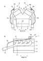
2L、2R バンク
4L、4R ヘッドカバー
5L、5R シリンダヘッド
11L、11R 排気通路
14L、14R センサ(電子機器)
20L、20R 取付機構
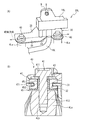
30 ブラケット
31 底壁部
35 側壁部
40 支持部
47 グロメット(弾性体)
Claims (3)
- エンジンのシリンダヘッドを覆うヘッドカバーに電子機器を取り付けるための電子機器の取付機構であって、
前記電子機器を保持したブラケットと、
前記ブラケットを前記ヘッドカバーに対して弾性的に支持した複数の支持部と、を備え、
複数の前記支持部は、前記エンジンの前後方向に沿って並んでおり、
前記電子機器は、前記エンジンの吸気系及び排気系の一方に連通した配管に接続されており、前記吸気系及び排気系の前記一方の圧力を検出するセンサであり、
前記センサは、前記配管と前記吸気系及び排気系の前記一方とが連通した部位よりも、鉛直上方側に位置しており、
前記ブラケットは、複数の前記支持部により前記ヘッドカバーに取り付けられた底壁部と、前記底壁部から鉛直上方側に延びて前記センサが取り付けられた側壁部と、を含む、電子機器の取付機構。 - 前記底壁部は、前記支持部同士の間に前記配管を逃がす切欠部が形成されている、請求項1の電子機器の取付機構。
- 前記支持部は、前記ヘッドカバーと前記底壁部との間に介在した弾性体を有している、請求項1又は2の電子機器の取付機構。
Priority Applications (4)
| Application Number | Priority Date | Filing Date | Title |
|---|---|---|---|
| JP2017220304A JP6863243B2 (ja) | 2017-11-15 | 2017-11-15 | 電子機器の取付機構 |
| US15/929,049 US11168831B2 (en) | 2017-11-15 | 2018-09-25 | Attachment mechanism for electronic equipment for engine |
| EP18197606.9A EP3486472A1 (en) | 2017-11-15 | 2018-09-28 | Attachment mechanism for electronic equipment for engine |
| CN201811284053.5A CN109779778B (zh) | 2017-11-15 | 2018-10-31 | 用于发动机的电子设备的附接机构 |
Applications Claiming Priority (1)
| Application Number | Priority Date | Filing Date | Title |
|---|---|---|---|
| JP2017220304A JP6863243B2 (ja) | 2017-11-15 | 2017-11-15 | 電子機器の取付機構 |
Publications (2)
| Publication Number | Publication Date |
|---|---|
| JP2019090379A JP2019090379A (ja) | 2019-06-13 |
| JP6863243B2 true JP6863243B2 (ja) | 2021-04-21 |
Family
ID=63798815
Family Applications (1)
| Application Number | Title | Priority Date | Filing Date |
|---|---|---|---|
| JP2017220304A Active JP6863243B2 (ja) | 2017-11-15 | 2017-11-15 | 電子機器の取付機構 |
Country Status (4)
| Country | Link |
|---|---|
| US (1) | US11168831B2 (ja) |
| EP (1) | EP3486472A1 (ja) |
| JP (1) | JP6863243B2 (ja) |
| CN (1) | CN109779778B (ja) |
Families Citing this family (1)
| Publication number | Priority date | Publication date | Assignee | Title |
|---|---|---|---|---|
| JP7016596B2 (ja) * | 2020-03-17 | 2022-02-07 | ダイハツ工業株式会社 | 支持ブラケット |
Family Cites Families (22)
| Publication number | Priority date | Publication date | Assignee | Title |
|---|---|---|---|---|
| JPH09207887A (ja) | 1996-01-31 | 1997-08-12 | Suzuki Motor Corp | 船外機のエンジンにおける制御センサ取り付け構造 |
| JPH10223111A (ja) | 1997-02-03 | 1998-08-21 | Honda Motor Co Ltd | 船外機用リレー |
| JP3749026B2 (ja) | 1998-11-27 | 2006-02-22 | 三菱電機株式会社 | ソレノイドバルブの固定装置 |
| JP2001342918A (ja) * | 2000-05-31 | 2001-12-14 | Suzuki Motor Corp | 船外機のインテークマニフォールド |
| US6912996B2 (en) | 2002-04-19 | 2005-07-05 | Yamaha Marine Kabushiki Kaisha | Engine with fuel injection system |
| JP4061968B2 (ja) * | 2002-05-23 | 2008-03-19 | ヤマハマリン株式会社 | 燃料噴射式エンジン及び船外機 |
| JP2006220073A (ja) | 2005-02-10 | 2006-08-24 | Toyota Motor Corp | 内燃機関用センサの取付構造及びカムキャップ構成体 |
| JP2007296997A (ja) * | 2006-05-01 | 2007-11-15 | Honda Motor Co Ltd | 船外機 |
| JP5171427B2 (ja) * | 2008-06-23 | 2013-03-27 | ダイハツ工業株式会社 | 内燃機関におけるカム角度センサの取付け装置 |
| JP5278155B2 (ja) | 2009-05-07 | 2013-09-04 | トヨタ自動車株式会社 | シリンダヘッドカバー |
| JP5496840B2 (ja) | 2010-09-14 | 2014-05-21 | 愛三工業株式会社 | センサ取付構造 |
| JP5314727B2 (ja) | 2011-03-31 | 2013-10-16 | 三菱重工業株式会社 | 定置用エンジンの計装機器設置装置 |
| JP2013124714A (ja) * | 2011-12-14 | 2013-06-24 | Ud Trucks Corp | 制御装置の固定部材 |
| JP6015599B2 (ja) * | 2013-08-30 | 2016-10-26 | アイシン精機株式会社 | センサ支持構造 |
| DE102013219399B4 (de) * | 2013-09-26 | 2023-01-05 | Robert Bosch Gmbh | Anordnung zum verdrehsicheren Einstecken eines Sensors in eine Durchgangsöffnung eines Strömungskanals |
| JP6201858B2 (ja) * | 2014-03-27 | 2017-09-27 | マツダ株式会社 | エンジンのシリンダヘッド構造 |
| CN203978605U (zh) | 2014-08-01 | 2014-12-03 | 东风汽车公司 | 一种发动机与增压器的连接结构 |
| JP6255611B2 (ja) * | 2015-05-29 | 2018-01-10 | 本田技研工業株式会社 | 配管接続構造 |
| JP6366141B2 (ja) * | 2015-05-29 | 2018-08-01 | 本田技研工業株式会社 | 鞍乗り型車両 |
| CN205931277U (zh) * | 2016-08-15 | 2017-02-08 | 中国航空工业集团公司沈阳发动机设计研究所 | 一种带双层减振垫的支架组件 |
| CN206111308U (zh) | 2016-08-31 | 2017-04-19 | 长沙金鹰机电科技有限公司 | 一种新型防爆柴油机 |
| CN206111343U (zh) | 2016-08-31 | 2017-04-19 | 长沙金鹰机电科技有限公司 | 一种柴油机防爆结构 |
-
2017
- 2017-11-15 JP JP2017220304A patent/JP6863243B2/ja active Active
-
2018
- 2018-09-25 US US15/929,049 patent/US11168831B2/en active Active
- 2018-09-28 EP EP18197606.9A patent/EP3486472A1/en active Pending
- 2018-10-31 CN CN201811284053.5A patent/CN109779778B/zh not_active Expired - Fee Related
Also Published As
| Publication number | Publication date |
|---|---|
| CN109779778A (zh) | 2019-05-21 |
| EP3486472A1 (en) | 2019-05-22 |
| US20190145575A1 (en) | 2019-05-16 |
| JP2019090379A (ja) | 2019-06-13 |
| US11168831B2 (en) | 2021-11-09 |
| CN109779778B (zh) | 2021-11-02 |
Similar Documents
| Publication | Publication Date | Title |
|---|---|---|
| JP2013245636A (ja) | 可変バルブタイミング機構付エンジン | |
| JP6863243B2 (ja) | 電子機器の取付機構 | |
| KR101544297B1 (ko) | 정치용 엔진의 계장 기기 설치 장치 | |
| KR100820704B1 (ko) | 자동차 배기계의 전방 마운트 구조 | |
| JP2719037B2 (ja) | 車両用エンジンにおける燃料フイルターの支持装置 | |
| JP2019120166A (ja) | 内燃機関 | |
| JP7392555B2 (ja) | エンジンのオイルクーラの振動低減構造 | |
| KR100820702B1 (ko) | 리어 롤 마운트 어셈블리 | |
| JP5548570B2 (ja) | 振動低減装置 | |
| KR20030031722A (ko) | 엔진 마운팅 장치 | |
| KR20040053828A (ko) | 엔진 마운팅 부재 | |
| KR100570014B1 (ko) | 자동차의 유체형 엔진 마운트 | |
| JP2013124714A (ja) | 制御装置の固定部材 | |
| KR200177087Y1 (ko) | 스쿠터형 이륜 자동차의 엔진 행거구조 | |
| KR100202113B1 (ko) | 엔진마운팅의 유체방진러버 구조 | |
| KR100482809B1 (ko) | 자동차의 엔진 마운트 | |
| KR200147379Y1 (ko) | 엔진 마운팅 인슐레이터 | |
| KR100427073B1 (ko) | 진동감쇠를 위한 롤 리어 브라켓트의 장착 구조 | |
| WO2023238177A1 (ja) | 内燃機関 | |
| JP2008045748A (ja) | 液圧式防振マウント | |
| JP6552153B2 (ja) | 防振装置 | |
| JP2025077085A (ja) | 内燃機関 | |
| JPS6217310A (ja) | マフラ−の取付装置 | |
| JP2004028257A (ja) | 防振装置 | |
| KR19980030133U (ko) | 스톱퍼내장형 엔진마운트 |
Legal Events
| Date | Code | Title | Description |
|---|---|---|---|
| A621 | Written request for application examination |
Free format text: JAPANESE INTERMEDIATE CODE: A621 Effective date: 20200428 |
|
| A977 | Report on retrieval |
Free format text: JAPANESE INTERMEDIATE CODE: A971007 Effective date: 20210210 |
|
| A131 | Notification of reasons for refusal |
Free format text: JAPANESE INTERMEDIATE CODE: A131 Effective date: 20210216 |
|
| A521 | Request for written amendment filed |
Free format text: JAPANESE INTERMEDIATE CODE: A523 Effective date: 20210222 |
|
| TRDD | Decision of grant or rejection written | ||
| A01 | Written decision to grant a patent or to grant a registration (utility model) |
Free format text: JAPANESE INTERMEDIATE CODE: A01 Effective date: 20210302 |
|
| A61 | First payment of annual fees (during grant procedure) |
Free format text: JAPANESE INTERMEDIATE CODE: A61 Effective date: 20210315 |
|
| R151 | Written notification of patent or utility model registration |
Ref document number: 6863243 Country of ref document: JP Free format text: JAPANESE INTERMEDIATE CODE: R151 |