JP6231396B2 - 半導体装置及び半導体装置の製造方法 - Google Patents
半導体装置及び半導体装置の製造方法 Download PDFInfo
- Publication number
- JP6231396B2 JP6231396B2 JP2014023869A JP2014023869A JP6231396B2 JP 6231396 B2 JP6231396 B2 JP 6231396B2 JP 2014023869 A JP2014023869 A JP 2014023869A JP 2014023869 A JP2014023869 A JP 2014023869A JP 6231396 B2 JP6231396 B2 JP 6231396B2
- Authority
- JP
- Japan
- Prior art keywords
- region
- type
- outer peripheral
- exposed
- termination trench
- Prior art date
- Legal status (The legal status is an assumption and is not a legal conclusion. Google has not performed a legal analysis and makes no representation as to the accuracy of the status listed.)
- Expired - Fee Related
Links
Images


Classifications
-
- H—ELECTRICITY
- H10—SEMICONDUCTOR DEVICES; ELECTRIC SOLID-STATE DEVICES NOT OTHERWISE PROVIDED FOR
- H10D—INORGANIC ELECTRIC SEMICONDUCTOR DEVICES
- H10D30/00—Field-effect transistors [FET]
- H10D30/60—Insulated-gate field-effect transistors [IGFET]
- H10D30/64—Double-diffused metal-oxide semiconductor [DMOS] FETs
- H10D30/66—Vertical DMOS [VDMOS] FETs
- H10D30/665—Vertical DMOS [VDMOS] FETs having edge termination structures
-
- H—ELECTRICITY
- H10—SEMICONDUCTOR DEVICES; ELECTRIC SOLID-STATE DEVICES NOT OTHERWISE PROVIDED FOR
- H10D—INORGANIC ELECTRIC SEMICONDUCTOR DEVICES
- H10D12/00—Bipolar devices controlled by the field effect, e.g. insulated-gate bipolar transistors [IGBT]
- H10D12/01—Manufacture or treatment
- H10D12/031—Manufacture or treatment of IGBTs
- H10D12/032—Manufacture or treatment of IGBTs of vertical IGBTs
- H10D12/038—Manufacture or treatment of IGBTs of vertical IGBTs having a recessed gate, e.g. trench-gate IGBTs
-
- H—ELECTRICITY
- H10—SEMICONDUCTOR DEVICES; ELECTRIC SOLID-STATE DEVICES NOT OTHERWISE PROVIDED FOR
- H10D—INORGANIC ELECTRIC SEMICONDUCTOR DEVICES
- H10D30/00—Field-effect transistors [FET]
- H10D30/01—Manufacture or treatment
- H10D30/021—Manufacture or treatment of FETs having insulated gates [IGFET]
- H10D30/028—Manufacture or treatment of FETs having insulated gates [IGFET] of double-diffused metal oxide semiconductor [DMOS] FETs
- H10D30/0291—Manufacture or treatment of FETs having insulated gates [IGFET] of double-diffused metal oxide semiconductor [DMOS] FETs of vertical DMOS [VDMOS] FETs
- H10D30/0297—Manufacture or treatment of FETs having insulated gates [IGFET] of double-diffused metal oxide semiconductor [DMOS] FETs of vertical DMOS [VDMOS] FETs using recessing of the gate electrodes, e.g. to form trench gate electrodes
-
- H—ELECTRICITY
- H10—SEMICONDUCTOR DEVICES; ELECTRIC SOLID-STATE DEVICES NOT OTHERWISE PROVIDED FOR
- H10D—INORGANIC ELECTRIC SEMICONDUCTOR DEVICES
- H10D30/00—Field-effect transistors [FET]
- H10D30/60—Insulated-gate field-effect transistors [IGFET]
- H10D30/64—Double-diffused metal-oxide semiconductor [DMOS] FETs
- H10D30/66—Vertical DMOS [VDMOS] FETs
- H10D30/668—Vertical DMOS [VDMOS] FETs having trench gate electrodes, e.g. UMOS transistors
-
- H—ELECTRICITY
- H10—SEMICONDUCTOR DEVICES; ELECTRIC SOLID-STATE DEVICES NOT OTHERWISE PROVIDED FOR
- H10D—INORGANIC ELECTRIC SEMICONDUCTOR DEVICES
- H10D62/00—Semiconductor bodies, or regions thereof, of devices having potential barriers
- H10D62/10—Shapes, relative sizes or dispositions of the regions of the semiconductor bodies; Shapes of the semiconductor bodies
- H10D62/102—Constructional design considerations for preventing surface leakage or controlling electric field concentration
- H10D62/103—Constructional design considerations for preventing surface leakage or controlling electric field concentration for increasing or controlling the breakdown voltage of reverse-biased devices
- H10D62/104—Constructional design considerations for preventing surface leakage or controlling electric field concentration for increasing or controlling the breakdown voltage of reverse-biased devices having particular shapes of the bodies at or near reverse-biased junctions, e.g. having bevels or moats
-
- H—ELECTRICITY
- H10—SEMICONDUCTOR DEVICES; ELECTRIC SOLID-STATE DEVICES NOT OTHERWISE PROVIDED FOR
- H10D—INORGANIC ELECTRIC SEMICONDUCTOR DEVICES
- H10D62/00—Semiconductor bodies, or regions thereof, of devices having potential barriers
- H10D62/10—Shapes, relative sizes or dispositions of the regions of the semiconductor bodies; Shapes of the semiconductor bodies
- H10D62/102—Constructional design considerations for preventing surface leakage or controlling electric field concentration
- H10D62/103—Constructional design considerations for preventing surface leakage or controlling electric field concentration for increasing or controlling the breakdown voltage of reverse-biased devices
- H10D62/105—Constructional design considerations for preventing surface leakage or controlling electric field concentration for increasing or controlling the breakdown voltage of reverse-biased devices by having particular doping profiles, shapes or arrangements of PN junctions; by having supplementary regions, e.g. junction termination extension [JTE]
- H10D62/106—Constructional design considerations for preventing surface leakage or controlling electric field concentration for increasing or controlling the breakdown voltage of reverse-biased devices by having particular doping profiles, shapes or arrangements of PN junctions; by having supplementary regions, e.g. junction termination extension [JTE] having supplementary regions doped oppositely to or in rectifying contact with regions of the semiconductor bodies, e.g. guard rings with PN or Schottky junctions
- H10D62/107—Buried supplementary regions, e.g. buried guard rings
-
- H—ELECTRICITY
- H10—SEMICONDUCTOR DEVICES; ELECTRIC SOLID-STATE DEVICES NOT OTHERWISE PROVIDED FOR
- H10D—INORGANIC ELECTRIC SEMICONDUCTOR DEVICES
- H10D62/00—Semiconductor bodies, or regions thereof, of devices having potential barriers
- H10D62/10—Shapes, relative sizes or dispositions of the regions of the semiconductor bodies; Shapes of the semiconductor bodies
- H10D62/113—Isolations within a component, i.e. internal isolations
- H10D62/115—Dielectric isolations, e.g. air gaps
-
- H—ELECTRICITY
- H10—SEMICONDUCTOR DEVICES; ELECTRIC SOLID-STATE DEVICES NOT OTHERWISE PROVIDED FOR
- H10D—INORGANIC ELECTRIC SEMICONDUCTOR DEVICES
- H10D62/00—Semiconductor bodies, or regions thereof, of devices having potential barriers
- H10D62/80—Semiconductor bodies, or regions thereof, of devices having potential barriers characterised by the materials
- H10D62/83—Semiconductor bodies, or regions thereof, of devices having potential barriers characterised by the materials being Group IV materials, e.g. B-doped Si or undoped Ge
- H10D62/832—Semiconductor bodies, or regions thereof, of devices having potential barriers characterised by the materials being Group IV materials, e.g. B-doped Si or undoped Ge being Group IV materials comprising two or more elements, e.g. SiGe
- H10D62/8325—Silicon carbide
-
- H—ELECTRICITY
- H10—SEMICONDUCTOR DEVICES; ELECTRIC SOLID-STATE DEVICES NOT OTHERWISE PROVIDED FOR
- H10W—GENERIC PACKAGES, INTERCONNECTIONS, CONNECTORS OR OTHER CONSTRUCTIONAL DETAILS OF DEVICES COVERED BY CLASS H10
- H10W10/00—Isolation regions in semiconductor bodies between components of integrated devices
- H10W10/01—Manufacture or treatment
- H10W10/031—Manufacture or treatment of isolation regions comprising PN junctions
-
- H—ELECTRICITY
- H10—SEMICONDUCTOR DEVICES; ELECTRIC SOLID-STATE DEVICES NOT OTHERWISE PROVIDED FOR
- H10W—GENERIC PACKAGES, INTERCONNECTIONS, CONNECTORS OR OTHER CONSTRUCTIONAL DETAILS OF DEVICES COVERED BY CLASS H10
- H10W10/00—Isolation regions in semiconductor bodies between components of integrated devices
- H10W10/30—Isolation regions comprising PN junctions
-
- H—ELECTRICITY
- H10—SEMICONDUCTOR DEVICES; ELECTRIC SOLID-STATE DEVICES NOT OTHERWISE PROVIDED FOR
- H10D—INORGANIC ELECTRIC SEMICONDUCTOR DEVICES
- H10D12/00—Bipolar devices controlled by the field effect, e.g. insulated-gate bipolar transistors [IGBT]
- H10D12/411—Insulated-gate bipolar transistors [IGBT]
- H10D12/441—Vertical IGBTs
- H10D12/461—Vertical IGBTs having non-planar surfaces, e.g. having trenches, recesses or pillars in the surfaces of the emitter, base or collector regions
- H10D12/481—Vertical IGBTs having non-planar surfaces, e.g. having trenches, recesses or pillars in the surfaces of the emitter, base or collector regions having gate structures on slanted surfaces, on vertical surfaces, or in grooves, e.g. trench gate IGBTs
-
- H—ELECTRICITY
- H10—SEMICONDUCTOR DEVICES; ELECTRIC SOLID-STATE DEVICES NOT OTHERWISE PROVIDED FOR
- H10D—INORGANIC ELECTRIC SEMICONDUCTOR DEVICES
- H10D62/00—Semiconductor bodies, or regions thereof, of devices having potential barriers
- H10D62/10—Shapes, relative sizes or dispositions of the regions of the semiconductor bodies; Shapes of the semiconductor bodies
- H10D62/17—Semiconductor regions connected to electrodes not carrying current to be rectified, amplified or switched, e.g. channel regions
- H10D62/393—Body regions of DMOS transistors or IGBTs
-
- H—ELECTRICITY
- H10—SEMICONDUCTOR DEVICES; ELECTRIC SOLID-STATE DEVICES NOT OTHERWISE PROVIDED FOR
- H10D—INORGANIC ELECTRIC SEMICONDUCTOR DEVICES
- H10D64/00—Electrodes of devices having potential barriers
- H10D64/20—Electrodes characterised by their shapes, relative sizes or dispositions
- H10D64/27—Electrodes not carrying the current to be rectified, amplified, oscillated or switched, e.g. gates
- H10D64/311—Gate electrodes for field-effect devices
- H10D64/411—Gate electrodes for field-effect devices for FETs
- H10D64/511—Gate electrodes for field-effect devices for FETs for IGFETs
- H10D64/514—Gate electrodes for field-effect devices for FETs for IGFETs characterised by the insulating layers
- H10D64/516—Gate electrodes for field-effect devices for FETs for IGFETs characterised by the insulating layers the thicknesses being non-uniform
Landscapes
- Electrodes Of Semiconductors (AREA)
Description
本明細書または図面に説明した技術要素は、単独であるいは各種の組み合わせによって技術的有用性を発揮するものであり、出願時請求項記載の組み合わせに限定されるものではない。また、本明細書または図面に例示した技術は複数目的を同時に達成するものであり、そのうちの一つの目的を達成すること自体で技術的有用性を持つものである。
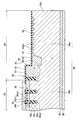
12:半導体基板
20:MOSFET領域
22:ソース領域
26:ボディ領域
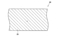
28:ドリフト領域
30:ドレイン領域
32:p型フローティング領域
34:ゲートトレンチ
36:ソース電極
38:ドレイン電極
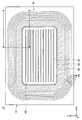
50:外周領域
54:終端トレンチ
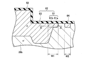
59:境界部p型領域
60:下端p型領域
62:外周p型領域
64:ガードリング領域
70:段差部
Claims (7)
- 半導体基板を有する半導体装置であって、
前記半導体基板内であってその表面に露出しているn型の第1領域と、
前記第1領域の下側に配置されているp型の第2領域と、
前記第2領域の下側に配置されており、前記第2領域によって前記第1領域から分離されているn型の第3領域と、
前記表面に形成されており、前記第1領域及び前記第2領域を貫通して前記第3領域に達する複数のゲートトレンチと、
前記ゲートトレンチ内に配置されている第1絶縁層と、
前記ゲートトレンチ内に配置されており、前記第1絶縁層を介して前記第2領域に対向しているゲート電極と、
前記ゲートトレンチの下端に接するp型の第4領域と、
前記表面に形成されており、前記表面を平面視したときに前記複数のゲートトレンチが形成されている領域の周囲を一巡する終端トレンチと、
前記終端トレンチ内に配置されている第2絶縁層と、
前記終端トレンチの下端に接しており、前記第3領域によって前記第2領域から分離されているp型の下端p型領域と、
前記終端トレンチよりも外周側に形成されており、前記終端トレンチに接しており、前記表面に露出しているp型の外周p型領域と、
前記外周p型領域よりも外周側に形成されており、前記表面に露出しているp型の複数のガードリング領域と、
前記終端トレンチよりも外周側に形成されており、前記第3領域と繋がっており、前記外周p型領域を前記複数のガードリング領域から分離しており、前記複数のガードリング領域を互いから分離しているn型の外周n型領域、
を有し、
前記表面に段差部が形成されていることによって、前記表面が、第1表面と、前記第1表面から突出する第2表面を有しており、
前記終端トレンチが、前記第2表面に形成されており、
前記外周p型領域が、前記第2表面から前記第1表面に跨る範囲に露出しており、
前記複数のガードリング領域が、前記第1表面に露出している、
半導体装置。 - 前記ガードリング領域が、Alを含有する請求項1の半導体装置。
- 半導体基板を有する半導体装置であって、
前記半導体基板内であってその表面に露出しているn型の第1領域と、
前記第1領域の下側に配置されているp型の第2領域と、
前記第2領域の下側に配置されており、前記第2領域によって前記第1領域から分離されているn型の第3領域と、
前記表面に形成されており、前記第1領域及び前記第2領域を貫通して前記第3領域に達する複数のゲートトレンチと、
前記ゲートトレンチ内に配置されている第1絶縁層と、
前記ゲートトレンチ内に配置されており、前記第1絶縁層を介して前記第2領域に対向しているゲート電極と、
前記ゲートトレンチの下端に接するp型の第4領域と、
前記表面に形成されており、前記表面を平面視したときに前記複数のゲートトレンチが形成されている領域の周囲を一巡する終端トレンチと、
前記終端トレンチ内に配置されている第2絶縁層と、
前記終端トレンチの下端に接するp型の下端p型領域と、
前記終端トレンチよりも外周側に形成されており、前記終端トレンチに接しており、前記表面に露出しているp型の外周p型領域と、
前記外周p型領域よりも外周側に形成されており、前記表面に露出しているp型の複数のガードリング領域と、
前記終端トレンチよりも外周側に形成されており、前記第3領域と繋がっており、前記外周p型領域を前記複数のガードリング領域から分離しており、前記複数のガードリング領域を互いから分離しているn型の外周n型領域、
を有し、
前記表面に段差部が形成されていることによって、前記表面が、第1表面と、前記第1表面から突出する第2表面を有しており、
前記終端トレンチが、前記第2表面に形成されており、
前記外周p型領域が、前記第2表面から前記第1表面に跨る範囲に露出しており、
前記複数のガードリング領域が、前記第1表面に露出しており、
前記終端トレンチと前記段差部の間の間隔が、10μm以上である、
半導体装置。 - 半導体基板を有する半導体装置であって、
前記半導体基板内であってその表面に露出しているn型の第1領域と、
前記第1領域の下側に配置されているp型の第2領域と、
前記第2領域の下側に配置されており、前記第2領域によって前記第1領域から分離されているn型の第3領域と、
前記表面に形成されており、前記第1領域及び前記第2領域を貫通して前記第3領域に達する複数のゲートトレンチと、
前記ゲートトレンチ内に配置されている第1絶縁層と、
前記ゲートトレンチ内に配置されており、前記第1絶縁層を介して前記第2領域に対向しているゲート電極と、
前記ゲートトレンチの下端に接するp型の第4領域と、
前記表面に形成されており、前記表面を平面視したときに前記複数のゲートトレンチが形成されている領域の周囲を一巡する終端トレンチと、
前記終端トレンチ内に配置されている第2絶縁層と、
前記終端トレンチの下端に接するp型の下端p型領域と、
前記終端トレンチよりも外周側に形成されており、前記終端トレンチに接しており、前記表面に露出しているp型の外周p型領域と、
前記外周p型領域よりも外周側に形成されており、前記表面に露出しているp型の複数のガードリング領域と、
前記終端トレンチよりも外周側に形成されており、前記第3領域と繋がっており、前記外周p型領域を前記複数のガードリング領域から分離しており、前記複数のガードリング領域を互いから分離しているn型の外周n型領域、
を有し、
前記表面に段差部が形成されていることによって、前記表面が、第1表面と、前記第1表面から突出する第2表面を有しており、
前記終端トレンチが、前記第2表面に形成されており、
前記外周p型領域が、前記第2表面から前記第1表面に跨る範囲に露出しており、
前記複数のガードリング領域が、前記第1表面に露出しており、
前記外周p型領域のうちの外周側の端部であって前記表面に露出する領域が、Alの濃度がBの濃度よりも高いAl高濃度領域であり、前記外周p型領域のうちの前記Al高濃度領域に隣接する領域が、Bの濃度がAlの濃度よりも高いB高濃度領域である、
半導体装置。 - 前記Al高濃度領域の幅が、前記各ガードリング領域の幅よりも広い請求項4の半導体装置。
- 半導体基板を有する半導体装置であって、
前記半導体基板内であってその表面に露出しているn型の第1領域と、
前記第1領域の下側に配置されているp型の第2領域と、
前記第2領域の下側に配置されており、前記第2領域によって前記第1領域から分離されているn型の第3領域と、
前記表面に形成されており、前記第1領域及び前記第2領域を貫通して前記第3領域に達する複数のゲートトレンチと、
前記ゲートトレンチ内に配置されている第1絶縁層と、
前記ゲートトレンチ内に配置されており、前記第1絶縁層を介して前記第2領域に対向しているゲート電極と、
前記ゲートトレンチの下端に接するp型の第4領域と、
前記表面に形成されており、前記表面を平面視したときに前記複数のゲートトレンチが形成されている領域の周囲を一巡する終端トレンチと、
前記終端トレンチ内に配置されている第2絶縁層と、
前記終端トレンチの下端に接するp型の下端p型領域と、
前記終端トレンチよりも外周側に形成されており、前記終端トレンチに接しており、前記表面に露出しているp型の外周p型領域と、
前記外周p型領域よりも外周側に形成されており、前記表面に露出しているp型の複数のガードリング領域と、
前記終端トレンチよりも外周側に形成されており、前記第3領域と繋がっており、前記外周p型領域を前記複数のガードリング領域から分離しており、前記複数のガードリング領域を互いから分離しているn型の外周n型領域、
を有し、
前記表面に段差部が形成されていることによって、前記表面が、第1表面と、前記第1表面から突出する第2表面を有しており、
前記終端トレンチが、前記第2表面に形成されており、
前記外周p型領域が、前記第2表面から前記第1表面に跨る範囲に露出しており、
前記複数のガードリング領域が、前記第1表面に露出しており、
前記下端p型領域の一部が、前記終端トレンチよりも内周側に広がっており、
前記終端トレンチよりも内周側に広がっている前記下端p型領域の前記一部が、前記終端トレンチの下端よりも上側に広がっていない、
半導体装置。 - 半導体基板を有する半導体装置を製造する方法であって、
前記半導体装置が、
前記半導体基板内であってその表面に露出しているn型の第1領域と、
前記第1領域の下側に配置されているp型の第2領域と、
前記第2領域の下側に配置されており、前記第2領域によって前記第1領域から分離されているn型の第3領域と、
前記表面に形成されており、前記第1領域及び前記第2領域を貫通して前記第3領域に達する複数のゲートトレンチと、
前記ゲートトレンチ内に配置されている第1絶縁層と、
前記ゲートトレンチ内に配置されており、前記第1絶縁層を介して前記第2領域に対向しているゲート電極と、
前記ゲートトレンチの下端に接するp型の第4領域と、
前記表面に形成されており、前記表面を平面視したときに前記複数のゲートトレンチが形成されている領域の周囲を一巡する終端トレンチと、
前記終端トレンチ内に配置されている第2絶縁層と、
前記終端トレンチの下端に接するp型の下端p型領域と、
前記終端トレンチよりも外周側に形成されており、前記終端トレンチに接しており、前記表面に露出しているp型の外周p型領域と、
前記外周p型領域よりも外周側に形成されており、前記表面に露出しているp型の複数のガードリング領域と、
前記終端トレンチよりも外周側に形成されており、前記第3領域と繋がっており、前記外周p型領域を前記複数のガードリング領域から分離しており、前記複数のガードリング領域を互いから分離しているn型の外周n型領域、
を有し、
前記表面に段差部が形成されていることによって、前記表面が、第1表面と、前記第1表面から突出する第2表面を有しており、
前記終端トレンチが、前記第2表面に形成されており、
前記外周p型領域が、前記第2表面から前記第1表面に跨る範囲に露出しており、
前記複数のガードリング領域が、前記第1表面に露出しており、
前記方法が、
n型層上にp型層を成長させる工程と、
前記p型層の一部を除去することで、前記n型層が露出している表面と、前記p型層が露出しており、前記n型層が露出している表面よりも突出する表面を形成する工程と、
前記n型層が露出している前記表面から前記p型層が露出している前記表面に跨る範囲にp型不純物を注入することによって、前記外周p型領域を形成する工程と、
前記n型層が露出している前記表面にp型不純物を注入することによって、前記ガードリング領域を形成する工程と、
前記p型層が露出している前記表面に前記終端トレンチを形成する工程、
を有する方法。
Priority Applications (5)
| Application Number | Priority Date | Filing Date | Title |
|---|---|---|---|
| JP2014023869A JP6231396B2 (ja) | 2014-02-10 | 2014-02-10 | 半導体装置及び半導体装置の製造方法 |
| PCT/JP2014/076722 WO2015118721A1 (ja) | 2014-02-10 | 2014-10-06 | 半導体装置及び半導体装置の製造方法 |
| US15/116,288 US9640651B2 (en) | 2014-02-10 | 2014-10-06 | Semiconductor device and method of manufacturing semiconductor device |
| DE112014006350.9T DE112014006350B4 (de) | 2014-02-10 | 2014-10-06 | Halbleitereinrichtungen und Verfahren zum Herstellen einer Halbleitereinrichtung |
| CN201480075197.3A CN105981173B (zh) | 2014-02-10 | 2014-10-06 | 半导体装置以及半导体装置的制造方法 |
Applications Claiming Priority (1)
| Application Number | Priority Date | Filing Date | Title |
|---|---|---|---|
| JP2014023869A JP6231396B2 (ja) | 2014-02-10 | 2014-02-10 | 半導体装置及び半導体装置の製造方法 |
Publications (3)
| Publication Number | Publication Date |
|---|---|
| JP2015153787A JP2015153787A (ja) | 2015-08-24 |
| JP2015153787A5 JP2015153787A5 (ja) | 2016-06-23 |
| JP6231396B2 true JP6231396B2 (ja) | 2017-11-15 |
Family
ID=53777540
Family Applications (1)
| Application Number | Title | Priority Date | Filing Date |
|---|---|---|---|
| JP2014023869A Expired - Fee Related JP6231396B2 (ja) | 2014-02-10 | 2014-02-10 | 半導体装置及び半導体装置の製造方法 |
Country Status (5)
| Country | Link |
|---|---|
| US (1) | US9640651B2 (ja) |
| JP (1) | JP6231396B2 (ja) |
| CN (1) | CN105981173B (ja) |
| DE (1) | DE112014006350B4 (ja) |
| WO (1) | WO2015118721A1 (ja) |
Families Citing this family (16)
| Publication number | Priority date | Publication date | Assignee | Title |
|---|---|---|---|---|
| CN106252390A (zh) * | 2016-09-19 | 2016-12-21 | 西安理工大学 | 一种沟槽‑场限环复合终端结构及其制备方法 |
| JP2018082025A (ja) * | 2016-11-16 | 2018-05-24 | 株式会社 日立パワーデバイス | 半導体装置、電力変換装置及び半導体装置の製造方法 |
| JP6870546B2 (ja) * | 2017-09-14 | 2021-05-12 | 株式会社デンソー | 半導体装置およびその製造方法 |
| CN109346511A (zh) * | 2018-10-15 | 2019-02-15 | 北京工业大学 | 一种应用于功率半导体器件的横向电阻结构 |
| JP7061948B2 (ja) * | 2018-10-23 | 2022-05-02 | 三菱電機株式会社 | 半導体装置、および、半導体装置の製造方法 |
| US11158703B2 (en) * | 2019-06-05 | 2021-10-26 | Microchip Technology Inc. | Space efficient high-voltage termination and process for fabricating same |
| IT201900013416A1 (it) | 2019-07-31 | 2021-01-31 | St Microelectronics Srl | Dispositivo di potenza a bilanciamento di carica e procedimento di fabbricazione del dispositivo di potenza a bilanciamento di carica |
| DE112021002612T5 (de) | 2021-01-25 | 2023-03-16 | Fuji Electric Co., Ltd. | Halbleitervorrichtung |
| CN113054011B (zh) * | 2021-02-09 | 2023-06-20 | 杭州士兰集昕微电子有限公司 | 功率半导体器件及其制造方法 |
| JP7697255B2 (ja) * | 2021-04-27 | 2025-06-24 | 富士電機株式会社 | 炭化珪素半導体装置および炭化珪素半導体装置の製造方法 |
| JP7673530B2 (ja) * | 2021-07-09 | 2025-05-09 | 住友電気工業株式会社 | 半導体チップ |
| KR102630457B1 (ko) * | 2022-03-11 | 2024-01-29 | 누보톤 테크놀로지 재팬 가부시키가이샤 | 반도체 장치 |
| WO2023171137A1 (ja) * | 2022-03-11 | 2023-09-14 | ヌヴォトンテクノロジージャパン株式会社 | 半導体装置 |
| JP7828204B2 (ja) * | 2022-03-22 | 2026-03-11 | 株式会社東芝 | 半導体装置 |
| TWI832716B (zh) * | 2023-03-02 | 2024-02-11 | 鴻海精密工業股份有限公司 | 製作半導體裝置的方法與半導體裝置 |
| US20250072044A1 (en) * | 2023-08-22 | 2025-02-27 | Wolfspeed, Inc. | Power semiconductor devices having gate trenches with asymmetrically rounded upper and lower trench corners and/or recessed gate electrodes and methods of fabricating such devices |
Family Cites Families (18)
| Publication number | Priority date | Publication date | Assignee | Title |
|---|---|---|---|---|
| JP3211490B2 (ja) | 1993-06-30 | 2001-09-25 | 株式会社日立製作所 | 半導体装置及びその製造方法 |
| JPH1098188A (ja) * | 1996-08-01 | 1998-04-14 | Kansai Electric Power Co Inc:The | 絶縁ゲート半導体装置 |
| JP4164892B2 (ja) * | 1997-06-30 | 2008-10-15 | 株式会社デンソー | 半導体装置及びその製造方法 |
| JPH1187698A (ja) * | 1997-09-02 | 1999-03-30 | Kansai Electric Power Co Inc:The | 高耐圧半導体装置及びこの装置を用いた電力変換器 |
| US6342709B1 (en) * | 1997-12-10 | 2002-01-29 | The Kansai Electric Power Co., Inc. | Insulated gate semiconductor device |
| JP4538211B2 (ja) * | 2003-10-08 | 2010-09-08 | トヨタ自動車株式会社 | 絶縁ゲート型半導体装置およびその製造方法 |
| JP4915221B2 (ja) | 2006-11-28 | 2012-04-11 | トヨタ自動車株式会社 | 半導体装置 |
| EP2091083A3 (en) * | 2008-02-13 | 2009-10-14 | Denso Corporation | Silicon carbide semiconductor device including a deep layer |
| JP2010147222A (ja) * | 2008-12-18 | 2010-07-01 | Denso Corp | 炭化珪素半導体装置およびその製造方法 |
| JP5396953B2 (ja) | 2009-03-19 | 2014-01-22 | 株式会社デンソー | 炭化珪素半導体装置およびその製造方法 |
| US8372717B2 (en) * | 2009-12-28 | 2013-02-12 | Force Mos Technology Co., Ltd. | Method for manufacturing a super-junction trench MOSFET with resurf stepped oxides and trenched contacts |
| JP5633992B2 (ja) * | 2010-06-11 | 2014-12-03 | トヨタ自動車株式会社 | 半導体装置および半導体装置の製造方法 |
| JP5621340B2 (ja) | 2010-06-16 | 2014-11-12 | 株式会社デンソー | 炭化珪素半導体装置の製造方法および炭化珪素半導体装置 |
| JP2012054378A (ja) * | 2010-09-01 | 2012-03-15 | Renesas Electronics Corp | 半導体装置 |
| JP5482745B2 (ja) * | 2011-08-10 | 2014-05-07 | 株式会社デンソー | 炭化珪素半導体装置およびその製造方法 |
| JP5758824B2 (ja) * | 2012-03-14 | 2015-08-05 | トヨタ自動車株式会社 | 半導体装置および半導体装置の製造方法 |
| JP6277623B2 (ja) * | 2013-08-01 | 2018-02-14 | 住友電気工業株式会社 | ワイドバンドギャップ半導体装置 |
| JP6354525B2 (ja) * | 2014-11-06 | 2018-07-11 | 株式会社デンソー | 炭化珪素半導体装置の製造方法 |
-
2014
- 2014-02-10 JP JP2014023869A patent/JP6231396B2/ja not_active Expired - Fee Related
- 2014-10-06 DE DE112014006350.9T patent/DE112014006350B4/de not_active Expired - Fee Related
- 2014-10-06 WO PCT/JP2014/076722 patent/WO2015118721A1/ja not_active Ceased
- 2014-10-06 US US15/116,288 patent/US9640651B2/en not_active Expired - Fee Related
- 2014-10-06 CN CN201480075197.3A patent/CN105981173B/zh not_active Expired - Fee Related
Also Published As
| Publication number | Publication date |
|---|---|
| US20170012122A1 (en) | 2017-01-12 |
| CN105981173B (zh) | 2019-05-10 |
| WO2015118721A1 (ja) | 2015-08-13 |
| US9640651B2 (en) | 2017-05-02 |
| DE112014006350B4 (de) | 2018-05-09 |
| DE112014006350T5 (de) | 2016-10-20 |
| JP2015153787A (ja) | 2015-08-24 |
| CN105981173A (zh) | 2016-09-28 |
Similar Documents
| Publication | Publication Date | Title |
|---|---|---|
| JP6231396B2 (ja) | 半導体装置及び半導体装置の製造方法 | |
| US9755042B2 (en) | Insulated gate semiconductor device and method for manufacturing the insulated gate semiconductor device | |
| US9853139B2 (en) | Semiconductor device and method for manufacturing the semiconductor device | |
| JP5136578B2 (ja) | 半導体装置 | |
| CN103828054B (zh) | 半导体器件 | |
| US20140363938A1 (en) | Electric power semiconductor device and manufacturing method of the same | |
| US9627248B2 (en) | Insulated gate type semiconductor device | |
| US10032866B2 (en) | Semiconductor device and method of manufacturing semiconductor device | |
| JP5758824B2 (ja) | 半導体装置および半導体装置の製造方法 | |
| WO2011141981A1 (ja) | 半導体装置 | |
| JP2016025177A (ja) | スイッチング素子 | |
| JP6488204B2 (ja) | 半導体装置の製造方法 | |
| CN101964343A (zh) | 半导体装置 | |
| CN114072922B (zh) | 半导体装置及其制造方法 | |
| US20110284923A1 (en) | Semiconductor device and manufacturing method of the same | |
| JP2017191817A (ja) | スイッチング素子の製造方法 | |
| CN105280693A (zh) | 半导体装置 | |
| JP5842896B2 (ja) | 半導体装置 | |
| EP3174104B1 (en) | Power semiconductor device | |
| CN104124276B (zh) | 一种超级结器件及其制作方法 | |
| KR20130017054A (ko) | 반도체 소자 및 그 제조 방법 | |
| JP2015185656A (ja) | 半導体装置 | |
| JP2014195089A (ja) | 半導体装置 | |
| JP2015079987A (ja) | 半導体装置 | |
| KR20230116133A (ko) | 딥 트렌치 기술을 적용한 슈퍼 정션 mosfet의 차지 밸런스 특성 |
Legal Events
| Date | Code | Title | Description |
|---|---|---|---|
| A521 | Request for written amendment filed |
Free format text: JAPANESE INTERMEDIATE CODE: A523 Effective date: 20160509 |
|
| A621 | Written request for application examination |
Free format text: JAPANESE INTERMEDIATE CODE: A621 Effective date: 20160704 |
|
| A131 | Notification of reasons for refusal |
Free format text: JAPANESE INTERMEDIATE CODE: A131 Effective date: 20170704 |
|
| A521 | Request for written amendment filed |
Free format text: JAPANESE INTERMEDIATE CODE: A523 Effective date: 20170823 |
|
| TRDD | Decision of grant or rejection written | ||
| A01 | Written decision to grant a patent or to grant a registration (utility model) |
Free format text: JAPANESE INTERMEDIATE CODE: A01 Effective date: 20170926 |
|
| A61 | First payment of annual fees (during grant procedure) |
Free format text: JAPANESE INTERMEDIATE CODE: A61 Effective date: 20171019 |
|
| R151 | Written notification of patent or utility model registration |
Ref document number: 6231396 Country of ref document: JP Free format text: JAPANESE INTERMEDIATE CODE: R151 |
|
| S111 | Request for change of ownership or part of ownership |
Free format text: JAPANESE INTERMEDIATE CODE: R313117 |
|
| R350 | Written notification of registration of transfer |
Free format text: JAPANESE INTERMEDIATE CODE: R350 |
|
| R250 | Receipt of annual fees |
Free format text: JAPANESE INTERMEDIATE CODE: R250 |
|
| R250 | Receipt of annual fees |
Free format text: JAPANESE INTERMEDIATE CODE: R250 |
|
| R250 | Receipt of annual fees |
Free format text: JAPANESE INTERMEDIATE CODE: R250 |
|
| LAPS | Cancellation because of no payment of annual fees |