JP5249342B2 - 高圧放電ランプを作動させるための回路装置および方法 - Google Patents
高圧放電ランプを作動させるための回路装置および方法 Download PDFInfo
- Publication number
- JP5249342B2 JP5249342B2 JP2010533441A JP2010533441A JP5249342B2 JP 5249342 B2 JP5249342 B2 JP 5249342B2 JP 2010533441 A JP2010533441 A JP 2010533441A JP 2010533441 A JP2010533441 A JP 2010533441A JP 5249342 B2 JP5249342 B2 JP 5249342B2
- Authority
- JP
- Japan
- Prior art keywords
- circuit
- signal
- discharge lamp
- pressure discharge
- switch
- Prior art date
- Legal status (The legal status is an assumption and is not a legal conclusion. Google has not performed a legal analysis and makes no representation as to the accuracy of the status listed.)
- Expired - Fee Related
Links
Images

Classifications
-
- H—ELECTRICITY
- H05—ELECTRIC TECHNIQUES NOT OTHERWISE PROVIDED FOR
- H05B—ELECTRIC HEATING; ELECTRIC LIGHT SOURCES NOT OTHERWISE PROVIDED FOR; CIRCUIT ARRANGEMENTS FOR ELECTRIC LIGHT SOURCES, IN GENERAL
- H05B41/00—Circuit arrangements or apparatus for igniting or operating discharge lamps
- H05B41/14—Circuit arrangements
- H05B41/36—Controlling
- H05B41/38—Controlling the intensity of light
- H05B41/382—Controlling the intensity of light during the transitional start-up phase
- H05B41/384—Controlling the intensity of light during the transitional start-up phase in case of hot-restriking
-
- H—ELECTRICITY
- H05—ELECTRIC TECHNIQUES NOT OTHERWISE PROVIDED FOR
- H05B—ELECTRIC HEATING; ELECTRIC LIGHT SOURCES NOT OTHERWISE PROVIDED FOR; CIRCUIT ARRANGEMENTS FOR ELECTRIC LIGHT SOURCES, IN GENERAL
- H05B41/00—Circuit arrangements or apparatus for igniting or operating discharge lamps
- H05B41/14—Circuit arrangements
- H05B41/26—Circuit arrangements in which the lamp is fed by power derived from DC by means of a converter, e.g. by high-voltage DC
- H05B41/28—Circuit arrangements in which the lamp is fed by power derived from DC by means of a converter, e.g. by high-voltage DC using static converters
- H05B41/288—Circuit arrangements in which the lamp is fed by power derived from DC by means of a converter, e.g. by high-voltage DC using static converters with semiconductor devices and specially adapted for lamps without preheating electrodes, e.g. for high-intensity discharge lamps, high-pressure mercury or sodium lamps or low-pressure sodium lamps
- H05B41/292—Arrangements for protecting lamps or circuits against abnormal operating conditions
- H05B41/2928—Arrangements for protecting lamps or circuits against abnormal operating conditions for protecting the lamp against abnormal operating conditions
-
- Y—GENERAL TAGGING OF NEW TECHNOLOGICAL DEVELOPMENTS; GENERAL TAGGING OF CROSS-SECTIONAL TECHNOLOGIES SPANNING OVER SEVERAL SECTIONS OF THE IPC; TECHNICAL SUBJECTS COVERED BY FORMER USPC CROSS-REFERENCE ART COLLECTIONS [XRACs] AND DIGESTS
- Y02—TECHNOLOGIES OR APPLICATIONS FOR MITIGATION OR ADAPTATION AGAINST CLIMATE CHANGE
- Y02B—CLIMATE CHANGE MITIGATION TECHNOLOGIES RELATED TO BUILDINGS, e.g. HOUSING, HOUSE APPLIANCES OR RELATED END-USER APPLICATIONS
- Y02B20/00—Energy efficient lighting technologies, e.g. halogen lamps or gas discharge lamps
Landscapes
- Circuit Arrangements For Discharge Lamps (AREA)
Description
本発明は、殊に高圧放電ランプの再点火の問題を扱っており、これらの高圧放電ランプは、殊にリアプロジェクションテレビジョンおよびビデオプロジェクタにおいて使用される。上記のような高圧放電ランプは、オフにした後、これを再び効果的に点火できるようになる前に冷却フェーズを必要とする。これにより、通例のテレビジョン装置を使用している人がいつもふつうに行っているようにオフにした後、これをすぐに再度オンにすることはできないのである。このため、従来技術では上記のような高圧放電ランプは、オフにした後、新たな点火の試みを行う前に所定の時間の間、冷却される。この冷却フェーズにはふつう30秒〜3分かかる。殊にリアプロジェクションテレビジョンではこのように長い再点火時間は望ましくない。
したがって本発明の基礎にある課題は、冒頭に述べた回路装置ないしは冒頭に述べた方法を発展させ、これによって短縮された再点火時間を可能にすることである。
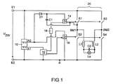
図1には、本発明による回路装置の実施例の略図が示されている。この回路装置には、第1入力端子E1と第2入力端子E2とが含まれており、これらの端子間に直流電圧が接続される。有利には、300〜400Vのオーダのいわゆる中間回路電圧が接続される。入力端子E1,E2間にはDC低電圧給電ユニット10が接続されており、この給電ユニットは、第1の出力側A1においてマイクロコントローラ12に5Vの直流電圧を供給し、また第2の出力側A2においてハイサイドドライバ14およびローサイドドライバ16に15Vの直流電圧を供給する。マイクロコントローラ12は、ローサイドドライバ16を直接駆動制御し、また電位分離ユニット18を介してハイサイドドライバを駆動制御する。
Claims (10)
- 高圧放電ランプ(La)を作動させるための回路装置であって、
該回路装置は、高圧放電ランプ用の作動回路を有しており、
該作動回路は、高圧放電ランプ(La)用のスイッチオン/スイッチオフ信号を受信するための入力側と、作動信号を高圧放電ランプ(La)に供給するための少なくとも1つの出力側とを有している、
形式の回路装置において、
前記の作動回路は、その入力側にてスイッチオフ信号を受信した後、前記の少なくとも1つの出力側に供給される前記の作動信号の出力(P)を低減するように構成されており、
前記の作動回路はさらに、前記の作動信号を、あらかじめ設定可能な出力閾値以上ではAC信号として供給し、当該のあらかじめ設定可能な出力閾値以下では擬似DC信号として供給するように構成されており、
前記の駆動制御回路(12)は、スイッチオフの際に最後の擬似DC動作中の極性を記憶するように構成されており、
前記の駆動制御回路(12)はさらに、前記の擬似DC動作に対する次のスイッチオフの際に他方の極性を使用するように構成されている、
ことを特徴とする、高圧放電ランプ(La)を作動させるための回路装置。 - 前記の作動回路には、少なくとも1つの第1電子スイッチ(S1)および第2電子スイッチ(S2)を有するブリッジ回路(20)が含まれており、
前記の作動回路にはさらに少なくとも前記の第1電子スイッチ(S1)および第2電子スイッチ(S2)用の駆動制御回路(14,16)が含まれており、
該駆動制御回路(14,16)は、少なくとも前記の第1電子スイッチ(S1)および第2電子スイッチ(S2)を、前記のブリッジ回路(20)の出力側に少なくとも前記のAC信号を供給するよう制御するように構成されている、
請求項1に記載の回路装置。 - 前記の作動回路には直流電圧源が含まれており、
当該作動回路は、前記のあらかじめ定めた出力閾値以下では前記の出力側と、前記の直流電源とを接続するように構成されている、
請求項1または2に記載の回路装置。 - 前記の駆動制御回路(14,16)はさらに、前記の少なくとも第1電子スイッチ(S1)および第2電子ステッチ(S2)を、前記のブリッジ回路(20)の出力側に前記の擬似DC信号も供給するよう制御するように構成されている、
請求項2に記載の回路装置。 - 前記の駆動制御回路(14,16)は、転流を時間的に短くすることによって、すなわち、いわゆる擬似転流によって前記の擬似DC信号を供給するように構成されている、
請求項4に記載の回路装置。 - 前記の駆動制御回路には、前記の少なくとも第1電子スイッチ(S1)および第2電子スイッチ(S2)に対してローサイドドライバ(16)およびハイサイドドライバ(14)が含まれており、
前記のローサイドドライバ(16)およびハイサイドドライバ(14)は、前記の各電子スイッチ(S1;S2)と接続するための1つずつの出力側と、制御装置(12)と接続するための1つずつの制御入力側と、給電電圧を接続するための端子に接続するための1つずつの給電端子とを有しており、
前記のハイサイドドライバ(14)にはコンデンサ(C1)が割り当てられて設けられており、
該コンデンサは、前記の第1電子スイッチ(S1)と第2電子スイッチ(S2)との間の中間点(BM1)と、前記の給電端子との間に接続されている、
請求項1から5までのいずれか1項に記載の回路装置。 - 前記の駆動制御回路(14;16)にはさらにダイオード(D1)が含まれており、
該ダイオードは、前記のコンデンサ(C1)から前記の給電電圧端子への電流が阻止されるように、前記のコンデンサ(C1)と前記の給電電圧端子との間に接続されている、
請求項6に記載の回路装置。 - 前記の駆動制御回路(14,16)は、50Hzと1kHzとの間の周波数、有利には500Hzの周波数で前記の擬似転流を行うように構成されている、
請求項5から7までのいずれか1項に記載の回路装置。 - さらに前記の駆動制御回路(14,16)には時間測定装置が含まれており、
前記の駆動制御回路(14,16)はさらに、前記の高圧放電ランプ(La)があらかじめ設定可能な出力の擬似DC信号で駆動されるあらかじめ設定した時間の経過後、前記の高圧放電ランプ(La)の動作を調整するように構成されている、
請求項1から8までのいずれか1項に記載の回路装置。 - 回路装置にて高圧放電ランプ(La)を作動させる方法であって、
前記の回路装置は、高圧放電ランプ(La)用の作動回路を有しており、
該作動回路は、前記の高圧放電ランプ(La)用のスイッチオン/スイッチオフ信号を受信するための入力側と、作動信号を前記の高圧放電ランプ(La)に供給するための少なくとも1つの出力側とを有している、
形式の方法において、
該方法は以下のステップ、すなわち、
a) 前記の作動回路の入力側にてスイッチオフ信号を受信するステップと、
b) 前記の作動回路の少なくとも1つの出力側に供給される作動信号の出力を低減するステップであって、この際、あらかじめ設定可能な出力閾値以上ではAC信号として、また当該のあらかじめ設定可能な出力閾値以下では擬似DC信号として前記の作動信号を供給するステップと、
を含み、
スイッチオフの際に最後の擬似DC動作中の極性が記憶され、
前記の擬似DC動作に対する次のスイッチオフの際に他方の極性が使用される、
ことを特徴とする、回路装置にて高圧放電ランプ(La)を作動させる方法。
Applications Claiming Priority (1)
| Application Number | Priority Date | Filing Date | Title |
|---|---|---|---|
| PCT/EP2007/062269 WO2009062542A1 (de) | 2007-11-13 | 2007-11-13 | Schaltungsanordnung und verfahren zum betreiben einer hochdruckentladungslampe |
Publications (2)
| Publication Number | Publication Date |
|---|---|
| JP2011503810A JP2011503810A (ja) | 2011-01-27 |
| JP5249342B2 true JP5249342B2 (ja) | 2013-07-31 |
Family
ID=39618828
Family Applications (1)
| Application Number | Title | Priority Date | Filing Date |
|---|---|---|---|
| JP2010533441A Expired - Fee Related JP5249342B2 (ja) | 2007-11-13 | 2007-11-13 | 高圧放電ランプを作動させるための回路装置および方法 |
Country Status (7)
| Country | Link |
|---|---|
| US (1) | US8593072B2 (ja) |
| EP (1) | EP2210454A1 (ja) |
| JP (1) | JP5249342B2 (ja) |
| KR (1) | KR20100098631A (ja) |
| CN (1) | CN101855945B (ja) |
| TW (1) | TW200932052A (ja) |
| WO (1) | WO2009062542A1 (ja) |
Families Citing this family (4)
| Publication number | Priority date | Publication date | Assignee | Title |
|---|---|---|---|---|
| US8901344B2 (en) | 2008-12-16 | 2014-12-02 | Basf Se | Production of carboxylic acid esters by stripping with alcohol vapor |
| US8472865B2 (en) * | 2010-08-12 | 2013-06-25 | Babak Taherloo | Echo light complex |
| CN103430628B (zh) | 2011-03-10 | 2016-01-13 | 皇家飞利浦有限公司 | 一种驱动气体放电灯的方法 |
| KR101360685B1 (ko) * | 2012-05-31 | 2014-02-10 | 엘지이노텍 주식회사 | 대기전력 절감 조명 시스템 |
Family Cites Families (28)
| Publication number | Priority date | Publication date | Assignee | Title |
|---|---|---|---|---|
| TW339496B (en) | 1994-06-22 | 1998-09-01 | Philips Electronics Nv | Method and circuit arrangement for operating a high-pressure discharge lamp |
| US5523405A (en) | 1995-03-14 | 1996-06-04 | E. I. Du Pont De Nemours And Company | Preparation of 4,6-dimethoxy-2-((phenoxycarbonyl)amino)-pyrimidine |
| US5932976A (en) | 1997-01-14 | 1999-08-03 | Matsushita Electric Works R&D Laboratory, Inc. | Discharge lamp driving |
| KR100664336B1 (ko) * | 1998-12-21 | 2007-01-02 | 코닌클리즈케 필립스 일렉트로닉스 엔.브이. | 회로 장치 |
| US6329761B1 (en) | 2000-06-30 | 2001-12-11 | Ebs International Corporation | Frequency controlled half-bridge inverter for variable loads |
| JP4070420B2 (ja) | 2001-03-23 | 2008-04-02 | フェニックス電機株式会社 | 超高圧放電灯の点灯方法と点灯装置 |
| US6717375B2 (en) | 2001-05-16 | 2004-04-06 | Matsushita Electric Industrial Co., Ltd. | Discharge lamp lighting device and system comprising it |
| JP3948233B2 (ja) | 2001-10-01 | 2007-07-25 | 株式会社村田製作所 | 積層型電子部品及びその製造方法 |
| DE10220509A1 (de) * | 2002-05-08 | 2003-11-20 | Philips Intellectual Property | Verfahren und Schaltungsanordnung zum Betrieb einer Hochdruckgasentladungslampe |
| CN1663325A (zh) * | 2002-06-25 | 2005-08-31 | 皇家飞利浦电子股份有限公司 | 气体放电灯的操作 |
| US7316483B2 (en) * | 2003-01-15 | 2008-01-08 | Koninklijke Philips Electronics N.V. | Method of representing a video image by means of a projector |
| JP3870914B2 (ja) | 2003-02-28 | 2007-01-24 | ウシオ電機株式会社 | エキシマランプ発光装置 |
| US7187244B2 (en) | 2003-03-03 | 2007-03-06 | International Rectifier Corporation | Digital light ballast oscillator |
| JP2004319193A (ja) | 2003-04-15 | 2004-11-11 | Phoenix Denki Kk | 高圧放電灯の点灯方法と点灯装置並びに該点灯装置用使用した映像機器 |
| JP4023413B2 (ja) * | 2003-07-28 | 2007-12-19 | 松下電工株式会社 | 高圧放電灯点灯装置 |
| JP4440614B2 (ja) * | 2003-12-05 | 2010-03-24 | フェニックス電機株式会社 | 高圧放電灯の点灯方法と点灯装置並びに該点灯装置を使用した映像機器 |
| EP1698214B1 (en) * | 2003-12-19 | 2008-03-12 | Philips Intellectual Property & Standards GmbH | Method and circuit arrangement for operating a discharge lamp |
| JP2005190766A (ja) * | 2003-12-25 | 2005-07-14 | Ushio Inc | 高圧放電ランプ点灯装置およびプロジェクター装置 |
| JP4448396B2 (ja) * | 2004-07-13 | 2010-04-07 | 株式会社日立製作所 | ランプ作動制御装置及びその方法 |
| KR20070044022A (ko) * | 2004-07-21 | 2007-04-26 | 코닌클리즈케 필립스 일렉트로닉스 엔.브이. | 전류 시에 동기화를 제공하는 램프 드라이버 |
| CN100576418C (zh) * | 2004-08-02 | 2009-12-30 | 优志旺电机株式会社 | 高压放电灯照明装置 |
| JP4990490B2 (ja) * | 2004-11-11 | 2012-08-01 | パナソニック株式会社 | 高圧放電ランプ点灯装置、高圧放電ランプ装置、投射型画像表示装置及び高圧放電ランプ点灯方法 |
| JP4711742B2 (ja) | 2005-05-26 | 2011-06-29 | フェニックス電機株式会社 | 高圧放電灯の点灯方法 |
| US7443103B2 (en) * | 2005-06-24 | 2008-10-28 | General Electric Company | High pressure lamp with lamp flicker suppression and lamp voltage control |
| US7323827B2 (en) * | 2005-12-29 | 2008-01-29 | General Electric Company | Ripple reduction method for electronic ballasts |
| JP2007214010A (ja) * | 2006-02-10 | 2007-08-23 | Seiko Epson Corp | 放電灯点灯装置及びプロジェクタ |
| CN101385400B (zh) | 2006-02-20 | 2012-09-26 | 皇家飞利浦电子股份有限公司 | 用于驱动气体放电灯的方法和驱动单元 |
| CN101536613B (zh) | 2006-12-13 | 2012-12-05 | 欧司朗股份有限公司 | 用于驱动放电灯的电路装置以及用于驱动放电灯的方法 |
-
2007
- 2007-11-13 JP JP2010533441A patent/JP5249342B2/ja not_active Expired - Fee Related
- 2007-11-13 US US12/742,447 patent/US8593072B2/en not_active Expired - Fee Related
- 2007-11-13 WO PCT/EP2007/062269 patent/WO2009062542A1/de not_active Ceased
- 2007-11-13 CN CN200780101538XA patent/CN101855945B/zh not_active Expired - Fee Related
- 2007-11-13 EP EP07822542A patent/EP2210454A1/de not_active Withdrawn
- 2007-11-13 KR KR1020107013096A patent/KR20100098631A/ko not_active Ceased
-
2008
- 2008-11-04 TW TW097142485A patent/TW200932052A/zh unknown
Also Published As
| Publication number | Publication date |
|---|---|
| JP2011503810A (ja) | 2011-01-27 |
| CN101855945A (zh) | 2010-10-06 |
| EP2210454A1 (de) | 2010-07-28 |
| TW200932052A (en) | 2009-07-16 |
| US20100270934A1 (en) | 2010-10-28 |
| WO2009062542A1 (de) | 2009-05-22 |
| CN101855945B (zh) | 2013-10-23 |
| US8593072B2 (en) | 2013-11-26 |
| KR20100098631A (ko) | 2010-09-08 |
Similar Documents
| Publication | Publication Date | Title |
|---|---|---|
| JP4052039B2 (ja) | 高圧放電ランプ点灯装置 | |
| JP5073682B2 (ja) | ガス放電ランプを駆動する方法及び駆動ユニット | |
| CN101686594B (zh) | 高压放电灯点亮装置和使用该高压放电灯点亮装置的灯具 | |
| JP5264713B2 (ja) | ランプの駆動回路 | |
| WO2004103032A1 (ja) | 高圧放電灯を点灯する装置および方法 | |
| WO2008001519A1 (en) | Electric discharge lamp device and lighting apparatus | |
| JP5249342B2 (ja) | 高圧放電ランプを作動させるための回路装置および方法 | |
| JP4438617B2 (ja) | 高圧放電ランプ用給電装置 | |
| CN1572125A (zh) | 用于操作放电灯的电路装置 | |
| US8664872B2 (en) | Circuit arrangement for operating a discharge lamp | |
| JP5262647B2 (ja) | 高圧放電灯点灯装置、プロジェクタ及び高圧放電灯の始動方法 | |
| JP4088816B2 (ja) | 点灯装置及び照明装置 | |
| JP4969583B2 (ja) | 放電灯点灯装置及びプロジェクタ | |
| JP5460065B2 (ja) | 放電灯点灯回路 | |
| EP1897418A2 (en) | Method for driving an inverter of a gas discharge supply circuit | |
| JP2011505659A (ja) | ガス放電ランプを点火する方法及び点火装置 | |
| JP4460106B2 (ja) | 高圧放電ランプの点灯方法 | |
| CN101982020B (zh) | 用于操作hid放电灯的电路结构 | |
| JP2010080137A (ja) | 高圧放電灯点灯装置、照明器具 | |
| JP2010080138A (ja) | 高圧放電灯点灯装置、照明器具 | |
| JP2005100786A (ja) | 放電灯点灯装置 | |
| JP2013201030A (ja) | 高圧放電ランプ点灯装置及びそれを用いたプロジェクタ | |
| US8917036B1 (en) | Method and apparatus for dimming high intensity discharge lamps | |
| JP2002237393A (ja) | 放電灯点灯装置 | |
| KR200179879Y1 (ko) | 고압방전 램프용 안정기의 시리즈형 이그나이터 |
Legal Events
| Date | Code | Title | Description |
|---|---|---|---|
| RD04 | Notification of resignation of power of attorney |
Free format text: JAPANESE INTERMEDIATE CODE: A7424 Effective date: 20101228 |
|
| A977 | Report on retrieval |
Free format text: JAPANESE INTERMEDIATE CODE: A971007 Effective date: 20120309 |
|
| A131 | Notification of reasons for refusal |
Free format text: JAPANESE INTERMEDIATE CODE: A131 Effective date: 20120328 |
|
| A601 | Written request for extension of time |
Free format text: JAPANESE INTERMEDIATE CODE: A601 Effective date: 20120625 |
|
| A602 | Written permission of extension of time |
Free format text: JAPANESE INTERMEDIATE CODE: A602 Effective date: 20120702 |
|
| A601 | Written request for extension of time |
Free format text: JAPANESE INTERMEDIATE CODE: A601 Effective date: 20120726 |
|
| A602 | Written permission of extension of time |
Free format text: JAPANESE INTERMEDIATE CODE: A602 Effective date: 20120802 |
|
| A601 | Written request for extension of time |
Free format text: JAPANESE INTERMEDIATE CODE: A601 Effective date: 20120827 |
|
| A602 | Written permission of extension of time |
Free format text: JAPANESE INTERMEDIATE CODE: A602 Effective date: 20120903 |
|
| A521 | Request for written amendment filed |
Free format text: JAPANESE INTERMEDIATE CODE: A523 Effective date: 20120921 |
|
| TRDD | Decision of grant or rejection written | ||
| A01 | Written decision to grant a patent or to grant a registration (utility model) |
Free format text: JAPANESE INTERMEDIATE CODE: A01 Effective date: 20130313 |
|
| A61 | First payment of annual fees (during grant procedure) |
Free format text: JAPANESE INTERMEDIATE CODE: A61 Effective date: 20130411 |
|
| R150 | Certificate of patent or registration of utility model |
Free format text: JAPANESE INTERMEDIATE CODE: R150 |
|
| FPAY | Renewal fee payment (event date is renewal date of database) |
Free format text: PAYMENT UNTIL: 20160419 Year of fee payment: 3 |
|
| LAPS | Cancellation because of no payment of annual fees |