JP5153640B2 - 自動車の座席のレールをロックするための機構 - Google Patents
自動車の座席のレールをロックするための機構 Download PDFInfo
- Publication number
- JP5153640B2 JP5153640B2 JP2008541793A JP2008541793A JP5153640B2 JP 5153640 B2 JP5153640 B2 JP 5153640B2 JP 2008541793 A JP2008541793 A JP 2008541793A JP 2008541793 A JP2008541793 A JP 2008541793A JP 5153640 B2 JP5153640 B2 JP 5153640B2
- Authority
- JP
- Japan
- Prior art keywords
- rail
- seat
- crossbar
- protrusion
- locking mechanism
- Prior art date
- Legal status (The legal status is an assumption and is not a legal conclusion. Google has not performed a legal analysis and makes no representation as to the accuracy of the status listed.)
- Expired - Fee Related
Links
Images


Classifications
-
- B—PERFORMING OPERATIONS; TRANSPORTING
- B60—VEHICLES IN GENERAL
- B60N—SEATS SPECIALLY ADAPTED FOR VEHICLES; VEHICLE PASSENGER ACCOMMODATION NOT OTHERWISE PROVIDED FOR
- B60N2/00—Seats specially adapted for vehicles; Arrangement or mounting of seats in vehicles
- B60N2/02—Seats specially adapted for vehicles; Arrangement or mounting of seats in vehicles the seat or part thereof being movable, e.g. adjustable
- B60N2/04—Seats specially adapted for vehicles; Arrangement or mounting of seats in vehicles the seat or part thereof being movable, e.g. adjustable the whole seat being movable
- B60N2/06—Seats specially adapted for vehicles; Arrangement or mounting of seats in vehicles the seat or part thereof being movable, e.g. adjustable the whole seat being movable slidable
- B60N2/08—Seats specially adapted for vehicles; Arrangement or mounting of seats in vehicles the seat or part thereof being movable, e.g. adjustable the whole seat being movable slidable characterised by the locking device
- B60N2/0831—Movement of the latch
- B60N2/0862—Movement of the latch sliding
- B60N2/0875—Movement of the latch sliding in a vertical direction
-
- B—PERFORMING OPERATIONS; TRANSPORTING
- B60—VEHICLES IN GENERAL
- B60N—SEATS SPECIALLY ADAPTED FOR VEHICLES; VEHICLE PASSENGER ACCOMMODATION NOT OTHERWISE PROVIDED FOR
- B60N2/00—Seats specially adapted for vehicles; Arrangement or mounting of seats in vehicles
- B60N2/02—Seats specially adapted for vehicles; Arrangement or mounting of seats in vehicles the seat or part thereof being movable, e.g. adjustable
- B60N2/04—Seats specially adapted for vehicles; Arrangement or mounting of seats in vehicles the seat or part thereof being movable, e.g. adjustable the whole seat being movable
- B60N2/06—Seats specially adapted for vehicles; Arrangement or mounting of seats in vehicles the seat or part thereof being movable, e.g. adjustable the whole seat being movable slidable
- B60N2/07—Slide construction
-
- B—PERFORMING OPERATIONS; TRANSPORTING
- B60—VEHICLES IN GENERAL
- B60N—SEATS SPECIALLY ADAPTED FOR VEHICLES; VEHICLE PASSENGER ACCOMMODATION NOT OTHERWISE PROVIDED FOR
- B60N2/00—Seats specially adapted for vehicles; Arrangement or mounting of seats in vehicles
- B60N2/02—Seats specially adapted for vehicles; Arrangement or mounting of seats in vehicles the seat or part thereof being movable, e.g. adjustable
- B60N2/04—Seats specially adapted for vehicles; Arrangement or mounting of seats in vehicles the seat or part thereof being movable, e.g. adjustable the whole seat being movable
- B60N2/06—Seats specially adapted for vehicles; Arrangement or mounting of seats in vehicles the seat or part thereof being movable, e.g. adjustable the whole seat being movable slidable
- B60N2/08—Seats specially adapted for vehicles; Arrangement or mounting of seats in vehicles the seat or part thereof being movable, e.g. adjustable the whole seat being movable slidable characterised by the locking device
- B60N2/0881—Activation of the latches by the control mechanism
Description
− 第1クロスバーの戻り機構が金属ストリップであり、該金属ストリップの第1端部が第2レールに固定して取り付けられ、第2端部が、第1レールにおける座席の位置の指標となる少なくとも1つの突起を備える。
− 第2クロスバーの第1突出部が第1クロスバーに溶接されている。
− 第1クロスバーと第2クロスバーが、ピボットリンクを形成している同一の回転軸に固定して取り付けられている。
− 第2クロスバーの第1突出部が、第1クロスバー上を滑動する。
− 第2クロスバーが第1クロスバーの回転軸とは異なる回転軸に接続され、これにより後方の第2突出部の運動範囲を減少させることができる。
− 第2レール上に取り付けられた少なくとも1つの金属ケーシングにより、第2クロスバーの運動範囲が守られる。
本発明はまた、上記のロック機構を備える自動車の座席に関するものである。
Claims (4)
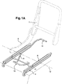
- 自動車の座席(2)のレールのロック機構(1)であって、
車両の縦軸に沿って構造要素(4)に接続されている第1レール(3)と、
第1レール(3)内を滑動し、座席(2)の基台フレーム(6)を支持する第2レール(5)と、
第1レール(3)と第2レール(5)の2つの同軸のレールに垂直な軸に沿って、第2レール(5)において旋回する第1クロスバー(7)であって、第1クロスバー(7)の戻り機構(8)が第2レール(5)を第1レール(3)上の所望の位置で保持する、第1クロスバー(7)と、
を備え、
第2クロスバー(9)が、座席(2)の前方に向いている第1突出部(10)と座席(2)の後方に向いている第2突出部(11)とを含み、座席(2)の縦方向の移動が2つの突出部(10、11)を介して制御されるように、第2クロスバー(9)が第1クロスバー(7)に接続され、
第2クロスバー(9)の第1突出部(10)が第1クロスバー(7)上を滑動し、
第2クロスバー(9)が第1クロスバー(7)の回転軸とは異なる回転軸(13)に接続され、これにより後方の第2突出部(11)の運動範囲を減少させることができる
ことを特徴とする、自動車の座席(2)のレールのロック機構(1)。 - 第1クロスバー(7)の戻り機構(8)が金属ストリップであり、金属ストリップの第1端部が第2レール(5)に固定して取り付けられ、第2端部が、第1レール(3)における座席(2)の位置の指標となる、少なくとも1つの突起を備えることを特徴とする、請求項1に記載のロック機構(1)。
- 第2レール(5)上に取り付けられた少なくとも1つの金属ケーシング(14)により、第2クロスバー(9)の運動範囲が守られることを特徴とする、請求項1又は2に記載のロック機構(1)。
- 請求項1ないし3のいずれか1項に記載のロック機構(1)を備える自動車の座席(2)。
Applications Claiming Priority (3)
| Application Number | Priority Date | Filing Date | Title |
|---|---|---|---|
| FR0553515A FR2893555B1 (fr) | 2005-11-21 | 2005-11-21 | Mecanisme de verrouillage des glissieres d'un siege de vehicule automobile |
| FR0553515 | 2005-11-21 | ||
| PCT/FR2006/051095 WO2007057590A1 (fr) | 2005-11-21 | 2006-10-24 | Mecanisme de verrouillage des glissieres d'un siege de vehicule automobile |
Publications (2)
| Publication Number | Publication Date |
|---|---|
| JP2009516619A JP2009516619A (ja) | 2009-04-23 |
| JP5153640B2 true JP5153640B2 (ja) | 2013-02-27 |
Family
ID=36782590
Family Applications (1)
| Application Number | Title | Priority Date | Filing Date |
|---|---|---|---|
| JP2008541793A Expired - Fee Related JP5153640B2 (ja) | 2005-11-21 | 2006-10-24 | 自動車の座席のレールをロックするための機構 |
Country Status (12)
| Country | Link |
|---|---|
| US (1) | US8079564B2 (ja) |
| EP (1) | EP1951543B1 (ja) |
| JP (1) | JP5153640B2 (ja) |
| KR (1) | KR20080069200A (ja) |
| CN (1) | CN101312848B (ja) |
| AT (1) | ATE461070T1 (ja) |
| BR (1) | BRPI0618858A2 (ja) |
| DE (1) | DE602006013027D1 (ja) |
| ES (1) | ES2342561T3 (ja) |
| FR (1) | FR2893555B1 (ja) |
| RU (1) | RU2381918C1 (ja) |
| WO (1) | WO2007057590A1 (ja) |
Families Citing this family (3)
| Publication number | Priority date | Publication date | Assignee | Title |
|---|---|---|---|---|
| DE102008041857B4 (de) * | 2008-09-08 | 2020-08-27 | Volkswagen Ag | Fahrzeugsitz mit einer vorderen und einer hinteren Handhabe zur Sitzlängsverstellung |
| US9821683B2 (en) * | 2015-05-22 | 2017-11-21 | AISIN Technical Center of America, Inc. | Easy seat positioning and installation |
| DE102017007844B4 (de) * | 2017-08-18 | 2022-01-05 | Audi Ag | Fahrzeugsitz für ein Kraftfahrzeug und Kraftfahrzeug |
Family Cites Families (15)
| Publication number | Priority date | Publication date | Assignee | Title |
|---|---|---|---|---|
| DE2232117C3 (de) * | 1972-06-30 | 1980-10-02 | Bremshey Ag, 5650 Solingen | Höhen- und neigungsverstellbarer Fahrzeugsitz |
| JPS49110411U (ja) * | 1973-01-19 | 1974-09-20 | ||
| JPS5935235U (ja) * | 1982-08-31 | 1984-03-05 | 株式会社タチエス | シ−トアジヤスタ |
| JPS6032135U (ja) * | 1983-08-12 | 1985-03-05 | 関東自動車工業株式会社 | 乗用自動車のフロントシ−ト |
| FR2623451B1 (fr) * | 1987-11-20 | 1990-04-06 | Cousin Cie Ets A & M Freres | Glissieres a vis sans fin reversibles permettant un deplacement micro-millimetrique et comportant une memoire pour siege de vehicule |
| FR2691681B1 (fr) * | 1992-05-26 | 1994-07-08 | Renault | Siege arriere de vehicule automobile a deux rangees de sieges reglables. |
| JP3269208B2 (ja) * | 1993-09-22 | 2002-03-25 | アイシン精機株式会社 | シートのスライド装置 |
| FR2736311B1 (fr) * | 1995-07-04 | 1997-09-05 | Faure Bertrand Equipements Sa | Glissiere verrouillable en position pour sieges de vehicules automobiles |
| US5730412A (en) * | 1996-02-09 | 1998-03-24 | Shrock Manufacturing, Inc. | Locking adjustable seat |
| JP4005681B2 (ja) * | 1997-12-08 | 2007-11-07 | デルタ工業株式会社 | シートのスライドロック装置 |
| CN2369898Y (zh) * | 1999-04-24 | 2000-03-22 | 中外合资常州华阳汽车附件有限公司 | 汽车座椅移动及锁紧装置 |
| JP4465835B2 (ja) * | 2000-08-28 | 2010-05-26 | アイシン精機株式会社 | 車両用シート装置 |
| JP2004123001A (ja) * | 2002-10-04 | 2004-04-22 | Kanto Auto Works Ltd | 車両用シートアジャスタ |
| FR2853865B1 (fr) * | 2003-04-17 | 2005-06-24 | Faurecia Sieges Automobile | Glissiere pour siege de vehicule |
| DE10342724B4 (de) * | 2003-09-16 | 2005-07-28 | Faurecia Autositze Gmbh & Co. Kg | Kraftfahrzeugsitz |
-
2005
- 2005-11-21 FR FR0553515A patent/FR2893555B1/fr not_active Expired - Fee Related
-
2006
- 2006-10-24 KR KR1020087012042A patent/KR20080069200A/ko not_active Application Discontinuation
- 2006-10-24 US US12/094,081 patent/US8079564B2/en not_active Expired - Fee Related
- 2006-10-24 RU RU2008125120/11A patent/RU2381918C1/ru active
- 2006-10-24 AT AT06831289T patent/ATE461070T1/de not_active IP Right Cessation
- 2006-10-24 DE DE602006013027T patent/DE602006013027D1/de active Active
- 2006-10-24 JP JP2008541793A patent/JP5153640B2/ja not_active Expired - Fee Related
- 2006-10-24 WO PCT/FR2006/051095 patent/WO2007057590A1/fr active Application Filing
- 2006-10-24 BR BRPI0618858A patent/BRPI0618858A2/pt not_active IP Right Cessation
- 2006-10-24 ES ES06831289T patent/ES2342561T3/es active Active
- 2006-10-24 EP EP06831289A patent/EP1951543B1/fr not_active Not-in-force
- 2006-10-24 CN CN2006800431519A patent/CN101312848B/zh not_active Expired - Fee Related
Also Published As
| Publication number | Publication date |
|---|---|
| US20090218468A1 (en) | 2009-09-03 |
| KR20080069200A (ko) | 2008-07-25 |
| US8079564B2 (en) | 2011-12-20 |
| FR2893555A1 (fr) | 2007-05-25 |
| RU2008125120A (ru) | 2009-12-27 |
| EP1951543B1 (fr) | 2010-03-17 |
| CN101312848B (zh) | 2010-12-08 |
| CN101312848A (zh) | 2008-11-26 |
| JP2009516619A (ja) | 2009-04-23 |
| FR2893555B1 (fr) | 2008-01-04 |
| DE602006013027D1 (de) | 2010-04-29 |
| ES2342561T3 (es) | 2010-07-08 |
| WO2007057590A1 (fr) | 2007-05-24 |
| BRPI0618858A2 (pt) | 2016-09-13 |
| ATE461070T1 (de) | 2010-04-15 |
| EP1951543A1 (fr) | 2008-08-06 |
| RU2381918C1 (ru) | 2010-02-20 |
Similar Documents
| Publication | Publication Date | Title |
|---|---|---|
| JP5193553B2 (ja) | 誤操作防止機構及び車両用格納シート | |
| JP4420603B2 (ja) | 乗降し易い中央位置メモリ付きシートアジャスター | |
| JP4850750B2 (ja) | 車両用シート | |
| EP1829736B1 (en) | Automobile seat | |
| JP5431422B2 (ja) | 車両用シート | |
| WO2014192824A1 (ja) | 車両用シート | |
| CN102227335A (zh) | 用于座椅轨道的内部全记忆模块 | |
| JP5109543B2 (ja) | 乗物用シート | |
| KR101607103B1 (ko) | 진입 간편화 기능을 갖는 차량 시트용 잠금 해제 장치 및 잠금 해제 장치의 작동 방법 | |
| JP2011105042A (ja) | 車両用シート装置 | |
| US6786552B2 (en) | Catch hook for a backrest adjustment armature in the seats of motor vehicles | |
| JP5153640B2 (ja) | 自動車の座席のレールをロックするための機構 | |
| JP4580835B2 (ja) | 車両用シートのシートバック前倒し機構 | |
| JP2011255860A (ja) | 自動車のシートバックの支持構造 | |
| JP2008273445A (ja) | 車両用ヘッドレスト傾動装置 | |
| KR101143984B1 (ko) | 자동차의 리어시트 리클라이너 작동장치 | |
| JP4480167B2 (ja) | ウォークインシート構造 | |
| JPH09207637A (ja) | 車両用シートの収納構造 | |
| JP6582508B2 (ja) | 車両用シート | |
| JP5365354B2 (ja) | 車両用シート | |
| JP5507529B2 (ja) | 車両用荷室内構造 | |
| JP3140263B2 (ja) | 格納式ヘッドレスト構造 | |
| JP2017165130A (ja) | 車両用シート装置 | |
| JP3122810B2 (ja) | シートスライド制御装置 | |
| JP2006015021A (ja) | 車両用可倒式ヘッドレスト |
Legal Events
| Date | Code | Title | Description |
|---|---|---|---|
| A621 | Written request for application examination |
Free format text: JAPANESE INTERMEDIATE CODE: A621 Effective date: 20091015 |
|
| A131 | Notification of reasons for refusal |
Free format text: JAPANESE INTERMEDIATE CODE: A131 Effective date: 20120411 |
|
| A601 | Written request for extension of time |
Free format text: JAPANESE INTERMEDIATE CODE: A601 Effective date: 20120710 |
|
| A602 | Written permission of extension of time |
Free format text: JAPANESE INTERMEDIATE CODE: A602 Effective date: 20120718 |
|
| A521 | Request for written amendment filed |
Free format text: JAPANESE INTERMEDIATE CODE: A523 Effective date: 20120720 |
|
| TRDD | Decision of grant or rejection written | ||
| A01 | Written decision to grant a patent or to grant a registration (utility model) |
Free format text: JAPANESE INTERMEDIATE CODE: A01 Effective date: 20121106 |
|
| A61 | First payment of annual fees (during grant procedure) |
Free format text: JAPANESE INTERMEDIATE CODE: A61 Effective date: 20121204 |
|
| FPAY | Renewal fee payment (event date is renewal date of database) |
Free format text: PAYMENT UNTIL: 20151214 Year of fee payment: 3 |
|
| R150 | Certificate of patent or registration of utility model |
Ref document number: 5153640 Country of ref document: JP Free format text: JAPANESE INTERMEDIATE CODE: R150 Free format text: JAPANESE INTERMEDIATE CODE: R150 |
|
| R250 | Receipt of annual fees |
Free format text: JAPANESE INTERMEDIATE CODE: R250 |
|
| R250 | Receipt of annual fees |
Free format text: JAPANESE INTERMEDIATE CODE: R250 |
|
| R250 | Receipt of annual fees |
Free format text: JAPANESE INTERMEDIATE CODE: R250 |
|
| R250 | Receipt of annual fees |
Free format text: JAPANESE INTERMEDIATE CODE: R250 |
|
| R250 | Receipt of annual fees |
Free format text: JAPANESE INTERMEDIATE CODE: R250 |
|
| R250 | Receipt of annual fees |
Free format text: JAPANESE INTERMEDIATE CODE: R250 |
|
| R250 | Receipt of annual fees |
Free format text: JAPANESE INTERMEDIATE CODE: R250 |
|
| LAPS | Cancellation because of no payment of annual fees |