EP4530004A2 - Formvorrichtung und formverfahren - Google Patents
Formvorrichtung und formverfahren Download PDFInfo
- Publication number
- EP4530004A2 EP4530004A2 EP25156731.9A EP25156731A EP4530004A2 EP 4530004 A2 EP4530004 A2 EP 4530004A2 EP 25156731 A EP25156731 A EP 25156731A EP 4530004 A2 EP4530004 A2 EP 4530004A2
- Authority
- EP
- European Patent Office
- Prior art keywords
- shaping
- optical system
- condensing optical
- area
- workpiece
- Prior art date
- Legal status (The legal status is an assumption and is not a legal conclusion. Google has not performed a legal analysis and makes no representation as to the accuracy of the status listed.)
- Pending
Links
Images


Classifications
-
- B—PERFORMING OPERATIONS; TRANSPORTING
- B22—CASTING; POWDER METALLURGY
- B22F—WORKING METALLIC POWDER; MANUFACTURE OF ARTICLES FROM METALLIC POWDER; MAKING METALLIC POWDER; APPARATUS OR DEVICES SPECIALLY ADAPTED FOR METALLIC POWDER
- B22F12/00—Apparatus or devices specially adapted for additive manufacturing; Auxiliary means for additive manufacturing; Combinations of additive manufacturing apparatus or devices with other processing apparatus or devices
- B22F12/22—Driving means
-
- B—PERFORMING OPERATIONS; TRANSPORTING
- B22—CASTING; POWDER METALLURGY
- B22F—WORKING METALLIC POWDER; MANUFACTURE OF ARTICLES FROM METALLIC POWDER; MAKING METALLIC POWDER; APPARATUS OR DEVICES SPECIALLY ADAPTED FOR METALLIC POWDER
- B22F12/00—Apparatus or devices specially adapted for additive manufacturing; Auxiliary means for additive manufacturing; Combinations of additive manufacturing apparatus or devices with other processing apparatus or devices
- B22F12/40—Radiation means
- B22F12/44—Radiation means characterised by the configuration of the radiation means
- B22F12/45—Two or more
-
- B—PERFORMING OPERATIONS; TRANSPORTING
- B22—CASTING; POWDER METALLURGY
- B22F—WORKING METALLIC POWDER; MANUFACTURE OF ARTICLES FROM METALLIC POWDER; MAKING METALLIC POWDER; APPARATUS OR DEVICES SPECIALLY ADAPTED FOR METALLIC POWDER
- B22F12/00—Apparatus or devices specially adapted for additive manufacturing; Auxiliary means for additive manufacturing; Combinations of additive manufacturing apparatus or devices with other processing apparatus or devices
- B22F12/50—Means for feeding of material, e.g. heads
- B22F12/53—Nozzles
-
- B—PERFORMING OPERATIONS; TRANSPORTING
- B23—MACHINE TOOLS; METAL-WORKING NOT OTHERWISE PROVIDED FOR
- B23K—SOLDERING OR UNSOLDERING; WELDING; CLADDING OR PLATING BY SOLDERING OR WELDING; CUTTING BY APPLYING HEAT LOCALLY, e.g. FLAME CUTTING; WORKING BY LASER BEAM
- B23K26/00—Working by laser beam, e.g. welding, cutting or boring
- B23K26/02—Positioning or observing the workpiece, e.g. with respect to the point of impact; Aligning, aiming or focusing the laser beam
- B23K26/06—Shaping the laser beam, e.g. by masks or multi-focusing
- B23K26/062—Shaping the laser beam, e.g. by masks or multi-focusing by direct control of the laser beam
- B23K26/0626—Energy control of the laser beam
-
- B—PERFORMING OPERATIONS; TRANSPORTING
- B23—MACHINE TOOLS; METAL-WORKING NOT OTHERWISE PROVIDED FOR
- B23K—SOLDERING OR UNSOLDERING; WELDING; CLADDING OR PLATING BY SOLDERING OR WELDING; CUTTING BY APPLYING HEAT LOCALLY, e.g. FLAME CUTTING; WORKING BY LASER BEAM
- B23K26/00—Working by laser beam, e.g. welding, cutting or boring
- B23K26/02—Positioning or observing the workpiece, e.g. with respect to the point of impact; Aligning, aiming or focusing the laser beam
- B23K26/06—Shaping the laser beam, e.g. by masks or multi-focusing
- B23K26/0665—Shaping the laser beam, e.g. by masks or multi-focusing by beam condensation on the workpiece, e.g. for focusing
-
- B—PERFORMING OPERATIONS; TRANSPORTING
- B23—MACHINE TOOLS; METAL-WORKING NOT OTHERWISE PROVIDED FOR
- B23K—SOLDERING OR UNSOLDERING; WELDING; CLADDING OR PLATING BY SOLDERING OR WELDING; CUTTING BY APPLYING HEAT LOCALLY, e.g. FLAME CUTTING; WORKING BY LASER BEAM
- B23K26/00—Working by laser beam, e.g. welding, cutting or boring
- B23K26/08—Devices involving relative movement between laser beam and workpiece
- B23K26/0823—Devices involving rotation of the workpiece
-
- B—PERFORMING OPERATIONS; TRANSPORTING
- B23—MACHINE TOOLS; METAL-WORKING NOT OTHERWISE PROVIDED FOR
- B23K—SOLDERING OR UNSOLDERING; WELDING; CLADDING OR PLATING BY SOLDERING OR WELDING; CUTTING BY APPLYING HEAT LOCALLY, e.g. FLAME CUTTING; WORKING BY LASER BEAM
- B23K26/00—Working by laser beam, e.g. welding, cutting or boring
- B23K26/08—Devices involving relative movement between laser beam and workpiece
- B23K26/0869—Devices involving movement of the laser head in at least one axial direction
- B23K26/0876—Devices involving movement of the laser head in at least one axial direction in at least two axial directions
-
- B—PERFORMING OPERATIONS; TRANSPORTING
- B23—MACHINE TOOLS; METAL-WORKING NOT OTHERWISE PROVIDED FOR
- B23K—SOLDERING OR UNSOLDERING; WELDING; CLADDING OR PLATING BY SOLDERING OR WELDING; CUTTING BY APPLYING HEAT LOCALLY, e.g. FLAME CUTTING; WORKING BY LASER BEAM
- B23K26/00—Working by laser beam, e.g. welding, cutting or boring
- B23K26/14—Working by laser beam, e.g. welding, cutting or boring using a fluid stream, e.g. a jet of gas, in conjunction with the laser beam; Nozzles therefor
- B23K26/144—Working by laser beam, e.g. welding, cutting or boring using a fluid stream, e.g. a jet of gas, in conjunction with the laser beam; Nozzles therefor the fluid stream containing particles, e.g. powder
-
- B—PERFORMING OPERATIONS; TRANSPORTING
- B23—MACHINE TOOLS; METAL-WORKING NOT OTHERWISE PROVIDED FOR
- B23K—SOLDERING OR UNSOLDERING; WELDING; CLADDING OR PLATING BY SOLDERING OR WELDING; CUTTING BY APPLYING HEAT LOCALLY, e.g. FLAME CUTTING; WORKING BY LASER BEAM
- B23K26/00—Working by laser beam, e.g. welding, cutting or boring
- B23K26/34—Laser welding for purposes other than joining
- B23K26/342—Build-up welding
-
- B—PERFORMING OPERATIONS; TRANSPORTING
- B33—ADDITIVE MANUFACTURING TECHNOLOGY
- B33Y—ADDITIVE MANUFACTURING, i.e. MANUFACTURING OF THREE-DIMENSIONAL [3-D] OBJECTS BY ADDITIVE DEPOSITION, ADDITIVE AGGLOMERATION OR ADDITIVE LAYERING, e.g. BY 3-D PRINTING, STEREOLITHOGRAPHY OR SELECTIVE LASER SINTERING
- B33Y10/00—Processes of additive manufacturing
-
- B—PERFORMING OPERATIONS; TRANSPORTING
- B33—ADDITIVE MANUFACTURING TECHNOLOGY
- B33Y—ADDITIVE MANUFACTURING, i.e. MANUFACTURING OF THREE-DIMENSIONAL [3-D] OBJECTS BY ADDITIVE DEPOSITION, ADDITIVE AGGLOMERATION OR ADDITIVE LAYERING, e.g. BY 3-D PRINTING, STEREOLITHOGRAPHY OR SELECTIVE LASER SINTERING
- B33Y30/00—Apparatus for additive manufacturing; Details thereof or accessories therefor
-
- B—PERFORMING OPERATIONS; TRANSPORTING
- B33—ADDITIVE MANUFACTURING TECHNOLOGY
- B33Y—ADDITIVE MANUFACTURING, i.e. MANUFACTURING OF THREE-DIMENSIONAL [3-D] OBJECTS BY ADDITIVE DEPOSITION, ADDITIVE AGGLOMERATION OR ADDITIVE LAYERING, e.g. BY 3-D PRINTING, STEREOLITHOGRAPHY OR SELECTIVE LASER SINTERING
- B33Y50/00—Data acquisition or data processing for additive manufacturing
- B33Y50/02—Data acquisition or data processing for additive manufacturing for controlling or regulating additive manufacturing processes
-
- B—PERFORMING OPERATIONS; TRANSPORTING
- B22—CASTING; POWDER METALLURGY
- B22F—WORKING METALLIC POWDER; MANUFACTURE OF ARTICLES FROM METALLIC POWDER; MAKING METALLIC POWDER; APPARATUS OR DEVICES SPECIALLY ADAPTED FOR METALLIC POWDER
- B22F10/00—Additive manufacturing of workpieces or articles from metallic powder
- B22F10/20—Direct sintering or melting
- B22F10/25—Direct deposition of metal particles, e.g. direct metal deposition [DMD] or laser engineered net shaping [LENS]
-
- B—PERFORMING OPERATIONS; TRANSPORTING
- B22—CASTING; POWDER METALLURGY
- B22F—WORKING METALLIC POWDER; MANUFACTURE OF ARTICLES FROM METALLIC POWDER; MAKING METALLIC POWDER; APPARATUS OR DEVICES SPECIALLY ADAPTED FOR METALLIC POWDER
- B22F10/00—Additive manufacturing of workpieces or articles from metallic powder
- B22F10/30—Process control
- B22F10/36—Process control of energy beam parameters
- B22F10/362—Process control of energy beam parameters for preheating
-
- B—PERFORMING OPERATIONS; TRANSPORTING
- B22—CASTING; POWDER METALLURGY
- B22F—WORKING METALLIC POWDER; MANUFACTURE OF ARTICLES FROM METALLIC POWDER; MAKING METALLIC POWDER; APPARATUS OR DEVICES SPECIALLY ADAPTED FOR METALLIC POWDER
- B22F10/00—Additive manufacturing of workpieces or articles from metallic powder
- B22F10/60—Treatment of workpieces or articles after build-up
- B22F10/66—Treatment of workpieces or articles after build-up by mechanical means
-
- B—PERFORMING OPERATIONS; TRANSPORTING
- B22—CASTING; POWDER METALLURGY
- B22F—WORKING METALLIC POWDER; MANUFACTURE OF ARTICLES FROM METALLIC POWDER; MAKING METALLIC POWDER; APPARATUS OR DEVICES SPECIALLY ADAPTED FOR METALLIC POWDER
- B22F12/00—Apparatus or devices specially adapted for additive manufacturing; Auxiliary means for additive manufacturing; Combinations of additive manufacturing apparatus or devices with other processing apparatus or devices
- B22F12/40—Radiation means
- B22F12/41—Radiation means characterised by the type, e.g. laser or electron beam
-
- B—PERFORMING OPERATIONS; TRANSPORTING
- B22—CASTING; POWDER METALLURGY
- B22F—WORKING METALLIC POWDER; MANUFACTURE OF ARTICLES FROM METALLIC POWDER; MAKING METALLIC POWDER; APPARATUS OR DEVICES SPECIALLY ADAPTED FOR METALLIC POWDER
- B22F12/00—Apparatus or devices specially adapted for additive manufacturing; Auxiliary means for additive manufacturing; Combinations of additive manufacturing apparatus or devices with other processing apparatus or devices
- B22F12/90—Means for process control, e.g. cameras or sensors
-
- B—PERFORMING OPERATIONS; TRANSPORTING
- B22—CASTING; POWDER METALLURGY
- B22F—WORKING METALLIC POWDER; MANUFACTURE OF ARTICLES FROM METALLIC POWDER; MAKING METALLIC POWDER; APPARATUS OR DEVICES SPECIALLY ADAPTED FOR METALLIC POWDER
- B22F3/00—Manufacture of workpieces or articles from metallic powder characterised by the manner of compacting or sintering; Apparatus specially adapted therefor ; Presses and furnaces
- B22F3/24—After-treatment of workpieces or articles
- B22F2003/247—Removing material: carving, cleaning, grinding, hobbing, honing, lapping, polishing, milling, shaving, skiving, turning the surface
-
- G—PHYSICS
- G02—OPTICS
- G02B—OPTICAL ELEMENTS, SYSTEMS OR APPARATUS
- G02B26/00—Optical devices or arrangements for the control of light using movable or deformable optical elements
-
- G—PHYSICS
- G02—OPTICS
- G02F—OPTICAL DEVICES OR ARRANGEMENTS FOR THE CONTROL OF LIGHT BY MODIFICATION OF THE OPTICAL PROPERTIES OF THE MEDIA OF THE ELEMENTS INVOLVED THEREIN; NON-LINEAR OPTICS; FREQUENCY-CHANGING OF LIGHT; OPTICAL LOGIC ELEMENTS; OPTICAL ANALOGUE/DIGITAL CONVERTERS
- G02F2203/00—Function characteristic
- G02F2203/12—Function characteristic spatial light modulator
-
- Y—GENERAL TAGGING OF NEW TECHNOLOGICAL DEVELOPMENTS; GENERAL TAGGING OF CROSS-SECTIONAL TECHNOLOGIES SPANNING OVER SEVERAL SECTIONS OF THE IPC; TECHNICAL SUBJECTS COVERED BY FORMER USPC CROSS-REFERENCE ART COLLECTIONS [XRACs] AND DIGESTS
- Y02—TECHNOLOGIES OR APPLICATIONS FOR MITIGATION OR ADAPTATION AGAINST CLIMATE CHANGE
- Y02P—CLIMATE CHANGE MITIGATION TECHNOLOGIES IN THE PRODUCTION OR PROCESSING OF GOODS
- Y02P10/00—Technologies related to metal processing
- Y02P10/25—Process efficiency
Definitions
- the present invention relates to a shaping apparatus and a shaping method, and more particularly to a shaping apparatus and a shaping method to form a three-dimensional shaped object on a target surface.
- the shaping apparatus and the shaping method related to the present invention can be suitably applied when forming three-dimensional shaped objects by rapid prototyping (may also be called 3D printing, additive manufacturing, or direct digital manufacturing).
- Rapid prototyping also may be called 3D printing, additive manufacturing, or direct digital manufacturing, but rapid prototyping will be used in general below
- Shaping apparatus that form three-dimensional shaped objects by rapid prototyping such as a 3D printer can be broadly classified, when classified by materials which are handled, into devices that handle resin and devices that handle metal.
- Metallic three-dimensional shaped objects fabricated by rapid prototyping are used exclusively as actual parts, unlike the case of objects made by resin.
- the parts are used such that they function as a part of an actual machine structure (whether the actual machine be mass produced or prototypes), and not as prototype parts for confirming shapes.
- M3DP Metal 3D printer
- PBF Powder Bed Fusion
- DED Directed Energy Deposition
- a thin layer of powdered sintered metal is formed on a bed where an object to be worked is mounted, a high power laser beam is scanned thereon using a galvano mirror or the like, and the part where the beam hits is melted and solidified.
- the bed is lowered by one layer thickness, spreading of powdered sintered metal is resumed thereon, and the same process is repeated. Shaping is repeated layer by layer in the manner described above so that the desired three-dimensional shape can be acquired.
- PBF substantially has some problems due to its shaping principle, such as; (1) insufficient fabrication accuracy of parts, (2) high roughness in surface finish, (3) slow processing speed, and (4) troublesome sintered metal powder handling that takes time and effort.
- a method of depositing melted metal material on a processing subject is employed.
- powdered metal is jetted around the focus of a laser beam condensed by a condensing lens.
- the powdered metal melts into a liquid form by irradiation of a laser.
- the processing subject is located around the focus, the liquefied metal is deposited on the processing subject, cooled, and then is solidified again.
- This focal part is, in a way, the tip of a pen that allows successive drawing of "lines with thickness" on the processing subject surface.
- a desired shape can be formed by one of the processing subject and a processing head (as in a laser and a powder jet nozzle) moving relatively in an appropriate manner on the basis of CAD data, with respect to the other (for example, refer to PTL 1).
- a shaping apparatus that forms a three-dimensional shaped object on a target surface, comprising: a movement system that moves the target surface; a beam shaping system that has a beam irradiation section including a condensing optical system which emits a beam and a material processing section which supplies shaping material to be irradiated by the beam from the beam irradiation section; and a controller that controls the movement system and the beam shaping system based on 3D data of a three-dimensional shaped object to be formed on the target surface, so that shaping is applied to the target portion on the target surface by supplying the shaping material from the material processing section while relative movement of the target surface and the beam from the beam irradiation section is performed, wherein intensity distribution of the beam within a predetermined plane at an exit surface side of the condensing optical system can be changed.
- the target surface is a surface where the target portion of shaping is set
- the predetermined plane may be a virtual surface where the target surface is to be positioned for the shaping.
- the predetermined plane for example, may be a surface perpendicular to an optical axis of the condensing optical system.
- the predetermined plane may be a rear focal plane of the condensing optical system or its neighboring surface.
- a shaping method of forming a three-dimensional shaped object on a target surface comprising: controlling movement of the target surface and at least one of an irradiating state of a beam from a beam irradiation section including a condensing optical system and a supply state of a shaping material to be irradiated by the beam based on 3D data of the three-dimensional shaped object which is to be formed on the target surface, such that shaping is applied to a target portion on the target surface by supplying the shaping material while performing relative movement between the beam emitted from the beam irradiation section and the target surface, wherein intensity distribution of the beam within a predetermined plane on an exit surface side of the condensing optical system can be changed.
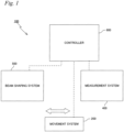
- FIG. 1 is a block diagram showing an entire structure of a shaping apparatus 100 according to the embodiment.
- Shaping apparatus 100 is a M3DP (Metal 3D printer) that employs DED (Directed Energy Deposition). Shaping apparatus 100 can be used to form a three-dimensional shaped object on a table 12 to be described later by rapid prototyping, as well as to perform additive manufacturing by three-dimensional shaping on a workpiece (e.g. an existing component).
- a workpiece e.g. an existing component
- the present embodiment will focus on describing the latter case where additive manufacturing is performed on the workpiece.
- Shaping apparatus 100 is equipped with; a movement system 200, a measurement system 400, and a beam shaping system 500, and a controller 600 including these systems that has overall control of shaping apparatus 100.
- measurement system 400, and beam shaping system 500 are placed spaced apart in a predetermined direction.
- measurement system 400, and beam shaping system 500 are to be placed spaced apart in an X-axis direction (refer to FIG. 2 ) to be described later on.
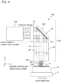
- FIG. 2 schematically shows a structure of movement system 200, along with that of measurement system 400.
- FIG. 3 shows movement system 200 on which a workpiece W is mounted in a perspective view.
- the lateral direction of the page surface in FIG. 2 will be described as a Y-axis direction
- a direction orthogonal to the page surface will be described as the X-axis direction
- a direction orthogonal to the X-axis and the Y-axis will be described as a Z-axis direction
- rotation (tilt) directions around the X-axis, the Y-axis, and the Z-axis will be described as ⁇ x, ⁇ y, and ⁇ z directions, respectively.
- Movement system 200 changes position and attitude of a target surface (in this case, a surface on workpiece W on which a target portion TA is set) TAS (for example, refer to FIGS. 4 and 9A ) for shaping. Specifically, by driving the workpiece having the target surface and the table to be described later on where the workpiece is mounted in directions of six degrees of freedom (6-DOF) (in each of the X-axis, the Y-axis, the Z-axis, the ⁇ x, the ⁇ y, and the ⁇ z directions), position in directions of 6-DOF of the target surface is changed.
- 6-DOF degrees of freedom
- position in directions of three degrees of freedom (3-DOF) in the ⁇ x, the ⁇ y, and the ⁇ z directions will be referred to collectively as "attitude”, and corresponding to this, the remaining directions of three degrees of freedom (3-DOF) in the X-axis, the Y-axis, and the Z-axis directions will be referred to collectively as "position”.
- movement system 200 is equipped with a Stewart platform type 6-DOF parallel link mechanism. Movement system 200 is not limited to a system that can drive the table in directions of 6-DOF.
- Movement system 200 (excluding a stator of a planar motor to be described later on) is placed on a base BS installed on a floor F so that its upper surface is almost parallel to an XY plane, as shown in FIG. 2 .
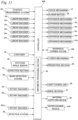
- Movement system 200 has a slider 10 having a regular hexagonal shape in a planar view that structures a base platform, table 12 that structures an end effector, six expandable rods (links) 14 1 to 14 6 for connecting slider 10 and table 12, and expansion mechanisms 16 1 to 16 6 (not shown in FIG. 3 , refer to FIG. 11 ) provided in each rod to make each rod expand and contract, as shown in FIG. 3 .
- Movement system 200 employs a structure so that the movement of table 12 can be controlled in 6-DOF within a three-dimensional space by separately adjusting the length of rods 14 1 to 14 6 with expansion mechanisms 16 1 to 16 6 .
- Movement system 200 is provided with features such as high accuracy, high rigidity, large supporting force, and easy inverse kinematic calculation, since the system is equipped with a Stewart platform type 6-DOF parallel link mechanism as a drive mechanism of table 12.
- position and attitude of the workpiece (table 12) are controlled with respect to beam shaping system 500, or more specifically, a beam from a beam irradiation section to be described later on so that a shaping object of a desired shape is formed of the workpiece at times such as additive manufacturing to the workpiece.
- the beam from the beam irradiation section may be movable or the beam and the workpiece (table) may both be movable.
- beam shaping system 500 has a complex structure, it is easier to move the workpiece instead.
- Table 12 here consists of a plate member having a shape of an equilateral triangle with each apex cut off. Workpiece W subject to additive manufacturing is mounted on the upper surface of table 12.
- a chuck mechanism 13 (not shown in FIG. 3 , refer to FIG. 11 ) for fixing workpiece W is provided at table 12.
- chuck mechanism 13 for example, a mechanical chuck or a vacuum chuck is used.
- the shape of table 12 is not limited to the shape shown in FIG. 3 , and may be any shape such as a rectangular plate shape or a disk shape.
- rods 14 1 to 14 6 are each connected to slider 10 and table 12 via universal joints 18 at both ends of the rods.
- Rods 14 1 and 14 2 are connected near one apex position of the triangle of table 12, and are placed so that slider 10 and these rods 14 1 and 14 2 structure a roughly triangular shape.
- rods 14 3 and 14 4 and rods 14 5 and 14 6 are connected, respectively, near each of the remaining apex positions of the triangle of table 12, and are placed so that slider 10 and rods 14 3 and 14 4 , and slider 10 and rods 14 5 and 14 6 each structure a roughly triangular shape.
- rods 14 1 to 14 6 each have a first shaft member 20 and a second shaft member 22 relatively movable in each axial direction as in rod 14 1 representatively shown in FIG. 3 , and one end (lower end) of the first shaft member 20 is attached to slider 10 via universal joint 18 and the other end (upper end) of the second shaft member 22 is attached to table 12 via a universal joint.
- a stepped columnar hollow portion is formed, and in the lower end side of the hollow portion, for example, a bellows type air cylinder is housed.
- a pneumatic circuit and an air pressure source are connected to this air cylinder.
- pneumatic pressure of compressed air supplied from the air pressure source via the pneumatic circuit, internal pressure of the air cylinder is controlled, which makes a piston that the air cylinder has move reciprocally in the axial direction.
- the air cylinder, in the returning process, is made to use gravitational force that acts on the piston when incorporated in the parallel link mechanism.
- an armature unit (not shown) is placed consisting of a plurality of armature coils placed lined in the axial direction.
- the second shaft member 22 is inserted into the hollow portion of the first shaft member 20.
- a small diameter section having a diameter smaller than other sections is formed, and a tubular mover yoke consisting of a magnetic member is provided around this small diameter section.
- a hollow columnar magnet body consisting of a plurality of permanent magnets of the same size, that is, a cylindrical magnet body is provided.
- the mover yoke and the magnet body structure a hollow columnar magnet unit.
- the armature unit and the magnet unit structure a shaft motor which is a type of electromagnetic linear motor.
- the magnet unit serving as the mover of the shaft motor is supported in a non-contact manner with respect to the armature unit serving as the stator, via an air pad provided on the inner circumferential surface of the first shaft member 20.
- rods 14 1 to 14 6 each have absolute linear encoders 24 1 to 24 6 provided for detecting the position of the second shaft member 22 in the axial direction with the first shaft member 20 as a reference, and the output of these linear encoders 24 1 to 24 6 is to be supplied to controller 600 (refer to FIG. 11 ) .
- the position of the second shaft member 22 in the axial direction detected by linear encoders 24 1 to 24 6 correspond to the respective length of rods 14 1 to 14 6 .
- controller 600 controls expansion mechanisms 16 1 to 16 6 (refer to FIG. 11 ). Details on the structure of the parallel link mechanism similar to movement system 200 of the embodiment are disclosed in, for example, U.S. Patent No. 6,940,582 , and controller 600 controls the position and the attitude of table 12 according to a method similar to the one disclosed in the above U.S. Patent using inverse kinematic calculation via expansion mechanisms 16 1 to 16 6 .
- controller 600 moves table 12 roughly and greatly by pneumatic control of the air cylinder as well as in a fine manner by the shaft motor. As a consequence, this allows the position in directions of 6-DOF (i.e., position and attitude) of table 12 to be controlled within a short time accurately.
- Rods 14 1 to 14 6 each have an air pad for supporting the magnet unit serving as the mover of the shaft motor in a noncontact manner with respect to the armature unit serving as the stator, therefore, friction which becomes a nonlinear component when controlling the expansion/contraction of the rods with the expansion mechanisms can be avoided, which allows more highly precise control of position and attitude of table 12.
- the shaft motor is used as the electromagnetic linear motor structuring expansion mechanisms 94 1 to 94 6 and the magnet unit using the cylindrical magnet is used in the mover side of the shaft motor, this generates magnetic flux (magnetic field) in all directions of radiation direction of the magnet and the magnetic flux in all directions can be made to contribute to generating the Lorentz force (drive force) by electromagnetic interaction, which allows thrust obviously larger when comparing to, for example, a normal linear motor or the like to be generated and allows easier downsizing when compared to a hydraulic cylinder or the like.
- low frequency vibration can be controlled by controlling air pressure of the air cylinder that structure each of the expansion mechanisms and high frequency vibration can be isolated by current control to the shaft motor.
- Movement system 200 is further equipped with a planar motor 26 (refer to FIG. 11 ) .
- a mover of planar motor 26 consisting of a magnet unit (or a coil unit) is provided, and corresponding to this, a stator of planar motor 26 consisting of a coil unit (or a magnet unit) is housed inside base BS.
- a plurality of air bearings air hydrostatic bearings
- slider 10 is supported by levitation via a predetermined clearance (gap or space) on the upper surface (guide surface) of base BS finished to have high degree of flatness.
- Movement system 200 by the electromagnetic force (Lorentz force) generated by the electromagnetic interaction between the stator and mover of planar motor 26, is driven within the XY plane in a noncontact manner with respect to the upper surface of base BS.
- movement system 200 can freely move table 12 between the placement positions of measurement system 400, beam shaping system 500, and a workpiece carrier system 300 (not shown in FIG. 1 , refer to FIG. 11 ) .
- movement system 200 may be equipped with a plurality of tables 12 on which workpiece W is mounted separately. For example, while processing using beam shaping system 500 is being performed on the workpiece held by one table of the plurality of tables, measurement using measurement system 400 may be performed on the workpiece held by another table.
- each table can be freely moved between the placement positions of measurement system 400, beam shaping system 500, and workpiece carrier system 300 (not shown in FIG. 1 , refer to FIG. 11 ).
- each slider 10 may be fixed on base BS.
- each table 12 can be moved in directions of 6-DOF, and the position in directions of 6-DOF of each table 12 can be controlled.
- Planar motor 26 is not limited to the motor that employs the air levitation method, and a planar motor employing a magnetic levitation method may also be used. In the latter case, the air bearings do not have to be provided in slider 10. As planar motor 26, both motors of a moving-magnet type and a moving-coil type can be used.
- Controller 600 can, by controlling at least one of the amount and the direction of electric current supplied to each coil of the coil unit structuring planar motor 26, drive slider 10 freely in the X and Y two-dimensional directions on base BS.
- movement system 200 is equipped with a position measurement system 28 (refer to FIG. 11 ) that measures position information of slider 10 in the X-axis direction and the Y-axis direction.
- a position measurement system 28 (refer to FIG. 11 ) that measures position information of slider 10 in the X-axis direction and the Y-axis direction.
- position measurement system 28 a two-dimensional absolute encoder can be used.
- a two-dimensional scale is provided that has a strip shaped absolute code of a predetermined width covering the whole length in the X-axis direction, and correspondingly on the bottom surface of slider 10, a light source such as a light emitting element is provided as well as an X head and a Y head that are structured by a one-dimensional light receiving element array arranged in the X-axis direction and a one-dimensional light receiving element array arranged in the Y-axis direction that respectively receive reflection light from the two-dimensional scale illuminated by the light beam emitted from the light source.
- the two-dimensional scale for example, a scale is used that has a plurality of square reflective portions (marks) arranged two-dimensionally at a predetermined period on a non-reflective base material (having a reflectance of 0%) along two directions orthogonal to each other (the X-axis direction and the Y-axis), and whose reflection characteristics (reflectance) of the reflective portions have gradation that follow predetermined rules.
- a structure similar to the two-dimensional absolute encoder disclosed in, for example, U.S. Patent Application Publication No. 2014/0070073 may be employed. According to the absolute two-dimensional encoder having a structure similar to that of U.S. Patent Application Publication No.
- the encoder allows measurement of two-dimensional position information with high precision which is around the same level as the conventional incremental encoder. Because the encoder is an absolute encoder, origin detection is not necessary unlike the incremental encoder. Measurement information of position measurement system 28 is sent to controller 600.
- position information within the three-dimensional space of at least a part of the target surface (e.g. the upper surface) of workpiece W mounted on table 12 is measured using measurement system 400, and then additive manufacturing (shaping) is performed on workpiece W after the measurement.
- controller 600 when measuring position information within the three-dimensional space of at least a part of the target surface on workpiece W, correlates the measurement results, measurement results of linear encoders 24 1 to 24 6 provided at rods 14 1 to 14 6 at the time of measurement, and measurement results of position measurement system 28, so that the position and attitude of the target surface of workpiece W mounted on table 12 can be correlated with a reference coordinate system (hereinafter called a table coordinate system) of shaping apparatus 100.
- a table coordinate system a reference coordinate system
- the position information within the three-dimensional space to be measured with measurement system 400 used for making position control in directions of 6-DOF with respect to the target value of target surface TAS on workpiece W according to open loop control on the position of table 12 in directions of 6-DOF is not limited to shape, and is sufficient if the information is three-dimensional position information of at least three points corresponding to the shape of the target surface.
- planar motor 26 as a drive device for driving slider 10 within the XY plane
- a linear motor may also be used instead of planar motor 26.
- the position measurement system that measures position information of slider 10 may be structured using the absolute linear encoder.
- the position measurement system that measures position information of slider 10 is not limited to the encoders and may also be structured by using an interferometer system.
- the mechanism for driving the table is structured using the planar motor which drives the slider within the XY plane and the Stewart platform type 6-DOF parallel link mechanism in which the slider structures the base platform
- the mechanism is not limited to this, and the mechanism for driving the table may also be structured by other types of parallel link mechanisms, or a mechanism other than the parallel link mechanism.
- a slider that moves in the XY plane and a Z-tilt drive mechanism that drives table 12 in the Z-axis direction and an inclination direction with respect to the XY plane on the slider may be employed.
- a mechanism can be given that supports table 12 at each apex position of the triangle from below, via joints such as, e.g. universal joints, and also has three actuators (such as voice coil motors) that can move each supporting point independently from one another in the Z-axis direction.
- joints such as, e.g. universal joints
- actuators such as voice coil motors
- the structure of the mechanism for driving the table in movement system 200 is not limited to these structures, and the mechanism only has to have the structure of being able to drive the table (movable member) on which the workpiece is mounted in directions of at least 5-DOF that are directions of 3-DOF within the XY plane, the Z-axis direction, and the inclination direction with respect to the XY plane, does not necessarily have to be equipped with a slider that moves within the XY plane.
- the movement system can be structured with a table and a robot that drives the table.
- reset can be performed easily when the measurement system for measuring the position of the table is structured using a combination of the absolute linear encoder, or a combination of the linear encoder and an absolute rotary encoder.
- a system that can drive table 12 in directions of at least 5-DOF, which are directions of 3-DOF within the XY plane, the Z-axis direction, and the inclination direction ( ⁇ x or ⁇ y) with respect to the XY plane may be employed.
- table 12 in itself may be supported by levitation (supported in a non-contact manner) via a predetermined clearance (gap or space) on the upper surface of a support member such as base BS, by air floatation or magnetic levitation.
- a support member such as base BS
- Measurement system 400 performs measurement of the three-dimensional position information of the workpiece, e.g. measurement of shape, to correlate the position and the attitude of the workpiece mounted on table 12 to the table coordinate system.
- Measurement system 400 is equipped with a laser noncontact type three-dimensional measuring machine 401, as shown in FIG. 2 .
- Three-dimensional measuring machine 401 is equipped with a frame 30 installed on base BS, a head section 32 attached to frame 30, a Z-axis guide 34 mounted on head section 32, a rotating mechanism 36 provided at the lower end of Z-axis guide 34, and a sensor section 38 connected to the lower end of rotating mechanism 36.
- Frame 30 consists of a horizontal member 40 extending in the Y-axis direction and a pair of column members 42 supporting horizontal member 40 from below at both ends of the Y-axis direction.
- Head section 32 is attached to horizontal member 40 of frame 30.
- Z-axis guide 34 is attached movable in the Z-axis direction to head section 32 and is driven in the Z-axis direction by a Z drive mechanism 44 (not shown in FIG. 2 , refer to FIG. 11 ). Position in the Z-axis direction (or displacement from a reference position) of Z-axis guide 34 is measured by a Z encoder 46 (not shown in FIG. 2 , refer to FIG. 11 ) .
- Rotating mechanism 36 rotationally drives sensor section 38 continuously (or in steps of a predetermined angle) around a rotation center axis parallel to the Z-axis within a predetermined angle range (e.g. within a range of 90 degrees ( ⁇ /2) or 180 degrees ( ⁇ )) with respect to head section 32 (Z-axis guide 34).
- a predetermined angle range e.g. within a range of 90 degrees ( ⁇ /2) or 180 degrees ( ⁇ )
- the rotation center axis of sensor section 38 according to rotating mechanism 36 coincides with a center axis of a line beam irradiated from an irradiation section to be described later on that structures sensor section 38.
- Rotation angle (or position of the sensor section in the ⁇ z direction) from a reference position of sensor section 38 according to rotating mechanism 36 is measured by a rotation angle sensor 48 (not shown in FIG. 2 , refer to FIG. 11 ) such as, for example, a rotary encoder.
- Sensor section 38 is structured mainly of an irradiation section 50 that irradiates a line beam for performing optical cutting on a test object (workpiece W in FIG. 2 ) mounted on table 12, and a detection section 52 that detects the surface of the test object in which an optical cutting surface (line) appears by being irradiated by the line beam.
- Sensor section 38 also has an arithmetic processing section 54 connected that acquires the shape of the test object on the basis of image data detected by detection section 52.
- Arithmetic processing section 54 in the embodiment is included in controller 600 (refer to FIG. 11 ) that has overall control over each part structuring shaping apparatus 100.
- Irradiation section 50 is structured of parts such as a cylindrical lens (not shown) and a slit plate having a thin strip-shaped cutout, and generates a fan-shaped line beam 50a by receiving illumination light from a light source.
- a light source LED, laser light source, SLD (super luminescent diode) or the like can be used.
- the light source can be formed at a low cost.
- a line beam with low aberration can be formed since the light source is a point light source, and since wavelength stability is superior and half bandwidth small, a filter of a small bandwidth can be used to cut stray light, which can reduce the influence of disturbance.
- Detection section 52 is used for imaging line beam 50a projected on the surface of the test object (workpiece W) from a direction different from the light irradiation direction of irradiation section 50.
- Detection section 52 is structured with parts (not shown) such as an imaging lens and a CCD, and as it is described later on, images the test object (workpiece W) each time table 12 is moved and line beam 50a is scanned at a predetermined interval.
- Positions of irradiation section 50 and detection section 52 are decided so that an incident direction to detection section 52 of line beam 50a on the surface of the test object (workpiece W) and a light irradiation direction of irradiation section 50 form a predetermined angle ⁇ .
- the above predetermined angle ⁇ is set to, e.g. 45 degrees.
- the image data of the test object (workpiece W) imaged by detection section 52 is sent to arithmetic processing section 54 where a predetermined arithmetic processing is performed to calculate the surface height of the test object (workpiece W) so that a three-dimensional shape (surface shape) of the test object (workpiece W) can be acquired.
- Arithmetic processing section 54 in the image of the test object (workpiece W), calculates the height of the test object (workpiece W) surface from a reference plane using a principle of triangulation for each pixel in the longitudinal direction in which the optical cutting surface (line) (line beam 50a) extends and performs arithmetic processing to acquire the three-dimensional shape of the test object (workpiece W), on the basis of position information of optical cutting surface (line) by line beam 50a deformed according to the unevenness of the test object (workpiece W).
- controller 600 moves table 12 in a direction substantially orthogonal to the longitudinal direction of line beam 50a projected on the test object (workpiece W) so that line beam 50a scans the surface of test object (workpiece W). Controller 600 detects rotation angle of sensor section 38 with rotation angle sensor 48, and moves table 12 in the direction substantially orthogonal to the longitudinal direction of line beam 50a based on the detection results.
- the position and the attitude of table 12 are constantly set to a predetermined reference state at the point when table 12 enters an area under sensor section 38 of measurement system 400 holding workpiece W.
- position (X, Y) within the XY plane of table 12 coincides with the X and the Y positions of slider 10 measured with position measurement system 28.
- controller 600 controls the position in directions of 6-DOF of table 12 by controlling planar motor 26 based on the measurement information of position measurement system 28 and by controlling expansion mechanisms 16 1 to 16 6 based on the measurement values of linear encoders 24 1 to 24 6 .
- line beam 50a irradiated on the test obj ect (workpiece W) from irradiation section 50 of sensor section 38 is preferably arranged in a direction orthogonal to a relative movement direction between sensor section 38 and table 12 (test object (workpiece W)).
- line beam 50a is preferably arranged along the X-axis direction.
- Rotating mechanism 36 is provided so that the direction of line beam 50a and the relative movement direction described above can be orthogonal constantly.
- Three-dimensional measuring machine 401 described above is structured similarly to the shape measurement apparatus disclosed in, for example, U.S. Patent Application Publication No. 2012/0105867 .
- scanning of the line beam with respect to the test object in directions parallel to the X, Y planes is performed by movement of the sensor section in the apparatus described in U.S. Patent Application Publication No. 2012/0105867
- the embodiment differs on the point that the scanning is performed by moving table 12.
- scanning of the line beam with respect to the test object in a direction parallel to the Z-axis may be performed by driving either Z-axis guide 34 or table 12.
- a linear projection pattern consisting of a line beam is projected on the surface of the test object, and each time the linear projection pattern is scanned with respect to the whole surface of the test object surface, the linear projection pattern projected on the test object is imaged from an angle different from the projection direction. Then, from the captured image of the test object surface that was imaged, the height of the test object surface from the reference plane is calculated using the principle of triangulation for each pixel in the longitudinal direction of the linear projection pattern, and the three-dimensional shape of the test object surface is acquired.
- a device having a structure similar to an optical probe disclosed in, for example, U.S. Patent No. 7, 009, 717 can also be used.
- This optical probe is structured by two or more optical groups, and includes two or more visual field directions and two or more projection directions.
- One optical group includes one or more visual field direction and one or more projection direction, and at least one visual field direction and at least one projection direction differ between the optical groups, and data acquired from the visual field direction is generated only from a pattern projected from the projection direction in the same optical group.
- Measurement system 400 may be equipped with a mark detection system 56 (refer to FIG. 11 ) for optically detecting an alignment mark instead of the three-dimensional measuring machine 401,above, or in addition to the three-dimensional measuring machine described above.
- Mark detection system 56 can detect an alignment mark formed, for example, on the workpiece.
- Controller 600 by accurately detecting each center position (three-dimensional coordinate) of at least three alignment marks using mark detection system 56, calculates the position and attitude of the workpiece (or table 12).
- mark detection system 56 can be structured including, e.g. a stereo camera.
- a structure may also be employed in which mark detection system 56 optically detects alignment marks arranged beforehand at a minimum of three places on table 12.
- controller 600 scans the surface (target surface) of workpiece W and acquires the surface shape data, using the three-dimensional measuring machine 401 in the manner described above. Then, controller 600 performs least-square processing and performs correlation of the three-dimensional position and attitude of the target surface on the workpiece to the table coordinate system using the surface shape data.
- control of the position (that is, position and attitude) of workpiece W in directions of 6-DOF including the time of additive manufacturing by three-dimensional shaping can all be performed by an open-loop control of table 12 according to the table coordinate system, after the three-dimensional position and attitude have been correlated to the table coordinate system.
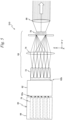
- FIG. 4 shows beam shaping system 500, along with table 12 on which workpiece W is mounted.
- beam shaping system 500 includes a light source system 510, and is equipped with a beam irradiation section 520 that emits a beam, a material processing section 530 that supplies a powdery shaping material, and a water shower nozzle 540 (not shown in FIG. 4 , refer to FIG.11 ). Note that beam shaping system 500 does not have to be equipped with water shower nozzle 540.
- Light source system 510 is equipped with a light source unit 60, a light guide fiber 62 connected to light source unit 60, and a double fly-eye optical system 64 and a condenser lens system 66 placed on the exit side of light guide fiber 62.
- Light source unit 60 has a housing 68, and a plurality of laser units 70 which are housed inside housing 68 and are arranged parallel to one another in the shape of a matrix.
- laser unit 70 a unit that serves as a light source can be used such as various types of lasers that perform pulse oscillation or continuous wave oscillating operation, an Nd:YAG laser, a fiber laser, or a GaN-based semiconductor laser.
- Light guide fiber 62 is a fiber bundle structured by randomly bundling many optical fiber strands that has a plurality of incident ports 62a connected individually to the light-emitting end of the plurality of laser units 70 and a light-emitting section 62b that has more light-emitting ports than the number of incident ports 62a.
- Light guide fiber 62 receives a plurality of laser beams (hereinafter appropriately shortened to as a "beam”)) emitted from each of the plurality of laser units 70 via each incident port 62a and distributes the beam to the plurality of light-emitting ports so that at least a part of each laser beam is emitted from a common light-emitting port.
- beam laser beams
- light guide fiber 62 mixes and emits the beams emitted from each of the plurality of laser units 70. This allows the total output to be increased according to the number of laser unit 70s when compared to the case when a single laser unit is used. However, the plurality of laser units do not have to be used in the case the output acquired is enough using a single laser unit.
- Light-emitting section 62b here has a sectional shape similar to a whole shape of an incident end of a first fly-eye lens system that structures an incident end of double fly-eye optical system 64 which will be described next, and the light-emitting ports are provided in an approximately even arrangement within the section. Therefore, light guide fiber 62 also serves as a shaping optical system that shapes the beam mixed in the manner described above so that the beam is shaped similar to the whole shape of the incident end of the first fly-eye lens system.
- Double fly-eye optical system 64 is a system for making a uniform cross-sectional illuminance distribution (sectional intensity distribution) of the beam (illumination light), and is structured with a first fly-eye lens system 72, a lens system 74, and a second fly-eye lens system 76 arranged sequentially on a beam path (optical path) of the laser beam behind light guide fiber 62. Note that a diaphragm is provided in the periphery of the second fly-eye lens system 76.
- an incidence plane of the first fly-eye lens system 72 and an incidence plane of the second fly-eye lens system 76 are set optically conjugate to each other.
- a focal plane (a surface light source to be described later is formed here) on the exit side of the first fly-eye lens system 72, a focal plane (a surface light source to be described later is formed here) on the exit side of the second fly-eye lens system 76, and a pupil plane (entrance pupil) PP of a condensing optical system 82 (to be described later on) are set optically conjugate to one another.
- a pupil plane (entrance pupil) PP of a condensing optical system 82 coincides with a focal plane on the front side (refer to FIGS. such as, for example, 4, 6 and 7).
- the beam mixed by light guide fiber 62 is incident on the first fly-eye lens system 72 of double fly-eye optical system 64.
- a surface light source i.e. secondary light source consisting of many light source images (point light sources)
- the laser beams from each of the many point light sources are incident on the second fly-eye lens system 76 via lens system 74.
- a surface light source (a tertiary light source) in which many fine light source images distributed in a uniform manner within an area of a predetermined shape are formed on a focal plane on the exit side of the second fly-eye lens system 76.
- Condenser lens system 66 emits the laser beam emitted from the tertiary light source described above as a beam that has uniform illuminance distribution.
- the beam emitted from condenser lens system 66 can be regarded as a parallel beam.
- Light source 510 of the embodiment is equipped with an illuminance uniformizing optical system that is equipped with light guide fiber 62, double fly-eye optical system 64, and condenser lens system 66, and using this illuminance uniformizing optical system, mixes the beams emitted from each of the plurality of laser units 70 and generates a parallel beam having a cross-section with uniform illuminance distribution.
- the illuminance uniformizing optical system is not limited to the structure described above.
- the illuminance uniformizing optical system may be structured using a rod integrator or a collimator lens system.
- Light source unit 60 of light source system 510 is connected to controller 600, and controller 600 individually controls the on/off of the plurality of laser units 70 structuring light source unit 60. With this control, the amount of light of the laser beam (laser output) irradiated (on the target surface) on workpiece W from beam irradiation section 520 is adjusted.
- shaping apparatus 100 does not have to be equipped with light source unit 60, or light source unit and the illuminance uniformizing optical system.
- a parallel beam having a desired light amount (energy) and desired illuminance uniformity may be supplied to shaping apparatus 100 from an external device.
- Beam irradiation section 520 other than light source system 510, has a beam section intensity conversion optical system 78, a mirror array 80 which is a type of spatial light modulator (SLM: Spatial Light Modulator), and a condensing optical system 82 which condenses the light from mirror array 80 that are sequentially arranged on the optical path of the parallel beam from light source system 510 (condenser lens system 66), as shown in FIG. 4 .
- the spatial light modulator here is a general term for an element that spatially modulates the amplitude (intensity), phase, or state of polarization of light advancing in a predetermined direction.
- Beam section intensity conversion optical system 78 performs conversion of the intensity distribution of the cross sectional surface of the parallel beam from light source system 510 (condenser lens system 66).
- beam section intensity conversion optical system 78 converts the parallel beam from light source system 510 into a parallel beam having a donut shape (annular shape) with the intensity of an area including the center of the cross sectional surface being substantially zero.
- Beam section intensity conversion optical system 78 in the embodiment, is structured, for example, with a convex conically shaped reflection mirror and a concave conically shaped reflection mirror that are sequentially placed on the optical path of the parallel beam from light source system 510.
- the convex conically shaped reflection mirror has a conically shaped reflection surface formed on its outer peripheral surface on the light source system 510 side, and the concave conically shaped reflection mirror, consisting of an annular-shaped member having an inner diameter larger than the outer diameter of the convex conically shaped reflection mirror, has a reflection surface facing the reflection surface of the convex conically shaped reflection mirror formed on its inner peripheral surface.
- the reflection surface of the convex conically shaped reflection mirror and the reflection surface of the concave conically shaped reflection mirror are parallel.
- the parallel beam from light source system 510 is reflected radially by the reflection surface of the convex conically shaped reflection mirror, and by this reflection beam being reflected by the reflection surface of the concave conically shaped reflection mirror, the beam is converted into the annular shaped parallel beam.
- the parallel beam that passes through beam section intensity conversion optical system 78 is irradiated on the workpiece, via mirror array 80 and condensing optical system 82 in the manner to be described later on.
- beam section intensity conversion optical system 78 By converting the intensity distribution of the cross sectional surface of the parallel beam from light source system 510 using beam section intensity conversion optical system 78, it becomes possible to change intensity distribution of the beam incident on pupil plane (entrance pupil) of condensing optical system 82 from mirror array 80.
- pupil plane entrance pupil
- the intensity distribution of the cross sectional surface of the parallel beam from light source system 510 using beam section intensity conversion optical system 78 it becomes possible to substantially change intensity distribution in the exit plane of condensing optical system 82 of the beam emitted from condensing optical system 82.
- beam section intensity conversion optical system 78 is not limited to the combination of the convex conically shaped reflection mirror and the concave conically shaped reflection mirror, and may be structured using a combination of a diffractive optical element, an afocal lens, and a conical axicon system as is disclosed in, for example, U.S. Patent Application Publication No. 2008/0030852 .
- Beam section intensity conversion optical system 78 is sufficient if it performs conversion of the intensity distribution of the cross sectional surface of the beam, and various structures can be considered.
- beam section intensity conversion optical system 78 it is possible to make the parallel beam from light source 510 such that the intensity in the area including the center of the cross sectional surface (optical axis of condensing optical system 82) is not nearly zero, but smaller than the intensity on the outer side of the area.
- Mirror array 80 can substantially form a large reflection surface parallel to the reference surface by adjusting tilt of numerous mirror elements 81 p,q with respect to the reference surface.
- Each mirror element 81 p,q of mirror array 80 is structured rotatable around a rotation axis parallel to one diagonal line of mirror element 81 p,q , and a tilt angle of its reflection surface with respect to the reference surface can be set to an arbitrary angle within a predetermined angle range.
- the angle of the reflection surface of each mirror element is measured using a sensor that detects a rotation angle of the rotation axis, e.g. a rotary encoder 83 p,q (not shown in FIG. 4 , refer to FIG. 11 ).
- Drive section 87 for example, includes an electromagnet or a voice coil motor serving as an actuator, and the individual mirror elements 81 p,q are driven by the actuator and operate at an extremely high response.
- each of the mirror elements 81 p,q illuminated by the annular shape parallel beam from light source system 510 emits a reflection beam (parallel beam) according to the tilt angle of the reflection surface and makes the beam enter condensing optical system 82 (refer to FIG. 6 ).
- the parallel beam does not necessarily have to be an annular shape, and the cross sectional surface shape (cross sectional surface intensity distribution) of the parallel beam entering mirror array 80 may be made different from the annular shape, or beam section intensity conversion optical system 78 may not have to be provided.
- Condensing optical system 82 is a high numerical aperture (N.A.) and low aberration optical system having a numerical aperture of, e.g. 0.5 or more, or preferably 0.6 or more. Because condensing optical system 82 has a large diameter, low aberration, and high N.A., the plurality of parallel beams from mirror array 80 can be condensed on a rear focal plane. Although details will be described later on, beam irradiation section 520 can condense the beam emitted from condensing optical system 82 into, e.g. a spot shape or a slit shape. In addition, because condensing optical system 82 is structured using one or a plurality of large diameter lenses ( FIG.
- the area of incident light can be enlarged, which allows more light energy to be taken in when compared to the case of using a condensing optical system with a small N.A.. Consequently, the beam condensed using condensing optical system 82 according to the embodiment is extremely sharp and will have high energy density, which is connected directly with improving the processing accuracy of additive manufacturing by shaping.
- table 12 may be moved in at least one of the X-axis direction, the Z-axis direction, the ⁇ x direction, the ⁇ y direction, and the ⁇ z direction, during the movement of table 12 in the Y-axis direction on shaping.
- powdery shaping material (metal material) supplied from material processing section 530 is melted by the energy of the laser beam. Consequently as it is previously described, if the total amount of energy that condensing optical system 82 takes in becomes larger, the amount of energy of the beam emitted from condensing optical system 82 becomes larger, and this increases the amount of metal that can be melted in a unit time. If the amount of the shaping material supplied and the speed of table 12 are increased accordingly, this increases throughput of shaping processing by beam shaping system 500.
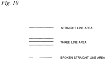
- an irradiation area of a slit shaped beam (hereinafter called a straight line area (refer to reference code LS in FIG. 9B )) can be formed instead of an irradiation area of a spot shaped beam on a predetermined plane (hereinafter called shaping surface) MP (refer to, e.g.
- FIGS 4 and 9A where target surface TAS of shaping is to be aligned, and shaping (machining processing) can be performed while relatively scanning workpiece W with respect to a beam forming straight line area LS (hereinafter called a straight line beam) in a direction perpendicular to the longitudinal direction of the beam.
- a beam forming straight line area LS hereinafter called a straight line beam
- shaping surface MP described above is a rear focal plane of condensing optical system 82 in the embodiment as it will be described later on, the shaping surface may be a surface near the rear focal plane.
- shaping surface MP is perpendicular to an optical axis AX at the exit side of condensing optical system 82, the surface does not have to be perpendicular.
- a method of setting or changing the intensity distribution of the beam on shaping surface MP e.g. a method of forming the straight line area as in the description above
- a method can be employed in which an incidence angle distribution of the plurality of parallel beams incident on condensing optical system 82 is controlled.
- the focal position at the rear focal plane is determined by the incidence angle of parallel beam LB (e.g. refer to FIGS. 4 and 6 ) on pupil plane (entrance pupil) PP.
- the incidence angle here is decided from, a.
- an angle ⁇ (0 ⁇ 90 degrees ( ⁇ /2)) which is an angle that the parallel beam incident on pupil plane PP of condensing optical system 82 forms with respect to an axis parallel to optical axis AX of condensing optical system 82, and b. a reference axis (e.g.
- the beam that is incident on pupil plane PP of condensing optical system 82 perpendicularly (parallel to the optical axis) condenses on optical axis AX
- the beam that is slightly tilted with respect to condensing optical system 82 (with respect to optical axis AX) condenses at a position slightly shifted from the position on optical axis AX.
- At least one of position, number, size and shape of the irradiation area in shaping surface MP can be arbitrarily changed. Consequently, it is naturally easy to form areas such as, e.g. a straight line area, a three line area, or a broken straight line area (refer to FIG. 10 ), and is also easy to form a spot shaped irradiation area.
- the incidence angle (incident direction) is described here using angle ⁇ and angle ⁇ , various ways may be considered of expressing the incidence angle (incident direction), and it goes without saying that the incidence angle (incident direction) of the parallel beam incident on pupil plane PP is not limited to the control using angle ⁇ and angle ⁇ as parameters.
- condensing optical system 82 of the embodiment since the structure is employed so that pupil plane (entrance pupil) PP coincides with the front focal plane, the condensing position of the plurality of parallel beams LB can be controlled accurately in a simple manner by changing the incidence angle of the plurality of parallel beams LB using mirror array 80, however, the structure of the pupil plane (entrance pupil) PP and the front focal plane coinciding does not necessarily have to be employed.
- the position of the irradiation area can also be changed by controlling the incidence angle of one parallel beam incident on the pupil plane of condensing optical system 82 using a solid mirror of a desired shape.
- the area of the target surface on which the target portion of shaping is not always set constantly on a flat surface. That is, relative scanning of the straight line beam is not always possible.
- the border may be tilted, narrow or curved, making it difficult to apply relative scanning of the straight line beam. For instance, since it is difficult to paint out such an area with a wide brush, a thin brush corresponding to the area or a thin pencil will be necessary, that is to say, the brushes and the thin pencil are to be used to suit their use freely real time and continuously.
- mirror array 80 is employed, and controller 600 makes each mirror element 81 p,q operate at an extremely high response so that the incidence angle of the plurality of parallel beams LB entering pupil plane PP of condensing optical system 82 can be controlled respectively.
- controller 600 can change the intensity distribution of the beam on shaping surface MP, such as, for example, at least one of shape, size, and number of the irradiation area of the beam, during relative movement of the beam and target surface TAS (a surface on which target portion TA of shaping is set, and in the embodiment, a surface on workpiece W) .
- controller 600 can continuously or intermittently change the intensity distribution of the beam on shaping surface MP.
- Controller 600 can also change the intensity distribution of the beam on shaping surface MP according to the relative position of the beam and target surface TAS. Controller 600 can also change the intensity distribution of the beam on shaping surface MP according to a required shaping accuracy and throughput.
- controller 600 detects the state of each mirror element (in this case, tilt angle of the reflection surface) using rotary encoder 83 p,q previously described, and by this detection, monitors the state of each mirror element real time so that the tilt angle of the reflection surface of each mirror element of mirror array 80 can be accurately controlled.
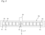
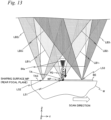
- Material processing section 530 has a nozzle unit 84 which has a nozzle member (hereinafter shortly described as a nozzle) 84a provided below the exit plane of condensing optical system 82, a material supplying device 86 connected to nozzle unit 84 via a piping 90a, a plurality of, e.g. two, powder cartridges 88A and 88B each connected to material supplying device 86 via piping.
- FIG. 7 shows a portion below condensing optical system 82 shown in FIG. 4 , when viewed from the -Y direction.
- Nozzle unit 84 extends in the X-axis direction below condensing optical system 82, and is equipped with a nozzle 84a that has at least one supplying port for supplying powdered shaping material, and a pair of support members 84b and 84c that support both ends in the longitudinal direction of nozzle 84a and also have each upper end connected to the housing of condensing optical system 82.
- a nozzle 84a that has at least one supplying port for supplying powdered shaping material
- support members 84b and 84c that support both ends in the longitudinal direction of nozzle 84a and also have each upper end connected to the housing of condensing optical system 82.
- To one of the support members, 84b one end (the lower end) of material supplying device 86 is connected via piping 90a, and support member 84b has a supply path formed inside that communicates piping 90a with nozzle 84a.
- nozzle 84a is placed directly below the optical axis of condensing optical system 82, and in its lower surface (bottom surface), has a plurality of supply ports provided that will be described later on. Note that nozzle 84a does not necessarily have to be placed on the optical axis of condensing optical system 82, and may be placed at a position slightly shifted from the optical axis to one side of the Y-axis direction.
- powder cartridges 88A and 88B are connected to material supplying device 86 via piping 90b and 90c, respectively.
- powder cartridges 88A powder of a first shaping material (e.g. titanium) is stored.
- powder of a second shaping material e.g. stainless steel
- shaping apparatus 100 is equipped with two powder cartridges for supplying two types of shaping material to material supplying device 86, the number of powder cartridges that shaping apparatus 100 is equipped with may be one.
- material supplying device 86 is made to have a function of switching between piping 90b and 90c, as well as a function of performing suction of the powder from either powder cartridge 88A or 88B by using vacuum.
- Material supplying device 86 is connected to controller 600 (refer to FIG. 11 ).
- Material supplying device 86 is connected to controller 600 (refer to FIG. 11 ).
- controller 600 performs switching between piping 90b and 90c using material supplying device 86, selectively chooses between the powder of the first shaping material (e.g. titanium) from powder cartridge 88A and the powder of the second shaping material (e.g. stainless steel) from powder cartridge 88B, and supplies the powder of one of the shaping materials to nozzle 84a from material supplying device 86 via piping 90a.
- material supplying device 86 a structure may be employed in which the powder of the first shaping material from powder cartridge 88A and the powder of the second shaping material from powder cartridge 88B are supplied simultaneously to material supplying device 86 when necessary, and the mixture of the two shaping materials can be supplied to nozzle 84a via piping 90a.
- a nozzle connectable to powder cartridge 88A and another nozzle connectable to powder cartridge 88B may be provided below condensing optical system 82 so as to supply the powder at the time of shaping from either one of the nozzles, or from both of the nozzles.
- the number of supply ports is not limited, as long as the supply ports are arranged along almost the entire length in the longitudinal direction of nozzle 84a.
- the supply port may be one slit shaped opening that is arranged along almost the entire length in the longitudinal direction of nozzle 84a.
- Each open/close member 93 i is driven and controlled by controller 600, via an actuator not shown.
- Controller 600 performs open/close control of each of the plurality of supply ports, e.g. N supply ports 91 i , using each open/close member 93 i according to the intensity distribution of the beam on the shaping surface, such as for example, setting (or change) of the shape, the size, and the arrangement of the irradiation area of the beam formed on the shaping surface. This allows the supply operation of the shaping material by material processing section 530 to be controlled.
- controller 600 selects at least one supply port of the plurality of supply ports 91 i , and only open/close member 93 i that closes the selected at least one supply port operates under the open control, or for example, is driven in the -Y direction. Consequently, in the embodiment, the shaping material can be supplied using only a part of the plurality of, or N supply ports 91 i .
- controller 600 can adjust the supply amount per unit time of the shaping material from supply port 91 i opened/closed by the arbitrary open/close member 93 i previously described.
- Controller 600 determines the supply amount per unit time of the shaping material from the arbitrary supply port 91 i according to the intensity distribution of the beam on the shaping surface, such as setting (or change) of the shape, the size, and the arrangement of the irradiation area of the beam formed on the shaping surface.
- Controller 600 determines the supply amount per unit time from each supply port 91 i based on, for example, the width of the scan direction of the straight line area previously described.
- At least one supply port that supplies the powdered shaping material may be movable.
- a structure may be employed in which one slit shaped supply port extending in the X-axis direction is formed on the lower surface of nozzle 84a and nozzle 84a is made movable, for example, in at least either the X-axis direction or the Y-axis direction with respect to the pair of support members 84b and 84c, and controller 600 may move nozzle 84a that has the supply port formed on its lower surface according to intensity distribution change of the beam on the shaping surface, that is, change in shape, size, and position of the irradiation area of the beam.
- nozzle 84a may also be movable in the Z-axis direction.
- a structure may be employed in which one supply port and another supply port of the plurality of supply ports are relatively movable.
- the position in the Y-axis direction may differ between the one supply port described above and the another supply port described above.
- the position in the Z-axis direction may differ between the one supply port described above and the another supply port described above.
- moving of at least one supply port may be performed not only with setting or changing the intensity distribution of the beam, but may be moved also for other purposes.
- shaping material PD will be supplied to the straight line area LS (irradiation area of the straight line beam) previously described directly below optical axis AX of condensing optical system 82.
- the supply of shaping material PD from nozzle 84a can be performed by using self-weight of shaping material PD or by blowout to which a slight blowout pressure is applied.
- the shaping material can be supplied perpendicularly at close range to the workpiece as in the embodiment when securing processing accuracy on shaping.
- a gas supply port may be provided at nozzle 84a.
- the gas flow of the gas supplied from the gas supply port may be used to guide the shaping material supplied or may be used for other purposes such as to contribute to shaping.
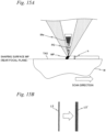
- the straight line beam for example, is formed only by the light that passes through the area near the periphery of the same condensing optical system 82. Therefore, a beam spot (laser spot) with high quality can be formed when compared to the case when a beam spot light that passes separate optical systems are condensed on the same area.
- a limit can be set to the beam irradiated on nozzle 84a provided in the center below the exit plane (lower end surface) of condensing optical system 82.
- the embodiment it becomes possible to use all the reflection beams from mirror array 80 to form the spot, and parts such as a light shielding member to limit the beam irradiating on nozzle 84a will not necessarily have to be arranged at the part corresponding to nozzle 84a on the incident surface side of condensing optical system 82.
- the annular shape parallel beam is used to illuminate mirror array 80.
- the optical member positioned at the exit end of condensing optical system 82 only has to be a member that at least can form an optical surface at an area distanced from an optical axis of a surface on the exit side and condense a beam on a shaping surface (rear focal plane) via the optical surface. Consequently, this optical member may be a member having at least one of the exit surface and the incidence plane perpendicular to the optical axis of condensing optical system in the area including the optical axis, or having a hole formed in the area including the optical axis.
- the optical member positioned at the exit end of condensing optical system 82 may be structured arranging a donut shaped condensing lens with a hole in the center part area including the optical axis.
- a limit member 85 indicated by a double dotted line in FIG. 7 may be provided at the incidence plane side (e.g. pupil plane PP) of condensing optical system 82.
- Limit member 85 limits the beam from condensing optical system 82 when entering nozzle 84a.
- a light shielding member may be used, parts such as a light attenuation filter may also be used.
- the parallel beam incident on condensing optical system 82 may be a parallel beam having a circular sectional shape, or may be an annular shape beam. In the latter case, because the beam is not irradiated on limit member 85, it becomes possible to use the reflection beam from mirror array 80 exclusively for forming the spot.
- the beam incident on nozzle 84a from condensing optical system 82 does not necessarily have to be shielded completely, to prevent the beam from condensing optical system 82 being incident on nozzle 84a, the beam may be made incident only from separate periphery end part areas (e.g. two circular arc areas) at both sides of the optical axis in the Y-axis direction at the exit plane of a terminal end lens of condensing optical system 82.
- periphery end part areas e.g. two circular arc areas
- Water shower nozzle 540 (refer to FIG. 11 ) is used on the so-called quenching.
- Water shower nozzle 540 has a supply port that supplies a cooling liquid (cooling water) and spouts the cooling liquid at a cooling target.
- Water shower nozzle 540 is connected to controller 600 (refer to FIG. 11 ).
- Controller 600 controls light source unit 60 on quenching so that thermal energy of the beam from beam irradiation section 520 is adjusted to an appropriate value for quenching. Then, after irradiating the beam on the surface of the workpiece to increase the temperature to a high degree, controller 600 can perform quenching by spouting the cooling liquid at the high temperature part to rapidly cool the part, via water shower nozzle 540.
- FIG.9A is an enlarged view of FIG. 4 and circle A of FIG. 4
- the beam (illustrated as beams LB1 1 and LB1 2 for the sake of convenience in FIG. 9A ) that passes though the vicinity of the periphery end part of condensing optical system 82 and though the optical path of nozzle 84a on the +Y side and -Y side (the front and the rear of the scan direction of workpiece W (table 12)) is condensed directly below nozzle 84a, and straight line area LS with a longitudinal direction in the X-axis direction (orthogonal direction of the page surface in FIG.
- beams LB1 1 and LB1 2 shown in FIG. 9A may be separate parallel beams that are incident on pupil plane PP of condensing optical system 82 at different incidence angles each reflected by different mirror elements 81 p,q of mirror array 80, or may be the same parallel beam, such as for example, a part of a parallel beam having an annular sectional shape.
- laser output (energy amount of the laser beam) of at least one of the plurality of laser units 70 may be adjusted according to the width in the X-axis direction or the Y-axis direction or both of the straight line beam, or the number of parallel beams LB incident on condensing optical system 82 from mirror array 80 may be changed.
- the throughput slightly decreases when compared to the adjustment method described above, the adjustment is simple.
- FIG. 11 shows a block diagram indicating an input/output relation of controller 600 that mainly structures a control system of shaping apparatus 100.
- Controller 600 includes a workstation (or a microcomputer) and the like and has overall control over constituent parts of shaping apparatus 100.
- shaping apparatus100 The basic function of shaping apparatus100 according to the embodiment structured in the manner described above is to add a desired shape by three-dimensional shaping to an existing component (workpiece) .
- the workpiece is supplied to shaping apparatus 100 and then is carried out from shaping apparatus 100 after a desired shape is accurately added.
- the actual shaping data of the shape that has been added is sent to an external device, such as a host device.
- the series of operations performed in shaping apparatus 100 is roughly in the manner described below.
- controller 600 moves table 12 on which workpiece W is loaded to an area below measurement system 400.
- the movement of table 12 is performed by controller 600 controlling planar motor 26 based on the measurement information of position measurement system 28 so that slider 10 is driven in the X-axis direction (and the Y-axis direction) on base BS.
- Table 12 maintains the reference state previously described also during this movement.
- controller 600 performs measurement of position information within a three-dimensional space (shape information in the embodiment) which is at least a part of target surface TAS on workpiece W that is on table 12 in a reference state, using measurement system 400.
- position information within a three-dimensional space (shape information in the embodiment) which is at least a part of target surface TAS on workpiece W that is on table 12 in a reference state
- measurement system 400 uses measurement system 400 to control the position in directions of 6-DOF of target surface TAS on workpiece W that is on the table coordinate system (reference coordinate system) according to open loop control, based on the measurement results.
- controller 600 moves table 12, on which workpiece W having completed measurement of shape information of at least a part of target surface TAS is mounted, to an area below beam shaping system 500.
- additive manufacturing according to three-dimensional shaping is performed in which the shape corresponding to 3D data is added to the workpiece on table 12. This additive manufacturing is performed as follows.
- controller 600 converts the three-dimensional CAD data of the shape to be added by additive manufacturing (shape in which the shape of the workpiece subject to additive manufacturing is removed from the shape of the object made after additive manufacturing has been applied) serving as three-dimensional shaping data to, e.g. STL (Stereo Lithography) data, and then furthermore generates data for each layer sliced in the Z-axis direction from this three-dimensional STL data.
- additive manufacturing shape in which the shape of the workpiece subject to additive manufacturing is removed from the shape of the object made after additive manufacturing has been applied
- STL Stepo Lithography
- controller 600 controls movement system 200 and beam shaping system 500 so that additive manufacturing is performed on each layer of the workpiece based on the data of each layer, and repeatedly performs formation of the straight line area and formation of the linear (slit shaped) molten pool by supplying shaping material from nozzle 84a to the straight line beam while scanning table 12 in the scan direction, for each layer.
- position and attitude control of the target surface on the workpiece at the time of additive manufacturing is performed taking into consideration the target surface measured earlier.
- shaping accompanied with scanning operation of table 12 is to be performed presupposing that target surface (e.g. upper surface) TAS on which target portion TA of additive manufacturing of workpiece W is set is a plane set to a surface perpendicular to the optical axis of condensing optical system 82 by adjusting the tilt of table 12.
- target surface where the target portion of additive manufacturing of the workpiece is set is not always a plane where the straight line beam can be used.
- shaping apparatus 100 according to the embodiment is equipped with movement system 200 that can set arbitrarily the position of table 12 on which the workpiece is loaded in directions of 6-DOF.
- controller 600 while controlling measurement system 200 and beam irradiation section 520 of beam shaping system 500 based on the three-dimensional shape of the workpiece measured using measurement system 400 and adjusting the width in the X-axis direction of the beam irradiation area on shaping surface MP so that the target surface (e.g. upper surface) of workpiece W positioned on shaping surface MP can be regarded flat enough so that additive manufacturing can be performed in the irradiation area of the beam in shaping surface MP, performs the open/close operation of each supply port 91i via each open/close member 93i of nozzle 84a and supplies the shaping material from the required supply ports to the beam irradiated on the irradiation area.
- This allows the shaping to be applied at necessary parts even when the upper surface (target surface) of the workpiece is not flat.
- additive manufacturing may be performed with a beam whose width in the X-axis direction of the irradiation area in the shaping surface is narrow, and after forming a plane having a relatively large area, additive manufacturing (bead formation) may be performed on the plane using a straight line beam whose width in the X-axis direction of the irradiation area in the shaping surface is widened.
- additive manufacturing (bead formation) to fill the recess part may be performed with a beam whose width in the X-axis direction of the irradiation area in the shaping surface is narrow, and after forming a plane, additive manufacturing (bead formation) may be performed on the plane using a straight line beam whose width in the X-axis direction of the irradiation area in shaping surface MP is widened.
- the powdered shaping material is supplied from one or the plurality of supply ports that are chosen in response to the change of size (width) of the irradiation area of the beam in shaping surface MP.
- controller 600 moves table 12 on which workpiece W that has undergone additive manufacturing is loaded to the loading/unloading position previously described.
- controller 600 gives instructions to workpiece carrier system 300 to unload the workpiece.
- workpiece carrier system 300 takes workpiece W that has undergone additive manufacturing from table 12 and carries the workpiece outside of shaping apparatus 100.
- controller 600 sets table 12 of movement system 200 to a reference state. In this manner, movement system 200 is to wait at the loading/unloading position in preparation for delivery of the next workpiece.
- the intensity distribution of the beam within shaping surface MP previously described can be changed continuously when necessary not only before starting the shaping of relatively moving the beam and target surface TAS but also during the relative movement of the beam and target surface TAS, and can also be changed according to the relative position of target surface TAS and the beam and to the required shaping accuracy and throughput.
- This allows shaping apparatus 100 to form a shaping object on target surface TAS of workpiece W with high processing accuracy and high throughput by, e.g. rapid prototyping.
- shaping apparatus 100 and the shaping method performed by shaping apparatus 100 in the case of performing additive manufacturing (shaping) of a relatively wide area on a flat target surface TAS, the method previously described is employed in which powdered shaping material PD is supplied from nozzle 84a to the straight line beam to form a linear molten pool WP directly below nozzle 84a and molten pool WP is formed scanning table 12 in the scan direction (+Y direction in FIG. 4 ).
- a shape that was generated by reciprocating the spot shaped beam dozens of times with the conventional 3D printer or the like as shown in FIG. 12B can be generated by reciprocating table 12 with respect to the straight line beam several times as shown in FIG. 12A .
- the shaping object can be formed on the target surface of the workpiece in an extremely short time when compared to the shaping that uses the conventional spot shaped beam in the so-called one-stroke shaping. That is, throughput can be improved also in this respect.
- FIG. 13 shows a situation where additive manufacturing to workpiece W is performed using three straight line beams irradiated on each of the three straight line areas that structure the three line area previously described.
- beams LB1 1 and LB1 2 that pass the peripheral end part of condensing optical system 82 and pass the optical path at the front and rear of the scan direction of workpiece W (table 12) with respect to nozzle 84a are condensed directly below (the plurality of supply ports of) nozzle 84a, and a slit shaped (line shape) first straight line area LS1 with a longitudinal direction in the X-axis direction (orthogonal direction of the page surface in FIG. 13 ) is formed on the shaping surface.
- a mirror array of a type having mirror elements that are each rotatable around two axes that are parallel to the reference surface and orthogonal to each other that is, tilt angle in two directions that are orthogonal are variable
- the mirror array that can change the tilt angle in two directions that are orthogonal in the manner above is disclosed in, for example, U.S. Patent No. 6,737,662 .
- the detection system disclosed in U.S. Patent No. 8,456,624 can be used to detect the state of each mirror element.
- a reflection type spatial light modulator other than the micromirror array described above, examples such as a reflection type liquid crystal display element, an electrophoretic display (EPD: Electro Phonetic Display), electronic paper (or electronic ink) and a diffraction type light valve (Grating Light Valve) can be given.
- EPD Electro Phonetic Display
- EPD Electro Phonetic Display
- electronic paper or electronic ink
- a diffraction type light valve Grating Light Valve
- condensing optical system 82 preferably has a larger diameter
- a condensing optical system with a numerical aperture NA smaller than 0.5 may also be used.
- the embodiment is not limited to this, and the shaping material (powder) may be supplied from a direction tilted with respect to optical axis AX. Or, the shaping material (powder) may be supplied from a direction tilted with respect to the vertical direction.
- nozzle 84a that material processing section 530 is equipped with may have a recovery port (suction port) for collecting the powdered shaping material that was not melted, along with the supply port of the shaping material previously described.
- shaping apparatus 100 While the example was described so far of adding a shape to an existing workpiece, the usage of shaping apparatus 100 according to the embodiment is not limited to this, and it is possible to generate a three-dimensional shape by shaping on table 12 where nothing exists similar to an ordinary 3D printer. This case is none other than applying additive manufacturing to a workpiece called "nothing".
- marking system 56 When shaping the three-dimensional shaped object on such table 12, by optically detecting alignment marks at a minimum of three places formed in advance on table 12 with mark detection system 56 (refer to FIG.
- controller 600 controls each constituent part; movement system 200, measurement system 400, and beam shaping system 500
- the embodiment is not limited to this, and the controller of the shaping system may be structured by a plurality of hardware that each include a processing device such as a microprocessor.
- the movement system 200, measurement system 400, and beam shaping system 500 may each have a processing device, or the controller may be a combination of a first processing device that controls two of movement system 200, measurement system 400, and beam shaping system 500 and a second processing device that controls the remaining one system.
- the processing devices are each in charge of a part of the functions of controller 600 described above.
- the controller of the shaping system may be structured by a processing device such as a plurality of microprocessors and a host computer that has overall control over these processing devices.
- the shaping apparatus and the shaping method according to the present invention are suitable for forming a three-dimensional shaped object.
- a shaping apparatus that forms a three-dimensional shaped object on a target surface, comprising:
- changing of the intensity distribution includes changing at least one of a position of an irradiation area of the beam within the predetermined plane, number of the irradiation areas within the predetermined plane, size of the irradiation areas within the predetermined plane, and shape of the irradiation areas within the predetermined plane.
- Statement 4 The shaping apparatus according to any one of statements 1 to 3, wherein changing of the intensity distribution is performed by the beam irradiation section.
- Statement 7 The shaping apparatus according to statement 6, wherein the at least one incident beam includes a plurality of incident beams having different incidence angles with respect to the pupil plane.
- Statement 8 The shaping apparatus according to one of statements 6 and 7, wherein the pupil plane coincides with a front focal plane of the condensing optical system.
- Statement 9 The shaping apparatus according to any one of statements 5 to 8, wherein the beam irradiation section has a spatial light modulator and controls the incidence angle of the at least one incident beam that is incident on the condensing optical system using the spatial light modulator.
- Statement 10 The shaping apparatus according to any one of statements 1 to 4, wherein the beam irradiation section performs changing of the intensity distribution using a spatial light modulator.
- Statement 12 The shaping apparatus according to statement 11, wherein the spatial light modulator can separately change a state of the reflection surface of the plurality of mirrors.
- Statement 13 The shaping apparatus according to statement 12, wherein the changing of the state of the reflection surface includes changing at least one of position and tilt angle of the reflection surface.
- Statement 16 The shaping apparatus according to one of statements 14 and 15, wherein the detection system irradiates a detection beam on a surface of the plurality of mirrors and receives reflection light from the plurality of mirrors.
- Statement 17 The shaping apparatus according to any one of statements 11 to 16, wherein the state of the reflection surface of the plurality of mirrors is changed in one of a separate manner and in groups.
Landscapes
- Engineering & Computer Science (AREA)
- Physics & Mathematics (AREA)
- Optics & Photonics (AREA)
- Chemical & Material Sciences (AREA)
- Manufacturing & Machinery (AREA)
- Materials Engineering (AREA)
- Mechanical Engineering (AREA)
- Plasma & Fusion (AREA)
- Health & Medical Sciences (AREA)
- General Health & Medical Sciences (AREA)
- Toxicology (AREA)
- Automation & Control Theory (AREA)
- General Physics & Mathematics (AREA)
- Analytical Chemistry (AREA)
- Laser Beam Processing (AREA)
- Powder Metallurgy (AREA)
Priority Applications (1)
| Application Number | Priority Date | Filing Date | Title |
|---|---|---|---|
| EP25156731.9A EP4530004A3 (de) | 2014-11-14 | 2014-11-14 | Formvorrichtung und formverfahren |
Applications Claiming Priority (3)
| Application Number | Priority Date | Filing Date | Title |
|---|---|---|---|
| EP14905921.4A EP3219412B1 (de) | 2014-11-14 | 2014-11-14 | Formungsvorrichtung und formungsverfahren |
| PCT/JP2014/080150 WO2016075801A1 (ja) | 2014-11-14 | 2014-11-14 | 造形装置及び造形方法 |
| EP25156731.9A EP4530004A3 (de) | 2014-11-14 | 2014-11-14 | Formvorrichtung und formverfahren |
Related Parent Applications (2)
| Application Number | Title | Priority Date | Filing Date |
|---|---|---|---|
| EP14905921.4A Division EP3219412B1 (de) | 2014-11-14 | 2014-11-14 | Formungsvorrichtung und formungsverfahren |
| EP14905921.4A Division-Into EP3219412B1 (de) | 2014-11-14 | 2014-11-14 | Formungsvorrichtung und formungsverfahren |
Publications (2)
| Publication Number | Publication Date |
|---|---|
| EP4530004A2 true EP4530004A2 (de) | 2025-04-02 |
| EP4530004A3 EP4530004A3 (de) | 2025-07-16 |
Family
ID=55953914
Family Applications (2)
| Application Number | Title | Priority Date | Filing Date |
|---|---|---|---|
| EP25156731.9A Pending EP4530004A3 (de) | 2014-11-14 | 2014-11-14 | Formvorrichtung und formverfahren |
| EP14905921.4A Active EP3219412B1 (de) | 2014-11-14 | 2014-11-14 | Formungsvorrichtung und formungsverfahren |
Family Applications After (1)
| Application Number | Title | Priority Date | Filing Date |
|---|---|---|---|
| EP14905921.4A Active EP3219412B1 (de) | 2014-11-14 | 2014-11-14 | Formungsvorrichtung und formungsverfahren |
Country Status (7)
| Country | Link |
|---|---|
| US (3) | US11161202B2 (de) |
| EP (2) | EP4530004A3 (de) |
| JP (1) | JP6840540B2 (de) |
| KR (2) | KR102283654B1 (de) |
| CN (7) | CN111168066B (de) |
| TW (2) | TWI726855B (de) |
| WO (1) | WO2016075801A1 (de) |
Families Citing this family (87)
| Publication number | Priority date | Publication date | Assignee | Title |
|---|---|---|---|---|
| US10786865B2 (en) * | 2014-12-15 | 2020-09-29 | Arcam Ab | Method for additive manufacturing |
| US10308039B2 (en) * | 2015-05-29 | 2019-06-04 | The Boeing Company | System for printing images on a surface and method thereof |
| US20220362853A1 (en) * | 2015-10-30 | 2022-11-17 | Seurat Technologies, Inc. | Grayscale Area Printing for Additive Manufacturing |
| DE102016104180A1 (de) | 2016-03-08 | 2017-09-14 | Cl Schutzrechtsverwaltungs Gmbh | Vorrichtung zur additiven Herstellung eines dreidimensionalen Objekts |
| JP6255500B1 (ja) * | 2016-03-09 | 2017-12-27 | 技術研究組合次世代3D積層造形技術総合開発機構 | 3次元積層造形システム、3次元積層造形方法、積層造形制御装置およびその制御方法と制御プログラム |
| KR20180118143A (ko) * | 2016-03-17 | 2018-10-30 | 일렉트로 싸이언티픽 인더스트리이즈 인코포레이티드 | 레이저 가공 시스템에서 이미지 평면의 위치 |
| TWI621739B (zh) * | 2016-06-20 | 2018-04-21 | 國立成功大學 | 沉積設備與沉積方法 |
| KR101872598B1 (ko) * | 2016-08-24 | 2018-06-29 | 공주대학교 산학협력단 | 액상스프레이 공정을 이용한 열전모듈의 제조 방법 |
| DE102016222068A1 (de) * | 2016-11-10 | 2018-05-17 | Fraunhofer-Gesellschaft zur Förderung der angewandten Forschung e.V. | Vorrichtung und Verfahren zur generativen Bauteilfertigung mit mehreren räumlich getrennten Strahlführungen |
| US10399179B2 (en) * | 2016-12-14 | 2019-09-03 | General Electric Company | Additive manufacturing systems and methods |
| CN106862570A (zh) * | 2017-01-17 | 2017-06-20 | 华南理工大学 | 一种多喷头协同控制金属粉末3d成型方法 |
| CN110621426A (zh) | 2017-03-31 | 2019-12-27 | 株式会社尼康 | 处理方法及处理系统 |
| EP3603853A4 (de) * | 2017-03-31 | 2020-12-23 | Nikon Corporation | Modellierungssystem und modellierungsverfahren |
| WO2018203362A1 (ja) * | 2017-05-01 | 2018-11-08 | 株式会社ニコン | 加工装置及び加工方法 |
| CN107252893A (zh) * | 2017-06-30 | 2017-10-17 | 英诺激光科技股份有限公司 | 一种金属工件的激光3d打印方法及其系统 |
| US10751800B2 (en) * | 2017-07-25 | 2020-08-25 | Divergent Technologies, Inc. | Methods and apparatus for additively manufactured exoskeleton-based transport structures |
| CN107336440A (zh) * | 2017-08-09 | 2017-11-10 | 英诺激光科技股份有限公司 | 一种具有矫形功能的激光3d打印方法及其系统 |
| TWI825023B (zh) * | 2017-08-24 | 2023-12-11 | 日商索尼股份有限公司 | 光造型裝置、發光控制方法及發光控制程式 |
| US11123819B2 (en) | 2017-09-25 | 2021-09-21 | Hamilton Sundstrand Corporation | Additive manufacturing method |
| CN107764524B (zh) * | 2017-10-11 | 2023-11-28 | 深圳市深龙杰科技有限公司 | 一种基于激光检测的3d打印精度监测装置 |
| CN107838422A (zh) * | 2017-10-17 | 2018-03-27 | 安徽工程大学 | 一种利用激光3d打印获得合金构件的方法及装置 |
| US20200331061A1 (en) * | 2017-11-10 | 2020-10-22 | General Electric Company | Positioning system for an additive manufacturing machine |
| WO2019116452A1 (ja) * | 2017-12-12 | 2019-06-20 | 株式会社ニコン | 処理装置及び処理方法、加工方法、並びに、造形装置及び造形方法 |
| JPWO2019116455A1 (ja) * | 2017-12-12 | 2020-12-24 | 株式会社ニコン | 造形システム及び造形方法 |
| JPWO2019116454A1 (ja) * | 2017-12-12 | 2020-12-24 | 株式会社ニコン | 処理装置、処理方法、マーキング方法、及び、造形方法 |
| JP7036129B2 (ja) * | 2018-01-31 | 2022-03-15 | 株式会社ニコン | 加工システム、及び、加工方法 |
| EP3520927B1 (de) * | 2018-01-31 | 2020-07-29 | United Grinding Group Management AG | 3d-drucker mit einem elektronisch ansteuerbaren umformmodul |
| JP2022088386A (ja) * | 2018-01-31 | 2022-06-14 | 株式会社ニコン | 加工システム、及び、加工方法 |
| WO2019157201A1 (en) * | 2018-02-07 | 2019-08-15 | Micro Products Company | Material positioner for welding apparatus and method |
| JP2019136977A (ja) * | 2018-02-13 | 2019-08-22 | 株式会社リコー | 造形装置 |
| JP7085854B2 (ja) * | 2018-02-13 | 2022-06-17 | エス.ラボ株式会社 | 造形装置 |
| US11224943B2 (en) | 2018-03-07 | 2022-01-18 | Divergent Technologies, Inc. | Variable beam geometry laser-based powder bed fusion |
| US11408216B2 (en) | 2018-03-20 | 2022-08-09 | Divergent Technologies, Inc. | Systems and methods for co-printed or concurrently assembled hinge structures |
| US10875094B2 (en) | 2018-03-29 | 2020-12-29 | Vulcanforms Inc. | Additive manufacturing systems and methods |
| DE102018110294A1 (de) | 2018-04-27 | 2019-10-31 | Eos Gmbh Electro Optical Systems | Verfahren und Vorrichtung zur Generierung von Steuerdaten für eine Vorrichtung zur additiven Fertigung |
| US11590727B2 (en) | 2018-05-21 | 2023-02-28 | Divergent Technologies, Inc. | Custom additively manufactured core structures |
| US20190366480A1 (en) * | 2018-06-04 | 2019-12-05 | Abram Kotliar | Additive manufacturing with metal wire |
| FI128033B (en) * | 2018-06-28 | 2019-08-15 | Planmeca Oy | Stereolitografialaitteisto |
| CN108687346B (zh) * | 2018-07-05 | 2024-04-26 | 宁波中物力拓超微材料有限公司 | 激光选区熔化设备成型缸的调节装置及调节方法 |
| EP3820678B1 (de) * | 2018-07-10 | 2023-06-14 | 3D Systems, Inc. | Dreidimensionaler (3d) drucker und verfahren |
| WO2020016714A1 (en) | 2018-07-17 | 2020-01-23 | Io Tech Group, Ltd. | Leveling system for 3d printer |
| US11167375B2 (en) | 2018-08-10 | 2021-11-09 | The Research Foundation For The State University Of New York | Additive manufacturing processes and additively manufactured products |
| DE102018216964A1 (de) * | 2018-10-02 | 2020-04-02 | Carl Zeiss Smt Gmbh | Aktuatoreinrichtung zur Ausrichtung eines Elements, Projektionsbelichtungsanlage für die Halbleiterlithografie und Verfahren zur Ausrichtung eines Elements |
| WO2020079829A1 (ja) * | 2018-10-19 | 2020-04-23 | 三菱電機株式会社 | 数値制御装置および付加製造装置の制御方法 |
| CN119159239A (zh) * | 2019-03-25 | 2024-12-20 | 株式会社 尼康 | 加工系统及其控制方法 |
| US12226953B2 (en) | 2019-03-25 | 2025-02-18 | Granat Research, Ltd. | Method for transferring a material |
| EP3954530A4 (de) * | 2019-04-09 | 2022-10-26 | Nikon Corporation | Formeinheit |
| JP7536787B2 (ja) | 2019-05-01 | 2024-08-20 | アイオー テック グループ リミテッド | 3d印刷を用いてチップをトップコネクタと電気接続する方法 |
| JP7183941B2 (ja) * | 2019-05-09 | 2022-12-06 | トヨタ自動車株式会社 | ワーク識別方法 |
| US20220065617A1 (en) | 2019-05-10 | 2022-03-03 | Nikon Corporation | Determination of a change of object's shape |
| FR3096295B1 (fr) * | 2019-05-20 | 2021-05-14 | Ivy Group Holding | Système et procédé pour le traitement de surface sélectif et localisé de pièces, notamment par dépôt de matière |
| JP7362306B2 (ja) * | 2019-06-11 | 2023-10-17 | ニデックマシンツール株式会社 | 三次元積層装置および方法 |
| US11624932B2 (en) * | 2019-06-20 | 2023-04-11 | Lumentum Operations Llc | Rotary beam symmetrizer |
| JP2021004395A (ja) * | 2019-06-26 | 2021-01-14 | 古河電気工業株式会社 | 積層造形装置 |
| US11219951B2 (en) * | 2019-07-03 | 2022-01-11 | Directed Metal 3D, S.L. | Multi-mode laser device for metal manufacturing applications |
| US20210035767A1 (en) * | 2019-07-29 | 2021-02-04 | Applied Materials, Inc. | Methods for repairing a recess of a chamber component |
| JP7186898B2 (ja) * | 2019-11-11 | 2022-12-09 | 三菱電機株式会社 | 積層造形装置 |
| KR102286564B1 (ko) * | 2020-01-07 | 2021-08-06 | 주식회사 디이엔티 | 3d 프린터의 노즐유닛 제어장치 및 그 방법 |
| US11446750B2 (en) | 2020-02-03 | 2022-09-20 | Io Tech Group Ltd. | Systems for printing solder paste and other viscous materials at high resolution |
| US11622451B2 (en) | 2020-02-26 | 2023-04-04 | Io Tech Group Ltd. | Systems and methods for solder paste printing on components |
| JP7287916B2 (ja) * | 2020-03-12 | 2023-06-06 | 株式会社神戸製鋼所 | 積層造形物の製造方法、及び積層造形物 |
| JP7425640B2 (ja) * | 2020-03-25 | 2024-01-31 | 株式会社Screenホールディングス | 3次元造形装置 |
| US11497124B2 (en) | 2020-06-09 | 2022-11-08 | Io Tech Group Ltd. | Methods for printing conformal materials on component edges at high resolution |
| US20230264295A1 (en) * | 2020-06-19 | 2023-08-24 | Dmg Mori Co., Ltd. | Workpiece processing method and processing machine |
| US11691332B2 (en) | 2020-08-05 | 2023-07-04 | Io Tech Group Ltd. | Systems and methods for 3D printing with vacuum assisted laser printing machine |
| JP7382912B2 (ja) * | 2020-08-11 | 2023-11-17 | 三菱電機株式会社 | 付加製造装置および付加製造方法 |
| TWI774047B (zh) * | 2020-09-01 | 2022-08-11 | 林志遠 | 鈑金雷射加工機 |
| US12151378B2 (en) * | 2020-10-09 | 2024-11-26 | Nikon Corporation | Vibration reduction system for precision robotics applications |
| US20220111540A1 (en) * | 2020-10-09 | 2022-04-14 | Nikon Corporation | Vibration reduction assembly with a gravity aligned reduction system |
| JP2023548038A (ja) * | 2020-10-29 | 2023-11-15 | シューラット テクノロジーズ,インク. | 相変化ライトバルブシステム |
| WO2022108356A1 (ko) * | 2020-11-20 | 2022-05-27 | 연세대학교 산학협력단 | 금속 3d 프린팅 구조물의 광섬유센서 매립방법 및 상기 매립방법을 적용하여 제작된 광섬유센서 매립 금속 3d 프린팅 터빈 블레이드 |
| KR102328517B1 (ko) * | 2020-11-30 | 2021-11-18 | 주식회사 피스티스 | 금속 3d 프린터 |
| CN112719702B (zh) * | 2020-12-11 | 2022-11-15 | 渤海造船厂集团有限公司 | 一种复杂管路智能装配与焊接一体化装置及方法 |
| US11981071B2 (en) | 2020-12-18 | 2024-05-14 | Arcam Ab | Adjustable guide systems |
| WO2022146991A1 (en) * | 2020-12-30 | 2022-07-07 | Ipg Photonics Corporation | High-speed linear light valve array |
| EP4377071A4 (de) * | 2021-07-26 | 2025-07-09 | Seurat Tech Inc | Specklereduktion für ein generatives drucksystem |
| US12275066B2 (en) * | 2021-10-05 | 2025-04-15 | Nikon Corporation | Systems and methods for improved melting in three-dimensional printing processes |
| US20250114860A1 (en) | 2021-11-11 | 2025-04-10 | Nikon Corporation | Optical processing apparatus |
| JP7405223B2 (ja) * | 2022-03-02 | 2023-12-26 | 株式会社ニコン | 加工システム、及び、加工方法 |
| JPWO2024013930A1 (de) * | 2022-07-14 | 2024-01-18 | ||
| CN115464154B (zh) * | 2022-09-16 | 2023-10-27 | 爱司凯科技股份有限公司 | 使用轴锥镜调节3d打印光束激光能量分布的装置及方法 |
| US20250091156A1 (en) | 2023-09-14 | 2025-03-20 | Centre for Perceptual and Interactive Intelligence (CPII) Limited | Line-illumination temporal focusing 3d nano-fabrication apparatus and method |
| DE102023132189A1 (de) * | 2023-11-20 | 2024-11-07 | TRUMPF Laser- und Systemtechnik SE | Verfahren und Vorrichtung zum Laserauftragschweißen mit einer primären und einer sekundären Laserenergie |
| CN117483957B (zh) * | 2023-12-06 | 2024-10-08 | 广州市大红大紫激光科技有限公司 | 一种激光抛光机以及使用该激光抛光机的抛光方法 |
| CN118002803A (zh) * | 2024-01-26 | 2024-05-10 | 中国海洋大学 | 一种宽束斑高通量增材制造及熔覆装置及其工作方法 |
| US20250319659A1 (en) * | 2024-04-16 | 2025-10-16 | General Electric Company | Additive manufacturing system with optical modulator for additively manufacturing three-dimensional objects |
| FR3163013A1 (fr) * | 2024-06-10 | 2025-12-12 | France Inertage | Chambre d’inertage pour une impression 3d à base de métal et installation d’impression 3d à base de métal |
Citations (8)
| Publication number | Priority date | Publication date | Assignee | Title |
|---|---|---|---|---|
| US20030206820A1 (en) | 1999-07-07 | 2003-11-06 | Keicher David M. | Forming structures from CAD solid models |
| US6737662B2 (en) | 2001-06-01 | 2004-05-18 | Asml Netherlands B.V. | Lithographic apparatus, device manufacturing method, device manufactured thereby, control system, computer program, and computer program product |
| US6940582B1 (en) | 1999-09-20 | 2005-09-06 | Nikon Corporation | Parallel link mechanism, exposure system and method of manufacturing the same, and method of manufacturing devices |
| US7009717B2 (en) | 2002-08-14 | 2006-03-07 | Metris N.V. | Optical probe for scanning the features of an object and methods therefor |
| US20080030852A1 (en) | 2004-10-19 | 2008-02-07 | Koji Shigematsu | Lighting Optical Device,Exposure System,And Exposure Method |
| US20120105867A1 (en) | 2010-10-27 | 2012-05-03 | Manabu Komatsu | Profile measuring apparatus, method for manufacturing structure, and structure manufacturing system |
| US8456624B2 (en) | 2008-05-28 | 2013-06-04 | Nikon Corporation | Inspection device and inspecting method for spatial light modulator, illumination optical system, method for adjusting the illumination optical system, exposure apparatus, and device manufacturing method |
| US20140070073A1 (en) | 2012-09-13 | 2014-03-13 | Canon Kabushiki Kaisha | Two-dimensional absolute encoder and scale |
Family Cites Families (88)
| Publication number | Priority date | Publication date | Assignee | Title |
|---|---|---|---|---|
| JPH08156106A (ja) * | 1992-11-13 | 1996-06-18 | Japan Atom Energy Res Inst | 3次元物体製作法 |
| US5393482A (en) * | 1993-10-20 | 1995-02-28 | United Technologies Corporation | Method for performing multiple beam laser sintering employing focussed and defocussed laser beams |
| JPH07304104A (ja) | 1994-05-11 | 1995-11-21 | Olympus Optical Co Ltd | 光造形品の形成方法および装置 |
| JPH08179514A (ja) | 1994-12-22 | 1996-07-12 | Canon Inc | 露光装置および露光方法 |
| JPH091674A (ja) * | 1995-06-22 | 1997-01-07 | C Met Kk | 光硬化造形方法 |
| US5837960A (en) | 1995-08-14 | 1998-11-17 | The Regents Of The University Of California | Laser production of articles from powders |
| JPH10211658A (ja) * | 1997-01-31 | 1998-08-11 | Toyota Motor Corp | 粉粒体積層造形方法及びその装置 |
| CA2227672A1 (en) | 1997-01-29 | 1998-07-29 | Toyota Jidosha Kabushiki Kaisha | Method for producing a laminated object and apparatus for producing the same |
| JPH10270535A (ja) * | 1997-03-25 | 1998-10-09 | Nikon Corp | 移動ステージ装置、及び該ステージ装置を用いた回路デバイス製造方法 |
| JP3516575B2 (ja) | 1997-08-29 | 2004-04-05 | 株式会社日平トヤマ | レーザ加工装置 |
| US6203861B1 (en) * | 1998-01-12 | 2001-03-20 | University Of Central Florida | One-step rapid manufacturing of metal and composite parts |
| US5993554A (en) * | 1998-01-22 | 1999-11-30 | Optemec Design Company | Multiple beams and nozzles to increase deposition rate |
| US6122564A (en) * | 1998-06-30 | 2000-09-19 | Koch; Justin | Apparatus and methods for monitoring and controlling multi-layer laser cladding |
| US6180049B1 (en) | 1999-06-28 | 2001-01-30 | Nanotek Instruments, Inc. | Layer manufacturing using focused chemical vapor deposition |
| EP1328982B1 (de) * | 2000-03-24 | 2005-07-20 | Cymbet Corporation | Gehäuse für die anordnung und anordnungen mit integrierter batterie |
| US6751516B1 (en) | 2000-08-10 | 2004-06-15 | Richardson Technologies, Inc. | Method and system for direct writing, editing and transmitting a three dimensional part and imaging systems therefor |
| WO2002018090A1 (en) * | 2000-08-29 | 2002-03-07 | Mitsubishi Denki Kabushiki Kaisha | Laser machining apparatus |
| JP2002069507A (ja) | 2000-09-01 | 2002-03-08 | Hitachi Ltd | 金属物品の製造方法及びその装置並びにレーザ光集光装置 |
| TW506868B (en) | 2000-10-05 | 2002-10-21 | Matsushita Electric Works Ltd | Method of and apparatus for making a three-dimensional object |
| JP3446733B2 (ja) * | 2000-10-05 | 2003-09-16 | 松下電工株式会社 | 三次元形状造形物の製造方法及びその装置 |
| US6710280B2 (en) * | 2001-05-22 | 2004-03-23 | The P.O.M. Group | Focusing optics for adaptive deposition in rapid manufacturing |
| WO2003011520A1 (en) * | 2001-08-02 | 2003-02-13 | Skc Co., Ltd. | Method for fabricating chemical mechanical polishing pad using laser |
| JPWO2003017344A1 (ja) | 2001-08-20 | 2004-12-09 | 株式会社ニコン | マスク交換方法及び露光装置 |
| JP2003080604A (ja) | 2001-09-10 | 2003-03-19 | Fuji Photo Film Co Ltd | 積層造形装置 |
| WO2003042895A1 (en) | 2001-11-17 | 2003-05-22 | Insstek Inc. | Method and system for real-time monitoring and controlling height of deposit by using image photographing and image processing technology in laser cladding and laser-aided direct metal manufacturing process |
| JP2004042143A (ja) * | 2002-07-08 | 2004-02-12 | Fuji Photo Film Co Ltd | 微小流路の形成方法 |
| CN1659479A (zh) | 2002-04-10 | 2005-08-24 | 富士胶片株式会社 | 曝光头及曝光装置和它的应用 |
| JP2003340924A (ja) | 2002-05-23 | 2003-12-02 | Fuji Photo Film Co Ltd | 積層造形装置 |
| JP4266126B2 (ja) | 2002-04-26 | 2009-05-20 | ナブテスコ株式会社 | シート積層造形装置およびシート積層造形方法 |
| JP2003321704A (ja) * | 2002-05-01 | 2003-11-14 | Hitachi Ltd | 積層造形法およびそれに用いる積層造形装置 |
| US7139633B2 (en) * | 2002-08-29 | 2006-11-21 | Jyoti Mazumder | Method of fabricating composite tooling using closed-loop direct-metal deposition |
| CA2448519C (en) * | 2002-11-12 | 2010-03-09 | National Research Council Of Canada | Apparatus for laser consolidation and manufacturing |
| JP4183119B2 (ja) * | 2003-02-19 | 2008-11-19 | 大日本スクリーン製造株式会社 | 光造形装置 |
| JP3633607B2 (ja) * | 2003-02-25 | 2005-03-30 | 松下電工株式会社 | 金属光造形用金属粉末とその製造方法及び金属光造形による三次元形状造形物の製造方法並びに金属光造形物 |
| US7379483B2 (en) * | 2003-03-18 | 2008-05-27 | Loma Linda University Medical Center | Method and apparatus for material processing |
| DE10342882A1 (de) | 2003-09-15 | 2005-05-19 | Trumpf Werkzeugmaschinen Gmbh + Co. Kg | Vorrichtung und Verfahren zur Herstellung eines dreidimensionalen Formkörpers |
| JP4130813B2 (ja) | 2004-05-26 | 2008-08-06 | 松下電工株式会社 | 三次元形状造形物の製造装置及びその光ビーム照射位置及び加工位置の補正方法 |
| CN100517569C (zh) | 2004-08-09 | 2009-07-22 | 株式会社尼康 | 光学特性测量装置及方法、曝光装置及方法及组件制造方法 |
| JP2006200030A (ja) * | 2005-01-24 | 2006-08-03 | Aisan Ind Co Ltd | 立体造形物の製造方法及び製造装置 |
| US20070008311A1 (en) * | 2005-07-05 | 2007-01-11 | Kazutora Yoshino | High resolution and rapid three dimensional object generator advanced |
| JP4481331B2 (ja) | 2005-07-27 | 2010-06-16 | 株式会社松風 | 積層造形装置 |
| JP5013699B2 (ja) | 2005-10-21 | 2012-08-29 | 株式会社キーエンス | 3次元加工データ設定装置、3次元加工データ設定方法、3次元加工データ設定プログラム、コンピュータで読み取り可能な記録媒体及び記録した機器並びにレーザ加工装置 |
| JP2007192675A (ja) | 2006-01-19 | 2007-08-02 | Canon Inc | 干渉計測方法、装置及びそれを搭載した露光装置 |
| JP2007301980A (ja) | 2006-04-10 | 2007-11-22 | Matsushita Electric Ind Co Ltd | レーザ積層方法およびレーザ積層装置 |
| US20080223832A1 (en) * | 2006-11-16 | 2008-09-18 | Lijun Song | Real time implementation of generalized predictive control algorithm for the control of direct metal deposition (dmd) process |
| JP5018076B2 (ja) * | 2006-12-22 | 2012-09-05 | ソニー株式会社 | 光造形装置及び光造形方法 |
| US8691329B2 (en) | 2007-01-31 | 2014-04-08 | General Electric Company | Laser net shape manufacturing using an adaptive toolpath deposition method |
| JP4258571B2 (ja) * | 2007-05-14 | 2009-04-30 | パナソニック電工株式会社 | 三次元形状造形物の製造方法及び製造装置 |
| JP2009084619A (ja) | 2007-09-28 | 2009-04-23 | Jsr Corp | マイクロ光造形用光硬化性組成物、金属造形物、及びその製造方法 |
| TW200929333A (en) * | 2007-12-17 | 2009-07-01 | Nikon Corp | Illumination optical system, exposure apparatus, and device manufacturing method |
| WO2009087805A1 (ja) * | 2008-01-11 | 2009-07-16 | Nikon Corporation | 空間光変調器、照明光学系、露光装置、およびデバイス製造方法 |
| TW200941010A (en) | 2008-03-24 | 2009-10-01 | Promos Technologies Inc | Method and system for processing test wafer in photolithography process |
| JP2009302208A (ja) | 2008-06-11 | 2009-12-24 | Omron Corp | レーザ転写式修復方法及び装置 |
| WO2009149563A1 (en) | 2008-06-13 | 2009-12-17 | Fablab Inc. | A system and method for fabricating macroscopic objects, and nano-assembled objects obtained therewith |
| US8048359B2 (en) * | 2008-10-20 | 2011-11-01 | 3D Systems, Inc. | Compensation of actinic radiation intensity profiles for three-dimensional modelers |
| JP5254761B2 (ja) * | 2008-11-28 | 2013-08-07 | 浜松ホトニクス株式会社 | レーザ加工装置 |
| JP2010255057A (ja) | 2009-04-27 | 2010-11-11 | Htl:Kk | 電子ビーム造形装置 |
| EP2322313A1 (de) | 2009-11-13 | 2011-05-18 | Siemens Aktiengesellschaft | Verfahren zum Schweissen von Werkstücken aus hochwarmfesten Superlegierungen mit besonderer Massenzufuhrrate des Schweisszusatzwerkstoffes |
| US9389519B2 (en) * | 2010-02-25 | 2016-07-12 | Nikon Corporation | Measuring method and measuring apparatus of pupil transmittance distribution, exposure method and exposure apparatus, and device manufacturing method |
| US9573385B2 (en) * | 2010-03-18 | 2017-02-21 | Koninklijke Philips N.V. | Printing apparatus and method for controlling a printing apparatus |
| JP5700272B2 (ja) | 2010-04-13 | 2015-04-15 | 株式会社ニコン | 照明光学系、露光装置、およびデバイス製造方法 |
| JP5637526B2 (ja) | 2010-04-28 | 2014-12-10 | 株式会社ブイ・テクノロジー | レーザ加工装置 |
| US20120064460A1 (en) * | 2010-09-07 | 2012-03-15 | Nikon Corporation | Movable body apparatus, object processing device, exposure apparatus, flat-panel display manufacturing method, and device manufacturing method |
| EP2646214A1 (de) * | 2010-12-03 | 2013-10-09 | Basf Se | Verfahren zur herstellung von mehrschichtigen verbundkörpern |
| WO2012106256A1 (en) * | 2011-01-31 | 2012-08-09 | Global Filtration Systems | Method and apparatus for making three-dimensional objects from multiple solidifiable materials |
| DE202011003443U1 (de) * | 2011-03-02 | 2011-12-23 | Bego Medical Gmbh | Vorrichtung zur generativen Herstellung dreidimensionaler Bauteile |
| GB2490143B (en) | 2011-04-20 | 2013-03-13 | Rolls Royce Plc | Method of manufacturing a component |
| GB201106623D0 (en) * | 2011-04-20 | 2011-06-01 | Rolls Royce Plc | Laser beam intensity distribution |
| CN107390477B (zh) * | 2011-10-24 | 2020-02-14 | 株式会社尼康 | 照明系统、曝光装置及制造、图像形成、照明与曝光方法 |
| CN102383126B (zh) * | 2011-11-09 | 2013-11-13 | 南昌航空大学 | 一种具有预热与后热功能且高效的三光束激光熔覆无裂纹涂层的方法 |
| DE102011086889A1 (de) | 2011-11-22 | 2013-05-23 | Mtu Aero Engines Gmbh | Generatives Herstellen eines Bauteils |
| FR2987293B1 (fr) * | 2012-02-27 | 2014-03-07 | Michelin & Cie | Procede et appareil pour realiser des objets tridimensionnels a proprietes ameliorees |
| GB201205591D0 (en) * | 2012-03-29 | 2012-05-16 | Materials Solutions | Apparatus and methods for additive-layer manufacturing of an article |
| CN102764889A (zh) | 2012-07-13 | 2012-11-07 | 中国航空工业集团公司北京航空制造工程研究所 | 一种电子束同步送粉快速成形方法 |
| GB201212629D0 (en) * | 2012-07-16 | 2012-08-29 | Prec Engineering Technologies Ltd | A machine tool |
| US9271893B2 (en) * | 2012-07-25 | 2016-03-01 | Motivo, Inc. | Monocoque ambulation aid |
| CN102837128B (zh) * | 2012-08-28 | 2015-09-23 | 中国科学院光电研究院 | 采用液晶光阀整形的激光直写加工系统 |
| US9272369B2 (en) | 2012-09-12 | 2016-03-01 | Siemens Energy, Inc. | Method for automated superalloy laser cladding with 3D imaging weld path control |
| JP6056016B2 (ja) | 2012-09-14 | 2017-01-11 | 株式会社ミツトヨ | 三次元モデル生成方法、システム及びプログラム |
| JP6306603B2 (ja) * | 2012-11-08 | 2018-04-04 | ディーディーエム システムズ, インコーポレイテッド | 3次元オブジェクトを加工するためのシステムおよび方法 |
| DE112013006029B4 (de) | 2012-12-17 | 2025-05-08 | Arcam Ab | Verfahren und Vorrichtung zum Ausbilden eines dreidimensionalen Gegenstands |
| WO2014144630A1 (en) * | 2013-03-15 | 2014-09-18 | Matterfab Corp. | Cartridge for an additive manufacturing apparatus and method |
| JP5599921B1 (ja) * | 2013-07-10 | 2014-10-01 | パナソニック株式会社 | 三次元形状造形物の製造方法 |
| US9776364B2 (en) | 2013-08-09 | 2017-10-03 | Apple Inc. | Method for instructing a 3D printing system comprising a 3D printer and 3D printing system |
| KR101459284B1 (ko) | 2014-04-18 | 2014-11-07 | 주식회사 스맥 | 삼차원 물체 제조장치 및 제조방법 |
| CN203831648U (zh) * | 2014-05-06 | 2014-09-17 | 刘彦君 | 一种应用于光固化快速成型的后处理装置及三维打印机 |
| CN203875342U (zh) | 2014-05-07 | 2014-10-15 | 中国科学院西安光学精密机械研究所 | 大倾斜角度零件3d打印装置、电控多功能分粉器 |
| CN104260360A (zh) * | 2014-07-28 | 2015-01-07 | 中国科学院重庆绿色智能技术研究院 | 多材料激光直写共形系统与方法 |
-
2014
- 2014-11-14 JP JP2016558515A patent/JP6840540B2/ja active Active
- 2014-11-14 CN CN202010004724.9A patent/CN111168066B/zh active Active
- 2014-11-14 CN CN202010004730.4A patent/CN111151749A/zh active Pending
- 2014-11-14 CN CN202010004929.7A patent/CN111054920B/zh active Active
- 2014-11-14 CN CN202010004736.1A patent/CN111112618B/zh active Active
- 2014-11-14 CN CN202010004930.XA patent/CN111151750B/zh active Active
- 2014-11-14 EP EP25156731.9A patent/EP4530004A3/de active Pending
- 2014-11-14 EP EP14905921.4A patent/EP3219412B1/de active Active
- 2014-11-14 CN CN201480083369.1A patent/CN107000059B/zh active Active
- 2014-11-14 KR KR1020177015727A patent/KR102283654B1/ko active Active
- 2014-11-14 KR KR1020217023406A patent/KR102549649B1/ko active Active
- 2014-11-14 WO PCT/JP2014/080150 patent/WO2016075801A1/ja not_active Ceased
- 2014-11-14 CN CN202211078142.0A patent/CN115351414A/zh active Pending
-
2015
- 2015-11-12 TW TW104137318A patent/TWI726855B/zh active
- 2015-11-12 TW TW108139494A patent/TWI727479B/zh active
-
2017
- 2017-05-09 US US15/590,311 patent/US11161202B2/en active Active
-
2021
- 2021-07-27 US US17/386,215 patent/US11911844B2/en active Active
-
2023
- 2023-12-04 US US18/527,642 patent/US20240100627A1/en active Pending
Patent Citations (8)
| Publication number | Priority date | Publication date | Assignee | Title |
|---|---|---|---|---|
| US20030206820A1 (en) | 1999-07-07 | 2003-11-06 | Keicher David M. | Forming structures from CAD solid models |
| US6940582B1 (en) | 1999-09-20 | 2005-09-06 | Nikon Corporation | Parallel link mechanism, exposure system and method of manufacturing the same, and method of manufacturing devices |
| US6737662B2 (en) | 2001-06-01 | 2004-05-18 | Asml Netherlands B.V. | Lithographic apparatus, device manufacturing method, device manufactured thereby, control system, computer program, and computer program product |
| US7009717B2 (en) | 2002-08-14 | 2006-03-07 | Metris N.V. | Optical probe for scanning the features of an object and methods therefor |
| US20080030852A1 (en) | 2004-10-19 | 2008-02-07 | Koji Shigematsu | Lighting Optical Device,Exposure System,And Exposure Method |
| US8456624B2 (en) | 2008-05-28 | 2013-06-04 | Nikon Corporation | Inspection device and inspecting method for spatial light modulator, illumination optical system, method for adjusting the illumination optical system, exposure apparatus, and device manufacturing method |
| US20120105867A1 (en) | 2010-10-27 | 2012-05-03 | Manabu Komatsu | Profile measuring apparatus, method for manufacturing structure, and structure manufacturing system |
| US20140070073A1 (en) | 2012-09-13 | 2014-03-13 | Canon Kabushiki Kaisha | Two-dimensional absolute encoder and scale |
Also Published As
| Publication number | Publication date |
|---|---|
| US20210354243A1 (en) | 2021-11-18 |
| KR102549649B1 (ko) | 2023-06-29 |
| CN111168066A (zh) | 2020-05-19 |
| TW202011132A (zh) | 2020-03-16 |
| WO2016075801A1 (ja) | 2016-05-19 |
| KR20170084195A (ko) | 2017-07-19 |
| US11911844B2 (en) | 2024-02-27 |
| CN111151750A (zh) | 2020-05-15 |
| EP4530004A3 (de) | 2025-07-16 |
| KR102283654B1 (ko) | 2021-07-29 |
| US20240100627A1 (en) | 2024-03-28 |
| EP3219412A1 (de) | 2017-09-20 |
| JPWO2016075801A1 (ja) | 2017-09-28 |
| CN111168066B (zh) | 2023-04-07 |
| TWI727479B (zh) | 2021-05-11 |
| EP3219412A4 (de) | 2018-09-26 |
| KR20210094166A (ko) | 2021-07-28 |
| CN111112618B (zh) | 2022-09-16 |
| CN111151750B (zh) | 2023-01-06 |
| CN111054920B (zh) | 2022-09-16 |
| EP3219412B1 (de) | 2025-03-19 |
| CN107000059A (zh) | 2017-08-01 |
| US11161202B2 (en) | 2021-11-02 |
| JP6840540B2 (ja) | 2021-03-10 |
| CN111112618A (zh) | 2020-05-08 |
| TW201633027A (zh) | 2016-09-16 |
| CN115351414A (zh) | 2022-11-18 |
| US20170304946A1 (en) | 2017-10-26 |
| CN111054920A (zh) | 2020-04-24 |
| CN111151749A (zh) | 2020-05-15 |
| CN107000059B (zh) | 2020-04-17 |
| TWI726855B (zh) | 2021-05-11 |
Similar Documents
| Publication | Publication Date | Title |
|---|---|---|
| US11911844B2 (en) | Shaping apparatus and shaping method | |
| US11806810B2 (en) | Shaping apparatus and shaping method | |
| JP7639843B2 (ja) | 造形装置及び造形方法 | |
| JP7061093B2 (ja) | 造形装置及び造形方法 | |
| JP6886422B2 (ja) | 造形装置及び造形方法 | |
| WO2016075803A1 (ja) | 造形装置及び造形方法 | |
| JP6886423B2 (ja) | 造形装置及び造形方法 | |
| HK1241800A1 (en) | Shaping device and a shaping method | |
| HK1241799A1 (en) | Shaping device and shaping method | |
| HK1234367A1 (en) | Shaping device and a shaping method |
Legal Events
| Date | Code | Title | Description |
|---|---|---|---|
| PUAI | Public reference made under article 153(3) epc to a published international application that has entered the european phase |
Free format text: ORIGINAL CODE: 0009012 |
|
| STAA | Information on the status of an ep patent application or granted ep patent |
Free format text: STATUS: THE APPLICATION HAS BEEN PUBLISHED |
|
| AC | Divisional application: reference to earlier application |
Ref document number: 3219412 Country of ref document: EP Kind code of ref document: P |
|
| AK | Designated contracting states |
Kind code of ref document: A2 Designated state(s): AL AT BE BG CH CY CZ DE DK EE ES FI FR GB GR HR HU IE IS IT LI LT LU LV MC MK MT NL NO PL PT RO RS SE SI SK SM TR |
|
| REG | Reference to a national code |
Ref country code: DE Ref legal event code: R079 Free format text: PREVIOUS MAIN CLASS: B22F0012000000 Ipc: B22F0010250000 |
|
| PUAL | Search report despatched |
Free format text: ORIGINAL CODE: 0009013 |
|
| AK | Designated contracting states |
Kind code of ref document: A3 Designated state(s): AL AT BE BG CH CY CZ DE DK EE ES FI FR GB GR HR HU IE IS IT LI LT LU LV MC MK MT NL NO PL PT RO RS SE SI SK SM TR |
|
| RIC1 | Information provided on ipc code assigned before grant |
Ipc: B22F 10/25 20210101AFI20250610BHEP Ipc: B22F 10/362 20210101ALI20250610BHEP Ipc: B23K 26/34 20140101ALI20250610BHEP Ipc: B23K 26/064 20140101ALI20250610BHEP Ipc: B23K 26/06 20140101ALI20250610BHEP Ipc: B33Y 30/00 20150101ALI20250610BHEP Ipc: B22F 12/00 20210101ALI20250610BHEP Ipc: B22F 12/45 20210101ALI20250610BHEP Ipc: B33Y 50/02 20150101ALI20250610BHEP Ipc: B23K 26/073 20060101ALI20250610BHEP Ipc: B22F 12/53 20210101ALI20250610BHEP Ipc: B22F 12/44 20210101ALI20250610BHEP Ipc: B33Y 10/00 20150101ALI20250610BHEP Ipc: G02B 26/00 20060101ALN20250610BHEP |