WO2018203362A1 - 加工装置及び加工方法 - Google Patents
加工装置及び加工方法 Download PDFInfo
- Publication number
- WO2018203362A1 WO2018203362A1 PCT/JP2017/017119 JP2017017119W WO2018203362A1 WO 2018203362 A1 WO2018203362 A1 WO 2018203362A1 JP 2017017119 W JP2017017119 W JP 2017017119W WO 2018203362 A1 WO2018203362 A1 WO 2018203362A1
- Authority
- WO
- WIPO (PCT)
- Prior art keywords
- processing apparatus
- processing
- optical system
- intensity distribution
- workpiece
- Prior art date
Links
Images


Classifications
-
- B—PERFORMING OPERATIONS; TRANSPORTING
- B23—MACHINE TOOLS; METAL-WORKING NOT OTHERWISE PROVIDED FOR
- B23K—SOLDERING OR UNSOLDERING; WELDING; CLADDING OR PLATING BY SOLDERING OR WELDING; CUTTING BY APPLYING HEAT LOCALLY, e.g. FLAME CUTTING; WORKING BY LASER BEAM
- B23K26/00—Working by laser beam, e.g. welding, cutting or boring
- B23K26/02—Positioning or observing the workpiece, e.g. with respect to the point of impact; Aligning, aiming or focusing the laser beam
- B23K26/03—Observing, e.g. monitoring, the workpiece
- B23K26/032—Observing, e.g. monitoring, the workpiece using optical means
-
- B—PERFORMING OPERATIONS; TRANSPORTING
- B23—MACHINE TOOLS; METAL-WORKING NOT OTHERWISE PROVIDED FOR
- B23K—SOLDERING OR UNSOLDERING; WELDING; CLADDING OR PLATING BY SOLDERING OR WELDING; CUTTING BY APPLYING HEAT LOCALLY, e.g. FLAME CUTTING; WORKING BY LASER BEAM
- B23K26/00—Working by laser beam, e.g. welding, cutting or boring
- B23K26/02—Positioning or observing the workpiece, e.g. with respect to the point of impact; Aligning, aiming or focusing the laser beam
- B23K26/06—Shaping the laser beam, e.g. by masks or multi-focusing
- B23K26/067—Dividing the beam into multiple beams, e.g. multifocusing
-
- B—PERFORMING OPERATIONS; TRANSPORTING
- B23—MACHINE TOOLS; METAL-WORKING NOT OTHERWISE PROVIDED FOR
- B23K—SOLDERING OR UNSOLDERING; WELDING; CLADDING OR PLATING BY SOLDERING OR WELDING; CUTTING BY APPLYING HEAT LOCALLY, e.g. FLAME CUTTING; WORKING BY LASER BEAM
- B23K26/00—Working by laser beam, e.g. welding, cutting or boring
- B23K26/02—Positioning or observing the workpiece, e.g. with respect to the point of impact; Aligning, aiming or focusing the laser beam
- B23K26/03—Observing, e.g. monitoring, the workpiece
- B23K26/0344—Observing the speed of the workpiece
-
- B—PERFORMING OPERATIONS; TRANSPORTING
- B23—MACHINE TOOLS; METAL-WORKING NOT OTHERWISE PROVIDED FOR
- B23K—SOLDERING OR UNSOLDERING; WELDING; CLADDING OR PLATING BY SOLDERING OR WELDING; CUTTING BY APPLYING HEAT LOCALLY, e.g. FLAME CUTTING; WORKING BY LASER BEAM
- B23K26/00—Working by laser beam, e.g. welding, cutting or boring
- B23K26/02—Positioning or observing the workpiece, e.g. with respect to the point of impact; Aligning, aiming or focusing the laser beam
- B23K26/06—Shaping the laser beam, e.g. by masks or multi-focusing
- B23K26/064—Shaping the laser beam, e.g. by masks or multi-focusing by means of optical elements, e.g. lenses, mirrors or prisms
- B23K26/0643—Shaping the laser beam, e.g. by masks or multi-focusing by means of optical elements, e.g. lenses, mirrors or prisms comprising mirrors
-
- B—PERFORMING OPERATIONS; TRANSPORTING
- B23—MACHINE TOOLS; METAL-WORKING NOT OTHERWISE PROVIDED FOR
- B23K—SOLDERING OR UNSOLDERING; WELDING; CLADDING OR PLATING BY SOLDERING OR WELDING; CUTTING BY APPLYING HEAT LOCALLY, e.g. FLAME CUTTING; WORKING BY LASER BEAM
- B23K26/00—Working by laser beam, e.g. welding, cutting or boring
- B23K26/02—Positioning or observing the workpiece, e.g. with respect to the point of impact; Aligning, aiming or focusing the laser beam
- B23K26/06—Shaping the laser beam, e.g. by masks or multi-focusing
- B23K26/064—Shaping the laser beam, e.g. by masks or multi-focusing by means of optical elements, e.g. lenses, mirrors or prisms
- B23K26/0648—Shaping the laser beam, e.g. by masks or multi-focusing by means of optical elements, e.g. lenses, mirrors or prisms comprising lenses
-
- B—PERFORMING OPERATIONS; TRANSPORTING
- B23—MACHINE TOOLS; METAL-WORKING NOT OTHERWISE PROVIDED FOR
- B23K—SOLDERING OR UNSOLDERING; WELDING; CLADDING OR PLATING BY SOLDERING OR WELDING; CUTTING BY APPLYING HEAT LOCALLY, e.g. FLAME CUTTING; WORKING BY LASER BEAM
- B23K26/00—Working by laser beam, e.g. welding, cutting or boring
- B23K26/02—Positioning or observing the workpiece, e.g. with respect to the point of impact; Aligning, aiming or focusing the laser beam
- B23K26/06—Shaping the laser beam, e.g. by masks or multi-focusing
- B23K26/064—Shaping the laser beam, e.g. by masks or multi-focusing by means of optical elements, e.g. lenses, mirrors or prisms
- B23K26/0652—Shaping the laser beam, e.g. by masks or multi-focusing by means of optical elements, e.g. lenses, mirrors or prisms comprising prisms
-
- B—PERFORMING OPERATIONS; TRANSPORTING
- B23—MACHINE TOOLS; METAL-WORKING NOT OTHERWISE PROVIDED FOR
- B23K—SOLDERING OR UNSOLDERING; WELDING; CLADDING OR PLATING BY SOLDERING OR WELDING; CUTTING BY APPLYING HEAT LOCALLY, e.g. FLAME CUTTING; WORKING BY LASER BEAM
- B23K26/00—Working by laser beam, e.g. welding, cutting or boring
- B23K26/02—Positioning or observing the workpiece, e.g. with respect to the point of impact; Aligning, aiming or focusing the laser beam
- B23K26/06—Shaping the laser beam, e.g. by masks or multi-focusing
- B23K26/064—Shaping the laser beam, e.g. by masks or multi-focusing by means of optical elements, e.g. lenses, mirrors or prisms
- B23K26/066—Shaping the laser beam, e.g. by masks or multi-focusing by means of optical elements, e.g. lenses, mirrors or prisms by using masks
-
- B—PERFORMING OPERATIONS; TRANSPORTING
- B23—MACHINE TOOLS; METAL-WORKING NOT OTHERWISE PROVIDED FOR
- B23K—SOLDERING OR UNSOLDERING; WELDING; CLADDING OR PLATING BY SOLDERING OR WELDING; CUTTING BY APPLYING HEAT LOCALLY, e.g. FLAME CUTTING; WORKING BY LASER BEAM
- B23K26/00—Working by laser beam, e.g. welding, cutting or boring
- B23K26/02—Positioning or observing the workpiece, e.g. with respect to the point of impact; Aligning, aiming or focusing the laser beam
- B23K26/06—Shaping the laser beam, e.g. by masks or multi-focusing
- B23K26/0665—Shaping the laser beam, e.g. by masks or multi-focusing by beam condensation on the workpiece, e.g. for focusing
-
- B—PERFORMING OPERATIONS; TRANSPORTING
- B23—MACHINE TOOLS; METAL-WORKING NOT OTHERWISE PROVIDED FOR
- B23K—SOLDERING OR UNSOLDERING; WELDING; CLADDING OR PLATING BY SOLDERING OR WELDING; CUTTING BY APPLYING HEAT LOCALLY, e.g. FLAME CUTTING; WORKING BY LASER BEAM
- B23K26/00—Working by laser beam, e.g. welding, cutting or boring
- B23K26/02—Positioning or observing the workpiece, e.g. with respect to the point of impact; Aligning, aiming or focusing the laser beam
- B23K26/06—Shaping the laser beam, e.g. by masks or multi-focusing
- B23K26/073—Shaping the laser spot
-
- B—PERFORMING OPERATIONS; TRANSPORTING
- B23—MACHINE TOOLS; METAL-WORKING NOT OTHERWISE PROVIDED FOR
- B23K—SOLDERING OR UNSOLDERING; WELDING; CLADDING OR PLATING BY SOLDERING OR WELDING; CUTTING BY APPLYING HEAT LOCALLY, e.g. FLAME CUTTING; WORKING BY LASER BEAM
- B23K26/00—Working by laser beam, e.g. welding, cutting or boring
- B23K26/08—Devices involving relative movement between laser beam and workpiece
- B23K26/083—Devices involving movement of the workpiece in at least one axial direction
- B23K26/0853—Devices involving movement of the workpiece in at least in two axial directions, e.g. in a plane
- B23K26/0861—Devices involving movement of the workpiece in at least in two axial directions, e.g. in a plane in at least in three axial directions
-
- B—PERFORMING OPERATIONS; TRANSPORTING
- B23—MACHINE TOOLS; METAL-WORKING NOT OTHERWISE PROVIDED FOR
- B23K—SOLDERING OR UNSOLDERING; WELDING; CLADDING OR PLATING BY SOLDERING OR WELDING; CUTTING BY APPLYING HEAT LOCALLY, e.g. FLAME CUTTING; WORKING BY LASER BEAM
- B23K26/00—Working by laser beam, e.g. welding, cutting or boring
- B23K26/352—Working by laser beam, e.g. welding, cutting or boring for surface treatment
-
- B—PERFORMING OPERATIONS; TRANSPORTING
- B23—MACHINE TOOLS; METAL-WORKING NOT OTHERWISE PROVIDED FOR
- B23K—SOLDERING OR UNSOLDERING; WELDING; CLADDING OR PLATING BY SOLDERING OR WELDING; CUTTING BY APPLYING HEAT LOCALLY, e.g. FLAME CUTTING; WORKING BY LASER BEAM
- B23K26/00—Working by laser beam, e.g. welding, cutting or boring
- B23K26/36—Removing material
-
- B—PERFORMING OPERATIONS; TRANSPORTING
- B23—MACHINE TOOLS; METAL-WORKING NOT OTHERWISE PROVIDED FOR
- B23K—SOLDERING OR UNSOLDERING; WELDING; CLADDING OR PLATING BY SOLDERING OR WELDING; CUTTING BY APPLYING HEAT LOCALLY, e.g. FLAME CUTTING; WORKING BY LASER BEAM
- B23K26/00—Working by laser beam, e.g. welding, cutting or boring
- B23K26/70—Auxiliary operations or equipment
- B23K26/702—Auxiliary equipment
- B23K26/705—Beam measuring device
-
- B—PERFORMING OPERATIONS; TRANSPORTING
- B23—MACHINE TOOLS; METAL-WORKING NOT OTHERWISE PROVIDED FOR
- B23K—SOLDERING OR UNSOLDERING; WELDING; CLADDING OR PLATING BY SOLDERING OR WELDING; CUTTING BY APPLYING HEAT LOCALLY, e.g. FLAME CUTTING; WORKING BY LASER BEAM
- B23K37/00—Auxiliary devices or processes, not specially adapted to a procedure covered by only one of the preceding main groups
- B23K37/04—Auxiliary devices or processes, not specially adapted to a procedure covered by only one of the preceding main groups for holding or positioning work
- B23K37/0408—Auxiliary devices or processes, not specially adapted to a procedure covered by only one of the preceding main groups for holding or positioning work for planar work
-
- B—PERFORMING OPERATIONS; TRANSPORTING
- B23—MACHINE TOOLS; METAL-WORKING NOT OTHERWISE PROVIDED FOR
- B23K—SOLDERING OR UNSOLDERING; WELDING; CLADDING OR PLATING BY SOLDERING OR WELDING; CUTTING BY APPLYING HEAT LOCALLY, e.g. FLAME CUTTING; WORKING BY LASER BEAM
- B23K37/00—Auxiliary devices or processes, not specially adapted to a procedure covered by only one of the preceding main groups
- B23K37/04—Auxiliary devices or processes, not specially adapted to a procedure covered by only one of the preceding main groups for holding or positioning work
- B23K37/0461—Welding tables
-
- B—PERFORMING OPERATIONS; TRANSPORTING
- B23—MACHINE TOOLS; METAL-WORKING NOT OTHERWISE PROVIDED FOR
- B23Q—DETAILS, COMPONENTS, OR ACCESSORIES FOR MACHINE TOOLS, e.g. ARRANGEMENTS FOR COPYING OR CONTROLLING; MACHINE TOOLS IN GENERAL CHARACTERISED BY THE CONSTRUCTION OF PARTICULAR DETAILS OR COMPONENTS; COMBINATIONS OR ASSOCIATIONS OF METAL-WORKING MACHINES, NOT DIRECTED TO A PARTICULAR RESULT
- B23Q3/00—Devices holding, supporting, or positioning work or tools, of a kind normally removable from the machine
- B23Q3/18—Devices holding, supporting, or positioning work or tools, of a kind normally removable from the machine for positioning only
- B23Q3/186—Aligning devices
Definitions
- the present invention relates to a processing apparatus and a processing method, and more particularly to a processing apparatus and a processing method for processing a workpiece by irradiating a beam.
- Patent Document 1 In the field of machine tools for manufacturing machines, improvement in convenience and performance as a machine tool of a processing apparatus using a laser beam or the like (for example, see Patent Document 1) is strongly desired.
- a processing apparatus that irradiates a workpiece with a beam and has a first holding member on which the workpiece is placed, and is held by the first holding member.
- a first holding system that moves a workpiece; a beam irradiation system that includes a condensing optical system that emits the beam; and a control device that controls the first holding system and the irradiation system.
- the first holding system and the irradiation system are controlled so that predetermined processing is performed on the target portion of the workpiece while relatively moving the first holding member and the beam from the condensing optical system.
- the first surface may be a virtual surface on which the target part of the workpiece should be aligned during processing.
- the predetermined surface may be, for example, a surface perpendicular to the optical axis of the condensing optical system.
- the predetermined plane may be an image plane of the condensing optical system or a plane in the vicinity thereof, or a rear focal plane or a plane in the vicinity thereof.
- a processing apparatus for irradiating a workpiece with a beam, the first holding member on which the workpiece is placed, and held by the first holding member.
- a first holding system that moves a workpiece; a beam irradiation system that includes a condensing optical system that emits the beam; and a control device that controls the first holding system and the irradiation system.
- the first holding system performs predetermined processing on the target portion of the workpiece while relatively moving the beam irradiated to the first surface from the condensing optical system and the first holding member.
- a processing apparatus having an optical device capable of changing a cross-sectional intensity distribution of a beam emitted from the condensing optical system on a pupil plane of the condensing optical system; Offer It is.
- a processing apparatus that irradiates a workpiece with a beam and has a first holding member on which the workpiece is placed, and is held by the first holding member.
- a first holding system that moves a workpiece; a beam irradiation system that includes a condensing optical system that emits the beam; and a control device that controls the first holding system and the irradiation system.
- the first holding system performs predetermined processing on the target portion of the workpiece while relatively moving the beam irradiated to the first surface from the condensing optical system and the first holding member.
- a processing apparatus that controls the irradiation system and that the intensity distribution in the cross section of the beam emitted from the condensing optical system is rotationally symmetrical once.
- a processing method for irradiating a workpiece with a beam wherein the workpiece is held by a first holding member, and emitted from a beam irradiation section including a condensing optical system.
- the first holding member is moved and the beam irradiation unit is moved so that predetermined processing is performed on the target portion of the workpiece while relatively moving the beam and the first holding member holding the workpiece.
- a processing method that changes at least one of the intensity distributions of the beam on a second surface that is different in position from the first surface.
- a processing method for irradiating a workpiece with a beam wherein the workpiece is held by a first holding member, and a first beam irradiation unit including a condensing optical system is used.
- the movement of the first holding member and the beam are performed so that predetermined processing is performed on the target portion of the workpiece while relatively moving the beam irradiated onto the surface and the first holding member holding the workpiece.
- a processing method for irradiating a workpiece with a beam wherein the workpiece is held on a first holding member, and a first beam irradiation unit including a condensing optical system is used.
- the movement of the first holding member and the beam are performed so that predetermined processing is performed on the target portion of the workpiece while relatively moving the beam irradiated onto the surface and the first holding member holding the workpiece.
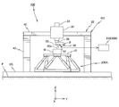
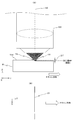
- FIG. 1 shows the structure of a 1st stage system schematically with a measurement system. It is a perspective view which shows the 1st stage system with which the workpiece
- FIG. 9A is an enlarged view showing the vicinity of the target surface of the workpiece when a beam is irradiated from the condensing optical system to the target portion of the workpiece to form a slit-shaped irradiation region, and FIG. FIG.
- FIG. 10 is a diagram showing the relationship between the slit-shaped irradiation region shown in FIG. 9A and the scanning direction.
- FIG. 10A is an explanatory diagram of an example of a machining mode that can be set in the machining apparatus according to the present embodiment, and FIG. 10B uses the optical blades of mode 1, mode 2, mode 3, and mode 4, respectively.
- FIG. 10C is a diagram for explaining the processing using the mode 5 and mode 6 optical blades. It is a figure which shows arrangement
- FIG. 10A is an explanatory diagram of an example of a machining mode that can be set in the machining apparatus according to the present embodiment
- FIG. 10B uses the optical blades of mode 1, mode 2, mode 3, and mode 4, respectively.
- FIG. 10C is a diagram for explaining the processing using the mode 5 and mode 6 optical blades. It is a figure which
- FIG. 13A is a diagram showing an optical arrangement when measuring the beam intensity distribution on the image plane of the condensing optical system
- FIG. 13B is an optical diagram when measuring the beam intensity distribution on the pupil plane.
- It is a figure which shows arrangement
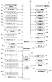
- It is a block diagram which shows the input / output relationship of the control apparatus which mainly comprises the control system of a processing apparatus.
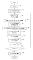
- It is a flowchart corresponding to a series of processing algorithms of a control apparatus.
- It is a figure which shows an example of the measuring apparatus for measuring the intensity distribution of the beam in a process surface.
- FIG. 1 is a block diagram showing the overall configuration of a processing apparatus 100 according to an embodiment.
- the processing apparatus 100 is an apparatus that performs various processes including a removal process (equivalent to a cutting process or a grinding process performed as a machining process) by irradiating a workpiece (also called a workpiece) with a beam (usually a laser beam). It is.
- a removal process equivalent to a cutting process or a grinding process performed as a machining process
- a beam usually a laser beam
- the processing apparatus 100 includes four systems, a first stage system 200A, a second stage system 200B, a transfer system 300, a measurement system 400, and a beam irradiation system 500, and these systems, and controls the entire processing apparatus 100. And a control device 600.
- the conveyance system 300, the measurement system 400, and the beam irradiation system 500 are arranged away from each other in a predetermined direction.
- the transport system 300, the measurement system 400, and the beam irradiation system 500 are arranged away from each other in the X-axis direction (see FIG. 2) described later.
- FIG. 2 schematically shows the configuration of the first stage system 200A together with the measurement system 400.
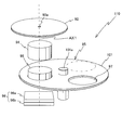
- FIG. 3 is a perspective view of the first stage system 200A on which the workpiece W is mounted.
- the horizontal direction in FIG. 2 is defined as the Y-axis direction
- the direction orthogonal to the paper surface is defined as the X-axis direction
- the direction orthogonal to the X-axis and Y-axis is defined as the Z-axis direction.
- the rotation (tilt) direction will be described as ⁇ x, ⁇ y, and ⁇ z directions, respectively.
- the first stage system 200A changes the position and posture of the workpiece W. Specifically, by moving a table, which will be described later, on which the work W is mounted in 6-degree-of-freedom directions (X-axis, Y-axis, Z-axis, ⁇ x, ⁇ y, and ⁇ z directions), the 6-degree-of-freedom direction of the work W Change the position of.
- the positions of the three degrees of freedom in the ⁇ x, ⁇ y, and ⁇ z directions are collectively referred to as “posture” as appropriate for the table or workpiece, and the remaining three degrees of freedom (X-axis, Y-axis) corresponding thereto.
- position in the direction of the axis and the Z-axis) is collectively referred to as “position” where appropriate.
- the first stage system 200A includes a Stewart platform type 6-degree-of-freedom parallel link mechanism as an example of a drive mechanism that changes the position and orientation of the table.
- the first stage system 200A is not limited to the one that can drive the table in the direction of six degrees of freedom, and is not limited to the parallel link mechanism.
- the first stage system 200A (except the stator of a planar motor described later) is on a base BS installed on the floor F so that the upper surface thereof is substantially parallel to the XY plane. Is arranged.
- the first stage system 200 ⁇ / b> A has a regular hexagonal slider 10 that forms a base platform, a table 12 that forms an end effector, and six sliders 10 and 12 that connect the table 12.
- Telescopic rods (links) 14 1 to 14 6 and telescopic mechanisms 16 1 to 16 6 provided on the rods 14 1 to 14 6 to expand and contract the rods (not shown in FIG. 3, see FIG. 14) And have.
- the first stage system 200A has a structure in which the movement of the table 12 can be controlled in six degrees of freedom in a three-dimensional space by adjusting the lengths of the rods 14 1 to 14 6 independently by the extension mechanisms 16 1 to 16 6. It has become. Since the first stage system 200A includes a Stewart platform type 6-degree-of-freedom parallel link mechanism as a drive mechanism for the table 12, it has features such as high accuracy, high rigidity, large support force, and easy inverse kinematics calculation. There is.
- the beam irradiation system 500 in order to perform a desired processing on the workpiece at the time of processing the workpiece, for example, the beam irradiation system 500, more specifically, a beam from an illumination optical system to be described later.
- the position and orientation of the workpiece W (table 12) are controlled.
- the beam from the illumination optical system may be movable, or both the beam and the workpiece (table) may be movable.
- the beam irradiation system 500 since the beam irradiation system 500 has a complicated configuration, it is easier to move the workpiece.
- the table 12 is made of a plate member having a shape that is obtained by cutting off each vertex of the equilateral triangle.
- a workpiece W to be processed is mounted on the upper surface of the table 12.
- the table 12 is provided with a chuck mechanism 13 (not shown in FIG. 3, refer to FIGS. 4 and 14) for fixing the workpiece W.
- a mechanical chuck or a vacuum chuck is used as the chuck mechanism 13.
- the table 12 is provided with a measuring device 110 (see FIGS. 11 and 12) including a circular measuring member 92 shown in FIG. The measuring device 110 will be described in detail later.
- the table 12 is not limited to the shape shown in FIG. 3, and may have any shape such as a rectangular plate shape or a disk shape.
- each end of each of the rods 14 1 to 14 6 is connected to the slider 10 and the table 12 via the universal joint 18. Further, the rods 14 1 and 14 2 are connected in the vicinity of one vertex position of the triangle of the table 12, and the slider 10 and the rods 14 1 and 14 2 constitute an approximate triangle. Yes. Similarly, the rods 14 3 and 14 4 and the rods 14 5 and 14 6 are respectively connected in the vicinity of the remaining vertex positions of the triangle of the table 12, and the slider 10, the rods 14 3 , 14 4 , and the rod 14 are connected. 5 and 14 6 are arranged so as to form an approximate triangle.
- Each of these rods 14 1 to 14 6 includes a first shaft member 20 and a second shaft member 22 that are relatively movable in the respective axial directions, as representatively shown for rod 14 1 in FIG.
- One end (lower end) of the first shaft member 20 is attached to the slider 10 via the universal joint 18, and the other end (upper end) of the second shaft member 22 has a universal joint on the table 12. Is attached through.
- a stepped cylindrical hollow portion is formed inside the first shaft member 20, and a bellows type air cylinder, for example, is accommodated at the lower end side of the hollow portion.
- a pneumatic circuit and an air pressure source are connected to the air cylinder. Then, by controlling the air pressure of the compressed air supplied from the air pressure source via the pneumatic circuit, the internal pressure of the air cylinder is controlled so that the piston of the air cylinder is reciprocated in the axial direction. It has become.
- the return process uses gravity that acts on the piston when it is incorporated into the parallel link mechanism.
- an armature unit (not shown) composed of a plurality of armature coils arranged in the axial direction is disposed on the upper end side in the hollow portion of the first shaft member 20.
- the second shaft member 22 has one end (lower end) inserted into the hollow portion of the first shaft member 20.
- One end of the second shaft member 22 is formed with a small-diameter portion having a smaller diameter than the other portions, and a circular-shaped mover yoke made of a magnetic member is provided around the small-diameter portion. It has been.
- On the outer peripheral portion of the mover yoke a hollow columnar shape composed of a plurality of permanent magnets having the same dimensions, that is, a cylindrical magnet body is provided.
- a hollow cylindrical magnet unit is constituted by the mover yoke and the magnet body.
- the armature unit and the magnet unit constitute a shaft motor that is a kind of electromagnetic force linear motor.
- a sinusoidal drive current having a predetermined period and a predetermined amplitude is supplied to each coil of the armature unit, which is a stator, so that a gap between the magnet unit and the armature unit is obtained.
- the second shaft member 22 is driven relative to the first shaft member 20 in the axial direction by Lorentz force (driving force) generated by electromagnetic interaction, which is a kind of electromagnetic interaction.
- the first shaft member 20 and the second shaft member 22 are relatively driven in the axial direction by the air cylinder and the shaft motor described above to expand and contract each of the rods 14 1 to 14 6 .
- the aforementioned telescopic mechanisms 16 1 to 16 6 are respectively configured.
- the magnet unit that is the mover of the shaft motor is supported in a non-contact manner with respect to the armature unit that is the stator via an air pad provided on the inner peripheral surface of the first shaft member 20.
- each of the rods 14 1 to 14 6 has an absolute linear that detects the axial position of the second shaft member 22 with respect to the first shaft member 20.
- Encoders 24 1 to 24 6 are provided, and outputs of the linear encoders 24 1 to 24 6 are supplied to the control device 600 (see FIG. 14).
- the axial position of the second shaft member 22 detected by the linear encoders 24 1 to 24 6 corresponds to the length of each of the rods 14 1 to 14 6 .
- the telescopic mechanisms 16 1 to 16 6 are controlled by the control device 600 (see FIG. 14).
- the details of the configuration of the parallel link mechanism similar to the first stage system 200A of the present embodiment are disclosed in, for example, US Pat. No. 6,940,582, and the control device 600 is disclosed in the above US patent specification.
- the position and posture of the table 12 are controlled via the expansion / contraction mechanisms 16 1 to 16 6 using inverse kinematics calculation.
- the telescopic mechanisms 16 1 to 16 6 respectively provided on the rods 14 1 to 14 6 are an air cylinder arranged in series (or parallel) with each other and a shaft motor which is a kind of electromagnetic force linear motor. Therefore, in the control device 600, the table 12 can be moved coarsely and largely and finely moved finely by the shaft motor by the pneumatic pressure control of the air cylinder. As a result, the position of the table 12 in the 6-degree-of-freedom direction (that is, the position and orientation) can be accurately controlled in a short time.
- each of the rods 14 1 to 14 6 has an air pad that supports the magnet unit, which is the mover of the shaft motor, in a non-contact manner with respect to the armature unit, which is the stator. Friction, which is a non-linear component when controlling expansion and contraction, can be avoided, whereby the position and posture of the table 12 can be controlled with higher accuracy.
- a shaft motor is used as the electromagnetic force linear motor constituting the expansion / contraction mechanisms 16 1 to 16 6 , and the shaft motor uses a magnet unit in which a cylindrical magnet is used on the mover side. Therefore, magnetic flux (magnetic field) is generated in all directions in the radial direction of the magnet, and the magnetic flux in all directions can be contributed to the generation of Lorentz force (driving force) due to electromagnetic interaction. Compared to a motor or the like, a clearly large thrust can be generated, and the size can be easily reduced as compared to a hydraulic cylinder or the like.
- each rod includes a shaft motor, it is possible to simultaneously realize a reduction in size and weight and an improvement in output, which can be suitably applied to the processing apparatus 100.
- control device 600 can suppress low-frequency vibrations by controlling the air pressures of the air cylinders that constitute the expansion and contraction mechanisms, and can insulate high-frequency vibrations by controlling the current to the shaft motor.
- the first stage system 200A further includes a planar motor 26 (see FIG. 14).
- a mover of a planar motor 26 made of a magnet unit (or coil unit) is provided on the bottom surface of the slider 10.
- a flat surface made of a coil unit (or magnet unit) is formed inside the base BS.
- the stator of the motor 26 is accommodated.
- a plurality of air bearings are provided on the bottom surface of the slider 10 so as to surround the mover, and the slider 10 is finished with high flatness (guide surface) by the plurality of air bearings. It is levitated and supported above via a predetermined clearance (gap or gap).
- the slider 10 is driven in the XY plane in a non-contact manner with respect to the upper surface of the base BS by electromagnetic force (Lorentz force) generated by electromagnetic interaction between the stator and the movable element of the planar motor 26.
- the first stage system 200A can freely move the table 12 between the arrangement positions of the measurement system 400, the beam irradiation system 500, and the transfer system 300, as shown in FIG.
- the first stage system 200A may include a plurality of tables 12 on which the workpieces W are mounted. For example, while processing using the beam irradiation system 500 is performed on a workpiece held on one of a plurality of tables, measurement using the measurement system 400 is performed on a workpiece held on another table. May be performed.
- each slider 10 may be fixed on the base BS. Even when a plurality of tables 12 are provided, each table 12 is movable in the direction of 6 degrees of freedom, and the position in the direction of 6 degrees of freedom can be controlled.
- the planar motor 26 is not limited to the air levitation method, and a magnetic levitation method planar motor may be used. In the latter case, the slider 10 need not be provided with an air bearing. As the planar motor 26, either a moving magnet type or a moving coil type can be used.
- the control device 600 controls the slider 10 in the X and Y two-dimensional directions on the base BS by controlling at least one of the magnitude and direction of the current supplied to each coil of the coil unit constituting the planar motor 26. Can move.
- the first stage system 200A includes a position measurement system 28 (see FIG. 14) that measures position information of the slider 10 in the X-axis direction and the Y-axis direction.
- a position measurement system 28 (see FIG. 14) that measures position information of the slider 10 in the X-axis direction and the Y-axis direction.
- a two-dimensional absolute encoder can be used as the position measurement system 28, Specifically, a two-dimensional scale having a belt-like absolute cord with a predetermined width over the entire length in the X-axis direction is provided on the upper surface of the base BS, and a light source such as a light emitting element is provided on the bottom surface of the slider 10 correspondingly.
- a configured X head and Y head are provided.
- As a two-dimensional scale for example, on a non-reflective substrate (reflectance 0%), a plurality of square reflecting portions (with a constant period) along two directions (X-axis direction and Y-axis direction) orthogonal to each other ( Marks) are two-dimensionally arranged, and the reflection characteristic (reflectance) of the reflection portion has a gradation according to a predetermined rule.
- the two-dimensional absolute encoder for example, the same configuration as the two-dimensional absolute encoder disclosed in US Patent Application Publication No. 2014/0070073 may be adopted. According to the absolute type two-dimensional encoder having the same configuration as that of US Patent Application Publication No. 2014/0070073, it is possible to measure two-dimensional position information with high accuracy equivalent to that of a conventional incremental encoder. Since it is an absolute encoder, unlike the incremental encoder, origin detection is not required. Measurement information of the position measurement system 28 is sent to the control device 600.
- position information in this embodiment, shape in the three-dimensional space
- the target surface for example, the upper surface
- the target surface means a surface on which a processing target site is provided. Therefore, when the control device 600 measures the shape information of at least a part of the target surface on the workpiece W, the measurement result and the linear encoders 24 1 to 24 provided on the rods 14 1 to 14 6 at the time of the measurement are displayed.
- the reference of the processing apparatus 100 It can be associated with a coordinate system (hereinafter referred to as a table coordinate system).
- a coordinate system hereinafter referred to as a table coordinate system.
- absolute encoders are used as the linear encoders 24 1 to 24 6 and the position measuring system 28, so that it is not necessary to return to the origin, so that resetting is easy.
- the above-described measurement system 400 should be used for enabling position control in the 6-DOF direction with respect to the target value of the target part of the workpiece W by open-loop control of the position in the 6-DOF direction of the table 12.
- the position information in the three-dimensional space is not limited to the shape, but may be at least three-point position information corresponding to the shape of the target surface.
- planar motor 26 is used as the driving device that moves the slider 10 in the XY plane.
- a linear motor may be used instead of the planar motor 26.
- a position measurement system for measuring the position information of the slider 10 may be configured by an absolute linear encoder.
- the position measurement system for measuring the position information of the slider 10 is not limited to the encoder, and may be configured using an interferometer system.
- the mechanism for moving the table is configured using a planar motor that moves the slider in the XY plane and a Stewart platform type 6-degree-of-freedom parallel link mechanism in which the base platform is configured by the slider.
- the present invention is not limited to this, and other types of parallel link mechanisms or mechanisms that move the table may be configured using mechanisms other than the parallel link mechanism.
- a slider that moves in the XY plane and a Z tilt drive mechanism that moves the table 12 in the Z-axis direction and the tilt direction with respect to the XY plane on the slider may be employed.
- the table 12 is supported from below by, for example, a universal joint or other joint at each vertex position of a triangle, and each supporting point can be driven independently in the Z-axis direction.
- a mechanism having two actuators such as a voice coil motor
- the configuration of the mechanism for moving the table of the first stage system 200A is not limited to these, and the table (movable member) on which the workpiece is placed is placed in the three-degree-of-freedom direction in the XY plane and the Z-axis. Any slider that moves in the XY plane may be used as long as it can be driven in the direction of at least five degrees of freedom in the direction and the tilt direction with respect to the XY plane.
- the first stage system may be configured by a table and a robot that moves the table.
- the measurement system that measures the position of the table is configured using a combination of an absolute linear encoder or a combination of the linear encoder and an absolute rotary encoder, the resetting is facilitated. be able to.
- the table 12 can be driven in the direction of 3 degrees of freedom in the XY plane, the direction of the Z axis, and the direction of inclination ( ⁇ x or ⁇ y) with respect to the XY plane in at least 5 degrees of freedom.
- a system may be adopted.
- the table 12 itself may be supported by levitation (non-contact support) via a predetermined clearance (gap or gap) on the upper surface of a support member such as the base BS by air levitation or magnetic levitation.
- the table moves in a non-contact manner with respect to a member that supports the table, which is extremely advantageous in terms of positioning accuracy, and greatly contributes to improvement in processing accuracy.
- the measurement system 400 measures the three-dimensional position information of the work for associating the position and orientation of the work mounted on the table 12 with the table coordinate system, for example, the shape.
- the measurement system 400 includes a laser non-contact type three-dimensional measuring device 401.
- the three-dimensional measuring instrument 401 is provided at the frame 30 installed on the base BS, the head unit 32 attached to the frame 30, the Z-axis guide 34 attached to the head unit 32, and the lower end of the Z-axis guide 34.
- a sensor unit 38 connected to the lower end of the rotation mechanism 36.
- the frame 30 includes a horizontal member 40 extending in the Y-axis direction and a pair of column members 42 that support the horizontal member 40 from below at both ends in the Y-axis direction.
- the head portion 32 is attached to the horizontal member 40 of the frame 30.
- the Z-axis guide 34 is mounted on the head portion 32 so as to be movable in the Z-axis direction, and is driven in the Z-axis direction by a Z drive mechanism 44 (not shown in FIG. 2, see FIG. 14).
- the position of the Z-axis guide 34 in the Z-axis direction (or the displacement from the reference position) is measured by a Z encoder 46 (not shown in FIG. 2, see FIG. 14).
- the rotation mechanism 36 rotates the sensor unit 38 parallel to the Z axis within a predetermined angle range (for example, a range of 90 degrees ( ⁇ / 2) or 180 degrees ( ⁇ )) with respect to the head unit 32 (Z-axis guide 34). It can be rotated continuously (or in steps of a predetermined angle) around the central axis.
- a predetermined angle range for example, a range of 90 degrees ( ⁇ / 2) or 180 degrees ( ⁇ )
- the rotation center axis of the sensor unit 38 by the rotation mechanism 36 coincides with the center axis of line light emitted from an irradiation unit (described later) constituting the sensor unit 38.
- the rotation angle from the reference position of the sensor unit 38 by the rotation mechanism 36 is measured by a rotation angle sensor 48 such as a rotary encoder (not shown in FIG. 2, see FIG. 14). Is done.
- the sensor unit 38 is configured to irradiate a test object (work W in FIG. 2) placed on the table 12 with line light for irradiating the line light, and to irradiate the line light with the irradiation unit 50.
- a detection unit 52 that detects the surface of the test object on which the surface (line) appears is mainly configured.
- the sensor unit 38 is connected to an arithmetic processing unit 610 that obtains the shape of the test object based on the image data detected by the detection unit 52.
- the arithmetic processing unit 610 is included in a control device 600 for comprehensively controlling each component of the processing device 100 (see FIGS. 1 and 14).
- the irradiation unit 50 includes a cylindrical lens (not shown) and a slit plate having a thin band-shaped notch, and generates fan-shaped line light 50a upon receiving illumination light from a light source.
- a light source an LED, a laser light source, an SLD (super luminescent diode), or the like can be used.
- the LED when used, the light source can be formed at a low cost.
- a laser light source it is a point light source, so it can produce line light with less aberration, excellent wavelength stability, a small half-value width, and a filter with a small half-value width can be used to cut stray light. Can be reduced.
- the detection part 52 is for imaging the line light 50a projected on the surface of the test object (work W) from a direction different from the light irradiation direction of the irradiation part 50.
- the detection unit 52 includes an imaging lens (not shown), a CCD, and the like. As described later, the detection unit 52 moves the table 12 and images the test object (work W) every time the line light 50a is scanned at a predetermined interval. It is like that.
- the positions of the irradiation unit 50 and the detection unit 52 are such that the incident direction of the line light 50a on the surface of the test object (work W) with respect to the detection unit 52 and the light irradiation direction of the irradiation unit 50 form a predetermined angle ⁇ . It is determined to make.
- the predetermined angle ⁇ is set to 45 degrees, for example.
- the image data of the test object (work W) imaged by the detection unit 52 is sent to the arithmetic processing unit 610, where a predetermined image calculation process is performed to determine the height of the surface of the test object (work W).
- the calculated three-dimensional shape (surface shape) of the test object (work W) is obtained.
- the arithmetic processing unit 610 uses the light cutting surface based on the position information of the light cutting surface (line) by the line light 50a deformed according to the unevenness of the testing object (work W) in the image of the testing object (work W).
- the control device 600 moves the table 12 in a direction substantially perpendicular to the longitudinal direction of the line light 50a projected on the test object (work W), so that the line light 50a is transferred to the test object (work).
- the surface of W) is scanned.
- the control device 600 detects the rotation angle of the sensor unit 38 with the rotation angle sensor 48, and moves the table 12 in a direction substantially perpendicular to the longitudinal direction of the line light 50a based on the detection result.
- the table 12 is moved when measuring the shape or the like of the test object (work W). As a precondition, the work W is held below the sensor unit 38 of the measurement system 400.
- the reference state is a state in which, for example, all of the rods 14 1 to 14 6 have a length corresponding to the neutral point of the expansion / contraction stroke range (or the minimum length).
- the Z axis of the table 12, ⁇ x, ⁇ y And ⁇ z (Z, ⁇ x, ⁇ y, ⁇ z) (Z 0 , 0, 0 , 0).
- the position (X, Y) of the table 12 in the XY plane coincides with the X and Y positions of the slider 10 measured by the position measurement system 28.
- the position of the table 12 in the 6-degree-of-freedom direction is managed on the table coordinate system by the control device 600 including this measurement. That is, the control device 600 controls the planar motor 26 based on the measurement information of the position measurement system 28 and controls the expansion / contraction mechanisms 16 1 to 16 6 based on the measurement values of the linear encoders 24 1 to 24 6. Thus, the position of the table 12 in the direction of 6 degrees of freedom is controlled.
- the line light 50 a irradiated from the irradiation unit 50 of the sensor unit 38 to the test object (work W) is converted into the sensor unit 38. It is desirable to arrange in a direction orthogonal to the relative movement direction with respect to the table 12 (test object (work W)). For example, in FIG. 2, when the relative movement direction between the sensor unit 38 and the test object (work W) is set in the Y-axis direction, it is desirable to arrange the line light 50a along the X-axis direction.
- a rotation mechanism 36 is provided so that the direction of the line light 50a and the relative movement direction described above can always be orthogonal to each other.
- the three-dimensional measuring instrument 401 described above is configured in the same manner as the shape measuring apparatus disclosed in, for example, US Patent Application Publication No. 2012/01085787. However, the scanning of the line light in the direction parallel to the X and Y planes with respect to the test object is performed by the movement of the sensor unit in the apparatus described in US 2012/0105867. This embodiment is different in that it is performed by moving the table 12. In the present embodiment, either the Z-axis guide 34 or the table 12 may be driven when the line light is scanned in the direction parallel to the Z-axis.
- a line-shaped projection pattern composed of one line light is projected onto the surface of the test object, and the line-shaped projection pattern is converted into a line-shaped projection pattern.
- the line-shaped projection pattern projected onto the test object is imaged from an angle different from the projection direction.
- the height from the reference plane of the surface of the test object is calculated from the captured image of the surface of the test object for each pixel in the longitudinal direction of the linear projection pattern using the principle of triangulation, etc.
- the three-dimensional shape of the surface is obtained.
- the three-dimensional measuring machine constituting the measurement system 400 for example, an apparatus having the same configuration as the optical probe disclosed in US Pat. No. 7,009,717 can be used.
- the optical probe is composed of two or more optical groups, and includes two or more visual field directions and two or more projection directions.
- One optical group includes one or more field directions and one or more projection directions. At least one field direction and at least one projection direction are different between the optical groups, and the data obtained by the field direction is the same optical group. It is generated only by the pattern projected according to the projection direction.
- the measurement system 400 may include a mark detection system 56 (see FIG. 14) that optically detects an alignment mark instead of the above-described three-dimensional measuring device 401 or in addition to the above-described three-dimensional measuring device. .
- the mark detection system 56 can detect, for example, an alignment mark formed on the workpiece.
- the control device 600 calculates the position and orientation of the workpiece (or table 12) by accurately detecting the center positions (three-dimensional coordinates) of at least three alignment marks using the mark detection system 56, respectively.
- the mark detection system 56 can be configured to include a stereo camera, for example.
- control device 600 scans the surface (target surface) of the workpiece W using the three-dimensional measuring device 401 as described above, and acquires the surface shape data. Then, the control device 600 performs a least square process using the surface shape data, and associates the three-dimensional position and orientation of the target surface on the workpiece with the table coordinate system.
- the control device 600 since the position of the table 12 in the six-degree-of-freedom direction is managed on the table coordinate system by the control device 600, including the above-described measurement with respect to the test object (work W), the three-dimensional position of the work And the position of the workpiece 12 in the direction of 6 degrees of freedom (that is, the position and posture) are controlled by the open loop of the table 12 according to the table coordinate system, including the time of machining, It can be performed by controlling.
- FIG 4 shows the beam irradiation system 500 together with the mask stage 15 as a holding member for holding the mask M and the table 12 on which the workpiece W is mounted.
- the mask stage 15 constituting a part of the second stage system 200B holds a mask M as an opening member having a plurality of openings (opening patterns).
- a mask provided with a through hole may be used as the opening, or a light shielding material such as chromium is vapor-deposited so that the opening is formed on the upper surface or the lower surface of a base material (such as synthetic quartz) that can transmit the beam.
- a mask may be formed.
- the mask M is permanently installed on the mask stage 15, but a configuration in which the mask on the mask stage 15 can be replaced may be adopted.
- the second stage system 200B can change the position of the mask M with respect to the condensing optical system 530 by moving the mask stage 15 as will be described later.
- the mask stage 15 on which the mask M is permanently installed is moved to each of four degrees of freedom directions (X axis, Y axis, Z axis, and ⁇ z) by a mask stage drive system 17 (not shown in FIG. 4, see FIG. 14).
- the position of the mask M in the direction of 4 degrees of freedom is changed.
- the position information of the mask stage 15 in the X-axis direction, Y-axis direction, ⁇ z direction, and Z-axis direction is obtained by, for example, a mask stage position measurement system 19 (not shown in FIG. 4, see FIG. 14) including an interferometer system. It is measured with a resolution of about 0.25 to 1 nm.
- the mask stage position measurement system 19 may be configured by an encoder system or other sensors.
- the mask stage drive system 17 is constituted by, for example, a magnetic levitation type planar motor.
- the mask stage drive system may be configured by a linear motor system configured to be able to drive the mask stage 15 in the Z-axis direction in addition to the X-axis direction and the Y-axis direction.
- the mask stage drive system 17 can move the mask stage 15 in the direction of 4 degrees of freedom, but may move the mask stage 15 in the direction of 6 degrees of freedom, or if the opening can be changed.
- the mask stage 15 may be configured to be movable only in the X-axis direction or the Y-axis direction.
- a film-like or plate-like mask is used as the mask M.
- a stencil mask can also be used.
- the mask M may be formed of a low thermal expansion material.
- the mask stage 15 is formed with a through-hole 15a in the vertical direction (Z-axis direction) serving as a beam path, and the mask M is disposed above the through-hole 15a.
- FIG. 5 a plan view of the mask M is shown. As shown in FIG.
- the masks M each extend in the X-axis direction, have the same line width (for example, 10 ⁇ m), and have a plurality of types having different lengths in the X-axis direction (for example, 4 A plurality of types of slit-shaped openings, each extending in the Y-axis direction, having the same line width (for example, 10 ⁇ m) and different lengths in the Y-axis direction (for example, four types) , Multiple types (for example, four types) of circular openings (pinhole-shaped openings) having different diameters, and a plurality of types (for example, four types) of square openings having different side lengths are formed. .
- the opening PAc is a pinhole-shaped opening having a diameter of 10 ⁇ m as an example.
- the shape of the opening is not limited to the slit shape, the circular shape, and the square shape, but may be other shapes such as a rectangular shape and a polygonal shape, and includes at least one of a slit shape opening, a circular opening shape, and a square opening shape. It is not necessary.
- the number (type) of openings of each shape is not limited to four. For example, the number of circular openings may be one and the number of square openings may be three.
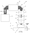
- the beam irradiation system 500 includes a light source system 510, an illumination optical system 520 that irradiates the mask M with a beam emitted from the light source system, and a beam that has passed through the mask M. And a condensing optical system 530 that condenses the light.
- the light source system 510 includes a light source unit 60, a light guide fiber 62 connected to the light source unit 60, a double fly's eye optical system 64 disposed on the emission side of the light guide fiber 62, A condenser lens system 66.
- the light source unit 60 includes a housing 68 and a plurality of laser units 70 housed in the housing 68 and arranged in a matrix in parallel with each other.
- the laser unit 70 various lasers that perform pulse oscillation or continuous wave oscillation operation, for example, a light source unit such as a carbon dioxide laser, an Nd: YAG laser, a fiber laser, or a GaN semiconductor laser can be used.
- the laser used as the laser unit 70 may be a nanosecond laser, a picosecond laser, or a femtosecond laser.
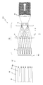
- the light guide fiber 62 is a fiber bundle configured by randomly bundling a large number of optical fiber strands, and includes a plurality of incident ports 62a individually connected to the emission ends of the plurality of laser units 70, and an incident port 62a. And an injection part 62b having a larger number of injection ports.
- the light guide fiber 62 receives a plurality of laser beams emitted from each of the plurality of laser units 70 (hereinafter, abbreviated as “beams” as appropriate) through each incident port 62a and distributes the laser beams to a plurality of emission ports. Then, at least a part of each laser beam is emitted from a common exit.
- the light guide fiber 62 mixes and emits the beams emitted from each of the plurality of laser units 70.
- the total output can be increased according to the number of laser units 70.
- a plurality of laser units need not be used.
- the emitting portion 62b has a cross-sectional shape similar to the overall shape of the incident end of the first fly-eye lens system that constitutes the incident end of the double fly's eye optical system 64 described below, and the incident portion 62b projects within the cross section.
- the outlets are provided in a substantially uniform arrangement.
- the light guide fiber 62 also serves as a shaping optical system that shapes the beam mixed as described above so as to be similar to the overall shape of the incident end of the first fly-eye lens system.
- the double fly's eye optical system 64 is for uniformizing the cross-sectional intensity distribution of the beam (illumination light).
- the first fly eye optical system 64 is sequentially arranged on the beam path (optical path) of the laser beam behind the light guide fiber 62.
- An eye lens system 72, a lens system 74, and a second fly eye lens system 76 are included.
- a diaphragm is provided around the second fly-eye lens system 76.
- the incident surface of the first fly-eye lens system 72 and the incident surface of the second fly-eye lens system 76 are set optically conjugate with each other.
- the exit-side focal plane of the first fly-eye lens system 72 (a surface light source described later is formed), and the exit-side focal plane of the second fly-eye lens system 76 (a surface light source described later is formed).
- the pupil plane (incidence pupil) PP2 of the condensing optical system 530 are optically conjugate with each other.
- the beam mixed by the light guide fiber 62 enters the first fly eye lens system 72 of the double fly eye optical system 64.
- a surface light source that is, a secondary light source composed of a large number of light source images (point light sources) is formed on the exit-side focal plane of the first fly-eye lens system 72.
- Laser light from each of these many point light sources enters the second fly's eye lens system 76 via the lens system 74.
- a surface light source (tertiary light source) is formed on the exit-side focal plane of the second fly's eye lens system 76 in which a large number of minute light source images are uniformly distributed within a region having a predetermined shape.
- the exit-side focal plane of the first fly-eye lens system 72 moves from the exit surface of the first fly-eye lens system 72 to the beam exit side in order to reduce the possibility that the first fly-eye lens system 72 is damaged by the beam. It may be a distant surface.
- the secondary light source by the first fly-eye lens system 72 is formed at a position deviated from the exit surface of the first fly-eye lens system 72.
- the exit-side focal plane of the second fly-eye lens system 76 may be a surface that is separated from the exit surface of the second fly-eye lens system 76 toward the beam exit side.
- the tertiary light source by the second fly-eye lens system 76 is formed at a position deviated from the exit surface of the second fly-eye lens system 76.
- the condenser lens system 66 has a front focal point positioned at or near the exit surface of the second fly-eye lens system 76, and emits the laser light emitted from the tertiary light source as a beam having a uniform illuminance distribution. .
- the beam emitted from the condenser lens system 66 can be regarded as a parallel beam by optimizing the area of the incident end of the second fly-eye lens system 76, the focal length of the condenser lens system 66, and the like.
- the light source system 510 of the present embodiment includes an illuminance uniformizing optical system including a light guide fiber 62, a double fly's eye optical system 64, and a condenser lens system 66, and a plurality of lasers using the illuminance uniforming optical system.
- the beams emitted from the units 70 are mixed to generate a parallel beam with a uniform cross-sectional illuminance distribution.
- making the cross-sectional illuminance distribution uniform means that the illuminance distribution in the beam cross section of the beam emitted from the illuminance uniformizing optical system is more uniform than the illuminance distribution in the beam cross section of the beam incident on the illuminance uniformizing optical system. It may also include being closer to the state.
- the illuminance uniformizing optical system is not limited to the above-described configuration.
- the illuminance uniforming optical system may be configured using a rod integrator, a collimator lens system, or the like.
- the light source unit 60 of the light source system 510 is connected to the control device 600 (see FIG. 14), and the control device 600 individually controls on / off of the plurality of laser units 70 constituting the light source unit 60. Thereby, the light quantity (laser output) of the laser beam irradiated to the workpiece
- the illumination optical system 520 includes an optical device 78, a first partial illumination optical system 79, and a mirror array 80 that are sequentially arranged on the optical path of the parallel beam from the light source system 510 (condenser lens system 66). And a second partial illumination optical system 82.
- the optical device 78 can change the intensity distribution of the cross section of the parallel beam from the light source system 510 (condenser lens system 66).
- the optical device 78 is configured by a mirror array which is a kind of spatial light modulator (SLM: Spatial Light Modulator).
- SLM Spatial Light Modulator
- the spatial light modulator is a general term for elements that spatially modulate the amplitude (intensity), phase, or polarization state of light traveling in a predetermined direction.
- the optical device 78 is also referred to as a second mirror array 78.
- the second mirror array 78 can change the cross-sectional intensity distribution (illumination shape) on the pupil plane PP1 of the illumination optical system 520 of the parallel beam from the light source system 510.
- the above-described mirror array 80 is referred to as a first mirror array 80 (may be referred to as an optical device 80) for identification from the second mirror array 78.
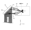
- the second mirror array 78 has a base member 78A having a surface (hereinafter referred to as a reference surface for convenience) that forms 45 degrees ( ⁇ / 4) with respect to the XY plane and the XZ plane.
- K I ⁇ J
- a drive unit 78B (not shown in FIG. 7, see FIG. 14) including K actuators (not shown) that individually move the mirror elements 81 i, j .
- Each mirror element 81 i, j of the second mirror array 78 is configured to be rotatable, for example , about a rotation axis parallel to one diagonal line of each mirror element 81 i, j , and its reflection surface is inclined with respect to the reference plane
- the angle can be set to an arbitrary angle within a predetermined angle range.
- the angle of the reflecting surface of each mirror element is measured by a sensor that detects the rotation angle of the rotating shaft, for example, a rotary encoder 83 i, j (not shown in FIG. 7, refer to FIG. 14).
- the drive unit 78B includes, for example, an electromagnet or a voice coil motor as an actuator, and each mirror element 81 i, j is driven by the actuator and operates with a very high response.
- Each of the plurality of mirror elements 81 i, j constituting the second mirror array 78 is illuminated by a parallel beam from the light source system 510, and a plurality of reflected beams (parallel beam) in a direction according to the inclination angle of the reflecting surface thereof. ) LB is emitted and incident on the first partial illumination optical system 79 (see FIG. 7).
- the first partial illumination optical system 79 includes a plurality of lenses including a relay lens, and the pupil plane PP1 of the illumination optical system 520 is disposed therein, for example.
- the first partial illumination optical system 79 includes a partial optical system 791 between the second mirror array 78 and the pupil plane PP1.
- the partial optical system 791 is arranged such that its front focal position is located at or near the surface on which the second mirror array 78 is arranged, and its rear focal position is located at or near the pupil plane PP1,
- the plurality of reflected beams LB are distributed on the pupil plane PP1 in accordance with the traveling directions of the plurality of reflected beams LB from the second mirror array 78.
- the second mirror array 78 can set or change the cross-sectional intensity distribution of the beam on the pupil plane PP1 by adjusting the tilt angle of the reflecting surface of each of the plurality of mirror elements 81 i, j .
- the second mirror array 78 sets the cross-sectional shape of the beam on the pupil plane PP1 (which may be referred to as an illumination shape) by adjusting the tilt angle of the reflecting surface of each of the plurality of mirror elements 81 i, j . Or it can be changed.
- the pupil plane PP1 is a conjugate plane of the pupil plane (incident pupil plane) PP2 of the condensing optical system 530.
- the partial optical system 791 can also be regarded as an optical system that converts the angle of the incident beam into a position on the exit side.
- the optical device 78 is not limited to a spatial light modulator such as a mirror array.
- a plurality of types of aperture stops are formed on a rotatable disk member, and the plurality of types of aperture stops are exchanged on the beam optical path.
- It can also be configured by an illumination system aperture stop plate or the like that can be arranged.
- the illumination system aperture stop plate may be disposed on or near the pupil plane PP1 in the first partial illumination optical system 79, or may be disposed on or near the pupil plane PP2 of the condensing optical system 530. In this case, the optical device 78 may not be provided.
- the second mirror array 78 is located at or near a surface conjugate with the image surface (processing surface MP) of the condensing optical system 530 and a part of the parallel beam from the light source system 510 (for example, Since some of the mirror elements (also referred to as mirrors as appropriate) can be prevented from entering the illumination optical system 520, the processing beam on the image plane (processing surface MP) of the condensing optical system 530 can be prevented. It is possible to adjust the intensity or the intensity distribution. For example, the intensity distribution in the irradiation region of the processing beam from the condensing optical system 530 can be adjusted on the image plane (processing surface MP) of the condensing optical system 530.
- the parallel beam passing through the optical device (second mirror array as an example) 78 is, as will be described later, a first partial illumination optical system 79, a first mirror array 80, and a second partial illumination optical system 82.
- the pupil plane PP1 of the illumination optical system 520 and the pupil plane of the condensing optical system 530 are changed by changing the cross-sectional intensity distribution of the parallel beam from the light source system 510 using an optical device (second mirror array as an example) 78. (Ingoing pupil) It is possible to change the intensity distribution of the beam at PP2, that is, the sectional shape of the beam.
- the optical device 78 is disposed at a position conjugate to or near the image plane (processing surface MP) of the condensing optical system 530, the optical device 78 is used to cross-section the parallel beam from the light source system 510.
- the intensity distribution it is also possible to change the intensity distribution of the beam emitted from the condensing optical system 530 substantially on the image plane of the condensing optical system 530. For example, by setting the tilt angle of a part of the mirrors of the second mirror array 78 so that the beam reflected by the mirror does not enter the illumination optical system 520, the beam on the image plane (processed surface MP) is set. The intensity distribution in the irradiated area can be changed.
- the optical device 78 is arranged conjugate to or near the surface on which the opening of the mask M is arranged, the optical device 78 is used to convert the cross-sectional intensity distribution of the parallel beam from the light source system 510.
- the optical device 78 is used to convert the cross-sectional intensity distribution of the parallel beam from the light source system 510.
- a plurality of reflected beams (parallel beams) LB emitted from the mirror elements 81 i, j of the second mirror array 78 in a direction corresponding to the inclination angle of the reflecting surface are incident on the pupil plane PP1 of the illumination optical system 520,
- the cross-sectional intensity distribution (that is, the cross-sectional shape and the illumination shape) on the pupil plane PP1 is set according to the inclination angle of the reflecting surface of each mirror element 81 i, j of the second mirror array 78.
- the first partial illumination optical system 79 irradiates a beam having the set cross-sectional intensity distribution onto the first mirror array 80 arranged at a position conjugate with or near the pupil plane PP1 of the illumination optical system 520.
- the first mirror array 80 has a base member 80A having a plane (hereinafter referred to as a reference plane for convenience) that forms 45 degrees ( ⁇ / 4) with respect to the XY plane and the XZ plane.
- a drive unit 80B (not shown in FIG. 4, see FIG. 14) including M actuators (not shown) that individually move the mirror elements 81p and q , and the directions are opposite to each other. Is configured in the same manner as the second mirror array 78.
- each of the mirror elements 81p and q illuminated by the parallel beam from the first partial illumination optical system 79 corresponds to the inclination angle of the reflecting surface.
- a plurality of reflected beams (parallel beams) LB are emitted in the direction, are incident on the second partial illumination optical system 82, and the beam emitted from the second partial illumination optical system 82 has an arbitrary size and an arbitrary shape (for example, , Spot shape or slit shape etc.) and can be condensed on the mask M.
- the second partial illumination optical system 82 has a front focal position at or near the first mirror array 80, and a rear focal position at or near the mask M (for example, the aperture of the mask M).
- the beam from the illumination optical system 520 can be efficiently incident on the condensing optical system 530 through the mask M.
- the first mirror array 80 may not be provided if the opening of the mask M is irradiated with a beam.
- the condensing optical system 530 has a numerical aperture of N.P. A. Is an optical system with a high NA of 0.5 or more, preferably 0.6 or more, and low aberration.
- a reduction projection lens having NA of 0.75, a projection magnification of 1/10, and a maximum field of 1 mm square is used as the condensing optical system 530.
- the condensing optical system 530 since the condensing optical system 530 has a large aperture, low aberration, and high NA, the mask M is irradiated from the first mirror array 80 via the second partial illumination optical system 82. A plurality of beams that have passed through one aperture can be condensed at at least one position or region on the image plane.
- the beam irradiation system 500 condenses the beam emitted from the condensing optical system 530 into, for example, a spot shape or a slit shape according to the shape of the opening of the mask M. be able to.
- the condensing optical system 530 can reduce and project the aperture pattern on the mask M onto the image plane to form a reduced image of the aperture pattern on the image plane.
- the image of the aperture (beam irradiation region) may be formed on the optical axis of the condensing optical system 530 on the image plane of the condensing optical system 530 or at a position shifted from the optical axis. Also good.
- the opening of the mask M used for processing may be arranged at a position off the optical axis of the condensing optical system 530 so that the beam from the first mirror array 80 is irradiated to the opening.
- the mask stage 15 may be regarded as a part of the mechanism that changes the intensity distribution of the beam on the image plane (processing surface MP) of the condensing optical system 530.
- the condensing optical system 530 is configured by one or a plurality of lenses (in FIG. 4, FIG. 8, etc., one lens is representatively shown), the area of incident light can be increased.
- the numerical aperture N.I. A As compared with the case of using a condensing optical system having a small size, a larger amount of light energy can be taken in. Accordingly, the beam condensed by the condensing optical system 530 according to the present embodiment is extremely sharp and has a high energy density, which directly leads to an increase in machining accuracy when machining a workpiece.
- the processing target surface of the workpiece W provided with the target portion A case where processing (machining processing) is performed while the beam and the workpiece W are relatively scanned in the scanning direction (scanning direction) with the TAS being parallel or perpendicular to the XY plane (also referred to as a target surface as appropriate).
- the table 12 may be moved in at least one of the X-axis direction, Z-axis direction, ⁇ x direction, ⁇ y direction, and ⁇ z direction while the table 12 is moving in the Y-axis direction. Needless to say.
- a slit-shaped aperture for example, an image of the slit-shaped aperture PAa or PAb described above, that is, an irradiation region of the slit-shaped beam (see reference numeral LS in FIG. 9B) , Referred to as the processing surface) MP (for example, see FIGS. 4 and 9A), and the workpiece W is relatively scanned in a direction perpendicular to the longitudinal direction with respect to the beam forming the irradiation region LS. Desired processing (for example, removal processing) can be performed. As a result, an extremely large area (for example, an area of several times to several tens of times) can be processed at once, for example, removal processing compared to the case of scanning a workpiece with a spot-like beam.
- the machining surface MP is a surface after machining the workpiece W (a surface after a part of the workpiece W is removed by a beam).
- the position of the workpiece W is controlled so as to coincide with.
- the surface (target surface TAS) of the workpiece W before processing is shifted from the image surface (processing surface MP) by ⁇ Z in the + Z direction.
- This ⁇ Z may be determined based on at least one of the intensity of the beam, the material of the workpiece W, and the relative scanning speed of the beam and the workpiece.
- the processed surface MP may not coincide with the processed surface of the workpiece W.
- the position of the workpiece W may be controlled so that the target surface TAS of the workpiece W and the machining surface MP substantially coincide.
- the cross-sectional intensity distribution (of the condensing optical system 530) of the pupil plane PP1 of the illumination optical system 520 of the parallel beam from the light source system 510 set using the second mirror array 78 is used.
- the cross-sectional intensity distribution on the pupil plane PP2 and the opening on the mask M the three-dimensional intensity distribution of the beam on the first surface on the exit surface side of the condensing optical system 530 and in the vicinity thereof can be changed. .
- the first surface on the exit surface side of the condensing optical system 530 is a surface on which an image of an opening on the mask M is formed.
- the processing surface MP is an image surface of the condensing optical system 530 (see, for example, FIGS. 4 and 9A), but the processing surface MP may be a surface near the image surface.
- the processing surface MP is perpendicular to the optical axis AX on the exit side of the condensing optical system 530, but may not be perpendicular.
- the beam LB irradiated to the machining surface MP can be said to function in the same manner as a cutting tool used as a tool when cutting the workpiece W or the like. In the book, it is also called a light knife.
- FIG. 10 (A) shows an explanatory diagram of an example of a machining mode that can be set in the machining apparatus 100 according to the present embodiment.
- six modes from mode 1 to mode 6 will be described.
- FIG. 10A in the “illumination shape” diagram, a virtual axis perpendicular to the center (optical axis) of the pupil plane is indicated by a one-dot chain line.
- “illumination shape” is the cross-sectional intensity distribution (cross-sectional shape) of the beam on the pupil plane PP1 of the illumination optical system 520, but the cross-sectional intensity distribution of the beam on the pupil plane PP2 of the condensing optical system 530. (Cross-sectional shape).
- the “front view” and “side view” of the tip of the beam are perpendicular to the optical axis between the condensing optical system 530 and the image plane (processing surface MP). It shows the shape of the tip of the beam (light blade) between the virtual surface and the image surface (processing surface MP). Note that even when a laser beam in a non-visible wavelength band is used, it can be described with reference to FIG.
- Mode 1 is a uniform intensity distribution, a circular illumination shape centered on the optical axis (also called normal illumination) is set, and a slit-like opening having a line width of 10 ⁇ m and a length of 10 mm is set as an opening on the mask M. That is, this is a processing mode for selecting the above-described opening PAa or PAb.
- the selection of an aperture means that an illumination field (of illumination light) in which illumination light is irradiated only on a part of the area on the mask M including the selected aperture using the first mirror array 80. Forming (setting) an irradiation region).
- the first mirror array 80 is used to form the illumination field only in a part of the area on the mask M including the selected aperture.
- the entire beam emitted from the light source system 510 is selected. This is because the loss of laser power is reduced as much as possible by irradiating concentrated pattern portions.
- the shape of the optical blade is an isosceles trapezoid inverted upside down when viewed from the front, the length of the blade is 1 mm, and inverted when viewed from the side.
- the isosceles triangle shape has a cutting edge size of 1 ⁇ m.
- the directions indicated by the coordinate axes respectively shown in the front view and the side view of the optical cutter indicate the scanning direction of the workpiece during processing.
- the scanning direction is the X-axis direction
- the scanning direction is the Y-axis direction.
- Mode 2 is a processing mode in which the above-described slit-shaped opening PAa or PAb is selected as the opening on the mask M, and a semicircular illumination shape having a linear portion corresponding to the longitudinal direction of the selected opening is set.
- the illumination shape in mode 2 has an edge along a virtual axis extending in the left-right direction in FIG. 10A. On the pupil plane, one of the two areas divided by the virtual axis The beam is distributed in the area.
- the semicircular illumination shape in mode 2 can be referred to as a one-time rotationally symmetric illumination shape with respect to the center (optical axis) of the pupil plane.
- a virtual axis extending in the left-right direction on the paper surface corresponds to a direction orthogonal to the workpiece scanning direction on the image plane (XY plane).
- the shape of the optical knife is an isosceles trapezoid inverted upside down as in mode 1, and the length of the blade is 1 mm.
- a right triangle is obtained by halving the vertically inverted isosceles triangle in mode 1.
- the scanning direction is the X-axis direction
- the aperture PAb is selected
- the scanning direction is the Y-axis direction.
- the optical blade is a surface parallel to the optical axis of the condensing optical system 530 on the side of the optical blade in the traveling direction (the direction opposite to the workpiece scanning direction).
- the workpiece and the optical blade relatively move in a direction (a direction parallel to the scanning direction) substantially perpendicular to the surface including the outer edge.
- the illumination shape in mode 2 has an edge along a virtual axis extending in the left-right direction on the paper surface.
- On the pupil plane one side (lower side) of two regions divided by this virtual axis is provided.
- the beam is distributed in the region, there may be another mode in which the beam is distributed in the other (upper) region.
- Mode 3 is a processing mode in which the above-described slit-shaped opening PAa or PAb is selected as the opening on the mask M, and a semicircular illumination shape having a linear portion corresponding to a direction orthogonal to the longitudinal direction of the selected opening is set. It is.
- the illumination shape in mode 3 has an edge along a virtual axis extending in the vertical direction on the paper surface of FIG. 10A, and on the pupil plane, one of the two regions divided by the virtual axis The beam is distributed in the area.
- the semicircular illumination shape in mode 3 can be referred to as an illumination shape that is rotationally symmetric once with respect to the center (optical axis) of the pupil plane.
- the virtual axis extending in the vertical direction on the paper surface corresponds to the workpiece scanning direction on the image plane (XY plane).
- the shape of the light blade is a trapezoidal shape obtained by cutting a right-angled triangular portion at the right end from the isosceles trapezoid inverted in mode 1 when viewed from the front.
- One leg is perpendicular to the upper and lower bases, and the length of the cutting edge is 1 mm as in modes 1 and 2. When viewed from the side, it has an isosceles triangle shape similar to that in mode 1, and the size of the cutting edge is 1 ⁇ m.
- the scanning direction is the X-axis direction
- the scanning direction is the Y-axis direction
- the optical blade (the tip of the beam) has an outer edge substantially included in a plane parallel to the optical axis of the condensing optical system 530, and a surface including the outer edge; The workpiece and the light blade relatively move in a parallel direction (a direction parallel to the scanning direction).
- the illumination shape in mode 3 has an edge along a virtual axis extending in the vertical direction on the paper surface. On the pupil plane, one side (left side) of two regions divided by the virtual axis However, there may be another mode in which the beam is distributed in the other side (right side) region.
- the above-described slit-shaped opening PAa or PAb is selected as the opening on the mask M, and the quadrangle having two linear portions respectively corresponding to the longitudinal direction of the selected opening and the direction orthogonal to the longitudinal direction is selected.
- This is a processing mode for setting the illumination shape.
- the illumination shape in mode 4 has an edge along a virtual axis extending in the horizontal direction in FIG. 10A and an edge along a virtual axis extending in the vertical direction on the paper.
- the beam is distributed in one of the four regions divided by the axis.
- mode 4 as shown in FIG.
- the shape of the optical blade is a trapezoidal shape similar to that of mode 3 when viewed from the front, and a right-angled triangular shape similar to that of mode 2 when viewed from the side.
- the scanning direction is the X-axis direction
- the scanning direction is the Y-axis direction.
- the quadrant illumination shape in mode 4 can be referred to as an illumination shape that is rotationally symmetric once with respect to the center (optical axis) of the pupil plane.
- the optical blade (the tip of the beam) is in the plane parallel to the optical axis of the condensing optical system 530 on the side of the traveling direction of the optical blade (the direction opposite to the scanning direction of the workpiece).
- the workpiece and the optical knife relatively move in a direction substantially perpendicular to the plane including the first outer edge (a direction parallel to the scanning direction).
- the optical blade (the tip of the beam) has a second outer edge substantially included in a plane parallel to the optical axis of the condensing optical system 530.
- the workpiece and the optical blade relatively move in a direction substantially parallel to the surface including the outer edge (direction parallel to the scanning direction).
- the illumination shape in mode 4 has an edge along a virtual axis extending in the left-right direction on the paper surface and an edge along a virtual axis line extending in the vertical direction on the paper surface, and the pupil surface is divided by these two virtual axis lines.
- the beam is distributed in one of the four regions (quadrant) (third quadrant), but the beam is distributed in another region (quadrant) of the four regions (quadrant), for example, the first quadrant. There may be other modes of distribution.
- a circular illumination shape having a small diameter centered on the optical axis (also referred to as small ⁇ illumination) is set at the center of the pupil plane, and a pinhole-like opening having a diameter of 10 ⁇ m is provided as an opening on the mask M.
- This is a processing mode for selecting PAc.
- the shape of the optical blade is a straight line extending up and down (Z-axis direction) with a diameter of 1 ⁇ m when viewed from either the front or the side.
- the light blade in this case has a rod shape with a circular cross section, and in a side view, the light blade has a linear shape extending up and down (Z-axis direction) having a diameter of 1 ⁇ m when viewed from any direction. Therefore, in mode 5, the scanning direction can be set to an arbitrary direction.
- Mode 6 is a processing mode in which normal illumination is set as the illumination shape and a pinhole-shaped opening PAc having a diameter of 10 ⁇ m is selected as the opening on the mask M.
- the shape of the optical blade is an isosceles triangle that is inverted upside down as in the side view of mode 1 when viewed from either the front or the side.
- the optical blade in this case has a conical shape with a circular cross section, and is an isosceles triangular shape that is the same upside down when viewed from any direction in a side view. Therefore, in mode 6, the scanning direction can be set to an arbitrary direction.
- the workpiece and the beam may be relatively moved in the direction intersecting the X axis and the Y axis within the image plane (XY plane) using the same opening and illumination shape of the mask M as in mode 2.
- the workpiece and the beam may be relatively moved in the direction intersecting the X axis and the Y axis in the image plane (XY plane) using the same opening and illumination shape of the mask M as in mode 3.
- the workpiece and the beam may be relatively moved in the direction intersecting the X axis and the Y axis in the image plane (XY plane) using the same opening and illumination shape of the mask M as in mode 4. .
- FIG. 10B shows an example of a target part of a workpiece suitable for machining using the optical cutters of mode 1, mode 2, mode 3 and mode 4, respectively.
- the mode 1 optical cutter is particularly suitable for removing the workpiece surface as shown in, for example, the optical cutter front view, optical cutter side view, and FIG. 10B in FIG.
- the optical cutters of mode 2, mode 3 and mode 4 are formed on the surface of the workpiece as shown in, for example, the front view of the optical cutter, the side view of the optical cutter in FIG. 10 (A), and FIG. 10 (B). It is suitable for removal processing of the side surface of the groove when the groove having a predetermined depth is formed.
- mode 4 is suitable for removing the corner portion of the groove.
- the mode 5 optical knife is a cut that cuts a plate-like member into an arbitrary curved line or straight line, for example. Suitable for processing.
- “mode 5” indicates that a plate-shaped member is cut by a mode 5 optical blade, and as a result, a workpiece having a shape like a ridge is produced, and the side surface of the workpiece is cut by a mode 5 optical blade. It shows that it is a surface.
- the mode 6 optical knife is a fine groove pattern of an arbitrary shape such as a bio It is particularly suitable for forming a fine pattern such as a chip channel.
- the processing apparatus 100 is provided with a liquid supply apparatus 540 (see FIG. 14).
- the liquid supply device 540 can be used, for example, for quenching using a beam from the condensing optical system 530.
- the liquid supply device 540 has a supply port for supplying a coolant (cooling water), and supplies the coolant to the object to be cooled.
- the liquid supply device 540 is connected to the control device 600 (see FIG. 14). In the quenching process, the control device 600 controls the light source unit 60 to adjust the thermal energy of the beam from the condensing optical system 530 irradiated to the workpiece to a value appropriate for the quenching process.
- the control device 600 irradiates the surface of the work held on the table 12 with a beam to raise the temperature, and then sprays the coolant from the liquid supply device 540 onto the high temperature portion while holding the work on the table 12. Then, quenching can be performed by rapid cooling.
- the processing apparatus 100 is provided with a measuring apparatus 110 (see FIG. 11) that receives a beam from the condensing optical system 530 and performs measurement processing.
- the measuring device 110 can receive a beam from the condensing optical system 530 and measure the optical characteristics of the beam.
- the measurement apparatus 110 can be used, for example, to manage the intensity distribution of the beam.
- the measurement apparatus 110 includes the beam intensity distribution on the image plane of the condensing optical system 530 (in the present embodiment, coincident with the processing surface MP), and the beam intensity on the pupil plane PP2 of the condensing optical system 530. At least one of the distributions can be measured.
- the intensity distribution of the beam on the pupil plane PP2 of the condensing optical system 530 can also be regarded as the intensity distribution in the angular direction of the beam on the image plane of the condensing optical system 530.
- the measuring device 110 includes a measuring member 92 that constitutes a part of the upper surface of the table 12 and the remaining components housed inside the table 12.
- FIG. 12 is a perspective view showing a part of the measuring apparatus 110 and the components arranged inside the table 12 together with the measuring member 92.
- the measurement device 110 includes a measurement member 92, a first optical system 94, an optical system unit 95, and a light receiver 96.
- the measuring member 92 is disposed in a circular opening formed on the upper surface of the table 12 such that the upper surface is flush with the rest of the table 12 (same surface).
- the measuring member 92 has a base material formed of, for example, synthetic quartz that can transmit the beam from the condensing optical system 530, and a reflective film is formed on the surface of the base material by vapor deposition of a metal such as chromium.
- a light shielding film is also formed, and a circular opening 92a is formed at the center of the light shielding film. Therefore, the upper surface of the measurement member 92 includes the surface of the light shielding film and the surface of the base material in the opening 92a.
- the light shielding film is formed very thin, and in the following description, the surface of the light shielding film and the surface of the base material in the opening 92a are assumed to be located in the same plane. In addition, it is not necessary to form the light shielding film, but by forming the light shielding film, an effect of suppressing the influence of flare or the like can be expected at the time of measurement.
- the first optical system 94 is disposed below the measurement member 92.
- the beam that has passed through the opening 92 a of the measurement member 92 enters the first optical system 94.
- the first optical system 94 is a collimator optical system, but may not be a collimator optical system.
- the optical system unit 95 has a circular rotating plate 101 provided with a rotating shaft 101a at the center.
- an opening 97 and a lens (second optical system) 98 are arranged at predetermined angular intervals with the rotating shaft 101a as a center.
- either the opening 97 or the lens 98 is selected on the optical path of light through the first optical system 94 (position corresponding to the optical axis AX1). It is possible to arrange.
- the rotation of the rotation shaft 101a is performed by the driving device 102 (not shown in FIG. 12, refer to FIG. 14) under the instruction of the control device 600.
- the opening 97 allows the parallel light emitted from the first optical system 94 to pass through as it is.
- the opening 97 is disposed on the optical path of the beam via the condensing optical system 530, and the first optical system 94 or at least one optical element constituting the first optical system 94 is moved, thereby receiving the light receiver.
- the measurement device 110 may not be able to measure the intensity distribution of the pupil plane (incidence pupil) of the condensing optical system 530.
- the lens 98 may be fixed.
- the lens 98 constitutes a relay optical system together with the first optical system 94, and optically conjugates the upper surface of the measuring member 92 in which the opening 92a is formed and the light receiving surface of a light receiving element (described later) of the light receiver 96.
- the light receiver 96 includes a light receiving element (hereinafter, referred to as “CCD” as appropriate) 96a composed of a two-dimensional CCD or the like, and an electric circuit 96b such as a charge transfer control circuit. Needless to say, a CMOS image sensor may be used as the light receiving element 96a.
- the light reception result (light reception data) of the light receiver 96 is output to the control device 600 (see FIG. 14).
- the CCD 96 a has an area sufficient to receive all of the parallel light that enters the first optical system 94 through the opening 92 a and is emitted from the first optical system 94 and passes through the opening 97.
- the light receiving surface of the CCD 96a is optically conjugate with the upper surface of the measuring member 92 (the surface on which the opening 92a is formed) by a relay optical system including the first optical system 94 and the lens 98.
- Each pixel of the CCD 96a has a size in which a plurality of pixels are included in an irradiation region of a beam converged through the above-described relay optical system.
- One or a plurality of reference pixels are defined in the CCD 96a, and the positional relationship between the reference pixels and the reference point of the table 12, for example, the center point, is known.
- control device 600 can know the positional relationship between the beam incident on the CCD 96a and the reference pixel from the output of the light receiver 96, and the position information of the beam in the table coordinate system (for example, the focused position information of the beam). ) Can be obtained.
- the light receiving surface of the CCD 96a has the upper surface (base material surface) of the measuring member 92 coincides with the image surface (processed surface MP) of the condensing optical system 530, and the opening 97 includes the opening 92a and the first optical system 94. In the state where it is arranged on the optical path of the beam via, it is conjugate with the pupil plane of the condensing optical system 530.
- an optical system (optical member) may be arranged on the rotating plate 101 so that the light receiving surface of the CCD 96a and the pupil surface of the condensing optical system 530 are conjugated. Further, at the time of measurement, the upper surface of the measuring member 92 may be arranged at a position shifted from the image plane of the condensing optical system 530 in the optical axis AX direction.
- the optical system unit 95 is not limited to the above.
- the lens 98 is held by a movable member, and the lens 98 is inserted and removed by moving the movable member in a direction perpendicular to the optical axis (for example, along the X-axis direction). Also good.
- the measuring device 110 including the measuring member 92 is provided on the table 12 that can move freely in the direction of six degrees of freedom, and thus functions as a light receiving unit of the measuring device 110.
- the measuring member 92 that performs the condensing optics while moving in at least one of the Z-axis direction parallel to the optical axis AX on the exit surface side of the condensing optical system 530, the X-axis perpendicular to the optical axis AX, and the Y-axis direction.
- the beam from the system 530 can be received.
- Measurement of the intensity distribution of the beam on the image plane of the condensing optical system 530 and in the vicinity thereof (surface in the vicinity of the Z-axis direction) is performed, for example, as follows.
- control device 600 controls the planar motor 26 and the expansion mechanisms 16 1 to 16 6 based on known target values (design information, etc.) based on the measurement values of the position measurement system 28 and the linear encoders 24 1 to 24 6.
- the table 12 is moved under control, and the opening 92a of the measuring member 92 is positioned at a position on the optical axis AX of the condensing optical system 530.
- control device 600 rotates the rotating plate 101 via the driving device 102, and arranges the lens 98 on the optical path of the beam via the opening 92a and the first optical system 94.
- the beam 98 on the image plane of the condensing optical system 530 is based on the light reception data (referred to as LRD 1, see FIG. 14), which is the light reception result of the beam converged on the light reception surface of the CCD 96 a by the lens 98. Measure the intensity distribution.
- the optical arrangement for measuring the beam intensity distribution on the image plane of the condensing optical system 530 is along the optical axis AX1 of the measuring apparatus 110 and the optical axis AX of the condensing optical system 530. It is shown expanded (however, the portion upstream of the condensing optical system 530 is not shown).
- the positioning of the mask M and the setting of the reflecting surface of each mirror element 81 i, j of the second mirror array 78 are performed in any of the modes 1 to 6 described above.
- the reflection surfaces of the mirror elements 81 p and q of the first mirror array 80 can obtain a desired beam intensity distribution (the shape, size, position, etc. of the irradiation region of the beam) on the mask M. Assume that the design angle is set.
- the control device 600 oscillates a laser beam from at least one laser unit 70 of the light source unit 60 and emits a parallel beam from the light source system 510.
- the parallel beam is irradiated to the first mirror array 80 via the second mirror array 78 and the first partial illumination optical system 79, and is reflected by the plurality of mirror elements 81p and q of the first mirror array 80.
- Each is reflected and becomes a plurality of parallel beams, which are irradiated to a slightly larger area surrounding the selected opening of the mask M via the second partial illumination optical system 82.
- the plurality of beams incident on the condensing optical system 530 through the opening of the mask M are condensed on the image plane by the condensing optical system 530, and enter the opening 92a located at or near the image plane.
- the light that has passed through the opening 92a is condensed on the optical conjugate surface of the measuring member 92, that is, the light receiving surface of the CCD 96a, by the relay optical system including the first optical system 94 and the lens 98. Therefore, the intensity distribution of the light receiving surface of the CCD 96a is the intensity distribution of the beam in the upper surface of the measuring member 92.
- a beam having the intensity distribution is received by the CCD 96a, and received light data LRD1 obtained by photoelectric conversion is transmitted from the light receiver 96 (electric circuit 96b) to the control device 600 (see FIG. 14).
- the control device 600 captures the received light data LRD1 while stepping the table 12 in the Z-axis direction via the expansion mechanisms 16 1 to 16 6 based on the measurement values of the linear encoders 24 1 to 24 6. Based on the received light reception data LRD1, for example, a position in the Z-axis direction where the area of the beam irradiation region formed on the light receiving surface of the CCD 96a is minimized is found. The area of the irradiation region of the beam formed on the light receiving surface of the CCD 96a is minimized because the upper surface of the measuring member 92 coincides with the image surface of the condensing optical system 530, and the sharpest beam in the opening 92a. This is when an irradiation region is formed.
- the control device 600 matches the Z position of the table 12 where the number of pixels receiving the beam is the smallest with the upper surface of the measuring member 92 and the image surface based on the light reception data LRD1 from the light receiver 96.
- the Z position can be determined.
- the control device 600 since the image surface is the processing surface MP, the control device 600 determines the intensity distribution of the beam on the processing surface MP (the shape, size, and size of the irradiation region of the beam) based on the light reception data LRD1 at the Z position. Position, etc.).
- control device 600 is based on the received light data LRD1 captured at each step position in the Z-axis direction in the process of obtaining the Z position of the table 12 where the upper surface of the measuring member 92 and the image plane coincide with each other.
- a three-dimensional intensity distribution of the beam between the image plane (processed surface MP) and the vicinity (+ Z side) of the surface (the above-described virtual plane) can be obtained.
- Obtaining the three-dimensional intensity distribution of the beam can be said to obtain the shape of the optical blade.
- the control device 600 for example, a plurality of mirror elements 81 of the second mirror array 78.
- the angle of at least a part of i and j is adjusted to adjust the three-dimensional intensity distribution of the beam to a desired state.
- the adjustment of the three-dimensional intensity distribution of the beam can be said to be the adjustment of the shape of the optical blade.
- control device 600 considers only the measurement result of the beam intensity distribution on the image plane (processing surface MP) without considering the three-dimensional intensity distribution of the beam, and the beam intensity distribution (beam) on the processing surface MP. It is also possible to adjust the shape, size, position, etc. of the irradiation region to a desired state. Since the first mirror array 80 is arranged at a position conjugate to or near the pupil plane PP2 of the condensing optical system 530, by adjusting the angle of at least a part of the mirror elements 81 i, j . The three-dimensional intensity distribution of the beam may be adjusted.
- the control device 600 adjusts the position of the mask M (aperture), and adjusts the second mirror array 78. At least one of the angle adjustments of at least a part of the plurality of mirror elements 81 i, j is performed.
- the mask M (aperture) may be deformed in order to change the intensity distribution of the beam on the image plane (processing surface MP) of the condensing optical system 530.
- the condensing optical system 530 for example, by moving some optical elements of the condensing optical system 530, the size of the aperture image is changed, or the aperture image is distorted. Also good.
- the position of the irradiation region of the beam on the processing surface MP (image surface of the condensing optical system 530) on the table coordinate system can be obtained.
- the control device 600 measures at least one of the beam intensity distribution (the shape, size, position, etc. of the irradiation region of the beam) on the processing surface MP and the beam intensity distribution on the nearby surface.
- the intensity distribution of the beam on the pupil plane (incidence pupil) PP2 of the condensing optical system 530 described below is measured.
- the measurement of the beam intensity distribution on the pupil plane PP2 may be performed before the measurement of the beam intensity distribution on the image plane (processing surface MP). Further, the measurement of the beam intensity distribution on the pupil plane PP2 and the measurement of the beam intensity distribution on the image plane (processing surface MP) may not be performed continuously.
- the measurement of the beam intensity distribution on the pupil plane (incidence pupil) of the condensing optical system 530 is performed as follows, for example.
- the control device 600 processes the upper surface of the measuring member 92 (formation surface of the opening 92a) at a position on the optical axis AX of the condensing optical system 530. While maintaining the position of the table 12 at the same level as the surface MP, the rotating plate 101 is rotated via the driving device 102, and the opening 97 passes through the opening 92 a and the first optical system 94. On the optical path. In this state, the intensity distribution of the beam on the pupil plane PP2 is measured.
- the measurement of the beam intensity distribution on the pupil plane PP2 of the condensing optical system 530 can be said to be the measurement of the cross-sectional shape of the beam on the pupil plane PP2.
- the measurement of the intensity distribution on the pupil plane PP2 can be said to be the measurement of the intensity distribution on the pupil plane PP1.
- the measurement of the intensity distribution on the pupil plane PP1 of the illumination optical system 520 can be said to be the measurement of the cross-sectional shape (illumination shape) of the beam on the pupil plane PP1.
- FIG. 13B an optical arrangement when the intensity distribution measurement of the beam on the pupil plane is performed is developed along the optical axis AX1 of the measuring apparatus 110 and the optical axis AX of the condensing optical system 530. (However, the upstream portion of the condensing optical system 530 is not shown).
- the opening 97 is arranged on the optical path of the beam, the parallel light via the first optical system 94 forms the light receiver 96 as it is. Is incident on the CCD 96a.
- the light receiving surface of the CCD 96a can be regarded as being disposed at a position conjugate with the pupil plane of the condensing optical system 530, and a light beam corresponding to the intensity distribution of the beam on the pupil plane can be received. It becomes. Therefore, the control device 600 takes in the light reception data of the light receiver 96 (referred to as LRD2, see FIG. 14), and obtains the beam intensity distribution on the pupil plane based on the light reception data LRD2. Then, the obtained intensity distribution data is stored in a memory.
- LRD2 light reception data of the light receiver 96
- the control device 600 Based on the measurement result of the intensity distribution of the beam on the pupil plane, the control device 600, for example, a plurality of mirror elements 81 i.
- the angle of at least a part of j can be adjusted.
- the beam intensity distribution on the image plane (processed surface MP) and the beam intensity distribution on the pupil plane PP2 may be regarded as a three-dimensional intensity distribution of the beam. That is, the three-dimensional intensity distribution of the beam (the shape of the light knife) is calculated from the intensity distribution of the beam on the image plane (processing surface MP) measured using the measuring apparatus 110 and the intensity distribution of the beam on the pupil plane PP2.
- the angle of at least a part of at least one of the first mirror array 80 and the second mirror array 78 may be adjusted based on the result.
- the control device 600 includes a host system cooperation unit 620 connected online to a host system including a host computer via, for example, a local area network (LAN), and a recipe creation unit 630.
- the host system cooperation unit 620 acquires CAD data of a workpiece before and after machining from the host system online based on an instruction from the operator.
- the recipe creation unit 630 is recipe data (control information for each part of the processing apparatus 100 at the time of processing) for use in processing by the processing apparatus 100 based on the CAD data of the workpiece before and after processing acquired by the host system cooperation unit 620. To create a series of procedures). That is, in the processing apparatus 100, the operator can acquire a recipe for use in processing by the processing apparatus 100 only by instructing creation of recipe data (hereinafter, abbreviated as a recipe as appropriate).
- FIG. 14 is a block diagram showing the input / output relationship of the control device 600 that mainly configures the control system of the machining device 100.
- the control device 600 includes a workstation (or a microcomputer) and the like, and comprehensively controls each component of the processing device 100.
- the processing apparatus 100 uses a beam from the condensing optical system 530 to remove a part of the workpiece from the workpiece (workpiece). It is possible to perform various processes such as a cutting process that cuts.
- the workpiece is loaded into the machining apparatus 100, and after being machined, it is unloaded from the machining apparatus 100.
- a series of operations performed in the processing apparatus 100 is automated, and the supply of workpieces can be performed in units of lots with a certain amount collected on a pallet as one lot.
- FIG. 15 shows a flowchart corresponding to a series of processing algorithms of the control device 600.
- the processing (including determination) of each step in the following flowchart is performed by the control device 600, but description regarding the control device 600 will be omitted below unless particularly necessary.
- At least one recipe is created in advance by the host system cooperation unit 620 and the recipe creation unit 630 of the control device 600 in accordance with an operator's recipe creation instruction, and is stored as a recipe database in a storage device (not shown). It shall be. Then, when the operator instructs the controller 600 to select a desired recipe, processing according to the flowchart of FIG. 15 is started.
- step S2 a counter value n indicating the number of a work in a lot is initialized (n ⁇ 1).
- a pallet (not shown) loaded with one lot of workpieces before processing is carried into a predetermined loading / unloading position in the machining apparatus 100 from the outside.
- This carry-in is performed by a carry-in / out device (not shown) according to an instruction from the control device 600.
- one lot is, for example, i ⁇ j pieces, and i ⁇ j works are mounted on the pallet in a matrix arrangement of i rows and j columns. That is, on the top surface of the pallet, workpiece mounting positions (mounting positions) are determined in a matrix arrangement of i rows and j columns, and the workpieces are mounted (mounted) at the respective mounting positions.
- each mounting position is marked, and the position of each mark on the pallet is known.
- the 1st to 5th workpieces in the lot are arranged at the positions of 1 row 1 column to 1 row 5 columns, respectively, and the 6th to 10th workpieces are respectively 2 rows 1 column to 2 rows 5
- the 11th to 15th workpieces are arranged at the positions of 3 rows and 1 column to 3 rows and 5 columns, respectively, and the 16th to 20th workpieces are respectively arranged from 4 rows and 1 columns to 4 columns. It is arranged at the position of row 5 column.
- the n-th workpiece in the lot is taken out from the pallet and mounted on the table 12.
- the first stage system 200A is assumed to be in a loading / unloading position set in the vicinity of the position where the transfer system 300 in the processing apparatus 100 is installed.
- step S7 the table 12 on which the workpiece is mounted is moved below the measurement system 400 (sensor unit 38).
- the movement of the table 12 is performed by the control device 600 controlling the planar motor 26 based on the measurement information of the position measurement system 28 to move the first stage system 200A in the X-axis direction (and Y-axis direction) on the base BS. It is done by moving. During this movement, the above-described reference state is maintained on the table 12.
- the position information in the three-dimensional space of at least a part of the target surface on the work mounted on the table 12 in the reference state (three-dimensional shape information in the present embodiment). ) Is measured. Thereafter, based on the measurement result, the position of the target surface on the workpiece in the direction of 6 degrees of freedom can be managed by open loop control on the table coordinate system (reference coordinate system).
- the beam irradiation system 500 is mounted on the table 12 on which the work on which the measurement of the position information (shape information) of at least a part of the target surface has been completed is performed in the same manner as the downward movement of the measurement system 400 described above. Move down.
- the workpiece on the table 12 is processed according to the recipe.
- the same recipe is designated only once in the same processing mode.
- step S102 the processing mode specified next in the selected recipe (however, the first time becomes the processing mode specified first).
- a predetermined setting that is, an illumination shape setting and an aperture selection setting on the mask M are performed.
- mode 1 normal illumination is set as the illumination shape, and the opening designated in the recipe is selected.
- a slit-shaped opening PAa is selected.
- step S104 measurement of the three-dimensional intensity distribution (shape of the optical blade) of the beam on and near the machining surface MP and adjustment based on the measurement result are performed according to the above-described procedure.
- This adjustment may be performed, for example, by adjusting the angles of at least some of the mirror elements of the first mirror array 80, adjusting the angles of at least some of the mirror elements of the second mirror array 78, or adjusting the condensing optical system 530 ( Including adjustment of the position and inclination of some lenses) and adjustment of the position of the mask M (aperture).
- the adjustment based on the measurement of the three-dimensional intensity distribution of the beam is performed only when necessary.
- the position of the machining surface MP may be determined based on the measurement result in step S104, or the positional relationship between the machining surface MP and the table 12 may be determined.
- step S106 measurement of the intensity distribution of the beam on the pupil plane PP2 of the condensing optical system 530 (also referred to as measurement of illumination shape) and adjustment based on the measurement result are performed.
- This adjustment includes, for example, at least one of adjustment of the angle of at least a part of the mirror elements of the first mirror array 80 and adjustment of the angle of the mirror array of at least a part of the second mirror array 78.
- the adjustment based on the measurement result of the intensity distribution of the beam on the pupil plane PP2 is performed only when necessary. In this way, necessary preparation work is completed. Note that at least one of step S104 and step S106 may be omitted.
- the first stage system 200A and the beam irradiation system 500 are controlled in order to process the workpiece W, and the workpiece is processed according to the recipe (for example, in the case of mode 1, the surface of the surface by the mode 1 optical knife).
- the removal process is performed while scanning the table 12 in the scanning direction with respect to the beam.
- the relative movement speed between the workpiece and the beam (in this case, the movement speed of the table 12) is controlled by the control device 600. This relative speed may be determined based on the material of the workpiece W, the type of processing, and the like.
- the relative movement speed may be determined according to the intensity distribution (intensity) on the machining surface MP measured earlier.
- the control of the position and orientation of the target surface (and target part) on the workpiece at the time of machining takes into account the position information (shape information in the present embodiment) of the target surface previously measured using the measurement system 400.
- the position information (shape information) of the target surface TAS (see FIG. 9A) of the workpiece W acquired using the measurement system 400 is the target portion TA (FIG. 9A of FIG. 9A) on the target surface TAS of the workpiece W. )
- the irradiation area of the beam on the processing surface MP are used for relative movement in a desired positional relationship.
- step S110 it is determined whether or not a mode that has been designated by the recipe and has not been processed remains. If this determination is negative, that is, a mode that has not been completed remains.
- step S102 thereafter, the loop processing (including determination) of step S102 ⁇ S104 ⁇ S106 ⁇ S108 ⁇ S110 is repeatedly performed until the determination of step S110 is performed. Thereby, the processing of the workpiece according to the recipe in all the processing modes specified in the recipe is sequentially performed. When all the processing processes specified in the recipe are completed, the determination in step S110 is affirmed, and the process returns to step S12 of the main routine. Even when the determination in step S110 is negative, at least one of step S104 and step S106 after step S102 may be omitted.
- the machining apparatus 100 includes the first stage system 200A that can arbitrarily set the position of the table 12 on which the workpiece is mounted in the direction of 6 degrees of freedom. Therefore, in such a case, the control device 600 processes the target surface (inclined surface) of the workpiece by controlling the first stage system 200A based on the three-dimensional shape of the workpiece measured using the measurement system 400. Alignment with the surface MP can also be easily performed. Of course, it is possible to easily form the inclined surface as described above on a workpiece having an arbitrary shape placed on the table 12.
- step S12 the table 12 on which the processed workpiece is mounted is moved to the aforementioned loading / unloading position.
- the nth workpiece in the processed lot mounted on the table 12 is returned to the pallet.
- the control device 600 refers to the count value n, specifies the position on the pallet, and gives an instruction for returning the workpiece to the specified position on the pallet to the transport system 300.
- the processed workpiece is taken out of the table 12 by the transport system 300 and returned to the specified position on the pallet.
- step S14 When the process of step S14 is executed, the process proceeds to step S16. At this time, there is no work on the table 12.
- step S16 the count value n of the counter is incremented by 1 (n ⁇ n + 1).
- step S18 determines whether the processing is completed for all the workpieces in the lot and the determination in step S18 is affirmative.
- the process proceeds to step S20, and the pallet on which the processed workpiece is mounted on the unshown loading / unloading device. Is instructed to be carried out of the apparatus, and then a series of processing of this routine is terminated.
- the beam intensity distribution on the pupil plane is measured after the three-dimensional intensity distribution of the beam is measured.
- the present invention is not limited to this, and the beam intensity distribution on the pupil plane is measured. This measurement may be performed before the measurement of the beam intensity distribution on the image plane (processed surface MP). Further, the measurement of the three-dimensional intensity distribution of the beam and the measurement of the intensity distribution of the beam on the pupil plane may not be performed continuously. Further, the measurement frequency of the three-dimensional intensity distribution of the beam may be different from the measurement frequency of the intensity distribution of the beam on the image plane (processing surface MP).
- control device 600 may again measure the intensity distribution of the beam and the three-dimensional intensity distribution on the processing surface MP, and may perform adjustment based on the result.
- Steps S104 and S106 described above are performed every time each mode is set regardless of which mode 1 to mode 6 is set. However, the present invention is not limited to this. Only in some of the modes 6, the processing of step S104 and step S106 may be performed.
- the table 12 on which the processed workpiece W is mounted is moved to the loading / unloading position in order to return the processed workpiece to the pallet.
- the table 12 on which the processed workpiece W is mounted is moved below the measurement system 400 and the shape of the workpiece on the table 12 is inspected using the three-dimensional measuring instrument 401 of the measurement system 400. It is also good to do.
- the dimension error of the processed part may be obtained based on the measured shape information (a kind of three-dimensional position information). In this case, the pass / fail determination of the processing may be further performed using a dimensional error.
- a workpiece having a positive dimensional error (a workpiece that can be corrected by removal processing or the like) is placed on the table 12 based on the dimensional error.
- the beam irradiation system 500 may perform necessary correction processing while being held on the table 12 by the chuck mechanism 13.
- the table 12 on which the machined workpiece W is mounted is moved below the measurement system 400, and the shape of the workpiece on the table 12 is changed using the three-dimensional measuring instrument 401 of the measurement system 400.
- the processed workpiece may be moved to the loading / unloading position in order to return the processed workpiece to the pallet without performing correction processing.
- the shape inspection result data may be sent by the control device 600 to an external device, for example, a host device.
- the cross-sectional intensity distribution of the beam on the pupil plane PP2 of the condensing optical system 530 (of the illumination optical system 520).
- the cross-sectional intensity distribution illumination shape
- the beam intensity distribution opening on the mask M
- the processing plane MP image plane
- the vicinity of the image plane on the exit surface side of the condensing optical system 530 The three-dimensional intensity distribution of the beam can be changed. That is, the shape of the above-described optical blade can be changed. Therefore, as described above with respect to mode 1 to mode 6, it is possible to process a workpiece using optical blades of various shapes.
- modes 1 to 6 are merely examples, and the processing apparatus 100 can set a wide variety of processing modes.
- the type of opening on the mask M is added or the type of illumination shape to be set is set. More types of machining modes can be set by adding them.
- the adjustment based on the measurement result described above may be representatively performed for one selected opening for each mode, or may be performed for each opening.
- FIG. 17 shows the contents of various processes that can be performed by the machining apparatus 100 in correspondence with the conventional machine tools used to perform the respective processes.
- the types of processing that can be handled by the processing apparatus 100 are broadly classified into three types of processing: removal processing, heat treatment, and measurement.
- the main role of the processing apparatus 100 is removal processing in which the shape of the workpiece changes according to processing, and this removal processing has been conventionally performed by surface cutting, surface grinding, cylindrical cutting, cylindrical grinding, hole cutting, hole grinding, surface polishing.
- the processing apparatus 100 performs surface processing (grinding, cutting, etc.), grooving (cutting at the time of groove formation, surface grinding after formation, etc.), and arbitrary as removal processing for the workpiece.
- a single unit can handle all types of processing such as cutting of shapes and formation of microfabrication patterns.
- the processing apparatus 100 may be capable of performing each processing with high accuracy, although there may be restrictions on the depth that can be handled.
- the patterning of fine patterns such as biochip flow paths and microreactors
- the dimensions of the line width that can be formed, the positional accuracy, and the degree of freedom of the pattern shape that can be formed are different from those of conventional machine tools.
- Processing that can be said is possible.
- it is possible to realize generation of a fine shape, which has been conventionally performed using a low-end exposure apparatus, by direct processing on a workpiece that does not require development, etching, layer division, or the like.
- it can respond also to a three-dimensional shape.
- the processing apparatus 100 can also cope with surface modification processing such as quenching processing and three-dimensional shape inspection of an object.
- the beam from the condensing optical system 530 may be adapted to cope with joining processing such as welding, or additional processing (3 (Dimensional modeling processing) may be performed.
- the processing apparatus 100 may include a device that supplies a material for performing joining processing or additional processing to the vicinity of the image plane. If additional processing is possible, additional processing may be performed on the surface of the workpiece after removal processing, or removal processing (processing for removing at least a part of the additional portion) is performed on the surface of the workpiece after additional processing. ) May be performed. Also in the case of performing bonding processing or additional processing, an optimum combination of the beam intensity distribution on the pupil plane and the beam intensity distribution on the image plane (mask opening) may be set.
- the material of the workpiece processed by the processing apparatus 100 may be a metal or a resin.
- the processing apparatus 100 since there is no reaction force associated with the processing, the workpiece is fixed to the table, unlike a machine tool such as a machining center in which the workpiece is fixed in a state that is directly linked to the processing accuracy and finish. There is no need to be firmly fixed on 12. Further, since the processing apparatus 100 includes the measurement system 400, even if the work is mounted on the table 12 somewhat roughly by the transport system 300, the position relative to the coordinate system is specified later by the measurement system 400. It doesn't matter. Since the three-dimensional shape measurement (one aspect of the three-dimensional alignment) is performed by the measurement system 400, the loading of the workpiece onto the table 12 and the unloading of the processed workpiece from the table 12 by the conveyance system 300 are performed. In addition, a series of operations can be automated, and efficient production becomes possible.
- the position control of the workpiece (table 12) with respect to the beam is performed based on the target position during machining of the workpiece. 12 based on the position information of the table 12 and the measurement information of the mask stage position measurement system 19 so that a position error with respect to the target position does not occur as much as possible due to the control response characteristics, control accuracy, and the like.
- Tracking control of the mask M (mask stage 15) with respect to the workpiece W may be performed in at least one direction of the axis. Thereby, the relative positional relationship between the target site of the workpiece W and the irradiation region of the beam through the opening of the mask M can be accurately controlled. Therefore, submicron or finer processing can be realized even if the position control accuracy of the table 12 is on the order of microns or more, for example.
- a plurality of laser beams output from each of the plurality of laser units 70 are combined into a large-diameter parallel beam by the light source system 510 included in the beam irradiation system 500. Then, the light is emitted toward the illumination optical system 520. Thereby, the total power can be improved without damaging each component such as a lens.
- the first mirror array 80 is used to irradiate only a part of the region on the mask M including the selected pattern (illumination light).
- the illumination field (illumination light irradiation area) is formed (set), and the entire beam emitted from the light source system 510 is concentrated and irradiated on the selected pattern portion, thereby minimizing the loss of laser power. ing.
- the beam that has passed through the selected opening of the mask M is irradiated onto the workpiece via a condensing optical system 530 that is a reduction projection lens having a large NA.
- the field size can be expanded to about 1 mm while maintaining a high energy density, and the unit can be compared with a conventional laser processing apparatus that uses a spot beam having a diameter of about 10 ⁇ m.
- the range that can be processed in time can be dramatically expanded.
- by adopting a short-wavelength pulse laser it is possible to generate a beam with a small spot size and high energy density on the target surface, thereby ensuring a high absorptivity to metal. Become.
- the processing apparatus 100 it is not necessary to provide a strong chuck on the table 12 that can withstand the reaction force. Moreover, since the shape of the workpiece can be measured by the measurement system 400 while the workpiece is placed on the table 12, and the position of the workpiece can be controlled based on the measurement result, a jig for taking out the position of the workpiece This eliminates the need for setup-specific jigs. Further, according to the machining apparatus 100, the control apparatus 600 automatically generates a recipe from CAD data before and after machining a workpiece, so that it is not necessary for an engineer to perform programming for creating a recipe by CAD based on the drawing. In addition, the operator only needs to instruct the selection of a recipe that has already been created, so that it is not necessary for the operator to manually indicate the tool trajectory in front of the apparatus.
- the control device 600 can sense the tendency of the drift, and it is possible to feed back the machining accuracy based on the result. That is, the control device 600 obtains a tendency of drift of the device in machining based on the position information (shape information) of the target surface of the workpiece acquired using the measurement system 400, and the measurement system 400 according to the obtained result. In addition, it is possible to adjust at least one of the beam irradiation system 500 and the first stage system 200A, thereby suppressing dimensional variation, and improving yield and quality variation.
- the control device 600 is not limited to the case of obtaining the drift tendency of the device in processing, but based on the position information (shape information) of the target surface of the workpiece acquired using the measurement system 400, the measurement system 400, beam irradiation At least one of the system 500 and the first stage system 200A may be adjusted.
- the workpiece in this case includes both a workpiece after machining and a workpiece after correction machining.
- Adjustment of the beam irradiation system includes adjustment of the intensity distribution of the beam on the machining surface MP.
- a plurality of beams are incident on the condensing optical system 530 through the mask M, and the plurality of beams are condensed on the image plane (processing surface MP) by the condensing optical system 530 (opening of the mask M).
- the processing apparatus 100 does not necessarily use the mask M.
- the first method for setting or changing the intensity distribution of the beam on the processing surface MP (for example, the method of forming the slit-shaped illumination region as described above on the processing surface MP) is the first method.
- the mirror array 80 can control the condensing position or condensing region of the beam on the object plane of the condensing optical system 530.
- the condensing optical system a configuration in which the pupil plane (incidence pupil) and the front focal plane coincide, or a configuration in which the pupil plane (incidence pupil) and the front focal plane are located in the vicinity may be employed. Also in this case, each of the plurality of parallel beams is changed by changing the incident angle of the plurality of parallel beams incident on the condensing optical system without using the mask (opening), for example, using the first mirror array 80.
- the condensing position on the rear focal plane can be accurately and simply controlled.
- the rear focal plane of the condensing optical system can be used as the processing surface MP.
- the above-described measuring device 110 is used, and the rear focal plane (processed surface MP), the plane in the vicinity of the rear focal plane, the pupil plane, and the plane in the vicinity of the pupil plane. It is possible to measure the intensity distribution of the beam with at least one of the above.
- a slit-shaped or spot-shaped irradiation region is formed only by light passing through the same condensing optical system 530. For this reason, it is possible to form a high-quality beam spot as compared with the case where a beam spot (laser spot) is formed by condensing light through different optical systems in the same region.
- control device 600 detects the state of each mirror element (here, the inclination angle of the reflecting surface) using the rotary encoder described above, and thereby monitors the state of each mirror element in real time. Therefore, the inclination angle of the reflection surface of each mirror element of the mirror arrays 78 and 80 can be accurately controlled.
- the control apparatus 600 uses the measurement apparatus 110 to measure the three-dimensional intensity distribution of the beam at an appropriate frequency, the intensity distribution of the beam in the processing surface MP, and the like. Can be measured and necessary calibration can be performed.
- the control device 600 can adjust the three-dimensional intensity distribution of the beam, the intensity distribution of the beam in the processing surface MP, and the like based on the measurement result using the measurement device 110.
- control device 600 uses the measuring device 110 to measure at least one of the measurement of the beam intensity distribution in the machining surface MP and the measurement of the beam intensity distribution on a surface different from the machining surface MP, for example, prior to the machining process on the workpiece. It is also possible to adjust at least one of the beam irradiation system 500 and the first stage system 200A during the processing based on the measurement result.
- the surface different from the processing surface MP includes a surface in the vicinity of the processing surface MP (image surface) or the pupil surface (PP2).
- the position control of the table 12 is typically cited.
- the intensity distribution of the beam on the processing surface for example, the shape, size, position, etc. of the irradiation region of the beam formed on the processing surface is set.
- all the various control contents of the beam irradiation system described as the method of changing are included.
- the beam on the processing surface MP is not particularly used.
- all the components of the measuring device 110 are provided on the table 12, but not limited to this, the light receiving surface of the CCD 96a and the measuring member 92 functioning as a light receiving unit. As long as the optical conjugate relationship with the formation surface of the opening 92 a is maintained, the components of the measuring device 110 other than the measuring member 92 may be provided outside the table 12.
- a movable member that is mounted with a sensor device similar to the above-described measurement device 110 and is movable independently of the table 12 may be provided separately from the table 12.
- the movable member only needs to be movable in the three axis directions of X, Y, and Z, and the control device 600 adopts a configuration that can control (manage) the positions of the movable member and the sensor on the table coordinate system. You may do it.
- the control device 600 can measure the intensity distribution of the beam described above.
- the control device 600 adjusts at least one of the beam irradiation system 500 and the first stage system 200A described above during the processing based on the intensity distribution of the beam measured using the sensor device. It is good to do.
- the control device 600 can measure the above-described beam intensity distribution using the sensor device in parallel with measuring the workpiece on the table 12 using the measurement system 400.
- the measuring apparatus 110 can also be used as a nonuniformity sensor that detects nonuniformity (intensity distribution) inside the irradiation region of the beam intensity.
- the measurement device 110 may be used to measure the aberration of the condensing optical system 530, for example, wavefront aberration.
- the formation surface of the opening 92a and the light receiving surface of the CCD 96a are optically conjugated to the empty area of the rotating plate 101 shown in FIG. 12, for example, the area within the circle of the phantom line (two-dot chain line) in FIG.
- a microlens array in which a plurality of microlenses are arranged in a matrix may be disposed.
- the rotating plate 101 is rotated so that the microlens array is positioned on the optical path of the parallel light emitted from the first optical system 94, the pinhole pattern of the mask M is selected, and the pinhole pattern is It is also possible to configure a Shack-Hartmann wavefront aberration measuring instrument that can measure the wavefront aberration of the condensing optical system 530 by condensing the beam via the second partial illumination optical system 82.
- a Shack-Hartmann wavefront aberration measuring instrument that can measure the wavefront aberration of the condensing optical system 530 by condensing the beam via the second partial illumination optical system 82.
- the condensing optical system 530 is composed of a plurality of lenses, and some of the lenses are tilted with respect to the optical axis AX direction and a plane orthogonal to the optical axis AX (tilt direction) by a driving element such as a piezoelectric element. It is good also as a structure which can be driven to. In such a case, the optical characteristic of the condensing optical system 530 can be adjusted by moving the movable lens in at least one of the axis AX direction and the tilt direction.
- the above-described light receiver 96 is arranged on the upper surface of the table 12, and the light receiving surface of the CCD 96 a is flush with the other parts of the table 12. Surface) or other portions of the table 12 may be conjugated.
- the light receiver 96 may measure the intensity distribution of the beam on the processed surface MP, for example. In this case as well, not only the measurement with the table 12 stopped but also the scan measurement for measuring the intensity distribution of the beam while the table 12 is moving allows the influence of the finite number of pixels of the CCD or mirror array. The correct measurement result can be obtained.
- the intensity distribution of the beam can be managed in consideration of fluctuation factors such as thermal aberration of the condensing optical system 530. It becomes possible. Further, by performing adjustment based on the result, the intensity distribution of the beam on the processing surface MP (image surface or the like) of the condensing optical system 530 can be accurately set to a desired state. Further, as the measuring device 110, for example, a slit scanning type aerial image measuring device disclosed in US Patent Application Publication No. 2002/0041377 may be used.
- the machining apparatus 100 includes a solution that meets the requirements of the manufacturing site (machining site) for a large number of conveniences and actual parts as compared with a machine tool that uses a conventional tool. It is a great feature.
- a case has been described in which a certain amount collected in a pallet is set as one lot, and workpieces are processed in units of lots.
- the present invention is not limited thereto, and workpieces may be processed one by one.
- the workpiece before processing received from the external conveyance system is loaded onto the table 12 by the conveyance system 300, and the workpiece after machining is unloaded from the table and transferred to the external conveyance system.
- the case where a transmissive mask having a plurality of openings is used as the mask M has been described.
- a reflective mask may be used.
- the mask M is moved using the mask stage 15 so that the beam from the illumination optical system 520 is irradiated to at least one of the plurality of openings on the mask M.
- the first mirror array 80 may be used to control to irradiate at least one of the plurality of openings on the mask M.
- the position of the mask M may be fixed or movable.
- the size and shape of the irradiation region of the beam on the image plane (processing surface MP) of the condensing optical system 530 can be changed by changing the aperture used for processing.
- 80 may be regarded as a part of a mechanism for changing the intensity distribution of the beam on the image plane (processing surface MP) of the condensing optical system 530.
- a beam may be irradiated only to a partial region including the plurality of openings. In this case, the beam may be irradiated to a plurality of regions separated from each other on the mask M.
- the light source unit 60 generates a beam having a wavelength in the visible region to the infrared region.
- an excimer laser or the like that generates a beam having a wavelength in the ultraviolet region is used.
- An ultraviolet light source or an X-ray light source that generates a beam having a wavelength in the extreme ultraviolet region may be used.
- the case where the first and second mirror arrays 80 and 78 are used as the spatial light modulator has been described.
- a digital micromirror device Digital manufactured by the MEMS technology is used.
- a large-area digital mirror device formed by arranging a large number of micromirrors (Device: DMD (registered trademark)) in a matrix may be used.
- DMD registered trademark
- the surface of the large-area digital mirror device is irradiated with detection light, reflected light from a large number of mirror elements constituting the digital mirror device is received, and each mirror element is based on its intensity distribution.
- the detection system may detect the state of each of a large number of mirror elements based on image information obtained by imaging an image formed by the digital mirror device by the imaging means.
- an adaptive mirror capable of actively changing the surface shape of the reflecting surface may be used, and transmission optics capable of actively changing the refractive index locally. A member may be used.
- the first mirror array 80 is arranged at or near the pupil position of the illumination optical system 520 .
- the first mirror array 80 is a surface to be irradiated (mask) of the illumination optical system. You may arrange
- the second mirror array 78 is disposed at a position conjugate to or near the irradiated surface of the illumination optical system (surface on which the mask M is disposed). You may arrange
- the bending angle of the optical path by the first and second mirror arrays 80 and 78 is 90 degrees.
- 110 to 175 degrees incident light and outgoing light form an acute angle of 5 to 80 degrees
- 5 to 80 degrees incident light and outgoing light form an obtuse angle of 120 to 175 degrees
- a detector for detecting the intensity of the beam from the light source unit 60 may be provided.
- a part of the beam may be branched upstream of the condensing optical system 530, and the branched beam that does not enter the condensing optical system 530 may be received by a detector.
- the output from the detector can be used in the Z-axis direction of the beam toward the processing surface MP.
- the condensing position position of the image plane in the Z-axis direction
- the condensing optical system 530 may be controlled so that the condensing position (the position of the image plane in the Z-axis direction) becomes a desired position.
- the detection system 89 indicated by a virtual line in FIG. 14 may be used together with the rotary encoders 83 p and q .
- the detection system 89 irradiates the surface of the first mirror array 80 with detection light, receives reflected light from a large number of mirror elements 81 p and q constituting the first mirror array 80, and distributes the intensity distribution thereof.
- a detection system that detects the state of each mirror element 81 p, q .
- the detection system for example, a system having the same configuration as that disclosed in US Pat. No. 8,456,624 can be used.
- a detection system 89 may be used together with the rotary encoder 83 i, j .
- each mirror element 81 i, j or 81 p, q with respect to the reference surface is exemplified, but the present invention is not limited thereto. Instead, a mirror array having a structure in which each mirror element can be tilted with respect to the reference plane and can be displaced in a direction perpendicular to the reference plane may be employed. Further, each mirror element does not necessarily have to be tiltable with respect to the reference plane. A mirror array that can be displaced in a direction perpendicular to the reference plane is disclosed in, for example, US Pat. No. 8,456,624.
- a mirror array of a type in which each mirror element can rotate around two mutually orthogonal axes parallel to the reference plane (that is, the tilt angle in two orthogonal directions can be changed) may be employed.
- Such a mirror array capable of changing the inclination angle in two orthogonal directions is disclosed in, for example, US Pat. No. 6,737,662. Even in these cases, the state of each mirror element can be detected using the detection system disclosed in the above-mentioned US Pat. No. 8,456,624.
- a detection system that irradiates the surface of the mirror array 78 or 80 with detection light and receives reflected light from a large number of mirror elements 81 i, j or 81 p, q constituting the mirror arrays 78, 80, respectively. Also good.
- a sensor that individually detects an inclination angle and an interval with respect to a reference plane (base) of each mirror element may be provided in the mirror array (optical device).
- the mirror array may be able to individually change the state of the reflecting surfaces of the plurality of mirror elements, or may be changeable for each group.
- the former includes a case where the control device 600 changes the state of the reflecting surface of the mirror array for each group.
- a spatial light modulator non-light emitting image display element
- the transmissive spatial light modulator include an electrochromic display (ECD) in addition to a transmissive liquid crystal display element (LCD).
- the reflective spatial light modulator includes a reflective liquid crystal display element, an electrophoretic display (EPD), electronic paper (or electronic ink), and a light diffraction light. Examples include a bulb (Grating Light Valve), a diffractive optical element (Diffractive Optical Element), and the like.
- the beam cross-sectional intensity distribution may be a binary intensity distribution or a multi-value intensity distribution of three or more values.
- the beam intensity distribution, the cross-sectional shape of the beam (for example, the illumination shape), and the like may be defined within a range having an effective intensity for processing the workpiece in the cross-section.
- the illumination intensity distribution of the beam irradiated to the opening on the mask M was made into uniform distribution, the illumination intensity distribution of the beam irradiated to the opening on the mask M is non-uniform
- the condensing optical system 530 has a large aperture.
- a condensing optical system having a smaller than 0.5 may be used.
- an immersion process may be performed in which a space between the condensing optical system 530 and a workpiece as a workpiece is filled with a liquid.
- the numerical aperture N.I. A. May be higher than 1.0.
- the atmosphere between the condensing optical system 530 and the work may be a vacuum.
- the aberration of the condensing optical system 530 may not be completely reduced to 0, but a predetermined amount of aberration may remain.
- control device 600 controls each component of the first stage system 200A, the second stage system 200B, the transfer system 300, the measurement system 400, and the beam irradiation system 500.
- control device of the processing system may be configured by a plurality of hardware each including a processing device such as a microprocessor.
- each of the first stage system 200A, the second stage system 200B, the transfer system 300, the measurement system 400, and the beam irradiation system 500 may include a processing device, or the first stage system 200A and the second stage.
- It may be a combination of a first processing device that controls at least two of the system 200B, the transfer system 300, the measurement system 400, and the beam irradiation system 500, and a second processing device that controls the remaining systems, Alternatively, it may be a combination of a first processing device that controls two of the four systems and a second and third processing device that individually control the remaining two systems. In either case, each processing device is responsible for a part of the function of the control device 600 described above. Alternatively, a processing system control device may be configured by a plurality of processing devices such as microprocessors and a host computer that collectively manages these processing devices. Note that the processing apparatus 100 may not include the measurement system 400.
- the plurality of constituent elements of the above-described embodiment can be combined as appropriate. Therefore, some of the above-described plurality of constituent elements may not be used.
- the machining apparatus and the machining method according to the present invention are suitable for machining a workpiece.
- first stage system 200B ... Second stage system, 300 ... Transport system, 400 ... Measurement system, 401 ... 3D measuring machine, 500 ... B Irradiation system, 520 ... illumination optical system, 530 ... condensing optical system, 600 ... control device, BS ... base, LB ... beam, M ... mask, MP ... machined surface, PAa to PAc ... opening pattern, TA ... target site, W ... Work.
Abstract
加工装置は、ワーク(W)が載置されるテーブル(12)を有し、テーブルに保持されたワークを移動する第1ステージシステムと、ビームLBを射出する集光光学系(530)を含むビーム照射システム(500)と、第1ステージシステムと照射システムとを制御する制御装置と、を備え、制御装置は、テーブルと集光光学系からのビームとを相対移動させつつワークの目標部位に対して所定の加工が行われるように、テーブルと照射システムとを制御し、集光光学系の射出面側の第1面(MP)におけるビームの強度分布、及び、集光光学系の光軸(AX)方向の位置が第1面と異なる第2面におけるビームの強度分布の少なくとも一方が変更可能である。
Description
本発明は、加工装置及び加工方法に係り、さらに詳しくは、ワークにビームを照射して加工する加工装置及び加工方法に関する。
機械を造る工作機械の分野では、レーザ光などを用いる加工装置(例えば、特許文献1参照)の工作機械としての利便性、性能の向上が強く望まれている。
本発明の第1の態様によれば、ワークにビームを照射して加工する加工装置であって、前記ワークが載置される第1保持部材を有し、前記第1保持部材に保持されたワークを移動する第1保持システムと、前記ビームを射出する集光光学系を含むビーム照射システムと、前記第1保持システムと前記照射システムとを制御する制御装置と、を備え、前記制御装置は、前記第1保持部材と前記集光光学系からのビームとを相対移動させつつ前記ワークの目標部位に対して所定の加工が行われるように、前記第1保持システムと前記照射システムとを制御し、前記集光光学系の射出面側の第1面における前記ビームの強度分布、及び、前記集光光学系の光軸方向の位置が前記第1面と異なる第2面における前記ビームの強度分布の少なくとも一方が変更可能である加工装置が、提供される。
ここで、第1面は、加工の際に、ワークの目標部位を位置合わせすべき仮想的な面であっても良い。その所定面は、例えば、集光光学系の光軸に垂直な面であっても良い。その所定面は、集光光学系の像面あるいはその近傍の面、又は後側焦点面あるいはその近傍の面であっても良い。
本発明の第2の態様によれば、ワークにビームを照射して加工する加工装置であって、前記ワークが載置される第1保持部材を有し、前記第1保持部材に保持されたワークを移動する第1保持システムと、前記ビームを射出する集光光学系を含むビーム照射システムと、前記第1保持システムと前記照射システムとを制御する制御装置と、を備え、前記制御装置は、前記集光光学系から第1面に照射されるビームと前記第1保持部材とを相対移動させつつ前記ワークの目標部位に対して所定の加工が行われるように、前記第1保持システムと前記照射システムとを制御し、前記ビーム照射システムは、前記集光光学系から射出されるビームの、前記集光光学系の瞳面における断面強度分布を変更可能な光学デバイスを有する加工装置が、提供される。
本発明の第3の態様によれば、ワークにビームを照射して加工する加工装置であって、前記ワークが載置される第1保持部材を有し、前記第1保持部材に保持されたワークを移動する第1保持システムと、前記ビームを射出する集光光学系を含むビーム照射システムと、前記第1保持システムと前記照射システムとを制御する制御装置と、を備え、前記制御装置は、前記集光光学系から第1面に照射されるビームと前記第1保持部材とを相対移動させつつ前記ワークの目標部位に対して所定の加工が行われるように、前記第1保持システムと前記照射システムとを制御し、前記集光光学系から射出される前記ビームの断面における強度分布は1回回転対称である加工装置が、提供される。
本発明の第4の態様によれば、ワークにビームを照射して加工する加工方法であって、第1保持部材にワークを保持することと、集光光学系を含むビーム照射部から射出されるビームと前記ワークが保持された第1保持部材とを相対移動させつつ前記ワークの目標部位に対して所定の加工が行われるように、前記第1保持部材の移動と前記ビーム照射部からのビームの照射動作とを制御することと、を含み、前記加工に際して、前記集光光学系の射出面側の第1面における前記ビームの強度分布、及び、前記集光光学系の光軸方向の位置が前記第1面と異なる第2面における前記ビームの強度分布の少なくとも一方を変更する加工方法が、提供される。
本発明の第5の態様によれば、ワークにビームを照射して加工する加工方法であって、第1保持部材にワークを保持することと、集光光学系を含むビーム照射部から第1面に照射されるビームと前記ワークが保持された第1保持部材とを相対移動させつつ前記ワークの目標部位に対して所定の加工が行われるように、前記第1保持部材の移動と前記ビーム照射部からのビームの照射動作とを制御することと、を含み、前記加工に際して、前記集光光学系から射出されるビームの、前記集光光学系の瞳面における強度分布を変更する加工方法が、提供される。
本発明の第6の態様によれば、ワークにビームを照射して加工する加工方法であって、第1保持部材にワークを保持することと、集光光学系を含むビーム照射部から第1面に照射されるビームと前記ワークが保持された第1保持部材とを相対移動させつつ前記ワークの目標部位に対して所定の加工が行われるように、前記第1保持部材の移動と前記ビーム照射部からのビームの照射動作とを制御することと、を含み、前記集光光学系から射出されるビームの断面における強度分布は1回回転対称である加工方法が、提供される。
以下、一実施形態について、図1~図18に基づいて説明する。図1には、一実施形態に係る加工装置100の全体構成が、ブロック図にて示されている。
加工装置100は、加工対象物(ワークとも呼ばれる)にビーム(通常、レーザビーム)を照射して除去加工(機械加工として行われる切削加工、研削加工などに相当)を含む種々の加工を行う装置である。
加工装置100は、第1ステージシステム200Aと、第2ステージシステム200Bと、搬送システム300、計測システム400及びビーム照射システム500の4つのシステムと、これらのシステムを含み、加工装置100の全体を制御する制御装置600とを備えている。このうち、搬送システム300と、計測システム400と、ビーム照射システム500とは、所定方向に関して互いに離れて配置されている。以下の説明では、便宜上、搬送システム300と、計測システム400と、ビーム照射システム500とは、後述するX軸方向(図2参照)に関して互いに離れて配置されているものとする。
図2には、第1ステージシステム200Aの構成が、計測システム400とともに概略的に示されている。また、図3には、ワークWが搭載された第1ステージシステム200Aが、斜視図にて示されている。以下では、図2における紙面内の左右方向をY軸方向、紙面に直交する方向をX軸方向、X軸及びY軸に直交する方向をZ軸方向とし、X軸、Y軸及びZ軸回りの回転(傾斜)方向を、それぞれθx、θy及びθz方向として説明を行う。
第1ステージシステム200Aは、ワークWの位置及び姿勢を変更する。具体的には、ワークWが搭載される後述するテーブルを6自由度方向(X軸、Y軸、Z軸、θx、θy及びθzの各方向)に動かすことで、ワークWの6自由度方向の位置の変更を行う。本明細書においては、テーブル又はワークなどについて、θx、θy及びθz方向の3自由度方向の位置を適宜「姿勢」と総称し、これに対応して残りの3自由度方向(X軸、Y軸及びZ軸方向)の位置を適宜「位置」と総称する。
第1ステージシステム200Aは、テーブルの位置及び姿勢を変更する駆動機構の一例としてスチュワートプラットホーム型の6自由度パラレルリンク機構を備えている。なお、第1ステージシステム200Aは、テーブルを6自由度方向に駆動できるものに限定されないし、パラレルリンク機構にも限定されない。
第1ステージシステム200A(但し、後述する平面モータの固定子を除く)は、図2に示されるように、床F上にその上面がXY平面とほぼ平行になるように設置されたベースBS上に配置されている。第1ステージシステム200Aは、図3に示されるように、ベースプラットホームを構成する平面視正六角形状のスライダ10と、エンドエフェクタを構成するテーブル12と、スライダ10とテーブル12とを連結する6本の伸縮可能なロッド(リンク)141~146と、ロッド141~146にそれぞれ設けられ当該各ロッドを伸縮させる伸縮機構161~166(図3では図示せず、図14参照)とを有している。第1ステージシステム200Aは、ロッド141~146の長さを伸縮機構161~166でそれぞれ独立に調整することにより、テーブル12の動きを3次元空間内で6自由度で制御できる構造となっている。第1ステージシステム200Aは、テーブル12の駆動機構として、スチュワートプラットホーム型の6自由度パラレルリンク機構を備えているので、高精度、高剛性、支持力が大きい、逆運動学計算が容易などの特徴がある。
本実施形態に係る加工装置100では、ワークに対する加工時等において、ワークに対して所望の加工を行なうため、ビーム照射システム500に対し、より具体的には後述する照明光学系からのビームに対しワークW(テーブル12)の位置及び姿勢が制御される。原理的には、この逆に照明光学系からのビームの方が可動であっても良いし、ビームとワーク(テーブル)の両方が可動であっても良い。後述するようにビーム照射システム500は複雑な構成であるため、ワークの方を動かす方が簡便である。
テーブル12は、ここでは、正三角形の各頂点の部分を切り落としたような形状の板部材から成る。テーブル12の上面に加工対象のワークWが搭載される。テーブル12には、ワークWを固定するためのチャック機構13(図3では不図示、図4、図14参照)が設けられている。チャック機構13としては、例えばメカニカルチャックあるいは真空チャックなどが用いられる。また、テーブル12には、図3に示される平面視円形の計測部材92を含む、計測装置110(図11、図12参照)が設けられている。計測装置110については、後に詳述する。なお、テーブル12は、図3に示される形状に限らず、矩形板状、円盤状など如何なる形状でも良い。
この場合、図3から明らかなように、ロッド141~146のそれぞれは、両端がユニバーサルジョイント18を介して、スライダ10とテーブル12とにそれぞれ接続されている。また、ロッド141、142は、テーブル12の三角形の1つの頂点位置の近傍に接続され、スライダ10とこれらのロッド141、142とによって概略三角形が構成されるような配置となっている。同様に、ロッド143,144、及びロッド145,146は、テーブル12の三角形の残りの各頂点位置の近傍にそれぞれ接続され、スライダ10と、ロッド143、144、及びロッド145,146とによって、それぞれ概略三角形が構成されるような配置となっている。
これらのロッド141~146のそれぞれは、図3にロッド141について代表的に示されるように、それぞれの軸方向に相対移動可能な第1軸部材20と、第2軸部材22とを有しており、第1軸部材20の一端(下端)は、スライダ10にユニバーサルジョイント18を介して取り付けられており、第2軸部材22の他端(上端)は、テーブル12にユニバーサルジョイントを介して取り付けられている。
第1軸部材20の内部には、段付き円柱状の中空部が形成されており、この中空部の下端側には、例えばベローズ型のエアシリンダが収納されている。このエアシリンダには、空圧回路及び空気圧源(いずれも不図示)が接続されている。そして、その空気圧源から供給される圧縮空気の空気圧を空圧回路を介して制御することにより、エアシリンダの内圧を制御し、これによってエアシリンダが有するピストンが軸方向に往復動されるようになっている。エアシリンダでは、戻り工程は、パラレルリンク機構に組み込まれた際にピストンに作用する重力を利用するようになっている。
また、第1軸部材20の中空部内の上端側には、軸方向に並べて配置された複数の電機子コイルから成る電機子ユニット(不図示)が配置されている。
一方、第2軸部材22は、その一端部(下端部)が第1軸部材20の中空部内に挿入されている。この第2軸部材22の一端部には、他の部分に比べて直径が小さい小径部が形成されており、この小径部の周囲には、磁性体部材から成る円管状の可動子ヨークが設けられている。可動子ヨークの外周部には、同一寸法の複数の永久磁石から成る中空円柱状、すなわち円筒状の磁石体が設けられている。この場合、可動子ヨークと磁石体とによって、中空円柱状の磁石ユニットが構成されている。本実施形態では、電機子ユニットと磁石ユニットとによって、電磁力リニアモータの一種であるシャフトモータが構成されている。このようにして構成されたシャフトモータでは、固定子である電機子ユニットの各コイルに対し、所定周期及び所定振幅の正弦波状の駆動電流を供給することにより、磁石ユニットと電機子ユニットとの間の電磁気的相互作用の一種である電磁相互作用によって発生するローレンツ力(駆動力)により第1軸部材20に対し第2軸部材22が軸方向に相対駆動される。
すなわち、本実施形態では、上述したエアシリンダと、シャフトモータとによって、第1軸部材20と第2軸部材22とを軸方向に相対駆動して、ロッド141~146のそれぞれを伸縮させる前述の伸縮機構161~166(図14参照)が、それぞれ構成されている。
また、シャフトモータの可動子である磁石ユニットは、第1軸部材20の内周面に設けられたエアパッドを介して固定子である電機子ユニットに対して非接触で支持されている。
また、図3では図示が省略されているが、ロッド141~146のそれぞれには、第1軸部材20を基準とする第2軸部材22の軸方向の位置を検出するアブソリュート型のリニアエンコーダ241~246が設けられており、リニアエンコーダ241~246の出力は、制御装置600に供給されるようになっている(図14参照)。リニアエンコーダ241~246で検出される第2軸部材22の軸方向の位置は、ロッド141~146それぞれの長さに対応する。
リニアエンコーダ241~246の出力に基づいて、伸縮機構161~166が、制御装置600により制御されるようになっている(図14参照)。本実施形態の第1ステージシステム200Aと同様のパラレルリンク機構の構成の詳細は、例えば米国特許第6,940,582号明細書に開示されており、制御装置600は上記米国特許明細書に開示されているのと同様の方法により、逆運動学計算を用いて伸縮機構161~166を介してテーブル12の位置及び姿勢を制御する。
第1ステージシステム200Aでは、ロッド141~146にそれぞれ設けられる伸縮機構161~166が、相互に直列(又は並列)に配置されたエアシリンダと電磁力リニアモータの一種であるシャフトモータとを有していていることから、制御装置600ではエアシリンダの空圧制御により、テーブル12を、粗く大きく移動するとともに、シャフトモータにより細かく微動させることができる。この結果、テーブル12の6自由度方向の位置(すなわち位置及び姿勢)の制御を短時間で正確に行うことが可能になる。
また、ロッド141~146のそれぞれは、シャフトモータの可動子である磁石ユニットを固定子である電機子ユニットに対して非接触で支持するエアパッドを有しているので、伸縮機構によるロッドの伸縮を制御する際の非線形成分となる摩擦を回避することができ、これにより、テーブル12の位置及び姿勢の制御を一層高精度に行うことができる。
また、本実施形態では、伸縮機構161~166を構成する電磁力リニアモータとしてシャフトモータが用いられ、該シャフトモータでは可動子側に円筒状の磁石が用いられた磁石ユニットが用いられているので、その磁石の放射方向の全方向に磁束(磁界)が発生し、その全方向の磁束を、電磁相互作用によるローレンツ力(駆動力)の発生に寄与させることができ、例えば通常のリニアモータ等に比較して明らかに大きな推力を発生させることができ、油圧シリンダ等に比べて小型化が容易である。
したがって、各ロッドがシャフトモータをそれぞれ含む第1ステージシステム200Aによれば、小型・軽量化と出力の向上とを同時に実現でき、加工装置100に好適に適用できる。
また、制御装置600では、伸縮機構をそれぞれ構成するエアシリンダの空圧を制御することにより低周波振動を制振するとともにシャフトモータに対する電流制御により高周波振動を絶縁するようにすることができる。
第1ステージシステム200Aは、さらに平面モータ26(図14参照)を備えている。スライダ10の底面には、磁石ユニット(又はコイルユニット)から成る、平面モータ26の可動子が設けられ、これに対応してベースBSの内部には、コイルユニット(又は磁石ユニット)から成る、平面モータ26の固定子が収容されている。スライダ10の底面には、可動子を取り囲んで複数のエアベアリング(空気静圧軸受)が設けられ、複数のエアベアリングによってスライダ10は、平坦度が高く仕上げられたベースBSの上面(ガイド面)上に所定のクリアランス(ギャップ又は隙間)を介して浮上支持されている。平面モータ26の固定子と可動子との間の電磁相互作用によって生じる電磁力(ローレンツ力)により、スライダ10は、ベースBSの上面に対して非接触でXY平面内で駆動される。本実施形態では、第1ステージシステム200Aは、図1に示されるように、計測システム400及びビーム照射システム500、並びに搬送システム300の配置位置相互間で、テーブル12を自在に移動可能である。なお、第1ステージシステム200Aが、それぞれにワークWを搭載する複数のテーブル12を備えていても良い。例えば複数のテーブルの1つに保持されたワークに対してビーム照射システム500を用いた加工を行っている間に、別の1つのテーブルに保持されたワークに対して計測システム400を用いた計測を行っても良い。かかる場合においても、計測システム400及びビーム照射システム500、並びに搬送システム300の配置位置相互間で、それぞれのテーブルが自在に移動可能である。あるいは、もっぱら計測システム400を用いた計測のときにワークを保持するテーブルと、もっぱらビーム照射システム500を用いた加工のときにワークを保持するテーブルを設けるとともに、その2つのテーブルに対するワークの搬入及び搬出がワーク搬送系等によって可能となる構成を採用した場合には、それぞれのスライダ10は、ベースBS上に固定されていても良い。複数のテーブル12を設ける場合であっても、それぞれのテーブル12は、6自由度方向に可動であり、その6自由度方向の位置の制御が可能である。
なお、平面モータ26としては、エア浮上方式に限らず、磁気浮上方式の平面モータを用いても良い。後者の場合、スライダ10には、エアベアリングを設ける必要はない。また、平面モータ26としては、ムービング・マグネット型、ムービング・コイル型のいずれをも用いることができる。
制御装置600では、平面モータ26を構成するコイルユニットの各コイルに供給する電流の大きさ及び方向の少なくとも一方を制御することで、スライダ10を、ベースBS上でX,Y2次元方向に自在に移動することができる。
本実施形態では、第1ステージシステム200Aは、スライダ10のX軸方向及びY軸方向に関する位置情報を計測する位置計測系28(図14参照)を備えている。位置計測系28としては、2次元アブソリュートエンコーダを用いることができる。具体的には、ベースBSの上面に、X軸方向の全長に渡る所定幅の帯状のアブソリュートコードを有する2次元スケールを設け、これに対応してスライダ10の底面に、発光素子などの光源と、該光源から射出された光束により照明された2次元スケールからの反射光をそれぞれ受光するX軸方向に配列された1次元受光素子アレイ及びY軸方向に配列された1次元受光素子アレイとによって構成されるXヘッド及びYヘッドを設ける。2次元スケールとしては、例えば非反射性の基材(反射率0%)上において、互いに直交する2方向(X軸方向及びY軸方向)に沿って一定の周期で複数の正方形の反射部(マーク)が2次元配列され、反射部の反射特性(反射率)が、所定の規則に従う階調を有するものが使用される。2次元アブソリュートエンコーダとしては、例えば米国特許出願公開第2014/0070073号明細書に開示されている2次元アブソリュートエンコーダと同様の構成を採用しても良い。米国特許出願公開第2014/0070073号明細書と同様の構成のアブソリュート型2次元エンコーダによると、従来のインクリメンタルエンコーダと同等の高精度な2次元位置情報の計測が可能になる。アブソリュートエンコーダであるから、インクリメンタルエンコーダと異なり原点検出が不要である。位置計測系28の計測情報は、制御装置600に送られる。
本実施形態では、後述するように、計測システム400により、テーブル12上に搭載されたワークW上の対象面(例えば上面)の少なくとも一部の3次元空間内の位置情報(本実施形態では形状情報)が計測され、その計測後にワークWに対する加工が行われる。ここで、対象面とは、加工の目標部位が設けられた面という意味である。したがって、制御装置600は、ワークW上の対象面の少なくとも一部の形状情報を計測したときに、その計測結果と、その計測時におけるロッド141~146に設けられたリニアエンコーダ241~246の計測結果及び位置計測系28の計測結果と、を対応づけることで、テーブル12に搭載されたワークW上の対象面に設けられた目標部位の位置及び姿勢を、加工装置100の基準座標系(以下、テーブル座標系と呼ぶ)と関連付けることができる。これにより、それ以後は、リニアエンコーダ241~246及び位置計測系28の計測結果に基づくテーブル12の6自由度方向の位置のオープンループの制御により、ワークW上の目標部位(対象面)の目標値に対する6自由度方向に関する位置制御が可能になっている。本実施形態では、リニアエンコーダ241~246及び位置計測系28として、アブソリュート型のエンコーダが用いられているので原点出しが不要なためリセットが容易である。なお、テーブル12の6自由度方向の位置のオープンループの制御によるワークWの目標部位の目標値に対する6自由度方向に関する位置制御を可能にするために用いられる、計測システム400で計測すべき前述の3次元空間内の位置情報は、形状に限らず、対象面の形状に応じた少なくとも3点の3次元位置情報であれば足りる。
なお、本実施形態では、スライダ10をXY平面内で動かす駆動装置として、平面モータ26を用いる場合について説明したが、平面モータ26に代えてリニアモータを用いても良い。この場合、前述した2次元アブソリュートエンコーダに代えて、アブソリュート型のリニアエンコーダによりスライダ10の位置情報を計測する位置計測系を構成しても良い。また、スライダ10の位置情報を計測する位置計測系を、エンコーダに限らず、干渉計システムを用いて構成しても良い。
また、本実施形態では、テーブルを移動する機構を、スライダをXY平面内で動かす平面モータと、スライダによってベースプラットホームが構成されるスチュワートプラットホーム型の6自由度パラレルリンク機構とを用いて構成する場合について例示したが、これに限らず、その他のタイプのパラレルリンク機構、あるいはパラレルリンク機構以外の機構を用いてテーブルを移動する機構を構成しても良い。例えば、XY平面内で移動するスライダと、スライダ上でテーブル12をZ軸方向及びXY平面に対する傾斜方向に移動するZチルト駆動機構を採用しても良い。かかるZチルト駆動機構の一例としては、テーブル12を三角形の各頂点位置で例えばユニバーサルジョイントその他のジョイントを介して下方から支持するとともに、各支持点を互いに独立してZ軸方向に駆動可能な3つのアクチュエータ(ボイスコイルモータなど)を有する機構が挙げられる。ただし、第1ステージシステム200Aのテーブルを移動する機構の構成は、これらに限定されるものではなく、ワークが載置されるテーブル(可動部材)をXY平面内の3自由度方向、及びZ軸方向、並びにXY平面に対する傾斜方向の少なくとも5自由度方向に駆動できる構成であれば良く、XY平面内で移動するスライダを備えていなくても良い。例えばテーブルとこのテーブルを移動するロボットとによって第1ステージシステムを構成しても良い。いずれの構成であっても、テーブルの位置を計測する計測系を、アブソリュート型のリニアエンコーダの組み合わせ、又は該リニアエンコーダとアブソリュート型のロータリエンコーダとの組み合わせを用いて構成すると、リセットを容易にすることができる。
この他、第1ステージシステム200Aに代えて、テーブル12をXY平面内の3自由度方向、及びZ軸方向、並びにXY平面に対する傾斜方向(θx又はθy)の少なくとも5自由度方向に駆動可能なシステムを採用しても良い。この場合において、テーブル12そのものを、エア浮上又は磁気浮上によって、ベースBSなどの支持部材の上面上に所定のクリアランス(ギャップ又は隙間)を介して浮上支持(非接触支持)しても良い。このような構成を採用すると、テーブルは、これを支持する部材に対して非接触で移動するので、位置決め精度上極めて有利であり、加工精度向上に大きく寄与する。
計測システム400は、テーブル12に搭載されたワークの位置及び姿勢をテーブル座標系と関連付けるためのワークの3次元位置情報、一例として形状の計測を行う。計測システム400は、図2に示されるように、レーザ非接触式の3次元計測機401を備えている。3次元計測機401は、ベースBS上に設置されたフレーム30と、フレーム30に取付けられたヘッド部32と、ヘッド部32に装着されたZ軸ガイド34と、Z軸ガイド34の下端に設けられた回転機構36と、回転機構36の下端に接続されたセンサ部38と、を備えている。
フレーム30は、Y軸方向に延びる水平部材40と、水平部材40をY軸方向の両端部で下方から支持する一対の柱部材42とから成る。
ヘッド部32は、フレーム30の水平部材40に取付けられている。
ヘッド部32は、フレーム30の水平部材40に取付けられている。
Z軸ガイド34は、ヘッド部32にZ軸方向に移動可能に装着され、Z駆動機構44(図2では図示せず、図14参照)によってZ軸方向に駆動される。Z軸ガイド34のZ軸方向の位置(又は基準位置からの変位)は、Zエンコーダ46(図2では図示せず、図14参照)によって計測される。
回転機構36は、センサ部38をヘッド部32(Z軸ガイド34)に対して所定角度範囲(例えば90度(π/2)又は180度(π)の範囲)内でZ軸と平行な回転中心軸回りに連続的に(又は所定角度ステップで)回転させることができる。本実施形態では、回転機構36によるセンサ部38の回転中心軸は、センサ部38を構成する後述する照射部から照射されるライン光の中心軸と一致している。回転機構36によるセンサ部38の基準位置からの回転角度(又はセンサ部38のθz方向の位置)は、例えばロータリエンコーダなどの回転角度センサ48(図2では図示せず、図14参照)によって計測される。
センサ部38は、テーブル12上に載置される被検物(図2ではワークW)に光切断を行うためのライン光を照射する照射部50と、ライン光が照射されることで光切断面(線)が現れた被検物の表面を検出する検出部52と、を主体に構成される。また、センサ部38には、検出部52により検出された画像データに基づいて被検物の形状を求める演算処理部610が接続されている。演算処理部610は、本実施形態では加工装置100の構成各部を統括的に制御するための制御装置600に含まれる(図1及び図14参照)。
照射部50は、図示しないシリンドリカルレンズ及び細い帯状の切り欠きを有したスリット板等から構成され、光源からの照明光を受けて扇状のライン光50aを生じさせるものである。光源としては、LED、レーザ光源あるいはSLD(super luminescent diode)等を用いることができる。LEDを用いた場合は安価に光源を形成することができる。また、レーザ光源を用いた場合、点光源であるため収差の少ないライン光を作ることができ、波長安定性に優れ半値幅が小さく、迷光カットに半値幅の小さいフィルタが使えるため、外乱の影響を少なくすることができる。また、SLDを用いた場合は、レーザ光源の特性に加え可干渉性がレーザ光よりも低いため被検物面でのスペックルの発生を抑えることができる。検出部52は、被検物(ワークW)の表面に投影されるライン光50aを照射部50の光照射方向とは異なる方向から撮像するためのものである。また、検出部52は、図示しない結像レンズやCCD等から構成され、後述するようにテーブル12を移動させてライン光50aが所定間隔走査される毎に被検物(ワークW)を撮像するようになっている。なお、照射部50及び検出部52の位置は、被検物(ワークW)の表面上のライン光50aの検出部52に対する入射方向と、照射部50の光照射方向とが、所定角度θを成すように定められている。本実施形態では、所定角度θが例えば45度に設定されている。
検出部52で撮像された被検物(ワークW)の画像データは、演算処理部610に送られ、ここで所定の画像演算処理がなされて被検物(ワークW)の表面の高さが算出され、被検物(ワークW)の3次元形状(表面形状)が求められるようになっている。演算処理部610は、被検物(ワークW)の画像において、被検物(ワークW)の凹凸に応じて変形したライン光50aによる光切断面(線)の位置情報に基づき、光切断面(線)(ライン光50a)が延びる長手方向の画素毎に三角測量の原理を用いて被検物(ワークW)表面の基準平面からの高さを算出し、被検物(ワークW)の3次元形状を求める演算処理を行う。
本実施形態では、制御装置600が、被検物(ワークW)に投影されたライン光50aの長手方向と略直角な方向にテーブル12を移動させることで、ライン光50aを被検物(ワークW)の表面を走査させる。制御装置600は、センサ部38の回転角度を回転角度センサ48で検出し、該検出結果に基づいてテーブル12をライン光50aの長手方向と略直角な方向に移動させる。このように、本実施形態では、被検物(ワークW)の形状等の計測に際し、テーブル12を移動させるので、その前提として、ワークWを保持して計測システム400のセンサ部38の下方に移動してきた時点では、テーブル12の位置及び姿勢(6自由度方向の位置)は、常に所定の基準状態に設定されている。基準状態は、例えばロッド141~146がいずれも伸縮ストローク範囲の中立点に相当する長さ(あるいは最小の長さ)となる状態であり、このとき、テーブル12のZ軸、θx、θy及びθzの各方向の位置(Z、θx、θy、θz)=(Z0、0、0、0)となる。また、この基準状態では、テーブル12のXY平面内の位置(X,Y)は、位置計測系28によって計測されるスライダ10のX、Y位置と一致する。
その後、被検物(ワークW)に対する上述した計測が開始されるが、この計測中を含み、テーブル12の6自由度方向の位置は、制御装置600によってテーブル座標系上で管理される。すなわち、制御装置600は、位置計測系28の計測情報に基づいて平面モータ26を制御するとともに、リニアエンコーダ241~246の計測値に基づいて、伸縮機構161~166を制御することで、テーブル12の6自由度方向の位置を制御する。
ところで、本実施形態に係る3次元計測機401のように光切断法を用いる場合、センサ部38の照射部50から被検物(ワークW)に照射されるライン光50aを、センサ部38とテーブル12(被検物(ワークW))との相対移動方向と直交する方向に配置させるのが望ましい。例えば、図2において、センサ部38と被検物(ワークW)との相対移動方向をY軸方向に設定した場合、ライン光50aをX軸方向に沿って配置するのが望ましい。このようにすると、計測時にライン光50aの全域を有効に利用した被検物(ワークW)に対する相対移動を行うことができ、被検物(ワークW)の形状を最適に計測できるためである。ライン光50aの向きと上述の相対移動方向とを常に直交させることができるように、回転機構36が設けられている。
上述した3次元計測機401は、例えば米国特許出願公開第2012/0105867号明細書に開示されている形状測定装置と同様に構成されている。ただし、ライン光の被検物に対するX、Y平面に平行な方向の走査は、米国特許出願公開第2012/0105867号明細書に記載されている装置では、センサ部の移動によって行われるのに対し、本実施形態では、テーブル12の移動によって行われる点が相違する。なお、本実施形態では、ライン光の被検物に対するZ軸に平行な方向の走査に際しては、Z軸ガイド34及びテーブル12のいずれを駆動しても良い。
本実施形態に係る3次元計測機401を用いる計測方法では、光切断法を用いることで、被検物の表面に一本のライン光からなるライン状投影パターンを投影し、ライン状投影パターンを被検物表面の全域を走査させる毎に、被検物に投影されたライン状投影パターンを投影方向と異なる角度から撮像する。そして、撮像された被検物表面の撮像画像よりライン状投影パターンの長手方向の画素毎に三角測量の原理等を用いて被検物表面の基準平面からの高さを算出し、被検物表面の3次元形状を求める。
この他、計測システム400を構成する3次元計測機としては、例えば米国特許第7,009,717号明細書に開示されている光プローブと同様の構成の装置を用いることもできる。この光プローブは、2つ以上の光学グループで構成され、2以上の視野方向と2以上の投影方向を含む。1つの光学グループでは1つ以上の視野方向と1つ以上の投影方向を含み、少なくとも1つの視野方向と少なくとも1つの投影方向が光学グループ間で異なり、視野方向により得られたデータは同じ光学グループの投影方向により投影されたパターンのみにより生成される。
計測システム400は、上述の3次元計測機401の代わりに、あるいは上述の3次元計測機に加えて、アライメントマークを光学的に検出するマーク検出系56(図14参照)を備えていても良い。マーク検出系56は、例えばワークに形成されたアライメントマークを検出することができる。制御装置600は、マーク検出系56を用いて少なくとも3つのアライメントマークの中心位置(3次元座標)をそれぞれ正確に検出することで、ワーク(又はテーブル12)の位置及び姿勢を算出する。かかるマーク検出系56は、例えばステレオカメラを含んで構成することができる。
本実施形態では、制御装置600は、上述したようにして3次元計測機401を用いて、ワークWの表面(対象面)を走査し、その表面形状データを取得する。そして、制御装置600は、その表面形状データを用いて最小自乗的処理を行いワーク上の対象面の3次元的位置及び姿勢をテーブル座標系に対して関連付けを行う。ここで、被検物(ワークW)に対する上述した計測中を含み、テーブル12の6自由度方向の位置は、制御装置600によってテーブル座標系上で管理されているので、ワークの3次元的位置及び姿勢がテーブル座標系に対して関連付けられた後は、加工時を含み、ワークWの6自由度方向の位置(すなわち位置及び姿勢)の制御は全てテーブル座標系に従ったテーブル12のオープンループの制御により行うことができる。
図4には、ビーム照射システム500が、マスクMを保持する保持部材としてのマスクステージ15、及びワークWが搭載されたテーブル12とともに示されている。
第2ステージシステム200Bの一部を構成するマスクステージ15には、複数の開口(開口パターン)を有する開口部材としてのマスクMが、保持されている。なお、開口として貫通孔が設けられたマスクを用いても良いし、ビームを透過可能な基材(合成石英など)の上面又は下面に開口が形成されるようにクロムなどの遮光材料を蒸着してマスクを形成しても良い。本実施形態では、マスクステージ15に、マスクMが常設されているが、マスクステージ15上のマスクを交換可能な構成を採用しても良い。第2ステージシステム200Bは、マスクステージ15の移動によって、後述するように集光光学系530に対するマスクMの位置を変更可能である。具体的には、マスクMが常設されたマスクステージ15を、マスクステージ駆動系17(図4では不図示、図14参照)によって4自由度方向(X軸、Y軸、Z軸及びθzの各方向)に移動することで、マスクMの4自由度方向の位置の変更を行う。マスクステージ15のX軸方向、Y軸方向、θz方向、及びZ軸方向の位置情報は、例えば干渉計システムから成るマスクステージ位置計測系19(図4では不図示、図14参照)によって、例えば0.25~1nm程度の分解能で計測されている。マスクステージ位置計測系19を、エンコーダシステムその他のセンサにより構成しても良い。
マスクステージ駆動系17は、例えば磁気浮上型の平面モータによって構成されている。平面モータに限らず、例えばマスクステージ15をX軸方向及びY軸方向に加えてZ軸方向にも駆動可能な構成のリニアモータシステムによってマスクステージ駆動系を構成しても良い。なお、マスクステージ駆動系17は、4自由度方向にマスクステージ15を移動可能であるが、6自由度方向にマスクステージ15を移動可能であっても良いし、開口の変更が可能であれば、マスクステージ15がX軸方向、又はY軸方向だけに移動可能な構成であっても良い。
本実施形態においては、マスクMとして、フィルム状、あるいは板状のマスクが用いられている。マスクMとして、ステンシルマスクを用いることもできる。マスクMは、低熱膨張の材料で形成しても良い。マスクステージ15には、図4に断面図にて示されるようにビームの通路となる上下方向(Z軸方向)の貫通孔15aが形成されており、マスクMはこの貫通孔15aの上部に配置されている。図5には、マスクMの平面図が示されている。図5に示されるように、マスクMには、それぞれがX軸方向に延びており、同じ線幅(例えば、例えば10μm)を有し、X軸方向の長さの異なる複数種類(一例として4種類)のスリット状の開口、それぞれがY軸方向に延びており、同じ線幅(例えば、例えば10μm)を有し、Y軸方向の長さの異なる複数種類(一例として4種類)のスリット状の開口、直径の異なる複数種類(一例として4種類)の円形の開口(ピンホール状の開口)、及び一辺の長さが異なる複数種類(一例として4種類)の正方形の開口が形成されている。図5に示される開口PAa及び開口PAbのそれぞれは、一例として線幅10μmで長さ10mmのスリット状の開口である。また、開口PAcは、一例として直径10μmのピンホール状の開口である。なお、開口の形状は、スリット状、円形、正方形に限られず、矩形、多角形などの他の形状で良いことは言うまでもないし、スリット状の開口、円形開口、正方形開口の少なくとも1つを備えていなくても良い。また、それぞれの形状の開口の数(種類)も4つに限られず、例えば円形の開口の数が1つで、正方形の開口の数が3つであっても良い。
ビーム照射システム500は、図4に示されるように、光源系510と、光源系から射出されるビームをマスクMに照射する照明光学系520と、マスクMを通過したビームをワークWの対象面上に集光する集光光学系530と、を備えている。
光源系510は、図6に示されるように、光源ユニット60と、光源ユニット60に接続されたライトガイドファイバ62と、ライトガイドファイバ62の射出側に配置されたダブルフライアイ光学系64と、コンデンサレンズ系66と、を備えている。
光源ユニット60は、ハウジング68と、ハウジング68の内部に収納され、互いに平行にマトリクス状に並べられた複数のレーザユニット70と、を備えている。レーザユニット70としては、パルス発振又は連続波発振動作を行う各種レーザ、例えば炭酸ガスレーザ、Nd:YAGレーザ、ファイバレーザ、あるいはGaN系半導体レーザなどの光源のユニットを用いることができる。また、レーザユニット70として使用されるレーザは、ナノ秒レーザでも良いし、ピコ秒レーザでも良いし、フェムト秒レーザでも良い。
ライトガイドファイバ62は、多数の光ファイバ素線をランダムに束ねて構成されたファイババンドルであって、複数のレーザユニット70の射出端に個別に接続された複数の入射口62aと、入射口62aの数より多い数の射出口を有する射出部62bとを有している。ライトガイドファイバ62は、複数のレーザユニット70のそれぞれから射出される複数のレーザビーム(以下、適宜「ビーム」と略記する)を、各入射口62aを介して受光して多数の射出口に分配し、各レーザビームの少なくとも一部を共通の射出口から射出させる。このようにして、ライトガイドファイバ62は、複数のレーザユニット70のそれぞれから射出されるビームを混合して射出する。これにより、単一のレーザユニットを用いる場合に比べて、総出力をレーザユニット70の数に応じて増加させることができる。ただし、単一のレーザユニットで十分な出力が得られる場合には、複数のレーザユニットを使わなくても良い。
ここで、射出部62bは、次に説明するダブルフライアイ光学系64の入射端を構成する第1フライアイレンズ系の入射端の全体形状と相似な断面形状を有し、その断面内に射出口がほぼ均等な配置で設けられている。このため、ライトガイドファイバ62は、上述のようにして混合したビームを、第1フライアイレンズ系の入射端の全体形状と相似になるように整形する整形光学系の役目も兼ねている。
ダブルフライアイ光学系64は、ビーム(照明光)の断面強度分布を一様化するためのもので、ライトガイドファイバ62後方のレーザビームのビーム路(光路)上に順次配置された第1フライアイレンズ系72、レンズ系74、及び第2フライアイレンズ系76から構成される。なお、第2フライアイレンズ系76の周囲には、絞りが設けられている。
この場合、第1フライアイレンズ系72の入射面、第2フライアイレンズ系76の入射面は、光学的に互いに共役に設定されている。また、第1フライアイレンズ系72の射出側焦点面(ここに後述する面光源が形成される)、第2フライアイレンズ系76の射出側焦点面(ここに後述する面光源が形成される)、及び集光光学系530の瞳面(入射瞳)PP2は光学的に互いに共役に設定されている。
ライトガイドファイバ62によって混合されたビームは、ダブルフライアイ光学系64の第1フライアイレンズ系72に入射する。これにより、第1フライアイレンズ系72の射出側焦点面に面光源、すなわち多数の光源像(点光源)から成る2次光源が形成される。これらの多数の点光源の各々からのレーザ光は、レンズ系74を介して第2フライアイレンズ系76に入射する。これにより、第2フライアイレンズ系76の射出側焦点面に多数の微小な光源像を所定形状の領域内に一様分布させた面光源(3次光源)が形成される。なお、第1フライアイレンズ系72の射出側焦点面は、第1フライアイレンズ系72がビームにより損傷する可能性を低減させるため、第1フライアイレンズ系72の射出面からビーム射出側に離れた面であっても良い。このとき、第1フライアイレンズ系72による2次光源は、第1フライアイレンズ系72の射出面から外れた位置に形成される。同様に、第2フライアイレンズ系76の射出側焦点面は、第2フライアイレンズ系76の射出面からビーム射出側に離れた面であっても良い。このとき、第2フライアイレンズ系76による3次光源は、第2フライアイレンズ系76の射出面から外れた位置に形成される。
コンデンサレンズ系66は、第2フライアイレンズ系76の射出面又はその近傍に位置決めされた前側焦点を有し、上記3次光源から射出されたレーザ光を、照度分布が均一なビームとして射出する。
なお、第2フライアイレンズ系76の入射端の面積、コンデンサレンズ系66の焦点距離などの最適化により、コンデンサレンズ系66から射出されるビームは、平行ビームとみなすことができる。
本実施形態の光源系510は、ライトガイドファイバ62とダブルフライアイ光学系64とコンデンサレンズ系66とを備えた照度均一化光学系を備え、この照度均一化光学系を用いて、複数のレーザユニット70からそれぞれ射出されるビームを混合し、断面照度分布が均一化された平行ビームを生成する。なお、断面照度分布を均一化することが、照度均一化光学系に入射するビームのビーム断面における照度分布よりも、照度均一化光学系から射出されるビームのビーム断面における照度分布の方が均一により近い状態となることを含んでもいても良い。
なお、照度均一化光学系は、上述した構成に限られない。ロッドインテグレータ、コリメーターレンズ系などを用いて照度均一化光学系を構成しても良い。
光源系510の光源ユニット60は、制御装置600に接続されており(図14参照)、制御装置600によって、光源ユニット60を構成する複数のレーザユニット70のオンオフが、個別に制御される。これにより、照明光学系520(及びマスクM)を介して集光光学系530からワークW(上の対象面)に照射されるレーザビームの光量(レーザ出力)が調整される。
照明光学系520は、図4に示されるように、光源系510(コンデンサレンズ系66)からの平行ビームの光路上に順次配置された光学デバイス78、第1部分照明光学系79、ミラーアレイ80及び第2部分照明光学系82を有する。
光学デバイス78は、光源系510(コンデンサレンズ系66)からの平行ビームの断面の強度分布を変更可能である。本実施形態では、光学デバイス78は、空間光変調器(SLM:Spatial Light Modulator)の一種であるミラーアレイによって構成されている。ここで、空間光変調器とは、所定方向へ進行する光の振幅(強度)、位相あるいは偏光の状態を空間的に変調する素子の総称である。以下では、光学デバイス78を、第2のミラーアレイ78とも呼ぶ。第2のミラーアレイ78は、光源系510からの平行ビームの照明光学系520の瞳面PP1における断面強度分布(、照明形状)を変更可能である。なお、以下では、第2のミラーアレイ78との識別のため、上述のミラーアレイ80を、第1のミラーアレイ80と称する(光学デバイス80と称しても良い)。
第2のミラーアレイ78は、図7に示されるように、XY平面及びXZ平面に対して45度(π/4)を成す面(以下、便宜上基準面と呼ぶ)を一面に有するベース部材78Aと、ベース部材78Aの基準面上に例えばI行J列のマトリクス状に配置された例えばK(=I×J)個のミラー素子81i,j(i=1~I、j=1~J)と、各ミラー素子81i,jを個別に動かすK個のアクチュエータ(不図示)を含む駆動部78B(図7では図示せず、図14参照)とを有している。
第2のミラーアレイ78の各ミラー素子81i,jは、例えば各ミラー素子81i,jの一方の対角線に平行な回転軸回りに回動可能に構成され、その反射面の基準面に対する傾斜角度を所定角度範囲内の任意の角度に設定可能である。各ミラー素子の反射面の角度は、回転軸の回転角度を検出するセンサ、例えばロータリエンコーダ83i,j(図7では不図示、図14参照)によって計測される。
駆動部78Bは、例えばアクチュエータとして電磁石あるいはボイスコイルモータを含み、個々のミラー素子81i,jは、アクチュエータによって駆動されて非常に高応答で動作する。
第2のミラーアレイ78を構成する複数のミラー素子81i,jのそれぞれは、光源系510からの平行ビームによって照明され、その反射面の傾斜角度に応じた方向に複数の反射ビーム(平行ビーム)LBを射出し、第1部分照明光学系79に入射させる(図7参照)。第1部分照明光学系79は、リレーレンズを含む複数のレンズ等を含み、例えばその内部に照明光学系520の瞳面PP1が配置される。第1部分照明光学系79は、第2のミラーアレイ78と瞳面PP1との間に部分光学系791を有する。部分光学系791は、その前側焦点位置が第2のミラーアレイ78が配置されている面又はその近傍に位置し、且つその後側焦点位置が瞳面PP1又はその近傍に位置するように配置され、第2のミラーアレイ78からの複数の反射ビームLBの進行方向に応じて、複数の反射ビームLBを瞳面PP1上に分布させる。すなわち第2のミラーアレイ78は、複数のミラー素子81i,jのそれぞれの反射面の傾斜角度を調整することによって瞳面PP1におけるビームの断面強度分布を設定、あるいは変更することができる。したがって、第2のミラーアレイ78は、複数のミラー素子81i,jのそれぞれの反射面の傾斜角度を調整することによって瞳面PP1におけるビームの断面形状(照明形状と呼んでも良い)を設定、あるいは変更することができる。ここで、瞳面PP1は集光光学系530の瞳面(入射瞳面)PP2の共役面である。
なお、部分光学系791は、入射ビームの角度を射出側での位置に変換する光学系と見なすこともできる。また、光学デバイス78を、ミラーアレイ等の空間光変調器に限らず、例えば回転可能な円盤部材に複数種類の開口絞りが形成され、その複数種類の開口絞りをビームの光路上に交換して配置可能な照明系開口絞り板等によって構成することも可能である。この照明系開口絞り板は、第1部分照明光学系79内の瞳面PP1又はその近傍に配置しても良いし、集光光学系530の瞳面PP2又はその近傍に配置しても良い。この場合、光学デバイス78を設けなくても良い。なお、第2のミラーアレイ78は、集光光学系530の像面(加工面MP)と共役な面又はその近傍に位置しており、かつ光源系510からの平行ビームの一部(例えば、一部のミラー素子(適宜、ミラーとも称する)からの平行ビーム)を、照明光学系520に入射させないようにすることもできるので、集光光学系530の像面(加工面MP)における加工ビームの強度、あるいは強度分布を調整することが可能である。例えば、集光光学系530の像面(加工面MP)において、集光光学系530からの加工ビームの照射領域内の強度分布を調整することができる。
本実施形態では、光学デバイス(一例として第2のミラーアレイ)78を経由した平行ビームは、後述するように第1部分照明光学系79、第1のミラーアレイ80及び第2部分照明光学系82を介してマスクMに照射され、マスクMの開口を介して集光光学系530に入射する。光学デバイス(一例として第2のミラーアレイ)78を用いて光源系510からの平行ビームの断面強度分布を変更することによって、照明光学系520の瞳面PP1、及び集光光学系530の瞳面(入射瞳)PP2におけるビームの強度分布、すなわちビームの断面形状を変更することが可能である。
また、光学デバイス78は、集光光学系530の像面(加工面MP)と共役な位置、又はその近傍に配置されているので、光学デバイス78を用いて光源系510からの平行ビームの断面強度分布を変換することによって、実質的に集光光学系530から射出されるビームの集光光学系530の像面における強度分布を変更することも可能である。例えば、第2のミラーアレイ78の一部のミラーの傾斜角度を、そのミラーで反射されたビームが照明光学系520に入射しないように設定することで、像面(加工面MP)におけるビームの照射領域内の強度分布を変更することができる。また、光学デバイス78は、マスクMの開口が配置される面と共役、又はその近傍に配置されているので、光学デバイス78を用いて光源系510からの平行ビームの断面強度分布を変換することによって、実質的にマスクM上でのビームの強度分布を変更、あるいは調整することが可能である。例えば、マスクMの開口に入射するビームに不均一な強度分布を与えることも可能である。
照明光学系520の瞳面PP1に第2のミラーアレイ78の各ミラー素子81i,jから反射面の傾斜角度に応じた方向に射出された複数の反射ビーム(平行ビーム)LBが入射され、その瞳面PP1における断面強度分布(すなわち、断面形状、照明形状)が、第2のミラーアレイ78の各ミラー素子81i,jの反射面の傾斜角度に応じて設定される。第1の部分照明光学系79によって、その設定された断面強度分布を有するビームが、照明光学系520の瞳面PP1と共役な位置又はその近傍に配置される第1のミラーアレイ80に照射される。
第1のミラーアレイ80は、図8に示されるように、XY平面及びXZ平面に対して45度(π/4)を成す面(以下、便宜上基準面と呼ぶ)を一面に有するベース部材80Aと、ベース部材80Aの基準面上に例えばP行Q列のマトリクス状に配置された例えばM(=P×Q)個のミラー素子81p,q(p=1~P、q=1~Q)と、各ミラー素子81p,qを個別に動かすM個のアクチュエータ(不図示)を含む駆動部80B(図4では図示せず、図14参照)とを有し、向きは左右反対ではあるが、第2のミラーアレイ78と同様に構成されている。
第1のミラーアレイ80を構成する複数のミラー素子のうち、第1部分照明光学系79からの平行ビームによって照明されたミラー素子81p,qのそれぞれは、その反射面の傾斜角度に応じた方向に複数の反射ビーム(平行ビーム)LBを射出し、第2部分照明光学系82に入射させ、第2部分照明光学系82から射出されるビームを、任意の大きさ、任意の形状(例えば、スポット状又はスリット状など)で、マスクM上に集光することができる。この第2部分照明光学系82は、その前側焦点位置が第1のミラーアレイ80の位置又はその近傍に位置し、且つその後側焦点位置がマスクMの位置又はその近傍(例えば、マスクMの開口が配置されている面)に位置している。したがって、本実施形態では、マスクMのXY平面内の位置を調整することにより、マスクM上の任意の1つの開口を含む一部の領域のみにビームを照射することが可能である。したがって、本実施形態では、照明光学系520からのビームを、マスクMを介して効率よく集光光学系530に入射させることができる。なお、マスクMの開口にビームが照射されるならば、第1のミラーアレイ80を設けなくても良い。
本実施形態において、集光光学系530は、開口数N.A.が例えば0.5以上、好ましくは0.6以上の高NAで、低収差の光学系である。本実施形態では、集光光学系530として、NAが0.75、投影倍率1/10で、最大フィールドが1mm角の縮小投影レンズが用いられている。
本実施形態において、集光光学系530は、大口径、低収差かつ高NAであるため、第1のミラーアレイ80から第2部分照明光学系82を介してマスクM上に照射され、マスクMの1つの開口を透過した複数のビームを、像面上の少なくとも1つの位置あるいは領域に集光することができる。詳細は後述するが、本実施形態において、ビーム照射システム500は、集光光学系530から射出されるビームを、マスクMの開口の形状に応じて、例えば、スポット形状又はスリット形状に集光することができる。本実施形態において、集光光学系530は、マスクM上の開口パターンを像面上に縮小投影して、開口パターンの縮小像を像面に形成することができる、とも言える。なお、集光光学系530の像面において、開口の像(ビームの照射領域)は、集光光学系530の光軸上に形成しても良いし、光軸からずれた位置に形成しても良い。この場合、加工に用いるマスクMの開口を、集光光学系530の光軸から外れた位置に配置し、その開口に第1ミラーアレイ80からのビームが照射されるようにすれば良い。
なお、マスクステージ15を移動して、加工に用いられる開口を変更することにより、集光光学系530の像面(加工面MP)におけるビームの照射領域の大きさ、形状を変更することができるので、マスクステージ15を、集光光学系530の像面(加工面MP)におけるビームの強度分布を変更する機構の一部と見なしても良い。
また、集光光学系530は、1又は複数枚のレンズによって構成される(図4、図8等では、1枚のレンズを代表的に図示)ので、入射光の面積を大きくすることができ、これにより、開口数N.A.が小さい集光光学系を用いる場合に比べてより多量の光エネルギを取り込むことができる。したがって、本実施形態に係る集光光学系530によって集光されたビームは、極めてシャープで高エネルギ密度を有することとなり、このことはワークの加工に際して加工精度を高めることに直結する。
本実施形態では、後述するように、テーブル12をXY平面に平行な走査方向(図4では、一例としてY軸方向)に移動することにより、目標部位が設けられたワークWの加工対象面(適宜、対象面とも称する)TASを、XY平面に平行に、又は垂直になる状態にして、ビームとワークWとを走査方向(スキャン方向)に相対走査しながら加工(加工処理)を行う場合を説明する。なお、加工の際に、テーブル12のY軸方向への移動中に、X軸方向、Z軸方向、θx方向、θy方向、及びθz方向の少なくとも1つの方向にテーブル12を移動しても良いことは言うまでもない。
本実施形態に係る加工装置100では、前述したような手法で大いに高められたレーザの総出力(レーザパワー)を極力生かした高スループットな加工処理を実現するため、後述するように、マスクM上のスリット状の開口、例えば前述のスリット状の開口PAa又はPAbの像、すなわちスリット状のビームの照射領域(図9(B)の符号LS参照)を、集光光学系530の像面(以下、加工面と呼ぶ)MP(例えば図4及び図9(A)参照)上に形成し、その照射領域LSを形成するビームに対してその長手方向に垂直な方向にワークWを相対走査しながら所望の加工(例えば除去加工など)を行うことができる。これにより、スポット状のビームでワークを走査(スキャン)する場合に比べて格段広い面積(例えば数倍から数十倍程度の面積)を一気に加工、例えば除去加工を行うことができる。
なお、図4、図9においては、ワークWに対する除去加工の一例を示しており、加工面MPが、ワークWの加工後の表面(ワークWの一部がビームで除去された後の表面)と一致するようにワークWの位置が制御される。この場合、図4,9からの明らかなように、ワークWの加工前の表面(対象面TAS)は、像面(加工面MP)から+Z方向にΔZだけずれている。このΔZは、ビームの強度、ワークWの材質、ビームとワークの相対的な走査速度の少なくとも1つに基づいて決めても良い。
なお、所望の除去加工で可能であれば、加工面MPが、ワークWの加工後の表面と一致していなくても良い。例えば、ワークWの対象面TASと加工面MPとがほぼ一致するようにワークWの位置を制御しても良い。
なお、所望の除去加工で可能であれば、加工面MPが、ワークWの加工後の表面と一致していなくても良い。例えば、ワークWの対象面TASと加工面MPとがほぼ一致するようにワークWの位置を制御しても良い。
本実施形態の加工装置100では、第2のミラーアレイ78を用いて設定される、光源系510からの平行ビームの、照明光学系520の瞳面PP1の断面強度分布(集光光学系530の瞳面PP2における断面強度分布)と、マスクM上の開口との組み合わせによって、集光光学系530の射出面側の第1面及びその近傍におけるビームの3次元的な強度分布を変更可能である。以下、これについて詳述する。本実施形態において、集光光学系530の射出面側の第1面とは、マスクM上の開口の像が形成される面であり、例えばワークの表面の一部を集光光学系530からのビームで除去加工する場合に、加工面MPを指す。本実施形態において、加工面MPは、集光光学系530の像面である(例えば図4及び図9(A)参照)が、加工面MPは、像面の近傍の面でも良い。また、本実施形態において、加工面MPは、集光光学系530の射出側の光軸AXに垂直であるが、垂直でなくても良い。また、加工面MPに照射されるビームLBは、本実施形態では、ワークWの切削加工などを行なう際に工具として使われる刃物と同様に機能するとも言えるので、そのビームの先端を、本明細書では、光刃物とも称する。
図10(A)には、本実施形態に係る加工装置100において設定可能な加工モードの一例の説明図が示されている。ここでは、モード1からモード6の6つのモードについて説明する。図10(A)において、「照明形状」の図には、瞳面の中心(光軸)で直交する仮想の軸線が一点鎖線で示されている。図10(A)において、「照明形状」は、照明光学系520の瞳面PP1におけるビームの断面強度分布(断面形状)であるが、集光光学系530の瞳面PP2におけるビームの断面強度分布(断面形状)とも言える。
さらに、図10(A)において、ビームの先端(光刃物)の「正面図」と「側面図」は、集光光学系530と像面(加工面MP)との間の光軸に垂直な仮想面と、像面(加工面MP)との間におけるビームの先端(光刃物)の形状を示すものである。なお、非可視波長帯のレーザビームを用いる場合にも、見えるものと仮定して、図10(A)を用いて説明することができる。
モード1は、一様な強度分布であり、光軸を中心とした円形の照明形状(通常照明とも呼ぶ)を設定し、マスクM上の開口として、線幅10μmで長さ10mmのスリット状開口、すなわち前述の開口PAa又はPAbを選択する加工モードである。本明細書において、開口を選択するとは、第1のミラーアレイ80を用いて、その選択された開口を含むマスクM上の一部の領域にのみ照明光が照射される照明フィールド(照明光の照射領域)を形成(設定)することを含む。ここで、第1のミラーアレイ80を用いて、選択された開口を含むマスクM上の一部の領域にのみ照明フィールドを形成するのは、光源系510から射出されるビームの全体を、選択されたパターン部分に集中して照射することで、レーザパワーの損失を極力小さくするためである。
モード1では、光刃物の形状は、図10(A)に示されるように、正面から見ると、上下反転した等脚台形状でその刃先の長さは1mmとなり、側面から見ると上下反転した二等辺三角形状でその刃先の寸法は1μmとなる。なお、図10(A)において、光刃物の正面図及び側面図にそれぞれ示されている座標軸が示す方向は、加工の際のワークの走査方向を示す。モード1において、開口PAaが選択された場合には、走査方向は、X軸方向となり、開口PAbが選択された場合には、走査方向はY軸方向となる。
モード2は、マスクM上の開口として、前述のスリット状開口PAa又はPAbを選択し、選択した開口の長手方向に対応する直線部を有する半円形の照明形状を設定する加工モードである。モード2の照明形状は、図10(A)の紙面左右方向に延びる仮想軸線に沿うエッジを有しており、瞳面においては、この仮想軸線で分けられる2つの領域のうちの一側の領域にビームが分布する。モード2における半円形の照明形状は、瞳面の中心(光軸)に関して、1回回転対称な照明形状と称することができる。モード2では、紙面左右方向に延びる仮想軸線が、像面(XY平面)におけるワークの走査方向と直交する方向に対応している。
モード2では、光刃物の形状は、図10(A)に示されるように、正面から見ると、モード1と同様、上下反転した等脚台形状でその刃先の長さは1mmとなるが、側面から見るとモード1における上下反転した二等辺三角形を半分にした直角三角形状となる。モード2において、開口PAaが選択された場合には、走査方向は、X軸方向となり、開口PAbが選択された場合には、走査方向はY軸方向となる。モード2では、側面図に示すように、光刃物(ビームの先端)は、光刃物の進行方向(ワークの走査方向と逆方向)の側に、集光光学系530の光軸に平行な面内に実質的に含まれる外縁を有し、この外縁を含む面にほぼ直交する方向(走査方向と平行な方向)にワークと光刃物が相対的に移動する。なお、モード2の照明形状においては、紙面左右方向に延びる仮想軸線に沿うエッジを有しており、瞳面においては、この仮想軸線で分けられる2つの領域のうちの一側(下側)の領域にビームが分布しているが、他側(上側)の領域にビームが分布する別のモードがあっても良い。
モード3は、マスクM上の開口として、前述のスリット状開口PAa又はPAbを選択し、選択した開口の長手方向に直交する方向に対応する直線部を有する半円形の照明形状を設定する加工モードである。モード3の照明形状は、図10(A)の紙面上下方向に延びる仮想軸線に沿うエッジを有しており、瞳面においては、この仮想軸線で分けられる2つの領域のうちの一側の領域にビームが分布する。このモード3における半円形の照明形状は、瞳面の中心(光軸)に関して、1回回転対称な照明形状と称することができる。モード3では、紙面上下方向に延びる仮想軸線が、像面(XY平面)におけるワークの走査方向に対応している。モード3では、光刃物の形状は、図10(A)に示されるように、正面から見ると、モード1における上下反転した等脚台形から右端の直角三角形部分を切除したような台形状であり、一方の脚は、上底と下底に対して垂直であり、刃先の長さは、モード1、2と同様に1mmである。側面から見ると、モード1と同様の二等辺三角形状でその刃先の寸法は1μmとなる。モード3において、開口PAaが選択された場合には、走査方向は、X軸方向となり、開口PAbが選択された場合には、走査方向はY軸方向となる。モード3では、正面図に示すように、光刃物(ビームの先端)は、集光光学系530の光軸に平行な面内に実質的に含まれる外縁を有し、この外縁を含む面と平行な方向(走査方向と平行な方向)にワークと光刃物が相対的に移動する。なお、モード3の照明形状においては、紙面上下方向に延びる仮想軸線に沿うエッジを有しており、瞳面においては、この仮想軸線で分けられる2つの領域のうちの一側(左側)の領域にビームが分布しているが、他側(右側)の領域にビームが分布する別のモードがあっても良い。
モード4は、マスクM上の開口として、前述のスリット状開口PAa又はPAbを選択し、選択した開口の長手方向及び長手方向に直交する方向にそれぞれ対応する2つの直線部を有する四分円形の照明形状を設定する加工モードである。モード4の照明形状は、図10(A)の紙面左右方向に延びる仮想軸線に沿うエッジと、紙面上下方向に延びる仮想軸線に沿うエッジを有しており、瞳面においては、この2つの仮想軸線で分けられる4つの領域のうちの1つの領域にビームが分布する。モード4では、光刃物の形状は、図10(A)に示されるように、正面から見ると、モード3と同様の台形状で、側面から見ると、モード2と同様の直角三角形状となる。モード4において、パターンPAaが選択された場合には、走査方向は、X軸方向となり、パターンPAbが選択された場合には、走査方向はY軸方向となる。このモード4における四分円形の照明形状は、瞳面の中心(光軸)に関して、1回回転対称な照明形状を称することができる。モード4では、モード2と同様に、光刃物(ビームの先端)は、光刃物の進行方向(ワークの走査方向と逆方向)の側に、集光光学系530の光軸に平行な面内に実質的に含まれる第1の外縁を有し、この第1の外縁が含まれる面とほぼ直交する方向(走査方向と平行な方向)にワークと光刃物が相対的に移動する。さらにモード4では、モード3と同様に、光刃物(ビームの先端)は、集光光学系530の光軸に平行な面内に実質的に含まれる第2の外縁を有し、この第2の外縁を含む面とほぼ平行な方向(走査方向と平行な方向)にワークと光刃物が相対的に移動する。なお、モード4の照明形状においては、紙面左右方向に延びる仮想軸線に沿うエッジと、紙面上下方向に延びる仮想軸線に沿うエッジを有しており、瞳面においては、この2つの仮想軸線で分けられる4つの領域(象限)のうちの一つの領域(第3象限)にビームが分布しているが、4つの領域(象限)のうちの他の領域(象限)、例えば第1象限にビームが分布する別のモードがあっても良い。
モード5は、瞳面の中心部に、光軸を中心とする直径の小さな円形の照明形状(小σ照明とも呼ぶ)を設定し、マスクM上の開口として、直径10μmのピンホール状の開口PAcを選択する加工モードである。モード5では、光刃物の形状は、図10(A)に示されるように、正面及び側面のいずれから見ても、直径1μmの上下(Z軸方向)に延びる直線状となる。この場合の光刃物は、断面円形の棒状であり、側面視では、いずれの方向から見ても直径1μmの上下(Z軸方向)に延びる直線状である。したがって、モード5においては、走査方向は、任意の方向に設定することができる。
モード6は、照明形状として通常照明を設定し、マスクM上の開口として、直径10μmのピンホール状の開口PAcを選択する加工モードである。モード6では、光刃物の形状は、図10(A)に示されるように、正面及び側面のいずれから見ても、モード1の側面図と同様の上下反転した二等辺三角形状となる。この場合の光刃物は、断面円形の円錐状であり、側面視では、いずれの方向から見ても同じ上下反転した二等辺三角形状である。したがって、モード6においては、走査方向は、任意の方向に設定することができる。
なお、モード2と同様のマスクMの開口と照明形状を用いて、像面(XY平面)内において、X軸及びY軸と交差する方向にワークとビームを相対的に移動しても良い。同様に、モード3と同様のマスクMの開口と照明形状を用いて、像面(XY平面)内において、X軸及びY軸と交差する方向にワークとビームを相対的に移動しても良い。同様に、モード4と同様のマスクMの開口と照明形状を用いて、像面(XY平面)内において、X軸及びY軸と交差する方向にワークとビームを相対的に移動しても良い。
図10(B)には、モード1、モード2、モード3及びモード4の光刃物をそれぞれ用いて加工するのに好適なワークの目標部位の例が示され、図10(C)には、モード5及びモード6の光刃物をそれぞれ用いて加工するのに好適なワークの目標部位の例が示されている。
モード1の光刃物は、例えば図10(A)中の光刃物正面図及び光刃物側面図、並びに図10(B)に示されるように、ワーク表面の除去加工に特に好適である。また、モード2、モード3及びモード4それぞれの光刃物は、例えば図10(A)中の光刃物正面図及び光刃物側面図、並びに図10(B)に示されるように、ワークの表面に所定深さの溝部を形成する際の溝部側面の除去加工に好適である。特に、モード4は、溝部のコーナー部分の除去加工に好適である。
また、モード5の光刃物は、例えば図10(A)中の光刃物正面図及び光刃物側面図から明らかなように、例えば板状の部材を、任意の曲線状又は直線上に切断する切断加工に好適である。図10(C)中の「mode5」は、モード5の光刃物によって板状部材が切断された結果、瓢箪のような形状のワークが作製され、そのワークの側面がモード5の光刃物による切断面であることを示している。
また、モード6の光刃物は、図10(A)中の光刃物正面図及び光刃物側面図並びに図10(C)から明らかなように、ワーク表面に任意形状の微細な溝パターン、例えばバイオチップ流路等の微細パターンを形成するのに特に適している。
加工装置100には、この他、液体供給装置540(図14参照)が設けられている。液体供給装置540は、例えば、集光光学系530からのビームを用いた焼入れ加工に用いることができる。液体供給装置540は、冷却液(冷却水)を供給する供給口を有し、冷却液を冷却対象物に供給するものである。液体供給装置540は、制御装置600に接続されている(図14参照)。制御装置600は、焼入れ加工に際し、光源ユニット60を制御してワークに照射される集光光学系530からのビームの熱エネルギを焼入れ加工に適切な値に調節する。そして、制御装置600は、テーブル12に保持されたワークの表面にビームを照射して高温にした後、テーブル12にワークを保持したまま、液体供給装置540からの冷却液をその高温部に噴射して急冷することにより、焼入れ加工を行うことができる。
本実施形態に係る加工装置100には、集光光学系530からのビームを受けて計測処理を行う計測装置110(図11参照)が設けられている。例えば、計測装置110は、集光光学系530からのビームを受光して、ビームの光学特性などを計測可能である。本実施形態では、計測装置110は、例えば、ビームの強度分布を管理するために、用いることができる。本実施形態では、計測装置110は、集光光学系530の像面(本実施形態では、加工面MPと一致)におけるビームの強度分布と、集光光学系530の瞳面PP2におけるビームの強度分布の少なくとも一方を計測可能である。なお、集光光学系530の瞳面PP2におけるビームの強度分布は、集光光学系530の像面におけるビームの角度方向の強度分布と見なすこともできる。
計測装置110は、図11に示されるように、テーブル12の上面の一部を構成する計測部材92と、テーブル12の内部に収容された残りの構成部分とを有している。
図12には、計測装置110の一部であり、テーブル12内部に配置された構成部分が、計測部材92とともに斜視図にて示されている。図12に示されるように、計測装置110は、計測部材92と、第1光学系94と、光学系ユニット95と、受光器96とを備えている。
計測部材92は、上面がテーブル12の残りの部分と面一(同一面)となる状態で、テーブル12の上面に形成された円形開口内に配置されている。計測部材92は、集光光学系530からのビームを透過可能な、例えば合成石英などで形成された基材を有し、その基材の表面には、クロム等の金属の蒸着により反射膜を兼ねる遮光膜が形成されており、その遮光膜の中央部に、円形の開口92aが形成されている。したがって、計測部材92の上面は、遮光膜の表面と開口92a内の基材表面とを含む。なお、遮光膜は、非常に薄く形成されており、以下の説明では、遮光膜の表面と開口92a内の基材表面とは同一面内に位置するとみなして説明する。また、遮光膜を形成しなくても良いが、遮光膜を形成することによって、計測の際に、フレアなどの影響を抑制する効果を期待できる。
第1光学系94は、計測部材92の下方に配置されている。計測部材92の開口92aを介したビームは、第1光学系94に入射する。なお、本実施形態において、第1光学系94は、コリメータ光学系であるが、コリメータ光学系でなくても良い。
光学系ユニット95は、中心に回転軸101aが設けられた円形の回転板101を有している。回転板101には、回転軸101aを中心として所定角度間隔で開口部97とレンズ(第2光学系)98とが配置されている。回転軸101aの回転、すなわち回転板101の回転により、開口部97とレンズ98とのいずれかを、第1光学系94を介した光の光路上(光軸AX1に対応する位置)に、選択的に配置可能となっている。回転軸101aの回転は、制御装置600の指示の下、駆動装置102(図12では不図示、図14参照)によって行われる。
開口部97は、第1光学系94から射出された平行光をそのまま通過させる。この開口部97を、集光光学系530を介したビームの光路上に配置するとともに、第1光学系94、又は第1光学系94を構成する少なくとも1つの光学素子を動かすことにより、受光器96では、集光光学系530の瞳面(入射瞳)におけるビームの強度分布を計測することが可能となる。なお、計測装置110は、集光光学系530の瞳面(入射瞳)の強度分布を計測できなくても良い。この場合、レンズ98は固定であっても良い。
レンズ98は、第1光学系94とともにリレー光学系を構成し、開口92aが形成された計測部材92の上面と受光器96の受光素子(後述)の受光面とを光学的に共役にする。
受光器96は、2次元CCD等から成る受光素子(以下、適宜、「CCD」と呼ぶ)96aと、例えば電荷転送制御回路等の電気回路96bと、を有している。なお、受光素子96aとしてCMOSイメージセンサを用いても良いことは言うまでもない。受光器96の受光結果(受光データ)は制御装置600に出力される(図14参照)。CCD96aは、開口92aを介して第1光学系94に入射し、第1光学系94から射出され開口部97を通過する平行光のすべてを受光するのに十分な面積を有している。また、CCD96aの受光面は、第1光学系94とレンズ98とによって構成されるリレー光学系によって計測部材92の上面(開口92aの形成面)と光学的に共役である。また、CCD96aの各画素は、上述のリレー光学系を介して収束されるビームの照射領域内に複数の画素が含まれるサイズを有している。CCD96aには、1つ又は複数の基準画素が定められており、その基準画素とテーブル12の基準点、例えば中心点との位置関係は既知である。したがって、制御装置600は、受光器96の出力から、CCD96aに入射するビームと基準画素との位置関係を知ることができ、テーブル座標系内におけるビームの位置情報(例えば、ビームの集光位置情報)を取得することができる。
なお、CCD96aの受光面は、計測部材92の上面(基材表面)が集光光学系530の像面(加工面MP)に一致し、かつ開口部97が、開口92a及び第1光学系94を介したビームの光路上に配置されている状態では、集光光学系530の瞳面と共役である。
また、開口部97の代わりに、光学系(光学部材)を回転板101に配置して、CCD96aの受光面と集光光学系530の瞳面とを共役にしても良い。また、計測の際に、計測部材92の上面を集光光学系530の像面から光軸AX方向にずらした位置に配置しても良い。
また、光学系ユニット95は、上述のものに限られない。例えば、回転板101を使わずに、例えば可動部材でレンズ98を保持して、その可動部材を光軸に垂直方向に(例えばX軸方向に沿って)移動することによってレンズ98を挿脱しても良い。
上述の説明から明らかなように、本実施形態では、計測部材92を含む計測装置110が6自由度方向に自在に移動可能なテーブル12に設けられているので、計測装置110の受光部として機能する計測部材92は、集光光学系530の射出面側の光軸AXに平行なZ軸方向、光軸AXに垂直なX軸、Y軸方向の少なくとも一方向に移動しながら、集光光学系530からのビームを受光可能である。
ここで、説明は前後するが、計測装置110を用いる計測について説明する。集光光学系530の像面及びその近傍(Z軸方向に関する近傍の面)におけるビームの強度分布の計測は、例えば次のようにして行われる。
制御装置600は、まず、位置計測系28及びリニアエンコーダ241~246の計測値に基づいて、平面モータ26及び伸縮機構161~166を、既知の目標値(設計情報など)に基づいて制御してテーブル12を移動し、計測部材92の開口92aを、集光光学系530の光軸AX上の位置に位置決めする。
また、制御装置600は、駆動装置102を介して回転板101を回転し、レンズ98を、開口92a及び第1光学系94を介したビームの光路上に配置する。そして、この状態で、レンズ98によってCCD96aの受光面上に収束されるビームの受光結果である受光データ(LRD1とする、図14参照)に基づいて、集光光学系530の像面におけるビームの強度分布を計測する。
図13(A)には、集光光学系530の像面におけるビームの強度分布を計測する際の光学配置が、計測装置110の光軸AX1及び集光光学系530の光軸AXに沿って展開して示されている(但し、集光光学系530より上流側の部分は図示を省略)。ビームの強度分布の計測に際して、例えば前述したモード1からモード6のいずれかのモードにおけるマスクMの位置決め及び第2のミラーアレイ78の各ミラー素子81i,jの反射面の設定が行われ、さらに、第1のミラーアレイ80の各ミラー素子81p,qの反射面は、マスクM上において所望のビームの強度分布(ビームの照射領域の形状、大きさ、位置等)が得られるような設計上の角度に設定されているものとする。
上記の前提条件の下、図13(A)に示される光学配置において、制御装置600が光源ユニット60の少なくとも1つのレーザユニット70からレーザビームを発振させ、光源系510から平行ビームが射出されると、その平行ビームは、第2のミラーアレイ78、第1部分照明光学系79を介して第1のミラーアレイ80に照射され、第1のミラーアレイ80の複数のミラー素子81p,qによってそれぞれ反射され、複数の平行ビームとなって第2部分照明光学系82を介してマスクMの選択された開口を取り囲む一回り大きい領域に照射される。マスクMの開口を介して集光光学系530に入射した複数のビームは、集光光学系530により像面に集光され、該像面又はその近傍に位置する開口92aに入射する。
開口92aを通過した光は、第1光学系94及びレンズ98から成るリレー光学系によって、計測部材92の光学的な共役面すなわちCCD96aの受光面上で集光される。したがって、CCD96aの受光面の強度分布は、計測部材92の上面内におけるビームの強度分布となる。CCD96aにより、その強度分布を有するビームが受光され、光電変換されて得られる受光データLRD1が受光器96(電気回路96b)から制御装置600に送信される(図14参照)。
そこで、制御装置600は、リニアエンコーダ241~246の計測値に基づいて伸縮機構161~166を介してテーブル12をZ軸方向にステップ移動しつつ、上記受光データLRD1の取り込みを行い、その取り込んだ受光データLRD1に基づいて、例えばCCD96aの受光面に形成されるビームの照射領域の面積が最小となるZ軸方向の位置を見つける。CCD96aの受光面に形成されるビームの照射領域の面積が最小となるのは、計測部材92の上面が、集光光学系530の像面に一致して、開口92a内に最もシャープなビームの照射領域が形成されるときである。したがって、制御装置600は、受光器96からの受光データLRD1に基づき、ビームを受光した画素の数が最も少なくなるテーブル12のZ位置を、計測部材92の上面と像面とが一致しているZ位置と判断することができる。本実施形態では、像面を加工面MPとしているので、制御装置600は、そのZ位置における受光データLRD1に基づいて、加工面MPにおけるビームの強度分布(ビームの照射領域の形状、大きさ、位置等)を求めることができる。本実施形態では、制御装置600は、計測部材92の上面と像面とが一致しているテーブル12のZ位置を求める過程でZ軸方向のステップ位置毎に取り込んだ受光データLRD1に基づいて、像面(加工面MP)と、その近傍(+Z側)の面(前述の仮想面)との間におけるビームの3次元的強度分布を求めることができる。ビームの3次元的な強度分布を求めることは、光刃物の形状を求めることとも言える。そこで、制御装置600は、ビームの3次元的強度分布(例えば、像面近傍の+Z側の面における断面強度分布)が所望状態と異なる場合、例えば第2のミラーアレイ78の複数のミラー素子81i,jの少なくとも一部の角度を調整し、ビームの3次元的強度分布を所望状態に調整する。ビームの3次元的強度分布の調整は、光刃物の形状の調整とも言える。
なお、制御装置600は、ビームの3次元的強度分布を考慮することなく、像面(加工面MP)におけるビームの強度分布の計測結果のみを考慮して加工面MPにおけるビームの強度分布(ビームの照射領域の形状、大きさ、位置等)を所望状態に調整することも可能である。なお、第1のミラーアレイ80は、集光光学系530の瞳面PP2と共役又はその近傍の位置に配置されているので、ミラー素子81i,jの少なくとも一部の角度を調整することによってビームの3次元的な強度分布を調整しても良い。
また、集光光学系530の像面(加工面MP)におけるビームの強度分布が所望状態と異なる場合には、制御装置600は、マスクM(開口)の位置調整、第2のミラーアレイ78の複数のミラー素子81i,jの少なくとも一部の角度調整の少なくとも一方を行う。
なお、集光光学系530の像面(加工面MP)におけるビームの強度分布を変更するために、マスクM(開口)を変形させても良い。また、集光光学系530を調整して(例えば、集光光学系530の一部の光学素子を動かして)、開口の像の大きさを変更したり、開口の像を歪ませたりしても良い。
なお、集光光学系530の像面(加工面MP)におけるビームの強度分布を変更するために、マスクM(開口)を変形させても良い。また、集光光学系530を調整して(例えば、集光光学系530の一部の光学素子を動かして)、開口の像の大きさを変更したり、開口の像を歪ませたりしても良い。
また、計測部材92の上面と集光光学系530の像面とが一致している状態での、CCD96aの受光面におけるビームの強度分布と、1つ又は複数の基準画素との位置関係から、加工面MP(集光光学系530の像面)におけるビームの照射領域の、テーブル座標系上の位置などを求めることができる。
本実施形態では、制御装置600は、上述の加工面MPにおけるビームの強度分布(ビームの照射領域の形状、大きさ、位置等)とその近傍の面におけるビームの強度分布の少なくとも一方の計測を行った後に、次に説明する集光光学系530の瞳面(入射瞳)PP2におけるビームの強度分布の計測を行う。なお、瞳面PP2におけるビームの強度分布の計測を、像面(加工面MP)におけるビームの強度分布の計測を行う前に実施しても良い。また、瞳面PP2におけるビームの強度分布の計測と、像面(加工面MP)におけるビームの強度分布の計測とを連続して行わなくても良い。
集光光学系530の瞳面(入射瞳)におけるビームの強度分布の計測は、例えば次のようにして行われる。
上述した加工面MPにおけるビームの強度分布の計測の終了後、制御装置600は、計測部材92の上面(開口92aの形成面)が集光光学系530の光軸AX上の位置であって加工面MPと同一高さとなる位置に、テーブル12の位置を、維持したまま、駆動装置102を介して回転板101を回転し、開口部97を、開口92a及び第1光学系94を介したビームの光路上に配置する。そして、この状態で、瞳面PP2におけるビームの強度分布の計測を行う。集光光学系530の瞳面PP2におけるビームの強度分布の計測は、瞳面PP2におけるビームの断面形状の計測とも言える。また、照明光学系520の瞳面PP1は、集光光学系530の瞳面PP2と共役なので、瞳面PP2における強度分布の計測は、瞳面PP1における強度分布の計測とも言える。照明光学系520の瞳面PP1における強度分布の計測は、瞳面PP1におけるビームの断面形状(照明形状)の計測とも言える。
図13(B)には、瞳面におけるビームの強度分布計測が行われる際の光学配置が、計測装置110の光軸AX1及び集光光学系530の光軸AXに沿って展開して示されている(但し、集光光学系530より上流側の部分は図示を省略)。図13(B)に示されるように、この状態では、ビームの光路上には、開口部97が配置されているため、第1光学系94を介した平行光は、そのまま受光器96を構成するCCD96aに入射する。この場合、CCD96aの受光面は、集光光学系530の瞳面と共役な位置に配置されているとみなすことができ、その瞳面におけるビームの強度分布に対応する光束を受光することが可能となる。そこで、制御装置600は、受光器96の受光データ(LRD2とする、図14参照)を取り込み、その受光データLRD2に基づいて瞳面におけるビームの強度分布を求める。そして、その求めた強度分布のデータをメモリに記憶する。
制御装置600は、瞳面におけるビームの強度分布の計測結果に基づいて、例えば第2のミラーアレイ78の複数のミラー素子81i.jの少なくとも一部の角度を調整することができる。なお、像面(加工面MP)におけるビームの強度分布と、瞳面PP2におけるビームの強度分布を、ビームの3次元的強度分布と見なしても良い。すなわち、計測装置110を使って計測された像面(加工面MP)におけるビームの強度分布と、瞳面PP2におけるビームの強度分布とから、ビームの3次元的な強度分布(光刃物の形状)を求めて良いし、その結果に基づいて、例えば第1のミラーアレイ80、第2のミラーアレイ78の少なくとも一方の、少なくとも一部の角度を調整しても良い。
図1に戻り、制御装置600は、ホスト・コンピュータを含む上位システムに例えばローカルエリアネットワーク(LAN)などを介してオンラインにて接続された上位システム連携部620と、レシピ作成部630と、を含む。上位システム連携部620は、オペレータの指示に基づき、加工前後のワークのCADデータを上位システムからオンラインにて取得する。レシピ作成部630は、上位システム連携部620が取得した加工前後のワークのCADデータに基づいて、加工装置100による加工で用いるためのレシピデータ(加工に際しての加工装置100の各部に対する制御情報であって、一連の手順を指示する情報)を作成する。すなわち、加工装置100では、オペレータは、レシピデータ(以下、適宜、レシピと略記する)の作成を指示するだけで、加工装置100による加工で用いるためのレシピを取得することができる。
図14には、加工装置100の制御系を中心的に構成する制御装置600の入出力関係を示すブロック図が示されている。制御装置600は、ワークステーション(又はマイクロコンピュータ)等を含み、加工装置100の構成各部を統括制御する。
上述のようにして構成された本実施形態に係る加工装置100は、集光光学系530からのビームを使って、加工対象物(ワーク)に対し、ワークの一部を除去する除去加工、ワークを切断する切断加工等の種々の加工を行なうことが可能である。ワークは加工装置100に投入され、加工された後に加工装置100から搬出される。加工装置100で行われる一連の作業は自動化されており、ワークの供給は、パレットにまとめた一定量を1ロットとして、ロット単位で投入することが可能である。
図15には、制御装置600の一連の処理アルゴリズムに対応するフローチャートが示されている。以下のフローチャートにおける各ステップの処理(判断を含む)は、制御装置600によって行われるが、以下では特に必要な場合を除き、制御装置600に関する説明は省略する。
前提として、予めオペレータのレシピ作成指示に応じて、制御装置600が有する上位システム連携部620及びレシピ作成部630によって少なくとも1つのレシピが作成され、レシピデータベースとして不図示の記憶装置内に記憶されているものとする。そして、オペレータによって、所望のレシピの選択が、制御装置600に指示されると、図15のフローチャートに従う処理が開始される。
まず、ステップS2において、ロット内のワークの番号を示すカウンタのカウント値nを初期化する(n←1)。
次のステップS4では加工前の1ロットのワークが搭載されたパレット(不図示)を外部から加工装置100内の所定の搬出入位置に搬入する。この搬入は、制御装置600の指示に応じて不図示の搬出入装置によって行われる。ここで、1ロットは例えばi×j個であり、パレット上にi×j個のワークがi行j列のマトリックス状の配置で搭載されている。すなわち、パレット上面には、i行j列のマトリックス状の配置でワークの搭載位置(載置位置)が定められており、それぞれの搭載位置にワークが搭載(載置)されている。例えば各搭載位置には、それぞれマークが付されており、各マークのパレット上の位置は既知である。以下では、1ロットは、一例として4×5=20個とし、パレット上面には、4行5列のマトリックス状の配置でマークが付されており、各マークの上にワークが搭載されているものとする。例えば、ロット内の第1~第5番目のワークは、それぞれ1行1列~1行5列の位置に配置され、第6~第10番目のワークは、それぞれ2行1列~2行5列の位置に配置され、第11~第15番目のワークは、それぞれ3行1列~3行5列の位置に配置され、第16~第20番目のワークは、それぞれ4行1列~4行5列の位置に配置される。
次のステップS6ではロット内のn番目のワークをパレットから取り出してテーブル12に搭載する。このとき第1ステージシステム200Aは、加工装置100内の搬送システム300が設置された位置の近傍に設定されているローディング/アンローディングポジションにあるものとする。また、このときテーブル12は、前述した基準状態(Z、θx、θy、θz)=(Z0、0、0、0)にあり、そのXY位置は、位置計測系28によって計測されているスライダ10のX、Y位置と一致している。
具体的には、制御装置600が、カウント値nを参照して、取り出すべきワークのパレット上の位置(i,j)を特定するとともに、搬送システム300に対し、その特定した位置(i.j)にあるワークの取り出しの指示を与える。この指示に応じ、搬送システム300によりワークがパレット上から取り出されてテーブル12上に搭載される。例えば、n=1の場合、パレット上の1行1列目の位置にあるワークが取り出されてテーブル12上に搭載される。
次いで、ステップS7において、ワークを搭載したテーブル12を、計測システム400(センサ部38)の下方に移動する。このテーブル12の移動は、制御装置600が位置計測系28の計測情報に基づいて、平面モータ26を制御して、第1ステージシステム200AをベースBS上でX軸方向(及びY軸方向)に動かすことで行われる。この移動中も、テーブル12は、前述した基準状態が維持されている。
次のステップS8では、計測システム400を用いて、基準状態にあるテーブル12上に搭載されたワーク上の対象面の少なくとも一部の3次元空間内の位置情報(本実施形態では3次元形状情報)の計測が行われる。これ以後は、この計測結果に基づき、ワーク上の対象面の6自由度方向の位置は、テーブル座標系(基準座標系)上で、オープンループの制御により管理することが可能になる。
次のステップS9では、対象面の少なくとも一部の位置情報(形状情報)の計測が終了したワークを搭載したテーブル12を、上述した計測システム400の下方への移動と同様にしてビーム照射システム500の下方に移動する。
次のステップS10のサブルーチンにおいて、テーブル12上のワークに対して、レシピに従った加工が行われる。なお、ここでは説明を簡略化するため、同一のレシピには、同一の加工モードでの加工の指定は1回のみ行われるものとする。
ステップS10のサブルーチンでは、図16に示されるように、まず、ステップS102において、選択したレシピで次に指定された加工モード(ただし、初回は、最初に指定された加工モードとなる)に対応する所定の設定、すなわち照明形状の設定、及びマスクM上の開口の選択設定を行なう。ここでは、前述したモード1からモード6のうちの1つが指定されているものとする。例えば最初にモード1が指定されている場合、照明形状として通常照明が設定され、レシピで指定された開口が選択される。一例としてスリット状の開口PAaが選択される。
次のステップS104では、前述した手順で、加工面MP及びその近傍におけるビームの3次元的強度分布(光刃物の形状)の計測、及びその計測結果に基づく調整が行われる。この調整は、例えば、第1のミラーアレイ80の少なくとも一部のミラー素子の角度の調整、第2のミラーアレイ78の少なくとも一部のミラー素子の角度の調整、集光光学系530の調整(一部のレンズの位置、傾斜などの調整を含む)、及びマスクM(開口)の位置調整の少なくとも1つを含む。なお、ビームの3次元的強度分布(光刃物の形状)の計測に基づく調整は、必要な場合にのみ行われることは言うまでもない。また、ステップS104での計測結果に基づいて加工面MPの位置を決めて良いし、加工面MPとテーブル12との位置関係を決定しても良い。
次のステップS106では、集光光学系530の瞳面PP2におけるビームの強度分布の計測(照明形状の計測とも言える)、及びその計測結果に基づく調整が行われる。この調整は、例えば第1のミラーアレイ80の少なくとも一部のミラー素子の角度の調整、及び第2のミラーアレイ78の少なくとも一部のミラーアレイの角度の調整の少なくとも一方を含む。この場合も、瞳面PP2におけるビームの強度分布の計測結果に基づく調整は、必要な場合にのみ行われることは言うまでもない。このようにして、必要な準備作業が終了する。なお、ステップS104とステップS106の少なくとも一方は、省略しても良い。
次のステップS108では、ワークWに対する加工を行うべく、第1ステージシステム200A及びビーム照射システム500を制御して、レシピに従いワークの加工(例えばモード1の場合は、モード1の光刃物による表面の除去加工)が、ビームに対してテーブル12をスキャン方向に走査しながら行われる。ワークとビームとの相対移動速度(この場合、テーブル12の移動速度)は、制御装置600によって制御される。この相対速度は、ワークWの材質、加工の種類などに基づいて、決定しても良い。なお、先に計測された加工面MPでの強度分布(強度)に応じて相対移動速度を決定しても良い。ここで、加工時におけるワーク上の対象面(及び目標部位)の位置及び姿勢の制御は、先に計測システム400を用いて計測した対象面の位置情報(本実施形態では形状情報)を考慮して行われる。例えば、計測システム400を使って取得されたワークWの対象面TAS(図9(A)参照)の位置情報(形状情報)は、ワークWの対象面TAS上の目標部位TA(図9(A)参照)と、加工面MPにおけるビームの照射領域とを、所望の位置関係で相対移動するために用いられる。
次のステップS110では、レシピにより指定され、加工が終了していないモードが残っていないか否かを判断し、この判断が否定された場合、すなわち終了していないモードが残っている場合には、ステップS102に戻り、以降、ステップS110の判断が工程されるまで、ステップS102→S104→S106→S108→S110のループの処理(判断を含む)が、繰り返し行われる。これにより、レシピで指定された全ての加工モードにおけるレシピに従ったワークの加工処理が順次行われる。そして、レシピで指定された全ての加工処理が終了すると、ステップS110の判断が肯定され、メインルーチンのステップS12に戻る。なお、ステップS110の判断が否定された場合にも、ステップS102の後の、ステップS104とステップS106の少なくとも一方を省いても良い。
ところで、ワークWとして、テーブル12上に載置された状態で、テーブル12の上面(例えばXY平面に平行な面)に対して所定角度傾斜した斜面を有するワークが用いられ、その斜面を対象面として、例えば除去加工を行う必要がある場合も想定される。しかるに、本実施形態に係る加工装置100は、ワークが搭載されるテーブル12の6自由度方向の位置を任意に設定可能な第1ステージシステム200Aを備えている。そこで、かかる場合において、制御装置600は、計測システム400を用いて計測したワークの3次元形状に基づいて、第1ステージシステム200Aを制御することで、そのワークの対象面(傾斜面)を加工面MPに位置合わせすることも容易に行なうことができる。当然ながら、テーブル12上に載置された任意形状のワークに対して、上述のような傾斜面を形成することも容易に行なうことができる。
ステップS12では、加工済みのワークが搭載されたテーブル12を前述のローディング/アンローディングポジションに移動する。
次のステップS14では、テーブル12上に搭載されている加工済みのロット内のn番目のワークをパレットに戻す。具体的には、制御装置600が、カウント値nを参照して、パレット上の位置を特定し、搬送システム300に対し、パレット上の特定した位置にワークを戻させるための指示を与える。この指示に応じ、搬送システム300により、加工済みのワークがテーブル12上から取り出されてパレット上の特定された位置に戻される。
ステップS14の処理が実行されると、ステップS16に移行する。この時点では、テーブル12上には、ワークは存在しない。ステップS16では、カウンタのカウント値nを1インクリメント(n←n+1)する。
次のステップS18では、カウント値nがN(Nは、1ロットのワークの数、本実施形態ではN=20)を超えているか否かを判断する。そして、ステップS18における判断が否定された場合、すなわちロット内に処理が終了していないワークが存在する場合には、ステップS6に戻り、ステップS18における判断が肯定されるまで、ステップS6~S18の処理(判断を含む)を繰り返す。これにより、ロット内の第2番目以降のワークに対して、上述した一連の処理(判断を含む)が行われる。そして、ロット内の全てのワークに対して処理が終了し、ステップS18における判断が肯定されると、ステップS20に進んで、不図示の搬出入装置に対し、処理済みのワークが搭載されたパレットの装置外への搬出を指示した後、本ルーチンの一連の処理を終了する。
なお、上述したステップS10のサブルーチンでは、瞳面におけるビームの強度分布の計測を、ビームの3次元的強度分布を計測した後に行なうものとしたが、これに限らず、瞳面におけるビームの強度分布の計測を、像面(加工面MP)におけるビームの強度分布の計測を行う前に実施しても良い。また、ビームの3次元的な強度分布の計測と瞳面におけるビームの強度分布の計測とを連続して行わなくても良い。また、ビームの3次元的強度分布の計測の頻度と像面(加工面MP)におけるビームの強度分布の計測頻度が異なっていても良い。
また、上述した瞳面におけるビーム強度分布の計測結果に基づく調整の結果、加工面MP(像面)におけるビームの強度分布、ビームの3次元的な強度分布の少なくとも一方が変化するおそれがある場合には、制御装置600は、再度、加工面MPにおけるビームの強度分布と、3次元的な強度分布を計測しても良いし、その結果に基づく調整を行っても良い。
また、上述したステップS104、及びステップS106は、モード1からモード6のいずれが設定された場合にも、各モードが設定される度に行なうこととしているが、これに限らず、モード1からモード6の一部のモードについてのみ、ステップS104及びステップS106の処理を行うこととしても良い。
なお、上の説明では、ワークWに対する加工の終了後、加工済みのワークWを搭載したテーブル12を、その加工済みのワークをパレットに戻すため、ローディング/アンローディングポジションに移動することとしたが、ワークに対する加工の終了後、加工済みのワークWを搭載したテーブル12を計測システム400の下方に移動して、計測システム400の3次元計測機401を用いてテーブル12上のワークの形状を検査することとしても良い。例えば、計測された形状情報(3次元位置情報の一種)に基づいて、加工部位の寸法誤差を求めることとしても良い。この場合において、寸法誤差を用いて加工の合否判定をさらに行うこととしても良い。合否判定の結果、不合格と判定されたワークのうち、寸法誤差が正の値であるワーク(除去加工などにより修正可能なワーク)については、その寸法誤差に基づいて、テーブル12上に載置した(テーブル12上にチャック機構13で保持した)まま、必要な修正加工をビーム照射システム500により行なっても良い。あるいは、ワークに対する加工の終了後、加工済みのワークWを搭載したテーブル12を計測システム400の下方に移動して、計測システム400の3次元計測機401を用いてテーブル12上のワークの形状を検査し、その検査結果にかかわらず、修正加工を施すこと無く、加工済みのワークをパレットに戻すため、ローディング/アンローディングポジションに移動することとしても良い。この場合、形状検査の結果データを、制御装置600によって外部の装置、例えば上位装置に送ることとしても良い。
以上、詳細に説明したように、本実施形態に係る加工装置100及び加工装置100で実行される加工方法によると集光光学系530の瞳面PP2におけるビームの断面強度分布(照明光学系520の瞳面における断面強度分布(照明形状))と、加工面MP(像面)におけるビームの強度分布(マスクM上の開口)との組み合わせによって、集光光学系530の射出面側の像面近傍におけるビームの3次元的な強度分布を変更可能である。すなわち前述した光刃物の形状を変更可能である。したがって、先にモード1からモード6について説明したように、種々の形状の光刃物を用いたワークの加工が可能である。なお、モード1からモード6は、一例であって、加工装置100では、多種多様の加工モードの設定が可能であり、マスクM上の開口の種類を追加し、あるいは設定する照明形状の種類を追加するなどにより、さらに多くの種類の加工モードの設定が可能である。この場合において、上述した計測の結果に基づく調整は、各モードについて、選択された1つの開口について代表的に行なっても良いし、あるいは開口毎に行なっても良い。
図17には、加工装置100で行なうことができる各種処理の内容が、それぞれの処理を行なうのに用いられていた従来の工作機械と対応させて示されている。
加工装置100で対応可能な処理の種類としては、大きく、除去加工、熱処理及び計測の3つの処理が挙げられる。このうち、加工装置100の主たる役割は、加工によってワークの形状が変わる除去加工であり、この除去加工は、従来、平面切削、平面研削、円筒切削、円筒研削、穴あけ切削、穴あけ研削、平面研磨、切断、文字あるいはパターンの彫刻・刻印、金属金型による自由形状の転写、微細形状の生成などに分類でき、それぞれの処理には、これまでは図17中の従来の工作機械の欄に記載されている工作機械が用いられていた。
このように、本実施形態に係る加工装置100は、加工対象物に対する除去加工として、表面加工(研削、切削など)、溝加工(溝形成時の切削、形成後の表面研削など)、及び任意形状の切断、微細加工パターンの形成などあらゆる加工に1台で対応可能である。また、加工装置100は、穴、円筒、溝の加工を行う場合、対応可能な深さに制約があるかもしれないが、各加工を高精度に実行可能である。特に、バイオチップ流路、マイクロリアクタなどの微細パターンのパターニングに関しては、形成可能な線幅の細さ、位置精度、形成可能なパターン形状の自由度の何れに関しても、従来の工作機械とは別次元とも言える加工が可能である。また、従来ローエンド露光装置などを用いて行われていた微細形状の生成を、現像、エッチング、レイヤ分割などが不要なワークに対する直接加工で実現することが可能である。また、立体的な形状にも対応可能である。加工装置100は、その他、焼入れ処理などの表面改質処理、及び物体の3次元的な形状検査にも対応可能である。
なお、図17には記載されていないが、集光光学系530からのビームで溶接などの接合加工にも対応できるようにしても良いし、集光光学系530からのビームで付加加工(3次元造形加工)を行うようにしても良い。この場合、接合加工、あるいは付加加工を行うための材料を、像面近傍に供給する装置を加工装置100が備えていても良い。付加加工が可能な場合には、除去加工後のワークの表面に付加加工を実行しても良いし、付加加工後のワークの表面に対して除去加工(付加部分の少なくとも一部を除去する加工)を行っても良い。また、接合加工あるいは付加加工を行う場合にも、瞳面におけるビームの強度分布と像面におけるビームの強度分布(マスクの開口)の最適な組み合わせを設定すれば良い。
また加工装置100によって加工されるワークの材料は、金属であっても良いし、樹脂であっても良い。
また加工装置100によって加工されるワークの材料は、金属であっても良いし、樹脂であっても良い。
また、本実施形態に係る加工装置100によると、加工に伴う反力は無いに等しいので、ワークの固定状態が、加工精度や仕上がりに直結するマシニングセンタのような工作機械とは異なり、ワークをテーブル12上に強固に固定する必要がない。また、加工装置100は、計測システム400を備えているので、搬送システム300によりワークがテーブル12上に多少ラフに搭載されたとしても、計測システム400により後に改めて座標系に対する位置が特定されるので問題とならない。この計測システム400による3次元形状計測(3次元アライメントの一態様)が行われるが故に、搬送システム300による、ワークのテーブル12上へのロード及びテーブル12上からの加工済みのワークのアンロードを含む、一連の動作の自動化が可能となり、効率の良い生産が可能となる。
また、本実施形態に係る加工装置100及び加工装置100で実行される加工方法によると、ワークの加工中、目標位置に基づいて、ビームに対するワーク(テーブル12)の位置制御が行われるが、テーブル12の制御応答特性、制御精度などに起因して目標位置に対する位置誤差が極力生じないように、テーブル12の位置情報及びマスクステージ位置計測系19の計測情報に基づき、X軸、Y軸、Z軸の少なくとも1つの方向において、マスクM(マスクステージ15)のワークWに対する追従制御を行っても良い。これにより、ワークWの目標部位とマスクMの開口を介したビームの照射領域との相対的な位置関係を正確に制御することができる。したがって、サブミクロン、あるいはそれより微細な加工を、例えばテーブル12の位置制御精度がミクロンオーダー程度以上であっても実現することができる。
また、本実施形態に係る加工装置100によると、ビーム照射システム500が備える光源系510によって、複数のレーザユニット70のそれぞれから出力される複数のレーザビームを合成して大径の平行ビームにして、照明光学系520に向かって射出する。これにより、レンズなどの各部品にダメージを与えることなく総パワーの向上が可能になる。
また、本実施形態に係る加工装置100によると、加工に際して、第1のミラーアレイ80を用いて、選択されたパターンを含むマスクM上の一部の領域にのみビーム(照明光)が照射される照明フィールド(照明光の照射領域)が形成(設定)され、光源系510から射出されるビームの全体を選択されたパターン部分に集中して照射することで、レーザパワーの損失を極力小さくしている。そして、マスクMの選択された開口を透過したビームが、NAの大きな縮小投影レンズからなる集光光学系530を介してワークに照射される。したがって、ワークの対象面上では、高いエネルギ密度を保ったままフィールドサイズを1mm程度まで拡大することができ、10μm程度の直径のスポットビームを用いていた従来のレーザ加工装置などと比べて、単位時間に加工できる範囲を飛躍的に拡大することができる。また、短波長のパルスレーザを採用することにより、対象面上で小スポットサイズかつ高エネルギ密度のビームを生成することが可能になり、これにより高い金属への吸収率を確保することが可能になる。
また、本実施形態に係る加工装置100によると、反力に耐える強固なチャックをテーブル12上に設ける必要がなくなる。また、ワークをテーブル12に載置した状態で、計測システム400によりワークの形状を計測し、その計測結果に基づいてワークの位置を制御することができるので、ワークの位置を出すための治具、段取り専用の治具などが不要になる。また、加工装置100によると、ワークの加工前後のCADデータから制御装置600がレシピを自動生成するので、図面に基づいて技術者がCADでレシピを作成するためのプログラミングをする必要がない。また、加工に際しては、オペレータは、既に作成されているレシピの選択を指示するだけで良くなるので、装置の前で工具の軌跡をオペレータが手入力で指示する必要がなくなる。
本実施形態に係る加工装置100及び加工装置100で実行される加工方法によると、加工が施されたワークをテーブル12から取り外すことなくテーブル12上に搭載したままの状態でのそのワークの対象面の3次元形状を、計測システム400により計測することが可能になり、その計測結果に基づいて、例えば、加工後の形状の合否(OK/NG)を判定することが可能になる。そして、不合格の場合には、ワークをテーブル12上に搭載したまま、ビーム照射システム500を用いてそのまま修正加工することも可能であり、極めて効率的である。
また、大量に部品を生産していく過程において、部品を製作しその場で寸法検査を行うことは、品質をコントロールする上で極めて都合が良い。なぜなら、装置の精度には様々な要因から、ドリフトがつきものである。検査をその場で行うことによって、このドリフトの傾向を制御装置600が感知することが出来、その結果に基づき加工精度に対してフィードバックしていくことが可能になる。すなわち、制御装置600は、計測システム400を用いて取得したワークの対象面の位置情報(形状情報)に基づいて、加工における装置のドリフトの傾向を求め、その求めた結果に応じて計測システム400、ビーム照射システム500及び第1ステージシステム200Aの少なくとも1つを調整することが可能になり、これによって寸法の変動を抑え、歩留まり、品質ばらつきを向上させることが可能になる。
なお、制御装置600は、加工における装置のドリフトの傾向を求める場合に限らず、計測システム400を用いて取得したワークの対象面の位置情報(形状情報)に基づいて、計測システム400、ビーム照射システム500及び第1ステージシステム200Aの少なくとも1つを調整することとしても良い。この場合のワークは、加工を施した後のワーク、及び修正加工を施した後のワークのいずれも含む。ビーム照射システムの調整には、加工面MPにおけるビームの強度分布の調整も含まれる。
なお、これまでは、マスクMを介して集光光学系530に複数のビームを入射させ、その複数のビームを集光光学系530で像面(加工面MP)に集光(マスクMの開口の像を像面(加工面MP)上に形成)する場合について説明した。しかしながら、加工装置100では、マスクMを必ずしも用いる必要はない。
その理由は、加工面MP上におけるビームの強度分布を設定する、あるいは変更する方法(例えば、上述したようなスリット状の照明領域を加工面MP上に形成する方法)としては、例えば第1のミラーアレイ80によって、集光光学系530の物体面上でのビームの集光位置又は集光領域を制御できるからである。
また、集光光学系として、その瞳面(入射瞳)と前側焦点面とが一致する構成、若しくは瞳面(入射瞳)と前側焦点面とが近傍に位置する構成を採用しても良い。この場合も、マスク(開口)を用いずに、例えば、第1のミラーアレイ80を用いて、集光光学系に入射する複数の平行ビームの入射角度の変更により、その複数の平行ビームのそれぞれの後側焦点面における集光位置を正確に、簡便に制御することができる。この構成の集光光学系を用いる場合には、集光光学系の後側焦点面を加工面MPとすることができる。このタイプの集光光学系を用いる場合にも、上述の計測装置110を用いて、後側焦点面(加工面MP)、後側焦点面の近傍の面、瞳面、瞳面の近傍の面の少なくとも一つでのビームの強度分布を計測することができる。
また、本実施形態では、同一の集光光学系530を通る光のみによって、例えばスリット状又はスポット状の照射領域が形成される。このため、別々の光学系を介した光を同一領域に集光してビームスポット(レーザスポット)を形成する場合に比べて、高品質なビームスポットの形成が可能である。
また、本実施形態では、制御装置600が、前述したロータリエンコーダを用いて、各ミラー素子の状態(ここでは反射面の傾斜角度)を検出し、これにより各ミラー素子の状態を、リアルタイムでモニタしているので、ミラーアレイ78,80の各ミラー素子の反射面の傾斜角度を正確に制御できる。
本実施形態に係る加工装置100では、制御装置600は、計測装置110を用いて、前述した手法により、適当な頻度でビームの3次元的な強度分布、加工面MP内におけるビームの強度分布などを計測し、必要なキャリブレーションを行うことができる。例えば、制御装置600は、計測装置110を用いた計測結果に基づいて、ビームの3次元的な強度分布、加工面MP内におけるビームの強度分布などを調整することができる。
また、制御装置600は、計測装置110を用いて加工面MP内におけるビームの強度分布の計測、加工面MPと異なる面におけるビームの強度分布の計測の少なくとも一方を、例えばワークに対する加工処理に先立って行い、その計測結果に基づいて、加工処理中に、ビーム照射システム500と第1ステージシステム200Aとの少なくとも一方の調整を行うこととしても良い。加工面MP(像面)と異なる面は、加工面MP(像面)の近傍の面、もしくは瞳面(PP2)を含む。
この場合における第1ステージシステム200Aの調整(制御)としては、テーブル12の位置制御が代表的に挙げられる。
また、ビーム照射システム500の調整(制御)の内容としては、先に、加工面上におけるビームの強度分布、例えば加工面上に形成されるビームの照射領域の形状、大きさ、位置等を設定又は変更する方法として説明したビーム照射システムの各種制御内容の全てが含まれる。
また、例えば加工面MPにおけるビームの強度分布の計測を、テーブル12が静止した状態で受光器96で一度に行うことができない場合、例えば、特にマスクMを用いない場合で加工面MPにおけるビームの照射領域の配置範囲が広い場合などには、テーブル12(計測部材92の開口92a)をXY平面内でX軸方向及びY軸方向の少なくとも一方向に移動しながら加工面MPにおけるビームの強度分布の計測が行われる。
なお、本実施形態に係る加工装置100では、テーブル12に計測装置110の全ての構成部分が設けられているが、これに限らず、CCD96aの受光面と、受光部として機能する計測部材92の開口92aの形成面との光学的な共役関係が保たれるのであれば、計測部材92以外の計測装置110の構成部分は、テーブル12の外部に設けても良い。
また、上述の計測装置110と同様のセンサ装置が搭載され、テーブル12とは独立して移動可能な可動部材を、テーブル12とは別に設けても良い。この場合、可動部材は、X、Y、Zの3軸方向に可動であれば良く、制御装置600が、テーブル座標系上でその可動部材及びセンサの位置を制御(管理)可能な構成を採用しても良い。センサ装置を用いて、制御装置600が、前述したビームの強度分布の計測を行うことができる。また、この場合も、制御装置600は、センサ装置を用いて計測したビームの強度分布に基づいて、加工処理中に、上述したビーム照射システム500と第1ステージシステム200Aとの少なくとも一方の調整を行うこととしても良い。この他、制御装置600は、テーブル12上のワークを、計測システム400を用いて計測するのと並行して、センサ装置を用いて前述したビームの強度分布の計測などを行うことができる。
なお、これまでの説明からわかるように、計測装置110は、ビームの強度の照射領域内部のむら(強度分布)を検出するむらセンサとしても用いることができる。
また、計測装置110を使って集光光学系530の収差、例えば波面収差を計測するようにしても良い。例えば、図12に示される回転板101の空き領域、例えば図12中の仮想線(二点鎖線)の円内の領域に開口92aの形成面と、CCD96aの受光面とを光学的に共役にする複数のマイクロレンズがマトリックス状に配置されたマイクロレンズアレイを配置しても良い。この場合、回転板101を回転させて、そのマイクロレンズアレイを、第1光学系94から射出される平行光の光路上に位置させ、マスクMのピンホールパターンを選択し、そのピンホールパターンに第2部分照明光学系82を介してビームを集光することで、集光光学系530の波面収差を計測可能なシャック・ハルトマン方式の波面収差計測器を構成することも可能である。波面収差計測が可能な構成を採用した場合、集光光学系530の像面の位置が変化しても、波面収差計測結果から、変化後の集光光学系530の像面の位置を計測することができ、それに基づいて加工面MPの位置を変更したり、計測装置110による計測処理の際の計測部材92の上面の位置を調整したりすることができる。また、波面収差計測が可能な構成を採用した場合、併せて、集光光学系530の光学特性を調整可能な構成としても良い。例えば、集光光学系530を複数のレンズで構成し、そのうちの一部のレンズを、圧電素子等の駆動素子により、光軸AX方向及び光軸AXに直交する平面に対する傾斜方向(チルト方向)に駆動可能な構成としても良い。かかる場合には、可動なレンズを軸AX方向及びチルト方向の少なくとも一方の方向に動かすことで、集光光学系530の光学特性を調整することができる。
この他、上述した計測装置110に代えて、図18に示されるように、前述の受光器96を、テーブル12の上面に、CCD96aの受光面が、テーブル12のその他の部分と面一(同一面)、或いはテーブル12のその他の部分と共役となるように配置しても良い。そして、この受光器96により、例えば加工面MPにおけるビームの強度分布等を計測することとしても良い。この場合も、テーブル12が停止した状態での計測だけではなく、テーブル12が動きながらのビームの強度分布を計測するスキャン計測を可能にすることで、CCDやミラーアレイの有限な画素数の影響を排除し、正しい計測結果を得ることができる。このように、集光光学系530からのビームを受光するセンサでビームの強度分布を計測することで、集光光学系530の熱収差などの変動要因も加味されたビームの強度分布の管理が可能となる。また、その結果に基づく調整を行うことによって、集光光学系530の加工面MP(像面など)におけるビームの強度分布を所望状態に精度良く設定することができる。
また、計測装置110として、例えば米国特許出願公開第2002/0041377号公報に開示される、スリット走査型の空間像計測装置を用いても良い。
また、計測装置110として、例えば米国特許出願公開第2002/0041377号公報に開示される、スリット走査型の空間像計測装置を用いても良い。
以上のように、本実施形態に係る加工装置100は、従来の工具を用いる工作機械と比較して、多数の利便性、実際の部品等の製造現場(加工現場)の要求に沿うソリューションを備えていることが大きな特徴である。
なお、上記実施形態では、一例として、パレットにまとめた一定量を1ロットとして、ロット単位でワークが処理される場合について説明したが、これに限らず、ワークを1つずつ処理しても良い。この場合、搬送システム300によって、外部搬送系から受けとった加工前のワークがテーブル12上にロードされるとともに、加工終了後のワークがテーブル上からアンロードされて、外部搬送系に渡される。
なお、上記実施形態では、マスクMとして複数の開口を有する透過型マスクを用いる場合について説明したが、これに代えて、反射型マスクを用いても良い。
なお、上記実施形態では、マスクMとして複数の開口を有する透過型マスクを用いる場合について説明したが、これに代えて、反射型マスクを用いても良い。
また、上記実施形態では、照明光学系520からのビームが、マスクM上の複数の開口のうちの少なくとも1つに照射されるように、マスクステージ15を用いてマスクMを移動させていたが、第1のミラーアレイ80を用いて、マスクM上の複数の開口のうちの少なくとも1つを照射するように制御しても良い。このとき、マスクMはその位置が固定であっても良く、移動可能であっても良い。この場合、加工に用いられる開口を変更することにより、集光光学系530の像面(加工面MP)におけるビームの照射領域の大きさ、形状を変更することができるので、第1のミラーアレイ80を、集光光学系530の像面(加工面MP)におけるビームの強度分布を変更する機構の一部と見なしても良い。
また、マスクM上の複数の開口を用いる場合(例えば、像面(加工面MP)上に複数のビームの照射領域を形成する場合、言い換えれば、像面(加工面MP)上に複数の開口の像を形成する場合)には、その複数の開口を含む一部の領域のみにビームを照射するようにしても良い。この場合、マスクM上で互いに離れた複数の領域にビームを照射するようにしても良い。
なお、上記実施形態では、光源ユニット60として可視領域~赤外領域の波長を持つビームを発生させるものを用いたが、これに代えて、紫外領域の波長を持つビームを発生させるエキシマレーザ等の紫外光源や、極端紫外領域の波長を持つビームを発生させるX線光源等を用いても良い。
なお、上記実施形態では、空間光変調器として第1、第2のミラーアレイ80、78を用いる場合について説明したが、これに代えて、MEMS技術によって作製されるデジタル・マイクロミラー・デバイス(Digital Micromirror Device:DMD(登録商標))を多数マトリクス状に配置して成る大面積のデジタル・ミラーデバイスを用いても良い。かかる場合には、各ミラー素子の状態(例えばチルト角)をエンコーダなどで計測することは困難になる。かかる場合には、その大面積のデジタル・ミラーデバイスの表面に検出光を照射し、デジタル・ミラーデバイスを構成する多数のミラー素子からの反射光を受光し、その強度分布に基づき、各ミラー素子の状態を検出する検出システムを用いても良い。この場合、検出システムは、デジタル・ミラーデバイスによって形成される像を撮像手段により撮像して得られた画像情報に基づいて多数のミラー素子それぞれの状態を検出するものであっても良い。また、第1、第2のミラーアレイ80、78に代えて、反射面の面形状を能動的に変更できるアダプティブ・ミラーを用いても良く、屈折率を局所的に能動的に変更できる透過光学部材を用いても良い。
また、上記実施形態では、第1のミラーアレイ80を照明光学系520の瞳位置又はその近傍に配置する場合について説明したが、第1のミラーアレイ80は、照明光学系の被照射面(マスクMが配置される面)と共役な位置又はその近傍に配置しても良い。また、上記実施形態では、第2のミラーアレイ78を照明光学系の被照射面(マスクMが配置される面)と共役な位置又はその近傍に配置したが、第2のミラーアレイは、照明光学系の瞳位置又はその近傍に配置しても良い。
なお、上記実施形態では、第1、第2のミラーアレイ80、78によって光路を90度折り曲げる場合について説明したが、第1、第2のミラーアレイ80、78による光路の折り曲げ角度は、90度には限定されず、例えば110~175度(入射光と射出光とが5~80度の鋭角を成す)、あるいは5~80度(入射光と射出光とが120~175度の鈍角を成す)等の任意の角度にすることができる。
なお、上記実施形態において、光源ユニット60からのビームの強度を検出する検出器を設けても良い。例えば、集光光学系530の上流でビームの一部を分岐して、集光光学系530に入射しない分岐されたビームを検出器で受光しても良い。例えば、この検出器の出力から集光光学系530に入射するビームの強度(エネルギ)を求めることができるので、この検出器からの出力を用いて、加工面MPに向かうビームのZ軸方向の集光位置(像面のZ軸方向の位置)を推測しても良い。そして、その推測結果を用いて、上記集光位置(像面のZ軸方向の位置)が所望の位置となるように集光光学系530を制御しても良い。
なお、上記実施形態に係る加工装置100において、例えばロータリエンコーダ83p,qとともに、図14に仮想線で示される検出システム89を、用いても良い。この検出システム89としては、第1のミラーアレイ80の表面に検出光を照射し、第1のミラーアレイ80を構成する多数のミラー素子81p,qからの反射光を受光し、その強度分布に基づき、各ミラー素子81p,qの状態を検出する検出システムを用いることができる。検出システムとしては、例えば米国特許第8,456,624号明細書に開示されるものと同様の構成のシステムを用いることができる。ロータリエンコーダ83i,jとともに、検出システム89を用いても良い。
また、上記実施形態では、各ミラー素子81i,j又は81p,qの反射面の基準面に対する傾斜角度を変更可能なタイプのミラーアレイ78、80を用いる場合について例示したが、これに限らず、各ミラー素子が、基準面に対して傾斜可能かつ基準面に直交する方向に変位可能な構造のミラーアレイを採用しても良い。また、各ミラー素子は、必ずしも基準面に対して傾斜可能でなくても良い。このように、基準面に直交する方向に変位可能なミラーアレイは、例えば米国特許第8,456,624号明細書に開示されている。この他、各ミラー素子が、基準面に平行な互いに直交する2軸の回りに回転可能(すなわち直交する2方向の傾斜角度を変更可能)なタイプのミラーアレイを採用しても良い。このように直交する2方向の傾斜角度を変更可能なミラーアレイは、例えば米国特許第6,737,662号明細書に開示されている。これらの場合においても、上記米国特許第8,456,624号明細書に開示される検出システムを用いて各ミラー素子の状態を検出することができる。
なお、ミラーアレイ78又は80の表面に検出光を照射し、ミラーアレイ78、80をそれぞれ構成する多数のミラー素子81i,j又は81p,qからの反射光を受光する検出システムを用いても良い。あるいは、検出システムとして、各ミラー素子の基準面(ベース)に対する傾斜角及び間隔を個別に検出するセンサを、ミラーアレイ(光学デバイス)に設けても良い。
なお、集光光学系530に入射する複数のビームの全ての入射角度などが制御(変更)可能でなくても良い。したがって、上記実施形態と同様にミラーアレイを用いる場合などに、全てのミラー素子が反射面の状態(反射面の位置及び傾斜角度の少なくとも一方)を変更可能でなくても良い。あるいは、ミラーアレイは、複数のミラー素子の反射面の状態を個別に変更可能であっても良いし、グループ毎に変更可能であっても良い。前者には、制御装置600が、グループ毎にミラーアレイの反射面の状態を変更する場合も含まれる。
また、上記実施形態のミラーアレイに代えて、以下に説明する空間光変調器(非発光型画像表示素子)を用いても良い。透過型空間光変調器としては、透過型液晶表示素子(LCD:Liquid Crystal Display)以外に、エレクトロクロミックディスプレイ(ECD)等が例として挙げられる。また、反射型空間光変調器としては、上述のマイクロミラー・アレイの他に、反射型液晶表示素子、電気泳動ディスプレイ(EPD:Electro Phonetic Display)、電子ペーパー(又は電子インク)、光回折型ライトバルブ(Grating Light Valve)、回折光学素子(Diffractive Optical Element)等が例として挙げられる。
なお、上記実施形態において、ビームの断面強度分布は、2値の強度分布であっても良いし、3値以上の多値の強度分布をであっても良いことは言うまでもない。また、ビーム強度分布、ビームの断面形状(例えば照明形状)などは、その断面において、ワークの加工に有効な強度を有する範囲で規定しても良い。
また、上記実施形態では、マスクM上の開口に照射されるビームの照度分布を均一な分布にする場合について説明したが、マスクM上の開口に照射されるビームの照度分布は不均一なものであっても良い。
また、上記実施形態では、マスクM上の開口に照射されるビームの照度分布を均一な分布にする場合について説明したが、マスクM上の開口に照射されるビームの照度分布は不均一なものであっても良い。
また、上述したように、集光光学系530は大口径であることが望ましいが、開口数N.A.が0.5より小さい集光光学系を用いても良い。また、集光光学系530と被加工物としてのワークとの間を液体で満たす液浸加工を行っても良い。この場合、集光光学系の開口数N.A.が1.0よりも高くても良い。また、集光光学系530とワークとの間の雰囲気が真空であっても良い。
また、上述の実施形態において、集光光学系530の収差を完全に0にするのではなく、所定の収差量が残存する状態としても良い。
また、上述の実施形態において、集光光学系530の収差を完全に0にするのではなく、所定の収差量が残存する状態としても良い。
なお、上記実施形態では、一例として、制御装置600が、第1ステージシステム200A、第2ステージシステム200B、搬送システム300、計測システム400及びビーム照射システム500の構成各部を制御する場合について説明したが、これに限らず、加工システムの制御装置を、マイクロプロセッサ等の処理装置をそれぞれ含む複数のハードウェアにより構成しても良い。この場合において、第1ステージシステム200A、第2ステージシステム200B、搬送システム300、計測システム400及びビーム照射システム500のそれぞれが処理装置を備えていても良いし、第1ステージシステム200A、第2ステージシステム200B、搬送システム300、計測システム400及びビーム照射システム500のうちの少なくとも2つを制御する第1処理装置と、残りのシステムを制御する第2処理装置との組み合わせであっても良いし、あるいは上記4つのシステムのうちの2つを制御する第1処理装置と、残り2つのシステムを個別に制御する第2及び第3処理装置との組み合わせであっても良い。いずれの場合もそれぞれの処理装置が、上述した制御装置600の機能の一部を受け持つことになる。あるいは、複数のマイクロプロセッサ等の処理装置と、これらの処理装置を統括的に管理するホスト・コンピュータとによって、加工システムの制御装置を構成しても良い。
なお、加工装置100が計測システム400を備えていなくても良い。
なお、加工装置100が計測システム400を備えていなくても良い。
上述の実施形態の複数の構成要件は適宜組み合わせることができる。したがって、上述の複数の構成要件のうちの一部が用いられなくても良い。
以上説明したように、本発明に係る加工装置及び加工方法は、ワークの加工に適している。
10…スライダ、12…テーブル、13…チャック機構、15…マスクステージ、161~166…伸縮機構、17… マスクステージ駆動系、19…マスクステージ位置計測系、241~246…リニアエンコーダ、26…平面モータ、28…位置計測系、62…ライトガイドファイバ、64…ダブルフライアイ光学系、70…レーザユニット、78…第2のミラーアレイ、80…第1のミラーアレイ、80p,q…ミラー素子、83p,q…ロータリエンコーダ、89…検出システム、92…計測部材、92a…開口、100…加工装置、96…受光器、110…計測装置、200A…第1ステージシステム、200B…第2ステージシステム、300…搬送システム、400…計測システム、401…3次元計測機、500…ビーム照射システム、520…照明光学系、530…集光光学系、600…制御装置、BS…ベース、LB…ビーム、M…マスク、MP…加工面、PAa~PAc…開口パターン、TA…目標部位、W…ワーク。
Claims (117)
- ワークにビームを照射して加工する加工装置であって、
前記ワークが載置される第1保持部材を有し、前記第1保持部材に保持されたワークを移動する第1保持システムと、
前記ビームを射出する集光光学系を含むビーム照射システムと、
前記第1保持システムと前記照射システムとを制御する制御装置と、を備え、
前記制御装置は、前記第1保持部材と前記集光光学系からのビームとを相対移動させつつ前記ワークの目標部位に対して所定の加工が行われるように、前記第1保持システムと前記照射システムとを制御し、
前記集光光学系の射出面側の第1面における前記ビームの強度分布、及び、前記集光光学系の光軸方向の位置が前記第1面と異なる第2面における前記ビームの強度分布の少なくとも一方が変更可能である加工装置。 - 前記強度分布の変更は、第1状態から、前記第1面における前記ビームの強度分布、及び前記第2面における前記ビームの強度分布の少なくとも一方が前記第1状態と異なる第2状態への変更を含む請求項1に記載の加工装置。
- 前記第1状態での前記第1面における前記ビームの強度分布は、前記第2状態での前記第1面における前記ビームの強度分布と異なる請求項2に記載の加工装置。
- 前記第1状態での前記第1面における前記ビームの強度分布は、前記第2状態での前記第1面における前記ビームの強度分布と同じであり、
前記第1状態での前記第1面における前記ビームの強度分布は、前記第2状態での前記第2面における前記ビームの強度分布と異なる請求項2に記載の加工装置。 - 前記第1面及び前記第2面は、前記光軸に垂直である請求項1~4のいずれか一項に記載の加工装置。
- 複数種類のレーザ加工が可能であり、
前記第1状態で行われる第1レーザ加工と、前記第2状態で行われる第2レーザ加工は、同じ種類である請求項1~5のいずれか一項に記載の加工装置。 - 前記第1状態で行われる第1レーザ加工と、前記第2状態で行われる第2レーザ加工は、異なる種類である請求項1~5のいずれか一項に記載の加工装置。
- 前記第1状態で行われる前記第1レーザ加工を前記ワークに施した後に、前記第2状態で行われる前記第2レーザ加工を前記ワークに施す請求項6又は7に記載の加工装置。
- 前記第1保持システムは、所定平面内で互いに交差する第1、第2方向及び前記所定へ平面に直交する第3方向を含む少なくとも3自由度方向に前記ワークを移動可能である請求項1~8のいずれか一項に記載の加工装置。
- 前記第1保持システムは、前記第1保持部材を移動する駆動系と、前記第1保持部材の少なくとも前記3自由度方向の位置情報を計測可能な第1計測装置とを有する請求項9に記載の加工装置。
- 前記第1面における前記強度分布の変更は、前記第1面における前記ビームの照射領域の位置、前記第1面における前記照射領域の大きさ、及び前記第1面における前記照射領域の形状の少なくとも1つの変更を伴う請求項1~10のいずれか一項に記載の加工装置。
- 前記第2面における前記強度分布の変更は、前記第2面における前記ビームの照射領域の位置、前記第2面における前記照射領域の大きさ、及び前記第2面における前記照射領域の形状の少なくとも1つの変更を伴う請求項1~11のいずれか一項に記載の加工装置。
- 前記強度分布の変更は、前記制御装置によって、前記ビーム照射システムを用いて行われる請求項1~12のいずれか一項に記載の加工装置。
- 前記ビーム照射システムは、前記集光光学系の瞳面におけるビームの断面強度分布を変更可能な光学デバイスを有する請求項1~13のいずれか一項に記載の加工装置。
- 前記光学デバイスは、前記瞳面の共役面におけるビームの断面強度分布を変更することによって前記瞳面における断面強度分布を変更する請求項14に記載の加工装置。
- 前記集光光学系の瞳面におけるビームの断面強度分布を変更することによって、前記第2面における前記ビーム強度分布が変更可能である請求項14又は15に記載の加工装置。
- 前記ビーム照射システムは、前記第2面における前記強度分布を変更可能な光学デバイスを有する請求項1~13のいずれか一項に記載の加工装置。
- ワークにビームを照射して加工する加工装置であって、
前記ワークが載置される第1保持部材を有し、前記第1保持部材に保持されたワークを移動する第1保持システムと、
前記ビームを射出する集光光学系を含むビーム照射システムと、
前記第1保持システムと前記照射システムとを制御する制御装置と、を備え、
前記制御装置は、前記集光光学系から第1面に照射されるビームと前記第1保持部材とを相対移動させつつ前記ワークの目標部位に対して所定の加工が行われるように、前記第1保持システムと前記照射システムとを制御し、
前記ビーム照射システムは、前記集光光学系から射出されるビームの、前記集光光学系の瞳面における断面強度分布を変更可能な光学デバイスを有する加工装置。 - 前記光学デバイスは、前記瞳面の共役面におけるビームの断面強度分布を変更することによって前記瞳面における断面強度分布を変更する請求項18に記載の加工装置。
- 前記光学デバイスによる前記瞳面におけるビームの断面強度分布の変更は、前記瞳面におけるビームの断面形状の変更を含む請求項14~19のいずれか一項に記載の加工装置。
- 前記光学デバイスは、前記瞳面の共役面におけるビームの断面形状を変更することによって、前記瞳面における断面形状を変更する請求項20に記載の加工装置。
- 前記瞳面における断面形状を規定する領域内において、前記ビームは所定以上の強度を有する請求項20又は21に記載の加工装置。
- 前記光学デバイスは、前記瞳面の中心に関して1回回転対称な断面形状を設定可能である請求項20~22のいずれか一項に記載の加工装置。
- 前記断面形状は、前記瞳面において前記瞳面の中心を通る第1仮想軸線で2分割される2つの領域の一方に規定される請求項20~23のいずれか一項に記載の加工装置。
- 前記断面形状は、前記第1仮想軸線と、前記瞳面において前記瞳面の中心を通り、前記第1仮想軸線と直交する第2仮想軸線とで規定される4象限のうちの1つの象限内に規定される請求項24に記載の加工装置。
- 前記断面形状のエッジの一部は、前記瞳面において前記瞳面の中心を通過する第1仮想軸線の少なくとも一部と一致する請求項20~25のいずれか一項に記載の加工装置。
- 前記断面形状のエッジの別の一部は、前記瞳面において前記瞳面の中心を通り、前記第1仮想軸線と直交する第2仮想軸線の少なくとも一部と一致する請求項26に記載の加工装置。
- 前記瞳面において前記断面形状を規定するエッジの少なくとも一部は、直線状のエッジである請求項20~27のいずれか一項に記載の加工装置。
- 前記直線状のエッジは、前記瞳面において前記瞳面の中心を通る第1仮想軸線の少なくとも一部と一致する請求項28に記載の加工装置。
- 前記直線状のエッジは、前記瞳面において前記瞳面の中心を通り、前記第1仮想軸線と直交する第2仮想軸線の少なくとも一部と一致する請求項29に記載の加工装置。
- 前記光学デバイスを用いて前記断面形状として、円形、半円形、及び四分円形のうちの少なくとも1つを設定可能である請求項20~30のいずれか一項に記載の加工装置。
- 前記瞳面において前記瞳面の中心を通る第1仮想軸線で2分割される2つの領域のうちの一方を通過したビームのみが前記第1面に照射されるように、前記光学デバイスを使って前記瞳面における断面強度分布が設定される請求項14~31のいずれか一項に記載の加工装置。
- 前記第1仮想軸線と、前記瞳面において前記瞳面の中心を通り、前記第1仮想軸線と直交する第2仮想軸線とで規定される4象限のうちの1つの象限を通過したビームのみが前記第1面に照射されるように、前記光学デバイスを使って前記瞳面における断面強度分布が設定される請求項32に記載の加工装置。
- 前記集光光学系の光軸に直交する走査方向に前記ワークと前記ビームとを相対的に移動しながら前記目標部位が加工され、
前記第1仮想軸線は、前記走査方向、又は前記光軸及び前記走査方向に直交する非走査方向に対応する請求項24~27、30~33のいずれか一項に記載の加工装置。 - 前記光学デバイスは、空間光変調器を有する請求項14~34のいずれか一項に記載の加工装置。
- 前記加工の種類に基づいて、前記瞳面における強度分布が設定される請求項14~35のいずれか一項に記載の加工装置。
- 前記ビーム照射システムは、照度均一化光学系を有し、
前記照度均一化光学系から射出されたビームが前記光学デバイスに入射する請求項14~36のいずれか一項に記載の加工装置。 - 前記照度均一化光学系は、複数の光源ユニットからそれぞれ射出される複数のビームを混合及び均一化する請求項37に記載の加工装置。
- 前記ビーム照射システムは、空間光変調器を有し、前記空間光変調器を用いて、前記強度分布の変更を行う請求項1~38のいずれか一項に記載の加工装置。
- 前記第1面は、前記集光光学系の後側焦点面である請求項1~39のいずれか一項に記載の加工装置。
- 前記第1面は、前記集光光学系の像面である請求項1~38のいずれか一項に記載の加工装置。
- 前記ビーム照射システムにおいて、前記集光光学系に入射するビームは、前記集光光学系の入射面側の配置された開口を通過したビームを含み、
前記開口の大きさ、形状、及び向きの少なくとも1つを変更することによって、前記第1面における強度分布を変更可能である請求項41に記載の加工装置。 - 前記開口は、前記集光光学系に入射するビームの、前記集光光学系に関して前記第1面の共役面における強度分布を規定する請求項42に記載の加工装置。
- 前記開口が形成された開口部材を保持する第2保持部材を有する第2保持システムをさらに含む請求項42又は43に記載の加工装置。
- 前記第2保持システムは、前記開口部材を移動可能である請求項44に記載の加工装置。
- 前記第2保持システムは、前記第2保持部材を移動する駆動系と、前記第2保持部材の位置情報を計測可能な第2計測装置とを有する請求項44又は45に記載の加工装置。
- 前記制御装置は、前記ワークの目標部位に前記第1面内における前記ビームの照射領域が一致するように、前記第1保持部材と前記第2保持部材との少なくとも一方を動かす請求項42~46のいずれか一項に記載の加工装置。
- 前記強度分布の変更は、前記集光光学系の入射面側に配置されている、第1の開口を、第2の開口に変更することを含み、
前記第1の開口と前記第2の開口は、大きさ、形状、及び向きの少なくとも1つが異なる請求項42~47のいずれか一項に記載の加工装置。 - 前記第1の開口及び前記第2の開口は、スリット状の開口であり、
前記第1の開口は、長さ、及び向きの少なくとも一方が前記第2の開口と異なる請求項48に記載の加工装置。 - 前記第1の開口と前記第2の開口は、互いに直交する方向に延びる請求項48に記載の加工装置。
- 前記第1の開口と前記第2の開口の少なくとも一方は、ピンホール状の開口である請求項48~50のいずれか一項に記載の加工装置。
- 前記ビーム照射システムは、空間光変調器を有し、前記制御装置は、前記空間光変調器を用いて、前記開口に合わせて、前記開口が配置されている面に入射するビームの照射領域の位置、大きさ、及び形状の少なくとも1つを変更する請求項42~51のいずれか一項に記載の加工装置。
- 前記空間光変調器は、複数のミラーを有し、
前記複数のミラーのそれぞれは、反射面を有し、
前記複数のミラーは、個別に可動である請求項52に記載の加工装置。 - 前記空間光変調器は、前記複数のミラーの反射面の状態を個別に変更可能であり、前記反射面の状態の変更は、前記反射面の位置と傾斜角度との少なくとも一方の変更を含む請求項53に記載の加工装置。
- 前記複数のミラーそれぞれの前記反射面の状態を検出する検出システムを備え、
前記検出システムの出力に基づいて、前記複数のミラーそれぞれの前記反射面の状態が制御される請求項53又は54に記載の加工装置。 - 前記検出システムは、前記複数のミラーに個別に取付けられたセンサを含む請求項55に記載の加工装置。
- 前記検出システムは、前記複数のミラーの表面に検出光を照射し、前記複数のミラーからの反射光を受光する請求項55又は56に記載の加工装置。
- 前記複数のミラーの前記反射面の状態を個別に又はグループ毎に変更する請求項53~57のいずれか一項に記載の加工装置。
- 前記ビーム照射システムは、前記集光光学系に入射するビームの、前記集光光学系に関して前記第1面の共役面における強度分布を変更可能である請求項41~58のいずれか一項に記載の加工装置。
- 前記ビーム照射システムは、前記第1面の共役面における強度分布を変更可能な空間光変調器を有する請求項59に記載の加工装置。
- 前記空間光変調器は、複数のミラーを有する請求項60に記載の加工装置。
- 前記集光光学系に入射する少なくとも1つの入射ビームは平行ビームである請求項1~61のいずれか一項に記載の加工装置。
- 前記制御装置は、前記第1面での強度分布に応じて、前記ワークと前記ビームとの相対移動速度を決定する請求項1~62のいずれか一項に記載の加工装置。
- 前記ワークと前記ビームとを相対的に移動することによって、前記目標部位が加工される請求項1~63のいずれか一項に記載の加工装置。
- 前記第1保持システムを支持するベース部材をさらに備え、
前記第1保持システムは、エア浮上方式又は磁気浮上方式で、前記ベース部材上に浮上支持されている請求項1~64のいずれか一項に記載の加工装置。 - 前記制御装置は、予め作成されたレシピデータに従って前記第1保持システムと前記照射システムとを制御する請求項1~65のいずれか一項に記載の加工装置。
- 前記第1保持システムにより移動可能な状態で前記ワークの位置情報を取得するための計測システムをさらに備え、
前記制御装置は、ワークに対する加工情報と、前記計測システムを使って取得された前記ワークの位置情報とに基づいて、前記第1保持システムとビーム照射システムとを制御する請求項1~66のいずれか一項に記載の加工装置。 - 前記計測システムは、3次元計測機を含む請求項67に記載の加工装置。
- 前記計測システムは、前記ワークの少なくとも3点の位置情報を計測可能である請求項67又は68に記載の加工装置。
- 前記計測システムは、前記ワークの対象面の3次元形状を計測可能である請求項67~69のいずれか一項に記載の加工装置。
- 前記制御装置は、予め作成されたレシピデータに従って前記第1保持システムと前記照射システムとを制御する請求項67~70のいずれか一項に記載の加工装置。
- 前記制御装置は、前記ワークの加工前後の設計データに基づいて、前記レシピデータを作成する請求項71に記載の加工装置。
- 前記制御装置は、前記計測システムの計測結果に基づいて、前記集光光学系の射出面側の光軸に垂直な第1面における前記ビームの強度分布を調整する請求項67~72のいずれか一項に記載の加工装置。
- 前記制御装置は、基準座標系の下で前記第1保持部材の位置及び姿勢を制御し、
前記位置情報を取得することによって、前記ワークの目標部位を前記基準座標系に対して関連付ける請求項67~73のいずれか一項に記載の加工装置。 - 前記制御装置は、前記加工の後に、前記ワークの加工部位を含む少なくとも一部の位置情報を、前記計測システムを用いて取得する請求項67~74のいずれか一項に記載の加工装置。
- 前記制御装置は、前記少なくとも一部の位置情報として、3次元形状を計測する請求項75に記載の加工装置。
- 前記制御装置は、前記計測システムを用いて取得された位置情報に基づいて、前記加工部位の寸法誤差を求める請求項75又は76に記載の加工装置。
- 前記制御装置は、前記寸法誤差を用いて加工の合否判定を行う請求項77に記載の加工装置。
- 前記制御装置は、前記合否判定の結果、不合格と判定されたワークのうち、寸法誤差が正の値であるワークについては、前記寸法誤差に基づいて、前記第1ステージで保持したまま、前記ビーム照射システムを用いて修正加工を施す請求項78に記載の加工装置。
- 前記制御装置は、前記ワークの加工部位を含む少なくとも一部の位置情報に基づいて、前記計測システム、前記照射システム及び前記第1保持システムの少なくとも1つを調整する請求項75~79のいずれか一項に記載の加工装置。
- 前記制御装置は、前記位置情報に基づいて、前記加工における装置のドリフトの傾向を求め、その求めた結果に応じて前記計測システム、前記照射システム及び前記第1保持システムの少なくとも1つを調整する請求項80に記載の加工装置。
- 前記ビームを受光部で受光するセンサをさらに備える請求項1~81のいずれか一項に記載の加工装置。
- 前記センサは、前記ビームの強度分布を計測可能である請求項82に記載の加工装置。
- 前記制御装置は、前記センサの受光部を移動しつつ、前記ビームを前記受光部で受光する請求項82又は83に記載の加工装置。
- 前記センサの受光部は、前記集光光学系から射出されるビームを受光可能である請求項82~84のいずれか一項に記載の加工装置。
- 前記受光部は、前記第1面、又はその近傍で前記ビームを受光するように配置される請求項85に記載の加工装置。
- 前記受光部は、前記集光光学系の射出面側の光軸に平行な方向と前記光軸に垂直な方向の少なくとも一方に移動しながら、前記集光光学系からのビームを受光可能である請求項85又は86に記載の加工装置。
- 前記センサは、前記集光光学系の射出面側の光軸に垂直な第1面内における前記ビームの強度分布を計測可能である請求項85~87のいずれか一項に記載の加工装置。
- 前記制御装置は、前記センサを用いた計測の結果に基づいて、前記第1面における前記ビームの強度分布を調整する請求項82~88のいずれか一項に記載の加工装置。
- 前記制御装置は、前記センサを使って行われた計測結果に基づいて、前記照射システムと前記第1保持システムとの少なくとも一方の調整を行う請求項82~89のいずれか一項に記載の加工装置。
- 前記第1保持部材上に、加工前の前記ワークをロードするとともに、加工終了後の前記ワークを前記第1保持部材からアンロードする搬送システムをさらに備え、
前記制御装置は、前記搬送システムを制御する請求項1~90のいずれか一項に記載の加工装置。 - 前記加工は、除去加工を含む請求項1~91のいずれか一項に記載の加工装置。
- 前記加工によって、前記ワークの形状が変化する請求項1~92のいずれか一項に記載の加工装置。
- 前記加工のために前記ビームが照射される前記ワークの表面は、金属の表面である請求項1~93のいずれか一項に記載の加工装置。
- ワークにビームを照射して加工する加工装置であって、
前記ワークが載置される第1保持部材を有し、前記第1保持部材に保持されたワークを移動する第1保持システムと、
前記ビームを射出する集光光学系を含むビーム照射システムと、
前記第1保持システムと前記照射システムとを制御する制御装置と、を備え、
前記制御装置は、前記集光光学系から第1面に照射されるビームと前記第1保持部材とを相対移動させつつ前記ワークの目標部位に対して所定の加工が行われるように、前記第1保持システムと前記照射システムとを制御し、
前記集光光学系から射出される前記ビームの断面における強度分布は1回回転対称である加工装置。 - 前記ビーム照射システムは、前記断面における強度分布を変更可能な光学デバイスを有する請求項95に記載の加工装置。
- 前記光学デバイスは、前記集光光学系の瞳面におけるビームの断面強度分布を変更可能である請求項96に記載の加工装置。
- 前記光学デバイスは、前記集光光学系の瞳面の共役面における断面強度分布を変更することによって、前記瞳面における断面強度分布を変更可能である請求項97に記載の加工装置。
- 前記光学デバイスは、前記集光光学系の瞳面の共役面と異なる位置に配置された空間光変調器を含む請求項97又は98に記載の加工装置。
- 前記光学デバイスによる前記断面における強度分布の変更は、前記断面における前記ビームの照明形状の変更を含む請求項96~99のいずれか一項に記載の加工装置。
- 前記照明形状は、前記瞳面において前記瞳面の中心を通る第1仮想軸線で2分割される2つの領域の一方に前記ビームが分布するように設定される請求項100に記載の加工装置。
- 前記照明形状は、前記第1仮想軸線と、前記瞳面において前記瞳面の中心を通り、前記第1仮想軸線と直交する第2仮想軸線とで規定される4象限のうちの1つの象限内に前記ビームが分布するように設定される101に記載の加工装置。
- 前記照明形状は、前記瞳面において前記ビームが直線状のエッジを有するように設定される請求項100~102のいずれか一項に記載の加工装置。
- 前記照明形状として、半円形又は四分円形を設定可能である請求項100~103のいずれか一項に記載の加工装置。
- 前記ビームの前記断面は、前記集光光学系の後側焦点面と異なる面である請求項95~104のいずれか一項に記載の加工装置。
- 前記集光光学系の後側焦点面における前記ビームの断面は、スポット状及び線状の少なくとも一方である請求項105に記載の加工装置。
- 前記集光光学系から射出される前記ビームを受光部で受光するセンサをさらに備える請求項95~106のいずれか一項に記載の加工装置。
- 前記センサは、前記ビームの強度分布を計測可能である請求項107に記載の加工装置。
- 前記受光部は、前記集光光学系の後側焦点面と共役な面で、あるいは前記集光光学系の後側焦点面の近傍の面と共役な面で前記ビームを受光するように配置される請求項107又は108に記載の加工装置。
- 前記受光部は、前記集光光学系の像面と共役な面で、あるいは前記集光光学系の像面の近傍の面と共役な面で前記ビームを受光するように配置される請求項107又は108に記載の加工装置。
- 前記センサは、前記集光光学系の射出面側の光軸に垂直な第1面内における前記ビームの強度分布を計測可能である請求項107又は108に記載の加工装置。
- 前記第1面は、前記集光光学系の後側焦点面、又はその近傍の面である請求項111に記載の加工装置。
- 前記第1面は、前記集光光学系の像面、又はその近傍の面である請求項111に記載の加工装置。
- 前記制御装置は、前記センサを用いた計測の結果に基づいて、前記第1面における前記ビームの強度分布を調整する請求項111~113のいずれか一項に記載の加工装置。
- ワークにビームを照射して加工する加工方法であって、
第1保持部材にワークを保持することと、
集光光学系を含むビーム照射部から射出されるビームと前記ワークが保持された第1保持部材とを相対移動させつつ前記ワークの目標部位に対して所定の加工が行われるように、前記第1保持部材の移動と前記ビーム照射部からのビームの照射動作とを制御することと、を含み、
前記加工に際して、前記集光光学系の射出面側の第1面における前記ビームの強度分布、及び、前記集光光学系の光軸方向の位置が前記第1面と異なる第2面における前記ビームの強度分布の少なくとも一方を変更する加工方法。 - ワークにビームを照射して加工する加工方法であって、
第1保持部材にワークを保持することと、
集光光学系を含むビーム照射部から第1面に照射されるビームと前記ワークが保持された第1保持部材とを相対移動させつつ前記ワークの目標部位に対して所定の加工が行われるように、前記第1保持部材の移動と前記ビーム照射部からのビームの照射動作とを制御することと、を含み、
前記加工に際して、前記集光光学系から射出されるビームの、前記集光光学系の瞳面における強度分布を変更する加工方法。 - ワークにビームを照射して加工する加工方法であって、
第1保持部材にワークを保持することと、
集光光学系を含むビーム照射部から第1面に照射されるビームと前記ワークが保持された第1保持部材とを相対移動させつつ前記ワークの目標部位に対して所定の加工が行われるように、前記第1保持部材の移動と前記ビーム照射部からのビームの照射動作とを制御することと、を含み、
前記集光光学系から射出されるビームの断面における強度分布は1回回転対称である加工方法。
Priority Applications (16)
| Application Number | Priority Date | Filing Date | Title |
|---|---|---|---|
| JP2019516303A JP7014226B2 (ja) | 2017-05-01 | 2017-05-01 | 加工装置 |
| PCT/JP2017/017119 WO2018203362A1 (ja) | 2017-05-01 | 2017-05-01 | 加工装置及び加工方法 |
| EP18794057.2A EP3639967B1 (en) | 2017-05-01 | 2018-04-26 | Processing apparatus and processing method |
| CN202211383731.XA CN115533303A (zh) | 2017-05-01 | 2018-04-26 | 加工装置及加工方法 |
| CN202211383450.4A CN115519241A (zh) | 2017-05-01 | 2018-04-26 | 加工装置及加工方法 |
| PCT/JP2018/016986 WO2018203508A1 (ja) | 2017-05-01 | 2018-04-26 | 加工装置及び加工方法 |
| CN201880037290.3A CN110709205B (zh) | 2017-05-01 | 2018-04-26 | 加工装置及加工方法 |
| JP2019515710A JP7070560B2 (ja) | 2017-05-01 | 2018-04-26 | 加工装置及び加工方法 |
| CN202211383444.9A CN115519240A (zh) | 2017-05-01 | 2018-04-26 | 加工装置及加工方法 |
| TW107114704A TWI762628B (zh) | 2017-05-01 | 2018-04-30 | 加工裝置及加工方法 |
| US16/668,305 US11691217B2 (en) | 2017-05-01 | 2019-10-30 | Laser processing device with optical device for changing cross-sectional intensity distribution of a beam at a pupil plane |
| JP2022005260A JP7347554B2 (ja) | 2017-05-01 | 2022-01-17 | 加工装置及び加工方法 |
| JP2022074815A JP2022105133A (ja) | 2017-05-01 | 2022-04-28 | 加工装置及び加工方法 |
| US18/130,610 US20230256536A1 (en) | 2017-05-01 | 2023-04-04 | Processing apparatus and processing method |
| JP2023141313A JP2023164910A (ja) | 2017-05-01 | 2023-08-31 | 加工装置及び加工方法 |
| JP2024006858A JP2024038448A (ja) | 2017-05-01 | 2024-01-19 | 加工装置及び加工方法 |
Applications Claiming Priority (1)
| Application Number | Priority Date | Filing Date | Title |
|---|---|---|---|
| PCT/JP2017/017119 WO2018203362A1 (ja) | 2017-05-01 | 2017-05-01 | 加工装置及び加工方法 |
Publications (1)
| Publication Number | Publication Date |
|---|---|
| WO2018203362A1 true WO2018203362A1 (ja) | 2018-11-08 |
Family
ID=64016988
Family Applications (2)
| Application Number | Title | Priority Date | Filing Date |
|---|---|---|---|
| PCT/JP2017/017119 WO2018203362A1 (ja) | 2017-05-01 | 2017-05-01 | 加工装置及び加工方法 |
| PCT/JP2018/016986 WO2018203508A1 (ja) | 2017-05-01 | 2018-04-26 | 加工装置及び加工方法 |
Family Applications After (1)
| Application Number | Title | Priority Date | Filing Date |
|---|---|---|---|
| PCT/JP2018/016986 WO2018203508A1 (ja) | 2017-05-01 | 2018-04-26 | 加工装置及び加工方法 |
Country Status (6)
| Country | Link |
|---|---|
| US (2) | US11691217B2 (ja) |
| EP (1) | EP3639967B1 (ja) |
| JP (6) | JP7014226B2 (ja) |
| CN (4) | CN115533303A (ja) |
| TW (1) | TWI762628B (ja) |
| WO (2) | WO2018203362A1 (ja) |
Families Citing this family (9)
| Publication number | Priority date | Publication date | Assignee | Title |
|---|---|---|---|---|
| JP6959073B2 (ja) * | 2017-08-30 | 2021-11-02 | 株式会社ディスコ | レーザー加工装置 |
| JP6570592B2 (ja) * | 2017-09-29 | 2019-09-04 | 株式会社牧野フライス製作所 | 工作機械の機上測定方法および制御装置 |
| CN109623172B (zh) * | 2019-01-31 | 2020-10-23 | 大族激光科技产业集团股份有限公司 | 一种滤光片的激光切割方法及装置 |
| JP7400803B2 (ja) * | 2019-03-13 | 2023-12-19 | 株式会社ニコン | 加工システム及び加工方法 |
| KR20200111421A (ko) * | 2019-03-19 | 2020-09-29 | 삼성전자주식회사 | 레이저 장치 및 이를 이용한 기판 다이싱 장치 및 방법 |
| JP7428492B2 (ja) * | 2019-08-26 | 2024-02-06 | 株式会社ミツトヨ | 検査方法および補正方法 |
| CN111650034B (zh) * | 2020-06-24 | 2023-06-27 | 湖北工程学院 | 一种载流摩擦磨损试验机及试验系统 |
| JP2022065259A (ja) * | 2020-10-15 | 2022-04-27 | 株式会社ディスコ | レーザー加工装置 |
| EP4260121A1 (en) * | 2020-12-14 | 2023-10-18 | ASML Netherlands B.V. | Micromirror arrays |
Citations (2)
| Publication number | Priority date | Publication date | Assignee | Title |
|---|---|---|---|---|
| JPH10314965A (ja) * | 1997-05-14 | 1998-12-02 | Nikon Corp | 光加工装置および光加工方法 |
| JP2003334674A (ja) * | 2002-03-13 | 2003-11-25 | Sony Corp | レーザ加工方法 |
Family Cites Families (26)
| Publication number | Priority date | Publication date | Assignee | Title |
|---|---|---|---|---|
| JPH07185863A (ja) * | 1993-12-28 | 1995-07-25 | Nikon Corp | レーザ加工装置 |
| JPH10293220A (ja) * | 1997-04-19 | 1998-11-04 | Taiyo Yuden Co Ltd | 光導波路の製造方法及びその装置 |
| JP3348345B2 (ja) * | 1997-08-29 | 2002-11-20 | 株式会社豊田中央研究所 | レーザによる溝加工方法 |
| JP2000071086A (ja) | 1998-08-31 | 2000-03-07 | Yasuoka:Kk | レーザ光による形状加工方法及び装置 |
| JP3469111B2 (ja) | 1998-12-21 | 2003-11-25 | シャープ株式会社 | 光導波路素子の加工方法 |
| JP4590660B2 (ja) * | 1999-08-26 | 2010-12-01 | 日本ビクター株式会社 | 光ピックアップ装置 |
| DE69930398T2 (de) | 1999-09-20 | 2006-10-19 | Nikon Corp. | Belichtungssystem mit einem parallelen Verbindungsmechanismus und Belichtungsverfahren |
| US20020041377A1 (en) | 2000-04-25 | 2002-04-11 | Nikon Corporation | Aerial image measurement method and unit, optical properties measurement method and unit, adjustment method of projection optical system, exposure method and apparatus, making method of exposure apparatus, and device manufacturing method |
| JP3686317B2 (ja) | 2000-08-10 | 2005-08-24 | 三菱重工業株式会社 | レーザ加工ヘッド及びこれを備えたレーザ加工装置 |
| EP1262836B1 (en) | 2001-06-01 | 2018-09-12 | ASML Netherlands B.V. | Lithographic apparatus and device manufacturing method |
| US7009717B2 (en) | 2002-08-14 | 2006-03-07 | Metris N.V. | Optical probe for scanning the features of an object and methods therefor |
| ES2358102T3 (es) * | 2002-10-16 | 2011-05-05 | Bioject, Inc. | Conjunto de cartucho para medicamentos y procedimiento de fabricación. |
| JP2005279659A (ja) * | 2004-03-26 | 2005-10-13 | Toshiba Corp | レーザマーキング方法、レーザマーキング装置、マーク読取方法 |
| CN100510785C (zh) * | 2005-06-03 | 2009-07-08 | 索尼株式会社 | 蝇眼透镜片及制造方法、透射型屏幕、背投型图像显示装置 |
| JP4879619B2 (ja) | 2006-03-20 | 2012-02-22 | オリンパス株式会社 | レーザ加工装置 |
| US8867022B2 (en) * | 2007-08-24 | 2014-10-21 | Nikon Corporation | Movable body drive method and movable body drive system, pattern formation method and apparatus, and device manufacturing method |
| JP5360057B2 (ja) | 2008-05-28 | 2013-12-04 | 株式会社ニコン | 空間光変調器の検査装置および検査方法、照明光学系、照明光学系の調整方法、露光装置、およびデバイス製造方法 |
| EP2317386B1 (en) * | 2008-12-23 | 2012-07-11 | Carl Zeiss SMT GmbH | Illumination system of a microlithographic projection exposure apparatus |
| TW201229454A (en) | 2010-10-27 | 2012-07-16 | Nikon Corp | Profile measuring apparatus, method for manufacturing structure, and structure manufacturing system |
| JP4891445B1 (ja) | 2011-03-17 | 2012-03-07 | パナソニック電工株式会社 | 超精密複合加工装置および超精密複合加工方法 |
| JP6099908B2 (ja) | 2012-09-13 | 2017-03-22 | キヤノン株式会社 | 2次元アブソリュートエンコーダおよびスケール |
| JP2014133248A (ja) | 2013-01-10 | 2014-07-24 | Mitsubishi Heavy Ind Ltd | 三次元レーザ加工機 |
| JP6439297B2 (ja) | 2014-07-04 | 2018-12-19 | 富士電機株式会社 | 不純物導入方法、不純物導入装置及び半導体素子の製造方法 |
| WO2016075803A1 (ja) * | 2014-11-14 | 2016-05-19 | 株式会社ニコン | 造形装置及び造形方法 |
| KR102280355B1 (ko) * | 2014-11-14 | 2021-07-21 | 가부시키가이샤 니콘 | 조형 장치 및 조형 방법 |
| DE102015201689A1 (de) | 2015-01-30 | 2016-08-04 | Mahle International Gmbh | Vorrichtung zum Laserstrukturieren von Naben von Ventiltriebbauteilen |
-
2017
- 2017-05-01 JP JP2019516303A patent/JP7014226B2/ja active Active
- 2017-05-01 WO PCT/JP2017/017119 patent/WO2018203362A1/ja active Application Filing
-
2018
- 2018-04-26 CN CN202211383731.XA patent/CN115533303A/zh active Pending
- 2018-04-26 CN CN201880037290.3A patent/CN110709205B/zh active Active
- 2018-04-26 CN CN202211383444.9A patent/CN115519240A/zh active Pending
- 2018-04-26 WO PCT/JP2018/016986 patent/WO2018203508A1/ja unknown
- 2018-04-26 EP EP18794057.2A patent/EP3639967B1/en active Active
- 2018-04-26 CN CN202211383450.4A patent/CN115519241A/zh active Pending
- 2018-04-26 JP JP2019515710A patent/JP7070560B2/ja active Active
- 2018-04-30 TW TW107114704A patent/TWI762628B/zh active
-
2019
- 2019-10-30 US US16/668,305 patent/US11691217B2/en active Active
-
2022
- 2022-01-17 JP JP2022005260A patent/JP7347554B2/ja active Active
- 2022-04-28 JP JP2022074815A patent/JP2022105133A/ja active Pending
-
2023
- 2023-04-04 US US18/130,610 patent/US20230256536A1/en active Pending
- 2023-08-31 JP JP2023141313A patent/JP2023164910A/ja active Pending
-
2024
- 2024-01-19 JP JP2024006858A patent/JP2024038448A/ja active Pending
Patent Citations (2)
| Publication number | Priority date | Publication date | Assignee | Title |
|---|---|---|---|---|
| JPH10314965A (ja) * | 1997-05-14 | 1998-12-02 | Nikon Corp | 光加工装置および光加工方法 |
| JP2003334674A (ja) * | 2002-03-13 | 2003-11-25 | Sony Corp | レーザ加工方法 |
Also Published As
| Publication number | Publication date |
|---|---|
| EP3639967A4 (en) | 2021-06-23 |
| US11691217B2 (en) | 2023-07-04 |
| JPWO2018203508A1 (ja) | 2020-03-12 |
| JPWO2018203362A1 (ja) | 2020-03-12 |
| JP7347554B2 (ja) | 2023-09-20 |
| JP2023164910A (ja) | 2023-11-14 |
| JP2022036306A (ja) | 2022-03-04 |
| JP2022105133A (ja) | 2022-07-12 |
| JP7070560B2 (ja) | 2022-05-18 |
| JP7014226B2 (ja) | 2022-02-01 |
| CN115533303A (zh) | 2022-12-30 |
| TWI762628B (zh) | 2022-05-01 |
| EP3639967B1 (en) | 2024-03-27 |
| CN110709205B (zh) | 2022-11-25 |
| US20200164463A1 (en) | 2020-05-28 |
| JP2024038448A (ja) | 2024-03-19 |
| TW201841709A (zh) | 2018-12-01 |
| EP3639967A1 (en) | 2020-04-22 |
| CN115519240A (zh) | 2022-12-27 |
| US20230256536A1 (en) | 2023-08-17 |
| WO2018203508A1 (ja) | 2018-11-08 |
| CN110709205A (zh) | 2020-01-17 |
| CN115519241A (zh) | 2022-12-27 |
Similar Documents
| Publication | Publication Date | Title |
|---|---|---|
| US11806810B2 (en) | Shaping apparatus and shaping method | |
| JP7347554B2 (ja) | 加工装置及び加工方法 | |
| KR102283654B1 (ko) | 조형 장치 및 조형 방법 | |
| JP7255635B2 (ja) | 造形装置及び造形方法 | |
| JP7468559B2 (ja) | 造形装置及び造形方法 | |
| JP2019137071A (ja) | 造形装置及び造形方法 |
Legal Events
| Date | Code | Title | Description |
|---|---|---|---|
| 121 | Ep: the epo has been informed by wipo that ep was designated in this application |
Ref document number: 17908370 Country of ref document: EP Kind code of ref document: A1 |
|
| ENP | Entry into the national phase |
Ref document number: 2019516303 Country of ref document: JP Kind code of ref document: A |
|
| NENP | Non-entry into the national phase |
Ref country code: DE |
|
| 122 | Ep: pct application non-entry in european phase |
Ref document number: 17908370 Country of ref document: EP Kind code of ref document: A1 |